SPECIFICATIONS · 2019-05-16 · SPECIFICATIONS PART NUMBER MSTR: Master Interface MSTR...
60
127 West Wayne Street Suite 300 Fort Wayne, IN 46802 SPECIFICATIONS Touché is a division of ESI Ventures www.ToucheControls.com Phone: (888) 841.4356 MASTER INTERFACE FEATURES- • Master Interfaces provide coordinated control for all of the system’s connected devices and act as a “gateway” to an Ethernet network. • Up to (100) directly connected devices can be controlled by one Master Interface. If Mul-Funcon Interfaces are implemented up to (3200) devices can be controlled by one Master Interface. • Touché’s® Master Interface provides a modular and scalable soluon to building system management. Master Interfaces permit the following soluons: • Small Applicaons: Directly connect devices (relays, sensors, and switches) to a stand-alone Master Interface. • Medium Applicaons: Use a stand-alone Master Interface with a combinaon of directly connected devices and devices connected through Mul-Funcon Interfaces. • Large Applicaons: Use a collecon of interconnected Master Interfaces each with devices connected through one of the two above referenced methods. Large applicaons are actually a collecon of small and medium applicaons. • Auto-addressing of all connected devices is coordinated by the Master Interface. • Both stac and dynamic IP addressing is permied for simple and adaptable setup when Ethernet communicaon is required. • The Master Interface monitors the status of all connected devices, displays that informaon locally, and forwards relevant informaon to the programming applicaon when appropriate. • The Master interface self-monitors the power source for voltage, ampacity, and temperature. If a fault condion is eminent (i.e. ampacity is reaching overload levels) that informaon is displayed locally and forwarded to the programming applicaon. • Class 2 wiring (Cat 5) provides simple and safe field wiring of the system originang at the Master Interface. • The Master Interface uses an auto-sensing power supply capable of accepng sources voltages of 120VAC or 277VAC. • Complete event logging of all normal, warning, and errors are stored locally on a SD card and available automacally to the programming applicaon. • The enclosure is a rugged powder coated steel housing for long life durability. Enclosure Dimensions: 12"w x 12"h x 6"d Enclosure Construcon: Nema 1, Powder Coated Steel with Simple Twist Latch Power Supply Voltage: 120/277VAC (Auto-Sensing) Lisngs: UL 916 and cUL 916 Ambient Temperature: 40º C (104º F) Maximum Humidity: 10—90% Non-Condensing Backup Baery: (2) 12V, SLA Baeries Connected in Series MSTR-DVOLT-S2
Transcript of SPECIFICATIONS · 2019-05-16 · SPECIFICATIONS PART NUMBER MSTR: Master Interface MSTR...

127 West Wayne StreetSuite 300Fort Wayne, IN 46802
SPECIFICATIONS
Touché is a division of ESI Ventureswww.ToucheControls.com
Phone: (888) 841.4356
MASTER INTERFACE
FEATURES-
• Master Interfaces provide coordinated control for all of the system’s connected devices and act as a “gateway” to an Ethernet network.
• Up to (100) directly connected devices can be controlled by one Master Interface. If Multi-Function Interfaces are implemented up to (3200) devices can be controlled by one Master Interface.
• Touché’s® Master Interface provides a modular and scalable solution to building system management. Master Interfaces permit the following solutions:
• Small Applications: Directly connect devices (relays, sensors, and switches) to a stand-alone Master Interface.
• Medium Applications: Use a stand-alone Master Interface with a combination of directly connected devices and devices connected through Multi-Function Interfaces.
• Large Applications: Use a collection of interconnected Master Interfaces each with devices connected through one of the two above referenced methods. Large applications are actually a collection of small and medium applications.
• Auto-addressing of all connected devices is coordinated by the Master Interface.• Both static and dynamic IP addressing is permitted for simple and adaptable
setup when Ethernet communication is required.• The Master Interface monitors the status of all connected devices, displays that
information locally, and forwards relevant information to the programming application when appropriate.
• The Master interface self-monitors the power source for voltage, ampacity, and temperature. If a fault condition is eminent (i.e. ampacity is reaching overload levels) that information is displayed locally and forwarded to the programming application.
• Class 2 wiring (Cat 5) provides simple and safe field wiring of the system originating at the Master Interface.
• The Master Interface uses an auto-sensing power supply capable of accepting sources voltages of 120VAC or 277VAC.
• Complete event logging of all normal, warning, and errors are stored locally on a SD card and available automatically to the programming application.
• The enclosure is a rugged powder coated steel housing for long life durability.
Enclosure Dimensions: 12"w x 12"h x 6"d
Enclosure Construction: Nema 1, Powder Coated Steel with Simple Twist Latch
Power Supply Voltage: 120/277VAC (Auto-Sensing)
Listings: UL 916 and cUL 916
Ambient Temperature: 40º C (104º F)
Maximum Humidity: 10—90% Non-Condensing
Backup Battery: (2) 12V, SLA Batteries Connected in Series
MS
TR
-DV
OLT
-S2M
ST
R-D
VO
LT-S2
MASTER INTERFACE
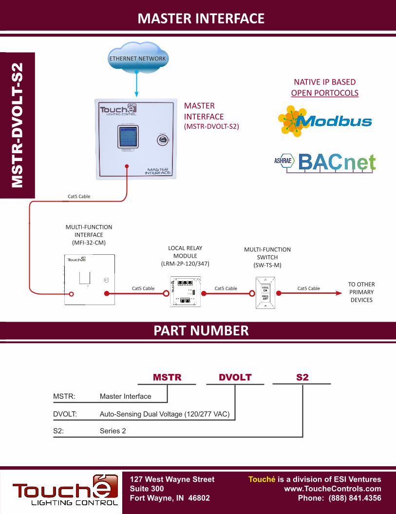
PART NUMBERSPECIFICATIONS
MSTR: Master Interface
MSTR
MS
TR
-DV
OLT
-S2
MASTERINTERFACE(MSTR-DVOLT-S2)
Cat5 Cable
MS
TR
-DV
OLT-S
2
DVOLT S2
DVOLT: Auto-Sensing Dual Voltage (120/277 VAC)
S2: Series 2
ETHERNET NETWORK
NATIVE IP BASED OPEN PORTOCOLS
127 West Wayne StreetSuite 300Fort Wayne, IN 46802
Touché is a division of ESI Ventureswww.ToucheControls.com
Phone: (888) 841.4356
MASTER INTERFACE
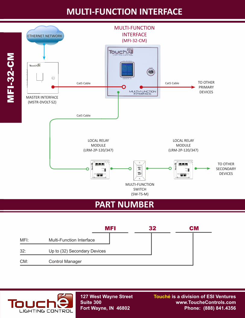
Cat5 Cable
MULTI-FUNCTIONINTERFACE
(MFI-32-CM) MULTI-FUNCTION
SWITCH(SW-TS-M)
LOCAL RELAYMODULE
(LRM-2P-120/347)
Cat5 CableTO OTHERPRIMARYDEVICES
Cat5 Cable
127 West Wayne StreetSuite 300Fort Wayne, IN 46802
SPECIFICATIONS
Touché is a division of ESI Ventureswww.ToucheControls.com
Phone: (888) 841.4356
MULTI-FUNCTION INTERFACE
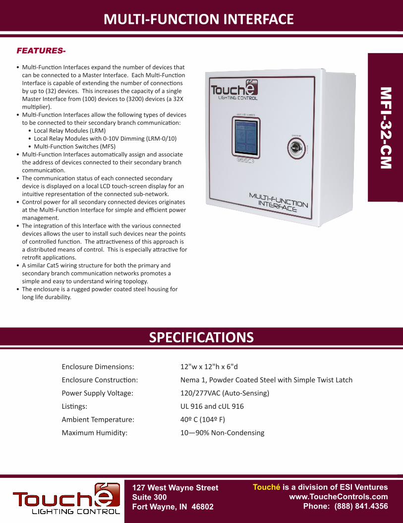
Enclosure Dimensions: 12"w x 12"h x 6"d
Enclosure Construction: Nema 1, Powder Coated Steel with Simple Twist Latch
Power Supply Voltage: 120/277VAC (Auto-Sensing)
Listings: UL 916 and cUL 916
Ambient Temperature: 40º C (104º F)
Maximum Humidity: 10—90% Non-Condensing
FEATURES-
• Multi-Function Interfaces expand the number of devices that can be connected to a Master Interface. Each Multi-Function Interface is capable of extending the number of connections by up to (32) devices. This increases the capacity of a single Master Interface from (100) devices to (3200) devices (a 32X multiplier).
• Multi-Function Interfaces allow the following types of devices to be connected to their secondary branch communication:
• Local Relay Modules (LRM)• Local Relay Modules with 0-10V Dimming (LRM-0/10)• Multi-Function Switches (MFS)
• Multi-Function Interfaces automatically assign and associate the address of devices connected to their secondary branch communication.
• The communication status of each connected secondary device is displayed on a local LCD touch-screen display for an intuitive representation of the connected sub-network.
• Control power for all secondary connected devices originates at the Multi-Function Interface for simple and efficient power management.
• The integration of this Interface with the various connected devices allows the user to install such devices near the points of controlled function. The attractiveness of this approach is a distributed means of control. This is especially attractive for retrofit applications.
• A similar Cat5 wiring structure for both the primary and secondary branch communication networks promotes a simple and easy to understand wiring topology.
• The enclosure is a rugged powder coated steel housing for long life durability.
MFI-32-C
M
MFI
-32-
CM
PART NUMBERSPECIFICATIONS
MFI-32-C
M
902 Incentive DriveFort Wayne, IN 46825
Touché is a division ofESI Ventures.
MASTER INTERFACE(MSTR-DVOLT-S2)
MULTI-FUNCTIONSWITCH
(SW-TS-M)
LOCAL RELAYMODULE
(LRM-2P-120/347)
MULTI-FUNCTIONINTERFACE(MFI-32-CM)
MULTI-FUNCTION INTERFACE
TO OTHERSECONDARY
DEVICES
TO OTHERPRIMARYDEVICES
LOCAL RELAYMODULE
(LRM-2P-120/347)
MFI
-32-
CM
MFI: Multi-Function Interface
MFI 32 CM
32: Up to (32) Secondary Devices
CM: Control Manager
ETHERNET NETWORK
127 West Wayne StreetSuite 300Fort Wayne, IN 46802
Touché is a division of ESI Ventureswww.ToucheControls.com
Phone: (888) 841.4356
Cat5 Cable Cat5 Cable
Cat5 Cable
127 West Wayne StreetSuite 300Fort Wayne, IN 46802
SPECIFICATIONS
Touché is a division of ESI Ventureswww.ToucheControls.com
Phone: (888) 841.4356
RELAY DIMMER PANEL
FEATURES-
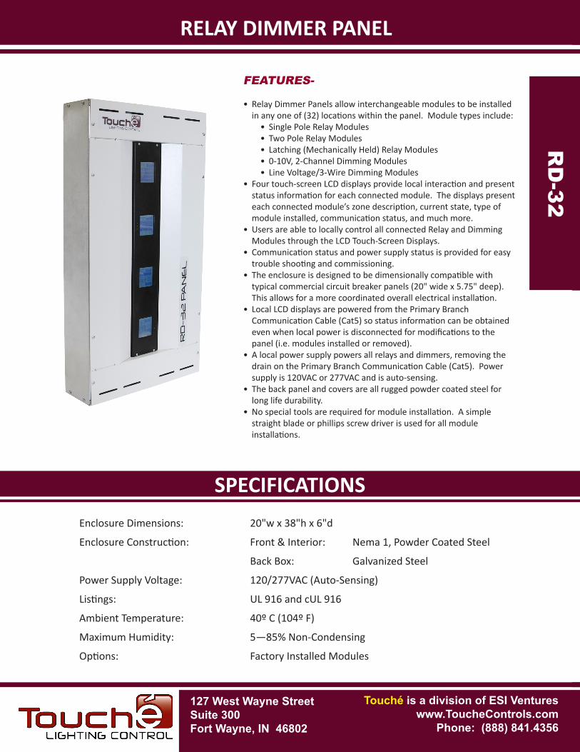
• Relay Dimmer Panels allow interchangeable modules to be installed in any one of (32) locations within the panel. Module types include:
• Single Pole Relay Modules• Two Pole Relay Modules• Latching (Mechanically Held) Relay Modules• 0-10V, 2-Channel Dimming Modules• Line Voltage/3-Wire Dimming Modules
• Four touch-screen LCD displays provide local interaction and present status information for each connected module. The displays present each connected module’s zone description, current state, type of module installed, communication status, and much more.
• Users are able to locally control all connected Relay and Dimming Modules through the LCD Touch-Screen Displays.
• Communication status and power supply status is provided for easy trouble shooting and commissioning.
• The enclosure is designed to be dimensionally compatible with typical commercial circuit breaker panels (20" wide x 5.75" deep). This allows for a more coordinated overall electrical installation.
• Local LCD displays are powered from the Primary Branch Communication Cable (Cat5) so status information can be obtained even when local power is disconnected for modifications to the panel (i.e. modules installed or removed).
• A local power supply powers all relays and dimmers, removing the drain on the Primary Branch Communication Cable (Cat5). Power supply is 120VAC or 277VAC and is auto-sensing.
• The back panel and covers are all rugged powder coated steel for long life durability.
• No special tools are required for module installation. A simple straight blade or phillips screw driver is used for all module installations.
Enclosure Dimensions: 20"w x 38"h x 6"d
Enclosure Construction: Front & Interior: Nema 1, Powder Coated Steel
Back Box: Galvanized Steel
Power Supply Voltage: 120/277VAC (Auto-Sensing)
Listings: UL 916 and cUL 916
Ambient Temperature: 40º C (104º F)
Maximum Humidity: 5—85% Non-Condensing
Options: Factory Installed Modules
RELAY DIMMER PANEL
RD
-32R
D-32
PART NUMBERSPECIFICATIONS
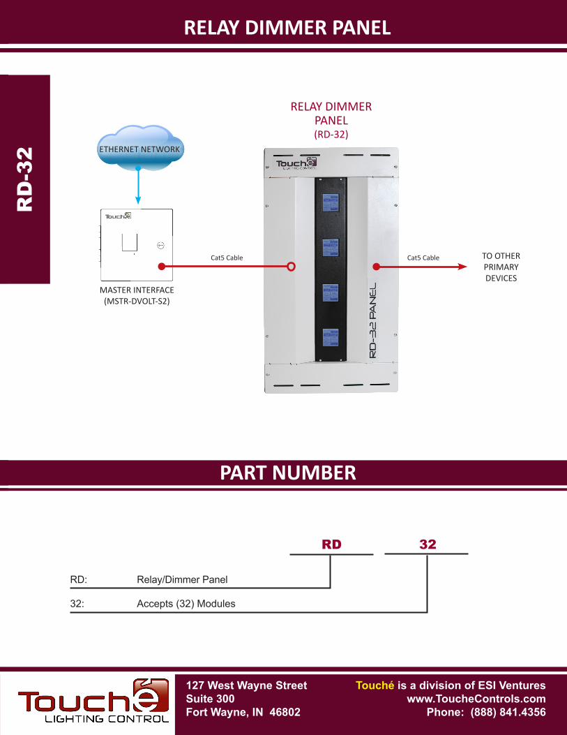
RELAY DIMMERPANEL(RD-32)
RELAY DIMMER PANEL
MASTER INTERFACE(MSTR-DVOLT-S2)
RD
-32R
D-32
RD 32
RD: Relay/Dimmer Panel
32: Accepts (32) Modules
ETHERNET NETWORK
127 West Wayne StreetSuite 300Fort Wayne, IN 46802
Touché is a division of ESI Ventureswww.ToucheControls.com
Phone: (888) 841.4356
Cat5 Cable TO OTHERPRIMARYDEVICES
Cat5 Cable
127 West Wayne StreetSuite 300Fort Wayne, IN 46802
SPECIFICATIONS
Touché is a division of ESI Ventureswww.ToucheControls.com
Phone: (888) 841.4356
RELAY DIMMER PANEL
FEATURES-
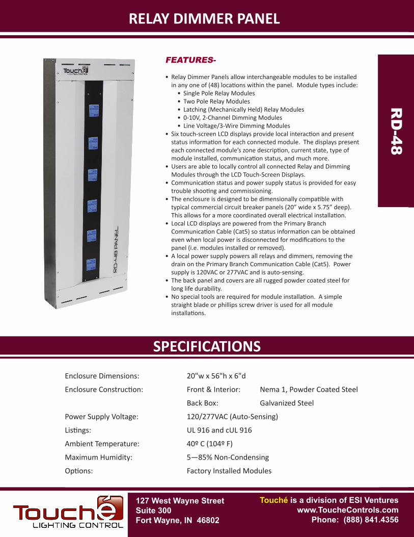
• Relay Dimmer Panels allow interchangeable modules to be installed in any one of (48) locations within the panel. Module types include:
• Single Pole Relay Modules• Two Pole Relay Modules• Latching (Mechanically Held) Relay Modules• 0-10V, 2-Channel Dimming Modules• Line Voltage/3-Wire Dimming Modules
• Six touch-screen LCD displays provide local interaction and present status information for each connected module. The displays present each connected module’s zone description, current state, type of module installed, communication status, and much more.
• Users are able to locally control all connected Relay and Dimming Modules through the LCD Touch-Screen Displays.
• Communication status and power supply status is provided for easy trouble shooting and commissioning.
• The enclosure is designed to be dimensionally compatible with typical commercial circuit breaker panels (20” wide x 5.75” deep). This allows for a more coordinated overall electrical installation.
• Local LCD displays are powered from the Primary Branch Communication Cable (Cat5) so status information can be obtained even when local power is disconnected for modifications to the panel (i.e. modules installed or removed).
• A local power supply powers all relays and dimmers, removing the drain on the Primary Branch Communication Cable (Cat5). Power supply is 120VAC or 277VAC and is auto-sensing.
• The back panel and covers are all rugged powder coated steel for long life durability.
• No special tools are required for module installation. A simple straight blade or phillips screw driver is used for all module installations.
Enclosure Dimensions: 20"w x 56"h x 6"d
Enclosure Construction: Front & Interior: Nema 1, Powder Coated Steel
Back Box: Galvanized Steel
Power Supply Voltage: 120/277VAC (Auto-Sensing)
Listings: UL 916 and cUL 916
Ambient Temperature: 40º C (104º F)
Maximum Humidity: 5—85% Non-Condensing
Options: Factory Installed Modules
RD
-48R
D-48
PART NUMBERSPECIFICATIONS
RELAY DIMMER PANEL
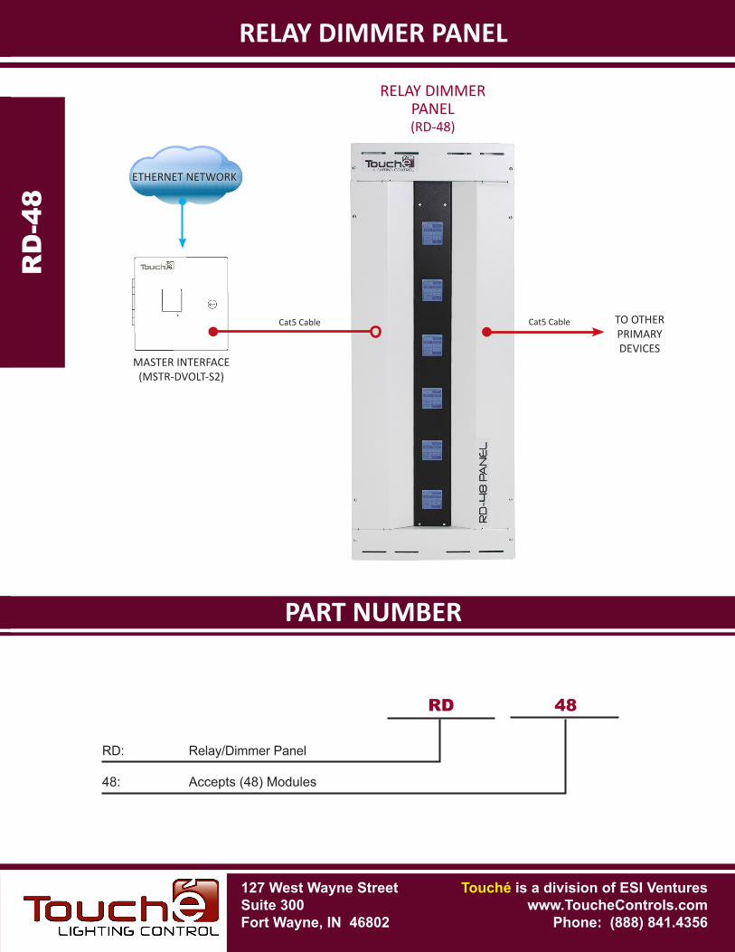
RELAY DIMMERPANEL(RD-48)
RD
-48R
D-48
RD 48
RD: Relay/Dimmer Panel
48: Accepts (48) Modules
127 West Wayne StreetSuite 300Fort Wayne, IN 46802
Touché is a division of ESI Ventureswww.ToucheControls.com
Phone: (888) 841.4356
MASTER INTERFACE(MSTR-DVOLT-S2)
Cat5 Cable TO OTHERPRIMARYDEVICES
Cat5 Cable
ETHERNET NETWORK
127 West Wayne StreetSuite 300Fort Wayne, IN 46802
SPECIFICATIONS
Touché is a division of ESI Ventureswww.ToucheControls.com
Phone: (888) 841.4356
SINGLE POLE RELAY MODULE
FEATURES-
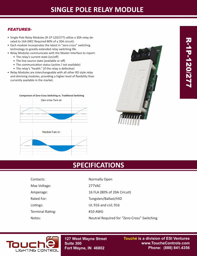
• Single Pole Relay Modules (R-1P-120/277) utilize a 30A relay de-rated to 16A (NEC Required 80% of a 20A circuit).
• Each module incorporates the latest in “zero-cross” switching technology to greatly extended relay switching life.
• Relay Modules communicate with the Master Interface to report:• The relay’s current state (on/off)• The line source state (available or off)• The communication status (active / not available)• The relay’s “health.” (if the relay is defective)
• Relay Modules are interchangeable with all other RD style relay and dimming modules, providing a higher level of flexibility than currently available in the market.
Contacts: Normally Open
Max Voltage: 277VAC
Amperage: 16 FLA (80% of 20A Circuit)
Rated For: Tungsten/Ballast/HID
Listings: UL 916 and cUL 916
Terminal Rating: #10 AWG
Notes: Neutral Required for “Zero-Cross” Switching
Comparison of Zero-Cross Switching vs. Traditional Switching
R-1
P-1
20/2
77
R-1P
-120/277
PART NUMBERSPECIFICATIONS
SINGLE POLE RELAY MODULE
RELAY-DIMMER PANEL(RD-32 OR RD-48)
R-1
P-1
20/2
77
R-1P
-120/277
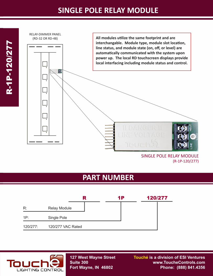
SINGLE POLE RELAY MODULE(R-1P-120/277)
R: Relay Module
R 1P 120/277
1P: Single Pole
120/277: 120/277 VAC Rated
All modules utilize the same footprint and are interchangable. Module type, module slot location, line status, and module state (on, off, or level) are automatically communicated with the system upon power up. The local RD touchscreen displays provide local interfacing including module status and control.
127 West Wayne StreetSuite 300Fort Wayne, IN 46802
Touché is a division of ESI Ventureswww.ToucheControls.com
Phone: (888) 841.4356
127 West Wayne StreetSuite 300Fort Wayne, IN 46802
SPECIFICATIONS
Touché is a division of ESI Ventureswww.ToucheControls.com
Phone: (888) 841.4356
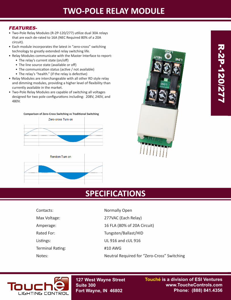
TWO-POLE RELAY MODULE
FEATURES-• Two-Pole Relay Modules (R-2P-120/277) utilize dual 30A relays
that are each de-rated to 16A (NEC Required 80% of a 20A circuit).
• Each module incorporates the latest in “zero-cross” switching technology to greatly extended relay switching life.
• Relay Modules communicate with the Master Interface to report:• The relay’s current state (on/off)• The line source state (available or off)• The communication status (active / not available)• The relay’s “health.” (if the relay is defective)
• Relay Modules are interchangeable with all other RD style relay and dimming modules, providing a higher level of flexibility than currently available in the market.
• Two-Pole Relay Modules are capable of switching all voltages designed for two pole configurations including: 208V, 240V, and 480V.
Contacts: Normally Open
Max Voltage: 277VAC (Each Relay)
Amperage: 16 FLA (80% of 20A Circuit)
Rated For: Tungsten/Ballast/HID
Listings: UL 916 and cUL 916
Terminal Rating: #10 AWG
Notes: Neutral Required for “Zero-Cross” Switching
R-2
P-1
20/2
77
R-2P
-120/277
Comparison of Zero-Cross Switching vs Traditional Switching
PART NUMBERSPECIFICATIONS
TWO-POLE RELAY MODULER
-2P
-120
/277
R-2P
-120/277
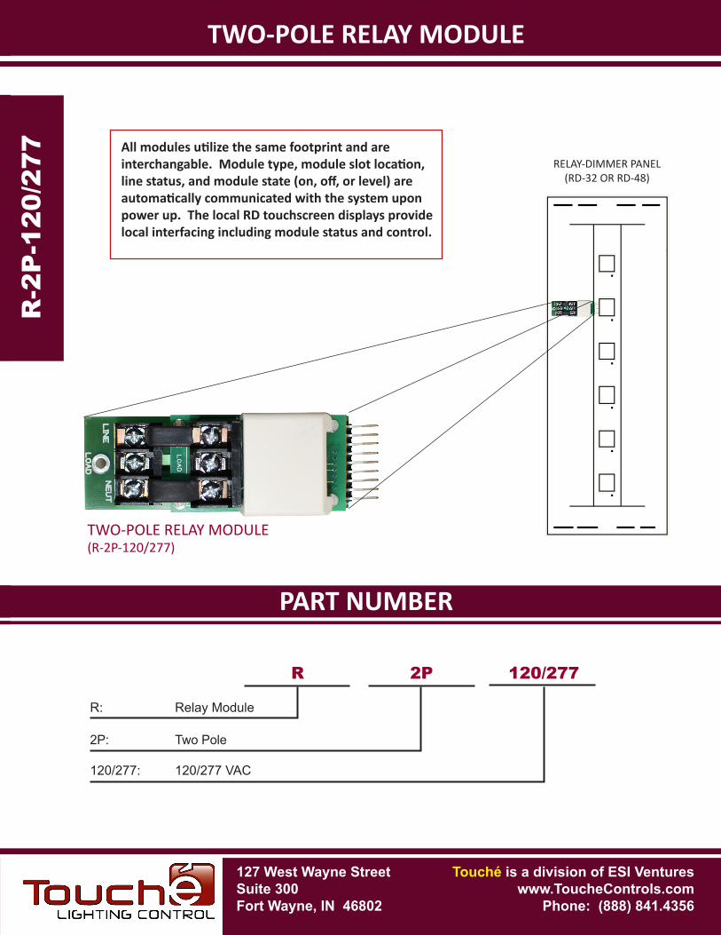
TWO-POLE RELAY MODULE(R-2P-120/277)
R: Relay Module
R 2P 120/277
2P: Two Pole
120/277: 120/277 VAC
All modules utilize the same footprint and are interchangable. Module type, module slot location, line status, and module state (on, off, or level) are automatically communicated with the system upon power up. The local RD touchscreen displays provide local interfacing including module status and control.
127 West Wayne StreetSuite 300Fort Wayne, IN 46802
Touché is a division of ESI Ventureswww.ToucheControls.com
Phone: (888) 841.4356
RELAY-DIMMER PANEL(RD-32 OR RD-48)
127 West Wayne StreetSuite 300Fort Wayne, IN 46802
SPECIFICATIONS
Touché is a division of ESI Ventureswww.ToucheControls.com
Phone: (888) 841.4356
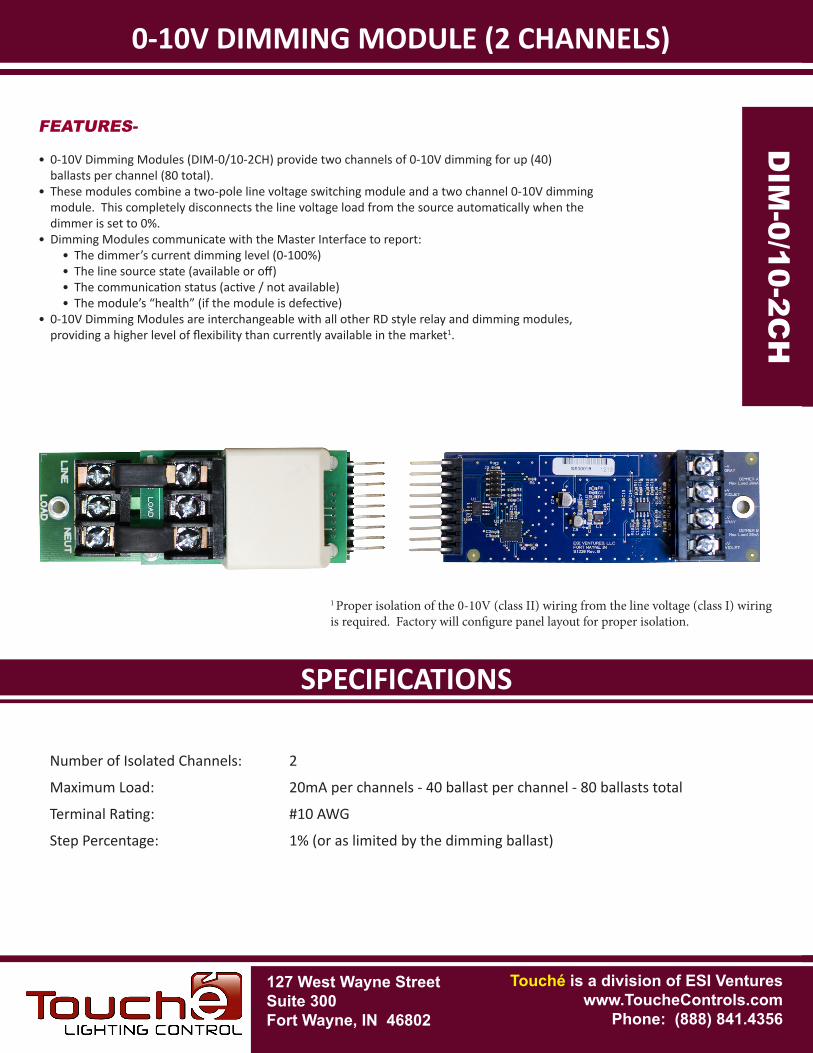
0-10V DIMMING MODULE (2 CHANNELS)
FEATURES-
• 0-10V Dimming Modules (DIM-0/10-2CH) provide two channels of 0-10V dimming for up (40) ballasts per channel (80 total).
• These modules combine a two-pole line voltage switching module and a two channel 0-10V dimming module. This completely disconnects the line voltage load from the source automatically when the dimmer is set to 0%.
• Dimming Modules communicate with the Master Interface to report:• The dimmer’s current dimming level (0-100%)• The line source state (available or off)• The communication status (active / not available)• The module’s “health” (if the module is defective)
• 0-10V Dimming Modules are interchangeable with all other RD style relay and dimming modules, providing a higher level of flexibility than currently available in the market1.
Number of Isolated Channels: 2
Maximum Load: 20mA per channels - 40 ballast per channel - 80 ballasts total
Terminal Rating: #10 AWG
Step Percentage: 1% (or as limited by the dimming ballast)D
IM-0
/10-
2CH
DIM
-0/10-2CH
1 Proper isolation of the 0-10V (class II) wiring from the line voltage (class I) wiring is required. Factory will configure panel layout for proper isolation.
PART NUMBERSPECIFICATIONS
0-10V DIMMING MODULE (2 CHANNELS)D
IM-0
/10-
2CH
DIM
-0/10-2CH
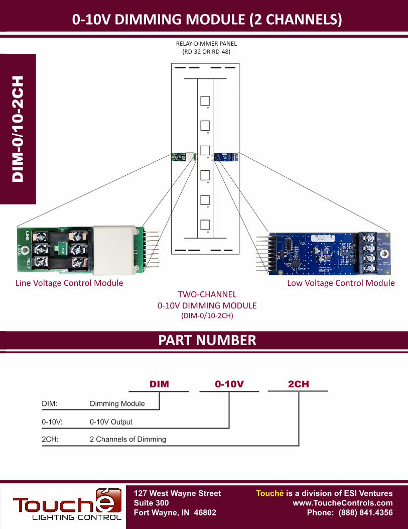
Low Voltage Control Module
RELAY-DIMMER PANEL(RD-32 OR RD-48)
DIM: Dimming Module
DIM 0-10V 2CH
0-10V: 0-10V Output
2CH: 2 Channels of Dimming
Line Voltage Control ModuleTWO-CHANNEL
0-10V DIMMING MODULE(DIM-0/10-2CH)
127 West Wayne StreetSuite 300Fort Wayne, IN 46802
Touché is a division of ESI Ventureswww.ToucheControls.com
Phone: (888) 841.4356
127 West Wayne StreetSuite 300Fort Wayne, IN 46802
SPECIFICATIONS
Touché is a division of ESI Ventureswww.ToucheControls.com
Phone: (888) 841.4356
LINE VOLTAGE & 3-WIRE DIMMING MODULE
FEATURES-
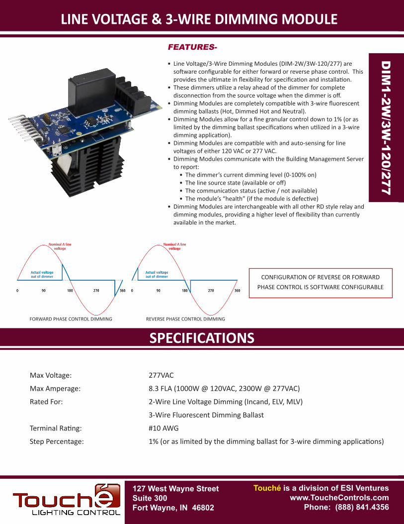
• Line Voltage/3-Wire Dimming Modules (DIM-2W/3W-120/277) are software configurable for either forward or reverse phase control. This provides the ultimate in flexibility for specification and installation.
• These dimmers utilize a relay ahead of the dimmer for complete disconnection from the source voltage when the dimmer is off.
• Dimming Modules are completely compatible with 3-wire fluorescent dimming ballasts (Hot, Dimmed Hot and Neutral).
• Dimming Modules allow for a fine granular control down to 1% (or as limited by the dimming ballast specifications when utilized in a 3-wire dimming application).
• Dimming Modules are compatible with and auto-sensing for line voltages of either 120 VAC or 277 VAC.
• Dimming Modules communicate with the Building Management Server to report:
• The dimmer’s current dimming level (0-100% on)• The line source state (available or off)• The communication status (active / not available)• The module’s “health” (if the module is defective)
• Dimming Modules are interchangeable with all other RD style relay and dimming modules, providing a higher level of flexibility than currently available in the market.
Max Voltage: 277VAC
Max Amperage: 8.3 FLA (1000W @ 120VAC, 2300W @ 277VAC)
Rated For: 2-Wire Line Voltage Dimming (Incand, ELV, MLV)
3-Wire Fluorescent Dimming Ballast
Terminal Rating: #10 AWG
Step Percentage: 1% (or as limited by the dimming ballast for 3-wire dimming applications)
FORWARD PHASE CONTROL DIMMING
DIM
1-2W
/3W
-120
/277
DIM
1-2W/3W
-120/277
REVERSE PHASE CONTROL DIMMING
CONFIGURATION OF REVERSE OR FORWARD PHASE CONTROL IS SOFTWARE CONFIGURABLE
PART NUMBERSPECIFICATIONS
LINE VOLTAGE & 3-WIRE DIMMING MODULE
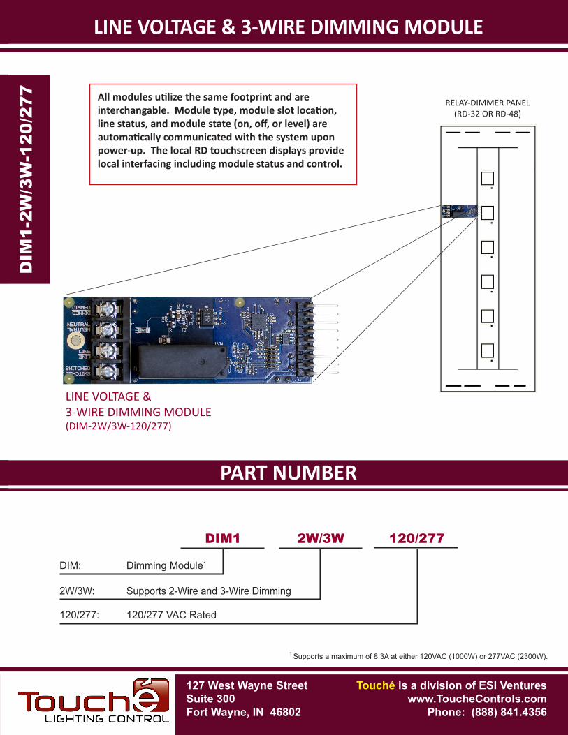
LINE VOLTAGE &3-WIRE DIMMING MODULE(DIM-2W/3W-120/277)
DIM
1-2W
/3W
-120
/277
DIM
1-2W/3W
-120/277
DIM: Dimming Module1
DIM1 2W/3W 120/277
2W/3W: Supports 2-Wire and 3-Wire Dimming
120/277: 120/277 VAC Rated
1 Supports a maximum of 8.3A at either 120VAC (1000W) or 277VAC (2300W).
All modules utilize the same footprint and are interchangable. Module type, module slot location, line status, and module state (on, off, or level) are automatically communicated with the system upon power-up. The local RD touchscreen displays provide local interfacing including module status and control.
127 West Wayne StreetSuite 300Fort Wayne, IN 46802
Touché is a division of ESI Ventureswww.ToucheControls.com
Phone: (888) 841.4356
RELAY-DIMMER PANEL(RD-32 OR RD-48)
127 West Wayne StreetSuite 300Fort Wayne, IN 46802
SPECIFICATIONS
Touché is a division of ESI Ventureswww.ToucheControls.com
Phone: (888) 841.4356
LATCHING SINGLE POLE RELAY MODULE
FEATURES-
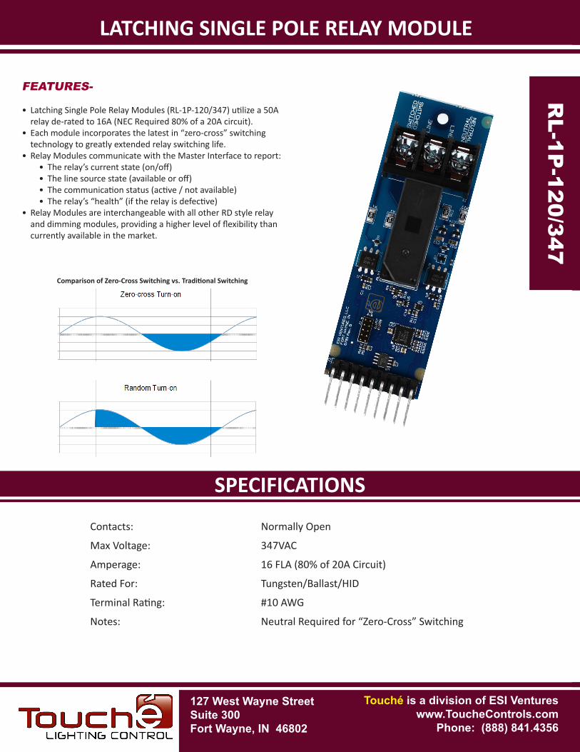
• Latching Single Pole Relay Modules (RL-1P-120/347) utilize a 50A relay de-rated to 16A (NEC Required 80% of a 20A circuit).
• Each module incorporates the latest in “zero-cross” switching technology to greatly extended relay switching life.
• Relay Modules communicate with the Master Interface to report:• The relay’s current state (on/off)• The line source state (available or off)• The communication status (active / not available)• The relay’s “health” (if the relay is defective)
• Relay Modules are interchangeable with all other RD style relay and dimming modules, providing a higher level of flexibility than currently available in the market.
Contacts: Normally Open
Max Voltage: 347VAC
Amperage: 16 FLA (80% of 20A Circuit)
Rated For: Tungsten/Ballast/HID
Terminal Rating: #10 AWG
Notes: Neutral Required for “Zero-Cross” Switching
Comparison of Zero-Cross Switching vs. Traditional Switching
RL-1P
-120/347 RL-
1P-1
20/3
47
PART NUMBERSPECIFICATIONS
RL-1P
-120/347
LATCHING SINGLE POLE RELAY MODULE
RELAY-DIMMER PANEL(RD-32 OR RD-48)
RL-
1P-1
20/3
47
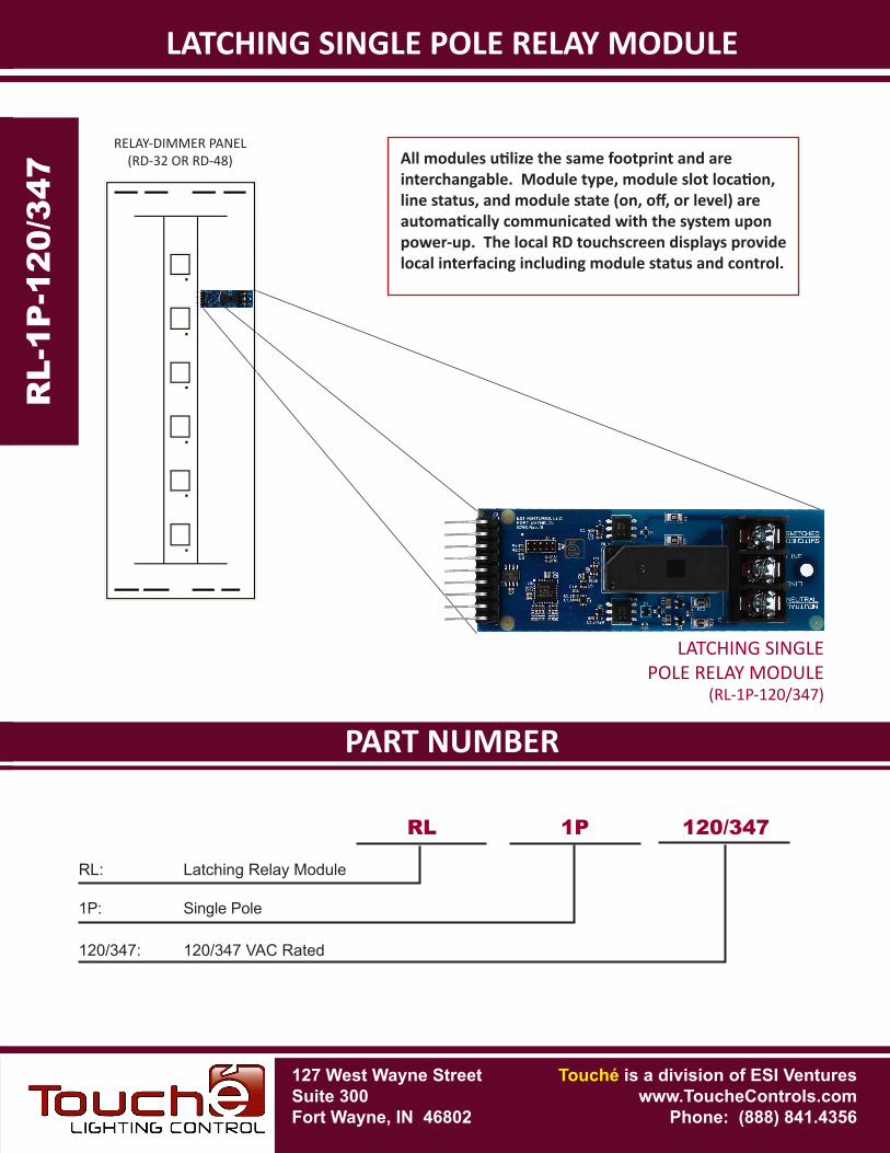
LATCHING SINGLEPOLE RELAY MODULE
(RL-1P-120/347)
RL: Latching Relay Module
RL 1P 120/347
1P: Single Pole
120/347: 120/347 VAC Rated
All modules utilize the same footprint and are interchangable. Module type, module slot location, line status, and module state (on, off, or level) are automatically communicated with the system upon power-up. The local RD touchscreen displays provide local interfacing including module status and control.
127 West Wayne StreetSuite 300Fort Wayne, IN 46802
Touché is a division of ESI Ventureswww.ToucheControls.com
Phone: (888) 841.4356
127 West Wayne StreetSuite 300Fort Wayne, IN 46802
SPECIFICATIONS
Touché is a division of ESI Ventureswww.ToucheControls.com
Phone: (888) 841.4356
TWO-POLE STEP RELAY MODULE
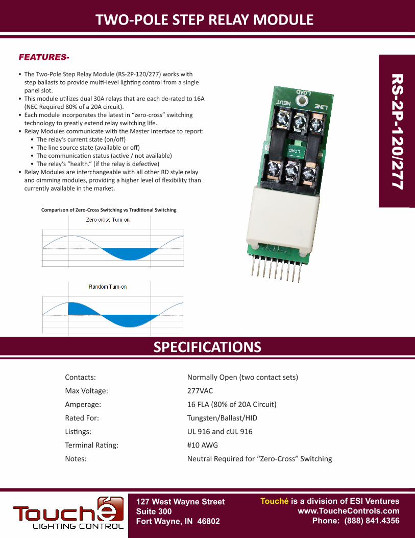
Contacts: Normally Open (two contact sets)
Max Voltage: 277VAC
Amperage: 16 FLA (80% of 20A Circuit)
Rated For: Tungsten/Ballast/HID
Listings: UL 916 and cUL 916
Terminal Rating: #10 AWG
Notes: Neutral Required for “Zero-Cross” Switching
RS
-2P
-120
/277
RS
-2P-120/277
Comparison of Zero-Cross Switching vs Traditional Switching
FEATURES-
• The Two-Pole Step Relay Module (RS-2P-120/277) works with step ballasts to provide multi-level lighting control from a single panel slot.
• This module utilizes dual 30A relays that are each de-rated to 16A (NEC Required 80% of a 20A circuit).
• Each module incorporates the latest in “zero-cross” switching technology to greatly extend relay switching life.
• Relay Modules communicate with the Master Interface to report:• The relay’s current state (on/off)• The line source state (available or off)• The communication status (active / not available)• The relay’s “health.” (if the relay is defective)
• Relay Modules are interchangeable with all other RD style relay and dimming modules, providing a higher level of flexibility than currently available in the market.

PART NUMBERSPECIFICATIONS
TWO-POLE STEP RELAY MODULER
S-2
P-1
20/2
77
RS
-2P-120/277
TWO-POLE STEP RELAY MODULE(RS-2P-120/277)
RS: Step Relay Module
RS 2P 120/277
2P: Two Pole
120/277: 120/277 VAC
All modules utilize the same footprint and are interchangable. Module type, module slot location, line status, and module state (on, off, or level) are automatically communicated with the system upon power-up. The local RD touchscreen displays provide local interfacing including module status and control.
127 West Wayne StreetSuite 300Fort Wayne, IN 46802
Touché is a division of ESI Ventureswww.ToucheControls.com
Phone: (888) 841.4356
RELAY-DIMMER PANEL(RD-32 OR RD-48)
127 West Wayne StreetSuite 300Fort Wayne, IN 46802
SPECIFICATIONS
Touché is a division of ESI Ventureswww.ToucheControls.com
Phone: (888) 841.4356
LOCAL RELAY MODULEFEATURES-
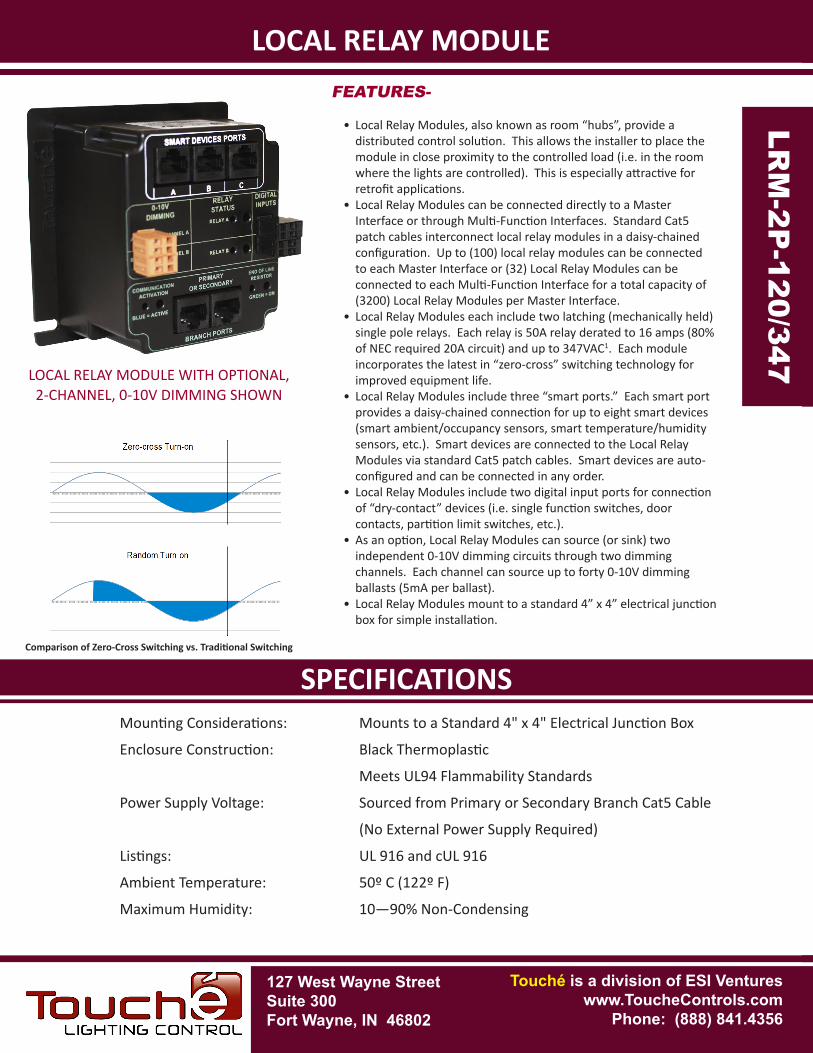
• Local Relay Modules, also known as room “hubs”, provide a distributed control solution. This allows the installer to place the module in close proximity to the controlled load (i.e. in the room where the lights are controlled). This is especially attractive for retrofit applications.
• Local Relay Modules can be connected directly to a Master Interface or through Multi-Function Interfaces. Standard Cat5 patch cables interconnect local relay modules in a daisy-chained configuration. Up to (100) local relay modules can be connected to each Master Interface or (32) Local Relay Modules can be connected to each Multi-Function Interface for a total capacity of (3200) Local Relay Modules per Master Interface.
• Local Relay Modules each include two latching (mechanically held) single pole relays. Each relay is 50A relay derated to 16 amps (80% of NEC required 20A circuit) and up to 347VAC1. Each module incorporates the latest in “zero-cross” switching technology for improved equipment life.
• Local Relay Modules include three “smart ports.” Each smart port provides a daisy-chained connection for up to eight smart devices (smart ambient/occupancy sensors, smart temperature/humidity sensors, etc.). Smart devices are connected to the Local Relay Modules via standard Cat5 patch cables. Smart devices are auto-configured and can be connected in any order.
• Local Relay Modules include two digital input ports for connection of “dry-contact” devices (i.e. single function switches, door contacts, partition limit switches, etc.).
• As an option, Local Relay Modules can source (or sink) two independent 0-10V dimming circuits through two dimming channels. Each channel can source up to forty 0-10V dimming ballasts (5mA per ballast).
• Local Relay Modules mount to a standard 4” x 4” electrical junction box for simple installation.
Mounting Considerations: Mounts to a Standard 4" x 4" Electrical Junction Box
Enclosure Construction: Black Thermoplastic
Meets UL94 Flammability Standards
Power Supply Voltage: Sourced from Primary or Secondary Branch Cat5 Cable
(No External Power Supply Required)
Listings: UL 916 and cUL 916
Ambient Temperature: 50º C (122º F)
Maximum Humidity: 10—90% Non-Condensing
LRM
-2P
-120
/347
LRM
-2P-120/347
Comparison of Zero-Cross Switching vs. Traditional Switching
LOCAL RELAY MODULE WITH OPTIONAL, 2-CHANNEL, 0-10V DIMMING SHOWN
PART NUMBERSPECIFICATIONS
LOCAL RELAY MODULELR
M-2
P-1
20/3
47
LRM
-2P-120/347
LRM: Local Relay Module
LRM 2P 120/347
2P: Two Pole Module
120/347: 120/3471 VAC Rated
0/10: 2-Channels of 0-10V Dimming
1 Currently this module is UL/cUL listed to 277VAC (347VAC Under Review).
127 West Wayne StreetSuite 300Fort Wayne, IN 46802
Touché is a division of ESI Ventureswww.ToucheControls.com
Phone: (888) 841.4356
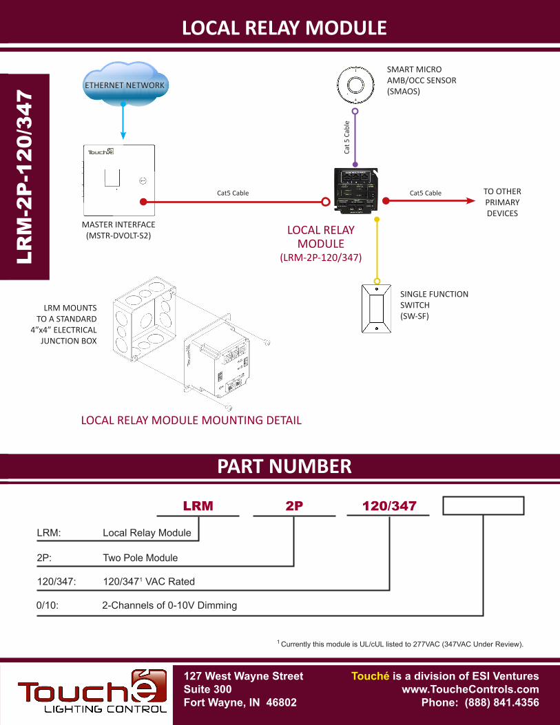
SINGLE FUNCTION SWITCH(SW-SF)
SMART MICROAMB/OCC SENSOR(SMAOS)
MASTER INTERFACE(MSTR-DVOLT-S2)
Cat5 Cable
LOCAL RELAY MODULE
(LRM-2P-120/347)
Cat 5
Cab
le
ETHERNET NETWORK
LOCAL RELAY MODULE MOUNTING DETAIL
TO OTHERPRIMARYDEVICES
Cat5 Cable
LRM MOUNTS TO A STANDARD
4”x4” ELECTRICAL JUNCTION BOX
127 West Wayne StreetSuite 300Fort Wayne, IN 46802
SPECIFICATIONS
Touché is a division of ESI Ventureswww.ToucheControls.com
Phone: (888) 841.4356
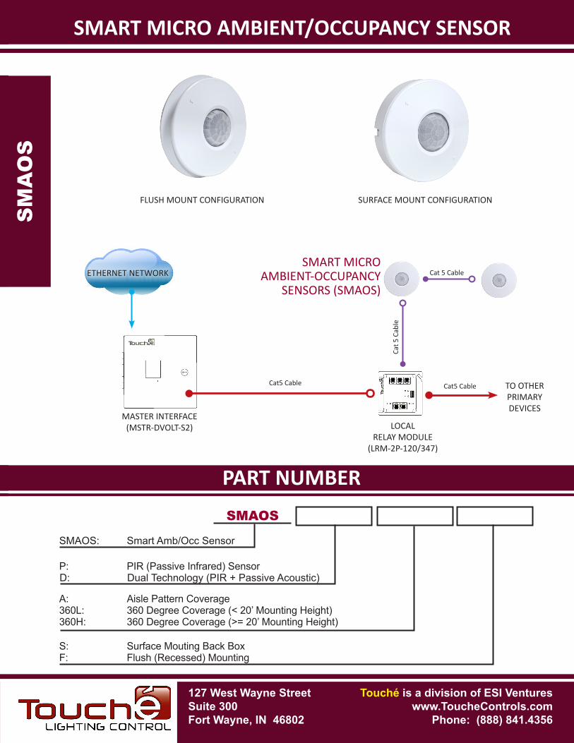
SMART MICRO AMBIENT/OCCUPANCY SENSOR
FEATURES-
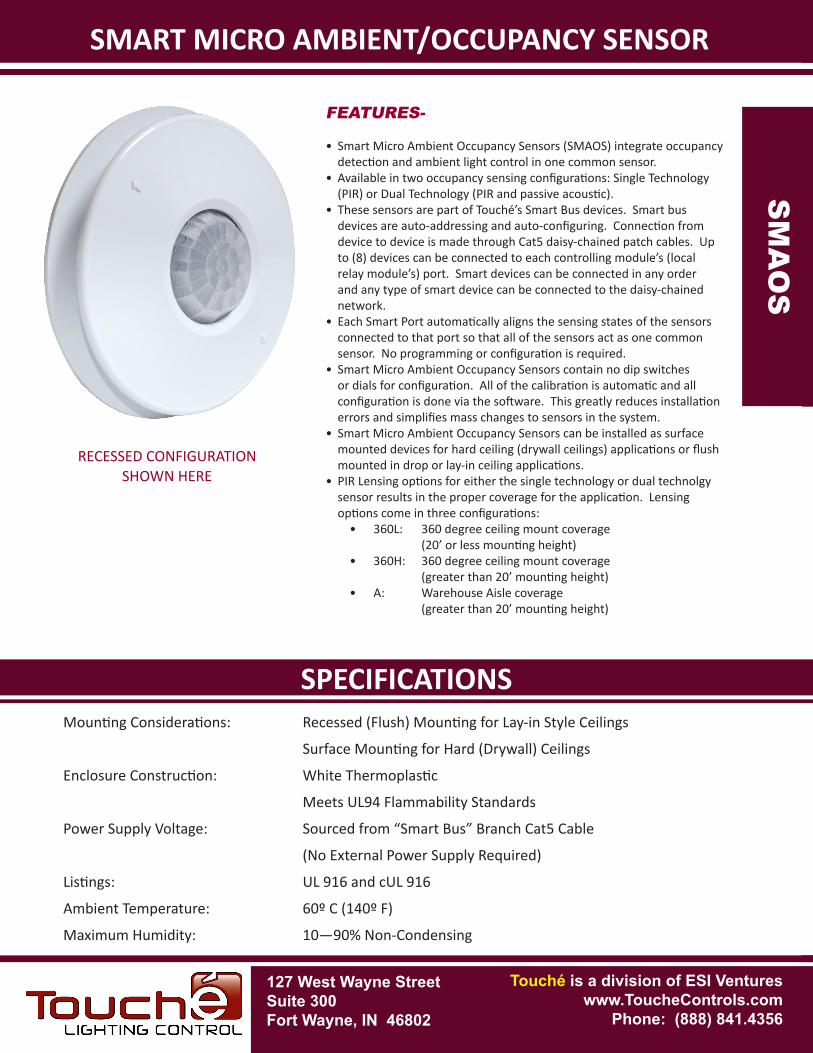
• Smart Micro Ambient Occupancy Sensors (SMAOS) integrate occupancy detection and ambient light control in one common sensor.
• Available in two occupancy sensing configurations: Single Technology (PIR) or Dual Technology (PIR and passive acoustic).
• These sensors are part of Touché’s Smart Bus devices. Smart bus devices are auto-addressing and auto-configuring. Connection from device to device is made through Cat5 daisy-chained patch cables. Up to (8) devices can be connected to each controlling module’s (local relay module’s) port. Smart devices can be connected in any order and any type of smart device can be connected to the daisy-chained network.
• Each Smart Port automatically aligns the sensing states of the sensors connected to that port so that all of the sensors act as one common sensor. No programming or configuration is required.
• Smart Micro Ambient Occupancy Sensors contain no dip switches or dials for configuration. All of the calibration is automatic and all configuration is done via the software. This greatly reduces installation errors and simplifies mass changes to sensors in the system.
• Smart Micro Ambient Occupancy Sensors can be installed as surface mounted devices for hard ceiling (drywall ceilings) applications or flush mounted in drop or lay-in ceiling applications.
• PIR Lensing options for either the single technology or dual technolgy sensor results in the proper coverage for the application. Lensing options come in three configurations:
• 360L: 360 degree ceiling mount coverage (20’ or less mounting height)
• 360H: 360 degree ceiling mount coverage (greater than 20’ mounting height)
• A: Warehouse Aisle coverage (greater than 20’ mounting height)
Mounting Considerations: Recessed (Flush) Mounting for Lay-in Style Ceilings
Surface Mounting for Hard (Drywall) Ceilings
Enclosure Construction: White Thermoplastic
Meets UL94 Flammability Standards
Power Supply Voltage: Sourced from “Smart Bus” Branch Cat5 Cable
(No External Power Supply Required)
Listings: UL 916 and cUL 916
Ambient Temperature: 60º C (140º F)
Maximum Humidity: 10—90% Non-Condensing
SM
AO
S
SM
AO
S
RECESSED CONFIGURATION SHOWN HERE
PART NUMBERSPECIFICATIONS
SMART MICRO AMBIENT/OCCUPANCY SENSORS
MA
OS
SM
AO
S
SMAOS: Smart Amb/Occ Sensor
SMAOS
P: PIR (Passive Infrared) Sensor
360L: 360 Degree Coverage (< 20’ Mounting Height)A: Aisle Pattern Coverage
F: Flush (Recessed) MountingS: Surface Mouting Back Box
360H: 360 Degree Coverage (>= 20’ Mounting Height)
D: Dual Technology (PIR + Passive Acoustic)
FLUSH MOUNT CONFIGURATION SURFACE MOUNT CONFIGURATION
127 West Wayne StreetSuite 300Fort Wayne, IN 46802
Touché is a division of ESI Ventureswww.ToucheControls.com
Phone: (888) 841.4356
MASTER INTERFACE(MSTR-DVOLT-S2)
Cat5 Cable
Cat 5
Cab
leCat5 Cable TO OTHER
PRIMARYDEVICES
LOCALRELAY MODULE
(LRM-2P-120/347)
SMART MICROAMBIENT-OCCUPANCY
SENSORS (SMAOS)Cat 5 CableETHERNET NETWORK
127 West Wayne StreetSuite 300Fort Wayne, IN 46802
SPECIFICATIONS
Touché is a division of ESI Ventureswww.ToucheControls.com
Phone: (888) 841.4356
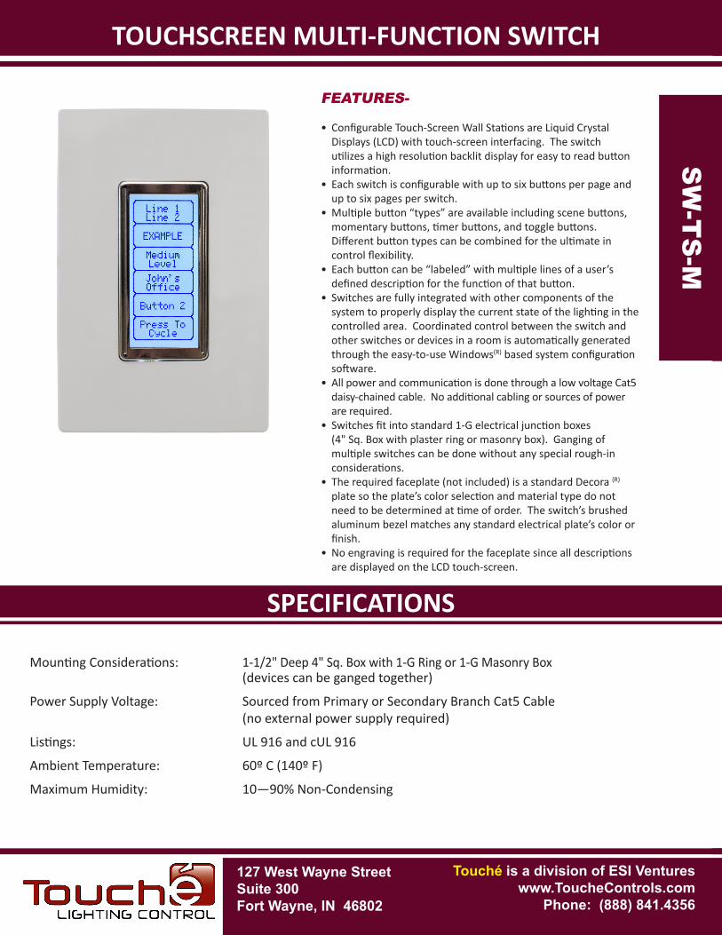
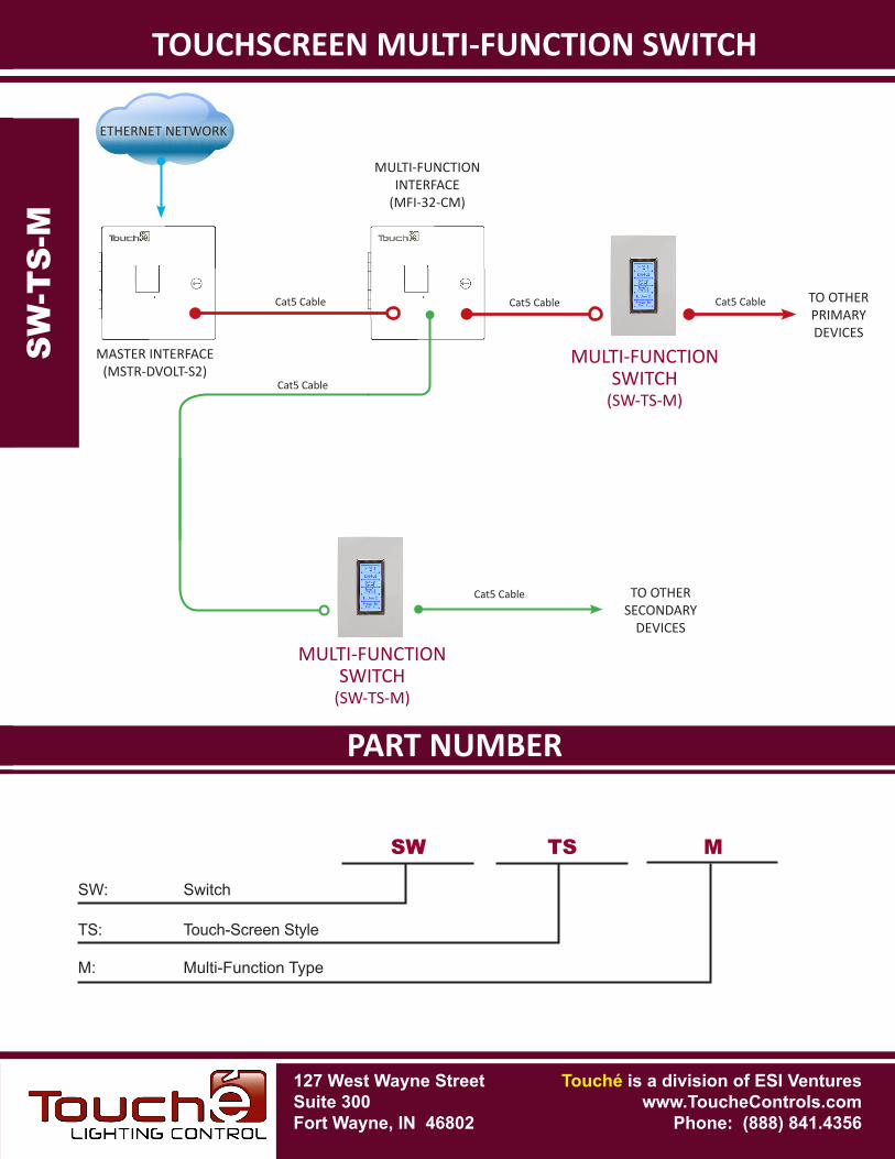
TOUCHSCREEN MULTI-FUNCTION SWITCH
FEATURES-
• Configurable Touch-Screen Wall Stations are Liquid Crystal Displays (LCD) with touch-screen interfacing. The switch utilizes a high resolution backlit display for easy to read button information.
• Each switch is configurable with up to six buttons per page and up to six pages per switch.
• Multiple button “types” are available including scene buttons, momentary buttons, timer buttons, and toggle buttons. Different button types can be combined for the ultimate in control flexibility.
• Each button can be “labeled” with multiple lines of a user’s defined description for the function of that button.
• Switches are fully integrated with other components of the system to properly display the current state of the lighting in the controlled area. Coordinated control between the switch and other switches or devices in a room is automatically generated through the easy-to-use Windows(R) based system configuration software.
• All power and communication is done through a low voltage Cat5 daisy-chained cable. No additional cabling or sources of power are required.
• Switches fit into standard 1-G electrical junction boxes (4" Sq. Box with plaster ring or masonry box). Ganging of multiple switches can be done without any special rough-in considerations.
• The required faceplate (not included) is a standard Decora (R) plate so the plate’s color selection and material type do not need to be determined at time of order. The switch’s brushed aluminum bezel matches any standard electrical plate’s color or finish.
• No engraving is required for the faceplate since all descriptions are displayed on the LCD touch-screen.
Mounting Considerations: 1-1/2" Deep 4" Sq. Box with 1-G Ring or 1-G Masonry Box (devices can be ganged together)
Power Supply Voltage: Sourced from Primary or Secondary Branch Cat5 Cable (no external power supply required)
Listings: UL 916 and cUL 916
Ambient Temperature: 60º C (140º F)
Maximum Humidity: 10—90% Non-Condensing
SW
-TS
-M
SW
-TS
-M
PART NUMBERSPECIFICATIONS
TOUCHSCREEN MULTI-FUNCTION SWITCH
Touché is a division ofESI Ventures.
TOUCHSCREEN MULTI-FUNCTION SWITCH
MULTI-FUNCTIONSWITCH
(SW-TS-M)
SW
-TS
-M
SW
-TS
-M
MASTER INTERFACE(MSTR-DVOLT-S2)
Cat5 Cable Cat5 Cable Cat5 Cable
TO OTHERSECONDARY
DEVICES
Cat5 Cable
TO OTHERPRIMARYDEVICES
Cat5 Cable
MULTI-FUNCTIONINTERFACE
(MFI-32-CM)
MULTI-FUNCTIONSWITCH
(SW-TS-M)
SW: Switch
SW TS M
TS: Touch-Screen Style
M: Multi-Function Type
ETHERNET NETWORK
127 West Wayne StreetSuite 300Fort Wayne, IN 46802
Touché is a division of ESI Ventureswww.ToucheControls.com
Phone: (888) 841.4356
127 West Wayne StreetSuite 300Fort Wayne, IN 46802
SPECIFICATIONS
Touché is a division of ESI Ventureswww.ToucheControls.com
Phone: (888) 841.4356
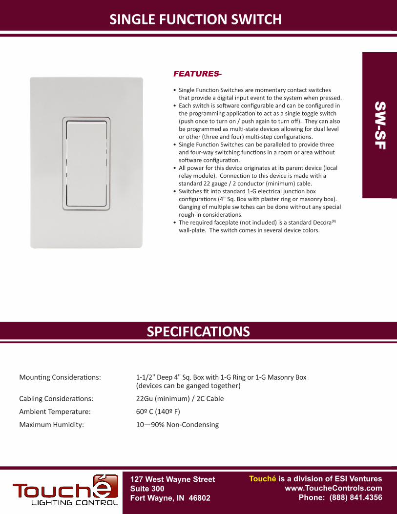
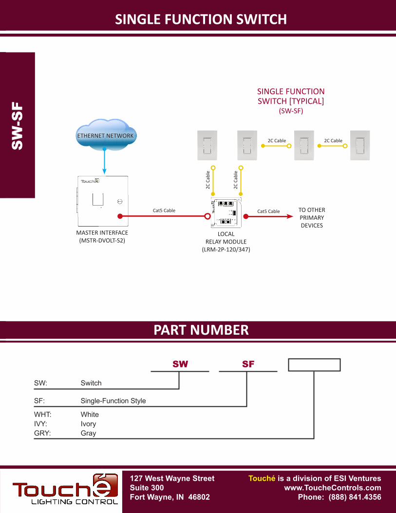
SINGLE FUNCTION SWITCH
FEATURES-
• Single Function Switches are momentary contact switches that provide a digital input event to the system when pressed.
• Each switch is software configurable and can be configured in the programming application to act as a single toggle switch (push once to turn on / push again to turn off). They can also be programmed as multi-state devices allowing for dual level or other (three and four) multi-step configurations.
• Single Function Switches can be paralleled to provide three and four-way switching functions in a room or area without software configuration.
• All power for this device originates at its parent device (local relay module). Connection to this device is made with a standard 22 gauge / 2 conductor (minimum) cable.
• Switches fit into standard 1-G electrical junction box configurations (4" Sq. Box with plaster ring or masonry box). Ganging of multiple switches can be done without any special rough-in considerations.
• The required faceplate (not included) is a standard Decora(R) wall-plate. The switch comes in several device colors.
Mounting Considerations: 1-1/2" Deep 4" Sq. Box with 1-G Ring or 1-G Masonry Box (devices can be ganged together)
Cabling Considerations: 22Gu (minimum) / 2C Cable
Ambient Temperature: 60º C (140º F)
Maximum Humidity: 10—90% Non-CondensingS
W-S
F
SW
-SF
PART NUMBERSPECIFICATIONS
SINGLE FUNCTION SWITCHS
W-S
F
SW
-SF
SW: Switch
SW SF
SF: Single-Function Style
WHT: WhiteIVY: IvoryGRY: Gray
127 West Wayne StreetSuite 300Fort Wayne, IN 46802
Touché is a division of ESI Ventureswww.ToucheControls.com
Phone: (888) 841.4356
2C C
able
SINGLE FUNCTIONSWITCH [TYPICAL]
(SW-SF)
MASTER INTERFACE(MSTR-DVOLT-S2)
Cat5 Cable TO OTHERPRIMARYDEVICES
2C C
able
2C Cable 2C CableETHERNET NETWORK
LOCALRELAY MODULE
(LRM-2P-120/347)
Cat5 Cable
127 West Wayne StreetSuite 300Fort Wayne, IN 46802
SPECIFICATIONS
Touché is a division of ESI Ventureswww.ToucheControls.com
Phone: (888) 841.4356
OCCUPANCY SENSOR SWITCH
Mounting Considerations: 1-1/2" Deep 4" Sq. Box with 1-G Ring or 1-G Masonry Box (devices can be ganged together)
Power Supply Voltage: 120/277VAC (Auto-Sensing)
Listings: UL773A
Ambient Temperature: 40º C (104º F)
Maximum Humidity: 10—90% Non-Condensing
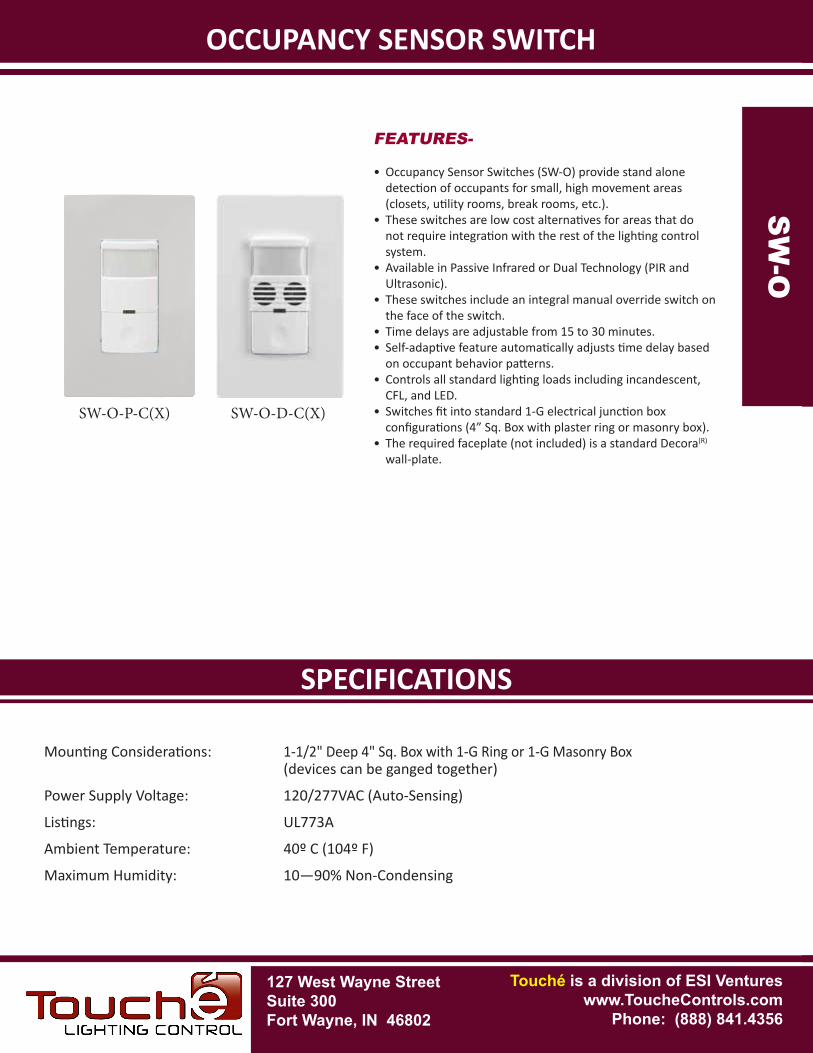
FEATURES-
• Occupancy Sensor Switches (SW-O) provide stand alone detection of occupants for small, high movement areas (closets, utility rooms, break rooms, etc.).
• These switches are low cost alternatives for areas that do not require integration with the rest of the lighting control system.
• Available in Passive Infrared or Dual Technology (PIR and Ultrasonic).
• These switches include an integral manual override switch on the face of the switch.
• Time delays are adjustable from 15 to 30 minutes.• Self-adaptive feature automatically adjusts time delay based
on occupant behavior patterns.• Controls all standard lighting loads including incandescent,
CFL, and LED.• Switches fit into standard 1-G electrical junction box
configurations (4” Sq. Box with plaster ring or masonry box). • The required faceplate (not included) is a standard Decora(R)
wall-plate.
SW-O-P-C(X) SW-O-D-C(X)
SW
-O
SW
-O
PART NUMBERSPECIFICATIONS
OCCUPANCY SENSOR SWITCH
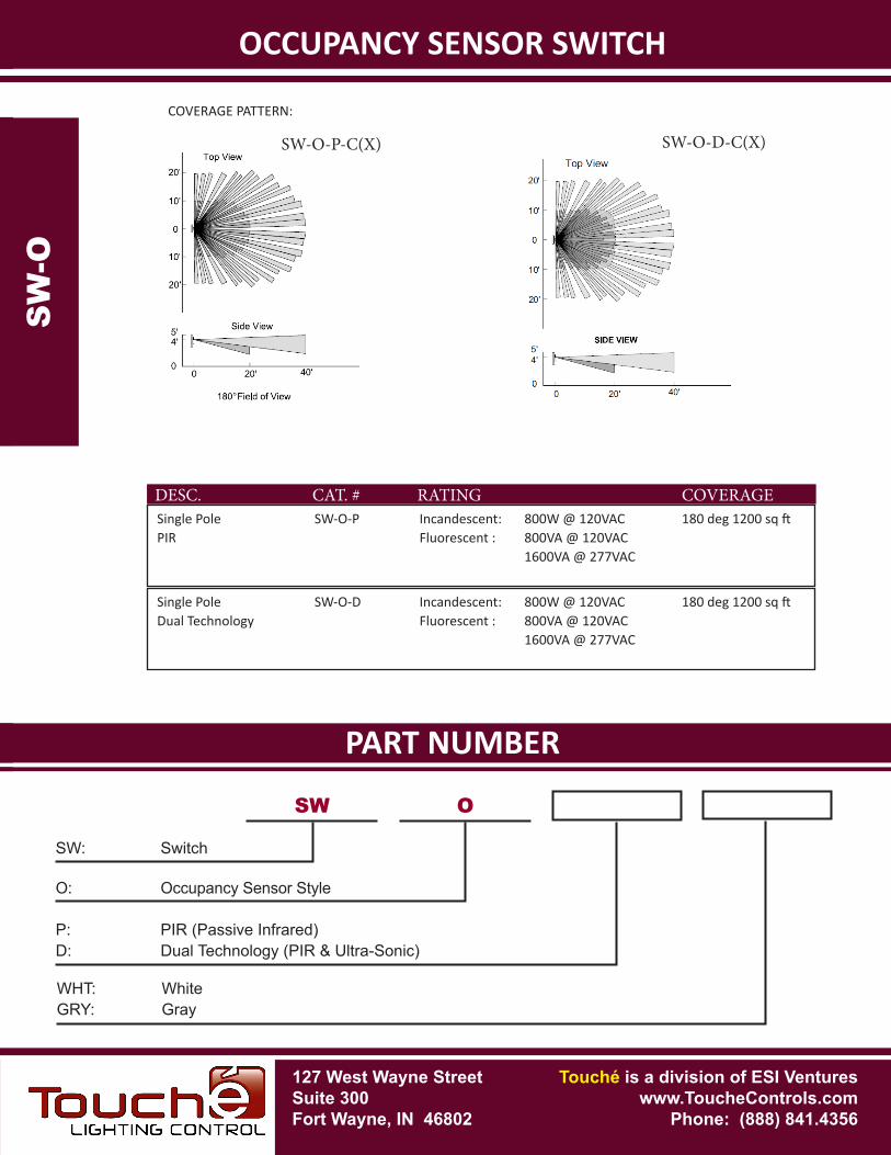
COVERAGE PATTERN:
SW-O-P-C(X)
Single Pole SW-O-P Incandescent: 800W @ 120VAC 180 deg 1200 sq ft PIR Fluorescent : 800VA @ 120VAC 1600VA @ 277VAC
DESC. CAT. # RATING COVERAGE
Single Pole SW-O-D Incandescent: 800W @ 120VAC 180 deg 1200 sq ft Dual Technology Fluorescent : 800VA @ 120VAC 1600VA @ 277VAC
SW-O-D-C(X)
SW
-O
SW
-O
SW: Switch
SW O
O: Occupancy Sensor Style
P: PIR (Passive Infrared)D: Dual Technology (PIR & Ultra-Sonic)
WHT: WhiteGRY: Gray
127 West Wayne StreetSuite 300Fort Wayne, IN 46802
Touché is a division of ESI Ventureswww.ToucheControls.com
Phone: (888) 841.4356
127 West Wayne StreetSuite 300Fort Wayne, IN 46802
SPECIFICATIONS
Touché is a division of ESI Ventureswww.ToucheControls.com
Phone: (888) 841.4356
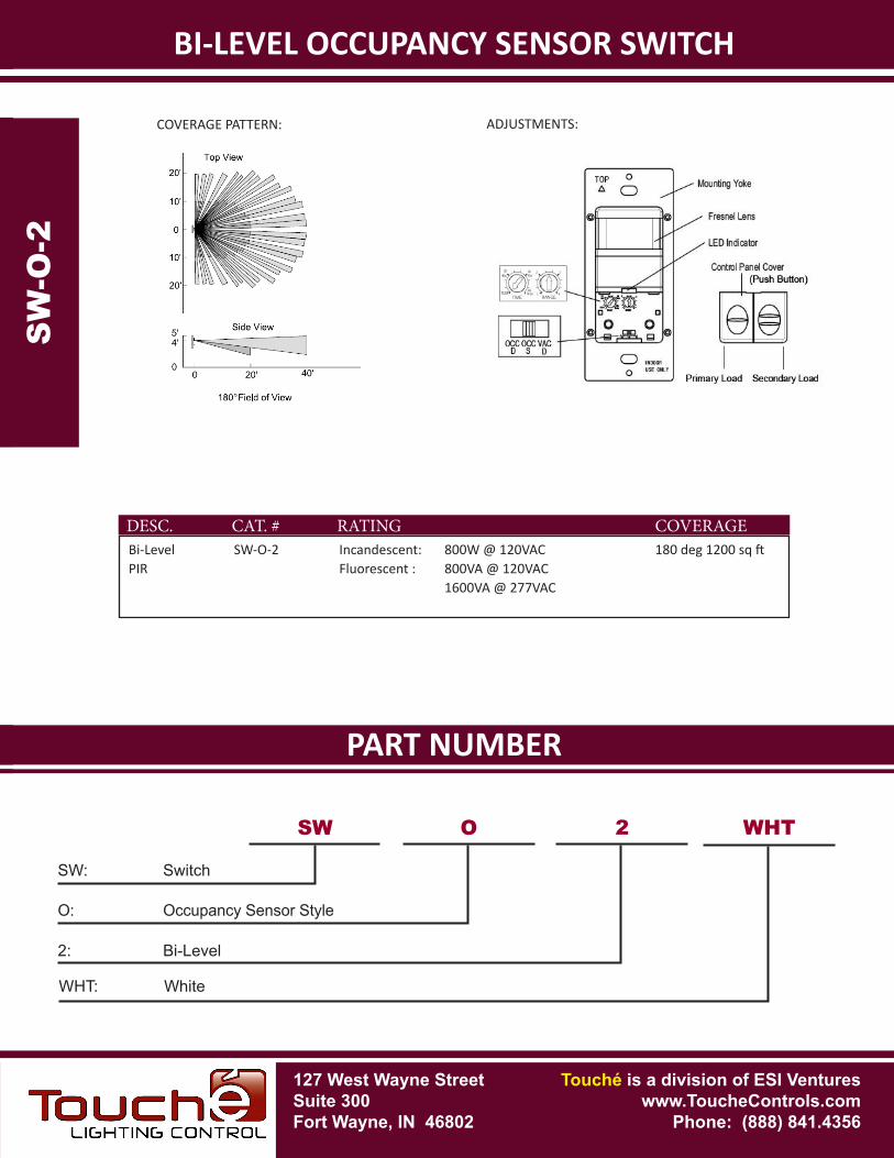
BI-LEVEL OCCUPANCY SENSOR SWITCH
Mounting Considerations: 1-1/2" Deep 4" Sq. Box with 1-G Ring or 1-G Masonry Box
Power Supply Voltage: 120/277VAC (Auto-Sensing)
Listings: UL773A
Ambient Temperature: 55º C (131º F)
Maximum Humidity: 10—90% Non-Condensing
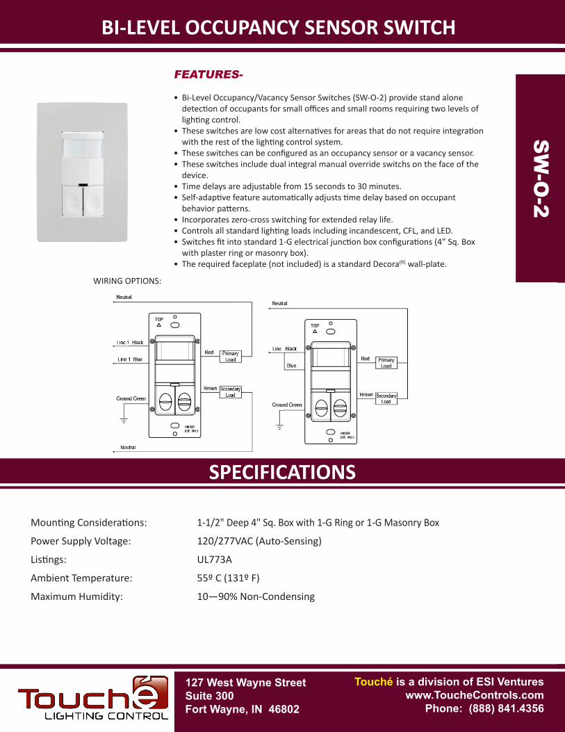
FEATURES-
• Bi-Level Occupancy/Vacancy Sensor Switches (SW-O-2) provide stand alone detection of occupants for small offices and small rooms requiring two levels of lighting control.
• These switches are low cost alternatives for areas that do not require integration with the rest of the lighting control system.
• These switches can be configured as an occupancy sensor or a vacancy sensor.• These switches include dual integral manual override switchs on the face of the
device. • Time delays are adjustable from 15 seconds to 30 minutes.• Self-adaptive feature automatically adjusts time delay based on occupant
behavior patterns.• Incorporates zero-cross switching for extended relay life.• Controls all standard lighting loads including incandescent, CFL, and LED.• Switches fit into standard 1-G electrical junction box configurations (4” Sq. Box
with plaster ring or masonry box). • The required faceplate (not included) is a standard Decora(R) wall-plate.
SW
-O-2
SW
-O-2
WIRING OPTIONS:
PART NUMBERSPECIFICATIONS
BI-LEVEL OCCUPANCY SENSOR SWITCH
COVERAGE PATTERN:
SW
-O-2
SW
-O-2
SW: Switch
SW O
O: Occupancy Sensor Style
2: Bi-Level
WHT: White
2
ADJUSTMENTS:
WHT
Bi-Level SW-O-2 Incandescent: 800W @ 120VAC 180 deg 1200 sq ft PIR Fluorescent : 800VA @ 120VAC 1600VA @ 277VAC
DESC. CAT. # RATING COVERAGE
127 West Wayne StreetSuite 300Fort Wayne, IN 46802
Touché is a division of ESI Ventureswww.ToucheControls.com
Phone: (888) 841.4356
127 West Wayne StreetSuite 300Fort Wayne, IN 46802
SPECIFICATIONS
Touché is a division of ESI Ventureswww.ToucheControls.com
Phone: (888) 841.4356
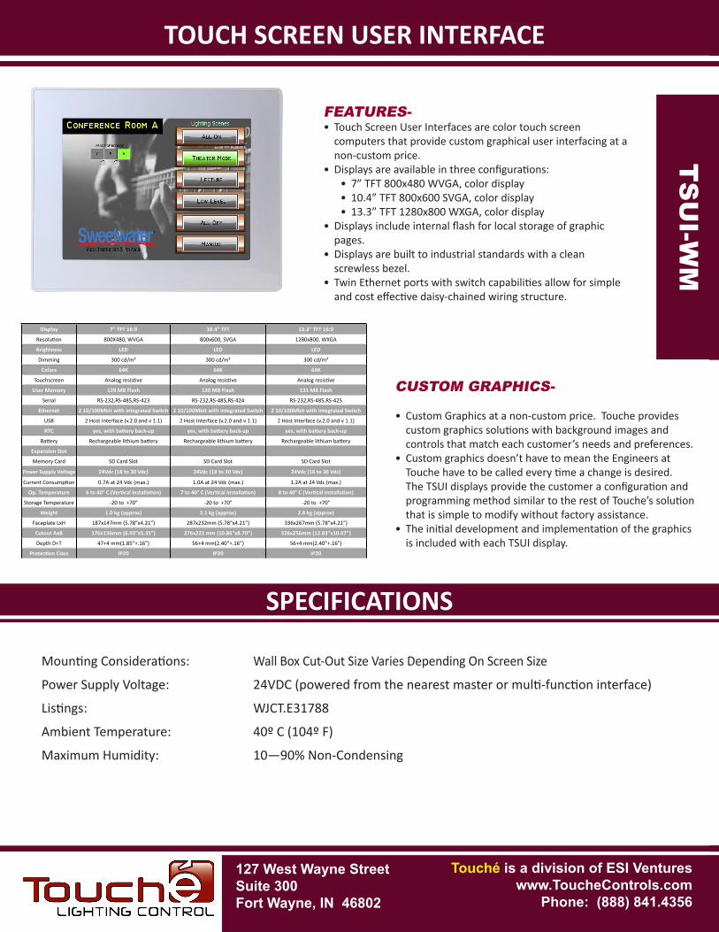
TOUCH SCREEN USER INTERFACE
Mounting Considerations: Wall Box Cut-Out Size Varies Depending On Screen Size
Power Supply Voltage: 24VDC (powered from the nearest master or multi-function interface)
Listings: WJCT.E31788
Ambient Temperature: 40º C (104º F)
Maximum Humidity: 10—90% Non-Condensing
FEATURES-• Touch Screen User Interfaces are color touch screen
computers that provide custom graphical user interfacing at a non-custom price.
• Displays are available in three configurations:• 7” TFT 800x480 WVGA, color display• 10.4” TFT 800x600 SVGA, color display• 13.3” TFT 1280x800 WXGA, color display
• Displays include internal flash for local storage of graphic pages.
• Displays are built to industrial standards with a clean screwless bezel.
• Twin Ethernet ports with switch capabilities allow for simple and cost effective daisy-chained wiring structure.
TOUCH SCREEN USER INTERFACE
Display 7” TFT 16:9 10.4” TFT 13.3” TFT 16:9
Resolution 800X480, WVGA 800x600, SVGA 1280x800, WXGA
Brightness LED LED LED
Dimming 300 cd/m² 300 cd/m² 300 cd/m²
Colors 64K 64K 64K
Touchscreen Analog resistive Analog resistive Analog resistive
User Memory 129 MB Flash 130 MB Flash 131 MB Flash
Serial RS-232,RS-485,RS-423 RS-232,RS-485,RS-424 RS-232,RS-485,RS-425
Ethernet 2 10/100Mbit with integrated Switch 2 10/100Mbit with integrated Switch 2 10/100Mbit with integrated Switch
USB 2 Host Interface (v.2.0 and v 1.1) 2 Host Interface (v.2.0 and v 1.1) 2 Host Interface (v.2.0 and v 1.1)
RTC yes, with battery back-up yes, with battery back-up yes, with battery back-up
Battery Rechargeable lithium battery Rechargeable lithium battery Rechargeable lithium battery
Expansion Slot
Memory Card SD Card Slot SD Card Slot SD Card Slot
Power Supply Voltage 24Vdc (18 to 30 Vdc) 24Vdc (18 to 30 Vdc) 24Vdc (18 to 30 Vdc)
Current Consumption 0.7A at 24 Vdc (max.) 1.0A at 24 Vdc (max.) 1.2A at 24 Vdc (max.)
Op. Temperature 6 to 40° C (Vertical installation) 7 to 40° C (Vertical installation) 8 to 40° C (Vertical installation)
Storage Temperature -20 to +70° -20 to +70° -20 to +70°
Weight 1.0 kg (approx) 2.1 kg (approx) 2.8 kg (approx)
Faceplate LxH 187x147mm (5.78”x4.21”) 287x232mm (5.78”x4.21”) 336x267mm (5.78”x4.21”)
Cutout AxB 176x136mm (6.93”x5.35”) 276x221 mm (10.86”x8.70”) 326x256mm (12.83”x10.07”)
Depth D+T 47+4 mm(1.85”+.16”) 56+4 mm(2.40”+.16”) 56+4 mm(2.40”+.16”)
Protection Class IP20 IP20 IP20
TS
UI-
WM
TS
UI-W
M
CUSTOM GRAPHICS-
• Custom Graphics at a non-custom price. Touche provides custom graphics solutions with background images and controls that match each customer’s needs and preferences.
• Custom graphics doesn’t have to mean the Engineers at Touche have to be called every time a change is desired. The TSUI displays provide the customer a configuration and programming method similar to the rest of Touche’s solution that is simple to modify without factory assistance.
• The initial development and implementation of the graphics is included with each TSUI display.
PART NUMBERSPECIFICATIONS
TOUCH SCREEN USER INTERFACET
SU
I-W
M
TS
UI-W
M
TSUI: Touchscreen User Interface
TSUI WM
WM: Wall Mounted (Flush)
7.0: Screen Size - 7.0 (Diagonal Inches)10.4: Screen Size - 10.4 (Diagonal Inches)13.3: Screen Size - 13.3 (Diagonal Inches)
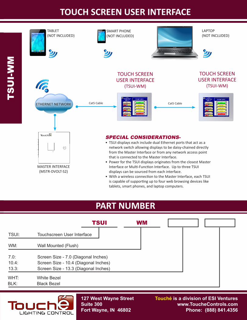
SPECIAL CONSIDERATIONS-• TSUI displays each include dual Ethernet ports that act as a
network switch allowing displays to be daisy-chained directly from the Master Interface or from any network access point that is connected to the Master Interface.
• Power for the TSUI displays originates from the closest Master Interface or Multi-Function Interface. Up to three TSUI displays can be sourced from each interface.
• With a wireless connection to the Master Interface, each TSUI is capable of supporting up to four web browsing devices like tablets, smart phones, and laptop computers.
WHT: White BezelBLK: Black Bezel
127 West Wayne StreetSuite 300Fort Wayne, IN 46802
Touché is a division of ESI Ventureswww.ToucheControls.com
Phone: (888) 841.4356
ETHERNET NETWORK
MASTER INTERFACE(MSTR-DVOLT-S2)
Cat5 Cable Cat5 Cable
TOUCH SCREENUSER INTERFACE
(TSUI-WM)
TOUCH SCREENUSER INTERFACE
(TSUI-WM)
TABLET(NOT INCLUDED)
SMART PHONE(NOT INCLUDED)
LAPTOP(NOT INCLUDED)
127 West Wayne StreetSuite 300Fort Wayne, IN 46802
SPECIFICATIONS
Touché is a division of ESI Ventureswww.ToucheControls.com
Phone: (888) 841.4356
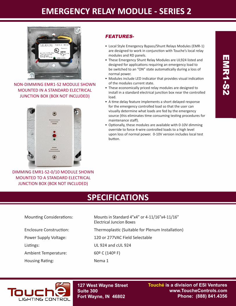
EMERGENCY RELAY MODULE - SERIES 2
Mounting Considerations: Mounts in Standard 4”x4” or 4-11/16”x4-11/16” Electrical Juncion Boxes
Enclosure Construction: Thermoplastic (Suitable for Plenum Installation)
Power Supply Voltage: 120 or 277VAC Field Selectable
Listings: UL 924 and cUL 924
Ambient Temperature: 60º C (140º F)
Housing Rating: Nema 1
EMERGENCY RELAY MODULE - SERIES 2
EM
R1-
S2E
MR
1-S2
FEATURES-
• Local Style Emergency Bypass/Shunt Relays Modules (EMR-1) are designed to work in conjunction with Touche’s local relay modules and RD panels.
• These Emergency Shunt Relay Modules are UL924 listed and designed for applications requiring an emergency load to be switched to an “ON” state automatically during a loss of normal power.
• Modules include LED indicator that provides visual indication of the modules current state.
• These economically priced relay modules are designed to install in a standard electrical junction box near the controlled load.
• A time delay feature implements a short delayed response for the emergency controlled load so that the user can visually determine what loads are fed by the emergency source (this eliminates time consuming testing procedures for maintenance staff).
• Optionally, these modules are available with 0-10V dimming override to force 4-wire controlled loads to a high level upon loss of normal power. 0-10V version includes local test button.
NON-DIMMING EMR1-S2 MODULE SHOWN MOUNTED IN A STANDARD ELECTRICAL JUNCTION BOX (BOX NOT INCLUDED)
DIMMING EMR1-S2-0/10 MODULE SHOWN MOUNTED TO A STANDARD ELECTRICAL
JUNCTION BOX (BOX NOT INCLUDED)
PART NUMBERSPECIFICATIONS
EMERGENCY RELAY MODULE - SERIES 2E
MR
1-S
2EM
R1-S
2
EMR1 S2
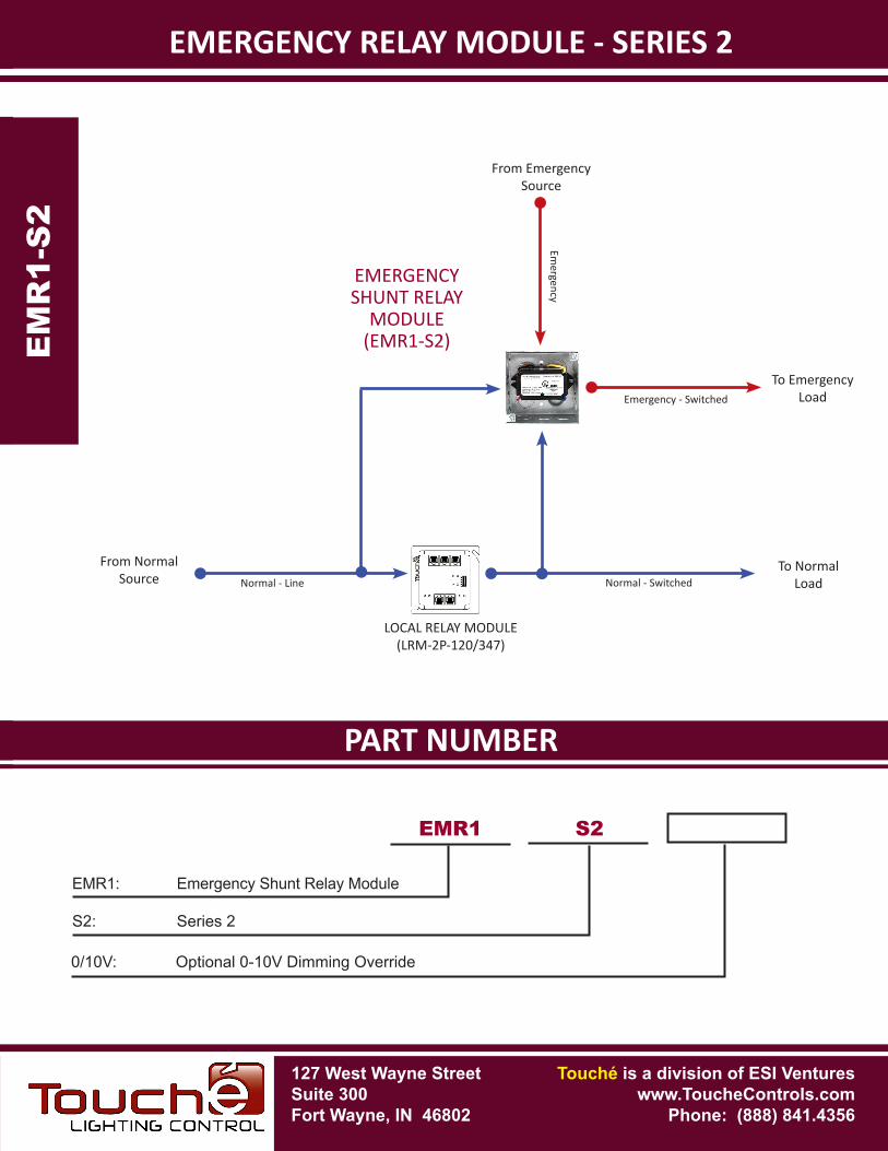
EMR1: Emergency Shunt Relay Module
S2: Series 2
0/10V: Optional 0-10V Dimming Override
LOCAL RELAY MODULE(LRM-2P-120/347)
To NormalLoad
To EmergencyLoad
From NormalSource
From EmergencySource
EMERGENCY SHUNT RELAY
MODULE(EMR1-S2)
127 West Wayne StreetSuite 300Fort Wayne, IN 46802
Touché is a division of ESI Ventureswww.ToucheControls.com
Phone: (888) 841.4356
Emergency
Emergency - Switched
Normal - SwitchedNormal - Line
127 West Wayne StreetSuite 300Fort Wayne, IN 46802
SPECIFICATIONS
Touché is a division of ESI Ventureswww.ToucheControls.com
Phone: (888) 841.4356
EMERGENCY RELAY MODULE - LOCAL STYLE
Mounting Considerations: 1/2” K.O. (Knock Out) of Any Standard 4” Square Electrical Box
Power Supply Voltage: 120 or 277VAC
Listings: UL 924 and cUL 924
Ambient Temperature: 60º C (140º F)
Housing Rating: Nema 1
EMERGENCY RELAY MODULE - LOCAL STYLE
EM
R-1
EM
R-1
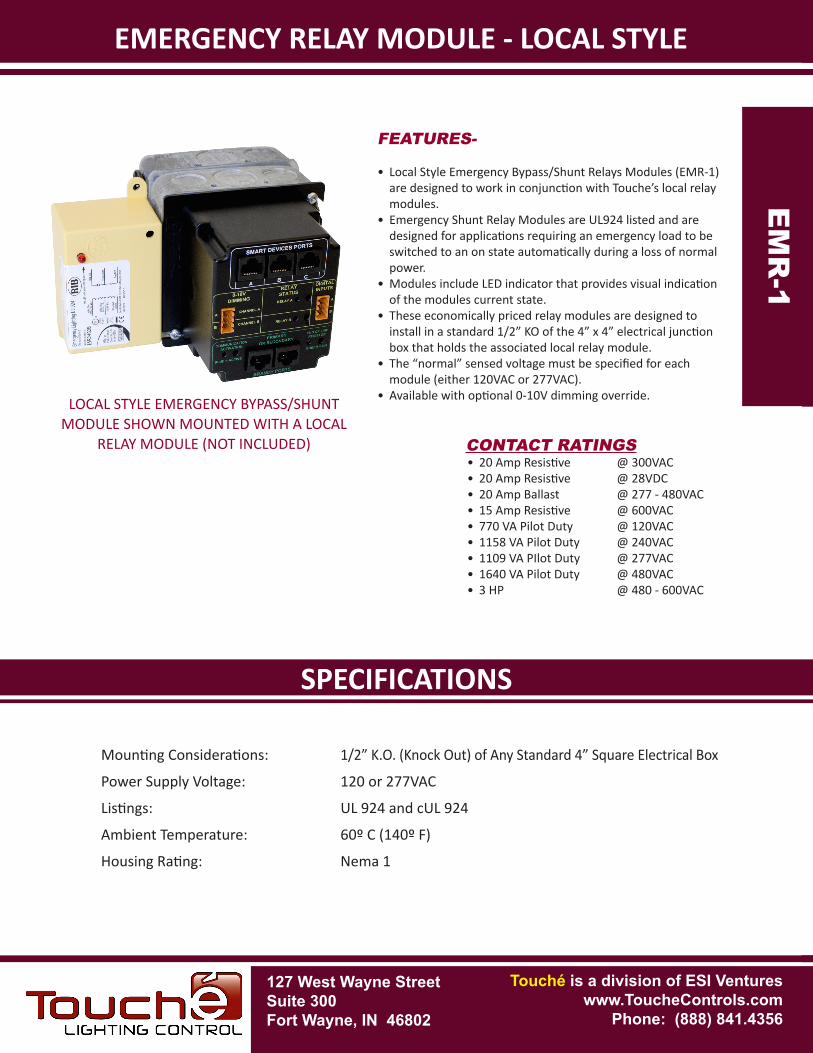
FEATURES-
• Local Style Emergency Bypass/Shunt Relays Modules (EMR-1) are designed to work in conjunction with Touche’s local relay modules.
• Emergency Shunt Relay Modules are UL924 listed and are designed for applications requiring an emergency load to be switched to an on state automatically during a loss of normal power.
• Modules include LED indicator that provides visual indication of the modules current state.
• These economically priced relay modules are designed to install in a standard 1/2” KO of the 4” x 4” electrical junction box that holds the associated local relay module.
• The “normal” sensed voltage must be specified for each module (either 120VAC or 277VAC).
• Available with optional 0-10V dimming override.
CONTACT RATINGS• 20 Amp Resistive @ 300VAC• 20 Amp Resistive @ 28VDC• 20 Amp Ballast @ 277 - 480VAC• 15 Amp Resistive @ 600VAC• 770 VA Pilot Duty @ 120VAC• 1158 VA Pilot Duty @ 240VAC• 1109 VA PIlot Duty @ 277VAC• 1640 VA Pilot Duty @ 480VAC• 3 HP @ 480 - 600VAC
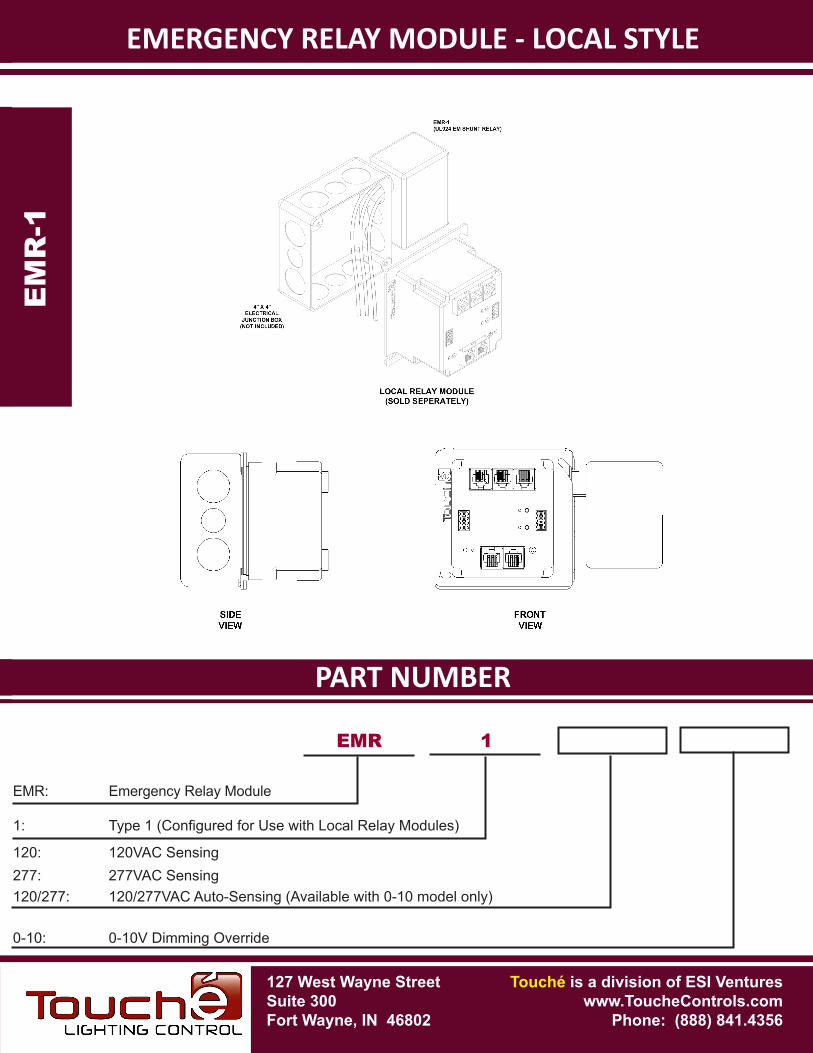
LOCAL STYLE EMERGENCY BYPASS/SHUNT MODULE SHOWN MOUNTED WITH A LOCAL
RELAY MODULE (NOT INCLUDED)
PART NUMBERSPECIFICATIONS
EMERGENCY RELAY MODULE - LOCAL STYLEE
MR
-1
EM
R-1
EMR 1
EMR: Emergency Relay Module
1: Type1(ConfiguredforUsewithLocalRelayModules)
120: 120VAC Sensing277: 277VAC Sensing
0-10: 0-10V Dimming Override
120/277: 120/277VAC Auto-Sensing (Available with 0-10 model only)
127 West Wayne StreetSuite 300Fort Wayne, IN 46802
Touché is a division of ESI Ventureswww.ToucheControls.com
Phone: (888) 841.4356
127 West Wayne StreetSuite 300Fort Wayne, IN 46802
SPECIFICATIONS
Touché is a division of ESI Ventureswww.ToucheControls.com
Phone: (888) 841.4356
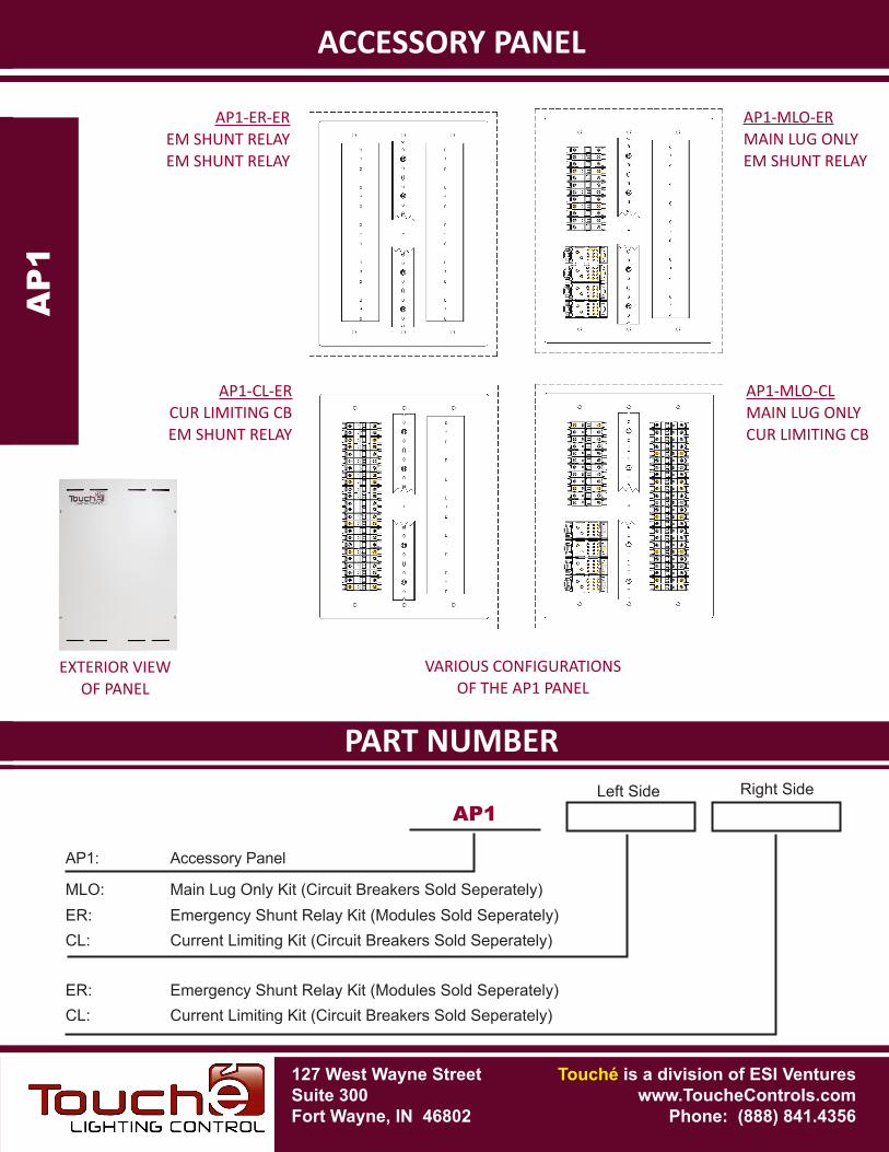
ACCESSORY PANEL
FEATURES-
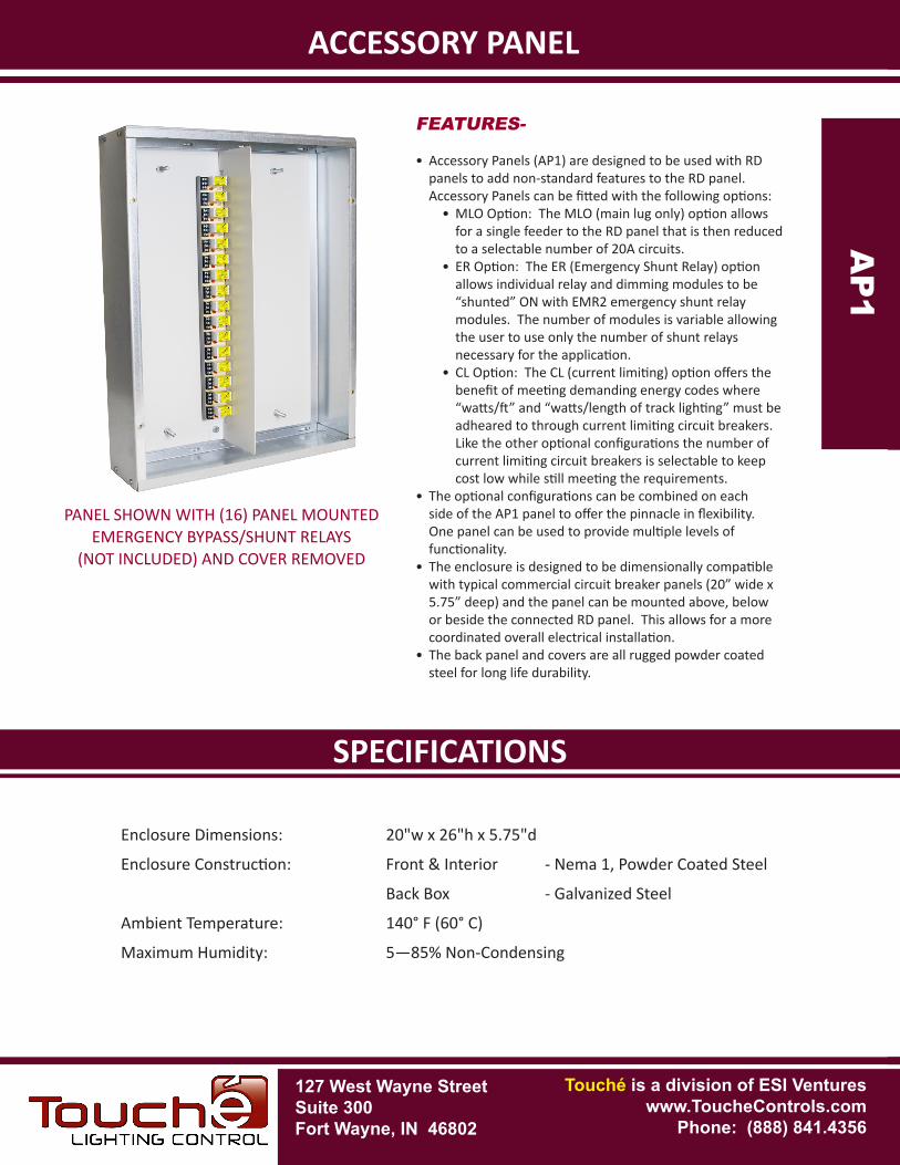
• Accessory Panels (AP1) are designed to be used with RD panels to add non-standard features to the RD panel. Accessory Panels can be fitted with the following options:
• MLO Option: The MLO (main lug only) option allows for a single feeder to the RD panel that is then reduced to a selectable number of 20A circuits.
• ER Option: The ER (Emergency Shunt Relay) option allows individual relay and dimming modules to be “shunted” ON with EMR2 emergency shunt relay modules. The number of modules is variable allowing the user to use only the number of shunt relays necessary for the application.
• CL Option: The CL (current limiting) option offers the benefit of meeting demanding energy codes where “watts/ft” and “watts/length of track lighting” must be adheared to through current limiting circuit breakers. Like the other optional configurations the number of current limiting circuit breakers is selectable to keep cost low while still meeting the requirements.
• The optional configurations can be combined on each side of the AP1 panel to offer the pinnacle in flexibility. One panel can be used to provide multiple levels of functionality.
• The enclosure is designed to be dimensionally compatible with typical commercial circuit breaker panels (20” wide x 5.75” deep) and the panel can be mounted above, below or beside the connected RD panel. This allows for a more coordinated overall electrical installation.
• The back panel and covers are all rugged powder coated steel for long life durability.
Enclosure Dimensions: 20"w x 26"h x 5.75"d
Enclosure Construction: Front & Interior - Nema 1, Powder Coated Steel
Back Box - Galvanized Steel
Ambient Temperature: 140° F (60° C)
Maximum Humidity: 5—85% Non-Condensing
ACCESSORY PANEL
AP
1AP
1
PANEL SHOWN WITH (16) PANEL MOUNTED EMERGENCY BYPASS/SHUNT RELAYS
(NOT INCLUDED) AND COVER REMOVED
PART NUMBERSPECIFICATIONS
ACCESSORY PANELA
P1A
P1
AP1
AP1: Accessory Panel
Left Side
ER: Emergency Shunt Relay Kit (Modules Sold Seperately)CL: Current Limiting Kit (Circuit Breakers Sold Seperately)
ER: Emergency Shunt Relay Kit (Modules Sold Seperately)CL: Current Limiting Kit (Circuit Breakers Sold Seperately)
Right Side
MLO: Main Lug Only Kit (Circuit Breakers Sold Seperately)
127 West Wayne StreetSuite 300Fort Wayne, IN 46802
Touché is a division of ESI Ventureswww.ToucheControls.com
Phone: (888) 841.4356
EXTERIOR VIEWOF PANEL
VARIOUS CONFIGURATIONS OF THE AP1 PANEL
AP1-MLO-ERMAIN LUG ONLYEM SHUNT RELAY
AP1-MLO-CLMAIN LUG ONLYCUR LIMITING CB
AP1-CL-ERCUR LIMITING CBEM SHUNT RELAY
AP1-ER-EREM SHUNT RELAYEM SHUNT RELAY
127 West Wayne StreetSuite 300Fort Wayne, IN 46802
SPECIFICATIONS
Touché is a division of ESI Ventureswww.ToucheControls.com
Phone: (888) 841.4356
EMERGENCY RELAY MODULE - PANEL MOUNTED
Mounting Considerations: Track Mounted Inside EMRP Enclosure
Power Supply Voltage: 120 or 277VAC
Listings: UL 924 and cUL 924
Ambient Temperature: 60º C (140º F)
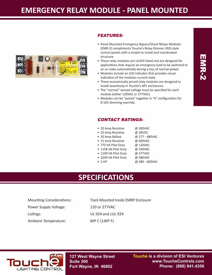
FEATURES-
• Panel Mounted Emergency Bypass/Shunt Relays Modules (EMR-2) compliments Touche’s Relay-Dimmer (RD) style control panels with a simple to install and coordinated structure.
• These relay modules are UL924 listed and are designed for applications that require an emergency load to be switched to an on state automatically during a loss of normal power.
• Modules include an LED indicator that provides visual indication of the modules current state.
• These economically priced relay modules are designed to install seamlessly in Touche’s AP1 enclosures.
• The “normal” sensed voltage must be specified for each module (either 120VAC or 277VAC).
• Modules can be “paired” together in “A” configuration for 0-10V dimming override.
CONTACT RATINGS-
• 20 Amp Resistive @ 300VAC• 20 Amp Resistive @ 28VDC• 20 Amp Ballast @ 277 - 480VAC• 15 Amp Resistive @ 600VAC• 770 VA Pilot Duty @ 120VAC• 1158 VA Pilot Duty @ 240VAC• 1109 VA Pilot Duty @ 277VAC• 1640 VA Pilot Duty @ 480VAC• 3 HP @ 480 - 600VAC
EMERGENCY RELAY MODULE - PANEL MOUNTED
EM
R-2
EM
R-2
PART NUMBERSPECIFICATIONS
EMERGENCY RELAY MODULE - PANEL MOUNTEDE
MR
-2
EM
R-2
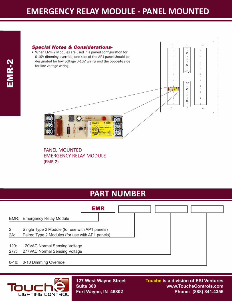
Special Notes & Considerations-• When EMR-2 Modules are used in a paired configuration for
0-10V dimming override, one side of the AP1 panel should be designated for low voltage 0-10V wiring and the opposite side for line voltage wiring.
EMR
EMR: Emergency Relay Module
2: Single Type 2 Module (for use with AP1 panels)2A: Paired Type 2 Modules (for use with AP1 panels)
120: 120VAC Normal Sensing Voltage277: 277VAC Normal Sensing Voltage
0-10: 0-10 Dimming Override
127 West Wayne StreetSuite 300Fort Wayne, IN 46802
Touché is a division of ESI Ventureswww.ToucheControls.com
Phone: (888) 841.4356
PANEL MOUNTED EMERGENCY RELAY MODULE(EMR-2)
127 West Wayne StreetSuite 300Fort Wayne, IN 46802
SPECIFICATIONS
Touché is a division of ESI Ventureswww.ToucheControls.com
Phone: (888) 841.4356
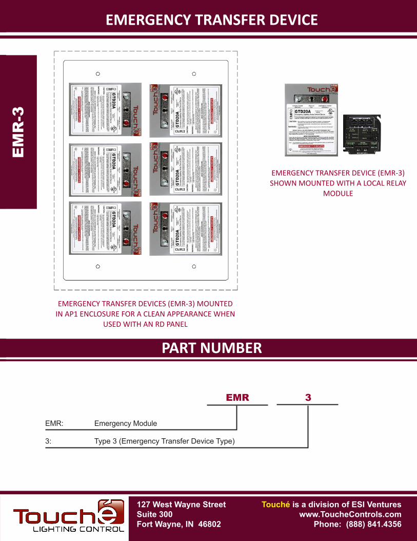
EMERGENCY TRANSFER DEVICE
Mounting Considerations: Device can be in any Nema 1 Environment or in AP1 Enclsoure for a Clean Appearance when Multiple ERM-3 Modules are Used
Power Supply Voltage: 120 or 277VAC
Listings: UL 1008 and CSA 22.2 No. 178
Ambient Temperature: 55º C (131º F)
Housing Rating: Nema 1
EMERGENCY TRANSFER DEVICE
EM
R-3
EM
R-3
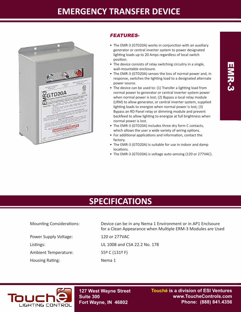
FEATURES-
• The EMR-3 (GTD20A) works in conjunction with an auxiliary generator or central inverter system to power designated lighting loads up to 20 Amps regardless of local switch position.
• The device consists of relay switching circuitry in a single, wall-mountable enclosure.
• The EMR-3 (GTD20A) senses the loss of normal power and, in response, switches the lighting load to a designated alternate power source.
• The device can be used to: (1) Transfer a lighting load from normal power to generator or central inverter system power when normal power is lost; (2) Bypass a local relay module (LRM) to allow generator, or central inverter system, supplied lighting loads to energize when normal power is lost; (3) Bypass an RD Panel relay or dimming module and prevent backfeed to allow lighting to energize at full brightness when normal power is lost.
• The EMR-3 (GTD20A) includes three dry form C contacts, which allows the user a wide variety of wiring options.
• For additional applications and information, contact the factory.
• The EMR-3 (GTD20A) is suitable for use in indoor and damp locations.
• The EMR-3 (GTD20A) is voltage auto-sensing (120 or 277VAC).
PART NUMBERSPECIFICATIONS
EMERGENCY TRANSFER DEVICEE
MR
-3
EM
R-3
EMR 3
EMR: Emergency Module
3: Type 3 (Emergency Transfer Device Type)
127 West Wayne StreetSuite 300Fort Wayne, IN 46802
Touché is a division of ESI Ventureswww.ToucheControls.com
Phone: (888) 841.4356
EMERGENCY TRANSFER DEVICE (EMR-3) SHOWN MOUNTED WITH A LOCAL RELAY
MODULE
EMERGENCY TRANSFER DEVICES (EMR-3) MOUNTED IN AP1 ENCLOSURE FOR A CLEAN APPEARANCE WHEN
USED WITH AN RD PANEL
127 West Wayne StreetSuite 300Fort Wayne, IN 46802
SPECIFICATIONS
Touché is a division of ESI Ventureswww.ToucheControls.com
Phone: (888) 841.4356
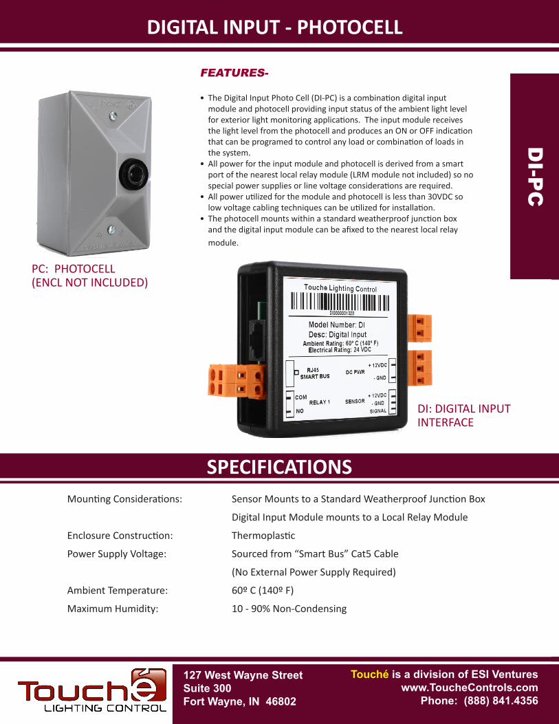
DIGITAL INPUT - PHOTOCELL
FEATURES-
• The Digital Input Photo Cell (DI-PC) is a combination digital input module and photocell providing input status of the ambient light level for exterior light monitoring applications. The input module receives the light level from the photocell and produces an ON or OFF indication that can be programed to control any load or combination of loads in the system.
• All power for the input module and photocell is derived from a smart port of the nearest local relay module (LRM module not included) so no special power supplies or line voltage considerations are required.
• All power utilized for the module and photocell is less than 30VDC so low voltage cabling techniques can be utilized for installation.
• The photocell mounts within a standard weatherproof junction box and the digital input module can be afixed to the nearest local relay module.
Mounting Considerations: Sensor Mounts to a Standard Weatherproof Junction Box
Digital Input Module mounts to a Local Relay Module
Enclosure Construction: Thermoplastic
Power Supply Voltage: Sourced from “Smart Bus” Cat5 Cable
(No External Power Supply Required)
Ambient Temperature: 60º C (140º F)
Maximum Humidity: 10 - 90% Non-Condensing
DI-
PC
DI-P
C
PC: PHOTOCELL(ENCL NOT INCLUDED)
DI: DIGITAL INPUTINTERFACE
PART NUMBERSPECIFICATIONS
DIGITAL INPUT - PHOTOCELLD
I-P
C
DI-P
CDI: Digital Input
DI
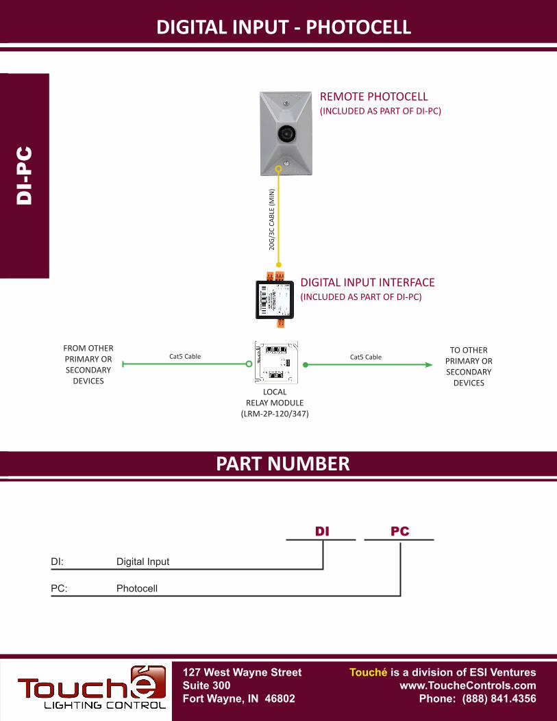
TO OTHERPRIMARY OR SECONDARY
DEVICES
Cat5 CableCat5 CableFROM OTHERPRIMARY OR SECONDARY
DEVICES
REMOTE PHOTOCELL(INCLUDED AS PART OF DI-PC)
20G/
3C C
ABLE
(MIN
)
PC: Photocell
PC
DIGITAL INPUT INTERFACE(INCLUDED AS PART OF DI-PC)
127 West Wayne StreetSuite 300Fort Wayne, IN 46802
Touché is a division of ESI Ventureswww.ToucheControls.com
Phone: (888) 841.4356
LOCALRELAY MODULE
(LRM-2P-120/347)
127 West Wayne StreetSuite 300Fort Wayne, IN 46802
SPECIFICATIONS
Touché is a division of ESI Ventureswww.ToucheControls.com
Phone: (888) 841.4356
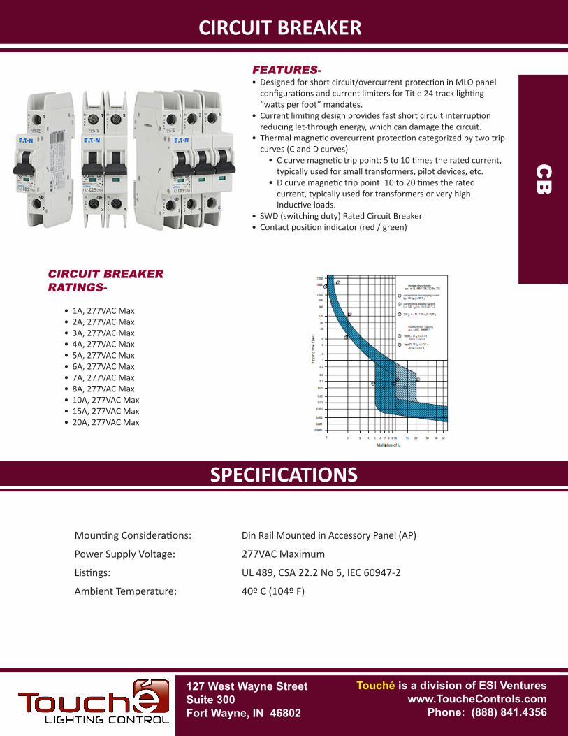
CIRCUIT BREAKER
Mounting Considerations: Din Rail Mounted in Accessory Panel (AP)
Power Supply Voltage: 277VAC Maximum
Listings: UL 489, CSA 22.2 No 5, IEC 60947-2
Ambient Temperature: 40º C (104º F)
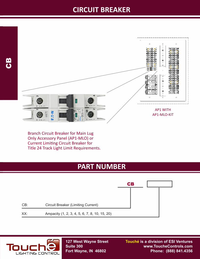
FEATURES-• Designed for short circuit/overcurrent protection in MLO panel
configurations and current limiters for Title 24 track lighting “watts per foot” mandates.
• Current limiting design provides fast short circuit interruption reducing let-through energy, which can damage the circuit.
• Thermal magnetic overcurrent protection categorized by two trip curves (C and D curves)
• C curve magnetic trip point: 5 to 10 times the rated current, typically used for small transformers, pilot devices, etc.
• D curve magnetic trip point: 10 to 20 times the rated current, typically used for transformers or very high inductive loads.
• SWD (switching duty) Rated Circuit Breaker• Contact position indicator (red / green)
CIRCUIT BREAKER
CB
CB
CIRCUIT BREAKER RATINGS-
• 1A, 277VAC Max • 2A, 277VAC Max• 3A, 277VAC Max• 4A, 277VAC Max• 5A, 277VAC Max• 6A, 277VAC Max• 7A, 277VAC Max• 8A, 277VAC Max• 10A, 277VAC Max• 15A, 277VAC Max• 20A, 277VAC Max
PART NUMBERSPECIFICATIONS
CIRCUIT BREAKERC
B
CB
CB
CB: Circuit Breaker (Limiting Current)
XX: Ampacity (1, 2, 3, 4, 5, 6, 7, 8, 10, 15, 20)
127 West Wayne StreetSuite 300Fort Wayne, IN 46802
Touché is a division of ESI Ventureswww.ToucheControls.com
Phone: (888) 841.4356
Branch Circuit Breaker for Main Lug Only Accessory Panel (AP1-MLO) or Current Limiting Circuit Breaker for Title 24 Track Light Limit Requirements.
AP1 WITHAP1-MLO-KIT
127 West Wayne StreetSuite 300Fort Wayne, IN 46802
SPECIFICATIONS
Touché is a division of ESI Ventureswww.ToucheControls.com
Phone: (888) 841.4356
SMART DIGITAL OUTPUT - OCC REPEATER
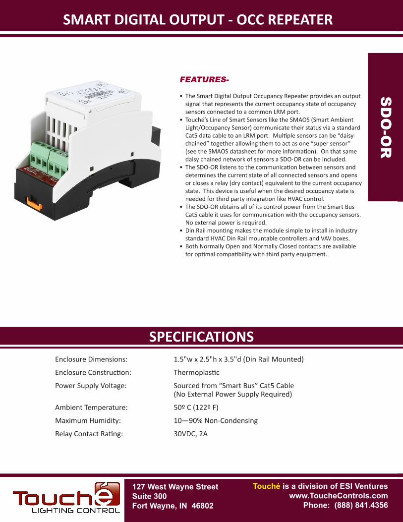
FEATURES-
• The Smart Digital Output Occupancy Repeater provides an output signal that represents the current occupancy state of occupancy sensors connected to a common LRM port.
• Touché’s Line of Smart Sensors like the SMAOS (Smart Ambient Light/Occupancy Sensor) communicate their status via a standard Cat5 data cable to an LRM port. Multiple sensors can be “daisy-chained” together allowing them to act as one “super sensor” (see the SMAOS datasheet for more information). On that same daisy chained network of sensors a SDO-OR can be included.
• The SDO-OR listens to the communication between sensors and determines the current state of all connected sensors and opens or closes a relay (dry contact) equivalent to the current occupancy state. This device is useful when the desired occupancy state is needed for third party integration like HVAC control.
• The SDO-OR obtains all of its control power from the Smart Bus Cat5 cable it uses for communication with the occupancy sensors. No external power is required.
• Din Rail mounting makes the module simple to install in industry standard HVAC Din Rail mountable controllers and VAV boxes.
• Both Normally Open and Normally Closed contacts are available for optimal compatibility with third party equipment.
SD
O-O
R
SD
O-O
R
Enclosure Dimensions: 1.5"w x 2.5"h x 3.5"d (Din Rail Mounted)
Enclosure Construction: Thermoplastic
Power Supply Voltage: Sourced from “Smart Bus” Cat5 Cable (No External Power Supply Required)
Ambient Temperature: 50º C (122º F)
Maximum Humidity: 10—90% Non-Condensing
Relay Contact Rating: 30VDC, 2A
PART NUMBERSPECIFICATIONS
SMART DIGITAL OUTPUT - OCC REPEATERS
DO
-OR
SD
O-O
R
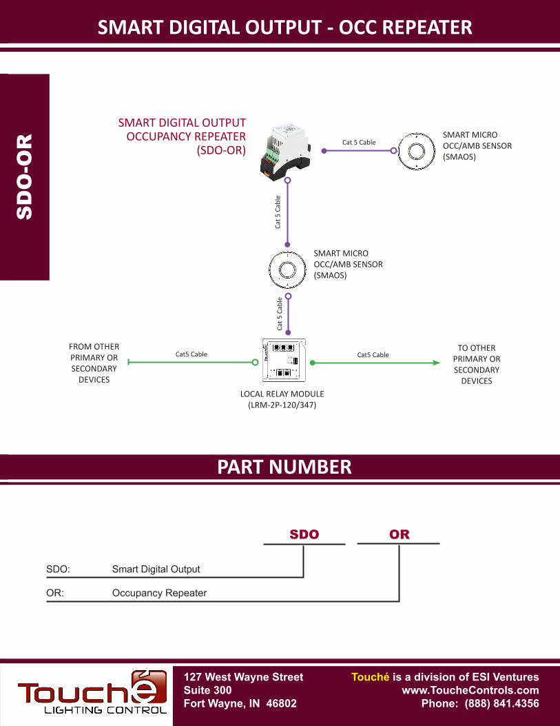
SMART DIGITAL OUTPUTOCCUPANCY REPEATER
(SDO-OR)
LOCAL RELAY MODULE(LRM-2P-120/347)
Cat 5
Cab
le
TO OTHERPRIMARY OR SECONDARY
DEVICES
Cat5 Cable
SDO OR
SDO: Smart Digital Output
OR: Occupancy Repeater
Cat 5
Cab
le
Cat 5 Cable
Cat5 CableFROM OTHERPRIMARY OR SECONDARY
DEVICES
127 West Wayne StreetSuite 300Fort Wayne, IN 46802
Touché is a division of ESI Ventureswww.ToucheControls.com
Phone: (888) 841.4356
SMART MICRO OCC/AMB SENSOR(SMAOS)
SMART MICRO OCC/AMB SENSOR(SMAOS)
127 West Wayne StreetSuite 300Fort Wayne, IN 46802
SPECIFICATIONS
Touché is a division of ESI Ventureswww.ToucheControls.com
Phone: (888) 841.4356
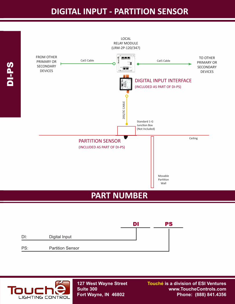
DIGITAL INPUT - PARTITION SENSOR
FEATURES-
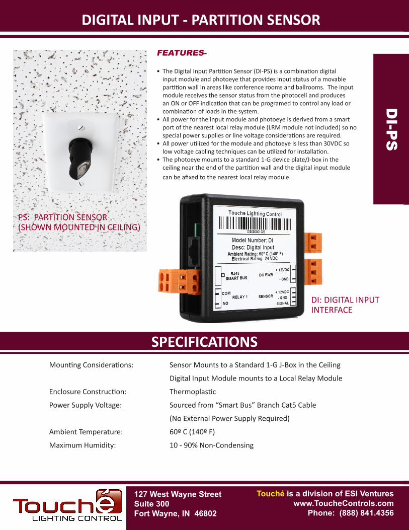
• The Digital Input Partition Sensor (DI-PS) is a combination digital input module and photoeye that provides input status of a movable partition wall in areas like conference rooms and ballrooms. The input module receives the sensor status from the photocell and produces an ON or OFF indication that can be programed to control any load or combination of loads in the system.
• All power for the input module and photoeye is derived from a smart port of the nearest local relay module (LRM module not included) so no special power supplies or line voltage considerations are required.
• All power utilized for the module and photoeye is less than 30VDC so low voltage cabling techniques can be utilized for installation.
• The photoeye mounts to a standard 1-G device plate/J-box in the ceiling near the end of the partition wall and the digital input module can be afixed to the nearest local relay module.
Mounting Considerations: Sensor Mounts to a Standard 1-G J-Box in the Ceiling
Digital Input Module mounts to a Local Relay Module
Enclosure Construction: Thermoplastic
Power Supply Voltage: Sourced from “Smart Bus” Branch Cat5 Cable
(No External Power Supply Required)
Ambient Temperature: 60º C (140º F)
Maximum Humidity: 10 - 90% Non-Condensing
DI-
PS
DI-P
S
DI: DIGITAL INPUTINTERFACE
PS: PARTITION SENSOR(SHOWN MOUNTED IN CEILING)
PART NUMBERSPECIFICATIONS
DIGITAL INPUT - PARTITION SENSORD
I-P
S
DI-P
SDI: Digital Input
DI
TO OTHERPRIMARY OR SECONDARY
DEVICES
Cat5 CableCat5 CableFROM OTHERPRIMARY OR SECONDARY
DEVICES
PARTITION SENSOR(INCLUDED AS PART OF DI-PS)
20G/
3C C
ABLE
PS: Partition Sensor
PS
DIGITAL INPUT INTERFACE(INCLUDED AS PART OF DI-PS)
Ceiling
MovablePartition
Wall
Standard 1-GJunction Box(Not Included)
127 West Wayne StreetSuite 300Fort Wayne, IN 46802
Touché is a division of ESI Ventureswww.ToucheControls.com
Phone: (888) 841.4356
LOCALRELAY MODULE
(LRM-2P-120/347)
127 West Wayne StreetSuite 300Fort Wayne, IN 46802
SPECIFICATIONS
Touché is a division of ESI Ventureswww.ToucheControls.com
Phone: (888) 841.4356
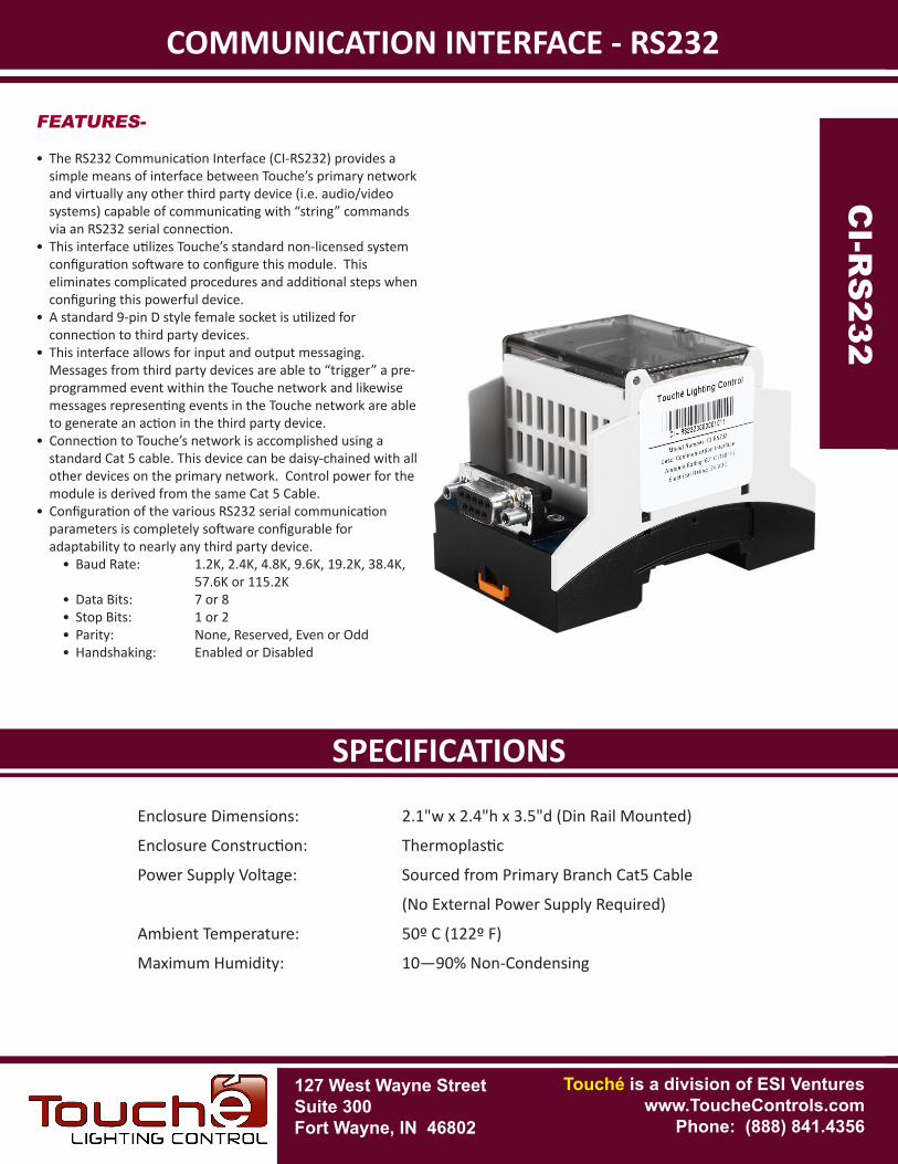
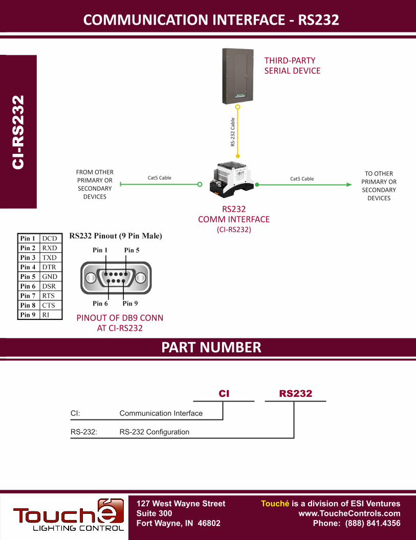
COMMUNICATION INTERFACE - RS232
Enclosure Dimensions: 2.1"w x 2.4"h x 3.5"d (Din Rail Mounted)
Enclosure Construction: Thermoplastic
Power Supply Voltage: Sourced from Primary Branch Cat5 Cable
(No External Power Supply Required)
Ambient Temperature: 50º C (122º F)
Maximum Humidity: 10—90% Non-Condensing
FEATURES-
• The RS232 Communication Interface (CI-RS232) provides a simple means of interface between Touche’s primary network and virtually any other third party device (i.e. audio/video systems) capable of communicating with “string” commands via an RS232 serial connection.
• This interface utilizes Touche’s standard non-licensed system configuration software to configure this module. This eliminates complicated procedures and additional steps when configuring this powerful device.
• A standard 9-pin D style female socket is utilized for connection to third party devices.
• This interface allows for input and output messaging. Messages from third party devices are able to “trigger” a pre-programmed event within the Touche network and likewise messages representing events in the Touche network are able to generate an action in the third party device.
• Connection to Touche’s network is accomplished using a standard Cat 5 cable. This device can be daisy-chained with all other devices on the primary network. Control power for the module is derived from the same Cat 5 Cable.
• Configuration of the various RS232 serial communication parameters is completely software configurable for adaptability to nearly any third party device.
• Baud Rate: 1.2K, 2.4K, 4.8K, 9.6K, 19.2K, 38.4K, 57.6K or 115.2K
• Data Bits: 7 or 8• Stop Bits: 1 or 2• Parity: None, Reserved, Even or Odd• Handshaking: Enabled or Disabled
CI-R
S232
CI-
RS
232
PART NUMBERSPECIFICATIONS
CI-R
S232
COMMUNICATION INTERFACE - RS232
CI: Communication Interface
CI RS232
RS-232: RS-232Configuration
RS232COMM INTERFACE
(CI-RS232)
CI-
RS
232
RS-2
32 C
able
THIRD-PARTY SERIAL DEVICE
SM
AO
S
TO OTHERPRIMARY OR SECONDARY
DEVICES
Cat5 CableCat5 CableFROM OTHERPRIMARY OR SECONDARY
DEVICES
PINOUT OF DB9 CONNAT CI-RS232
127 West Wayne StreetSuite 300Fort Wayne, IN 46802
Touché is a division of ESI Ventureswww.ToucheControls.com
Phone: (888) 841.4356
127 West Wayne StreetSuite 300Fort Wayne, IN 46802
SPECIFICATIONS
Touché is a division of ESI Ventureswww.ToucheControls.com
Phone: (888) 841.4356
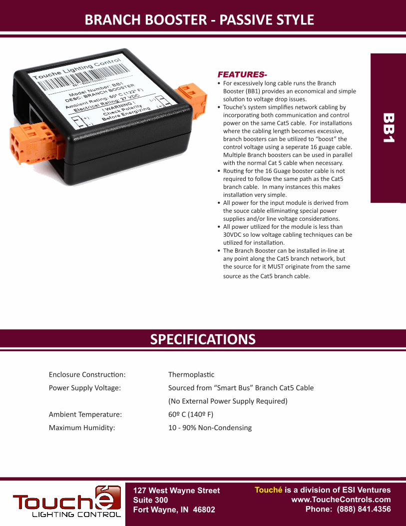
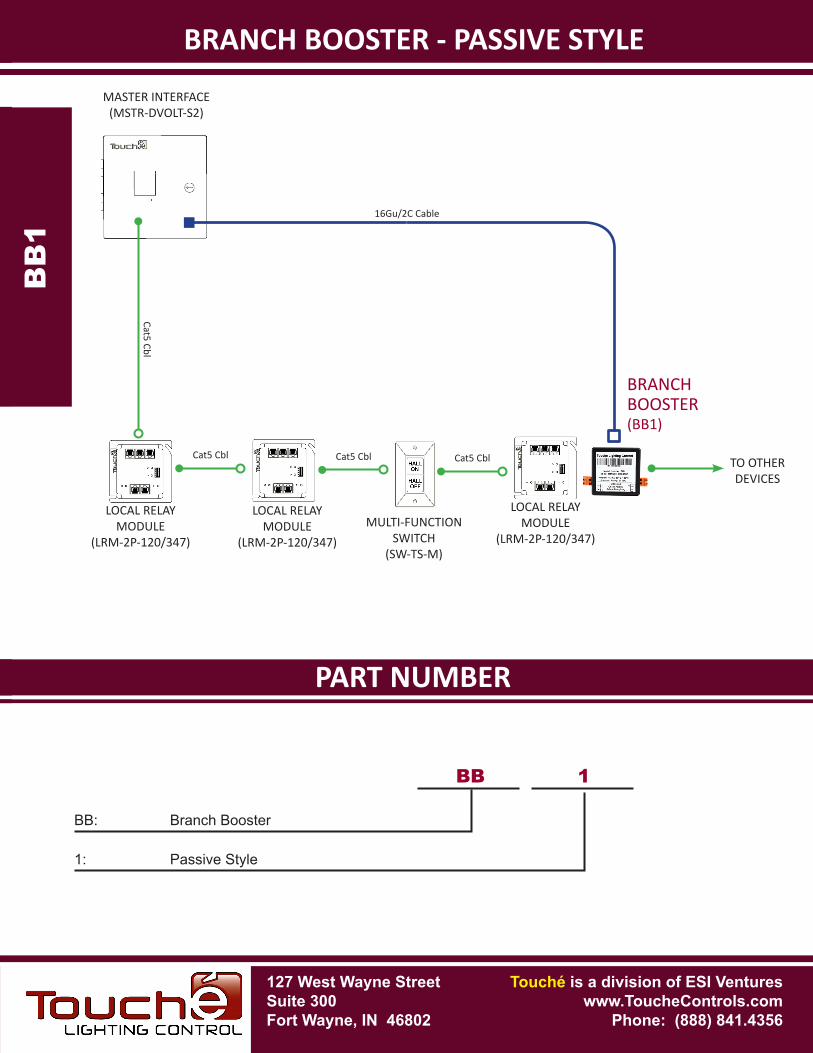
BRANCH BOOSTER - PASSIVE STYLE
FEATURES-• For excessively long cable runs the Branch
Booster (BB1) provides an economical and simple solution to voltage drop issues.
• Touche’s system simplifies network cabling by incorporating both communication and control power on the same Cat5 cable. For installations where the cabling length becomes excessive, branch boosters can be utilized to “boost” the control voltage using a seperate 16 guage cable. Multiple Branch boosters can be used in parallel with the normal Cat 5 cable when necessary.
• Routing for the 16 Guage booster cable is not required to follow the same path as the Cat5 branch cable. In many instances this makes installation very simple.
• All power for the input module is derived from the souce cable elliminating special power supplies and/or line voltage considerations.
• All power utilized for the module is less than 30VDC so low voltage cabling techniques can be utilized for installation.
• The Branch Booster can be installed in-line at any point along the Cat5 branch network, but the source for it MUST originate from the same source as the Cat5 branch cable.
Enclosure Construction: Thermoplastic
Power Supply Voltage: Sourced from “Smart Bus” Branch Cat5 Cable
(No External Power Supply Required)
Ambient Temperature: 60º C (140º F)
Maximum Humidity: 10 - 90% Non-CondensingB
B1B
B1
PART NUMBERSPECIFICATIONS
BRANCH BOOSTER - PASSIVE STYLEB
B1B
B1
BB: Branch Booster
BB
1: Passive Style
1
MASTER INTERFACE(MSTR-DVOLT-S2)
MULTI-FUNCTIONSWITCH
(SW-TS-M)
LOCAL RELAYMODULE
(LRM-2P-120/347)
TO OTHERDEVICES
LOCAL RELAYMODULE
(LRM-2P-120/347)
16Gu/2C Cable
Cat5 Cbl
LOCAL RELAYMODULE
(LRM-2P-120/347)
Cat5 Cbl Cat5 Cbl
Cat5 Cbl
BRANCHBOOSTER(BB1)
127 West Wayne StreetSuite 300Fort Wayne, IN 46802
Touché is a division of ESI Ventureswww.ToucheControls.com
Phone: (888) 841.4356
127 West Wayne StreetSuite 300Fort Wayne, IN 46802
SPECIFICATIONS
Touché is a division of ESI Ventureswww.ToucheControls.com
Phone: (888) 841.4356
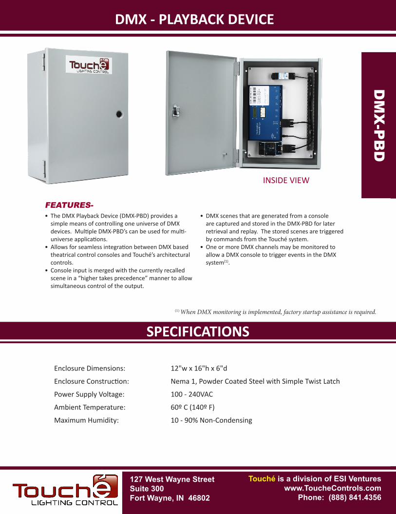
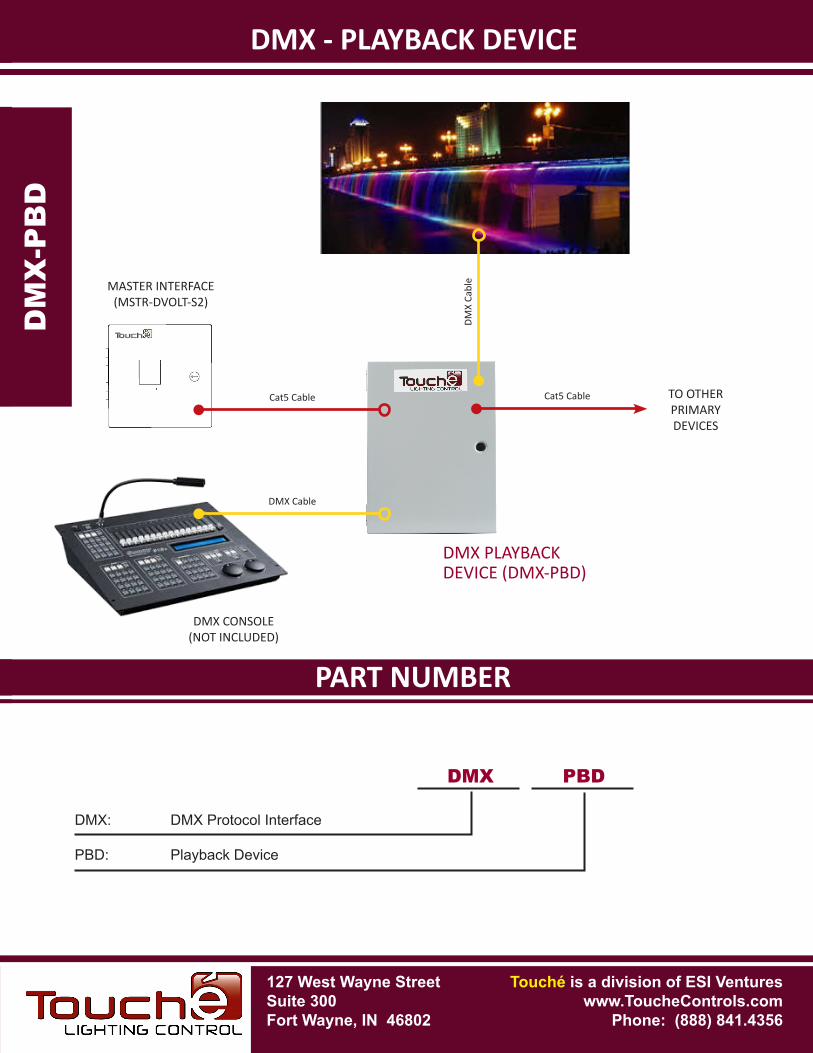
DMX - PLAYBACK DEVICE
• The DMX Playback Device (DMX-PBD) provides a simple means of controlling one universe of DMX devices. Multiple DMX-PBD’s can be used for multi-universe applications.
• Allows for seamless integration between DMX based theatrical control consoles and Touché’s architectural controls.
• Console input is merged with the currently recalled scene in a “higher takes precedence” manner to allow simultaneous control of the output.
• DMX scenes that are generated from a console are captured and stored in the DMX-PBD for later retrieval and replay. The stored scenes are triggered by commands from the Touché system.
• One or more DMX channels may be monitored to allow a DMX console to trigger events in the DMX system(1).
DM
X-P
BD
DM
X-P
BD
Enclosure Dimensions: 12"w x 16"h x 6"d
Enclosure Construction: Nema 1, Powder Coated Steel with Simple Twist Latch
Power Supply Voltage: 100 - 240VAC
Ambient Temperature: 60º C (140º F)
Maximum Humidity: 10 - 90% Non-Condensing
FEATURES-
(1) When DMX monitoring is implemented, factory startup assistance is required.
INSIDE VIEW
PART NUMBERSPECIFICATIONS
DMX - PLAYBACK DEVICED
MX
-PB
D
DM
X-P
BD
DMX
PBD: Playback Device
PBD
MASTER INTERFACE(MSTR-DVOLT-S2)
DMX PLAYBACKDEVICE (DMX-PBD)
DMX: DMX Protocol Interface
DMX CONSOLE(NOT INCLUDED)
127 West Wayne StreetSuite 300Fort Wayne, IN 46802
Touché is a division of ESI Ventureswww.ToucheControls.com
Phone: (888) 841.4356
Cat5 Cable TO OTHERPRIMARYDEVICES
Cat5 Cable
DMX Cable
DMX
Cabl
e
127 West Wayne StreetSuite 300Fort Wayne, IN 46802
SPECIFICATIONS
Touché is a division of ESI Ventureswww.ToucheControls.com
Phone: (888) 841.4356
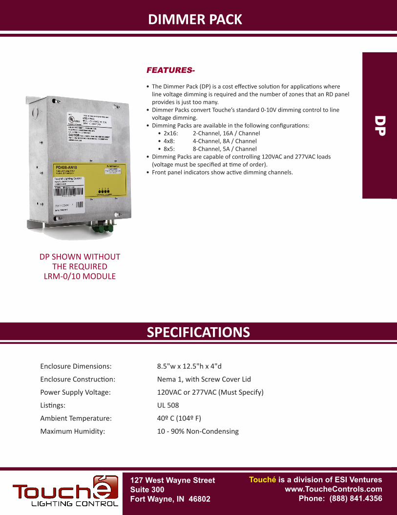
DIMMER PACK
DP
DP
Enclosure Dimensions: 8.5"w x 12.5"h x 4"d
Enclosure Construction: Nema 1, with Screw Cover Lid
Power Supply Voltage: 120VAC or 277VAC (Must Specify)
Listings: UL 508
Ambient Temperature: 40º C (104º F)
Maximum Humidity: 10 - 90% Non-Condensing
FEATURES-
• The Dimmer Pack (DP) is a cost effective solution for applications where line voltage dimming is required and the number of zones that an RD panel provides is just too many.
• Dimmer Packs convert Touche’s standard 0-10V dimming control to line voltage dimming.
• Dimming Packs are available in the following configurations:• 2x16: 2-Channel, 16A / Channel• 4x8: 4-Channel, 8A / Channel• 8x5: 8-Channel, 5A / Channel
• Dimming Packs are capable of controlling 120VAC and 277VAC loads (voltage must be specified at time of order).
• Front panel indicators show active dimming channels.
DP SHOWN WITHOUTTHE REQUIRED
LRM-0/10 MODULE
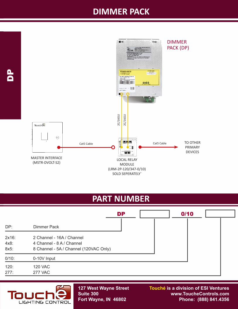
PART NUMBERSPECIFICATIONS
DIMMER PACKD
P
DP
DP
2x16: 2 Channel - 16A / Channel4x8: 4 Channel - 8 A / Channel8x5: 8 Channel - 5A / Channel (120VAC Only)
MASTER INTERFACE(MSTR-DVOLT-S2)
DIMMERPACK (DP)
DP: Dimmer Pack
2C/1
6GU
0/10
0/10: 0-10V Input
120: 120 VAC277: 277 VAC
LOCAL RELAYMODULE
(LRM-2P-120/347-0/10)SOLD SEPERATELY`
2C/1
6GU
127 West Wayne StreetSuite 300Fort Wayne, IN 46802
Touché is a division of ESI Ventureswww.ToucheControls.com
Phone: (888) 841.4356
Cat5 Cable TO OTHERPRIMARYDEVICES
Cat5 Cable