Specification for Electric Process Heaters
33
SPECIFICATION S-723 December 2020 Specification for Electric Process Heaters
Transcript of Specification for Electric Process Heaters

SPECIFICATION
S-723
December
2020
Specification for Electric Process Heaters

Revision history
VERSION DATE PURPOSE
1.0 December 2020 Issued for Use
Acknowledgements
This IOGP Specification was prepared by a Joint Industry Programme 33 Standardization of Equipment Specifications for Procurement organized by IOGP with support by the World Economic Forum (WEF).
Disclaimer
Whilst every effort has been made to ensure the accuracy of the information contained in this publication, neither IOGP nor any of its Members past present or future warrants its accuracy or will, regardless of its or their negligence, assume liability for any foreseeable or unforeseeable use made thereof, which liability is hereby excluded. Consequently, such use is at the recipient's own risk on the basis that any use by the recipient constitutes agreement to the terms of this disclaimer. The recipient is obliged to inform any subsequent recipient of such terms. This publication is made available for information purposes and solely for the private use of the user. IOGP will not directly or indirectly endorse, approve or accredit the content of any course, event or otherwise where this publication will be reproduced.
Copyright notice
The contents of these pages are © International Association of Oil & Gas Producers. Permission is given to reproduce this report in whole or in part provided (i) that the copyright of IOGP and (ii) the sources are acknowledged. All other rights are reserved. Any other use requires the prior written permission of IOGP.
These Terms and Conditions shall be governed by and construed in accordance with the laws of England and Wales. Disputes arising here from shall be exclusively subject to the jurisdiction of the courts of England and Wales.

Specification for Electric Process Heaters
Page 1 of 30 S-723 December 2020
Foreword
This specification was prepared under Joint Industry Programme 33 (JIP33) "Standardization of Equipment Specifications for Procurement" organized by the International Oil & Gas Producers Association (IOGP) with the support from the World Economic Forum (WEF). Companies from the IOGP membership participated in developing this specification to leverage and improve industry level standardization globally in the oil and gas sector. The work has developed a minimized set of supplementary requirements for procurement, with life cycle cost in mind, resulting in a common and jointly agreed specification, building on recognized industry and international standards.
Recent trends in oil and gas projects have demonstrated substantial budget and schedule overruns. The Oil and Gas Community within the World Economic Forum (WEF) has implemented a Capital Project Complexity (CPC) initiative which seeks to drive a structural reduction in upstream project costs with a focus on industry-wide, non-competitive collaboration and standardization. The CPC vision is to standardize specifications for global procurement for equipment and packages. JIP33 provides the oil and gas sector with the opportunity to move from internally to externally focused standardization initiatives and provide step change benefits in the sector's capital projects performance.
This specification has been developed in consultation with a broad user and supplier base to realize benefits from standardization and achieve significant project and schedule cost reductions.
The JIP33 work groups performed their activities in accordance with IOGP's Competition Law Guidelines (November 2014).

Specification for Electric Process Heaters
Page 2 of 30 S-723 December 2020
Table of Contents
Foreword .................................................................................................................................................. 1
Introduction ............................................................................................................................................... 4
1 Scope ....................................................................................................................................................... 6
1.1 General ........................................................................................................................................... 6
1.2 Inclusions ....................................................................................................................................... 6
1.3 Exclusions ...................................................................................................................................... 6
1.4 Extended use of this specification .................................................................................................. 6
1.5 Applicability .................................................................................................................................... 7
2 Normative references ............................................................................................................................... 7
3 Terms and definitions ............................................................................................................................... 9
4 General requirements ............................................................................................................................. 11
4.1 Basis for design ............................................................................................................................ 11
4.2 Hazardous area classification ...................................................................................................... 13
4.3 Environmental conditions ............................................................................................................. 13
5 Heater bundle ......................................................................................................................................... 13
5.1 Heater element and tubesheet ..................................................................................................... 13
5.2 Baffle support and bundle supports ............................................................................................. 15
5.3 Overtemperature protection ......................................................................................................... 15
5.4 Terminal boxes (general) ............................................................................................................. 15
5.5 MV/HV terminal boxes ................................................................................................................. 17
5.6 Lifting and lifting attachments....................................................................................................... 17
6 Pressure vessels .................................................................................................................................... 17
7 Power and control assembly .................................................................................................................. 18
7.1 Construction ................................................................................................................................. 18
7.2 Arc resistance............................................................................................................................... 19
7.3 Cooling ......................................................................................................................................... 19
7.4 Earthing ........................................................................................................................................ 20
7.5 Space heater ................................................................................................................................ 20
7.6 Incoming isolation device ............................................................................................................. 20
7.7 Power switching devices .............................................................................................................. 21
7.8 Semiconductor controlled process heaters .................................................................................. 21
7.9 Protection ..................................................................................................................................... 22
7.10 Control and measurement wiring ................................................................................................. 22
7.11 Control circuits.............................................................................................................................. 22
7.12 Current transformers .................................................................................................................... 22
7.13 Voltage transformers .................................................................................................................... 23
7.14 Cable entries ................................................................................................................................ 23

Specification for Electric Process Heaters
Page 3 of 30 S-723 December 2020
7.15 Electromagnetic compatibility ....................................................................................................... 23
7.16 Harmonics .................................................................................................................................... 23
7.17 Noise ............................................................................................................................................ 24
8 Measurement, protection and control ..................................................................................................... 24
8.1 General ......................................................................................................................................... 24
8.2 Protection and alarms .................................................................................................................. 24
8.3 Status indication and measurement ............................................................................................. 25
9 Inspection and testing ............................................................................................................................ 26
9.1 Heater element ............................................................................................................................. 26
9.2 Heater bundle ............................................................................................................................... 26
9.3 Power and control assembly ........................................................................................................ 27
10 Preparation for shipment ........................................................................................................................ 27
10.1 Cable entry holes ......................................................................................................................... 27
11 Identification and labelling ...................................................................................................................... 28
11.1 General ......................................................................................................................................... 28
11.2 Power and control assembly ........................................................................................................ 28
11.3 Process heater main terminal box................................................................................................ 29
Bibliography ............................................................................................................................................ 30
Specification for Electric Process Heaters
Page 4 of 30 S-723 December 2020
Introduction
The purpose of this specification is to define a minimum common set of requirements for the procurement of electric process heaters for application in the petroleum and natural gas industries.
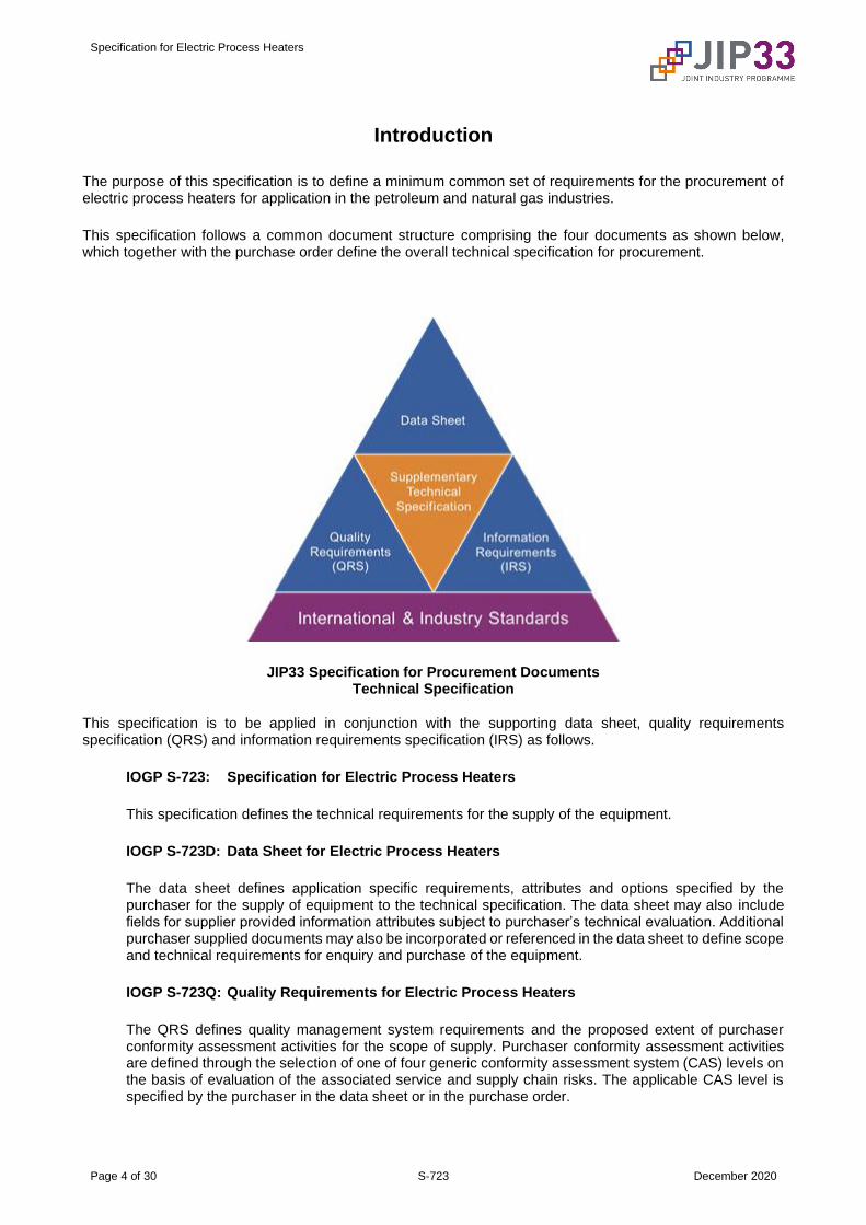
This specification follows a common document structure comprising the four documents as shown below, which together with the purchase order define the overall technical specification for procurement.
JIP33 Specification for Procurement Documents Technical Specification
This specification is to be applied in conjunction with the supporting data sheet, quality requirements specification (QRS) and information requirements specification (IRS) as follows.
IOGP S-723: Specification for Electric Process Heaters
This specification defines the technical requirements for the supply of the equipment.
IOGP S-723D: Data Sheet for Electric Process Heaters
The data sheet defines application specific requirements, attributes and options specified by the purchaser for the supply of equipment to the technical specification. The data sheet may also include fields for supplier provided information attributes subject to purchaser’s technical evaluation. Additional purchaser supplied documents may also be incorporated or referenced in the data sheet to define scope and technical requirements for enquiry and purchase of the equipment.
IOGP S-723Q: Quality Requirements for Electric Process Heaters
The QRS defines quality management system requirements and the proposed extent of purchaser conformity assessment activities for the scope of supply. Purchaser conformity assessment activities are defined through the selection of one of four generic conformity assessment system (CAS) levels on the basis of evaluation of the associated service and supply chain risks. The applicable CAS level is specified by the purchaser in the data sheet or in the purchase order.

Specification for Electric Process Heaters
Page 5 of 30 S-723 December 2020
IOGP S-723L: Information Requirements for Electric Process Heaters
The IRS defines the information requirements, including contents, format, timing and purpose to be provided by the supplier. It may also define specific conditions which invoke information requirements.
The terminology used within this specification and the supporting data sheet, QRS and IRS is in accordance with ISO/IEC Directives, Part 2.
The data sheet and IRS are published as editable documents for the purchaser to specify application specific requirements. The specification and QRS are fixed documents.
The order of precedence (highest authority listed first) of the documents shall be:
a) regulatory requirements;
b) contract documentation (e.g. purchase order);
c) purchaser defined requirements (data sheet, QRS, IRS);
d) this specification.
Specification for Electric Process Heaters
Page 6 of 30 S-723 December 2020
1 Scope
1.1 General
This specification covers requirements for the design, materials, construction, inspection, testing and preparation for shipment of electric process heater bundle assemblies, the associated pressure vessel, and power and control assemblies.
1.2 Inclusions
Requirements for the following are included in this specification:
— resistance-type, sheathed, immersion heater elements;
— electric process heaters fed from a three-phase supply up to 7.2 kV rated voltage;
— electrical components supplied in accordance with IEC and North American standards;
— single-tier, multi-tier and stacked electric process heaters;
— single-ended and double-ended electric process heaters.
1.3 Exclusions
Requirements for the following are excluded from this specification:
— heaters fed from a single-phase supply;
— direct air heaters for heating, ventilation and air conditioning;
— drum heaters;
— power and control assemblies installed outdoors or in a hazardous area;
— subsea flow line heating systems;
— pressure vessel accessories (e.g. valves, instrumentation);
— interface power and control cables;
— installation;
— power transformers.
1.4 Extended use of this specification
This specification may be used as a basis for the purchase of electric process heater systems that are outside the immediate scope of this specification, with those clauses that remain relevant for systems of a similar construction method, such as:
— liquid cooled power and control assembly components;
— systems with an outdoor power and control assembly.

Specification for Electric Process Heaters
Page 7 of 30 S-723 December 2020
1.5 Applicability
Requirements for power and control assemblies and pressure vessels are applicable only when these components are included in the scope of supply.
2 Normative references
The following documents are referred to in the text in such a way that some or all of their content constitutes requirements of this specification and the data sheet. For dated references, only the edition cited applies. For undated references, the latest edition of the references document (including any amendments) applies.
47 CFR 15, Code of Federal Regulations—Title 47: Telecommunication—Part 15: concerning unlicensed broadcasts and spurious emissions
ASME B1.20.1, Pipe Threads, General Purpose (Inch)
ASTM E230/E230M, Standard Specification for Temperature-Electromotive Force (emf) Tables for Standardized Thermocouples
ASTM E1137/E1137M, Standard Specification for Industrial Platinum Resistance Thermometers
CSA C22.1:2020, Canadian Electrical Code, Part I Safety Standard for Electrical Installations
CSA C22.2 No 253-16, Medium-voltage ac contactors, controllers, and control centres (Tri-national standard with UL 347 and NMX-J-564/106-ANCE)
IEC 60073, Basic and safety principles for man-machine interface, marking and identification – Coding principles for indicators and actuators
IEC 60079 (all parts), Explosive atmospheres
IEC 60146-1-1, Semiconductor converters – General requirements and line commutated converters – Part 1-1: Specification of basic requirements
IEC 60269-1, Low-voltage fuses – Part 1: General requirements
IEC 60269-4, Low-voltage fuses – Part 4: Supplementary requirements for fuse-links for the protection of semiconductor devices
IEC 60282-1, High-voltage fuses – Part 1: Current-limiting fuses
IEC 60423:2007, Conduit systems for cable management – Outside diameters of conduits for electrical installations and threads for conduits and fittings
IEC 60445, Basic and safety principles for man-machine interface, marking and identification – Identification of equipment terminals, conductor terminations and conductors
IEC 60529, Degrees of protection provided by enclosures (IP Code)
IEC 60584-1, Thermocouples – Part 1: EMF specifications and tolerances
IEC 60751, Industrial platinum resistance thermometers and platinum temperature sensors
IEC 60947-1, Low-voltage switchgear and controlgear – Part 1: General rules
IEC 60947-2, Low-voltage switchgear and controlgear – Part 2: Circuit-breakers

Specification for Electric Process Heaters
Page 8 of 30 S-723 December 2020
IEC 60947-3, Low-voltage switchgear and controlgear – Part 3: Switches, disconnectors, switch-disconnectors and fuse-combination units
IEC 61000-2-4:2002, Electromagnetic compatibility (EMC) – Part 2-4: – Compatibility levels in industrial for low-frequency conducted disturbances
IEC 61000-6-2, Electromagnetic compatibility (EMC) – Part 6-2: Generic standards – Immunity standard for industrial environments
IEC 61000-6-4, Electromagnetic compatibility (EMC) – Part 6-4: Generic standards – Emission standard for industrial environments
IEC 61243-5, Live working – Voltage detectors – Part 5: Voltage detecting systems (VDS)
IEC 61439-1, Low-voltage switchgear and controlgear assemblies – Part 1: General rules
IEC 61850 (all parts), Communication networks and systems for power utility automation
IEC 61869-2, Instrument transformers – Part 2: Additional requirements for current transformers
IEC 61869-3, Instrument transformers – Part 3: Additional requirements for inductive voltage transformers
IEC 61869-5, Instrument transformers – Part 5: Additional requirements for capacitor voltage transformers
IEC 62271-100, High-voltage switchgear and controlgear – Part 100: Alternating-current circuit-breakers
IEC 62271-103, High-voltage switchgear and controlgear – Part 103: Switches for rated voltages above 1 kV up to and including 52 kV
IEC 62271-106, High-voltage switchgear and controlgear – Part 106: Alternating current contactors, contactor-based controllers and motor-starters
IEC 62271-200:2011, High-voltage switchgear and controlgear – Part 200: AC metal-enclosed switchgear and controlgear for rated voltages above 1 kV and up to and including 52 kV
IEC 62271-206, High-voltage switchgear and controlgear – Part 206: Voltage presence indicating systems for rated voltages above 1 kV and up to and including 52 kV
IEC TR 61641:2014, Enclosed low-voltage switchgear and controlgear assemblies – Guide for testing under conditions of arcing due to internal fault
IEEE 519:2014, IEEE Recommended Practice and Requirements for Harmonic Control in Electric Power Systems
IEEE C37.20.7, IEEE Guide for Testing Switchgear Rated Up to 52 kV for Internal Arcing Faults
IOGP S-619, Specification for Unfired, Fusion Welded Pressure Vessels
ISO 3746, Acoustics — Determination of sound power levels and sound energy levels of noise sources using sound pressure — Survey method using an enveloping measurement surface over a reflecting plane
ISO 12944-1, Paints and varnishes — Corrosion protection of steel structures by protective paint systems — Part 1: General introduction
ISO 12944-2, Paints and varnishes — Corrosion protection of steel structures by protective paint systems — Part 2: Classification of environments

Specification for Electric Process Heaters
Page 9 of 30 S-723 December 2020
NACE MR0103/ISO 17945, Petroleum, petrochemical and natural gas industries — Metallic materials resistant to sulfide stress cracking in corrosive petroleum refining environments
NACE MR0175/ISO 15156, Petroleum and natural gas industries — Materials for use in H2S-containing environments in oil and gas production — Part 2: Cracking-resistant carbon and low-alloy steels, and the use of cast irons
NEMA 250, Enclosures for Electrical Equipment (1000 Volts Maximum)
NFPA 70:2020, National Electrical Code
TEMA, Standards of the Tubular Exchanger Manufacturers Association
UL 248-13, Standard for Safety – Low-Voltage Fuses – Part 13: Semiconductor Fuses
UL 347, Standard for Safety – Medium-Voltage AC Contactors, Controllers, and Control Centers
UL 347C, Standard for Safety – Outline of Investigation for Medium Voltage Solid State Resistive Load Controllers, Up to 15KV
UL 508A, Standard for Safety – Industrial Control Panels
UL 1030, Standard for Safety – Sheathed Heating Elements
3 Terms and definitions
For the purpose of this document, the following terms and definitions apply.
3.1 arc resistant arc contained equipment for which prescribed criteria are met in the event of an internal arc as demonstrated by type tests
3.2 earth ground make an electric connection between a given point in a system or in an installation or in equipment and a local earth
Note.- The connection to local earth may be – intentional, or – unintentional or accidental and may be permanent or temporary.
[SOURCE: IEC 60050-195:1998, 195-01-08, modified - "verb" and "verb, US" deleted from the terms]
3.3 hazardous area potentially explosive atmosphere area in which an explosive atmosphere is present or can be expected to be present, in quantities such that special precautions for the construction, installation and use of equipment are required
Note 1 to entry: IEC 60079-10-1, Explosive atmospheres – Part 10-1: Classification of areas – Explosive gas atmospheres, gives a classification of hazardous areas containing explosive gas atmospheres (see IEV 426-03-03, IEV 426-03-04 and IEV 426-03-05).

Specification for Electric Process Heaters
Page 10 of 30 S-723 December 2020
Note 2 to entry: IEC 60079-10-2, Explosive atmospheres – Part 10-2: Classification of areas – Explosive dust atmospheres, gives a classification of hazardous areas containing explosive dust atmospheres (see IEV 426-03-23, IEV 426-03-24, and IEV 426-03-25).
[SOURCE: IEC 60050-426:2020, 426-03-01, modified - admitted term has been added]
3.4 heater bundle assembly of heater elements, tubesheet and terminal boxes to be installed or removed as a single entity at the vessel
3.5 heater stage independently controlled group of heater elements connected in series or parallel and associated power and control components
3.6 high voltage HV voltage exceeding 1 kV
Note 1 to entry: Applicable to applications outside North America.
3.7 low voltage LV voltage up to and including 1 kV
3.8 medium voltage MV voltage between 1 kV and 35 kV
Note 1 to entry: Applicable to North American applications.
3.9 semiconductor switching device switching device designed to make and/or break the current in an electric circuit by means of the controlled conductivity of a semiconductor
[SOURCE: IEC 60050-441:2020, 441-14-03, modified – addition of “and/or break”]
3.10 type test conformity test made on one or more items representative of the production
[SOURCE: IEC 60050-151:2020, 151-16-16]
3.11 withdrawable heater element heater element which is removable from the tubesheet without the necessity of draining and depressurizing the vessel
3.12 bite coupling hydraulic fitting used for the mechanical fixing of a metal sheathed electric heater element to a tube sheet

Specification for Electric Process Heaters
Page 11 of 30 S-723 December 2020
3.13 notified body organization designated by a European Union country to assess the conformity of equipment for use in potentially explosive atmospheres before being placed on the market
Note 1 to entry: These bodies carry out tasks related to conformity assessment procedures set out in the applicable legislation, when a third party is required.
Note 2 to entry: The European Commission publishes a list of such notified bodies.
Note 3 to entry: Notified bodies can certify to European Directive 2014/34/EU.
3.14 certification body organization having successfully completed the IECEx assessment process and approved to operate within the IECEx Certified Equipment Scheme nationally recognized testing laboratory
3.15 nationally recognized test laboratory NRTL independent third-party organization recognized by the Occupational Safety and Health Administration (OSHA) to provide evaluation, testing and certification of products
3.16 accredited certification organization ACO organization accredited by the Standards Council of Canada to provide third party written assurance that a product, process, system or person conforms to specified requirements
3.17 rated output power value assigned by the manufacturer of the heater at rated voltage
4 General requirements
4.1 Basis for design
4.1.1
The process heater system rated output power shall be determined by the process conditions with the highest heat demand.
4.1.2
The heater stages shall be configured to operate across the range of process conditions.
4.1.3
The process heater shall be rated for continuous operation at rated output power.
NOTE Voltage tolerances should be considered when specifying rated output power.
4.1.4
When a heater stage is semiconductor controlled, the specified level of redundancy shall be applied to the semiconductor-controlled heater stage.

Specification for Electric Process Heaters
Page 12 of 30 S-723 December 2020
4.1.5
Individual system components and assemblies shall be in accordance with Table 1.
Table 1 – Component and assembly reference standards
Assembly Component IEC Standard North American Standard
General
Degree of ingress protection IEC 60529 NEMA 250 for enclosures
Terminal identification IEC 60445 NFPA 70 in the United States
CSA C22.1 in Canada
Heater bundle Elements N/A UL 1030
Temperature monitoring devices
RTDs IEC 60751 ASTM E1137/E1137M
Thermocouples IEC 60584-1 ASTM E230/E230M
Power and control assembly
LV fuses IEC 60269-1
UL 508A
addresses
complete assembly
LV switches IEC 60947-3
LV circuit breakers IEC 60947-2
LV contactors IEC 60947-1
MV/HV fuses IEC 60282-1 UL 347 or UL 347C addresses complete assembly in the United States
CSA C22.2 No 253-16 addresses complete assembly in Canada
MV/HV switches IEC 62271-103
HV/MV circuit breakers IEC 62271-100
MV/HV contactors IEC 62271-106
Current transformers IEC 61869-2
UL 508A or UL 347 or UL 347C
CSA C22.2 No 253-16
Voltage transformers IEC 61869-3
Capacitive transformers IEC 61869-3 or IEC 61869-5
4.1.6
When multiple heater stages are present within the same bundle, allocation of elements to stages shall maintain even heating throughout the bundle at the identified duty points.
4.1.7
The process heater shall be rated for continuous operation within the specified voltage tolerances.
4.1.8
Cooling fans in forced air-cooled power and control assemblies shall have a minimum design lifetime of five years.
4.1.9
Electronic components including capacitors shall have a minimum design lifetime of ten years.

Specification for Electric Process Heaters
Page 13 of 30 S-723 December 2020
4.2 Hazardous area classification
4.2.1
For applications outside North America, equipment rated for use in a hazardous area shall be in accordance with IEC 60079.
4.2.2
For applications outside North America, equipment rated for use in a hazardous area shall be supported with an equipment certificate issued by a notified body or certification body to the specified scheme.
4.2.3
For North American applications where the division scheme is applied, equipment rated for use in a hazardous area shall be in accordance with NFPA 70:2020, Article 500 or CSA C22.1:2020 CE Code, Annex J.
4.2.4
For North American applications where the zone scheme is applied, equipment rated for use in a hazardous area shall be in accordance with NFPA 70:2020, Article 505 or CSA C22.1:2020 CE Code, Section 18.
4.2.5
For North American applications, equipment rated for use in a hazardous area shall be NRTL or ACO certified for the specified environment.
4.2.6
For equipment rated for use in a hazardous area, an external surface temperature monitoring detector shall be provided on the tubesheet flange of the process heater.
4.3 Environmental conditions
The process heater and associated equipment shall be designed for the specified environmental conditions.
5 Heater bundle
5.1 Heater element and tubesheet
5.1.1
The method of sealing sheaths, for heater elements and temperature detectors, to tubesheets shall be seal welding, strength welding or bite couplings.
5.1.2
The weld procedure for strength welded type sheath-to-tubesheet joints shall be in accordance with the pressure vessel design code.
5.1.3
Heater element end terminals at the terminal box side shall be sealed to prevent moisture ingress.

Specification for Electric Process Heaters
Page 14 of 30 S-723 December 2020
5.1.4
Heater elements shall be constructed from 80/20 NiCr resistance wire surrounded by compacted magnesium oxide powder.
NOTE Alternate materials may be proposed, subject to a technology readiness assessment.
5.1.5
Spare withdrawable heater elements shall be supplied loose.
5.1.6
For non-withdrawable heater elements, a minimum of 10 % spare elements shall be installed.
NOTE Spare elements may be specified as operational from the outset.
5.1.7
Non-withdrawable spare elements shall be provided with conductors, terminals and fixings to connect to any heater stage, or to a dedicated heater stage if bus links are used.
5.1.8
Spare heater elements shall be identified and wired to a dedicated earth terminal inside the terminal box.
5.1.9
The internal temperature of the main terminal box shall not exceed 70 °C (158 °F).
NOTE An unheated length of element between the tubesheet and the terminal box may be provided to maintain the internal temperature of terminal box.
5.1.10
At least one earth stud shall be provided on the tubesheet.
5.1.11
The tubesheet and terminal box shall be connected by an earth conductor at the earth studs.
5.1.12
The heater element tubesheet shall be supplied in accordance with the specified pressure vessel design code.
5.1.13
Unheated element lengths shall be provided where there is zero or restricted process fluid flow.
5.1.14
Bite couplings shall be certified by a third party to an industry standard.

Specification for Electric Process Heaters
Page 15 of 30 S-723 December 2020
5.2 Baffle support and bundle supports
5.2.1
Fixed bundle supports and guides inside the vessel or tank shall be located to prevent bending or damage during insertion and removal of the bundle.
5.2.2
Baffle supports shall be spaced to prevent bending and flow induced vibration at design and full operating range conditions including start-up and shutdown.
5.2.3
The baffle support material shall be the same as the element sheath material.
5.3 Overtemperature protection
5.3.1
At least two temperature detectors attached to separate heater elements shall be provided per heater bundle.
5.3.2
Temperature detectors shall be wired to a dedicated terminal box.
5.3.3
Temperature detectors on heater elements shall be located at the point of highest anticipated sheath temperature.
5.3.4
The method of sealing the temperature detector sheaths or thermowells to the tubesheet shall be the same as that of the heater element sheaths.
5.3.5
The heater element temperature detector sheath or thermowell material shall be the same as the heater element sheath material.
5.3.6
Temperature detectors shall be Type K thermocouple elements or PT 100 devices.
5.4 Terminal boxes (general)
5.4.1
For applications outside North America, terminal boxes shall have a minimum degree of ingress protection of IP55 in accordance with IEC 60529.
5.4.2
For North American applications, terminal boxes shall have a rating of NEMA 4X.

Specification for Electric Process Heaters
Page 16 of 30 S-723 December 2020
5.4.3
Neutral linking for star (wye) connected loads shall be implemented inside the terminal box.
5.4.4
For applications outside North America, threaded cable entries shall be a metric size in accordance with IEC 60423:2007, Table 2.
5.4.5
For North American applications, threaded cable entries shall be in accordance with ASME B1.20.1.
5.4.6
When single core line conductors have been specified, gland plates shall be of a non-magnetic material.
5.4.7
Earth terminals shall be provided inside and outside the terminal box.
5.4.8
The main terminal box shall be provided with a space heater.
5.4.9
The main terminal box space heater shall be controlled from the power and control assembly.
5.4.10
Labels warning that space heater terminals may be live when power and control circuits are isolated shall be fixed internally and externally to the main terminal box.
5.4.11
The main terminal box space heater shall be in operation when the process heater is de-energized.
5.4.12
Terminal box cable entries shall not be top entry.
5.4.13
Terminal boxes shall be made of grade 316 stainless steel or have a protective paint system in accordance with ISO 12944-1 and ISO 12944-2.
5.4.14
For onshore exterior applications, the protective paint system corrosivity category shall be a minimum of C3 in accordance with ISO 12944-2.

Specification for Electric Process Heaters
Page 17 of 30 S-723 December 2020
5.4.15
For offshore exterior applications, the protective paint system corrosivity category shall be CX in accordance with ISO 12944-2.
5.4.16
The protective paint system durability category shall be a minimum of “medium” in accordance with ISO 12944-1.
5.4.17
Terminal box covers weighing more than 25 kg (55 lb) shall be provided with hoisting attachments or be vertically hinged.
5.4.18
When process fluid breach detection is specified, a dedicated signal shall be hard-wired directly to de-energize the process heater.
5.5 MV/HV terminal boxes
5.5.1
Non-Ex eb and non-Ex ec terminal boxes shall be rated for the calculated pressure build-up resulting from a three-phase fault at the level and duration allowed by the circuit protection.
5.5.2
When a pressure relief device is used to relieve pressure build-up, the discharge shall be directed away from locations where personnel may be present.
5.6 Lifting and lifting attachments
5.6.1
Tubesheets shall be provided with lifting lugs, pulling lugs or eyebolts on the outer face.
5.6.2
Lifting lugs, pulling lugs and eyebolts on tubesheets shall support at least 150 % of the weight of the heater bundle assembly.
5.6.3
The material of the lifting lug attachments shall be of same nominal composition as that of tubesheet.
6 Pressure vessels
Pressure vessels shall be supplied in accordance with IOGP S-619.

Specification for Electric Process Heaters
Page 18 of 30 S-723 December 2020
7 Power and control assembly
7.1 Construction
7.1.1
For applications outside North America, the enclosure shall have a minimum degree of ingress protection of IP3X in accordance with IEC 60529.
7.1.2
For North American applications, the enclosure shall have a minimum rating of NEMA 1.
7.1.3
MV/HV electrical power components shall be segregated from LV components by a minimum degree of protection of IP3X in accordance with IEC 60529.
7.1.4
Compartments shall be accessible from the front of the assembly via padlockable or bolted hinged doors.
7.1.5
LV power compartment doors shall:
— be prevented from opening unless all components in the compartment are electrically dead and isolated; or
— require the use of a tool to open.
7.1.6
MV/HV power compartment doors shall be prevented from opening unless all components in the compartments are electrically dead and isolated.
7.1.7
LV power compartments segregated from control and measurement compartments shall be by a degree of protection of a minimum of IP2X in accordance with IEC 60529.
7.1.8
LV power compartments containing control or measurement components shall have a minimum degree of protection of IP2X in accordance with IEC 60529.
7.1.9
When a pressure relief device is used to relieve pressure build-up, the discharge shall be directed away from locations where personnel may be present.
7.1.10
Power and control assemblies shall be provided with lifting lugs or eyebolts on the outer face.

Specification for Electric Process Heaters
Page 19 of 30 S-723 December 2020
7.2 Arc resistance
7.2.1
Enclosures for MV/HV applications shall be arc resistant.
7.2.2
The rated arc fault current shall be at least the maximum prospective short-circuit current.
7.2.3
For MV/HV applications outside North America, the enclosure accessibility shall be "AFLR" in accordance with IEC 62271-200.
7.2.4
For MV/HV applications outside North America, conformance shall be demonstrated by type tests in accordance with IEC 62271-200:2011, AA.5.
7.2.5
For arc resistant North American applications, the enclosure accessibility shall be at least type 2B in accordance with IEEE C37.20.7.
7.2.6
For arc resistant North American applications, conformance shall be demonstrated by type tests in accordance with IEEE C37.20.7.
7.2.7
For LV arc resistant applications outside North America, conformance shall be demonstrated by arcing class A tests in accordance with IEC TR 61641:2014, Table A.1
7.3 Cooling
7.3.1
Cooling fan redundancy shall be provided on an N+1 basis for forced air-cooled power and control assemblies.
7.3.2
Loss of availability of any cooling fan shall initiate an alarm.
7.3.3
Each cooling fan shall have a dedicated circuit protection device.
7.3.4
Cooling fans shall have grease-lubricated anti-friction bearings, packed and sealed for life.

Specification for Electric Process Heaters
Page 20 of 30 S-723 December 2020
7.3.5
Cooling fan filters shall be maintainable from outside the cabinet while the process heater is in operation.
7.4 Earthing
7.4.1
A copper earth busbar at least 25 mm x 5 mm (1 in x 0,2 in) extending the length of the enclosure shall be provided.
7.4.2
The earth busbar shall be rated for the specified maximum prospective short-circuit current.
7.4.3
Earthing conductors connected to the main earth busbar shall be terminated individually at designated terminals.
7.4.4
Power and control assemblies shall have at least one M10 (3/8 in) external earth point.
7.4.5
Metallic non-current carrying parts of the power and control assembly shall be bonded together and connected to the internal earth busbar.
7.4.6
Hinge-mounted conductive panels incorporating mounted electrical components shall be provided with supplemental equipotential bonding.
7.5 Space heater
7.5.1
The power and control assembly space heater shall be operational when the power and control assembly is de-energized.
7.5.2
The power and control assembly space heater shall be thermostatically or hygrostatically controlled.
7.5.3
When a power and control assembly space heater is provided, labels warning that space heater terminals may be live when power and control circuits are isolated shall be fixed internally and externally to the power and control assembly.
7.6 Incoming isolation device
7.6.1
The incoming isolation device shall be a fault-make load-break switch or a circuit breaker.

Specification for Electric Process Heaters
Page 21 of 30 S-723 December 2020
7.6.2
When the incoming power supply includes a neutral conductor, the incoming isolation device shall isolate four poles.
7.7 Power switching devices
7.7.1
For applications outside North America, the utilization category for LV switches shall be at least AC 21B in accordance with IEC 60947-3.
7.7.2
For North American applications, LV switches shall be load break.
7.7.3
Each stage of a multi-stage heater shall have a means for independent isolation.
7.7.4
Switch-disconnectors and circuit breakers shall be provided with facilities for padlocking in the "off" position.
7.8 Semiconductor controlled process heaters
7.8.1
The process heater control system shall prevent contactor chattering by provision of a hysteresis control facility with adjustable bandwidth.
7.8.2
For 4-wire star (wye) systems, all three phases shall be switched.
7.8.3
When semiconductor switching devices are operated in parallel, the current shall be balanced.
7.8.4
For applications outside North America, LV process heater semiconductor switching device over-current protection shall be provided by ultra-rapid fuses in accordance with IEC 60269-4.
7.8.5
For North American applications, LV process heater semiconductor switching device over-current protection shall be provided by ultra-rapid fuses in accordance with UL 248-13.
7.8.6
Drivers of semiconductor switching devices shall control the power output of the heater stage in no greater than 1 % increments.

Specification for Electric Process Heaters
Page 22 of 30 S-723 December 2020
7.8.7
The output power shall be a linear function of the input control signal.
7.9 Protection
7.9.1
Operation of a main circuit fuse shall result in de-energization of all three phases.
7.9.2
Space heaters for the main terminal box and the power and control assembly shall be protected by miniature circuit breakers.
7.10 Control and measurement wiring
7.10.1
Wiring shall be provided with wire markers at both ends in accordance with the identification used on the manufacturer's drawings.
7.10.2
Terminals shall incorporate pressure plates to prevent screws and nuts bearing directly onto wires.
7.10.3
Terminations shall be made using a proprietary crimping system.
7.11 Control circuits
7.11.1
Each overtemperature trip device shall have a dedicated signal hard-wired directly to de-energize the process heater.
7.11.2
Terminals for different voltages shall be segregated.
7.11.3
When spare heater stages are specified, the control system shall have provision to transfer stages between "standby" and "duty".
7.12 Current transformers
7.12.1
Current transformer secondary neutral points shall be earthed via a disconnecting link.

Specification for Electric Process Heaters
Page 23 of 30 S-723 December 2020
7.12.2
Current transformer wiring connected to external circuits shall have shorting links located at the outgoing terminals.
7.13 Voltage transformers
7.13.1
Voltage transformer secondary neutral points shall be earthed via a disconnecting link.
7.13.2
MV/HV power and control assemblies shall have provision for testing the incoming supply conductors to prove absence of voltage without removal of fixed barriers or guards.
7.14 Cable entries
When single core line conductors have been specified, gland plates shall be of a non-magnetic material.
7.15 Electromagnetic compatibility
7.15.1
For applications outside North America, the power and control assembly shall be in accordance with the generic emission requirements for the industrial environment defined in IEC 61000-6-4.
7.15.2
For North American applications, the power and control assembly shall be accordance with the Class A emission requirements of 47 CFR 15.
7.15.3
The power and control assembly shall be in accordance with the generic immunity requirements for the industrial environment defined in IEC 61000-6-2.
7.16 Harmonics
7.16.1
The permissible harmonic current emission shall be calculated at the specified minimum prospective three-phase short-circuit current.
7.16.2
For harmonic current emissions, the power and control assembly shall be in accordance with the limits specified in IEEE 519:2014, Table 2.
7.16.3
For applications outside North America, the power and control assembly shall be immune to harmonics in the supply, below the limits specified by IEC 61000-2-4:2002, class 3.

Specification for Electric Process Heaters
Page 24 of 30 S-723 December 2020
7.16.4
For North American applications, the power and control assembly shall be immune to harmonics in the supply that are at a level below the limits specified in IEEE 519:2014, Table 1.
7.17 Noise
7.17.1 Noise limits
The sound pressure level measured at 1 m (3.28 ft) distance from the power and control assembly, at any position, shall not exceed 75 dB(A) at loads between zero and the rated output of the unit.
7.17.2
Noise levels shall be measured in accordance with ISO 3746.
8 Measurement, protection and control
8.1 General
8.1.1
Indicating instruments and operating devices shall be mounted on the front of the power and control assembly.
8.1.2
Manual control of the power output shall be provided at the front of the power and control assembly.
8.1.3
When a human machine interface unit failure occurs, the process heater and protection functions shall continue to operate.
8.1.4
Indications and alarms provided by a human machine interface unit shall be visible without a password.
8.1.5
Indicating instruments and operating devices shall be no more than 2 m (78 in) above floor level.
8.2 Protection and alarms
8.2.1
Each heater stage shall be provided with the following alarm and protection functions:
— earth fault trip as determined by the supply earthing configuration;
— semiconductor over-temperature trip if semiconductor control is used.
8.2.2
The process heater system shall be provided with the following protection and alarm functions:

Specification for Electric Process Heaters
Page 25 of 30 S-723 December 2020
— power and control assembly cooling fan out of service alarm if forced air-cooling is provided;
— power and control assembly overtemperature alarm if forced air-cooling is provided;
— heater element sheath overtemperature trip;
— heater tubesheet flange external surface overtemperature alarm;
— heater tubesheet flange external surface overtemperature trip.
8.2.3
Trip functions shall be locked out until manually reset.
8.2.4
When remote reset is not specified, manual reset shall be provided at the power and control assembly.
8.2.5
Heater bundles shall have the facility to be shut down on receipt of an external trip signal.
8.3 Status indication and measurement
8.3.1
The following information shall be provided on the front of the power and control assembly:
— status of on/off heater stages;
— percentage duty of semiconductor-controlled heater stages;
— ammeter displaying output root mean square current with phase selection for all phases;
— system power output;
— main terminal box space heater status;
— power and control assembly space heater status;
— status of protection and alarms listed in 9.2;
— external trip status;
— status of each temperature detector.
8.3.2
Remote indication of the following shall be provided:
— process heater on/off or percentage duty;
— process heater available;
— common alarm.
NOTE Indication per heater stage may be specified.

Specification for Electric Process Heaters
Page 26 of 30 S-723 December 2020
8.3.3
Indication lights shall be LEDs, displaying colours in accordance with IEC 60073.
8.3.4
The incoming isolation device and each heater stage contactor shall be provided with at least one spare normally-open potential-free auxiliary contact.
8.3.5
The incoming isolation device and each heater stage contactor shall be provided with at least one spare normally-closed potential-free auxiliary contact.
8.3.6
Spare potential-free auxiliary contacts shall be connected to terminals for external use.
9 Inspection and testing
9.1 Heater element
Electrical testing shall be carried out for heater elements in accordance with UL 1030.
NOTE This requirement only applies to testing criteria and does not stipulate full UL 1030 conformance.
9.2 Heater bundle
9.2.1
The following tests shall be performed on the heater bundle:
— heater bundle insulation resistance test;
— heater bundle dielectric withstand test;
— resistance test of each heater stage at ambient temperature;
— terminal box space heater insulation resistance test;
— function test of each temperature detector;
— HV/MV heater bundle partial discharge test.
9.2.2
Dielectric withstand testing for heater bundles with a voltage rating ≤ 250 V r.m.s shall be performed for one minute at a voltage of 1 000 V r.m.s at the supply frequency.
9.2.3
Dielectric withstand testing for heater bundles with a voltage rating > 250 V r.m.s shall be performed for one minute at a minimum voltage of 1 000 + 2Un V r.m.s at supply frequency where Un is the rated voltage.
Specification for Electric Process Heaters
Page 27 of 30 S-723 December 2020
9.2.4
The integrity of the sheath-to-tubesheet joint shall be tested by one of the following methods:
— a pneumatic test on the vessel side at a gauge pressure between 50 kPa (7.5 psi) and 100 kPa (15 psi), using a soap-water solution to identify leaks; or
— a hydrostatic test on the vessel side at a gauge pressure in accordance with the design code.
NOTE A pneumatic test should not replace a hydrostatic test when required by the design code.
9.3 Power and control assembly
9.3.1
LV power and control panel assemblies shall be tested in accordance with IEC 61439-1.
9.3.2
For applications outside North America, MV/HV power and control panel assemblies shall be tested in accordance with IEC 62271-200.
9.3.3
For North American applications, MV/HV power and control panel assemblies shall be tested in accordance with UL 347 or UL 347C.
9.3.4
Semiconductors shall be tested in accordance with IEC 60146-1-1.
9.3.5
For North American applications, LV power and control panel assemblies shall be listed or certified by an NRTL or ACO.
9.3.6
For North American applications, MV/HV power and control panel assemblies shall be certified as specified.
9.3.7
Temperature rise tests for forced air-cooled power and control assemblies shall be performed without operation of the cooling fan provided for redundancy.
10 Preparation for shipment
10.1 Cable entry holes
10.1.1
Threaded cable entries shall be fitted with blanking plugs to maintain the ingress protection rating during transportation and storage.

Specification for Electric Process Heaters
Page 28 of 30 S-723 December 2020
10.1.2
Non-threaded cable entry holes shall be sealed prior to shipment.
10.1.3
For equipment rated for use in a hazardous area, blanking plugs shall be certified.
10.2
Desiccant shall be provided in terminal boxes, with tubesheets and at both ends of the tube bundles.
10.3
Packaging shall be marked with a warning label stating that preservation measures have been applied and the period of validity.
11 Identification and labelling
11.1 General
11.1.1
Identification and label plates shall be made of 316 stainless steel.
11.1.2
Identification and label plates shall be attached to non-removable parts of the associated equipment with stainless steel 316 fixings.
11.1.3
Identification and label plates shall have the required information stamped or engraved.
11.2 Power and control assembly
The power and control assembly identification and label plate shall include the following:
— supplier's name;
— supplier's model number;
— supplier's serial number;
— year of manufacture;
— system voltage, phases, wires and frequency;
— IP rating or NEMA enclosure rating;
— maximum ambient air temperature, if other than 40 °C;
— altitude for which the assembly is designed, if exceeding 1 000 m above sea-level;
— rated fault current;
Specification for Electric Process Heaters
Page 29 of 30 S-723 December 2020
— rated input current;
— rated output power;
— weight;
— space heater voltage (if applicable);
— space heater rated current (if applicable).
11.3 Process heater main terminal box
The process heater main terminal box identification and label plate shall include the following:
— supplier's name;
— supplier's model number;
— supplier's serial number;
— year of manufacture;
— system voltage, phases and frequency;
— heater elements connection (star (wye) or delta);
— IP rating or NEMA enclosure rating;
— maximum ambient air temperature, if other than 40 °C;
— rated fault current;
— rated input current;
— rated output power;
— weight;
— space heater voltage;
— space heater rated current.
NOTE Space heater information may be provided on a separate space heater terminal box nameplate.

Specification for Electric Process Heaters
Page 30 of 30 S-723 December 2020
Bibliography
[1] IEC 60050-151:2020, International Electrotechnical Vocabulary – Part 151: Electrical and magnetic devices
[2] IEC 60050-195:1998, International Electrotechnical Vocabulary – Part 195: Earthing and protection against electric shock
[3] IEC 60050-426:2020, International Electrotechnical Vocabulary (IEV) – Part 426: Explosive atmospheres
[4] IEC 60050-441:2020, International Electrotechnical Vocabulary Chapter 441: Switchgear, controlgear and fuses