
SpecificationfortheOhmicHeatingModule … · SpecificationfortheOhmicHeatingModule...
49
Woodruff Scientific Inc. Specification for OH Bank Module March 11, 2016 Specification for the Ohmic Heating Module Capacitor Charge/Discharge Power Supply (CCDPS) for FLARE March 11, 2016 1
Transcript of SpecificationfortheOhmicHeatingModule … · SpecificationfortheOhmicHeatingModule...

Woodruff Scientific Inc. Specification for OH Bank Module March 11, 2016
Specification for the Ohmic Heating ModuleCapacitor Charge/Discharge Power Supply (CCDPS) for FLARE
March 11, 2016
1

Woodruff Scientific Inc. Specification for OH Bank Module March 11, 2016
Contents1 Specifications for Ohmic Heating (OH) bank module 4
1.1 Description . . . . . . . . . . . . . . . . . . . . . . . . . . . . . . . . . . . . . . . . . . . . . . 41.2 Full Assembly: module . . . . . . . . . . . . . . . . . . . . . . . . . . . . . . . . . . . . . . . . 61.3 Capacitors . . . . . . . . . . . . . . . . . . . . . . . . . . . . . . . . . . . . . . . . . . . . . . . 71.4 Forward Switch . . . . . . . . . . . . . . . . . . . . . . . . . . . . . . . . . . . . . . . . . . . . 71.5 Crowbar Switch . . . . . . . . . . . . . . . . . . . . . . . . . . . . . . . . . . . . . . . . . . . . 71.6 Buswork . . . . . . . . . . . . . . . . . . . . . . . . . . . . . . . . . . . . . . . . . . . . . . . . 81.7 Charging . . . . . . . . . . . . . . . . . . . . . . . . . . . . . . . . . . . . . . . . . . . . . . . 91.8 Dump . . . . . . . . . . . . . . . . . . . . . . . . . . . . . . . . . . . . . . . . . . . . . . . . . 91.9 Harnessing . . . . . . . . . . . . . . . . . . . . . . . . . . . . . . . . . . . . . . . . . . . . . . 91.10 Polarity switching . . . . . . . . . . . . . . . . . . . . . . . . . . . . . . . . . . . . . . . . . . 101.11 Diagnostics . . . . . . . . . . . . . . . . . . . . . . . . . . . . . . . . . . . . . . . . . . . . . . 101.12 Safety . . . . . . . . . . . . . . . . . . . . . . . . . . . . . . . . . . . . . . . . . . . . . . . . . 101.13 Cooling requirements . . . . . . . . . . . . . . . . . . . . . . . . . . . . . . . . . . . . . . . . . 101.14 Connections . . . . . . . . . . . . . . . . . . . . . . . . . . . . . . . . . . . . . . . . . . . . . . 111.15 Environmental requirements . . . . . . . . . . . . . . . . . . . . . . . . . . . . . . . . . . . . . 12
2 References 13
3 Appendices 133.1 Engineering Drawings and Vendor Specs . . . . . . . . . . . . . . . . . . . . . . . . . . . . . . 13
2

Woodruff Scientific Inc. Specification for OH Bank Module March 11, 2016
List of Tables1 Target parameters for OH bank . . . . . . . . . . . . . . . . . . . . . . . . . . . . . . . . . . . . . . . . 42 Bus Clamp Dimensions by Bank (inches) . . . . . . . . . . . . . . . . . . . . . . . . . . . . . . . . . . . 13
List of Figures1 Circuit Schematic . . . . . . . . . . . . . . . . . . . . . . . . . . . . . . . . . . . . . . . . . . . . . . . . 42 PSpice Schematic and Analysis . . . . . . . . . . . . . . . . . . . . . . . . . . . . . . . . . . . . . . . . 53 Engineering design point for bank module . . . . . . . . . . . . . . . . . . . . . . . . . . . . . . . . . . 64 Capacitor detail . . . . . . . . . . . . . . . . . . . . . . . . . . . . . . . . . . . . . . . . . . . . . . . . . 75 Switch detail, calling out components and references to drawing numbers . . . . . . . . . . . . . . . . 86 Buswork detail with labels for machining drawings. . . . . . . . . . . . . . . . . . . . . . . . . . . . . . 87 Charging switch and connection detail. . . . . . . . . . . . . . . . . . . . . . . . . . . . . . . . . . . . . 98 Dump detail with labels for major components. . . . . . . . . . . . . . . . . . . . . . . . . . . . . . . . 109 Connections to the bank. . . . . . . . . . . . . . . . . . . . . . . . . . . . . . . . . . . . . . . . . . . . 1110 Schematic for charge, dump and ground relay control. . . . . . . . . . . . . . . . . . . . . . . . . . . . 1211 OH Bleed Resistor Channel . . . . . . . . . . . . . . . . . . . . . . . . . . . . . . . . . . . . . . . . . . 1312 Ignitron Cage - Copper . . . . . . . . . . . . . . . . . . . . . . . . . . . . . . . . . . . . . . . . . . . . 1413 Ignitron Cage - Stainless . . . . . . . . . . . . . . . . . . . . . . . . . . . . . . . . . . . . . . . . . . . . 1514 OH Bus Upper . . . . . . . . . . . . . . . . . . . . . . . . . . . . . . . . . . . . . . . . . . . . . . . . . 1615 OH Bus Lower . . . . . . . . . . . . . . . . . . . . . . . . . . . . . . . . . . . . . . . . . . . . . . . . . 1716 OH Bus Insulation . . . . . . . . . . . . . . . . . . . . . . . . . . . . . . . . . . . . . . . . . . . . . . . 1817 OH Bus Vertical Support - 2 Off . . . . . . . . . . . . . . . . . . . . . . . . . . . . . . . . . . . . . . . 1918 OH Bus Vertical . . . . . . . . . . . . . . . . . . . . . . . . . . . . . . . . . . . . . . . . . . . . . . . . 2019 OH Bus Resistor . . . . . . . . . . . . . . . . . . . . . . . . . . . . . . . . . . . . . . . . . . . . . . . . 2120 OH Bus Clamps (see Table 2 for table of dimensions) . . . . . . . . . . . . . . . . . . . . . . . . . . . . 2221 OH Cable Header . . . . . . . . . . . . . . . . . . . . . . . . . . . . . . . . . . . . . . . . . . . . . . . . 2322 Outer Triax Connector . . . . . . . . . . . . . . . . . . . . . . . . . . . . . . . . . . . . . . . . . . . . . 2423 Inner Triax Connector . . . . . . . . . . . . . . . . . . . . . . . . . . . . . . . . . . . . . . . . . . . . . 2524 Dump Lid . . . . . . . . . . . . . . . . . . . . . . . . . . . . . . . . . . . . . . . . . . . . . . . . . . . . 2625 Dump Tank . . . . . . . . . . . . . . . . . . . . . . . . . . . . . . . . . . . . . . . . . . . . . . . . . . . 2726 Dump Stick Eyehook Bracket . . . . . . . . . . . . . . . . . . . . . . . . . . . . . . . . . . . . . . . . . 28
3
Woodruff Scientific Inc. Specification for OH Bank Module March 11, 2016
1 Specifications for Ohmic Heating (OH) bank module
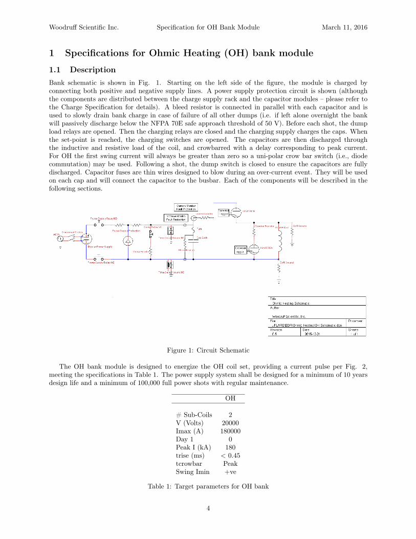
1.1 DescriptionBank schematic is shown in Fig. 1. Starting on the left side of the figure, the module is charged byconnecting both positive and negative supply lines. A power supply protection circuit is shown (althoughthe components are distributed between the charge supply rack and the capacitor modules – please refer tothe Charge Specification for details). A bleed resistor is connected in parallel with each capacitor and isused to slowly drain bank charge in case of failure of all other dumps (i.e. if left alone overnight the bankwill passively discharge below the NFPA 70E safe approach threshold of 50 V). Before each shot, the dumpload relays are opened. Then the charging relays are closed and the charging supply charges the caps. Whenthe set-point is reached, the charging switches are opened. The capacitors are then discharged throughthe inductive and resistive load of the coil, and crowbarred with a delay corresponding to peak current.For OH the first swing current will always be greater than zero so a uni-polar crow bar switch (i.e., diodecommutation) may be used. Following a shot, the dump switch is closed to ensure the capacitors are fullydischarged. Capacitor fuses are thin wires designed to blow during an over-current event. They will be usedon each cap and will connect the capacitor to the busbar. Each of the components will be described in thefollowing sections.
Figure 1: Circuit Schematic
The OH bank module is designed to energize the OH coil set, providing a current pulse per Fig. 2,meeting the specifications in Table 1. The power supply system shall be designed for a minimum of 10 yearsdesign life and a minimum of 100,000 full power shots with regular maintenance.
OH
# Sub-Coils 2V (Volts) 20000Imax (A) 180000Day 1 0Peak I (kA) 180trise (ms) < 0.45tcrowbar PeakSwing Imin +ve
Table 1: Target parameters for OH bank
4

Woodruff Scientific Inc. Specification for OH Bank Module March 11, 2016
0
0
0
0
0
0
00
I
V+
V-
I
V1
TD = 1n
TF = 1n
PW = 1
PER = 2
V1 = 0
TR = 1n
V2 = 5 R1
0.0004
R2671u
R18
100meg
IC= 10000+ C14
1.19e-7
R4
1m
L2
.000062
L5
3.7e-7
+-
+-
S1
S
VON = 1.0V
VOFF = 0.0V
R3
671u
V2
TD = .5m
TF = 1n
PW = 1
PER = 2
V1 = 0
TR = 100n
V2 = 5
K K12
COUPLING = .067K_Linear
+
-
+
-
S2
S
VON = 1
VOFF = 0
L1
.000062
L3
2.6e-7
R5
1e-4
C122.85m
C13
10n
C15
1.19e-7
R7
0.01m
C2
1e-8
IC= -10000+
R19
1m
Date/Time run: 02/22/16 14:29:51** Profile: "SCHEMATIC1-trans" [ c:\users\simon\dropbox\pppl-flare\cdr\full power\bank1 ohmic heating\p...
Temperature: 27.0
Date: February 22, 2016 Page 1 Time: 14:32:35
(E) trans.dat (active)
Time
0s 2ms 4ms 6ms 8ms 10msI(L3) V(L5:1,C12:2) I(L2)
0
40K
80K
120K
160K
200K
-20K
Figure 2: PSpice Schematic and Analysis
5

Woodruff Scientific Inc. Specification for OH Bank Module March 11, 2016
1.2 Full Assembly: moduleFig. 3 shows the full bank assembly mounted on two 48 inch square steel pallets.
Revisions
DescriptionRev Date ApprovedZone
Do Not Scale Drawing
Finish--
Material--
Unless Otherwise Specified:
Drawn
Checked
ENG Appr.
MFR Appr.
DateName
QA
Comments
Woodruff Scientific, Inc.
PPPL FLARE
Size
A
Drawing No.
CAD File Sheet
Rev
Scale
CAD Generated DrawingDo Not Manually Update
1:1 1 of 1
OH Capacitor Bank
0001 A
Dimensions in Inches
Tolerances: Fractional ±
Angular: Mach ± Bend ±
Two Place Decimal ±
Three Place Decimal ±
JES 2/19/16
97.
48.
Figure 3: Engineering design point for bank module
The full assembly must not have a footprint greater than 32sqft with a maximum of 64sqft for egressand maintenance, and must be engineered as a module that can be transported and installed onsite withonly a small number of connections (connections for 110V power, etc, see section below). The OH Bank andall related components will be mounted on 2 48"x48" standard pallets, total height under 50 inches, totalweight per pallet of 1200lbs. Assembly instructions must be provided.
6

Woodruff Scientific Inc. Specification for OH Bank Module March 11, 2016
1.3 Capacitors
Figure 4: Capacitor detail
The capacitors are expected to see reversal voltages during the experimental shots. The voltage reversalon the caps will be specified to be 80%. Each capacitor unit should be individually fused and self-protected.Energy dumping resistor(s) shall be specified for safe dissipation of stored energy (see below). The dissipationtime should be limited to the shorter of the relevant industrial standards or the experimental needs. TheOH bank will use 6 NL485-20KV Capacitors, by Richardson Electronics. They have a rated capacitance of485uF and a rated voltage of 20kVDC. They are rated for 80% discharge voltage reversal. The capacitorsare expected to survive at least 500,000 full power shots without failure, per cap manufacturer specificationsee appendix for the Richardson specification. In parallel with each capacitor is a bleed resistor. These are aredundant dump mechanism for the stored energy. These resistors are sized to discharge the bank to below50 volts over 12 hours. The bleed resistors are a passive “last resort” safing mechanism in case of failure of thewater dump or loss of buswork connections, allowing the operator to leave the bank overnight to dissipateits stored energy. The bleed resistor shown in Fig. 4 is a 40W 60MΩ Ohmite Mox-G (see spec in appendix).Shown also in Fig. 4 are the fuse wires, which are 4 15AWG bare copper wires soldered into ring terminals.Burn guard will be mounted to the cap with double-sided adhesive tape (e.g. 3M Command Strips).
1.4 Forward SwitchWherever practical and appropriate, PPPL prefers the following ignitron to be used. Ignitron model NL8900,by Richardson Electronics. For the this bank, the forward switch will be such an ignitron. The ignitrons areexpected to see reverse voltage and pulse currents. Life time of the ignitron contact shall not be significantlyshortened or the minimum design life of the equipment should be maintained. The ignitrons are expectedto survive a minimum of 10,000 full power shots without failure. The anode of the ignitron requires heating.This design will utilize a 500W infrared heater mounted close to the anode. The ignitron requires watercooling, provided by 1/4" NPT hose connected to a water chiller. Ignitrons are connected to the verticalbus bar using 3 copper braids terminated with ring terminals and bolted with 1/4-20 bolts (see machiningdrawings for details).
1.5 Crowbar SwitchThe crowbar switch on the OH bank utilize Ignitron model NL8900, by Richardson Electronics (see ap-pendix). One switch is used in the crowbar. This Ignitron uses the IG5F2-10 Ignitron Driver, also byRichardson Electronics. After the forward switch is fired, the crowbar will be fired after a delay correspond-ing to peak current. The anode of the Ignitron requires heating. This design will utilize a 500W infrared
7

Woodruff Scientific Inc. Specification for OH Bank Module March 11, 2016
Figure 5: Switch detail, calling out components and references to drawing numbers
heater mounted close to the anode. The ignitron requires water cooling, provided by 1/4" NPT hose con-nected to a water chiller. Ignitrons are connected to the bus bar using 3 copper braids terminated with ringterminals and bolted with 1/4-20 bolts (see machining drawings for details).
1.6 Buswork
Figure 6: Buswork detail with labels for machining drawings.
Buswork consists of busbars connected to the caps by use of brass adapters that are secured by 1/4-20bolts and have knife-edges that will bite into the copper busbars (see detailed call-out in Fig. 6. A largerbus is used to interconnect all the smaller capacitor buses which then feeds into the current limiting stainlesssteel resistor. Outgoing and return busbars are isolated from each other by use of multiple layers of mylarsheet, with sufficient overhang to meet the 2E+1 stand-off requirement. A 1mOhm overcurrent protection
8

Woodruff Scientific Inc. Specification for OH Bank Module March 11, 2016
resistor is provided in case of short failure, clamping the maximum current to tolerable thresholds for thecaps. The power supply should be properly insulated based on design. The rule of thumb to be followed is2E+1, where E is the maximum system voltage. All bus work should be taken into consideration so that theinductance does not limit the system performance.
1.7 Charging
Figure 7: Charging switch and connection detail.
The charging supply will consist of two TDK-Lambda supplies, one 402L-10kV-POS-208VAC and one402L-10kV-NEG-208VAC. The charge supplies are wired in series to create a ±10kV bipolar output. Thetwo output lines each include a series resistor to improve regulation and limit output current under faultconditions. The lines are then split to run a cable to each capacitor module. At the capacitor module, thecharge cable is connected across a diode that protects the charge supply in the event of a bank pre-fire (whenthe charge supply is connected to the bank). The diode prevents any bank reversal during pre-fire fromimposing a reverse voltage at the charge supply. After the diode is a resistor that limits the charge currentfor the bank (and limits the protection diode current under reversal). The final connection to the capacitorbuswork is made via a normally-open DPST Ross relay (E40-2PNO) which is only connected for charging,and is disconnected immediately prior to programmed discharge. Please refer to the separate specificationfor the charging supplies (treated as a separate sub-assembly). Charging cable is terminated at the bankwith a custom connector (see section on Connections)
1.8 DumpEach capacitor module includes a resistor sized to dissipate the full-charge energy of the bank. The resistormaterial is an aqueous solution of copper sulfate with brass electrodes in a polycarbonate reservoir. Theelectrolyte concentration is tuned to discharge the bank to below 50 volts (the NFPA 70E safety threshold)within 30 seconds. This dump rate was chosen based upon a conservative estimate of the time requiredfrom removal of the Kirk key at the operator station to entry of the bank enclosure. The dump sizing isalso designed to allow several sequential full-energy dumps at 3 minute intervals, but in this operation modethe resistor temperature shall be monitored remotely by the operator to ensure the temperature does notexceed 60C (as per ASTM C1055) and that the water level is maintained. The normally-closed dump relayon each module (Ross E40-NC) will be energized only during charge, and will be de-energized to engage thedump upon removal of the Kirk key or at any emergency stop or interlock break. A temperature sensor islocated on the outside lower section of each dump.
1.9 HarnessingThe harnessing sub-assembly comprises all of the interconnecting power cables from the CCDPS to theFLARE machine. The cabling will be triax of suitable current rating (see e.g. Dielectric Sciences specification
9

Woodruff Scientific Inc. Specification for OH Bank Module March 11, 2016
Figure 8: Dump detail with labels for major components.
in the Appendix). 10 cables will connect to the cable header located close to the switches and between thedumps. Cable trays will be used to route cables from the capacitor banks to the device.
1.10 Polarity switchingNo polarity switch is required for this module.
1.11 DiagnosticsDiagnostics must be provided to measure the forward current in the bus leading to the forward switch (seegray block on safety resistor in Fig. 6 for placement), the voltage of the bank module using a voltage divider,and the temperature of the over-current protection resistor, the temperature in the dump resistor and thetemperature at the anode of the ignitrons. Each of these diagnostic measurements must be transmittedalong a fiber-optic connection to the DAQ. Please see separate DAQ specifications for further information.
1.12 SafetyMonitoring (analog and digital voltage monitoring) will be required. A voltage divider at the bank will beused to monitor the charging voltage on the control computer (see specification for DAQ), and provide asignal for a panel-mounted analog indicator at the entry to the enclosure. The OH bank module will behoused in a bay that separated it from other bank modules. Each side of the bank module may be separatedby a 1/4 inch steel blast shield. The enclosure will be interlocked and procedures will be present to disablethe bank before personnel access.
1.13 Cooling requirementsIgnitron switches in the OH module require a connection to a water coolant supply to provide a minimumof 10 degrees of relative temperature difference between anode and cathode. Water coolant is provided byconnection of 1/4" NPT fittings on the base of the ignitron to a water chiller. See detailed specifications inthe appendix.
10
Woodruff Scientific Inc. Specification for OH Bank Module March 11, 2016
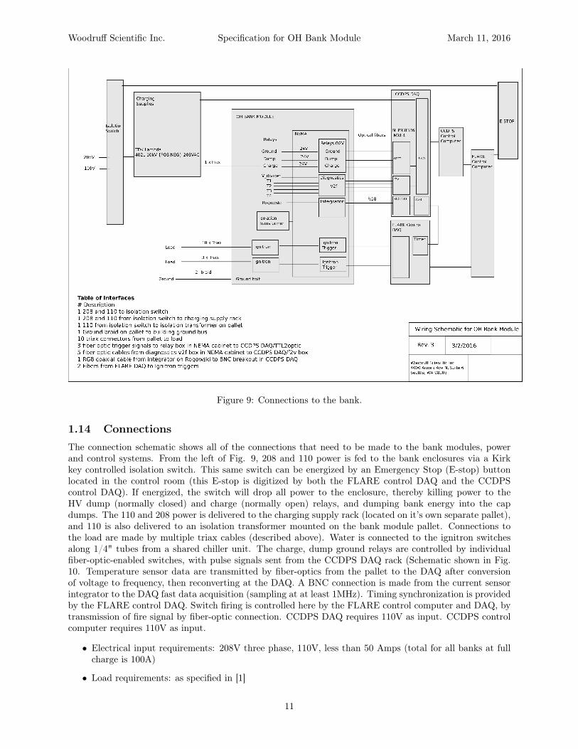
Figure 9: Connections to the bank.
1.14 ConnectionsThe connection schematic shows all of the connections that need to be made to the bank modules, powerand control systems. From the left of Fig. 9, 208 and 110 power is fed to the bank enclosures via a Kirkkey controlled isolation switch. This same switch can be energized by an Emergency Stop (E-stop) buttonlocated in the control room (this E-stop is digitized by both the FLARE control DAQ and the CCDPScontrol DAQ). If energized, the switch will drop all power to the enclosure, thereby killing power to theHV dump (normally closed) and charge (normally open) relays, and dumping bank energy into the capdumps. The 110 and 208 power is delivered to the charging supply rack (located on it’s own separate pallet),and 110 is also delivered to an isolation transformer mounted on the bank module pallet. Connections tothe load are made by multiple triax cables (described above). Water is connected to the ignitron switchesalong 1/4" tubes from a shared chiller unit. The charge, dump ground relays are controlled by individualfiber-optic-enabled switches, with pulse signals sent from the CCDPS DAQ rack (Schematic shown in Fig.10. Temperature sensor data are transmitted by fiber-optics from the pallet to the DAQ after conversionof voltage to frequency, then reconverting at the DAQ. A BNC connection is made from the current sensorintegrator to the DAQ fast data acquisition (sampling at at least 1MHz). Timing synchronization is providedby the FLARE control DAQ. Switch firing is controlled here by the FLARE control computer and DAQ, bytransmission of fire signal by fiber-optic connection. CCDPS DAQ requires 110V as input. CCDPS controlcomputer requires 110V as input.
• Electrical input requirements: 208V three phase, 110V, less than 50 Amps (total for all banks at fullcharge is 100A)
• Load requirements: as specified in [1]
11

Woodruff Scientific Inc. Specification for OH Bank Module March 11, 2016
• Cooling requirements: chiller for ignitrons (see specification attached)
• Environmental requirements: dust free, see below
• Control signals needed as inputs: ESTOP and triggers (see Fig. 9)
• Control signals as outputs: none.
Figure 10: Schematic for charge, dump and ground relay control.
1.15 Environmental requirementsThe entire CCDPS is specified to operate at room temperature, and will tolerate seasonal variations inhumidity without the need for any special AC, other than cooling lines to the ignitrons. Ideally the bankswill be placed in a dust-controlled environment (fans with filters, preferably with drywall to the ceiling),with minimal traffic to the enclosure.
12

Woodruff Scientific Inc. Specification for OH Bank Module March 11, 2016
2 References
References[1] Statement of Work for Design of Capacitor Charge/Discharge Power Supply (CCDPS) for FLARE
FLARE-CCDPS-150828, Revision 0, Sept. 9th 2015
3 Appendices
3.1 Engineering Drawings and Vendor Specs
Revisions
DescriptionRev Date ApprovedZone
Do Not Scale Drawing
Finish--
Material--
Unless Otherwise Specified:
Drawn
Checked
ENG Appr.
MFR Appr.
DateName
QA
Comments
Woodruff Scientific, Inc.
PPPL FLARE
Size
A
Drawing No.
CAD File Sheet
Rev
Scale
CAD Generated DrawingDo Not Manually Update
1:1 1 of 1
Bleed Resistor Channel
0001 A
Dimensions in Inches
Tolerances: Fractional ±
Angular: Mach ± Bend ±
Two Place Decimal ±
Three Place Decimal ±
G10 or other suitable insulating material
PCaB002
1.25 1.75
6.
4.
3.
1.
Figure 11: OH Bleed Resistor Channel
OH EF TF PF
H 8.125 8.125 6.25 6.75W 10.875 10.875 15 15
Table 2: Bus Clamp Dimensions by Bank (inches)
13

Woodruff Scientific Inc. Specification for OH Bank Module March 11, 2016
Revisions
DescriptionRev Date ApprovedZone
Do Not Scale Drawing
Finish--
Material
Unless Otherwise Specified:
Drawn
Checked
ENG Appr.
MFR Appr.
DateName
QA
Comments
Woodruff Scientific
PPPL FLARE
Size
A
Drawing No.
CAD File Sheet
Rev
Scale
CAD Generated DrawingDo Not Manually Update
1:1 1 of 1
PSwC001
0001 A
Dimensions in Inches
Tolerances: Fractional ±
Angular: Mach ± Bend ±
Two Place Decimal ±
Three Place Decimal ±Ignitron Switch - Copper
1/8" Copper
Welded
Weld
Weld 4-Off
Weld 4-Off
6.
.625
3.125
3.
.375Ø
45.°
9.75
10.Ø
12.
.25
Figure 12: Ignitron Cage - Copper
14
Woodruff Scientific Inc. Specification for OH Bank Module March 11, 2016
Revisions
DescriptionRev Date ApprovedZone
Do Not Scale Drawing
Finish--
Material
Unless Otherwise Specified:
Drawn
Checked
ENG Appr.
MFR Appr.
DateName
QA
Comments
Size
A
Drawing No.
CAD File Sheet
Rev
Scale
CAD Generated DrawingDo Not Manually Update
1:1 1 of 1
0001 A
Dimensions in Inches
Tolerances: Fractional ±
Angular: Mach ± Bend ±
Two Place Decimal ±
Three Place Decimal ±
Woodruff Scientific, Inc.
PPPL FLARE
Ignitron Cage - Stainless
Weld 2-Off
PPPL FLARE
Ignitron Cage - StainlessPSwC002
WeldedWelded
0.125" Stainless Steel unless indicated
Weld 4-Off
Weld 4-Off
8-32 x 3/4"3. .625
.625
5.Ø.375Ø
3.125
6.
45.°
9.75
10
1.25
.25
15.
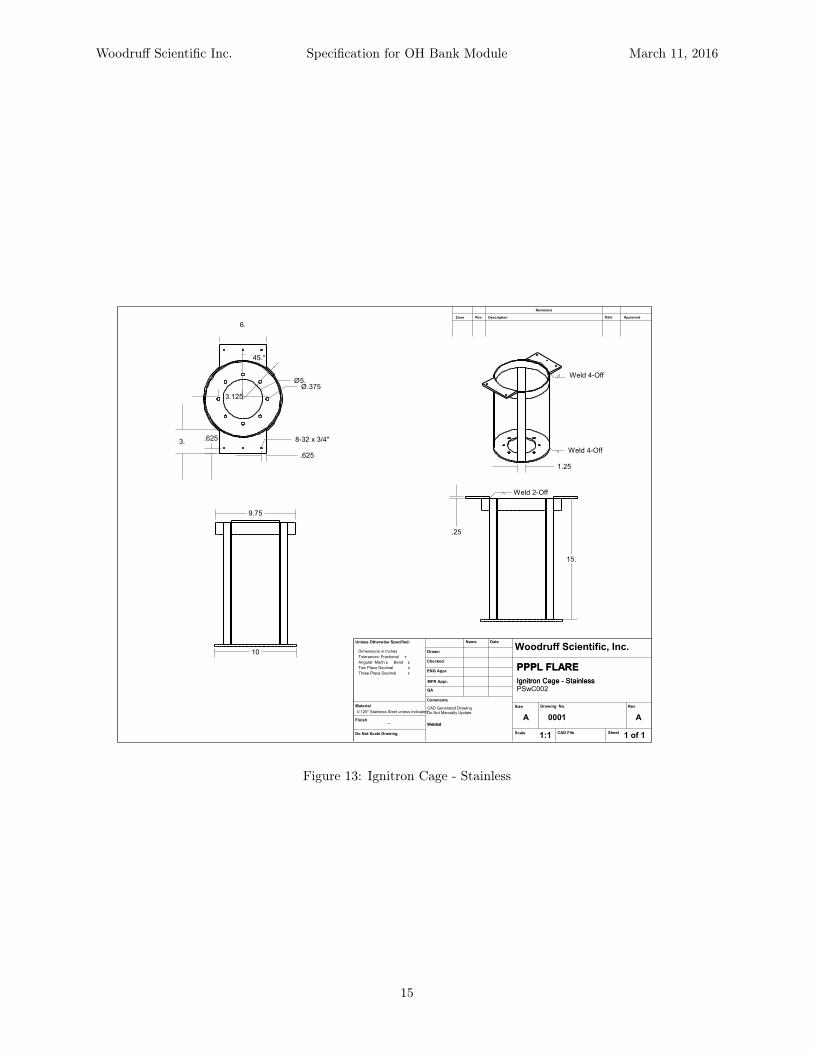
Figure 13: Ignitron Cage - Stainless
15
Woodruff Scientific Inc. Specification for OH Bank Module March 11, 2016
Revisions
DescriptionRev Date ApprovedZone
Do Not Scale Drawing
Finish--
Material
All Holes countersunk from bottom side
Unless Otherwise Specified:
Drawn
Checked
ENG Appr.
MFR Appr.
DateName
QA
Comments
Woodruff Scientific
PPPL FLARE
Size
A
Drawing No.
CAD File Sheet
Rev
Scale
CAD Generated DrawingDo Not Manually Update
1:1 1 of 1
OH Bus Upper
0001 A
Dimensions in Inches
Tolerances: Fractional ±
Angular: Mach ± Bend ±
Two Place Decimal ±
Three Place Decimal ±
1/4" Copper Sheet
PBuB001-OH
4.
67.875
7.42 14.1
26.25
6.
A
B10.
C
.25
.25
.25
.5
.164 v 0.31" x 82° 4OffØ
Detail A
.25 v 0.48" x 82°Ø
.25
Detail B
.25 v 0.48" x 82° 6OffØ
.75
1.5
1.25
Detail C
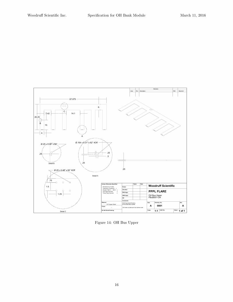
Figure 14: OH Bus Upper
16

Woodruff Scientific Inc. Specification for OH Bank Module March 11, 2016
Revisions
DescriptionRev Date ApprovedZone
Do Not Scale Drawing
Finish--
Material
All Holes Countersunk from Top side
Unless Otherwise Specified:
Drawn
Checked
ENG Appr.
MFR Appr.
DateName
QA
Comments
Woodruff Scientific
PPPL FLARE
Size
A
Drawing No.
CAD File Sheet
Rev
Scale
CAD Generated DrawingDo Not Manually Update
1:1 1 of 1
OH Bus Lower
0001 A
Dimensions in Inches
Tolerances: Fractional ±
Angular: Mach ± Bend ±
Two Place Decimal ±
Three Place Decimal ±
1/4" Copper Sheet
PBuB002-OH
67.875
4.
7.414.1
23.5
5.
12A
10.
B
Ø.25 v .48" x 82°
.25
.25 v 0.48" x 82°Ø.25
Detail A
.25 v 0.48" x 82° 6OffØ
.75
1.5
1.25
Detail B
Figure 15: OH Bus Lower
17

Woodruff Scientific Inc. Specification for OH Bank Module March 11, 2016
Revisions
DescriptionRev Date ApprovedZone
Do Not Scale Drawing
Finish--
Material--
Unless Otherwise Specified:
Drawn
Checked
ENG Appr.
MFR Appr.
DateName
QA
Comments
Woodruff Scientific
PPPL FLARE
Size
A
Drawing No.
CAD File Sheet
Rev
Scale
CAD Generated DrawingDo Not Manually Update
1:1 1 of 1
OH Bus Insulation
0001 A
Dimensions in Inches
Tolerances: Fractional ±
Angular: Mach ± Bend ±
Two Place Decimal ±
Three Place Decimal ±
Sheets of Mylar totalling 1/4"
PBuB003-OH
28.
9.
7.
4.4
11.1
70.875
.03 8-Off
Figure 16: OH Bus Insulation
18

Woodruff Scientific Inc. Specification for OH Bank Module March 11, 2016
Revisions
DescriptionRev Date ApprovedZone
Do Not Scale Drawing
Finish--
Material--
Unless Otherwise Specified:
Drawn
Checked
ENG Appr.
MFR Appr.
DateName
QA
Comments
Woodruff Scientific
PPPL FLARE
Size
A
Drawing No.
CAD File Sheet
Rev
Scale
CAD Generated DrawingDo Not Manually Update
1:1 1 of 1
Vertical Bus Support
0001 A
Dimensions in Inches
Tolerances: Fractional ±
Angular: Mach ± Bend ±
Two Place Decimal ±
Three Place Decimal ±
PBuR002-OH
G10 Channel Stock
2 Off
1.5
3.5
28.
1.4
2.
1.
.5
.25Ø
.5Ø
Figure 17: OH Bus Vertical Support - 2 Off
19
Woodruff Scientific Inc. Specification for OH Bank Module March 11, 2016
Revisions
DescriptionRev Date ApprovedZone
Do Not Scale Drawing
Finish--
Material--
Unless Otherwise Specified:
Drawn
Checked
ENG Appr.
MFR Appr.
DateName
QA
Comments
Woodruff Scientific
PPPL FLARE
Size
A
Drawing No.
CAD File Sheet
Rev
Scale
CAD Generated DrawingDo Not Manually Update
1:1 1 of 1
OH Vertical Bus Bar
0001 A
Dimensions in Inches
Tolerances: Fractional ±
Angular: Mach ± Bend ±
Two Place Decimal ±
Three Place Decimal ±
1/4" Copper Plate
PBuB004-OH
Bend
.625
.625
3.
8-32
1.75
3.
.75
1.5
.25Ø
6.
4.25
2.
17.65 .5Ø
2
4.25
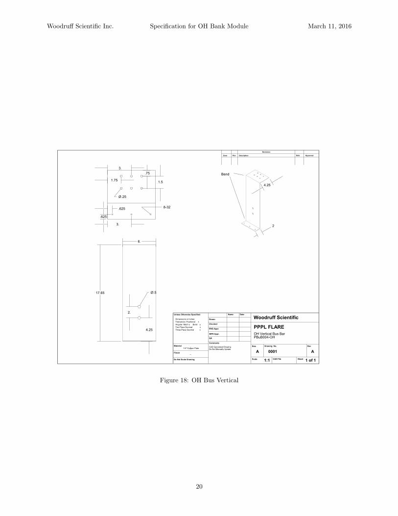
Figure 18: OH Bus Vertical
20
Woodruff Scientific Inc. Specification for OH Bank Module March 11, 2016
Revisions
DescriptionRev Date ApprovedZone
Do Not Scale Drawing
Finish--
Material--
Unless Otherwise Specified:
Drawn
Checked
ENG Appr.
MFR Appr.
DateName
QA
Comments
Woodruff Scientific
PPPL FLARE
Size
A
Drawing No.
CAD File Sheet
Rev
Scale
CAD Generated DrawingDo Not Manually Update
1:1 1 of 1
OH Bus Resistor
0001 A
Dimensions in Inches
Tolerances: Fractional ±
Angular: Mach ± Bend ±
Two Place Decimal ±
Three Place Decimal ±
PBuR001-OH
1/8" Stainless Steel Plate
Bend
4.
.25Ø
.75 .75
.75
1.5
4.125
4.
4.
2.
16.5
.5Ø
1.
.75
.25Ø
Detail A
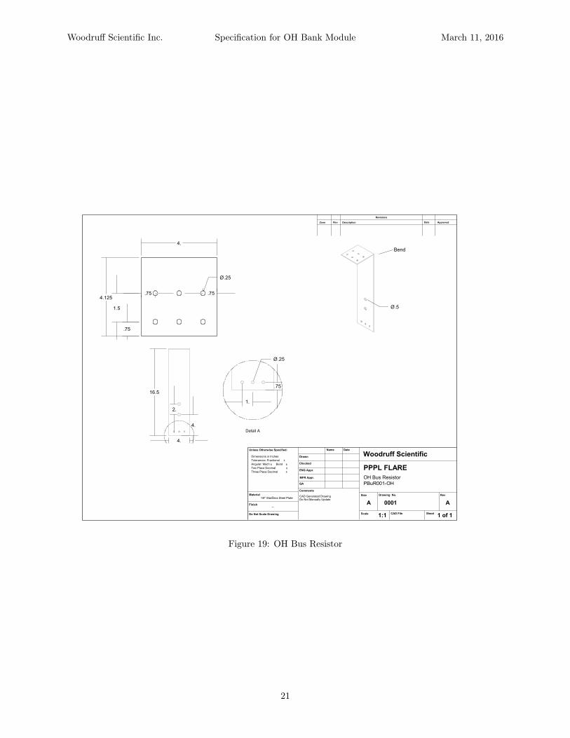
Figure 19: OH Bus Resistor
21

Woodruff Scientific Inc. Specification for OH Bank Module March 11, 2016
Revisions
DescriptionRev Date ApprovedZone
Do Not Scale Drawing
Finish--
Material
Unless Otherwise Specified:
Drawn
Checked
ENG Appr.
MFR Appr.
DateName
QA
Comments
Woodruff Scientific, Inc.
PPPL FLARE
Size
A
Drawing No.
CAD File Sheet
Rev
Scale
CAD Generated DrawingDo Not Manually Update
1:1 1 of 1
Bus Clamps
0001 A
Dimensions in Inches
Tolerances: Fractional ±
Angular: Mach ± Bend ±
Two Place Decimal ±
Three Place Decimal ±
1/4" G10 Plate
Fiberglass threaded rod and nuts
PBuC001 and PBuC002
PBuC002
PBuC001
PBuC003
PBuC001a
W
1.
.5
8.
.375Ø
H
.75
Figure 20: OH Bus Clamps (see Table 2 for table of dimensions)
22

Woodruff Scientific Inc. Specification for OH Bank Module March 11, 2016
Revisions
DescriptionRev Date ApprovedZone
Do Not Scale Drawing
Finish--
Material--
Unless Otherwise Specified:
Drawn
Checked
ENG Appr.
MFR Appr.
DateName
QA
Comments
Woodruff Scientific
PPPL FLARE
Size
A
Drawing No.
CAD File Sheet
Rev
Scale
CAD Generated DrawingDo Not Manually Update
1:1 1 of 1
Cable Header PBuH-OHEF
0001 A
Dimensions in Inches
Tolerances: Fractional ±
Angular: Mach ± Bend ±
Two Place Decimal ±
Three Place Decimal ±
Cu PlateFiberglass Threaded Rod
Plates are mirror images except holes for connectors
# of connectors varies by bank, see spec
PBuH002-OHEF
PBuH004
PBuH003
22.
2.
1.5
3.5
1.5
12. 6.
5.
14.
A 3
.625
1.25
2.875
17.125
.25
2
8-32 6off
PBH001-OHEF
1.5
2.
11.5
2.25
2.62
10-24
.703Ø
.196Ø
.75
60.°
Detail A
Figure 21: OH Cable Header
23

Woodruff Scientific Inc. Specification for OH Bank Module March 11, 2016
Revisions
DescriptionRev Date ApprovedZone
Do Not Scale Drawing
Finish--
MaterialBrass
Unless Otherwise Specified:
Drawn
Checked
ENG Appr.
MFR Appr.
DateName
QA
Comments
Woodruff Scientific Inc
Outer Cable Connector
Size
A
Drawing No.
CAD File Sheet
Rev
Scale
CAD Generated DrawingDo Not Manually Update
1:1 1 of 1
Cable to busbar connector
0001 A
Dimensions in Inches
Tolerances: Fractional ±
Angular: Mach ± Bend ±
Two Place Decimal ±
Three Place Decimal ±
6 Places
Round Edges .010"
for outer conductor PHaC001
A A
.568
2.000
2.00Ø
.86Ø
.703Ø
1.500Ø
.196Ø
.25
.01
.02
.94 .86
Section A-A
Figure 22: Outer Triax Connector
24
Woodruff Scientific Inc. Specification for OH Bank Module March 11, 2016
Revisions
DescriptionRev Date ApprovedZone
Do Not Scale Drawing
Finish--
MaterialBrass
Unless Otherwise Specified:
Drawn
Checked
ENG Appr.
MFR Appr.
DateName
QA
Comments
Woodruff Scientific Inc
Center Cable Connector
Size
A
Drawing No.
CAD File Sheet
Rev
Scale
CAD Generated DrawingDo Not Manually Update
1:1 1 of 1
Cable to busbar connector
0001 A
Dimensions in Inches
Tolerances: Fractional ±
Angular: Mach ± Bend ±
Two Place Decimal ±
Three Place Decimal ±
for center conductor PHaC002
Drill and tap #10-24
B B
1.43
.25
.500Ø.545.°
Section B-B
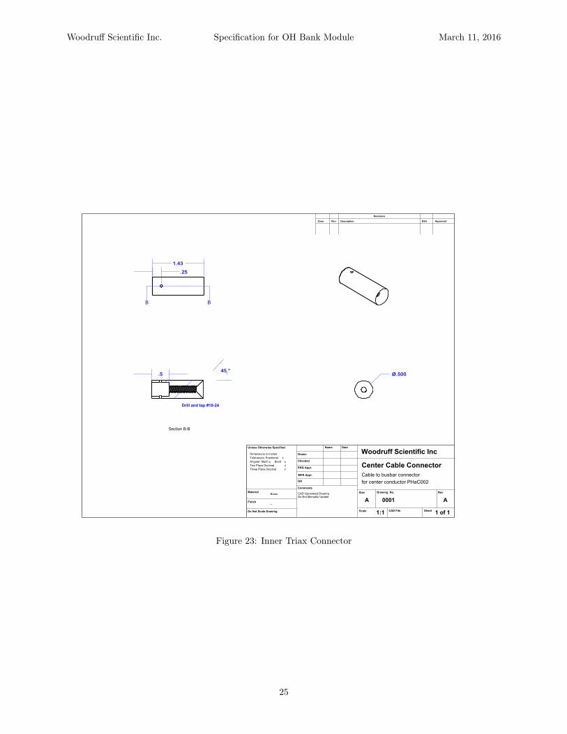
Figure 23: Inner Triax Connector
25

Woodruff Scientific Inc. Specification for OH Bank Module March 11, 2016
Revisions
DescriptionRev Date ApprovedZone
Do Not Scale Drawing
Finish--
Material--
Unless Otherwise Specified:
Drawn
Checked
ENG Appr.
MFR Appr.
DateName
QA
Comments
Woodruff Scientific
PPPL FLARE
Size
A
Drawing No.
CAD File Sheet
Rev
Scale
CAD Generated DrawingDo Not Manually Update
1:1 1 of 1
Dump Lid
0001 A
Dimensions in Inches
Tolerances: Fractional ±
Angular: Mach ± Bend ±
Two Place Decimal ±
Three Place Decimal ±
20.
.75Ø
Figure 24: Dump Lid
26

Woodruff Scientific Inc. Specification for OH Bank Module March 11, 2016
Revisions
DescriptionRev Date ApprovedZone
Do Not Scale Drawing
Finish--
Material--
Unless Otherwise Specified:
Drawn
Checked
ENG Appr.
MFR Appr.
DateName
QA
Comments
Woodruff Scientific
PPPL FLARE
Size
A
Drawing No.
CAD File Sheet
Rev
Scale
CAD Generated DrawingDo Not Manually Update
1:1 1 of 1
Dump Tank
0001 A
Dimensions in Inches
Tolerances: Fractional ±
Angular: Mach ± Bend ±
Two Place Decimal ±
Three Place Decimal ±
18.
26.
1.
15.
Figure 25: Dump Tank
27

Woodruff Scientific Inc. Specification for OH Bank Module March 11, 2016
Revisions
DescriptionRev Date ApprovedZone
Do Not Scale Drawing
Finish--
Material--
Unless Otherwise Specified:
Drawn
Checked
ENG Appr.
MFR Appr.
DateName
QA
Comments
Woodruff Scientific, Inc.
PPPL FLARE
Size
A
Drawing No.
CAD File Sheet
Rev
Scale
CAD Generated DrawingDo Not Manually Update
1:1 1 of 1
Dump Eyehook Mount Bracket
0001 A
Dimensions in Inches
Tolerances: Fractional ±
Angular: Mach ± Bend ±
Two Place Decimal ±
Three Place Decimal ±
Attaches to dump post
Steel
PDuS002
.75Ø
3.
.75Ø
2.25
3.
Figure 26: Dump Stick Eyehook Bracket
28

NL485-20KVDCHIGH DENSITY CHARGE TRANSFER CAPACITOR
40W267 Keslinger RoadPO Box 393, LaFox, IL 60147 USA
1.800.348.5580 (USA & Canada)1.630.208.2200 (International)www.rell.com | [email protected]
Electronics assumes no responsibility for any errors which may appear in this document. No part of this document may be copied or reproduced in any form or by any means without the prior written consent of Richardson Electronics, Ltd.
Rev. 1/11/2016
HDCT 20kV 485 µF Pulse Capacitor
Type HDCT
Rated voltage UNDC20kVDC
Rated capacitance CN485 µF
Capacitance tolerance ±5.0%
Rated Discharge Current Ip30kA
Max Discharge Current (system fault) Î 75kA
Rated Discharge Voltage Reversal % 80%
Self inductance LS<200 nH
Int. series resistance RS< 10mΩ
Loss factor tanδ < 1.0 x10⁻³ / 100 Hz
Life Expectancy (90 % survival) 500,000 discharges
Operating temperature Θmin/ max -40°C / +70 °C
TechnologyMetalized Polypropylene
film, dry type, SH
Dimensions(mm3) 590×265×725

NL485-20KVDCHIGH DENSITY CHARGE TRANSFER CAPACITOR
40W267 Keslinger RoadPO Box 393, LaFox, IL 60147 USA
1.800.348.5580 (USA & Canada)1.630.208.2200 (International)www.rell.com | [email protected]
Electronics assumes no responsibility for any errors which may appear in this document. No part of this document may be copied or reproduced in any form or by any means without the prior written consent of Richardson Electronics, Ltd.
Rev. 1/11/2016
M14
H+100
4-M10
H±
2
W±
2
L±2
A±2
L-40
W-40
Specification L(mm) W(mm) H(mm) A(mm)
μF 590 265 725 30020kV 485

NL8900IGNITRON
© 2008 RICHARDSON ELECTRONICS, LTD. RICHARDSON ELECTRONICS, LTD AND ITS AFFILIATES RESERVE THE RIGHT TO MAKE CHANGES TO THE PRODUCT(S) OR INFORMATION CONTAINED HEREINWITHOUT NOTICE. RICHARDSON ELECTRONICS ASSUMES NO RESPONSIBILITY FOR ANY ERRORS WHICH MAY APPEAR IN THIS DOCUMENT. NO PART OF THIS DOCUMENT MAY BE COPIED ORREPRODUCED IN ANY FORM OR BY ANY MEANS WITHOUT THE PRIOR WRITTEN CONSENT OF RICHARDSON ELECTRONICS, LTD.
The NL8900 is a convection cooled ignitron for use as a high energyswitch in capacitor discharge circuits. The NL8900 is capable ofhandling peak voltages of 35 kV and peak currents up to 300 kA.
July 09, Rev A
GENERAL DATA
Electrical:Cathode Spot Starting IgnitorNumber of Electrodes
Anode -----------------------------------------------1Cathode -------------------------------------------- 1Ignitors ----------------------------------------------2
Inductance (approximate) ----------------------------200 nh
Mechanical:Envelope ------------------------------------------------ Stainless SteelAnode Material------------------------------------------ Stainless SteelMounting Position -------------------------------------Axis Vertical, Anode UpNet Weight ----------------------------------------------24 lb (10.9 kg)Diameter ------------------------------------------------ 7.25"Seated Height (Nominal) ----------------------------10.75"
Ignitor Ratings:Voltage MIN MAXOpen Circuit (Ignitor +) 1000 35000 VInverse (Ignitor -) ------ 5 VCurrent, Short Circuit 500 2000 ALength of Firing Pulse,1/2 Sine Wave 5 10 µs
Thermal:Type of Cooling ----------------------------------------Inlet Water Temperature (MIN) ---------------------10 °CInlet Water Temperature (MAX) --------------------30 °CWater Flow (At MAX Current)------------------------3.0 GPMCathode Temperature (MAX) ---------------------- 35 °CAnode Header Temperature (MAX) -------------- 55 °CAmbient Temperature --------------------------------10 to 30 °CAnode to Cathode Temperature -------------------(Note 1)
Liquid

WARNING! USING SIMULTANEOUS MAXIMUM RATINGS WILL SEVERELY DETERIORATE IGNITRON LIFE!
Notes:
1) To prevent mercury condensation on the anode and anode seals, the anode header temperature should be 10°C higher thanthe cathode temperature at all times. Before operation, elevate the temperature of the anode area, with respect to the cathode,long enough to remove any mercury from the top portion of the ignitron.
2) Rate of rise depends upon the external circuitry.
Tube Life Considerations
The method used to determine the life expectancy of an ignitron varies according to the application and it is necessary toconsider the various types separately. It must be understood that the ratings specified are absolute limits. It is the responsibil-ity of the equipment designer to ensure that the specified limits cannot be exceeded under the worse possible conditions ofcomponent tolerance, voltage fluctuation, and load variation.
A general rule of thumb: To obtain longer life, the ignitron must be operated at lower levels. Typically, life may be increased 10Xif either the voltage or current is halved.
Ignitrons are robust high current switching devices. The current ratings may be exceeded to some extent without destroyingthe ignitron but with the consequence of reduced life.
IGNITOR
The ignitor is a small rod of semiconducting material with a pointed end that is partially immersed into the cathode pool. Whena suitable current pulse is passed through the ignitor-mercury junction (with the ignitor being positive with respect to thecathode pool) forms a cathode spot on the surface of the mercury and free electrons are emitted. If the anode is sufficientlypositive with the cathode at this time, an arc will form between the cathode and anode. Once the arc is initiated, the ignitor hasno further control and the ignitron continues to conduct until the voltage across the ignitron falls below the ionization potentialof the mercury vapor.
In capacitor discharge circuits the ignitron has to pass a very high current and the conditions are naturally harmful to theignitron. The mercury pool and the ignitor itself will become contaminated and the best life will be obtained if a high energypulse is applied to the ignitor. Under these conditions a pulse from a separate excitation circuit containing a 1uf capacitorcharged from 1500V to 3000V will provide 1 to 4.5 Joules of energy to the ignitor. Richardson Electronics endorses NationalElectronics Ignitrons using these parameters. Considering the wide range of ignitors available across the range of ignitronsproduced, Richardson Electronics recommends that an ignitor pulse providing 4 to 7 Joules is optimal.
Page 2
Maximum RatingsDamped Discharge Ringing Discharge
Peak Anode VoltageForward -------------------------------- 35,000 ------------------- 35,000 VInverse --------------------------------- 35,000 ------------------- 35,000 V
Critical Anode Starting Voltage (MIN) 100 ------------------- 100 VAnode Current
Peak ------------------------------------ 300,000 ------------------- 300,000 ARate of Rise of Current ------------------- (Note 2) ------------------- (Note 2)Discharge (Rep Rate) Typical ---------- 2 ------------------- 2 Per MinuteTotal Charge (Per Minute) --------------- 250 ------------------- 250 CoulombsIonization Time ------------------------------ 0.5 ------------------- 0.5 µsVoltage Reversal --------------------------- None ------------------- 100 %

Page 3
AVAILABLE ACCESSORIES
Part Number Description
1K958-Series Ignitor Tulip Clip/Cable Assembly (Various options available, check with your local Richardson representa-tive for details.)
IG5F2-10 Ignitor Trigger Module (Works on all National Ignitrons.)
MOUNTING
The performance and life of the ignitron is greatly improved if it is operated in a field free space. Magnetic fields tend toforce the arc toward the tube sidewall and aggravate sidewall arcing. Metal vapor produced by sidewall arcing is one of themajor contributors to ignitor wetting. We recommend a coaxial type mounting to minimize field effects. See Page 5 for details.
INSTALLATION INFORMATION
RECOMMENDED CONDITIONING BEFORE INITIAL USE - The ignitron is in high voltage operating condition beforeleaving the factory. Shipping tends to redistribute mercury throughout the ignitron making certain conditioning steps desirablebefore installation.
Heat Conditioning - Before applying voltage, heat anode stud to 100-1250C (keeping cathode near room temperature) for twohours minimum. This drives mercury away from anode and anode seal area.
Voltage Conditioning (after Heat Conditioning) - Apply 110% of operating voltage (preferably DCV) or up to 110% of ratedmaximum voltage across ignitron (anode positive and ignitor not connected) with a series combination of a 1 to 4 uf capacitorand a 1 ohm resistor in parallel with the ignitron. NATIONAL will replace any ignitron that will not hold off minimum voltage atinitial test when caused by a manufacturing defect. Additional conditioning at higher voltages is recommended to stabilize theignitron after shipping. Slowly increase voltage above minimum. Breakdown may occur but the ignitron will attain a Hi-PotStabilization Voltage of approximately 125% of operating voltage, or up to 125% of rated maximum voltage.
NOTE: The time required for conditioning to Hi-Pot Stabilization Voltage can be reduced by using a variable ac voltagesource connected directly across the ignitron (ignitor not connected). Slowly increase the voltage; limit the current to 30milliamperes maximum.
RECOMMENDED PRACTICE AFTER INITIAL USE - Mercury condensed in the anode and anode seal area greatlydecreases the ignitron's voltage hold-off ability. Heat conditioning before initial use complements proper mercury distributionbefore the ignitron is first placed in operation. Once in operation, maintain a thermal gradient so that the anode area is at least10°C greater than the cathode. This is also true during any cooling period. The anode and anode area must not cool faster thanthe cathode.
The ignitor becomes susceptible to damage by movement of mercury after use in a capacitor discharge or crowbarapplication. For maximum life, we recommend that an ignitron not be moved until end-of-life once it has been placed in service.
LIFE AND WARRANTY
Richardson Electronics, Ltd. warrants the tube types listed above to be free from defects of design, material, and work-manship when received and, after receiving Recommended Conditioning Before Initial Use, to operate satisfactorily when firstinstalled and, if used within ratings, to give a minimum of 1000 operations. No adjustment will be made if the tube is not placedin service within six months after date of shipment by manufacturer. This warranty expires 12 months after date of shipment bymanufacturer.
National High Voltage Switching Ignitrons have an expected life of many times the warranted number of operations in mostapplications. Operating within the recommended ratings and following the Recommended Practices After Initial Use willgreatly increase the life or operations obtained.

OUTLINE DRAWING
Page 4
NOTE: The mounting flange attached to the bottom of the tube can be modified in most cases for compatibility with the userssocket. In all cases coaxial returns "squirrel cages" are recommended. The anode contact must NOT be ridged with respectto the cathode and the flexible anode connection MUST absorb all buss bar movement.


1. General
The IG5F2-10 Ignitron driver is designed to meet the specifications for triggering all ignitrons. Italso provides a trigger isolation capability of 25 kV. Its specifications are:
Stored Energy: 4 Joule at 1.0 Hz.; 3 J at 2 Hz.
Open Circuit Voltage: 1.80 kV at 1.0 Hz.
Current: 370 A output into typical ignitron ignitor (1 Hz.)
AC Input Voltage: 100 - 125 VAC input or 200 - 250 VAC input using internal slideswitch. Failure to set the unit properly when using the highervoltage will destroy the unit.
Input Pulse: 5 V TTL if fiber optic transmitter accessory board is usedNote that most 5 - 10 mA sources will drive this with 3 m cable.
Input Pulse Duration: 3 - 100 usec
Output Voltage Isolation: 25 kV to the input voltage
Fuse: 1/4 A internal
Supplied Fiber: 10 m. standardHP Versatile Fiber Type
Trigger Delay: 1200 ns. Typical
Status Indicators: TRIG TEST (See figures for TRIG TEST output characteristics)PS STATUS
Storage Temperature: -20 C - 45 C
Operating Temperature 5C - 40 C
2.0 Installation
Connect a versatile fiber trigger signal to the input fiber optic. The BNC/fiber adapter may beused to supply the trigger to the unit by applying a 5 - 15 V pulse to the BNC. TTL signalswhich meet typical TTL requirements will trigger the unit (5 V, 5 mA).
Connect the output marked Ignitor to the Ignitor pin, and connect the output marked Cathodeto the cathode. These connections should be secure and capable of conducting 400 A pulsed.
Open the unit and check the internal switch to assure that the power is set to the type of powerline you plan to use. If the internal power switch is not set correctly the unit may fail. Thefactory setting is always for 220 VAC. Connect the input power (220 VAC nominal or 110 VACnominal) to the AC receptacle once the settings of both switches are assured. If a poweredtrigger module has been supplied, check the settings of that unit before use.
Pulse the unit. Check the connections without HV applied to the ignitron to make sure that thecontacts are not arcing. The unit will make an audible ticking noise when triggered.
3.0 Mounting
A template for mounting the unit is appended. Studs used are Metric system M8.
4.0 Applications
The IG5-F is an ignitron driver supplied with the capability for isolation of the output. Forcircuits where the cathode is floating, such as series ignitron applications, the circuit can derivepower from the external circuit:
Circuit A Recomended Wherever Possible
In circuit A, the cathode of the ignitron is grounded. If this circuit can be used, cooling of theignitron jacket is simplified, along with triggering and monitoring. The unit power is connectedto line voltage, the fiber is inserted into the driver, and the unit triggers with each light pulse. The input power ground should be grounded (IEC plug and chassis ground).
Circuit B Lower Value Biases
In circuit B, the cathode of the ignitron is at some potential up to 25 kV from ground. If thiscircuit can be used, heating of the anode insulator is simplified, along with triggering andmonitoring. The unit power is connected to line voltage, the fiber is inserted into the driver, andthe unit triggers with each light pulse. An MOV of appropriate voltage connected from either ofthe line voltages (preferably neutral if such exists) to the preferred earth ground may be desirable. No voltage can exceed 25 kV relative to ground. The input power ground should be grounded(IEC plug and chassis ground).
Circuit C Floating Ignitron Powered by AC
In circuit C the circuit derives its power from AC voltage, but neither the cathode or anode isgrounded. The voltage difference betweeen the cathode/ignitor and anode must not excede 25kV including during transients. No voltage can exceed 25 kV relative to ground.

Igni tron
Cathode
Ignitor
+V In
)
Fiber in
Igni tron
Cathode
Ignitor-V In Limited to 25 kV
)
Fiber in
IG5-F
Igni tron
Cathode
Ignitor
C) No Ground - Power From AC Lines
Fiber in
IG5-F
-V In Limited to 25 kV
BNC/Fiber Adapter
BNC/Fiber Adapter
BNC/Fiber Adapter
In. Volt Switches
IG5-F
In. Volt Switches
IG5-F
In. Volt Switches
123 IEC
123 IEC
123 IEC
+V In Limited to 25 kV
In. Volt Switches
Figure 1 Application scenarios. The metal box should always be grounded.
5.0 Mounting
All parts are mounted to the enclosure. In order to mount the box, drill holes as described in theappended print, or use the template supplied.
6.0 Grounding
The box is designed for grounded operation. If floating operation is neccessary, the signal sourceand power source must be floated to the same potential. The difference between the powervoltage and the box voltage should not exceed 700 V peak.
7.0 Power Supply Voltage Monitor
The monitor labeled PS Status has an output when the power supply driving the SCR is ready. This will fail to light if the 600 V internal power supply or SCR fails.

Fig. 2 Short Circuit Monitor and Current.
Fig. 3 monitor and open circuit voltage
Figure of TRIG TEST output characteristic
Figure 2 shows the current in the output along with the monitor output for the case where theignitron ignitor fires immediately. The montor is on for 10 - 15 microseconds and its main pulsestarts within 2 microseconds of trigger initiation. This corresponds to nominally goodperformance.
Figure 3 shows the open circuit/open ignitor case. A pulse after saturation of the transformer,delayed by approximately 5 microseconds. In most situations, the pulse should appear in 4microseconds or less time after initition of the pulse from the fiber.

SPECIFICATIONS IG5F2-10
The IG5F2-10 Ignitron driver is designed to meet the specifications for triggering all ignitrons. Italso provides a trigger isolation capability of 25 kV. Its specifications are:
Stored Energy: 4 Joule at 1.0 Hz.; 3 J at 2 Hz.
Open Circuit Voltage: 1.80 kV at 1.0 Hz.
Current: 370 A output into typical ignitron ignitor (1 Hz.)
AC Input Voltage: 100 - 125 VAC input or 200 - 250 VAC input using internal slideswitch. Failure to set the unit properly when using the highervoltage will destroy the unit.
Input Pulse: 5 V TTL if fiber optic transmitter accessory board is usedNote that most 10 mA sources will drive this with 3 m cable.Longer cables will require more current
Input Pulse Duration: 3 - 100 usec
Output Voltage Isolation: 25 kV to the input voltage
Fuse: 1/8 A internal - 220 VAC; 1/4A internal 110 VAC
Supplied Fiber: 10 m. standardHP Versatile Fiber Type
Trigger Delay: 1200 ns. Typical
Status Indicators: TRIG TEST (See figures for TRIG TEST output characteristics)PS STATUS

Daniel S Erickson
Daniel S Erickson
NOTES:

IG-5-F-T2 Ignitron/Thyratron Driver Multiple Trigger Output Accessory
The IG-5-F-T4 is a 2 output trigger driver for North Star Ignitron and Thyratron drivers. Itconsists of a BNC high impedance input, a pulse amplifier, and 4 trigger output channels. Thespecifications are:
Power Supply Input Voltage: 100 - 260 V(Note: Power Supply is CE marked)Input Power Connection Standard IEC320 as used on most computers
Input Voltage: 2.4 V on 0.8 V offInput Voltage: 15 V maxInput Current: 10 uAInput Pulse Duration: 100 ns. Minimum
Output Pulse Power 5 dbmOutput Power Risetime Max. 85 ns. Output Pulse Duration Input pulse duration- 30 ns. min Output Delay Time 75 ns. typical Output Power Peak Wavelength 650 nm.
Output Fiber Specification
Type: PlasticDiameter 1 mmBrand Hewlett PackardPart Number HP 3510 Simplex or HP 3610 Duplex
Notes on cable: Do not bend Fiber Optic Cable with a radius ofcurvature of less than 4 cm. The light signal dropssignificantly for tight bends.
Application
The unit is designed to simultaneously trigger multiple ignitrons or thyratrons. The unit shouldbe connected to a TTL or higher input voltage (15 V Max.). It produces an output pulse of thesame duration.


402 Series Data SheetHigh Voltage Power Supply
Capacitor Charging and DCOutput Voltage from 1kV - 50kV
Output Power 4kJ/sec or 4kWFull local and remote control
www.us.tdk-lambda.com/hp

402 Series SpecificationIndustry standard rack mount capacitor charging and DC power supplies with 4kJ/sec rat-ing for capacitor charging, or 4kW rating in continuous DC applications.
Average Capacitor Charging Power 4,000 Joules/sec (½CV2 x Rep Rate)
Peak Capacitor Charging Power 5,000 Joules/sec (½CV2 ∕ tcharge)
Average Continuous DC Power 4,000 Watts
Output Voltage Range 1, 2, 4, 5, 10, 15, 20, 30, 40, 50kV, variable from 10-100% of rated
Polarity Available as fixed Positive or Negative. Please specify at time of ordering
HV Output Cable 1-39kV Models - DS2124 Coaxial cable with proprietary HV connector
40-50kV Models - DS2214 Coaxial cable with proprietary HV connector
HV Insulating Medium Exxon Mobil Univolt N61B or equivalent insulating oil
AC Input Voltage 208VAC (180-264), 3Ø or 400VAC (340-460), 3Ø + N, specify at time of ordering
AC Input Current 20A/15A
AC Connector UL/CSA approved terminal block. 3Ø + for 208VAC, 3Ø + N + for 400VAC
AC Line Contactor UL/CSA approved AC line contactor (standard on 402L and 402S, option for 402OEM)
Power Factor Passive PFC pf = 0.85 at full load and nominal AC line
Efficiency Better than 85% at full load
Front Panel 402L - Voltage Control, Voltage & Current Meters, Status Indicators
402S - On/Off Switch, Status Indicators
402-OEM - Blank front panel
Stability 0.2% per hour after 1 hour warmup
Temperature Coefficient 100ppm per °C typical
Stored Energy Less than 0.3J all models
Pulse to Pulse Repeatability ±2% to 1000Hz, consult factory for higher rep rates
Dimensions - inches (mm) 19 (483) W x 7 (178) H x 17 (432) D
Weight - lbs (kg) 65 (30)
Ambient Temperature Storage: -40 to +85°C. Operating: -20 to +45°C
Altitude Storage: 40,000ft (12,000m), Operating: 9,900ft (3,000m)
Humidity 10-90%, non-condensing
Protection Open/short circuits, Overloads, Arcs, Overtemp, Overvoltage, Safety Interlock
Remote Control (all models) Via 25-pin D-sub connector on rear of unit, Signals include, Vprogram (0-10V), HV Enable/Reset, Inhibit, Summary Fault, Load Fault, Vanalog, Vpeak
Accessories 10ft HV cable, operating manual
Options EN - Low Enable. Replaces standard high enable
5V - 0-5V Analog programming. Replaces standard 0-10V programming.
LP - Latching Overload Protection, requires HV reset after overload fault
DC - Continuous DC operation
CT - AC line contactor (option for 402OEM models only, standard on 402L and 402S)
Double terminated HV cable, and mating bulkhead connector
Ordering Info Model - XXkV - POS (or NEG) - YYYVAC - ZZ (options)
Ordering Examples 402L-10kV-POS, 402S-1kV-NEG-DC, 402-OEM-50kV-POS-400VAC
All specifications subject to change without notice
• Power rating of 4kJ/sec, 5kJ/sec peak• Output Voltages from 0-1kV to 0-50kV• Compact air cooled rack mount package• Efficient IGBT based resonant inverter• Excellent pulse to pulse repeatability• 208 or 400VAC 3Ø input voltage• Comprehensive remote control interface
• UL Approved AC line contactor (optional for OEM models)• Ultra reliable and rugged industry standard design• Passive PFC (pf = 0.85)• Full local output voltage and HV On/Off controls (L version)• Simple parallel operation for higher power• Lab, Slave, or OEM front panel options
402 Series Data Sheet1 |

402 Series Data Sheet | 2
402 Series Mechanical Details402L Front View 402L Rear View
Outline Drawings
1 2 3 4 5 6 7 8 9 10 11 12 13 14 15
1 - HV On/Off Push Buttons (L model only)2 - Status Indicator LEDs (L and S models only)3 - Local/Remote Keyswitch (L model only)4 - 10-Turn HV Output Control (L models only)5 - View Set Push Button (L models only)6 - Output Voltage and Current Displays (L models only)7 - Power Switch (L and S models only)
Notes:1 - Chassis slide mounting pattern matches General Devices CT series or equivalent with 3.875" hole spacing.2 - Cooling air enters rear of unit and exits at either side. Do not block air vents or cooling fan and allow several inches of clearance at rear of unit.3 - Allow 6" bend radius at rear of unit for HV cable.
8 - HV Output Connector9 - Ground Stud10 - Inhibit BNC (L models only)11 - Cooling Fan12 - Slave Supply Programming Connector (L models only)13 - Remote Programming Connector14 - AC Input Terminal Block15 - Interlock Terminals (L and S models only)
+
3 N
+
REMOTE
TO SLAVE
REMOTE
TO SLAVE
INHIBIT
INTE
RLO
CK!A
kV
STATUS
%
%
HV ON
CONTROL
10 TURN INCADJUST
OVERTEMP
LOAD FAULT
END OF CHARGE
INHIBIT
HV OFF
POWER
LOCALREMOTEOFF
VIEW SET
HV OFF
HV ON
INTERLOCK OPENCURRENT
VOLTAGE
1401201008060400 20
1101008060100 5030 704020 90
MODEL 402L
7" /
178m
m
19" / 483mm 17" / 432mm
17" / 432mm
Chassis slide mounting holes

SuplitecRua Sena Madureira 455, Belo Hte - 31340-000 Tel: +55-31-3498 1177, Fax: +55-31-3441 0841Email: [email protected], Web: www.suplitec.com.br
AcMax De MexicoRosas 139 Col. Bugambilias. Puebla, Pue. C.P. 72580Tel: +52-800-211-0060, Fax: +52-264-1445Email: [email protected], Web: www.acmax.mx
Electronics Optics Research, Ltd4-26-19 Koenji-MinamiSuginami-ku, Tokyo 166-0003 Tel: +81-333-145699, Fax: +81-333-142333Email: [email protected], Web: www.eor.jp
TDK-Lambda Shanghai Office2nd Floor of Building No.1, No.15 Guiqing Road,Shanghai, 200233 P.R. ChinaTel: +86-21-64850777, Fax: +86-21-64850666Email:[email protected] Web: www.cn.tdk-lambda.com
TDK-Lambda MalaysiaNo.7.3, 7th Floor, Jaya Shopping Center,Jalan Semangat Section 14, 46100Petaling Jaya Selangor, D.ETel: +60-3-7957-8800 Fax: +60-3-7958-2400Web: www.tdk-lambda.com.my
TDK-Lambda Singapore1008 Toa Payoh North # 06-01/08Singapore 318996Tel: +65-6251-7211 Fax: +65-6250-9171Web: www.se.tdk-lambda.com
TDK-Lambda India#526, Ground Floor, 10th Main, 7th Cross, Jeevanbhimanagar, Bangalore 560 075, Karnataka, India Tel : +91-80-43550500, Fax :+91-80-43550501Email: [email protected] www.in.tdk-lambda.com
PaR Systems (Pty) Ltd.Pretoria, South Africa Tel: +27-12-5480370, Fax: +27-12-5480447Email: [email protected]: www.sdilasers.com
PHILIPPINES
TDK-Lambda Americas Inc., High Power Division405 Essex Rd. Neptune, NJ 07753Tel: +1-732-922-9300, Fax: +1-732-922-1441E-mail: [email protected]: www.us.tdk-lambda.com/hp
TMetrix5805 Kennedy Road Mississauga, Ontario L4Z 2G3 Tel: +1-905-890-2010, Fax: +1-905-890-1959E-mail: [email protected], Web: tmetrix.com
Pulse Power & Measurement Ltd.65 Shrivenham Hundred Business ParkWatchfi eld, SwindonWiltshire, SN6 8TYTel: +44-1793-784389, Fax: +44-1793-784391Email: [email protected], Web: www.ppmpower.co.uk
TDK-Lambda FranceZAC des Delaches CS 41077, 9 rue Thuillere91978 Villebon CourtaboeufTel: +33 1 60 12 71 65, Fax: +33 1 60 12 71 66 Email: [email protected]: www.fr.tdk-lambda.com
Guth GmbH Spitzenbergstrasse 6D – 73084 SalachTel: +49-7162-948930, Fax: +49-7162-9489399Email: [email protected], Web: www.guth-hv.de
TDK-Lambda ItalyVia dei Lavoratori 128/130IT 20092 Cinisello Balsamo (MI)Tel: +39-02-6129-3863, Fax: +39-02-6129-0900Email: [email protected]: www.it.tdk-lambda.com
Divisoft ABRallarvägen 41, SE-184 40 Åkersberga, SwedenTel: +46 8 540 248 09, Fax: +46 8 501 096 53Email: [email protected], Web: www.divisoft.se
TDK-Lambda Israel Ltd.Kibbutz Givat Hashlosha Tel-Aviv 48800Tel: +972-3-9024-333, Fax: +972-3-9024-777Email: [email protected], Web: www.tdk-lambda.co.il
SCANDINAVIA BALTICS
RUSSIA UKRAINEISRAEL
BRAZIL
MEXICO
JAPAN KOREA
SOUTH AFRICA
INDIA
MALAYSIA
CHINA
ITALY
GERMANY AUSTRIA SWITZERLAND
BELGIUM SPAINFRANCE
LUXEMBOURGNETHERLANDS
CANADA
NORTH AMERICA
UK IRELAND
SINGAPORE THAILAND
GLOBAL HIGH VOLTAGE NETWORK
TDK-Lambda Americas Inc. 405 Essex Road, Neptune, NJ 07753 USATel: +1 732 922 9300 Fax: +1 732 922 1441www.us.tdk-lambda.com/hp
TDK Logo is a trademark or registered trademark of TDK Corporation© Copyright 2013 TDK-Lambda Americas Inc.
93 008 009 Rev G

NUMBERPART
Information in this drawing is provided for reference only.
http://www.mcmaster.com
24 5/16"
24 5/16" 8 3/4"
21" 24"
Panel 7561K351Sold Separately
19"
21 7/8"
0.31"
22 1/2"
24"
3/8"
7561K64Indoor Steel14-ga Steel (0.0747")
Approximate Internal Dimension: Ht. 23", Wd. 23", Dp. 8 1/8" Enclosure© 2014 McMaster-Carr Supply Company