TFX-500w Clamp-On Meter
8
Transit Time Ultrasonic Flow Meters TFX-500w Clamp-On Meter TTM-DS-02183-EN-09 (March 2021) Product Data Sheet DESCRIPTION The TFX-500w transit time ultrasonic flow meter measures volumetric flow of clean water in pipes 10 in. or smaller. By clamping on the outside of the pipe, the ultrasonic meter installs without cutting or tapping the pipe. FEATURES • Clamp-on, non-invasive flow meter • Bidirectional flow measurement system • Measures flow rate, total and velocity of water flow • Set up the meter through keypad interface or with SoloCUE® Flow Device Manager software • Compact enclosure uses large, easy-to-read graphical display • Modbus RTU or BACnet MS/TP over RS485 and BEACON®/AquaCUE® connectivity BENEFITS • Reduces installation costs, especially retrofits ◊ Installs without cutting into the pipe ◊ Eliminates flanges and pipe fittings ◊ Eliminates draining and air purging • Eliminates ingress or leak points in pipes • No moving parts to maintain • No pressure head loss APPLICATION The TFX-500w meter is well suited for building automation, water distribution and wastewater collection in new and retrofit applications. In addition to having lower installation costs than an inline flow meter, the TFX-500w meter can be installed while the system continues to operate without interruption. The TFX-500w meter is suitable for: • Potable water • Reclaimed water • Chiller water • Boiler feed water • Make-up water • Condenser water • Condensate By connecting the TFX-500w meter to Badger Meter® AquaCUE or BEACON analytics cloud service, the meter becomes part of a system that tracks and monitors water use for commercial buildings, campuses and other large facilities. OPERATION Transit time flow meters use two transducers that function as both ultrasonic transmitters and receivers. The flow meters operate by alternately transmitting and receiving a frequency-modulated burst of sound energy between the two transducers. The burst is first transmitted in the direction of fluid flow and then against fluid flow. Since sound energy in a moving liquid is carried faster when it travels in the direction of fluid flow (downstream) than it does when it travels against fluid flow (upstream), a differential in the times of flight will occur. The sound’s time-of-flight is accurately measured in both directions and the difference in time-of-flight calculated.
Transcript of TFX-500w Clamp-On Meter

Transit Time Ultrasonic Flow MetersTFX-500w Clamp-On Meter
TTM-DS-02183-EN-09 (March 2021) Product Data Sheet
DESCRIPTION
The TFX-500w transit time ultrasonic flow meter measures volumetric flow of clean water in pipes 10 in. or smaller. By clamping on the outside of the pipe, the ultrasonic meter installs without cutting or tapping the pipe.
FEATURES• Clamp-on, non-invasive flow meter
• Bidirectional flow measurement system
• Measures flow rate, total and velocity of water flow
• Set up the meter through keypad interface or with SoloCUE® Flow Device Manager software
• Compact enclosure uses large, easy-to-read graphical display
• Modbus RTU or BACnet MS/TP over RS485 and BEACON®/AquaCUE® connectivity
BENEFITS• Reduces installation costs, especially retrofits
◊ Installs without cutting into the pipe
◊ Eliminates flanges and pipe fittings
◊ Eliminates draining and air purging
• Eliminates ingress or leak points in pipes
• No moving parts to maintain
• No pressure head loss
APPLICATION
The TFX-500w meter is well suited for building automation, water distribution and wastewater collection in new and retrofit applications. In addition to having lower installation costs than an inline flow meter, the TFX-500w meter can be installed while the system continues to operate without interruption.
The TFX-500w meter is suitable for:
• Potable water
• Reclaimed water
• Chiller water
• Boiler feed water
• Make-up water
• Condenser water
• Condensate
By connecting the TFX-500w meter to Badger Meter® AquaCUE or BEACON analytics cloud service, the meter becomes part of a system that tracks and monitors water use for commercial buildings, campuses and other large facilities.
OPERATION
Transit time flow meters use two transducers that function as both ultrasonic transmitters and receivers. The flow meters operate by alternately transmitting and receiving a frequency-modulated burst of sound energy between the two transducers. The burst is first transmitted in the direction of fluid flow and then against fluid flow. Since sound energy in a moving liquid is carried faster when it travels in the direction of fluid flow (downstream) than it does when it travels against fluid flow (upstream), a differential in the times of flight will occur. The sound’s time-of-flight is accurately measured in both directions and the difference in time-of-flight calculated.

Specifications
Page 2 March 2021TTM-DS-02183-EN-09
SPECIFICATIONS
System
Liquid Types Water containing small amounts of suspended solids or gas bubbles
Velocity Range 0.1…40 ft/s (0.03…12 m/s) bidirectional
Flow Accuracy JZ, KZ, NZ, RZ, WZCA-CT
> 2 in. (50 mm) ±1% of reading or ±0.01 ft/s (0.003 m/s), whichever is greater1…2 in. (25…50 mm) ±1% of reading ±0.03 ft/s (0.01 m/s) 3/4 in. (20 mm) and smaller are accurate to ±1% full scale
Repeatability ±0.2% of reading
Transducer Type Clamp-on ultrasonics
CertificationsRemote mount transmitter and integral mount transmitter with transducers
General Safety (option): FM Class 3810:2018, ANSI/ISA 61010-1:2012, ANSI/IEC 60529:2004, CAN/CSA-C22.2 No. 61010-1:2012, CSA C22.2 No. 60529:2005 CE: EMC Directive 2014/30/EU
Transmitter
Power Requirements
DC Class II power supply is required; 9…28V DC @ 5 W maximum
Protection Reverse polarity and transient suppression
DisplayKeypad 4-button navigation, membrane keypad with domed tactile feedback
Resolution 128 × 64 pixel LED backlit graphical display; adjustable brightness and timeout
Enclosure IP66; polycarbonate
Ambient Temperature
Operational ambient With display: –4…140° F (–20…60° C); without display: –40…158° F (–40…70° C)
Storage –40…176° F (–40…80° C)
Units of Measure
Velocity feet/second, meters/second
Totals US Gallons, Million Gallons, Imperial Gallons, Million Imperial Gallons, Acre-Feet, Barrels, Liters, Hectoliters, Cubic Meters, Cubic Feet
Flow rate
Acre Feet/Day, Liters/Second, Liters/Minute, Liters/Hour, Cubic Meters/Second, Cubic Meters/Minute, Cubic Meters/Hour, Cubic Feet/Minute, Cubic Feet/Minute, Cubic Feet/Hour, Gallons/Second, Gallons/Minute, Gallons/Hour, Million Gallons/Day, Imperial Gallons/Second, Imperial Gallons/Minute, Imperial Gallons/Hour, Barrel/Minute, Million Imperial Gallons/Day, Barrel/Day
Mounting Wall or pipe remote mount or integral mount; Enclosure can be rotated in 90° increments
Inputs Digital input 5…30V DC, 3.48k Ohm impedence, externally or internally sourced; totalizer reset or alarm unlatch
OutputsPulse / Frequency / Digital /
Two outputs, each selectable as frequency, pulse, forward/reverse flow or alarm output; isolated open collector, 5…30V DC, 50 mA maximum, externally or internally sourced with pullup resistorDigital alarm output: configurable high or lowFrequency output: 63 Hz…10 kHz maximum Pulse (totalizer) output: 100 Hz maximum output open collector, pulse width 5…500 ms programmable
Analog Output 0…20 mA and 4…20 mA drive up to 800 Ohms; minimum 16-bit resolution, isolated
NetworksEIA-485 with selectable protocols
Modbus RTU, baud rates 9600, 19200, 38400, 57600, 76800, 115200BACnet MS/TP, baud rates 9600, 19200, 38400, 57600, 76800, 115200
Endpoints Connectivity to AquaCUE or BEACON cellular endpoints
Configuration Port USB, Type mini-B
Alarms Buffer previous alarms, warnings or errors
Languages English, French, German and Spanish selectable
Security Four levels: Read-only, Operator, Service and Admin; 6-digit passcode number; selectable auto logout
Specifications
Page 3 March 2021 TTM-DS-02183-EN-09
Transducers
Model Construction Cable Length Pipe/Tubing Sizes 2, 3
CA…CT, Fixed small pipe CPVC, Ultem, Nylon cord grip Polyethylene cable jacket; –40…194° F (–40…90° C) 1 100 ft (90 m) max. 0.5…2 in. (12…50 mm)
RZ (IP54), Standard pipe PBT glass filled, Ultem®, Nylon cord grip PVC cable jacket; –40…250° F (–40…121° C) 300 ft (90 m) max. 2.5…10 in. (DN65…DN250)
NZ (IP67), Standard pipe CPVC, Ultem, Nylon cord grip Polyethylene cable jacket; –40…194° F (–40…90° C) 300 ft (90 m) max. 2.5…10 in. (DN65…DN250)
WZ (IP68), Standard pipe, Submersible CPVC, Ultem, Nylon cord grip Polyethylene cable jacket; –40…194° F (–40…90° C) 300 ft (90 m) max. 2.5…10 in. (DN65…DN250)
JZ, KZ (IP54), Standard pipe, Integrated rail PBT glass filled, Ultem®, Nylon cord grip PVC cable jacket; –40…250° F (–40…121° C) 100 ft (30 m) max. 2.5…6 in. (DN65…DN150)
2.5…10 in. (DN65…DN250)1 CA…CT integral mount temperature is limited by the transmitter temperature rating.2 Recommendations based on unlined, new pipes with water. Recommended pipe or tubing sizes vary with pipe conditions and fluid. 3 PVC, CPVC, HDPE, PTFE, PDVF, stainless steel, ductile iron, aluminum, brass naval, carbon steel copper. Conduit not available with Easy Rail.
Configuration Software
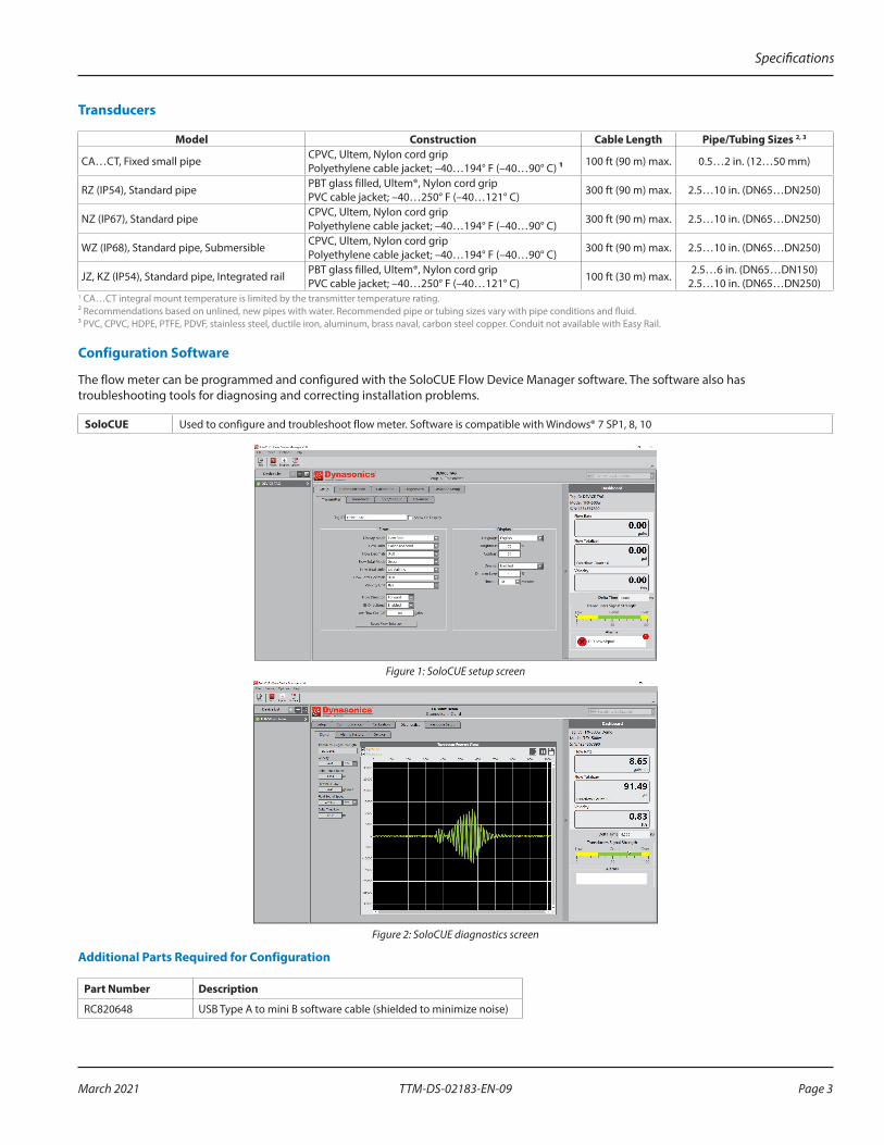
The flow meter can be programmed and configured with the SoloCUE Flow Device Manager software. The software also has troubleshooting tools for diagnosing and correcting installation problems.
SoloCUE Used to configure and troubleshoot flow meter. Software is compatible with Windows® 7 SP1, 8, 10
Figure 1: SoloCUE setup screen
Figure 2: SoloCUE diagnostics screen
Additional Parts Required for Configuration
Part Number Description
RC820648 USB Type A to mini B software cable (shielded to minimize noise)

Dimensions
Page 4 March 2021TTM-DS-02183-EN-09
DIMENSIONS
TFX-500w Meter
Enclosure, Integral and Remote, Front View Integral Enclosure Side View Remote Enclosure Side View6.00 in.
(152.40 mm)
5.55 in.(140.97 mm)
0.65 in.(16.51 mm)
2.68 in.(68.07)
0.31 in.(7.87 mm)
2.68 in.(68.07)
0.38 in.(9.65 mm)
Transducers
Remote System with Standard Pipes
NZ/RZ/WZ (W, V or Z mount)RZ (optional alignment rail) NZ/WZ
TOP VIEWOF PIPE
D
A
B
C (Min Clearance)
TOP VIEWOF PIPE
D
Model A B C DRZ 3.75 in. (95.25 mm) 2.35 in. (59.69 mm) — 2.19 in. (55.63 mm)
NZ, WZ 2.95 in. (74.93 mm) 2.75 in. (69.8 mm) 3.00 in. (76.2 mm) 1.70 in. (43.2 mm)Easy Rail JZ/KZ (W or V mount)
F
A
B
C
E
D
inch
mm
Model A B C D E FJZ 13.62 in. (345.95 mm) 11.73 in. (297.94 mm) 0.75 in. (19.05 mm) 0.79 in. (20.06 mm) 2.76 in. (70.10 mm) 2.36 in. (59.94 mm)KZ 19.92 in. (505.97 mm) 18.03 in. (457.96 mm) 0.75 in. (19.05 mm) 0.79 in. (20.06 mm) 2.76 in. (70.10 mm) 2.36 in. (59.94 mm)

Dimensions
Page 5 March 2021 TTM-DS-02183-EN-09
Remote System with Small Pipes
CA…CT
CA…CT (except CF and CL) Pipes and Tubing
1/2…2 in.
CF and CL U-Bolt Connections ANSI Pipe and Copper Tubing
2 in. Models
B
A
D
C
BD
A C
Integral System
CA…CT
CA…CT (except CF and CL) CF and CL U-Bolt Connections
Pipe Size
Pipe Material A B C D
1/2 in.
ANSI/DN 2.46 in. (62.48 mm) 2.36 in. (59.94 mm) 2.66 in. (67.56 mm) 0.84 in. (21.34 mm)
Copper 2.46 in. (62.48 mm) 2.36 in. (59.94 mm) 3.33 in. (84.58 mm) 0.63 in. (16.00 mm)
Tubing 2.46 in. (62.48 mm) 2.28 in. (57.91 mm) 3.72 in. (94.49 mm) 0.50 in. (12.70 mm)
3/4 in.
ANSI/DN 2.46 in. (62.48 mm) 2.57 in. (65.28 mm) 2.66 in. (67.56 mm) 1.05 in. (26.67 mm)
Copper 2.46 in. (62.48 mm) 2.50 in. (63.50 mm) 3.56 in. (90.42 mm) 0.88 in. (22.35 mm)
Tubing 2.46 in. (62.48 mm) 2.50 in. (63.50 mm) 3.56 in. (90.42 mm) 0.75 in. (19.05 mm)
1 in.
ANSI/DN 2.46 in. (62.48 mm) 2.92 in. (74.17 mm) 2.86 in. (72.64 mm) 1.32 in. (33.53 mm)
Copper 2.46 in. (62.48 mm) 2.87 in. (72.90 mm) 3.80 in. (96.52 mm) 1.13 in. (28.70 mm)
Tubing 2.46 in. (62.48 mm) 2.75 in. (69.85 mm) 3.80 in. (96.52 mm) 1.00 in. (25.40 mm)
1-1/4 in.
ANSI/DN 2.80 in. (71.12 mm) 3.18 in. (80.77 mm) 3.14 in. (79.76 mm) 1.66 in. (42.16 mm)
Copper 2.46 in. (62.48 mm) 3.00 in. (76.20 mm) 4.04 in. (102.62 mm) 1.38 in. (35.05 mm)
Tubing 2.46 in. (62.48 mm) 3.00 in. (76.20 mm) 4.04 in. (102.62 mm) 1.25 in. (31.75 mm)
1-1/2 in.
ANSI/DN 3.02 in. (76.71 mm) 3.40 in. (86.36 mm) 3.33 in. (84.58 mm) 1.90 in. (48.26 mm)
Copper 2.71 in. (68.83 mm) 2.86 in. (72.64 mm) 4.28 in. (108.71 mm) 1.63 in. (41.40 mm)
Tubing 2.71 in. (68.83 mm) 3.31 in. (84.07 mm) 4.28 in. (108.71 mm) 1.50 in. (38.10 mm)
2 in.
ANSI/DN 3.70 in. (93.98 mm) 3.42 in. (86.87 mm)* 5.50 in. (139.70 mm) 2.38 in. (60.45 mm)*
Copper 3.70 in. (93.98 mm) 3.38 in. (85.85 mm)* 5.50 in. (139.70 mm) 2.13 in. (54.10 mm)*
Tubing 3.21 in. (81.53 mm) 3.85 in. (97.79 mm) 4.75 in. (120.65 mm) 2.00 in. (50.80 mm)
* Varies due to U-bolt configuration
Part Number Construction
Page 6 March 2021TTM-DS-02183-EN-09
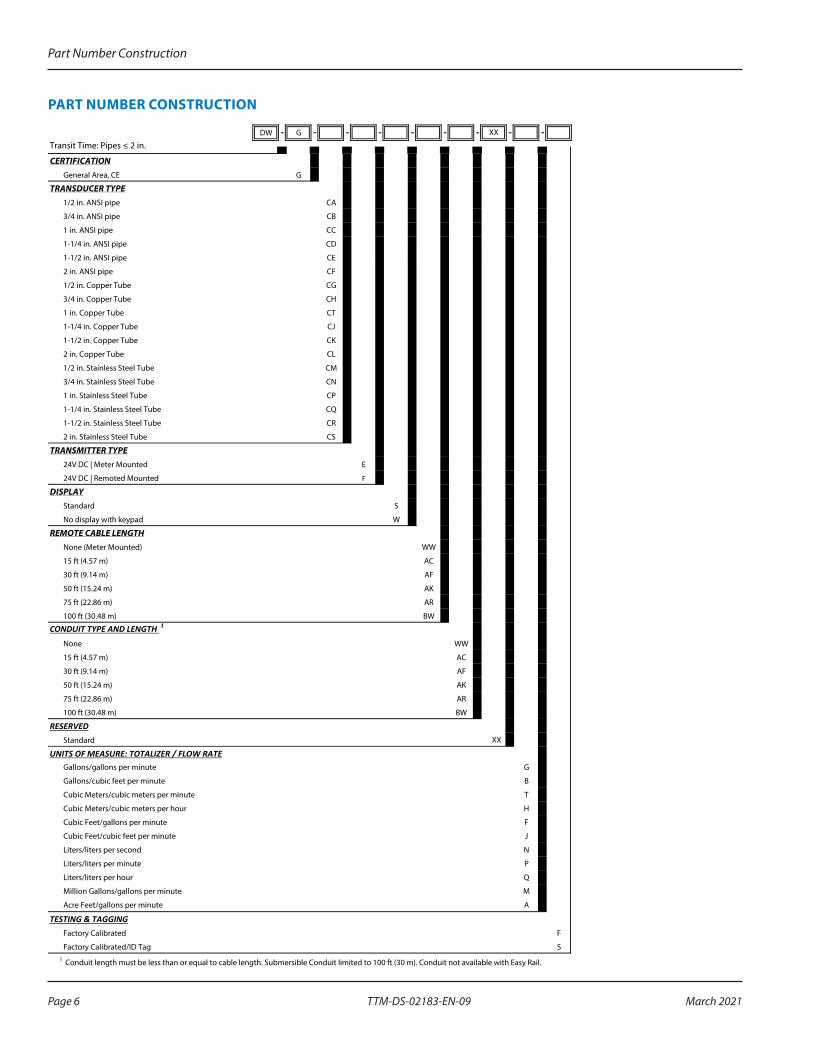
PART NUMBER CONSTRUCTION
DW - G - - - - - - - -
CERTIFICATIONGeneral Area, CE G
TRANSDUCER TYPE1/2 in. ANSI pipe CA
3/4 in. ANSI pipe CB
1 in. ANSI pipe CC
1-1/4 in. ANSI pipe CD
1-1/2 in. ANSI pipe CE
2 in. ANSI pipe CF
1/2 in. Copper Tube CG
3/4 in. Copper Tube CH
1 in. Copper Tube CT
1-1/4 in. Copper Tube CJ
1-1/2 in. Copper Tube CK
2 in. Copper Tube CL
1/2 in. Stainless Steel Tube CM
3/4 in. Stainless Steel Tube CN
1 in. Stainless Steel Tube CP
1-1/4 in. Stainless Steel Tube CQ
1-1/2 in. Stainless Steel Tube CR
2 in. Stainless Steel Tube CS
TRANSMITTER TYPE24V DC | Meter Mounted E
24V DC | Remoted Mounted F
DISPLAYStandard S
No display with keypad W
REMOTE CABLE LENGTHNone (Meter Mounted) WW
15 ft (4.57 m) AC
30 ft (9.14 m) AF
50 ft (15.24 m) AK
75 ft (22.86 m) AR
100 ft (30.48 m) BW
CONDUIT TYPE AND LENGTH 1
None WW
15 ft (4.57 m) AC
30 ft (9.14 m) AF
50 ft (15.24 m) AK
75 ft (22.86 m) AR
100 ft (30.48 m) BW
RESERVEDStandard XX
UNITS OF MEASURE: TOTALIZER / FLOW RATEGallons/gallons per minute G
Gallons/cubic feet per minute B
Cubic Meters/cubic meters per minute T
Cubic Meters/cubic meters per hour H
Cubic Feet/gallons per minute F
Cubic Feet/cubic feet per minute J
Liters/liters per second N
Liters/liters per minute P
Liters/liters per hour Q
Million Gallons/gallons per minute M
Acre Feet/gallons per minute A
TESTING & TAGGINGFactory Calibrated F
Factory Calibrated/ID Tag S1 Conduit length must be less than or equal to cable length. Submersible Conduit limited to 100 ft (30 m). Conduit not available with Easy Rail.
Transit Time: Pipes ≤ 2 in. XX

Part Number Construction
Page 7 March 2021 TTM-DS-02183-EN-09
DW - G - - F - - - - - -
CERTIFICATIONSGeneral Area, CE G
TRANSDUCER TYPEJZ
KZ
NZ
WZ
Easy Rail | 2.5…6 in. (65…150 mm) Pipes
Easy Rail | 2.5…10 in. (65…250 mm) Pipes
DTTN | 2.5…10 in. (65…250 mm) Pipes
DTTN (Submersible) | 2.5…10 in. (65…250 mm) Pipes
DTTR | 2.5…10 in. (65…250 mm) Pipes RZ
TRANSMITTER TYPE24V DC Remote Mounted F
DISPLAYStandard S
No display with keypad W
REMOTE CABLE LENGTH15 ft (4.57 m) AC
30 ft (9.14 m) AF
50 ft (15.24 m) AK
75 ft (22.86 m) AR
100 ft (30.48 m) BW
150 ft (45.72 m) BK
200 ft (60.96 m) DW
250 ft (76.20 m) DK
300 ft (91.44 m) EW
CONDUIT AND CABLE LENGTH 1
None WW
15 ft (4.57 m) AC
30 ft (9.14 m) AF
50 ft (15.24 m) AK
75 ft (22.86 m) AR
100 ft (30.48 m) BW
150 ft (45.72 m) BK
200 ft (60.96 m) DW
250 ft (76.20 m) DK
300 ft (91.44 m) EW
RESERVEDStandard XX
UNITS OF MEASURE: TOTALIZER / FLOW RATEGallons/gallons per minute GGallons/cubic feet per minute BCubic Meters/cubic meters per minute TCubic Meters/cubic meters per hour HCubic Feet/gallons per minute FCubic Feet/cubic feet per minute JLiters/liters per second N
Liters/liters per minute P
Liters/liters per hour Q
Million Gallons/gallons per minute M
Acre Feet/gallons per minute A
TESTING & TAGGINGFactory Calibrated FFactory Calibrated/ID Tag S
1 Conduit length must be less than or equal to cable length. Submersible Conduit limited to 100 ft (30 m). Conduit not available with Easy Rail.
Transit Time: Pipes > 2 in.XX

Transit Time Ultrasonic Flow Meters, TFX-500w Clamp-On Meter
www.badgermeter.com
Dynasonics is a registered trademark of Badger Meter, Inc. Other trademarks appearing in this document are the property of their respective entities. Due to continuous research, product improvements and enhancements, Badger Meter reserves the right to change product or system specifications without notice, except to the extent an outstanding contractual obligation exists. © 2021 Badger Meter, Inc. All rights reserved.
Control. Manage. Optimize.
PARTS AND ACCESSORIES
Couplant
Part Number DescriptionD002-2011-001 Dow Corning® Molykote® 111 Grease; 5.3 oz Tube; 150° F (65° C) D002-2011-002 Dow Corning 732; Permanent Mount; 356° F (180° C)
Dow 111 grease is included with transducers.
Power Supplies
Part Number Description68334-001 Wall Plug; 100…264V AC In; 24V DC Out; -20…50° C 68334-002 Module; 85…264V AC In; 24V DC Out; -30…70° C
For ordering transducers and transmitter separately, please contact factory.