Special University Course for Future Engineers Lecture...
332
MODULE 1 ‐ 4 WEEKS REFRIGERATION & AIR CONDITIONING INDUSTRY, EVOLUTION OF REFRIGERANTS & ENVIRONMENTAL IMPACTS MODULE 2 ‐ 3.5 WEEKS ALTERNATIVE REFRIGERANTS FOR DIFFERENT SECTORS & LUBRICANTS MODULE 3 ‐ 3 WEEKS CONTAINMENT OF REFRIGERANTS, SERVICE & MAINTENANCE OF AIR CONDITIONING & REFRIGERATION SYSTEMS MODULE 4 ‐ 2 WEEKS SAFE USE & HANDLING OF REFRIGERANTS MODULE 5 ‐ 2 WEEKS RELATED STANDARDS AND CODES OF SYSTEMS AND SUBSTANCES Refrigerant Management Special University Course for Future Engineers Lecture Notes Reference materials for teachers/instructors
-
Upload
nguyenthuy -
Category
Documents
-
view
214 -
download
0
Transcript of Special University Course for Future Engineers Lecture...

MODULE 1 ‐ 4 WEEKS
REFRIGERATION & AIR CONDITIONING INDUSTRY, EVOLUTION OF REFRIGERANTS &
ENVIRONMENTAL IMPACTS
MODULE 2 ‐ 3.5 WEEKS
ALTERNATIVE REFRIGERANTS FOR DIFFERENT SECTORS & LUBRICANTS
MODULE 3 ‐ 3 WEEKS
CONTAINMENT OF REFRIGERANTS, SERVICE & MAINTENANCE OF AIR CONDITIONING &
REFRIGERATION SYSTEMS
MODULE 4 ‐ 2 WEEKS
SAFE USE & HANDLING OF REFRIGERANTS
MODULE 5 ‐ 2 WEEKS
RELATED STANDARDS AND CODES OF SYSTEMS AND SUBSTANCES
Refrigerant Management
Special University Course for Future Engineers
Lecture NotesReference materials for teachers/instructors

MODULE 1 NOTES: REFRIGERATION AND AIR CONDITIONING INDUSTRY, EVOLUTION OF REFRIGERANTS AND ENVIRONMENTAL IMPACTS . 1
MODULE 1. NOTES 4 WEEKS
REFRIGERATION AND AIR CONDITIONING
INDUSTRY, EVOLUTION OF REFRIGERANTS
AND ENVIRONMENTAL IMPACTS

MODULE 1 NOTES: REFRIGERATION AND AIR CONDITIONING INDUSTRY, EVOLUTION OF REFRIGERANTS AND ENVIRONMENTAL IMPACTS . 2
1. INTRODUCTION:
Getting introduced to the air conditioning industry is a major issue, since air conditioning industry
interacts in almost every application in our life. AC system employs the refrigeration cycle to achieve
cooling or heating and ODS is about the type of refrigerants used in the refrigeration cycle. From then
on, reference to harmful gases from AC system will be clearly understood to imply the refrigerant in the
refrigeration system that drives the AC system. Gases that are released from AC system into the
atmosphere due to leaks and wrong maintenance practices that have been considered toxic result in
many environmental complications, dealing with these gases (refrigerants) is considered essential. In this
module, we will get introduced to the air conditioning systems, the refrigerants used, and their effects
on the environment in respect to global warming and ozone depletion, in addition to the treaties that
evolved to control their usage.
2. REFRIGERATION INDUSTRY: HISTORY AND TIMELINE (References: allchemi.com,
http://pomo.cca.edu/~mwong3/interactivefuture/history/index.html, http://www.history‐
magazine.com/refrig.html, 123helpme.com, http://www.geckoair.com.au/refrigeration.html)
In prehistoric times, man found that his food would last longer during times when food was not
available if stored in the coolness of a cave or packed in snow.
In China, before the first millennium, ice was harvested and stored.
Hebrews, Greeks, and Romans placed large amounts of snow into storage pits dug into the
ground and insulated with wood and straw.
The ancient Egyptians filled earthen jars with boiled water and put them on their roofs, thus
exposing the jars to the night’s cool air.
In India, evaporative cooling was employed. When a liquid vaporizes rapidly, it expands quickly.
Kinetic energy increases, and this increase is drawn from the immediate surroundings of the
vapor. These surroundings are therefore cooled.

MODULE 1 NOTES: REFRIGERATION AND AIR CONDITIONING INDUSTRY, EVOLUTION OF REFRIGERANTS AND ENVIRONMENTAL IMPACTS . 3
The intermediate stage in the history of cooling foods was to add chemicals like sodium nitrate
or potassium nitrate to water causing the temperature to fall. Cooling drinks via this method was
recorded in 1550, as were the words "to refrigerate”.
In 1600 in France, people rotated long‐necked bottles in water in which saltpeter had been
dissolved. This solution could be used to produce very low temperatures and to make ice.
In mid 1800s, Frederick Tudor, from New England, who became known as the “Ice King”, focused
on shipping ice to tropical climates. He experimented with insulating materials and built
icehouses that decreased melting losses from 66 % to less than 8 %.
In 1841, the American physician John Gorrie, devised an air‐conditioning system for a ward in a
Florida hospital for treating yellow‐fever patients by blowing air over buckets of ice.
John Gorrie, gave up his medical practice to engage in time‐consuming experimentation with ice
making. He was granted the first U.S. patent for mechanical refrigeration in 1851. His basic
principle – that of compressing a gas, cooling it by sending it through radiating coils, and then
expanding it to lower the temperature further – is the one most often used in refrigerators today.
Shortly afterward, an Australian, James Harrison, examined the refrigerators used by Gorrie and
introduced vapor‐compression refrigeration to the brewing and meatpacking industries.
In 1859, Ferdinand Carré of France developed a somewhat more complex system. Unlike earlier
compression‐compression machines, which used air as a coolant, Carré's equipment contained
rapidly expanding ammonia. (Ammonia liquefies at a much lower temperature than water and
is thus able to absorb more heat.) Carré's refrigerators were widely used, and vapor compression
refrigeration became, and still is, the most widely used method of cooling.
However, the cost, size, and complexity of refrigeration systems of the time, coupled with the
toxicity of their ammonia coolants, prevented the general use of mechanical refrigerators in the
home. Most households used iceboxes that were supplied almost daily with blocks of ice from a
local refrigeration plant.
Beginning in the 1840s, refrigerated cars were used to transport milk and butter.
By 1860, refrigerated transport was limited to mostly seafood and dairy products.
In 1867, the refrigerated railroad car was patented by J.B. Sutherland of Detroit, Michigan. He
designed an insulated car with ice bunkers at each end. Air came in on the top, passed through
the bunkers, and circulated through the car by gravity, controlled by the use of hanging flaps that
created differences in air temperature.
In 1867, the first refrigerated car to carry fresh fruit was built by Parker Earle of Illinois, who
shipped strawberries on the Illinois Central Railroad. Each chest contained 100 pounds of ice and
200 quarts of strawberries.

MODULE 1 NOTES: REFRIGERATION AND AIR CONDITIONING INDUSTRY, EVOLUTION OF REFRIGERANTS AND ENVIRONMENTAL IMPACTS . 4
Natural ice supply became an industry unto itself. More companies entered the business, prices
decreased, and refrigeration using ice became more accessible. By 1879, there were 35
commercial ice plants in America, more than 200 a decade later, and 2,000 by 1909.
However, as time went on, ice, as a refrigeration agent, became a health problem because of
pollution and sewage dumping in lakes and ponds.
In 1873, the European Karl Von Linde patented the first commercial mechanical refrigeration
system based on Ammonia. This permitted /year round production of ice.
The household refrigerator was introduced in the early 1920s. The Frigidaire company – then a
subsidiary of General Motors – was the leading manufacturer of household refrigerators. Their
M‐9 refrigerator was the most advanced model of its time. With a steel cabinet, air cooled
compressor and direct cooling coils, it had a net weight of 170 kg and sold for $468.
By then, a variety of refrigerants were used including ammonia, sulfur dioxide, methyl chloride,
ethyl chloride, isobutene, ethylene, methylene chloride and carbon
Many other industries found refrigeration a boon to their business. In metalworking, for instance,
mechanically produced cold helped temper cutlery and tools. Iron production got a boost, as
refrigeration removed moisture from the air delivered to blast furnaces, increasing production.
Textile mills used refrigeration in mercerizing, bleaching, and dyeing. Oil refineries found it
essential, as did the manufacturers of paper, drugs, soap, glue, shoe polish, perfume, celluloid,
and photographic materials. Fur and woolen goods storage could beat the moths by using
refrigerated warehouses. Refrigeration also helped nurseries and florists, especially to meet
seasonal needs since cut flowers could last longer. Moreover, there was the morbid application
of preserving human bodies. Hospitality businesses including hotels, restaurants, saloons, and
soda fountains, proved to be big markets for ice.
Despite the inherent advantages, refrigeration had its problems. Refrigerants like sulfur dioxide
and methyl chloride were causing people to die. Ammonia had an equally serious toxic effect if
it leaked.
In the 1920s, a number of synthetic refrigerants called chlorofluorocarbons or CFCs were
developed by Tom Midgley, a researcher at Frigidaire. They met four critical criteria – they had
an appropriate boiling point, non‐poisonous, nonflammable and had a distinct, but not
unpleasant odor. The best known of these substances was patented under the brand name of
Freon.
In 1973, Prof. James Lovelock reported finding trace amounts of refrigerant gases in the
atmosphere.

MODULE 1 NOTES: REFRIGERATION AND AIR CONDITIONING INDUSTRY, EVOLUTION OF REFRIGERANTS AND ENVIRONMENTAL IMPACTS . 5
In 1974, Sherwood Rowland and Mario Molina predicted that chlorofluorocarbon refrigerant
gases would reach the high stratosphere and there damage the protective ozone layer.
In 1985 the "ozone hole" over the Antarctic had been discovered and by 1990 Rowland and
Molina's prediction was proved correct.
3. BASICS OF VAPOR COMPRESSION CYCLE
The five commercially available refrigeration cycles are: Vapor compression, Absorption, Gas cycle,
Steam jet and Thermoelectric, of which the most popular is the vapor compression cycle.
The basic refrigeration cycle is similar for many refrigeration and air‐conditioning applications. All four
components (compressor, condenser, expansion valve and evaporator) are steady flow devices. The
kinetic and potential energy changes of the refrigerant are usually small compared to the work and heat
transfer, and are therefore neglected.
a. Components and Type of Compressors: (http://ffden2.phys.uaf.edu/212_spring2007)
In this stage, the refrigerant enters the compressor as a gas under low pressure and having a low
temperature. Then, the refrigerant is compressed adiabatically, so the fluid leaves the compressor under
high pressure and with a high temperature and high velocity.
Types of Compressors: (References: http://www.powershow.com/view4/5f8fcc‐
NzI1O/Chapter_No_3_powerpoint_ppt_presentation,
http://www.slideshare.net/tatya922050/compressor‐and‐compressedairsystems1,
engineeringtoolbox.com, http://www.aspsoklahoma.com/products/centrifugal‐air‐compressor/,
http://www.aircentersofflorida.com/products/centrifugal‐air‐compressor, Wikipedia.org,
http://www.slideshare.net/saurabhtholia/compressor‐and‐compressed‐air‐systems,
http://www.foodtechinfo.com/FoodPro/Efficiency/air_compressor_tutorial.htm)
Centrifugal Compressors: The centrifugal air compressor is a dynamic compressor, which depends on
transfer of energy from a rotating impeller to the air. The rotor accomplishes this by changing the
momentum and pressure of the air. This momentum is converted to useful pressure by slowing the air
down in a stationary diffuser. The centrifugal air compressor is an oil free compressor by design. The oil
lubricated running gear is separated from the air by shaft seals and atmospheric vents. The centrifugal is
a continuous duty compressor, with few moving parts, that is particularly suited to high volume
applications‐especially where oil free air is required. Centrifugal air compressors are water‐cooled and
may be packaged; typically the package includes the after‐cooler and all controls. These compressors

MODULE 1 NOTES: REFRIGERATION AND AIR CONDITIONING INDUSTRY, EVOLUTION OF REFRIGERANTS AND ENVIRONMENTAL IMPACTS . 6
have appreciably different characteristics as compared to reciprocating machines. A small change in
compression ratio produces a marked change in compressor output and efficiency. Centrifugal machines
are better suited for applications requiring very high capacities, typically above 12,000 cooling units
BTUH.
Reciprocating Compressors: In industry, reciprocating compressors are the most widely used type for
both air and refrigerant compression. They work on the principles of a bicycle pump and are
characterized by a flow output that remains nearly constant over a range of discharge pressures. Also,
the compressor capacity is directly proportional to the speed. The output, however, is a pulsating one.
Reciprocating compressors are available in many configurations. The four most widely used are
horizontal, vertical, horizontal balance‐opposed and tandem. The reciprocating air compressor is
considered single acting when the compressing is accomplished using only one side of the piston. A
compressor using both sides of the piston is considered double acting.
Screw Compressors: Screw: has two screw (screw‐shaped) rotors, one male and the other female. It
consists of two screws ‐ one with convex and the other with concave contour mostly called male and
female rotor respectively. These two screws get rotating by means of gear trips there by sucking the air
through an inlet port in chamber and then compressing the same. The helix of the male and female rotor
screw is designed to permit complete charging of the inter lobe space before the re‐mesh. On completion
of the filling operation the inlet end of male and female lobes begins to re‐engage thus reduces the
volume of air continuously. The helix screws are designed to permit complete charging of the inter lobe
space before the re‐mesh. On completion of the filling operation the screws begin to re‐engage thus
reduces the volume of air continuously.

MODULE 1 NOTES: REFRIGERATION AND AIR CONDITIONING INDUSTRY, EVOLUTION OF REFRIGERANTS AND ENVIRONMENTAL IMPACTS . 7
Scroll Compressors: Has two spiral‐shaped parts (scrolls). One of the scrolls is fixed, while the other
orbits eccentrically without rotating. Fluid is then trapped and pumped or compressing pockets of fluid
between the scrolls. Another method for producing the compression motion is co‐rotating the scrolls, in
synchronous motion, but with offset centers of rotation. The relative motion is the same as if one were
orbiting. Rotary compressors have rotors in place of pistons and give a continuous pulsation free
discharge. They operate at high speed and generally provide higher throughput than reciprocating
compressors. Their capital costs are low, they are compact in size, have low weight, and are easy to
maintain. For this reason they have gained popularity with industry. They are most commonly used in
sizes from about 30 to 200 hp or 22 to 150 kW. Types of rotary compressors include: Lobe compressor,
Screw compressor, Rotary vane / sliding‐vane. The picture shows a screw compressor. Rotary screw
compressors may be air or water‐cooled. Since the cooling takes place right inside the compressor, the
working parts never experience extreme operating temperatures. The rotary compressor, therefore, is a
continuous duty, air cooled or water cooled compressor package.
Hermetic Compressors: Compressors used in refrigeration systems are often described as hermetic to
describe how the compressor and motor drive are situated in relation to the gas or vapor being
compressed. The compressor and its driving motor are integrated, and operate within the pressurized
gas envelope of the system. The motor is designed to operate in, and be cooled by, the refrigerant gas
being compressed. They use a one‐piece welded steel casing that cannot be opened for repair; if the
hermetic fails it is simply replaced with an entire new unit. Advantages: there is no route for the gas to
leak out of the system. Disadvantages: the motor drive cannot be repaired or maintained, and the entire
compressor must be removed if a motor fails and the burnt‐out windings can contaminate whole
systems, thereby requiring the system to be entirely pumped down and the gas replaced. Uses: Hermetic
compressors are used in low‐cost factory‐assembled consumer goods where the cost of repair is high
compared to the value of the device, and it would be more economical to just purchase a new device

MODULE 1 NOTES: REFRIGERATION AND AIR CONDITIONING INDUSTRY, EVOLUTION OF REFRIGERANTS AND ENVIRONMENTAL IMPACTS . 8
2. Condenser: The refrigerant with high pressure, high temperature gas releases heat energy and
condenses inside the "condenser" portion of the system. The condenser is in contact with the hot
reservoir of the refrigeration system. (The gas releases heat into the hot reservoir because of the external
work added to the gas.) The refrigerant leaves as a high pressure, high temperature liquid.
3. Throttling (Expansion) Valve: The liquid refrigerant is pushed through a throttling valve, which
causes it to expand. As a result, the refrigerant now has low pressure and lower temperature, while still
in the mixed phase. (The throttling valve can be either a thin slit or some sort of plug with holes in it.
When the refrigerant is forced through the throttle, its pressure is reduced, causing the liquid to expand.)
4. Evaporator: The low pressure, low temperature refrigerant enters the evaporator, which is in contact
with the cold reservoir. Because a low pressure is maintained, the refrigerant is able to boil at a low
temperature. So, the liquid absorbs heat from the cold reservoir and evaporates. The refrigerant leaves
the evaporator as a low temperature, low pressure gas and is taken into the compressor again, back at
the beginning of the cycle.

MODULE 1 NOTES: REFRIGERATION AND AIR CONDITIONING INDUSTRY, EVOLUTION OF REFRIGERANTS AND ENVIRONMENTAL IMPACTS . 9
Coefficient of Performance (COP)
The efficiency of a refrigeration cycle is expressed in terms of the coefficient of performance (COP).
The objective of the refrigerator is to remove heat (QL) from the refrigerated medium. To accomplish
this objective, it requires a work input of Wcomp,in.
12, hhmW refincomp and 41 hhmQ refL
The COP of a refrigeration cycle is hence expressed as:
12
41
,Input Required
Output Desired
hh
hh
w
qCOP
incomp
L
The term “h” in the COP formula represents the enthalpy which is the measure of energy in a
thermodynamic system. It includes the internal energy, which is the energy required to create a system,
and the amount of energy required to make room for it by displacing its environment and establishing its
volume and pressure in kJ/kg (SI unit) or BTU/lbm (IP unit).
Enthalpy values can be obtained from the refrigerant properties tables or from the Ph‐charts.
4. REFRIGERANTS
a. Definition:
A chemical used in cooling systems for mechanical devices such as refrigerators and air conditioners. It
can readily absorb heat at one temperature, and then compressed by a heat pump to a higher
temperature and pressure where it changes phase and discharges the absorbed heat.
b. Evolution and History of Refrigerants (Ref.: ASHRAE 2005, Denison 1996,Downing 1988,
Wikipedia, 2006)

MODULE 1 NOTES: REFRIGERATION AND AIR CONDITIONING INDUSTRY, EVOLUTION OF REFRIGERANTS AND ENVIRONMENTAL IMPACTS . 10
Since the midst of 18th and till the beginning of 20th centuries, a number of substances have been
used as refrigerants for refrigerating systems: water, diethyl and methyl ethers, ammonia,
carbon dioxide, sulfur dioxide and sulfur anhydride, methyl chloride, etc...
In 1755, water became the first refrigerant. It was used this way in the laboratory facility created
by William Hallen.
In 1834, Jacob Perkins manufactured a compression machine operating on diethyl ether.
In 1844, John Gorrie manufactured an air‐compression‐and‐extension machine.
In 1859, Ferdinand Carré created an ammonia/water absorption refrigerating machine.
In 1863, Charles Teller tested a compressor operating on methyl ether.
In 1873, ammonia was first used in vapor compression systems
In 1875, sulfur dioxide and methyl ether were first used in vapor compression systems
In 1878, methyl chloride was first used in vapor compression systems.
Until the end of the 20th century, sulphur anhydride and ammonia have been widely used as
refrigerants. Other refrigerants, such as ethers, acetone and alcohols were discarded after a few
tests.
In 1926, the superior properties of R‐11 were discovered and it was adopted by Carrier.
In 1928, Thomas Midgley and his collaborators, Albert Henne and Robert McNary, employed by
Frigidaire Division of General Motors, had identified and synthesized CFC refrigerants such as
dichlorodifluoromethane, now known as R‐12.
To demonstrate the safety of the new compounds, at a meeting of the American Chemical
Society, Midgley inhaled R‐12 and blew out a candle with it. While this demonstration was
dramatic, it would be a clear violation of safe handling practices today.
After the output of the first batches of dichlorodifluoromethane related to the group of
chlorofluorocarbons (CFCs) by the company "Kinetic Chemicals Inc", (USA), and organization of
its industrial production in 1932, many working substances, except ammonia, almost completely
disappeared from the market of refrigerants.
The same company introduced the commercial name of freon‐12.
In the midst of the 1930s there was adjusted production of R11, R113 and R114 refrigerants on an
industrial scale. R11 refrigerant was further used in the air‐conditioning systems.
Since 1935, there has been organized production of R22 refrigerant related to the group of
hydrochlorofluorocarbons (HCFC). R22 was used in low‐temperature refrigerating systems.
In 1936, Albert Henne, co‐inventor of the CFCs refrigerants, synthesized R‐134a.
In 1952, R502 was developed, substituting R22 in low‐temperature refrigerating facilities, which
allowed reducing discharge temperature characteristic for R22 in compressors. In order to obtain
very low temperatures, R13, R503 and R13B1 refrigerants were derived.
In the 1960s, refrigerants have become main refrigerants in industrial and commercial mid‐ and
low‐temperature refrigerating facilities, conditioners and heat pumps.
By the midst of the 1970s, the output of freons has reached very high figures.
By 1976, the output of R12 had reached almost 340,000 tons and 27,000 tons of this was intended
for refrigerating systems.
By the end of the 1970s, CFCs and HCFCs became the lead refrigerants in refrigerating industry
(domestic, commercial and industrial refrigerating equipment). They were viewed as the
substances possessing better properties compared with other refrigerants.

MODULE 1 NOTES: REFRIGERATION AND AIR CONDITIONING INDUSTRY, EVOLUTION OF REFRIGERANTS AND ENVIRONMENTAL IMPACTS . 11
Out of all refrigerants suggested before, only ammonia (R717) with its highest thermodynamic
and technical‐operational figures within the wide temperature range, compared with
refrigerants of CFC and HCFC groups was being widely used in industrial refrigerating systems,
heat pumps, absorption conditioners and domestic absorption refrigerators.
However, by the 1980s, CFCs and HCFCs had become a matter of concern due to existing global
problems: increasing greenhouse effect and possible destruction of ozone layer.
In 1986, overall production of freons amounted 1.123 million tons (of this 30% was the share of
the USA, 20% ‐ of Europe, 10 % ‐ of Russia and Japan each).
In 1985, the problem of control of ODS was put on an international agenda at the Vienna
Convention on Protection of Ozone Layer.
In 1987, a further important step in the solution of this problem became the Montreal Protocol
having been signed by all industrial countries.
By the beginning of the 1990s, main world producers of chemical products had developed and
produced one‐component ozone‐safe R134a refrigerant and alternative service (interstage)
blends (R401A, etc.) with the aim of substituting R12.
Prohibition on R12 resulted in an increase of R22 production and sale; in 1994 it amounted
207,515 tons.
Although CFCs have been substantially displaced from domestic refrigerating equipment,
transport refrigerating facilities, commercial refrigerating equipment, and industrial
conditioners. However in the countries of European Union up to 110,000 tons of CFCs are still
used in operating refrigerating equipment.
In order to substitute R502 and R22, service blends related to HCFC group (R402A, etc.), and
ozone‐safe blends of CFC group (R407C, etc.) were created. However, by now neither of well‐
known or recently synthesized individual refrigerants possess complete characteristics peculiar
to CFCs and CFCs refrigerants.
During the recent years refrigerating industry has been actively looking for substitution of HCFC
group of refrigerants.
In 1997, the Kyoto Protocol on Climate Change, aimed at reducing greenhouse gases emissions
complicated the selection of a long‐term alternative to R22 even more.
In order to investigate and develop alternative refrigerants to substitute R22 refrigerant (HCFCs),
Alternative Refrigerants Evaluation Program, (AREP) has been organized. 40 biggest companies
from all over the world participate in this program.
A number of states invested considerable financial means into development of alternative
refrigerants that amounted to more than $2.4 billion during 2000‐2005. The expenses on the
investigation of R134a toxicity alone amounted to $4.5 million, with the duration of investigation
of 7 years.
c. Refrigerants Generations: (References: Calm, 1997; Calm, 2012)
The historic progression of refrigerants encompasses four phases based on defining selection criteria:
First generation – whatever worked
MODULE 1 NOTES: REFRIGERATION AND AIR CONDITIONING INDUSTRY, EVOLUTION OF REFRIGERANTS AND ENVIRONMENTAL IMPACTS . 12
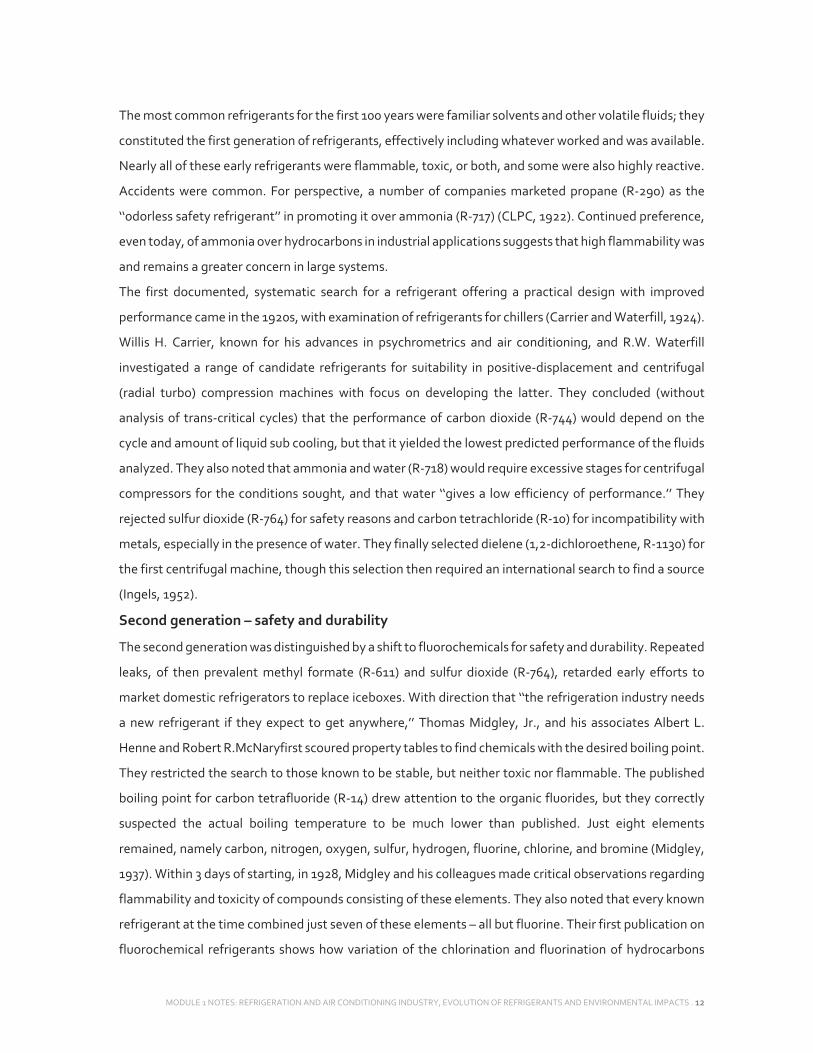
The most common refrigerants for the first 100 years were familiar solvents and other volatile fluids; they
constituted the first generation of refrigerants, effectively including whatever worked and was available.
Nearly all of these early refrigerants were flammable, toxic, or both, and some were also highly reactive.
Accidents were common. For perspective, a number of companies marketed propane (R‐290) as the
‘‘odorless safety refrigerant’’ in promoting it over ammonia (R‐717) (CLPC, 1922). Continued preference,
even today, of ammonia over hydrocarbons in industrial applications suggests that high flammability was
and remains a greater concern in large systems.
The first documented, systematic search for a refrigerant offering a practical design with improved
performance came in the 1920s, with examination of refrigerants for chillers (Carrier and Waterfill, 1924).
Willis H. Carrier, known for his advances in psychrometrics and air conditioning, and R.W. Waterfill
investigated a range of candidate refrigerants for suitability in positive‐displacement and centrifugal
(radial turbo) compression machines with focus on developing the latter. They concluded (without
analysis of trans‐critical cycles) that the performance of carbon dioxide (R‐744) would depend on the
cycle and amount of liquid sub cooling, but that it yielded the lowest predicted performance of the fluids
analyzed. They also noted that ammonia and water (R‐718) would require excessive stages for centrifugal
compressors for the conditions sought, and that water ‘‘gives a low efficiency of performance.’’ They
rejected sulfur dioxide (R‐764) for safety reasons and carbon tetrachloride (R‐10) for incompatibility with
metals, especially in the presence of water. They finally selected dielene (1,2‐dichloroethene, R‐1130) for
the first centrifugal machine, though this selection then required an international search to find a source
(Ingels, 1952).
Second generation – safety and durability
The second generation was distinguished by a shift to fluorochemicals for safety and durability. Repeated
leaks, of then prevalent methyl formate (R‐611) and sulfur dioxide (R‐764), retarded early efforts to
market domestic refrigerators to replace iceboxes. With direction that ‘‘the refrigeration industry needs
a new refrigerant if they expect to get anywhere,’’ Thomas Midgley, Jr., and his associates Albert L.
Henne and Robert R.McNaryfirst scoured property tables to find chemicals with the desired boiling point.
They restricted the search to those known to be stable, but neither toxic nor flammable. The published
boiling point for carbon tetrafluoride (R‐14) drew attention to the organic fluorides, but they correctly
suspected the actual boiling temperature to be much lower than published. Just eight elements
remained, namely carbon, nitrogen, oxygen, sulfur, hydrogen, fluorine, chlorine, and bromine (Midgley,
1937). Within 3 days of starting, in 1928, Midgley and his colleagues made critical observations regarding
flammability and toxicity of compounds consisting of these elements. They also noted that every known
refrigerant at the time combined just seven of these elements – all but fluorine. Their first publication on
fluorochemical refrigerants shows how variation of the chlorination and fluorination of hydrocarbons

MODULE 1 NOTES: REFRIGERATION AND AIR CONDITIONING INDUSTRY, EVOLUTION OF REFRIGERANTS AND ENVIRONMENTAL IMPACTS . 13
influences the boiling point, flammability, and toxicity (Midgley and Henne, 1930). Commercial
production of R‐12 began in 1931 followed by R‐11 in 1932 (Downing, 1966, 1984). Chlorofluorocarbons
(CFCs) and later – especially starting in the 1950s in residential and small commercial air conditioners and
heat pumps – hydrochlorofluorocarbons (HCFCs) dominated the second generation of refrigerants.
Ammonia continued as, and remains today, the most popular refrigerant in large, industrial systems
especially for food and beverage processing and storage.
Third generation – ozone protection
Linkage of released CFCs – including CFC refrigerants – to depletion of protective ozone catalyzed the
third generation with focus on stratospheric ozone protection. The Vienna Convention and resulting
Montreal Protocol forced abandonment of ozone‐depleting substances (ODSs). Fluorochemicals
retained the primary focus, with emphasis on HCFCs for interim (transitional) use and
hydrofluorocarbons (HFCs) for the longer term. The shifts sparked renewed interest in ‘‘natural
refrigerants’’– particularly ammonia, carbon dioxide, hydrocarbons, and water – along with expanded
use of absorption and other not‐in‐kind (those not using vapor‐compression systems with fluorochemical
refrigerants) approaches. Manufacturers commercialized the first alternative refrigerants in late 1989
and, within 10 years, introduced replacements for most ozone‐depleting refrigerants. Non‐Article 5
(mostly‐developed) countries, sometimes referred to as Article 2 countries, phased out CFC refrigerant
use in new equipment by 1996, as required by the Montreal Protocol (1987). Article 5 countries did so by
2010, and some (for example, China) did earlier. The ‘‘Article 5’’ distinction relates to the level of prior
usage of ozone‐depleting substances as defined in the Protocol. Except as restricted by national
regulations, continued use and service are allowed for existing equipment employing CFC refrigerants
until otherwise retired. The transition from HCFCs also is underway. The Montreal Protocol limits
consumption (defined as production plus imports less exports and specified destruction) of HCFCs in
steps in 1996 (freeze at calculated cap), 2004 (65% of cap), 2010 (25%), 2015 (10%), and 2020 (0.5%) with
full consumption phaseout by 2030 in non‐Article 5 countries (UNEP, 2007a). Individual countries
adopted different response approaches. Most western and central‐European countries accelerated HCFC
phase outs, while the majority of other developed countries set limits by phasing out propellant and
blowing agent (especially R‐ 141b) uses early, requiring phaseout of R‐22 (the most widely used
refrigerant today) by 2010 in new equipment, and then banning all HCFC use in new equipment by 2020.
The schedule for Article 5 countries began with a freeze in 2013 (based on 2009–2010 production and
consumption levels) with declining limits that started in 2015 (90%), 2020 (65%), 2025 (32.5%), and 2030
(2.5%) followed by phaseout in 2040 (UNEP, 2007a). Again, continued future use and service, even after
2040, are allowed for existing equipment employing HCFC refrigerants until otherwise retired except as
restricted by national regulations (Montreal Protocol, 1987; UNEP, 2007a).

MODULE 1 NOTES: REFRIGERATION AND AIR CONDITIONING INDUSTRY, EVOLUTION OF REFRIGERANTS AND ENVIRONMENTAL IMPACTS . 14
Three points warrant notice. First, refrigerants historically constituted only a minor fraction of total ODS
emissions, but most of the same CFCs and some of the HCFCs in common use as refrigerants also were
used in much more emissive applications, including as aerosol propellants, foam blowing agents, and
solvents. Second and at least comparable in importance to the refrigerant replacements, the
environmental concerns prompted major changes in design, manufacturing, installation, service, and
ultimate disposal procedures to reduce avoidable refrigerant emissions (Calm, 2002). Third, the ozone
layer is recovering despite episodic reports of record ozone holes in the Antarctic (WMO, 2006).
Fourth generation – global warming
The very successful response to ozone depletion stands in sharp contrast to the deteriorating situation
with climate change based on Brohan et al. (2006) and Rayner et al. (2006). The Intergovernmental Panel
on Climate Change (IPCC) Fourth Assessment Report (AR4) reflects the latest scientific consensus,
namely that ‘‘warming of the climate system is unequivocal, as is now evident from observations of
increases in global average air and ocean temperatures, widespread melting of snow and ice, and rising
global average sea level’’ (IPCC, 2007). The assessment concluded that ‘‘most of the observed increase in
globally averaged temperatures since the mid‐20th century is very likely due to the observed increase in
anthropogenic greenhouse gas concentrations’’ and that ‘‘discernible human influences now extend to
other aspects of climate, including ocean warming, continental average temperatures, temperature
extremes and wind patterns’’ (IPCC, 2007). The Kyoto Protocol, pursuant to the United Nations
Framework Convention on Climate Change (UNFCCC), sets binding targets for greenhouse gas (GHG)
emissions based on calculated equivalents of carbon dioxide, methane, nitrous oxide, HFCs,
perfluorocarbons (PFCs), and sulfur hexafluoride (Kyoto Protocol, 1997). It does not address ODSs
covered by the Montreal Protocol, although some also are very potent GHGs. National laws and
regulations to implement the Kyoto Protocol differ, but they typically prohibit avoidable releases of HFC
and PFC refrigerants and in some countries also control or tax their use. More recent measures (either
adopted or proposed) at regional, national, state, and municipal levels are more stringent. These
restrictions are forcing shifts to a fourth generation of refrigerants defined by focus on global warming.
The European Parliament set the timing with a directive that bans fluorochemical (‘‘F‐Gas’’) refrigerants
having GWPs exceeding 150 for 100‐yr integration in air conditioners for new model automobiles
effective from 2011 and for all new automobiles starting in 2017 (Horrocks, 2006). The adopted
regulations also require periodic inspection of stationery systems using HFCs (Environment Committee,
2006). The EU Parliament rejected recommended measures that would have banned HFCs as aerosol
propellants by 2006, as foam blowing agents by 2009, and as refrigerants in stationery air conditioners
and refrigeration by 2010. The contentious vote on the last item was 262–368, more than 40% in favor.
This significant support level invites future reconsideration, especially with recent scientific findings

MODULE 1 NOTES: REFRIGERATION AND AIR CONDITIONING INDUSTRY, EVOLUTION OF REFRIGERANTS AND ENVIRONMENTAL IMPACTS . 15
regarding more rapid and more severe onset of climate change. The immediate effect of these measures
is a ban on R‐134a in its largest and, as a refrigerant, its most emissive application –mobile air
conditioners. The adopted GWP limit intentionally allows consideration of low GWP HFCs (notably R‐
152a even though flammable). The F‐Gas measures also sanction more‐stringent national regulations,
some of which prohibit HFCs in large systems, explicitly ban HFC use in chillers, or impose GWP weighted
excise taxes on HFC refrigerants. Unions in Europe are pushing for adoption of more stringent measures
to curb greenhouse gas emissions. A number of states and cities in the USA have proposed restrictions
on GHG emissions, either individually or regionally, though the specific impacts on individual HFCs are
uncertain. A frequent bellwether state and the one with the largest population, California passed new
legislation in late 2006 imposing a first‐in‐the‐nation emissions cap on utilities, refineries, and
manufacturing plants, with a goal of cutting greenhouse gas emissions back to 1990 levels by 2020. The
law requires the state regulatory body to determine actual requirements. The California changes are
likely to impose requirements for low GWP refrigerants in new vehicle systems and prohibit recharging
of leaky systems by unlicensed technicians. Other measures may restrict the HFCs used in commercial
refrigeration systems. At least eight other states are prone to follow California’s lead if it does regulate
HFC uses or emissions. A number of Northeastern and Mid‐Atlantic states joined in a pact in 2007 to
impose caps on power plant emissions and encourage trading of allowances among utilities and the
Governors of five states agreed in 2007 to the Western Regional Climate Action Initiative with similar
goals.
d. Selection, Characteristics and Effect of Refrigerants (Ref.: ASHRAE 2004, ASHRAE 2005, UNEP
1994)

MODULE 1 NOTES: REFRIGERATION AND AIR CONDITIONING INDUSTRY, EVOLUTION OF REFRIGERANTS AND ENVIRONMENTAL IMPACTS . 16
The design of refrigeration equipment depends strongly on the properties of the selected refrigerants.
The ideal refrigerant is noncorrosive and safe and has good thermodynamic properties such as: a boiling
point somewhat below the target temperature, a high heat of vaporization, a moderate density in liquid
form , a relatively high density in gaseous form.
Boiling Point – Latent Heat of Vaporization: The boiling point is the most important physical property
of a refrigerant because it is a direct indicator of the temperature level at which a refrigerant can be used.
On a molar basis, fluids with similar boiling points have almost the same latent heat. Since compressor
displacement is defined on volumetric basis, refrigerants with similar boiling points produce similar
refrigeration effect with a given compressor. On a mass basis, latent heat varies widely among fluids.
Efficiency of a theoretical vapor compression cycle is maximized by fluids with low vapor heat capacity.
This property is associated with fluids having a simple molecular structure and low molecular mass.
Freezing Point: The freezing point of a refrigerant must be lower than any contemplated usage.
Liquid Density: Density is the mass per unit volume. Fluorinated refrigerants are relatively dense. A
dense refrigerant needs a larger liquid line to accommodate the greater flow rate without an increase in
the pressure drop.
Vapor Density: The vapor density of fluorocarbon refrigerants is also relatively heavy. Vapor density
does not matter much in the refrigeration system. The power required in reciprocating and rotary
compressors depend on the number of molecules, not on the weight of the molecules. The power
required in centrifugal compressors, however, depends on the density of the gas since the pressure
developed depends on the velocity and density of the refrigerant. Vapor density is very important outside
the system. When a fluorinated refrigerant is accidentally or intentionally released from the system, it
sinks to the ground and collects in low places. Good ventilation is required near the floor to disperse the
gas.
Temperature/Pressure Relationship: The saturation pressure of a refrigerant is related to its saturation
temperature. As the temperature increases, so does the pressure.
Compression Ratio: Compression ratio is an indication of the amount of work required from the
compressor. A low compression ratio means a high coefficient of performance.
Pressure Drop: The pipes should be as small as possible to reduce the original cost and provide adequate
refrigerant velocity. On the other hand, pipes should be large enough to avoid excessive pressure drop
and friction losses. Pressure drops increase operational costs.

MODULE 1 NOTES: REFRIGERATION AND AIR CONDITIONING INDUSTRY, EVOLUTION OF REFRIGERANTS AND ENVIRONMENTAL IMPACTS . 17
Pressure drop in the liquid line will result in higher condensing temperatures, higher compressor
discharge temperatures, therefore more power to the compressor.
Pressure drop in the suction line will result in loss in capacity. The compressor must work harder to
produce the desired pressure at the evaporator. On the other hand, care should be taken to allow
sufficient vapor velocity (1200 to 4000 ft. /min) to ensure good oil travel.
Critical Properties: Critical Temperature, Pressure and Density: Critical properties describe a material
at the point where the distinction between liquid and gas is lost. At higher temperatures, no separate
liquid phase is possible for pure fluids. In refrigeration cycles, which involve condensation, the selected
refrigerant must condensate at a temperature below the critical point.
Transport Properties: affect performance of heat exchangers and piping so high thermal conductivity
and viscosity are desirable. The conductivity of the refrigerant should be as high as possible so that the
size of the evaporator and condenser is manageable. Effect of pressures on these properties is slight at
low pressures, but at higher pressures, thermal conductivity and viscosity decrease significantly.
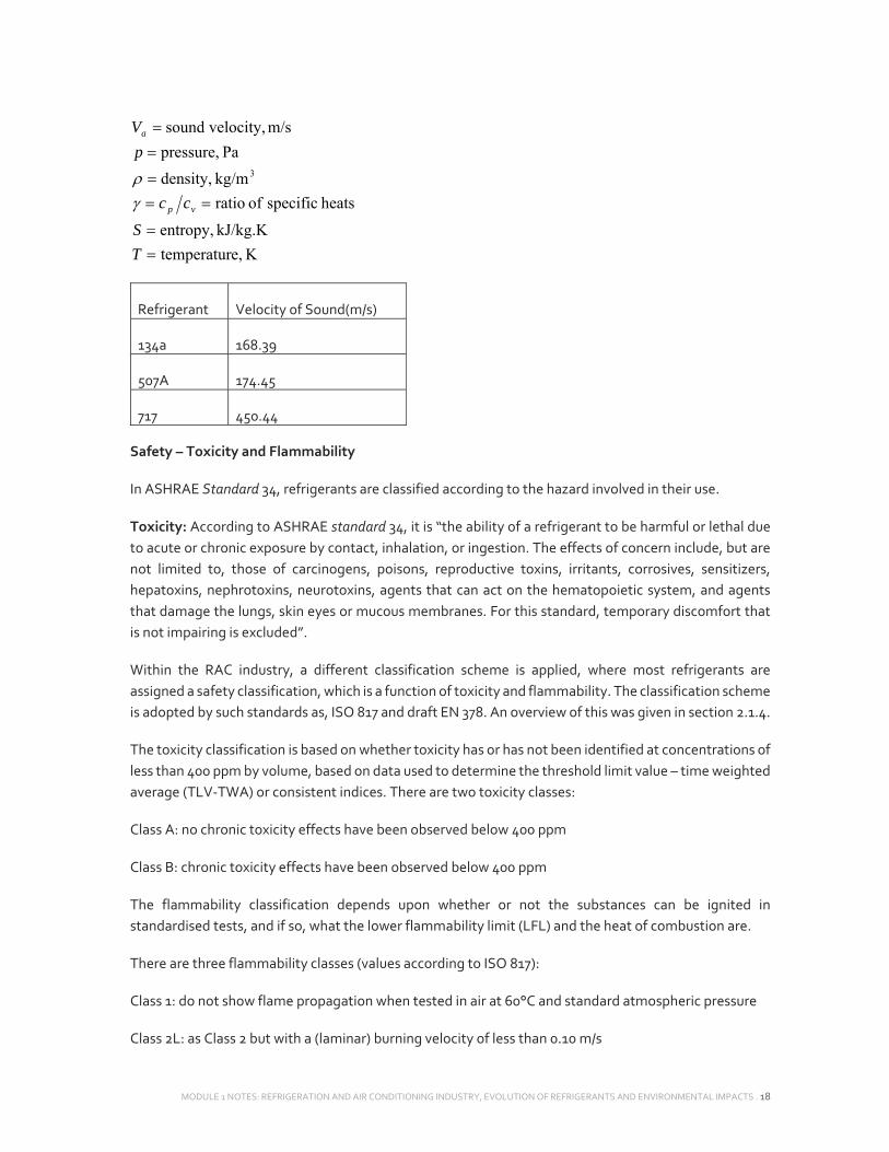
Sound Velocity: The velocity of sound is the maximum velocity that can be reached inside the
refrigeration pipes. The practical velocity of a gas in piping or through openings is limited by the velocity
of sound. The table shows the velocity of sound in the vapor phase of some refrigerants. The velocity
increases when the temperature is increased at constant pressure. The velocity decreases when the
pressure is increased at constant temperature.
Velocity of Sound
The velocity of sound in vapor is calculated by:
a
S T
p pV
MODULE 1 NOTES: REFRIGERATION AND AIR CONDITIONING INDUSTRY, EVOLUTION OF REFRIGERANTS AND ENVIRONMENTAL IMPACTS . 18
K e,temperatur
kJ/kg.K entropy,
heats specific of ratio
kg/m density,
Pa pressure,
m/s velocity,sound
3
T
S
cc
p
V
vp
a
Refrigerant Velocity of Sound(m/s)
134a 168.39
507A 174.45
717 450.44
Safety – Toxicity and Flammability
In ASHRAE Standard 34, refrigerants are classified according to the hazard involved in their use.
Toxicity: According to ASHRAE standard 34, it is “the ability of a refrigerant to be harmful or lethal due
to acute or chronic exposure by contact, inhalation, or ingestion. The effects of concern include, but are
not limited to, those of carcinogens, poisons, reproductive toxins, irritants, corrosives, sensitizers,
hepatoxins, nephrotoxins, neurotoxins, agents that can act on the hematopoietic system, and agents
that damage the lungs, skin eyes or mucous membranes. For this standard, temporary discomfort that
is not impairing is excluded”.
Within the RAC industry, a different classification scheme is applied, where most refrigerants are
assigned a safety classification, which is a function of toxicity and flammability. The classification scheme
is adopted by such standards as, ISO 817 and draft EN 378. An overview of this was given in section 2.1.4.
The toxicity classification is based on whether toxicity has or has not been identified at concentrations of
less than 400 ppm by volume, based on data used to determine the threshold limit value – time weighted
average (TLV‐TWA) or consistent indices. There are two toxicity classes:
Class A: no chronic toxicity effects have been observed below 400 ppm
Class B: chronic toxicity effects have been observed below 400 ppm
The flammability classification depends upon whether or not the substances can be ignited in
standardised tests, and if so, what the lower flammability limit (LFL) and the heat of combustion are.
There are three flammability classes (values according to ISO 817):
Class 1: do not show flame propagation when tested in air at 60°C and standard atmospheric pressure
Class 2L: as Class 2 but with a (laminar) burning velocity of less than 0.10 m/s

MODULE 1 NOTES: REFRIGERATION AND AIR CONDITIONING INDUSTRY, EVOLUTION OF REFRIGERANTS AND ENVIRONMENTAL IMPACTS . 19
Class 2: exhibit flame propagation when tested at 60°C and atmospheric pressure, but have a LFL higher
than 3.5% by volume, and have a heat of combustion of less than 19,000 kJ/kg
Class 3: exhibit flame propagation when tested at 60°C and atmospheric pressure, but have an LFL at or
less than 3.5% by volume, or have a heat of combustion that is equal to or greater than 19,000 kJ/kg
Class 2L is now included in ISO 817, ISO 5149 and proposed for inclusion in EN 378. It is primarily intended
to differentiate between HFC‐152a and the remainder of class 2 refrigerants (such as R‐717, HFC‐32 and
HFC‐1234yf), which tend to be more difficult to ignite and is less likely to evolve overpressures that could
cause damage.
Typically, a “higher” the classification – that is toxicity Class B instead of Class A, and flammability Class
3 instead of Class 1 – means that the refrigerating system has more onerous design requirements
associated with it, in order to handle the higher risk presented by the refrigerant.
Lower Flammability Limit
The lower flammability limit (LFL) of flammable refrigerants is typically applied as a constraint to the
amount of refrigerant that can be released into a room or enclosure, as it represents the smallest quantity
that, when in the presence of an active source of ignition, could sustain a flame.
Acute Toxicity Exposure Limit
The acute toxicity exposure limit (ATEL) of any refrigerant may also applied as a constraint to the amount
of refrigerant that can be released into a room or enclosure, as it represents the smallest quantity that
could impose adverse toxicological effects onto occupants.
Practical Limit
There is a further safety measure for the application of refrigerants, termed the practical concentration
limit (PL). This represents the highest concentrations level in an occupied space which will not result in
any escape impairing (i.e., acute) effects. Thus, it is principally, the lowest “dangerous” concentration of
a refrigerant, with a safety factor applied. The estimation of PL is based on the lowest of the following:

MODULE 1 NOTES: REFRIGERATION AND AIR CONDITIONING INDUSTRY, EVOLUTION OF REFRIGERANTS AND ENVIRONMENTAL IMPACTS . 20
Acute toxicity exposure limit (ATEL), based on mortality (in terms of LC50) and/or cardiac sensitization,
and/or anaesthetic or central nervous system (CNS) effects
Oxygen deprivation limit (ODL)
20% of the lower flammability limit (or 25% in ASHRAE 34)
For class A1 (and A2L) and class B refrigerants, the PL is normally based on the ATEL, whereas for A2 and
A3 refrigerants it is normally dictated by the LFL. For some refrigerants the PL is based on historical use
experience.
Refrigerants Effects:
In 1987, researchers concluded that the chemical compounds in our most widely used refrigerants known
as chlorofluorocarbons (CFCs) are a major source of destruction to the lower atmosphere. Research
showed that once CFCs reach the atmosphere, the sun’s ultraviolet rays break down the compound, thus
releasing chlorine which impact the ozone layer badly.
Types of Impacts:
Direct impact: occurs from the leakage of refrigerant gases into the atmosphere. This can lead to ozone
depletion and global warming via the greenhouse effect.
Indirect impact: due to the energy consumption of refrigeration and air conditioning systems leading to
CO2 emissions that cause global warming.
e. Classification:
Refrigerants can be broadly classified based on the following:
Working Principle:
Under this heading, we have the primary or common refrigerants and the secondary refrigerants.
The primary refrigerants are those that pass through the processes of compression, cooling or
condensation, expansion and evaporation or warming up during cyclic processes. Ammonia, R12, R22,
carbon dioxide come under this class of refrigerants.
On the other hand, the medium which does not go through the cyclic processes in a refrigeration system
and is only used as a medium for heat transfer are referred to as secondary refrigerants. Water, brine
solutions of sodium chloride and calcium chloride come under this category.
Safety Considerations:
Under this heading, we have the following three sub‐divisions.
Safe refrigerants: non‐toxic, non‐flammable such as R114, methyl chloride, carbon dioxide, water etc.

MODULE 1 NOTES: REFRIGERATION AND AIR CONDITIONING INDUSTRY, EVOLUTION OF REFRIGERANTS AND ENVIRONMENTAL IMPACTS . 21
Toxic and moderately flammable: dichloroethylene methyl format, ethylchloride, sulphur dioxide,
ammonia etc. Highly flammable refrigerants: butane, isobutene, propane, ethane, methane, ethylene
etc.
Chemical Compositions:
Halocarbon compounds: These are obtained by replacing one or more hydrogen atoms in ethane or
methane with halogens.
Azeotropes: These are the mixtures of two or more refrigerants and behave as a compound.
Oxygen and Nitrogen Compounds: Refrigerants having either oxygen or nitrogen molecules in their
structure, such as ammonia, are grouped separately and have a separate nomenclature from the
halogenated refrigerants.
Cyclic organic Compounds: The compounds coming under this class are R316, R317 and R318.
Inorganic Compounds: These are further divided into two categories: Cryogenic and Non‐cryogenic.
Cryogenic fluids are those which are applied for achieving temperatures as low as – 160 °C to – 273 °C.
The inorganic compounds which are employed above the cryogenic temperature ranges come under the
remaining sub‐division of inorganic refrigerants.
Unsaturated Compounds: Compounds such as ethylene, propylene etc. are grouped under this head and
grouped under the 1000 series for convenience.
Miscellaneous: This group contains those compounds which cannot be grouped under the other
components. They are indicated by the 700 series with the last numbers being their molecular weight.
Examples include air, carbon dioxide, sulphur dioxide etc.
f. Designation:
As we can see from the above sub‐divisions, they are not mutually exclusive. A compound may come
under more than one sub‐division. Hence, the importance of adopting the various naming conventions
to designate the different refrigerants cannot be underestimated. Since a large number of refrigerants
have been developed over the years for a wide variety of applications, a numbering system has been
adopted to designate various refrigerants. All the refrigerants are designated by R followed by a unique
number.
Fully saturated, halogenated compounds: These refrigerants are derivatives of alkanes (CnH2n+2) and
designated by R XYZ, where:
X+1 indicates the number of Carbon (C) atoms
Y‐1 indicates number of Hydrogen (H) atoms
Z indicates number of Fluorine (F) atoms
The balance indicates the number of Chlorine atoms. Only 2 digits indicate that the value of X is zero.

MODULE 1 NOTES: REFRIGERATION AND AIR CONDITIONING INDUSTRY, EVOLUTION OF REFRIGERANTS AND ENVIRONMENTAL IMPACTS . 22
Example 1: Calculate the chemical formula of refrigerant R134a:
According to the above mentioned convention:
No. of C atoms: C – 1 = 1 => C = 2
No. of H atoms: H + 1 = 3 => H = 2
No. of F atoms: F = 4
No. of Cl atoms: Cl = 0
The compound is C2H2F4 and its name is Tetra‐fluoro‐ethane
Inorganic refrigerants: These are designated by number 7 followed by the molecular weight of the
refrigerant (rounded‐off).
Ex.: Ammonia: Molecular weight is 17, the designation is R 717
Carbon dioxide: Molecular weight is 44, the designation is R 744
Water: Molecular weight is 18, the designation is R 718
g. Blends
Blends: Refrigerants consisting of mixtures of two or more different chemical compounds, often used
individually as refrigerants for other applications.
A simple mixture (Zeotropes): When two liquids are mixed, a simple mixture, or a zoetrope, is formed if
the vapor pressure of the mixture at a given temperature is between the vapor pressures of the two
components.
The relationship between vapor pressure and concentration is :
Raoult’s law: A A AP X VP
B B BP X VP
Dalton’s law: A B TP P P
where: or A BP P = partial pressure of component A or B in the solution
AX or BX = mol fraction of each component in the mixture
or A B
VP VP = vapor pressure of pure component

MODULE 1 NOTES: REFRIGERATION AND AIR CONDITIONING INDUSTRY, EVOLUTION OF REFRIGERANTS AND ENVIRONMENTAL IMPACTS . 23
TP = vapor pressure of solution
When the vapor pressure of the mixture is equal to the sum of the partial pressures of the components,
as calculated by Dalton’s law, the solution is said to be “ideal”
Zeotropic blends comprise multiple components of different volatilities that, when used in refrigeration
cycles, change volumetric composition and saturation temperatures as they evaporate or condense at
constant pressure.
Azeotropic: Blends comprising multiple components of different volatilities that, when used in
refrigeration cycles, do not change volumetric composition or saturation temperature as they evaporate
or condense at constant pressure.
Azeotropes are formed when the vapor pressure of the solution is greater than that of each pure
component.
Near Azeotropic: a zeotropic blend with a temperature glide sufficiently small that it may be disregarded
without consequential error in analysis for a specific application.
• Temperature Glide: the difference between the starting and ending temperatures of a
refrigerant phase change within a system at any constant pressure. At a given pressure, the blend
evaporates and condenses at a range of temperatures. The total temperature glide of a refrigerant
blend is defined as the temperature difference between the saturated vapor temperature and
the saturated liquid temperature at a constant pressure. Another definition is the temperature
difference between the starting and ending temperature of a refrigerant phase change within a
system at a constant pressure. When the liquid refrigerant boils in the evaporator, the
composition of the liquid and vapor phases are different. The liquid phase becomes richer in the
higher‐boiling‐point component as the low‐boiling‐point components boil off into the vapor
phase. In the condenser, the refrigerant changes phase (condenses) from a vapor to a liquid.
Refrigerant blends exhibit temperature glide because there’s more than one molecule present in
their compositional makeup. (http://www.achrnews.com/articles/130707‐the‐professor‐the‐
correlation‐between‐refrigerant‐blends‐and‐temperature‐glide)
Number Designation for Blends:
Blends are designated by their respective refrigerant numbers and weight proportions. Refrigerants are
named in order of increasing normal boiling points of the components.

MODULE 1 NOTES: REFRIGERATION AND AIR CONDITIONING INDUSTRY, EVOLUTION OF REFRIGERANTS AND ENVIRONMENTAL IMPACTS . 24
Number Designation for Azeotropic Blends:
Azeotropic blends are assigned an identifying number in the 500 series. It is not necessary to cite the
percentages of weight in parentheses here.
The previous mentioned substances although they have high efficiencies in the refrigeration and air
conditioning systems, but they have been proved to be environmentally harmful, especially since they
are used in wide applications.
These harmful substances are called Ozone Depleting Substances. They are widely spread by the human
harmful practices, and they have direct effect on the ozone layer and consequently affect the global
warming.
5. ENVIRONMENTALLY HARMFUL PRACTICES
The environmentally harmful practices that are considered the major sources of Green House Gases
GHGs and the cause of Ozone Depletion and Global Warming are: products that involve CFCs or halons
during either manufacture or use and the burning of huge quantities of oil, gasoline, and coal: such
activities have increased the amount of GHGs, so that 1998 was recorded as the warmest year.
6. STRUCTURE OF THE ATMOSPHERE (OZONE LAYERING)
The atmosphere is composed of several layers with different characteristics. In the context of ozone
depletion, the lowest two layers of the atmosphere are the most important. These are:
Troposphere: extending from the earth’s Surface to an altitude of around 10 km. This layer is
characterized by large scale turbulence and mixing. All weather phenomena occur in this layer. An
important characteristic is the temperature decrease with altitude, starting form an average of 15°C at
the earth’s surface and reaching ‐55°C at the tropopause. The temperature decrease is due to the weight
of air causing differences in pressure over a range of heights, and the laws of thermodynamics (such as
the ideal gas law) show that pressure changes are accompanied by temperature changes. The thickness
of this layer is not the same everywhere; it is as high as 16 km in Tropics and as low as 9 km in Polar
Regions.
Stratosphere: Occupying the interval 10‐45 km above the earth’s surface. The temperature structure of
this layer is different than that of the troposphere mainly due to the presence of ozone which absorbs
solar energy and releases it as heat. Since 90% of the ozone is found in the stratosphere; therefore, this
layer is called the ozone layer. Ozone has the same chemical structure whether it occurs miles above the
earth or at ground level and can be:“Good” ozone occurs naturally in the stratosphere approximately 10

MODULE 1 NOTES: REFRIGERATION AND AIR CONDITIONING INDUSTRY, EVOLUTION OF REFRIGERANTS AND ENVIRONMENTAL IMPACTS . 25
to 30 miles above the earth's surface and forms a layer that protects life on earth from the sun's harmful
rays. In the earth's lower atmosphere, ground‐level ozone (or smog) is considered “bad”.
VOC + NOx + Sunlight = Ozone
Types of UV Radiation
UV‐A: Wavelengths greater than 320 nm, not radically absorbed by ozone, needed in humans for the
formation of Vitamin D.
UV‐B: Wavelengths between 280 and 320 nm, large amount of UV‐B range blocked out by ozone,
primarily affects exposed organs such as the skin and the eyes
UV‐C: Wavelengths between 200 and 280 nm, totally removed by stratospheric ozone, causes severe
biological consequences.
Each 1% of depletion in stratospheric ozone increases exposure to damaging ultraviolet radiation by 1.5
to 2 percent. [EPA]
How is Ozone Produced?
Ozone is produced naturally in the upper stratosphere when ultraviolet radiation from the sun strikes
molecules of oxygen and dissociates them. This process of O2 dissociation is called photolysis. Upon
dissociation, O2 liberates a free oxygen atom. This atom can then combine with another O2 molecule to
create ozone. The dissociation of O2 requires ultraviolet (UV) light of wavelength shorter than 240 nm.
Most of the ozone in the stratosphere is formed over the equatorial belt, where the level of solar radiation
is greatest. The circulation in the atmosphere then transports it towards the pole. So, the amount of
stratospheric ozone above a location on the Earth varies naturally with latitude, season, and from day‐
to‐day.

MODULE 1 NOTES: REFRIGERATION AND AIR CONDITIONING INDUSTRY, EVOLUTION OF REFRIGERANTS AND ENVIRONMENTAL IMPACTS . 26
7. ODS AND APPLICATIONS
An ozone‐depleting substance (ODS) is a chemical substance, usually consisting of some combination of
chlorine, fluorine, or bromine plus carbon, such as CFC and HCFC that has been shown to destroy the
ozone. Ozone depleting substances, (ODS), damage the ozone layer which protects life on earth from
harmful ultraviolet rays. They degrade slowly and can remain intact for many years. One chlorine or
bromine molecule can destroy 100,000 ozone molecules, causing ozone to disappear much faster than
nature can replace it. Ozone depleting substances, (ODS), damage the ozone layer which protects life on
earth from harmful ultraviolet rays. They degrade slowly and can remain intact for many years
ODSs are divided into two classes:
Class I: includes the fully halogenated CFCs, halons, and the ODSs that are the most threatening to the
ozone layer, with an ODP of 0.2 or higher.
Class II: substances that are known or reasonably anticipated to have harmful effects on the stratospheric
ozone layer such as HCFC, with an ODP of less than 0.2
List of Some ODS Used:
ODS Chemical Formula Uses
Cyclobutane Or RC‐316c
C4Cl2F6 Testing as a solvent in aerospace industry
Hexachlorobutadiene (or HCBD)
C4Cl6 Solvent applications as well as an intermediate in the production of HFCs.
n‐propyl bromide (or 1‐bromopropane, CH2BrCH2CH3 and nPB)
1‐C3H7Br or CH2BrCH2CH3 Solvent applications, including degreasing, vapor cleaning and cold cleaning of metal parts
Halon‐1202 CBr2F2 In fire protection systems for military‐type aircraft. By‐product which may be generated during production of Halon 1301 and 1211.

MODULE 1 NOTES: REFRIGERATION AND AIR CONDITIONING INDUSTRY, EVOLUTION OF REFRIGERANTS AND ENVIRONMENTAL IMPACTS . 27
Carbon tetrachloride and methyl chloroform: Chlorine containing chemicals widely used as solvents for
cleaning. Carbon tetrachloride (CTC) is a very effective chlorinated solvent used for cleaning processes in
developing countries:
- discovered in 1839
- became popular for metal degreasing from the late 1890s and as a dry cleaning solvent in the
1930s
- replaced by perchloroethylene in the late 1950s.
- cheapest of all chlorocarbon solvents yet toxic and carcinogenic.
- has an ODP of 1.1, the highest of all the common solvents
Between 1950 and 1980, 1,1,1‐trichloroethane became popular to replace other chlorocarbons.
- initially used as a cold‐cleaning solvent and as a solvent for some classes of adhesives in addition
to dry cleaning in the Far East and Japan
- has a lower toxicity than other solvents
- has a relatively low ODP (0.1) but it has significant impact on the ozone layer because of the
volume used.
- has a moderately low price, but slightly higher than all the other chlorinated solvents
- The impact of these substances is measured by their ODP, GWP and their lifetime. The life time
factor is very important to be taken into consideration, since CFCs are so stable, that some have
atmospheric lifetimes of over 100 years and they don’t break down easily.
- Therefore, it is desirable to select refrigerants with low lifetimes.
- Examples of Some Substances and Their ODP , GWP and Life Time
Refrigerant Name ODP GWP Life time
R124 0.03 610 5.8
R134a 0 1430 14.6
R404A 0 3920 40.36
Because of the harmful effects of the ODS, many treaties and conventions were issued, to agree on a
schedule for phasing out these substances. These treaties banned the use of some ODS completely and
put other schedule and timelines for phasing out of other substances that are currently in use. Also, there
is a process of monitoring and follow up of the phase out plan worldwide.

MODULE 1 NOTES: REFRIGERATION AND AIR CONDITIONING INDUSTRY, EVOLUTION OF REFRIGERANTS AND ENVIRONMENTAL IMPACTS . 28
8. MULTI‐LATERAL ENVIRONMENTAL AGREEMENTS
i. Vienna Convention
ii. Montreal Protocol on Substances that Deplete the Ozone Layer (1987)
iii. Basel Convention on the Control of Transboundary Movements of Hazardous Wastes and Their
Disposal (1989)
iv. Kyoto Protocol on Climate Change (1997)
v. Rotterdam Convention on the Prior Informed Consent Procedure for Certain Hazardous
Chemicals and Pesticides in International Trade (PICs) (1998)
vi. Stockholm Convention on Persistent Organic Pollutants (POPs) (2001)
i. Vienna Convention (1985)
The 1985 Vienna Convention encourages intergovernmental cooperation on:
• international research
• systematic observation of the ozone layer
• monitoring of CFC production
• the exchange of data on emission, and on concentrations of CFCs and halons.
Following are the major issues raised by the Vienna Protocol:
• Parties participating should seek to protect human health and the environment against adverse
effects resulting from ODS activities
• Parties should initiate and undertake cooperatively research and scientific assessment on
physical and chemical processes that may affect the ozone layer.
• Parties should transmit the information they have to others.
• In 1985 also, the Antarctic “ozone hole” was discovered.
• Scientific data confirmed that chlorine from CFCs and bromine from halons and methyl bromide
are responsible for ozone destruction and for the ozone hole itself. The discovery of the Antarctic
hole increased the international cooperation initiated by the Vienna convention.
Montreal Protocol on Substances that Deplete the Ozone Layer (1987) pdfweb
Following the discovery of the Antarctic ozone hole in late 1985, governments recognized the need for
stronger measures to reduce the production and consumption of a number of CFCs (CFC 11, 12, 113, 114,
and 115), several Halons (1211, 1301, 2402), HCFCs, methyl bromide and several other ODSs. The

MODULE 1 NOTES: REFRIGERATION AND AIR CONDITIONING INDUSTRY, EVOLUTION OF REFRIGERANTS AND ENVIRONMENTAL IMPACTS . 29
Montreal Protocol on Substances that Deplete the Ozone Layer was adopted on 16 September 1987 at
the Headquarters of the International Civil Aviation Organization in Montreal. The Protocol came into
force on 1st January 1989, when it was ratified by 29 countries and the EEC. Since then several other
countries have ratified it.
The Protocol was designed so that the phase out schedules could be revised on the basis of periodic
scientific and technological assessments. Following such assessments, the Protocol was adjusted to
accelerate the phase out schedules. It has also been amended to introduce other kinds of control
measures and to add new controlled substances to the list.
Control Measures and Phase out Schedule Under the Montreal Protocol
The ozone layer can only return to its 1970s status if all nations join in the effort to eliminate the emission
of ozone‐depleting substances into the atmosphere. Failure to ratify the ozone treaties may hinder
international efforts to protect the earth from the damage caused by ozone‐layer depletion. While such
damage will have a global impact, developing countries are likely to be the most severely affected.
The Montreal Protocol and its Amendments constitute a mechanism for the phasing out of ozone
depleting substances. Parties to the Protocol are committed to this goal.
The control measures and phase out schedules cover both the production and the consumption of the
target substances. However, even after phase out both developed and developing countries are
permitted to produce limited quantities in order to meet the essential uses for which no alternatives have
yet been identified.
Article 5 Countries
As per Article 5 of the Montreal Protocol, any country that is a developing country and whose annual
consumption of the controlled substances is less than 0.3 kg per capita is considered as Article 5 country.
Such countries are allowed a delay of ten years to comply with the control measures of the Montreal
Protocol in order to meet its basic domestic needs.

MODULE 1 NOTES: REFRIGERATION AND AIR CONDITIONING INDUSTRY, EVOLUTION OF REFRIGERANTS AND ENVIRONMENTAL IMPACTS . 30
Ninety six (96) chemicals are presently controlled by the Montreal Protocol, including:
Halo carbons, notably chlorofluorocarbons (CFCs)
Halons:
Carbon tetrachloride
Methyl chloroform (1,1,1 trichloroethane)
Hydrobromofluorocarbons (HBFCs)
Hydrochlorofluorocarbons (HCFCs)
Methyl bromide (CH3Br)
Bromochloromethane (BCM), a new ozone‐depleting substance that some companies sought to
introduce into the market in 1998, has been targeted by the 1999 Ammendment for immediate phase‐
out to prevent its use.
The phase out schedules for developed, (Non‐Article 5), countries are as follows:
Halons: Phase out by 1994
CFCs, carbon tetrachloride, methyl chloroform, and HBFCs: Phase out by 1996
Methyl bromide:
Reduce by 25% by 1999
Reduce by 50% by 2001
Reduce by 70% by 2003
Phase out by 2005
HCFCs:
Reduce by 35% by 2004

MODULE 1 NOTES: REFRIGERATION AND AIR CONDITIONING INDUSTRY, EVOLUTION OF REFRIGERANTS AND ENVIRONMENTAL IMPACTS . 31
Reduce by 65% by 2010
Reduce by 90% by 2015
Reduce by 99.5% by 2020 with 0.5% permitted for maintenance purposes only
Phase out by 2030
Compliance Assistant Program (CAP)
CAP is a team of UNEP staff located in UNEP's regional offices (such as the Region of West Asia, ROWA).
The CAP program is designed to:
Speed up project implementation and the quality of services provided to developing countries to support
compliance with the Montreal Protocol.
Deliver compliance assistance directly to countries, in each respective region, on the ground and work
closely with countries on an on‐going basis.
Assist countries to prioritize their needs and project proposals through direct interaction with ozone
officers
Some of CAP’s planned activities of the phase‐out plan for the Multilateral Fund include:
Providing direct technical and policy assistance to enable and sustain compliance.
Assisting Low‐Volume ODS‐Consuming countries (LVCs). This assistance will include Institutional
Strengthening, Country Program (CP) and Refrigerant Management Plans (RMP) update, RMP
implementation and other non‐investment support.
For most of the LVCs, the refrigeration sector is the largest ODS consumption sector, and the successful
implementation of these RMP activities will largely determine whether or not the countries meet the CFC
compliance targets.
Basel Convention on the Control of Transboundary Movements of Hazardous Wastes and
Their Disposal (1989) (Reference: http://archive.basel.int/convention/basics.html)

MODULE 1 NOTES: REFRIGERATION AND AIR CONDITIONING INDUSTRY, EVOLUTION OF REFRIGERANTS AND ENVIRONMENTAL IMPACTS . 32
In the late 1980s, a tightening of environmental regulations in industrialized countries led to a dramatic
rise in the cost of hazardous waste disposal. Searching for cheaper ways to get rid of the wastes, “toxic
traders” began shipping hazardous waste to developing countries and to Eastern Europe. When this
activity was revealed, international outrage led to the drafting and adoption of the Basel Convention.
Examples of wastes include (clinical wastes from hospitals, pharmaceutical wastes, household wastes,
waste resulting from surface treatment of metals and plastics, explosive and flammable wastes.)
During its first Decade (1989‐1999), the Convention was principally devoted to setting up a framework
for controlling the “transboundary” movements of hazardous wastes, that is, the movement of
hazardous wastes across international frontiers. It also developed the criteria for “environmentally sound
management”. A Control System, based on prior written notification, was also put into place.
The Secretariat, in Geneva, Switzerland, facilitates the implementation of the Convention and related
agreements. It also provides assistance and guidelines on legal and technical issues, gathers statistical
data, and conducts training on the proper management of hazardous waste. The Secretariat is
administered by UNEP.
Entry into force: 5 May 1992.
Kuwait ratified the agreement on October 10th, 1993.
Lebanon ratified the agreement on December 21st, 1994.
Guidelines for the Convention’s activities during the next decade include:
Active promotion and use of cleaner technologies and production methods;
Further reduction of the movement of hazardous and other wastes;
The prevention and monitoring of illegal traffic;
Improvement of institutional and technical capabilities ‐through technology when appropriate ‐
especially for developing countries and countries with economies in transition;
Further development of regional and sub regional centers for training and technology transfer.
Kyoto Protocol on Climate Change (1997) (Reference:
http://www.pic.int/TheConvention/Overview/History/tabid/1045/language/en‐US/Default.aspx)

MODULE 1 NOTES: REFRIGERATION AND AIR CONDITIONING INDUSTRY, EVOLUTION OF REFRIGERANTS AND ENVIRONMENTAL IMPACTS . 33
In 1992, 154 nations joined an international treaty, the United Nations Framework Convention on
Climate Change, to begin to consider what can be done to reduce global warming and to cope with
whatever temperature increases are inevitable. The treaty aimed at reducing emissions of greenhouse
gases in order to combat global warming. Its stated objective was “to achieve stabilization of greenhouse
gas concentrations in the atmosphere at a low enough level to prevent dangerous anthropogenic (man‐
made) interference with the climate system”. The treaty, originally, set no mandatory limits on
greenhouse gas emissions and contained no enforcement provisions. However, the treaty included
provisions for update (called “protocols”) that would set mandatory emission limits. The principle update
is the Kyoto Protocol, which has become much better known than the UNFCCC itself.
The Kyoto Protocol came into force on February 16, 2005. A total of 156 countries ratified the agreement.
According to UNEP press release: “The Kyoto Protocol is an agreement under which industrialized
countries will reduce their collective emissions of greenhouse gases by 5.3% compared to the year 1990
(but note that, compared to the emission levels that would be expected by 2010 without the Protocol,
this target represents a 29% cut). The goal is to lower overall emissions from six greenhouse gases –
carbon dioxide, methane, nitrous oxide, sulfur hexafluoride, HFCs and PFCs – calculated as an average
over the five‐year period of 2008‐12. National targets range from 8% reductions for the European Union
and some others to 7% for the US, 6% for Japan, 0% for Russia, and permitted increases of 8% for
Australia and 10% for Iceland”.
GHGs that fall under the Kyoto Protocol are:
Carbon dioxide (CO2), Methane (CH4), Nitrous Oxide (N2O), Hydrofluorocarbons (HFCs),
Perfluorpcarbons (PFCs) and Sulphur hexafluoride (SF6).
Sources of such GHGs:
Fuel combustion (transport sector, power plants…), mineral products, chemical industry, agriculture
(manure management, rice cultivation…)
Developing countries have no immediate restrictions under the UNFCCC for several reasons. First, to
avoid restriction on growth, since pollution is strongly linked to industrial growth. Second, to prevent
developing countries from selling emission credits to industrialized countries to permit them to over‐
pollute.
Kuwait ratified the UNFCCC agreement on December 28, 1994 and entered into force on March 28, 1995.
Kuwait also ratified the Kyoto Protocol on March 11, 2005 and entered into force on June 9, 2005. It
signed as a non‐Annex I party, meaning, it does not fall under the restrictions of either the UNFCCC or
the Kyoto Protocol agreements.
Lebanon ratified the UNFCCC agreement on December 15, 1994 and entered into force on March 15,
1995. However, Lebanon has not yet ratified the Kyoto Protocol (UNFCCC 2006).
Rotterdam Convention on the Prior Informed Consent Procedure for Certain Hazardous
Chemicals and Pesticides in International Trade (PICs) (1998) (Reference:

MODULE 1 NOTES: REFRIGERATION AND AIR CONDITIONING INDUSTRY, EVOLUTION OF REFRIGERANTS AND ENVIRONMENTAL IMPACTS . 34
http://www.agriculture.gov.bb/agri/index.php?option=com_content&id=407:pesticides‐control‐board‐
knowledge‐centre&Itemid=99)
The dramatic growth in chemical production and trade during the past three decades has raised concerns
about the potential risks posed by hazardous chemicals and pesticides. Countries lacking adequate
infrastructure to monitor the import and use of these chemicals are particularly vulnerable.
The Rotterdam Convention is a multilateral environmental agreement designed to enable the world to
monitor and control the trade in certain hazardous chemicals in order to protect human health and the
environment from potential harm and to contribute to their environmentally sound use. It is not a
recommendation to ban the global trade or use of specific chemicals. It is rather an instrument to provide
importing Parties with the power to make informed decisions on which chemicals they want to receive
and to exclude those they cannot manage safely. The Convention covers the 22 hazardous pesticides and
500 industrial chemicals. See handout for a list of the chemicals and pesticides.
The Convention entered into force on 24 February 2004 and became legally binding for its 170 Parties.
Kuwait signed the convention on September 11th, 1998. Lebanon has not yet signed the convention.
The objectives of the Convention are:
to promote shared responsibility and cooperative efforts among Parties in the international trade of
certain hazardous chemicals in order to protect human health and the environment from potential harm;
and
to contribute to the environmentally sound use of those hazardous chemicals, by facilitating information
exchange about their characteristics, by providing for a national decision‐making process on their import
and export and by disseminating these decisions to Parties.
The Convention promotes the exchange of information on a very broad range of chemicals. It does so
through:
the requirement for a Party to inform other Parties of each national ban or severe restriction of a
chemical;
the possibility for Party which is a developing country or a country in transition to inform other Parties
that it is experiencing problems caused by a severely hazardous pesticide formulation under conditions
of use in its territory;
the requirement for a Party that plans to export a chemical that is banned or severely restricted for use
within its territory, to inform the importing Party that such export will take place, before the first
shipment and annually thereafter;
the requirement for an exporting Party, when exporting chemicals that are to be used for occupational
purposes, to ensure that an up‐to‐date safety data sheet is sent to the importer; and
labeling requirements for exports of chemicals included in the PIC procedure, as well as for other
chemicals that are banned or severely restricted in the exporting country.

MODULE 1 NOTES: REFRIGERATION AND AIR CONDITIONING INDUSTRY, EVOLUTION OF REFRIGERANTS AND ENVIRONMENTAL IMPACTS . 35
Stockholm Convention on Persistent Organic Pollutants (POPs) (2001) (Reference:
http://www.chemsafetypro.com/Topics/Convention/Stockholm_Convention_on_Persistent_Organic_Pollu
tants_POPs.html)
Persistent Organic Pollutants, (POPs), are chemicals that possess toxic properties, resist degradation,
bioaccumulate (accumulate in the fatty tissue of living organisms), and are transported, through air,
water and migratory species, across international boundaries and deposited far from their place of
release, where that accumulate in terrestrial and aquatic ecosystems. Some of these substances are
pesticides, while others are industrial chemicals or unwanted by‐products of industrial processes or
combustion.
Examples of POPs used in daily life include: DDT, secondary copper, aluminum and zinc productions,
open burning of waste, fossil fuel industrial burners, leaded gasoline motor vehicles, textile and leather
dying, etc… (See handout for a complete list).
Specific effects of POPs can include cancer, allergies and hypersensitivity, damage to the central and
peripheral nervous systems, reproductive disorders, and disruption of the immune system. Some POPs
are also considered to be endocrine disrupters, which, by altering the hormonal system, can damage the
reproductive and immune systems of exposed individuals as well as their offspring.
The Stockholm Convention is a global treaty to protect human health and the environment from
POPs. POPs circulate globally and can cause damage wherever they travel. In implementing the
Convention, Governments will take measures to eliminate or reduce the release of POPs into the
environment. The convention has not yet come into force.
The Convention on POPs is a major achievement that is complemented by a number of other chemicals‐
related global or regional Conventions, Agreements, and Action Plans, primarily the Basel “Convention
on the Control of Transboundary Movements of Hazardous Wastes and their Disposal,” and the
Rotterdam “Convention on the Prior Informed Consent (PIC) Procedure for Certain Hazardous Chemicals
and Pesticides in International Trade”.
The convention focuses initially on twelve chemicals that can be grouped into the following three
categories:
Pesticides–aldrin, chlordane, DDT, dieldrin, endrin, heptachlor, exachlorobenzene (also an industrial
chemical and unintended byproduct), mirex and toxaphene.
Industrial chemicals – PCBs (also unintended by‐products).
Unintended by‐products – dioxins and furans.
Kuwait and Lebanon both signed the Stockholm convention on May 23, 2001.
Because of the previously mentioned human practices, many environmental issues were observed. The
most important ones were recorded to be the global warming and the green house effect.

MODULE 1 NOTES: REFRIGERATION AND AIR CONDITIONING INDUSTRY, EVOLUTION OF REFRIGERANTS AND ENVIRONMENTAL IMPACTS . 36
The mentioned conventions and treaties played an important role in reducing the rate of spreading of
these phenomena, but no one can deny that they exist and their effects are highly noticed. Also, their
effects will be more serious if countries do not work together and obey the banning treaties to reduce
the effect of the ODS.
9. GLOBAL WARMING
a. Definition:
Earth like any other object absorbs part of the sun light and reflects the other part. The emission of some
substances(ODS=CFC) in the atmosphere reduces the reflection ability of earth and created what have
been called “The Green House Effect” or “The Global Warming”.
The planet is warming, from North Pole to South Pole, and everywhere in between. Globally, the mercury
is already up more than 1 degree Fahrenheit (0.8 degree Celsius), and even more in sensitive Polar
Regions. And the effects of rising temperatures aren’t waiting for some far‐flung future. They’re
happening right now. Signs are appearing all over, and some of them are surprising. The heat is not only
melting glaciers and sea ice, it’s also shifting precipitation patterns and setting animals on the move.
b. Effects:
Some impacts from increasing temperatures are already happening. (Reference: IPCC, 2007)
Ice is melting worldwide, especially at the Earth’s poles. This includes mountain glaciers, ice sheets
covering West Antarctica and Greenland, and Arctic sea ice.
Researcher Bill Fraser has tracked the decline of the Adélie penguins on Antarctica, where their numbers
have fallen from 32,000 breeding pairs to 11,000 in 30 years.
Sea level rise became faster over the last century.
Some butterflies, foxes, and alpine plants have moved farther north or to higher, cooler areas.
Precipitation (rain and snowfall) has increased across the globe, on average.
Spruce bark beetles have boomed in Alaska thanks to 20 years of warm summers. The insects have
chewed up 4 million acres of spruce trees.

MODULE 1 NOTES: REFRIGERATION AND AIR CONDITIONING INDUSTRY, EVOLUTION OF REFRIGERANTS AND ENVIRONMENTAL IMPACTS . 37
Other effects could happen later this century, if warming continues.
Sea levels are expected to rise between 7 and 23 inches (18 and 59 centimeters) by the end of the century,
and continued melting at the poles could add between 4 and 8 inches (10 to 20 centimeters).
Hurricanes and other storms are likely to become stronger.
Species that depend on one another may become out of sync. For example, plants could bloom earlier
than their pollinating insects become active.
Floods and droughts will become more common. Rainfall in Ethiopia, where droughts are already
common, could decline by 10 percent over the next 50 years.
Less fresh water will be available. If the Quelccaya ice cap in Peru continues to melt at its current rate, it
will be gone by 2100, leaving thousands of people who rely on it for drinking water and electricity without
a source of either.
Some diseases will spread such as malaria carried by mosquitoes.
Ecosystems will change—some species will move farther north or become more successful; others won’t
be able to move and could become extinct. Wildlife research scientist Martyn Obbard has found that
since the mid‐1980s, with less ice on which to live and fish for food, polar bears have gotten considerably
skinnier. Polar bear biologist Ian Stirling has found a similar pattern in Hudson Bay. He fears that if sea
ice disappears, the polar bears will as well.
c. Suggested Solutions (Reference: http://www.nrdc.org/globalwarming/solutions/)
Use energy efficient products: Energy efficient products like fluorescent bulbs go long way in saving
energy and that too at low cost. Energy produced by electronic gadgets at home or industry are largest
producer of global warming. Using energy efficient products has vast potential to save both energy and
money, and can be deployed quickly.
Phasing out fossil fuels: Burning of fossil fuels like wood or coal produce more carbon emissions than
other product. Phasing out coal burning power plants and not burning fossil fuels directly will reduce
dependence on fossil fuels.
Switch off gadgets when not in use: Often when we go out, we forget to switch off fans, bulbs, gadgets
when actually there is no use of them. These devices generate heat which in itself contributes to global
warming. Switching off these devices will save electricity, lower down electricity bills and reduce global
warming.
Stop deforestation: Less trees means less absorption of greenhouse gases which are in itself responsible
for more global warming. We can fight global warming by reducing deforestation and forest degradation.
Managing forests and agriculture therefore should be the top priority to reduce carbon emissions.
Use public transportation: Pollution from vehicles account for major portion of carbon emissions. Usage
of public transportation, carpooling and low carbon fuels not only reduce pollution but also reduce

MODULE 1 NOTES: REFRIGERATION AND AIR CONDITIONING INDUSTRY, EVOLUTION OF REFRIGERANTS AND ENVIRONMENTAL IMPACTS . 38
vehicular traffic on the road. In the long run, public transportation appears more cost friendly and doesn’t
pinch the pocket.
Explore renewable sources: Renewable sources like solar, wind, geothermal and bio‐energy create clean
energy and have been in use around the world for many years. These technologies can be deployed
quickly, are cost‐effective and create jobs for millions of people.
Pushing for tough standards: Government should ensure that no subsidies, incentives or commitments
are made to new coal‐fired plants unless they produce zero emissions.
Developing low carbon technologies: Research and development of low carbon technologies will
further help in reducing carbon emissions.
Spreading word: Word of mouth is the best way to create awareness among the people to stop carbon
emissions. Presentations, meetings and discussions over global warming provide information about
viable solutions to global warming, and reinforcing the economic benefits available throughout the
Midwest from the development of renewable energy and energy efficiency.
Global warming and the ozone hole
The ozone hole is different from global warming, yet there are links between them. As global warming
effect increases, higher up the atmosphere cools, thus increasing the area where stratospheric clouds can
form, making a larger area susceptible to ozone depletion.
10. OZONE DEPLETION PHENOMENON:
a. Definition:
Ozone depletion is the phenomena that occur when destruction of the stratospheric
ozone is more than the production of the molecule. The scientists have observed
reduction in stratospheric ozone since early 1970s. It is found to be more prominent in
Polar Regions. Following is the set of chemical equations describing Ozone Depletion:
CFCl3 + UV Light CFCl2 + Cl
Cl + O3 ClO + O2
ClO + O Cl + O2
The free chlorine atom is then free to attack another ozone molecule:
Cl + O3 ClO + O2
ClO + O Cl + O2
And again... for thousands of times.
Ozone depletion potential (ODP)
ODP is determined by the number of Cl or Br atoms and the atmospheric lifetime

MODULE 1 NOTES: REFRIGERATION AND AIR CONDITIONING INDUSTRY, EVOLUTION OF REFRIGERANTS AND ENVIRONMENTAL IMPACTS . 39
ODP is defined as follows:
Measurement of Ozone Concentration
Fraction concentration:n
n
airofmoles
ozone of moles
airofmolecules
Ozone of moleculeC 3
3
O
O
Particles per million: airofmoles10
ozone of moles
airofmolecules10
Ozone of moleculeC
66O3
Where Ozoneppmairmoles
ozonemole
airofmole
Ozoneofmoles 1
10
1
1
106
6
Grams of Ozone/m³ air: O3o
O
air
33O3 C
TR
ρM
V
O of Mass)(g/mC 3
Dobson Units: An instrument reporting the number of ozone molecules occupying the earth’s surface
to the top of the stratosphere.
1DU = 0.01 mm thickness of pure ozone at 0°C and 1 atm.
Polar Regions (spring): Ozone concentrations=500 DU
Equator: Ozone concentrations <250 DU.
Atypical value for ozone in a vertical column is 300 DU, i.e. a 3mm thick ozone layer at the Earth's surface.
b. Effects
Increased Skin Cancers: Basal and squamous cell skin cancers and malignant melanoma (Less Certain)
Suppression of Human Immune Response System
Damage to Eyes: The cornea, conjunctiva, the lens, and the retina, Photokeratosis or “snow blindness”,
Cataracts
Premature aging of the skin
Damage to Plants
2/3 of the plants displayed some degree of UV sensitivity
Reduce leaf size and limit the area available for energy capture
Damage to marine organisms
11
CFCofmassunitaofemissionstodueozonetotalinLoss
compoundaofmassunitaofemmisionstodueozonetotalinLossODP

MODULE 1 NOTES: REFRIGERATION AND AIR CONDITIONING INDUSTRY, EVOLUTION OF REFRIGERANTS AND ENVIRONMENTAL IMPACTS . 40
Phytoplankton photosynthesis declines by as much as 8.5% i.e., less food for animals
16 % ozone depletion could result in further losses in Phytoplankton, i.e., loss of 7 million tons of fish per
year
Change the composition of living organic materials
c. Suggested Solutions: (Reference: www.greendiary.com)
Limit private vehicle driving: A very easy way to control ozone depletion would be to limit or reduce the
amount of driving as vehicular emissions eventually result in smog which is a culprit in the deterioration
of the ozone layer. Carpooling, taking public transport, walking, using a bicycle would limit the usage of
individual transportation. It would be a great option to switch to cars/vehicles that have a hybrid or
electric zero‐emission engine.
Use eco‐friendly household cleaning products: Usage of eco‐friendly and natural cleaning products for
household chores is a great way to prevent ozone depletion. This is because many of these cleaning
agents contain toxic chemicals that interfere with the ozone layer. A lot of supermarkets and health
stores sell cleaning products that are toxic‐free and made out of natural ingredients.
Avoid using pesticides: Pesticides are harmful for the ozone layer. The best solution for this would be to
try using natural remedies, rather than heading out for pesticides.
Developing stringent regulations for rocket launches: The world is progressing in scientific discoveries
by leaps and bounds. A lot of rocket launches are happening the world over without consideration of the
fact that it can damage the ozone layer if it is not regulated soon. A study shows that the harm caused
by rocket launches would outpace the harm caused due to CFCs. At present, the global rocket launches
do not contribute hugely to ozone layer depletion, but over the course of time, due to the advancement
of the space industry, it will become a major contributor to ozone depletion. All types of rocket engines
result in combustion by products that are ozone‐destroying compounds that are expelled directly in the
middle and upper stratosphere layer – near the ozone layer. In order to ensure proper work and coherent
implementation of the environmental dimension of sustainable, an authority must be present to control
this procedure and serve as an authoritative advocate for the global environment. This authority is the
United Nations Environment Programme (UNEP). The following part is an introduction to this
environmental organization.
Banning the use of dangerous nitrous oxide: Due to the worldwide alarm caused by a study in the late
70s about the alarming rate at which the ozone was being depleted, nations around the globe got
together and formed the Montreal Protocol in the year 1989 with a strong aim to stop the usage of CFCs.
However, the protocol did not include nitrous oxide which is the most fatal chemical that can destroy the
ozone layer and is still in use. Governments across the world should take a strong stand for banning the
use of this harmful compound to save the ozone layer.
Developing stringent regulations for rocket launches: all types of rocket engines result in combustion by
products that are ozone‐destroying compounds that are expelled directly in the middle and upper
stratosphere layer.

MODULE 2 NOTES: ALTERNATIVE REFRIGERANTS FOR DIFFERENT SECTORS AND LUBRICANTS. 1
MODULE 2. NOTES 3.5 WEEKS
ALTERNATIVE REFRIGERANTS FOR
DIFFERENT SECTORS AND LUBRICANTS

MODULE 2 NOTES: ALTERNATIVE REFRIGERANTS FOR DIFFERENT SECTORS AND LUBRICANTS. 2
INTRODUCTION: (Reference: IPCC/TEAP Special Report: Safeguarding the Ozone Layer and the
Global Climate System)
The availability and application of refrigeration technology is critical to a society’s standard of living.
Preservation throughout the food chain and medical applications are examples of key contributors to
quality of life. Integrated energy consumption information is not available, but this largest demand
sector for refrigerants is estimated to use about 9% of world power generation capacity (Bertoldi, 2003;
EC, 2003; ECCJ, 2004; EIA, 2004; ERI, 2003). This consumption of global power‐generation capacity
means that the relative energy efficiency of alternatives can have a significant impact on indirect
greenhouse‐gas (GHG) emissions. Refrigeration applications vary widely in size and temperature level.
Sizes range from domestic refrigerators requiring 60−140 W of electrical power and containing 40−180 g
of refrigerant, to industrial and cold storage refrigeration systems with power requirements up to several
megawatts and containing thousands of kilograms of refrigerant. Refrigeration temperature levels range
from –70°C to 15°C. Nearly all current applications use compression‐compression refrigeration
technology. The potential market size for this equipment may approach US$ 100,000 million annually.
This diversity has resulted in unique optimization efforts over the decades, which has resulted in solutions
optimized for different applications. Also, lubrication technology is considered an important one in the
vapor compression systems. The oil must provide good, material compatibility and have high thermal
stability properties.
1. TYPES OF REFRIGERATION SYSTEMS: (Reference:RTOC‐Assessment‐Report‐2014)
a. Domestic appliances
b. Air to air air conditioners and heat pumps(Small, Self‐Contained Air Conditioners, Non‐Ducted
(or Duct‐Free) Split Residential Air Conditioners, Ducted, Split Residential Air Conditioners,
Ducted, Commercial, Split and Packaged Air Conditioners,
c. Water Heating Heat Pumps(Heat Pump Water Heaters, Space Heating Heat Pumps, Combined
Space and Hot Water Heat Pumps
d. Commercial Refrigeration( standalone equipment, condensing units)
e. Industrial systems(food processing, cold storage, Industrial Cooling in Buildings, Power Plant
and IT Centers, district cooling, Industrial Heat Pumps And Heat Recovery, leisure,
f. Transport refrigeration(container transport, sea transport and fishing vessels, road transport,
railway transport, air transport,

MODULE 2 NOTES: ALTERNATIVE REFRIGERANTS FOR DIFFERENT SECTORS AND LUBRICANTS. 3
g. chillers (Mechanical Vapor Compression Chillers, absorption chillers,=
h. Vehicle Air Conditioning(Stop & Start and Hybrid Vehicles, Plug‐In Hybrids and Battery‐Driven
Electric Vehicles
a. Domestic:
Domestic refrigerators and freezers are used for food storage in dwelling units and in non‐commercial
areas such as offices throughout the world. More than 80,000,000 units are produced annually with
internal storage capacities ranging from 20 L to greater than 850 L. Life style and food supply
infrastructures strongly influence consumer selection criteria, resulting in widely differing product
configurations between different global regions. Products are unitary factory assemblies employing
hermetically‐sealed, compression refrigeration systems. These typically contain 50−250 g of refrigerant.
b. Air to Air:
Small self‐contained air conditioners
Small Self‐Contained (SSC) air conditioners are small capacity units in which all of the refrigeration
system components are contained within a single package. These products have cooling capacities
typically ranging from 1.0 kW to 10 kW (having an average size of 2.7 kW). This category of products
includes the following common configurations:
Window Mounted Room Air Conditioner,
Through‐the‐Wall Air Conditioner
Portable Air Conditioner

MODULE 2 NOTES: ALTERNATIVE REFRIGERANTS FOR DIFFERENT SECTORS AND LUBRICANTS. 4
Packaged Terminal Air Conditioner (PTAC).
Small self‐contained air conditioners are designed to heat or cool single spaces, such as bed‐rooms, small
shops, restaurants and offices. Small self‐contained air conditioners, because of their size and relatively
low cost, have often been the first individual comfort electrically driven vapour‐compression systems to
appear in emerging air conditioning markets. However, duct‐free, split type room air conditioners are
being selected more frequently as the first comfort air conditioning option in most countries resulting in
a global decline in the demand for window mounted and through‐the‐wall air conditioners.
These systems have average refrigerant charge levels of approximately 0.25 kg per kW of cooling capacity,
for example, 0.75 kg of HCFC‐22. The majority use hermetic rotary compressors, with the remainder
employing reciprocating or scroll compressors.
Most small self‐contained air conditioners historically used HCFC‐22. As non‐ODP refrigerants have been
applied to these products‐the majority have used HFC blends, R‐407C and R‐410A. A small proportion of
units are using HC‐290.
Globally there are about 17 million SSC air conditioners currently produced (Gloёl, 2014). With service
lives over 10 years, it is estimated that more than 170 million SSC air conditioners remain in operation
globally.
Split (Non‐Ducted) Residential and Commercial Air Conditioners
In many parts of the world, residential and light commercial air‐conditioning is done with non‐ducted
split air conditioners. Non‐ducted split air conditioners are widely applied in commercial buildings,
schools, apartments and freestanding residences and range in capacity from 2.0 kW to 20 kW (average
size of 3.8 kW).
They comprise a compressor/heat exchanger unit (condensing unit) installed outside the space to be
MODULE 2 NOTES: ALTERNATIVE REFRIGERANTS FOR DIFFERENT SECTORS AND LUBRICANTS. 5
cooled or heated. The outdoor unit is connected via refrigerant piping to a fan‐coil unit located inside the
conditioned space, generally on the wall but also can be ceiling or floor mounted designs. Single splits
often position the expansion device also within the condensing/outdoor unit. Compressors are typically
hermetic rotary, scroll or reciprocating type; high energy saving potential comes from introducing
inverter technology and technology is currently used in about half of new units.
Reversible air conditioners (heat pumps) are gaining market acceptance in cool and cold climates where
they are used primarily for heating but also provide cooling during summer operation. These units are
designed to provide high efficiency and capacity at low ambient temperatures; typically down to ‐30°C.
Reversible air conditioners can reduce indirect CO2 emissions by providing an efficient and cost effective
alternative to electric resistance and fossil fuel heating. Heat pumps designed for cold climates utilize
one or more technologies to improve their low ambient performance. These technologies include, multi‐
stage or variable speed compression, larger heat exchangers and enhanced control strategies.
The vast majority of mini‐split residential and commercial air conditioners manufactured prior to 2000
used HCFC‐22 refrigerant. Mini‐split air conditioners have average HCFC‐22 charge levels of
approximately 0.25 to 0.30 kg per kW of cooling capacity. The majority of non‐ODP refrigerants that have
been applied to these products are HFC blends such as R‐410A and R‐407C, whilst HFC‐134a has been
more dominant in regions that experience high ambient conditions. The current global market for these
types of split systems is around 80 million units per year (Gloёl et al, 2014).
Multi‐Split Air Conditioners for Commercial and Residential
A second type of products are multi‐split; essentially the same as a single split (as described above) but a
single condensing unit may feed two or more indoor units, although 50 indoor units can be used with 1
km of piping. Whilst dual indoor unit models may be used for residential applications, this category of
split systems is more often used in commercial buildings. Specific refrigerant charges tend from around
0.3 kg/kW upwards, depending upon the installation characteristics. As with single splits, non‐ducted and
ducted multi‐splits also offer reversible (heating) options.
Variable Refrigerant Flow (VRF) systems are a sub‐category of the multi‐split air conditioning systems
and are distinguished from regular multi‐split systems by their ability to modulate the refrigerant flow in
response to the system demand. The outdoor air conditioning unit can adjust the refrigerant flow in
response to the demand from each indoor unit. In some configurations, these systems can have
independent cooling or heating functionality for each indoor unit thus simultaneously heat and cool
separate indoor spaces. The outdoor unit modulates the total refrigerant flow using various compressor
capacity control methodologies, with compressor types generally being rotary or scroll type. VRF

MODULE 2 NOTES: ALTERNATIVE REFRIGERANTS FOR DIFFERENT SECTORS AND LUBRICANTS. 6
systems have capacities ranging from 10 kW to over 150 kW. Although systems produced before 2000
tended to use HCFC‐22, there has since been a growing increase in the use of R‐407C and R‐410A even in
Article 5 countries, with typical charge levels of 0.30 – 0.70 kg/kW of cooling.
Cooling capacities range from about 4 kW to about 150 kW, with an average (module) capacity of 20 kW
(noting that modules are often multiplexed to provide greater capacities). Approximately 1 million
systems are produced each year (Gloёl et al, 2014).
Split Ducted Air Conditioners (Residential and Commercial)
Ducted, split residential air conditioners are typically used where central forced‐air heating systems
necessitate the installation of a duct system that supplies air to each room of a residence or small zones
within commercial or institutional buildings. A condensing unit (compressor/heat exchanger), outside the
conditioned space, supplies refrigerant to one or more indoor coils (heat exchangers) installed within the
duct system or air handler. Air in the conditioned space is cooled or heated by passing over the coil and
is distributed to the conditioned spaces by the duct system. Systems can in principle be designed as
reversible types, although for this category of ducted air conditioners it is done less frequently.
Compressor types typically include hermetic rotary, reciprocating and scrolls. The most common
refrigerant in these systems was HCFC‐22 until the period 2005 – 2010, although over the past few years
the majority has transferred to R‐410A and R‐407C. For residential systems, capacities range from 5 kW
to 17.5 kW (average size around 10 kW) and each has an average HCFC‐22 charge of 0.26 to 0.35 kg per
kW of capacity. For commercial systems, capacities range from 7 to 750 kW with a current annual output
of about 10 million units (Gloёl et al, 2014).
Ducted Commercial Packaged (Self‐Contained) Air Conditioners
Ducted commercial packaged air conditioners and heat pumps are single self‐contained units which
comprise an integral fan and heat exchanger assembly which is connected by means of ducting to the air
distribution system of the commercial structure. The other part of the package is the condensing unit,
normally with an air cooled condenser and compressors, which are often hermetic scrolls, although
hermetic and semi‐hermetic reciprocating and screw machines are sometimes employed.
The majority of ducted commercial packaged air conditioners and heat pumps are mounted on the roof
or outside on the ground of offices, shops, restaurants or institutional facilities. Multiple units containing
one or more compressors are often used to condition the enclosed space of low‐rise shopping centres,
shops, schools or other moderate size commercial structures.

MODULE 2 NOTES: ALTERNATIVE REFRIGERANTS FOR DIFFERENT SECTORS AND LUBRICANTS. 7
They are offered in a wide range of capacities from around 7 kW to over 700 kW and have specific
refrigerant charges of around 0.3 to 0.5 kg per kW of cooling capacity. Most ducted systems historically
used HCFC‐22, whilst in non‐Article 5 countries R‐410A is mainly used and to a lesser extent R‐407C,
which is used more frequently in regions with higher ambient conditions. Annual market is currently
about 1 million units (Gloёl et al, 2014).
c. Water Heating
Vapour‐Compression Cycle, Heat‐Pump Water Heaters
Almost all heat pumps work on the principle of the vapour compression cycle. Heating‐only, space‐
heating heat pumps are manufactured in a variety of sizes ranging from 1 kW heating capacity for single
room units, to 50−1000 kW for commercial/ institutional applications, and tens of MW for district heating
plants. Most small to medium‐sized capacity heat pumps in buildings are standardized factory‐made
units. Large heat pump installations usually are custom‐made and are assembled at the site.
In several countries water heating for swimming pools is provided by heat pumps. This is a growing
market for heat pumps.
Heat sources include outdoor, exhaust and ventilation air, sea and lake water, sewage water, ground
water, earth, industrial wastewater and process waste heat. Air‐source and ground‐coupled heat pumps
dominate the market. For environmental reasons, many countries discourage the use of ground water
from wells as a heat pump source (ground subsidence, higher‐value uses for well water). In countries with
cold climates such as in northern Europe, some heat pumps are used for heating only. In countries with
warmer climates, heat pumps serve hydronic systems with fan coils provide heat in the winter and cooling
in the summer. Heat pumps with dual functions, such as heating water and cooling air simultaneously,

MODULE 2 NOTES: ALTERNATIVE REFRIGERANTS FOR DIFFERENT SECTORS AND LUBRICANTS. 8
are also available. In mature markets, such as Sweden, heat pumps have a significant market share as
heating systems for new buildings and are entering into retrofit markets as well. In Europe, comfort
heating dominates heat pump markets − mostly with hydronic systems using outside air or the ground.
There is increasing use of heat pumps that recover a portion of exhaust heat in ventilation air to heat
incoming air in balanced systems. This reduces the thermal load compared to having to heat the
incoming air with primary fuel or electricity. Heat pumps in Germany and
Sweden provide up to 85% of the annual heating in some buildings. For these buildings, supplementary
heat is required only on the coldest days.
Heat pumps have up to a 95% share of heating systems in new buildings in Sweden. This is due to the
initial development support and subsidies from the government that made the units reliable and popular,
high electricity and gas prices, widespread use of hydronic heating systems, and rating as a ‘green’
heating system by consumers (IEA, 2003a). hot water heating are used in some European countries. Most
of the combined systems on the market alternate between space and water heating, but units
simultaneously serving both uses are being introduced (IEA, 2004).
The heat pumps for comfort heating have capacities up to 25 kW. Supply temperatures are 35−45oC for
comfort heat in new constructions and 55o−65oC for retrofits. Regulations in a number of European
countries require domestic water heaters to produce supply temperatures of 60−65oC. Small capacity
(10−30 kW) air‐to‐water heat pump chillers for residential and light commercial use in combination with
fan‐coil units are popular in China as well as Italy, Spain, and other southern‐European countries. Hot
water delivery temperatures are in the 45−55oC range. In the future, the market growth of small air‐to‐
water heat pumps may be slowed in some markets by the growing popularity of variable‐refrigerant‐
flow systems combined with multiple, indoor fan coil units connected to a refrigerant loop for direct
refrigerant‐to‐air heat transfer.
In Japan, heat pump chillers are mainly for commercial applications above 70 kW. Commercial size heat
pump chillers of up to 700 or 1000 kW capacity are used for retrofit, replacing old chillers and boilers to
vacate machine room space and eliminate cooling towers (JARN, 2002b).
Night‐time electricity rates in Japan are only 25% of daytime rates. As a consequence, domestic hot‐
water heat pumps are a rapidly‐growing market. They are operated only at night and the hot water is
stored for daytime use. Germany and Austria have been installing dedicated domestic hot water (DHW)
heat pumps for a number of years (IEA, 2004).
Absorption Heat Pumps

MODULE 2 NOTES: ALTERNATIVE REFRIGERANTS FOR DIFFERENT SECTORS AND LUBRICANTS. 9
Absorption heat pumps for space heating are mostly gas‐fired and commonly provide cooling
simultaneously with heating. Most of the systems use water and lithium bromide as the working pair,
and can achieve about 100oC output temperature. Absorption heat pumps for the heating of residential
buildings are rare.
d. Commercial:
Commercial Refrigeration is the part of the cold chain comprising equipment used by retail outlets for
preparing, holding and displaying frozen and fresh food and beverages for customer purchase.
For commercial systems, two levels of temperature (medium temperature for preservation of fresh food
and low temperature for frozen products) may imply the use of different refrigerants. Chilled food is
maintained in the range 1°C−14°C but the evaporating temperature for the equipment varies between –
15 °C and 5 °C dependent upon several factors: the type of product, the type of display case (closed or
open) and the type of system (direct or indirect). Frozen products are kept at different temperatures
(from –12 °C to –18 °C) depending on the country. Ice cream is kept at –18 to –20 °C. Usual evaporating
temperatures are in the range of −30 to –40 °C. On a global basis, commercial refrigeration is the
refrigeration subsector with the largest refrigerant emissions calculated as CO2 equivalents. These
represent 40% of the total annual refrigerant emissions. Annual leakage rates higher than 30% of the
system refrigerant charge are found when performing a top‐down estimate (Clodic and Palandre, 2004;
Palandre et al., 2004). This means that in an environment with an average energy mix, the refrigerant
emissions might represent 60% of the total emissions of GHG resulting from system operation, the rest
being indirect emissions caused by power production. This indicates how important emission reductions
from this sector are.
Stand‐alone equipment consists of systems where all the components are integrated: ice cream freezers,
beverage vending machines and all kinds of standalone display cases. This equipment is installed in small
shops, train stations, schools, supermarkets and corporate buildings. Annual growth is significant. All
types of stand‐alone equipment are used intensively in industrialized countries and are the main form of
commercial refrigeration in many developing countries. These systems tend to be less energy efficient
per kW cooling power than the full supermarket systems described below. A main drawback to stand‐
alone units is the heat rejected to ambient air when placed indoors. Therefore, the heat must be removed
by the building air conditioning system when there is no heating requirement.

MODULE 2 NOTES: ALTERNATIVE REFRIGERANTS FOR DIFFERENT SECTORS AND LUBRICANTS. 10
Condensing units are used with small commercial equipment. They comprise one or two compressors, a
condenser and a receiver which are normally located external to the sales area. The cooling equipment
includes one or more display cases in the sales area and/or a small cold room for food storage.
Condensing units are installed in specialized shops such as bakeries, butchers and convenience stores in
industrialized countries, whilst in developing countries a typical application is the larger food retailers.
Full supermarket systems can be categorized by whether refrigerant evaporation occurs in the coolers, or
whether a low temperature secondary heat transfer fluid (HTF) that is cooled centrally is circulated in a
closed loop to the display cabinets and cold stores. The first type is termed ‘direct expansion’ or direct
system and the second type is termed indirect system.
Direct systems have one less thermal resistance and no separate fluid pumping equipment, which gives
them an inherent efficiency and cost advantage. The HTF circulated in an indirect system normally gains
sensible heat, but may gain latent heat in the case of ice slurry or a volatile fluid like CO2. Many different
designs of full supermarket systems can be found.

MODULE 2 NOTES: ALTERNATIVE REFRIGERANTS FOR DIFFERENT SECTORS AND LUBRICANTS. 11
Centralized systems consist of a central plant in the form of a series of compressors and condenser(s)
located in a machinery room or an outside location. This provides refrigerant liquid or an HTF at the
correct temperature levels to cabinets and cold stores in other parts of the building. Each rack of multiple
compressors is usually associated with a single air‐cooled condenser. Specific racks are dedicated to low‐
temperature or medium‐temperature evaporators. The quantity of refrigerant is related to the system
design, refrigerating capacity and refrigerant choice varies. The centralized systems can be either direct
or indirect systems. Centralized direct systems constitute by far the largest category in use in
supermarkets today. The size can vary from refrigerating capacities of about 20 kW to more than 1 MW.
The centralized concept is flexible in order to utilize heat recovery when needed (Arias, 2002).
Distributed Systems are characterized by having smaller compressors and condensers close to or within
the coolers, so that many sets of compressor/condenser units are distributed around the store. The
compressors can be installed within the sales area with remote condensers. When they are installed as
small packs with roof‐mounted, air‐cooled condensers, or as small packs adjacent to the sales area in
conjunction with remote air‐cooled condensers they are sometimes referred to as Close Coupled Systems.
The quantity of such units could range from just a few to upwards of 50 for a large supermarket. They are
direct systems, but when installed inside the building that may employ a HTF, usually water, for collecting
heat from the different units.
Hybrid systems cover a range of possibilities where there is a combination of types. An example is a
variation of the distributed system approach, where low‐temperature cabinets and cold stores comprise
individual water‐cooled condensing units, which are supplied by the medium‐temperature HTF. Thus, in
the indirect medium temperature section, the refrigerant charge is isolated mainly to the machinery
room, whilst an HTF is circulated throughout the sales and storage areas at this temperature level.
In some countries, indirect, close‐coupled, distributed and hybrid systems have been employed in
increasing number in recent years because they offer the opportunity of a significant reduction in
MODULE 2 NOTES: ALTERNATIVE REFRIGERANTS FOR DIFFERENT SECTORS AND LUBRICANTS. 12
refrigerant charge. Additionally, with indirect systems the refrigerant charge is normally located in a
controlled area, enabling the use of low‐GWP refrigerants that are flammable and/or have higher toxicity.
This approach has been adopted in certain European countries due to regulatory constraints on HCFCs
and HFCs (Lundqvist, 2000). A review of possible system solutions is provided by Arias and Lundqvist
(1999 and 2001). The close‐coupled systems offer the advantages of low charge, multiple compressors
and circuits for part load efficiency and redundancy, as well as the efficiency advantage of a direct system
(Hundy, 1998).
e. Industrial:
Food processing
Refrigeration is used for chilling and freezing food during processing, in order to prolong shelf life, but it
can also be used to make handling or processing easier. For example hams are temporarily frozen to
enable them to be sliced more thinly. Chilling also plays a part in the pasteurizing process where the
product is rapidly cooled after heat treatment to minimize spoilage. A wide variety of chilling and
freezing techniques are used, including immersion in liquid, air blast freezing in batches or in a continuous
process and contact freezing on tables or in blocks between metal plates. The choice of process depends
on the form that the product takes, whether it is wrapped or unwrapped, robust or fragile, processed or
raw. Some fruits and vegetables such as potatoes, apples and most soft fruit are notoriously difficult to
freeze as the expansion of water destroys the cell walls, leading to mushiness when thawed. Other
produce, such as peas, corn and beans, can be frozen in very small pieces using a fluidized bed of air to
allow each individual piece to freeze without agglomerating.
There is a negative public perception of frozen food, which is that thawed food will always be inferior
quality to fresh. In fact if good quality food is frozen professionally immediately after harvest, catch or
cooking it should offer increased shelf life and superior quality when thawed. Spoilage rates could be
substantially reduced if a greater proportion of food were frozen before shipment. If the public
perception of frozen food is improved then there could be a significant increase in this sector of the
market. Freezing food requires a lot of heat transfer compared to storage, so refrigeration systems are
large capacity and require a large power input although the freezing chamber may be physically quite
small. There is a trade‐off between the time required to complete freezing and the operating efficiency.
Running the system at very low temperature is less efficient but results in a shorter freezing time
Some food processes require careful control of humidity and temperature to ensure product quality and
in these cases a cooling system is not enough. Examples include bakeries producing cakes and bread,

MODULE 2 NOTES: ALTERNATIVE REFRIGERANTS FOR DIFFERENT SECTORS AND LUBRICANTS. 13
fruit and vegetable storage and fruit ripening. The rate of fruit ripening is controlled by maintaining low
ethylene levels in the atmosphere through the use of high rates of ventilation with fresh air. In periods of
high ambient temperature the cooling load for the incoming air can be substantially higher than the
product cooling load. Failure of the cooling system would cause the product to ripen too quickly resulting
in a large loss of product value before it reached the point of sale. In some cases the air‐conditioning
system is connected to a central plant cooling system using R‐717 or HFCs but in others a custom
designed stand‐alone system in an air‐handling unit serves the humidity control requirement.
Cold storage
Cold storage facilities usually operate at two temperature levels, frozen (well below 0oC) and chilled
(above 0oC). Frozen produce must be stored below ‐18oC, and it is usual to maintain the store between ‐
22oC and ‐26oC to provide a factor of safety in the event of major equipment failure. Some products
require lower temperatures, for example ice‐cream and similar produce is stored between ‐26oC and ‐
29oC, and some niche market products such as some types of sushi must be kept significantly colder,
even down to ‐60oC, in order to retain product quality. Chilled produce is typically held between 0oC and
4oC, although fruit, bakery products and vegetables are stored between 8oC and 12oC. Some stores offer
long term storage contracts, in order to stock produce until it is “out of season” and therefore more
valuable. Stock may be held for months in these warehouses. Other sites provide marshalling facilities in
order to restock supermarkets on a daily basis; in these plants the product is not usually in the building
for more than 24 hours. The cooling load on such a building is high because of the amount of traffic
through the temperature controlled chambers, although product load is typically low because the
residence time is not long enough for the air temperature to have any appreciable effect on the product.
Industrial cooling in buildings, power plant and IT Centers
Some production processes require tight control of the surrounding temperature, for example microchip
production, paint spraying or injection molding. These loads are relatively constant all year, and
production output is affected if the chilling plant is inoperative, so both the reliability and the efficiency
of the equipment are more important than for office air conditioning. This can sometimes lead to the
specification of uniquely designed site‐constructed systems to deliver the cooling in order to provide the
high level of reliability required, or to achieve lower energy use. Where heat loads are too high to be
handled by air‐ or water‐based cooling systems, for example in some high density data centres and other
IT cooling applications, other fluids including R‐744 have been used in direct systems (Hutchins, 2005,
Solemdal, 2014). Typical loads for these applications may be up to 2 kW per m2 in comparison to a typical
office load of 40 W per m2.

MODULE 2 NOTES: ALTERNATIVE REFRIGERANTS FOR DIFFERENT SECTORS AND LUBRICANTS. 14
The industrial cooling load is typically almost entirely “sensible” cooling – reducing the air temperature
without reducing the moisture content, in contrast with a typical commercial air conditioning load which
is likely to involve more dehumidification, or “latent” cooling. Latent cooling requires lower temperatures
to bring the air to its dewpoint. If an industrial cooling load is 100% sensible cooling, or if the cooling can
be split into separate systems for sensible and latent cooling, then the operating temperature for the
sensible cooling can be raised, making the system more efficient. In these cases it may also be possible
to use indirect evaporative cooling to reject some or the entire process heat load.
There is a significant benefit in pre‐cooling the inlet air to gas‐fired turbines in higher ambient climates.
For example reducing the air inlet temperature from 40°C to 8°C will increase capacity by 28%
(Kohlenberger, 1995). These systems usually use large chillers with R‐22, R‐134a or R‐717, cooling glycol.
District cooling
In the Middle East since the 1990’s district cooling applications have become common with the rapid rate
of economic development in the Gulf area. Those applications serve office complexes, shopping malls,
airports and call centres (Sarraf, 2012). Because of the high ambient temperatures throughout most of
the year, the uninterrupted operation of those systems is “mission critical”. District cooling providers
design multiple redundancies in their systems, since stoppage will necessitate vacating those premises
incurring heavy fines on the operators.
There is an estimated district cooling installed capacity of about 13.2 GW in the Middle East. The UAE
have the largest share of this capacity at about 8.8 GW. Qatar is the second with the single largest district
cooling plant with an installed capacity of 420 MW. Saudi Arabia has about 400 MW district cooling
capacity and is the fastest growing market. All those systems use vapour compression technology and
predominantly HCFC and HFC refrigerants. In Egypt, with an estimated 350 MW total installed capacity
of district cooling, natural gas fired absorption chillers are mostly used. Some older district cooling
applications in the region still use CFC‐11 and CFC‐12 but the majority of systems are now HCFC‐22,
HCFC‐123 or HFC‐134a.
In the Gulf Cooperation Council countries (GCC), the total cooling demand are expected to triple between
2010 and 2030 (when HCFC are phased‐out) reaching approximately 350 GW. This would be the
equivalent to 60% additional power generation requirement in the region if the same mix of cooling
technologies were used. The additional power generation required for this mix would consume the
equivalent of 1.5 million barrels of oil per day so discussions are undergoing to increase the use of district
cooling to enable electric power peak shaving and therefore reduce oil consumption for generating

MODULE 2 NOTES: ALTERNATIVE REFRIGERANTS FOR DIFFERENT SECTORS AND LUBRICANTS. 15
electricity. The potential for district cooling in the GCC counties between 2010 and 2030 is over 100 GW,
existing capacity in GCC countries is 11.7 GW, and thus an increase of about nine folds of existing capacity
is expected. (Olama, 2012)
District cooling systems are not restricted to the extreme tropical climate of the Middle East. Similar
systems are installed in the United States serving business districts, hospitals and university campuses,
and such systems are becoming more common in Scandinavia where the district heating network makes
it easier to incorporate cooling into the existing infrastructure. Helsinki for example has a 120 MW district
cooling system (Vartiainen, 2011), which is projected to grow to 280 MW by 2030. Several large systems
have been installed in China, including steam‐driven absorption. Where absorption chillers are used the
district cooling system can be integrated with a combined heat and power plant, using the excess heat
from generators to drive the cooling system. In some coastal sites, for example in Hawaii and Mauritius,
deep seawater is being considered for district cooling offering a significant reduction in demand on an
electrical infrastructure which might already be overloaded.
Industrial heat pumps and heat recovery
Many industrial processes including brewing, dairies, food factories and chemical processes require large
amounts of heat in addition to a cooling load. Even if the primary use of heat, for example for cooking
food, cannot be achieved by heat pumps or recovery there may be many uses for lower grade heat, such
as pre‐heating boiler feed water or heating wash water for the production area. When the application is
collecting and redirecting waste heat from a refrigerating system it is called heat recovery. When it is
performing a non‐productive chilling process on a source of heat, whether it is at ambient temperature
or is the waste heat stream from another process such as a cooker flue, it is a heat pump.
Large heat pumps have also been used for heating public buildings, for example in Gardermoen Airport,
Norway (8100 kW heating capacity) and Akershus hospital, Norway (8000 kW heating capacity). These
systems are custom‐designed, using R‐717 as the refrigerant (Stene, 2008).
Even larger systems are used for district heating systems, with many examples in Scandinavia. The
smallest of these systems are about 5 000 kW. Most installations use HFC‐134a in centrifugal
compressors, with some (up to 15 000 kW) using R‐717. The largest is in Stockholm, with a total capacity
of 180 000 kW (180 MW) using HFC‐134a in centrifugal compressors. This system takes heat from sea
water to provide the thermal source; other similar installations have used waste water from the sewage
system (Bailer, 2006).

MODULE 2 NOTES: ALTERNATIVE REFRIGERANTS FOR DIFFERENT SECTORS AND LUBRICANTS. 16
Steam‐fired absorption systems (as described in section 5.3.6) can be used to raise condenser water
temperature in power plants to provide heat to district heating networks and some industrial processes.
Absorption can also be used to boost the temperature of a proportion of a medium temperature process
stream by cooling the remainder of the stream. In this way a small part of a stream at 70°C could be raised
to 120°C by cooling the rest of the stream and rejecting its heat to atmosphere at, say, 35°C.
Leisure
The principal use of refrigeration in the leisure market is for ice rinks, extended also to indoor ski‐slopes,
ice climbing walls and other ice features. Many older ice rink systems used direct CFC‐12 or direct R‐717.
To change to an indirect system would require replacement of the floor slab, which is a considerable
capital expenditure. Some CFC‐12 systems have been converted to HCFC‐22 despite the increased
pressure. Similarly some R‐717 systems in Central Europe have been converted to R‐744. A few very large
systems have been installed for bobsled and luge runs, typically associated with winter Olympics. These
systems usually use pumped R‐717. A recently installed cross‐country ski track in Finland used R‐744 for
the track cooling, with circuits up to 1 km long.
Process Refrigeration
Cooling is used in a wide variety of process applications. The cooling can be applied by a direct
refrigeration system with a coil in the process tank, or a jacket around the outside of a chemical reactor
vessel or storage tank. Alternatively, a secondary fluid such as water, brine solution or glycol may be
used. In these cases standard chillers might be used, although there may still be other reasons for
requiring the chiller to be specially designed for the project, for example location of the equipment within
a hazardous area.
In refineries refrigeration is used to remove light hydrocarbons from the process stream. Such systems
can be extremely large and may use HCFC or HFC in centrifugal chillers. It is also possible to use the
feedstock, particularly ethylene or propylene as the refrigerant, either in a closed‐loop system or as part
of the process flow. In very large systems, the use of HFC‐134a enables centrifugal compressors to be
used whereas ethylene typically requires screw compressors, which, at that size, are significantly more
expensive.
Some specialist processes including plastic forming, paper milling and precision machining require
multiple small capacity systems and are typically constructed on site using HCFC or HFC. The use of
multiple flexible hoses to connect to the moving parts of these machines presents a particular challenge
due to high refrigerant leak rates.
MODULE 2 NOTES: ALTERNATIVE REFRIGERANTS FOR DIFFERENT SECTORS AND LUBRICANTS. 17
Where processes produce high grade waste heat, for example flue gases from glass production, power
stations, steel mills, incinerators or cement factories, the heat can be used to drive absorption chillers,
either directly or by raising steam which is fed to the chiller. Such systems require to be tailored to the
application to ensure that the heat production and cooling demand are well matched.
The cooling of deep mines presents another challenge because the operating conditions are arduous and
the available space is severely constrained. Typical systems used centrifugal chillers underground. An
alternative to the use of CFC‐12 or HCFC‐123 in centrifugal chillers was to produce cooling at the surface,
either as cooled ventilation air or as chilled water or ice. However the depth to which surface cooling is
effective is limited and for mines deeper than about 2,000m some form of underground cooling is
required to counter the effects of air compression and the power required to transport the cooling effect
from the surface to the workface. There is currently no acceptable alternative to HCFC‐123 for
underground applications to a depth of up to 4,500m (Calm, 2011). Some of the new fluid blends currently
under development for other applications may also be suitable for this application but it is unlikely that a
fluid will be developed solely for this use
f. Transport Refrigeration: (Reference: IPCC/TEAP Special Report: Safeguarding the Ozone Layer
and the Global Climate System)
The transport refrigeration subsector consists of refrigeration systems for transporting chilled or frozen
goods. Typically the task of a transport refrigeration system is to keep the temperature constant during
transport. The technical requirements for transport refrigeration units are more severe than for many
other applications of refrigeration. The equipment has to operate in a wide range of ambient
temperatures and under extremely variable weather conditions (sun radiation, rain, etc.); it also differing
temperature requirements, and it must be robust and reliable in the often severe transport environment
(IIR, 2003).
Typical modes of transport are road, rail, air and sea. In addition, systems which are independent of a
moving carrier are also used; such systems are generally called ‘intermodal’ and can be found as
containers (combined sea‐land transport) as well as swap bodies (combined road and rail transport).
The technology used in transport refrigeration is mainly the mechanically‐ or electrically‐driven vapor
compression cycle using refrigerants such as CFC, HCFC, HFC, ammonia or carbon dioxide. In addition, a
number of refrigeration systems are based on using substances in discontinuous uses. This type of
equipment can be found as open uses with solid or liquid CO2, ice, or liquid nitrogen and in these cases
the refrigerant is being completely emitted and lost after removing the heat (Viegas, 2003). Closed
systems such as eutectic plates (Cube et al., 1997) or flow‐ice, reuse the same substance (Paul, 1999).

MODULE 2 NOTES: ALTERNATIVE REFRIGERANTS FOR DIFFERENT SECTORS AND LUBRICANTS. 18
Such systems used to be very commonplace in transport refrigeration, and are still used on a significant
scale. Some propose that their use should be increased in the future. All transport refrigeration systems
need to be compact and lightweight, as well as highly robust and sturdy so that they can withstand
movements and accelerations during transportation. Despite these efforts, leaks within the refrigeration
system occur due to vibrations, sudden shocks and so forth. The likelihood of leaks or ruptures is also
greater than with stationary systems, due to a higher risk of collisions with other objects. Ensuring safe
operation with all working fluids is essential, particularly in the case of ships where there are no options
to evacuate a larger area (SCANVAC, 2001). The safety is either inherent in the fluids or is ensured
through a number of technical measures (Stera, 1999).
Container transport
Refrigerated containers allow uninterrupted storage during transport on different types of mobile
platforms, for example railways, road trucks and ships. The two main types of refrigerated containers are
porthole containers and integral containers.
Porthole containers are the older of the two concepts and are insulated containers with two front
apertures and no builtin refrigeration systems. Some predict that by 2006, transport will have been
completely converted to integral containers (Hochhaus, 2003; Wild, 2003).
Integral refrigerated containers are systems which have their own small refrigeration unit of about 5 kW
refrigeration capacities on board. There were more than 550,000 of these in 2000, representing the
transport capacity of 715,000 20‐foot containers, and there numbers are set to strongly increase (UNEP,
2003; Sinclair, 1999; Stera, 1999). The electrical power needed to drive the system is supplied from an
external power supply via an electrical connection. These systems typically use HFC‐134a, R‐404A and
HCFC‐22, and in some cases R‐407C (Wild, 2003). Newer systems generally have a more leak‐resistant
design (Crombie, 1999; Stera, 1999; Yoshida et al., 2003; Wild, 2003). In 1998, when older design systems
were prevalent, an average annual leakage rate of 20% of the charge of about 5 kg was assumed for a
lifetime of 15 years (Kauffeld and Christensen, 1998).
Sea transport and fishing vessels
Virtually all of the 35,000 plus merchant ships worldwide larger than 500 gross tonnes (Hochhaus, 1998)
have some on‐board refrigeration system. The majority of systems use HCFC‐22. In terms of technology
and performance, chillers for air conditioning or, in case of naval vessels for electronics and weapon
system cooling, are similar to stationary systems. The following remarks and information relate to ship‐
bound refrigeration systems essential to the main purpose of non‐naval vessels, namely the

MODULE 2 NOTES: ALTERNATIVE REFRIGERANTS FOR DIFFERENT SECTORS AND LUBRICANTS. 19
transportation of perishable products, the chilling of fish and the like. Refrigerated transport vessels, also
called reefers, provide transportation for perishable foodstuff at temperatures between –30°C and 16°C
(Cube et al., 1997). It is estimated that there are around 1300 to 1400 reefer vessels in operation
(Hochhaus, 2002; Hochhaus, 1998), a number which has been constant for quite some time and is
expected to decrease. In 2001, it was reported that more than 95% of the refrigeration installations on
these vessels use HCFC‐22 as a refrigerant (SCANVAC, 2001), although various HFCs such as HFC‐134a,
R‐404A, R‐507 and R‐407C as well as ammonia are being used. About two‐thirds of the systems are direct
systems with up to 5 tons of refrigerant per system and the remaining are indirect systems with a charge
below 1 ton of refrigerant (UNEP, 2003). Estimates of current annual leakage rates based on known
refrigerant consumption are 15−20% of the system charge (SCANVAC, 2001).
Worldwide, there about 1.3 million decked and about 1.0 million undecked, powered fishing vessels. In
2001, more than 21,500 fishing vessels over 100 gross tons were recorded (FAO, 2002), with a slightly
decreasing trend. Vessels of that size are assumed to operate internationally and to be equipped with
significant refrigeration equipment. Within a wide range, the average larger fishing vessel has a
refrigerant charge in the order of 2000 kg with 15−20% annual leakage rate. In 2001 more than 95% of
such vessels in Europe used HCFC‐22 as the refrigerant (SCANVAC, 2001). It is assumed that 15% of the
fleet have full size refrigeration systems, while the remaining fleet is assumed to be equipped with small
refrigeration systems that have a filling mass of approximately 100 kg.
Specialized tankers are used to transport liquefied gases, in particular liquefied petrol gas (LPG) and
liquefied natural gas (LNG). Medium and large LNG tankers transport LNG to be able to carry any one of
a wide range of cargoes with mal pressure. The refrigeration effect needed for this type of transport is
provided by evaporating the LNG, which is re‐condensed using specialized refrigeration units.
Road transport
Road transport refrigeration units, with the exception of refrigeration containers, are van, truck or trailer
mounted systems. Some trailers are equipped to be mounted or have their main bodies mounted on
railroad systems; these are so‐called swapbodies. In a number of uses those systems are of the
discontinuous type, using eutectic plates in closed systems (Cube et al., 1997) or liquid nitrogen, liquid
carbon dioxide or solid carbon dioxide in open systems (UNEP, 2003). These systems are frequently used
in local frozen food distribution, for example, delivery directly to the customer (Cube et al., 1997). Liquid
nitrogen for cooling purposes is used by more than 1000 vehicles in the UK. Liquid carbon dioxide is
reported to be used in 50 trucks in Sweden (UNEP, 2003). In general, the necessity for storage and filling
logistics, the hazardous handling of very cold liquids and solids and the energetically unfavorable low

MODULE 2 NOTES: ALTERNATIVE REFRIGERANTS FOR DIFFERENT SECTORS AND LUBRICANTS. 20
temperature storage reduce the widespread application of these historically frequently used
technologies.
The predominant technology in road transport, covering virtually all of the remaining refrigerated road
transport equipment, is the mechanical vapor compression cycle. Trailers usually have unitary equipment
that consists of a diesel engine, compressor, condenser, engine radiator and evaporator with fans as well
as refrigerant and controls. These systems are also used for swap bodies. Larger trucks often have similar
equipment as trailers. However, as the truck size decreases an increasing proportion of systems have the
compressor being driven by the drive engine (ASHRAE, 2002). Alternatively, some truck systems use a
generator coupled with the truck engine to generate electricity, which is then used to drive the
compressor (Cube et al., 1997).
In 1999, it was estimated that in North America alone 300,000 refrigerated trailers were in use (Lang,
1999). For the 15 countries of the European Union in 2000, 120,000 small trucks, vans and eutectic
systems with 2 kg refrigerant charge were estimated to be in use, with 70,000 mid‐size trucks of 5 kg
refrigerant filling and 90,000 trailers with 7.5 kg refrigerant filling (Valentin, 1999). The worldwide
numbers in 2002 were estimated to total 1,200,000 units, with 30% trailer units, 40% independent truck
units and 30% smaller units. The annual amount of refrigerant needed for service is reported to be
20−25% of the refrigerant charge (UNEP, 2003). The refrigerant typically chosen is HFC‐ 134a for
applications where only cooling is needed, and predominantly R‐404A and R‐410A for freezing
applications and general‐purpose refrigeration units (UNEP, 2003).
Railway transport
Refrigerated railway transport is used in North America, Europe, Asia and Australia. The transport is
carried out by using either refrigerated railcars, or refrigerated containers or swap bodies. Different
technologies have been used in the past: Solid CO2 as well as ice have been used in discontinuous
emissive systems to date (CTI, 2004). Mechanically‐driven refrigeration systems have also been used and
are now the prime choice because of the typically long duration of trips, which makes refilling of the
emitted refrigerant in discontinuous emissive systems a challenge for both logistical and cost reasons.
Mechanically driven systems are almost completely equipped with diesel engines to supply the necessary
energy to the refrigeration unit. The existing fleets of railcars in Asia still seem to mostly operate on one‐
stage (cooling) and two‐stage (freezing /combined use) CFC‐12 systems (UNEP, 2003). The European
railcars have been converted to HFC‐134a (Cube et al., 1997), and this has been facilitated by European
regulations phasing out the use of CFCs (EC No 2037/2000 (Official Journal, 2000)). In North America,

MODULE 2 NOTES: ALTERNATIVE REFRIGERANTS FOR DIFFERENT SECTORS AND LUBRICANTS. 21
existing older systems have been converted to HFC‐134a, while newer systems utilize HFC‐ 134a and R‐
404A (DuPont, 2004).
The lifetime of newer rail refrigeration systems, which are often easily replaceable units originally
developed for road transport and only adapted for rail use, is believed to be 8 to 10 years with a running
time of 1000 to 1200 hours per annum (refrigeratedtrans.com, 2004). Older units specifically designed
for rail use have a lifetime of typically 40 years and a refrigerant filling of approximately 15 kg (UNEP,
2003). The annual leakage rate may be assumed to be at least similar to the leakage rate experienced in
road transport that is 20−25% of the refrigerant charge (UNEP, 2003).
Air transport
In order to provide constant low temperature during the flight, containers to be loaded upon aircraft are
provided with refrigeration systems. There are some battery powered mechanical refrigeration systems
(Stera, 1999), but the total number of these is believed to be small. Other, more commonly used systems
are discontinuous with solid carbon dioxide (Sinclair, 1999; ASHRAE, 2002), or ice (ASHRAE, 2002). As
the amount of
ODS replacement during use is apparently very small, air transport will not be detailed further in this
report.
g. Chillers
Estimates and data about refrigerant use and equipment population, for the different types of chillers
are presented below.
Centrifugal Chillers
Centrifugal chillers are manufactured in the United States, Asia, and Europe. Prior to 1993, these chillers
were offered with CFC‐11, CFC‐12, R‐500, and HCFC‐22 refrigerants. Of these, CFC‐11 was the most
common. With the implementation of the Montreal Protocol, production of chillers using CFCs or
refrigerants containing CFCs (such as R‐500) essentially ended in 1993. Centrifugal chillers using HCFC‐
22 rarely were produced after the late 1990s. The refrigerant alternatives for CFC‐11 and CFC‐12 or R‐500
are HCFC‐123 and HFC‐134a, respectively. These refrigerants began to be used in centrifugal chillers in
1993 and continue to be used in 2004 in new production chillers.
Chillers employing HCFC‐123 are available with maximum COPs of 7.45 (0.472 kW tonne‐1). With
additional features such as variable‐speed drives, HCFC‐123 chillers can attain IPLV values of up to 11.7.

MODULE 2 NOTES: ALTERNATIVE REFRIGERANTS FOR DIFFERENT SECTORS AND LUBRICANTS. 22
Chillers employing HFC‐134a are available with COPs of 6.79 (0.518 kW tonne‐1). With additional features
such as variable‐speed drives, HFC‐134a chillers can attain IPLV values of up to 11.2.
Chillers employing HFC‐245fa are not available yet. No chiller manufacturer has announced plans to use
it at this time. Centrifugal chillers are used in naval submarines and surface vessels. These chillers
originally employed CFC‐114 as the refrigerant in units with a capacity of 440−2800 kW. A number of
CFC‐114 chillers were converted to use HFC‐236fa as a transitional refrigerant. New naval chillers use
HFC‐134a.
Positive displacement chillers
Chillers employing screw scroll, and reciprocating compressors are manufactured in many countries
around the world. Water‐cooled chillers are generally associated with cooling towers for heat rejection
from the system. Air‐cooled chillers are equipped with refrigerant‐to‐air finned‐tube condenser coils and
fans to reject heat from the system. The selection of water‐cooled as opposed to air‐cooled chillers for a
particular application varies with regional conditions and owner preferences. When they were first
produced in the mid‐1980s, screw chillers generally employed HCFC‐22 as the refrigerant. HFC‐134a
chillers have recently been introduced by a number of manufacturers and in some cases these have
replaced their HCFC‐22 products. Screw chillers using a higher pressure refrigerant, R‐410A, have
recently been introduced. Screw chillers using ammonia as the refrigerant are available from some
manufacturers and these are mainly found in northern‐European countries. The numbers produced are
small compared to chillers employing HCFC‐22 or HFCs.
Air‐cooled and water‐cooled screw chillers below 700 kW often employ evaporators with refrigerant
flowing inside the tubes and chilled water on the shell side. These are called direct‐expansion (DX)
evaporators. Chillers with capacities above 700 kW generally employ flooded evaporators with the
refrigerant on the shell side. Flooded evaporators require higher charges than DX evaporators, but permit
closer approach temperatures and higher efficiencies.
Scroll chillers are produced in both water‐cooled and air‐cooled versions using DX evaporators.
Refrigerants offered include HCFC‐22, HFC‐134a, R‐410A, and R‐407C. For capacities below 150 kW,
brazed‐plate heat exchangers are often used for evaporators instead of the shell‐and‐tube heat
exchangers employed in larger chillers. Brazed‐plate heat exchangers reduce system volume and
refrigerant charge. Air‐cooled chiller systems are generally less expensive than the equivalent‐capacity
water‐cooled chiller systems that include a cooling tower and water pump. However, under many
conditions water‐cooled systems can be more efficient due to the lower condensing temperatures.

MODULE 2 NOTES: ALTERNATIVE REFRIGERANTS FOR DIFFERENT SECTORS AND LUBRICANTS. 23
Reciprocating chillers are produced in both water‐cooled and air‐cooled versions using DX evaporators.
Air‐cooled versions have increased their market share in recent years. Prior to the advent of the Montreal
Protocol, some of the smaller reciprocating chillers (under 100 kW) were offered with CFC‐ 12 as the
refrigerant. Most of the smaller chillers, and nearly all the larger chillers, employed HCFC‐22 as the
refrigerant. Since the Montreal Protocol, new reciprocating chillers have employed HCFC‐22, R‐407C,
and to a small extent, HFC‐134a and propane or propylene. Some water‐cooled reciprocating chillers
were manufactured with ammonia as the refrigerant but the number of these units is very small
compared to the number of chillers employing fluorocarbon refrigerants. As with scroll chillers, the use
of brazed‐plate heat exchangers reduces the system volume and system charge.
Absorption chillers
Absorption chillers are mainly manufactured in Japan, China, and South Korea. A few absorption chillers
are manufactured in North America. Absorption chiller energy use can be compared to electrical chiller
energy by using calculations based on primary energy. Absorption systems have higher primary energy
requirements and higher initial costs than vapor‐compression chillers. They can be cost‐effective in
applications where waste heat is available in the form of steam or hot water, where electricity is not
readily available for summer cooling loads, or where high electricity cost structures (including demand
charges) make gas‐fired absorption a lower‐cost alternative. In Japan, government policy encourages
absorption systems so as to facilitative a more balanced gas import throughout the year and to reduce
summer electrical loads.
Single‐stage absorption applications are typically limited to sites that can use waste heat in the form of
hot water or steam as the energy source. Such sites include cogeneration systems where waste engine
heat or steam is available. Two‐stage absorption chillers, driven by steam or hot water or directly fired
by fossil fuels, were first produced in large numbers in Asia (primarily in Japan) for the regional market
during the 1980s.
Two‐stage chillers were produced in North America shortly afterwards, often through licensing from the
Asian manufacturers. Small single‐stage gas‐fired absorption chillers with capacities below 90 kW are
produced in Europe and North America using ammonia as the refrigerant and water as the absorbent.
h. Vehicle
Vehicles built before the mid‐1990’s used mostly CFC‐12 as the refrigerant with some HCFC‐22 use in
trains. Since then, in response to the Montreal Protocol, new vehicles with air conditioning (AC) have
been equipped with systems using HFC‐134a. By the year 2000, the transition from CFC‐12 to HFC‐134a

MODULE 2 NOTES: ALTERNATIVE REFRIGERANTS FOR DIFFERENT SECTORS AND LUBRICANTS. 24
as an Original Equipment Manufacturer (OEM) refrigerant, for factory installed AC systems, was
complete in all developed countries. The transition to HFC‐134a in developing countries was completed
by approximately 2007. In addition, since the mid‐1990’s, development of alternatives to HFC‐134a has
been underway due to the high Global Warming Potential [GWP] of HFC‐134a.
Stop & Start and Hybrid Vehicles
The diffusion of vehicles able to carry out part of their mission with the combustion engine off (e.g. Stop
& Start, extended Stop & Start, and hybrids) asks for new solutions for the air conditioning system to
guarantee the summer and winter thermal comfort in all the operational conditions.
The majority of these vehicles will have 12 V to 48 V electric energy sources and only part of them will
have higher voltage network (e.g. up to 350 V), while all will have an additional on‐board electric energy
storage unit with a capacity ranging from 0.2 kWh (low voltage) up to 5 kWh (high voltage).
This implies that only a small portion of the future vehicles will have an electric compressor while a large
part will be equipped with mechanically driven compressors as today due to energy balance and cost, so
measures will be adopted to maintain the required comfort and guarantee the safety performance (i.e.
de‐fogging), as for example:
cooling energy storage unit based on phase change materials
secondary loop system taking benefit from its thermal inertia to store cooling power
additional electric compressor, downsizing the belt‐driven compressor
The increase of on‐board electric power and the diffusion of turbocharged engines together with the
need to at least maintain the aerodynamic drag will presumably lead to a low temperature cooling loop
integrating the charge air cooler, air conditioning condenser, power electronics and generator in the case
of hybrid powertrain.
In synthesis, the evolution will produce a deeper integration of the on‐board thermal systems and the air
conditioning will become part of it.
Plug‐in Hybrids and Battery‐driven Electric Vehicles
For Plug‐in Hybrids (PHEV) and Battery‐driven electric vehicles (BEV), vehicle air conditioning systems
for cooling as well as heat pump systems for heating need to have very high energy efficiency to minimize
the impact on the vehicle driving range.

MODULE 2 NOTES: ALTERNATIVE REFRIGERANTS FOR DIFFERENT SECTORS AND LUBRICANTS. 25
MAC systems, when operating as a heat pump with HFC‐refrigerants currently used can take benefit of
the on‐board outdoor heat sources (battery, power electronics, etc.) to enhance their effectiveness in
case of very low ambient temperatures partially compensating for their low efficiency and capacity. This
can be achieved adopting a secondary loop that by collecting the heat from the on‐board electronics can
raise the temperature of the heat source. In this framework, dual loop systems (with liquid cooled
condensers and liquid heated evaporators) offer the highest flexibility level and at the same time allow
the OEM to minimize the refrigerant charge, the leak rate, and the risk of dispersion in case of an
accident. However, these secondary loop systems do increase the vehicle mass due to the additional
coolant and components which might adversely affect vehicle fuel economy at all times of vehicle usage.
For some applications the MAC system will be also used for battery thermal control as well as power
electronics (i.e. cooling and heating).
Note: Some refrigerants (available in the market) and current status:
R32 : Daikin, a manufacturer of R32 as well as an OEM, promotes, manufactures and sells R32 units
leading the way with most Japanese OEMs also manufacturing and promoting R‐32 units. Daikin offers
R32 units in Europe as well as a number of developing countries. In an effort to gain new R‐32 supporters
Daikin recently offered free access to 93 separate patents pertaining to the use or application of R32 to
companies worldwide. Further efforts by Daikin include providing technical assistance and training to
emerging economies such as Thailand to adopt R32 for their markets with funding from the Montreal
Protocol.
DR55: The other camp is led by Chemours (formerly DuPont) promoting DR55, a blend of 67% R32, 7%
R125 and 26% R1234yf, which it will market as Opteon XL55. Trane partnered with Chemours in recently
displaying an air cooled chiller in Japan using DR55 and said they were also investigating its use in unitary
and residential equipment. Chemours goes further, describing DR55 as being suitable for residential,
light commercial and commercial window units, portables, mini‐splits, ducted splits, PTACs, commercial
packaged, multi‐splits and DX chillers.
2. ALTERNATIVE TECHNOLOGY: Options for New Equipment(Reference: RTOC‐
Assessment‐Report‐2014)
Alternatives for domestic refrigerators

MODULE 2 NOTES: ALTERNATIVE REFRIGERANTS FOR DIFFERENT SECTORS AND LUBRICANTS. 26
HC‐600a: HC‐600a is the main energy‐efficient and cost‐competitive alternative. Concerns with the high
flammability, which existed at the introduction of the refrigerant in 1994 in Europe have been addressed
with design features and safety standards, particularly as the charges required for domestic refrigeration
are below 150 g. When the safety requirements are met (e.g. IEC 60335‐2‐24) and adequate risk
assessment to address the flammable nature of the refrigerant, HC‐600a is the ideal refrigerant for
domestic refrigeration products, giving roughly 5 % higher efficiency than HFC‐134a while at the same
time reducing noise level of the unit.
According to a recent study for a review of the European Regulation (EC) on fluorinated gases (Schwarz
et al., 2013), the investment cost for a manufacturing facility for domestic refrigerators using HC‐600a is
1.7% higher than for HFC‐134a, which represents an incremental product costs of around €7/unit,
considering European averages. This is basically due to higher production costs related to the
requirements for safety systems. The report also mentions that annual running costs and lifetime cost of
HC‐600a equipment are lower, resulting in an overall negative life cycle cost differential in case of HC‐
600a.
In general there are no significant barriers to the use of HC‐600a, illustrated by the existence of over 500
million domestic fridges in the market to date. However, in the USA the use of HC‐600a is almost non‐
existent and this can be attributed to a number of factors. These include general concerns regarding
public safety (or the perception of), concerns about flammability safety and accidents (which are
reflected in the restrictive national standards) and the reluctance to be one of the early movers in the
region.
HC‐600a was the standard refrigerant for European domestic refrigerators and freezers originally and
proliferated into other regions, including Article 5 countries. Worldwide over 50 million appliances are
produced annually with HC‐600a. Increased energy efficiency and the low GWP of the HC‐600a
refrigerant reduce the climate impact of household refrigerators, due to mitigation of direct (refrigerant)
and indirect (CO2 associated with electricity consumption) GHG emissions, compared to HFC‐134a.
In the past, where capital resources were constrained, the use of binary hydrocarbon blends (HC‐600a
and HC‐290) allowed matching the volumetric capacity of previously used refrigerants to avoid
investments required to modify compressor manufacturing tools. These blends result in a reduction in
thermodynamic efficiency versus pure HC‐600a and most of the productions using blends have migrated
to the use of pure HC ‐600a. The use of HC blends has become insignificant.

MODULE 2 NOTES: ALTERNATIVE REFRIGERANTS FOR DIFFERENT SECTORS AND LUBRICANTS. 27
HFC‐134a: HFC‐134a was originally the predominant refrigerant for domestic refrigeration since the
phase‐out of CFC‐12. There are no significant safety implications concerning its use. Energy efficiency is
similar to that of CFC‐12, although with continual optimization, the current HFC‐ 134a refrigeration units
are considerably more efficient than those that used CFC‐12.
HFC‐1234yf: It is feasible to use HFC‐1234yf in domestic refrigerators and freezers and its application can
be considered as some way between the use of HFC‐134a and HC‐600a, since the pressure and capacity
are slightly lower than for HFC‐134a and it has lower flammability characteristics than HC‐600a. The
lower flammability makes application easier for countries like USA that have limitations with respect to
the allowable refrigerant charge for HC‐600a. The experience with HC‐600a has shown that design
changes and investment can abate the risk to an acceptable risk level given the lower flammability of
HFC‐1234yf.
According to some industrial sources, initial developments to assess the use of HFC‐1234yf in domestic
refrigeration have begun, but it is not being pursued with high priority, as in automotive applications.
The preliminary assessment is that HFC‐1234yf has the potential for comparable efficiency to HFC‐134a,
although often slightly worse in practice. Long term reliability tests for capillary tube restriction due to
chemical degradation have not been completed. As such, product costs are estimated to be 1% higher
than for HFC‐134a technology due to the larger surface area of heat exchangers required (to account for
poorer energy performance) and an additional 1% due to the higher costs of the refrigerant.
Given the cost disadvantage, flammability and investment requirements for product development, HFC‐
1234yf suffers significant disadvantages. With the lack of activity by manufacturers, HFC‐1234yf is not
likely to displace HC‐600a or HFC‐134a in the foreseeable future.
HFC‐1234ze: This refrigerant is still in an early exploration phase (Karber, 2012, Leighton, 2011). The
same considerations with respect to flammability as for HFC‐1234yf hold. In addition, compressor
adaptations are required to match the reduced volumetric capacity compared to HFC‐134a. Therefore,
also this refrigerant is not likely to displace HC‐600a or HFC‐134a in the foreseeable future.
R‐744: Currently, experience on the use of R‐744 is available from a large number of bottle coolers, which
have been in use since many years, and are similar, low‐charged applications. R‐744 application implies
an additional cost, which can be attributed to the greater mass of materials necessary to achieve
protection against the high pressure level, this in particular for the compressor. Further concerns are the
extremely small compressor swept volume requirements and reduced thermal efficiency (Beek and
Janssen, 2008). These concerns and the fact that other low GWP alternatives are available make it

MODULE 2 NOTES: ALTERNATIVE REFRIGERANTS FOR DIFFERENT SECTORS AND LUBRICANTS. 28
unlikely that R‐744 will become commercialized. Moreover, no major domestic refrigerator manufacturer
is actively developing R‐744 systems.
Conversion of HFC‐134a domestic refrigerators to low GWP alternatives
Current industry dynamics include increasing migration from HFC‐134a to lower GWP alternatives.
Commercial conversion to date has been restricted to HC‐600a. European production of No‐frost side by
side refrigerators began conversion from HFC‐134a to HC‐600a in the early 2000’s. Initial conversions of
automatic defrost refrigerators in Japan from HFC‐134a to HC‐600a were discussed in the 2006 report of
this committee (UNEP, 2006). This conversion, motivated by global warming considerations, has
progressed to include more than 90 % of refrigerator production in Japan.
The North American appliance market is dominated by HFC‐134a while the conversion to HC continues
in the rest of the world. Several factors are uniquely weighted in the North American market that has
caused this delay including litigation costs, increased intensity by the Consumer Product Safety
Commission, local regulations requiring adherence to ASHRAE 15 and 34 standards, product cost
differential for additional safety features, investment costs to meet in plant OSHA safety requirements
and the investment cost associated with serviceability of a refrigerant that must be recovered. In the EU,
protection is provided by the EU Directive 2001/95/EC on general product safety. North American
manufacturers have consequently elected to develop additional costly safety requirements in addition to
third party standards prior to introduction of HC‐600a to appliances.
Whilst legal concerns have so far limited the use of HC‐600a in USA, a major U.S. manufacturer
introduced an auto‐defrost refrigerators using HC‐600a refrigerant to the U.S. market in 2010. This
introduction was a significant departure from prior North American practices for domestic refrigeration.
In 2011, US EPA approved HC‐600a as acceptable alternative under their Significant New Alternatives
Policy Program (SNAP) for household and small commercial refrigerators and freezers, subject to certain
conditions. Conditions included a limitation on charge to 57 g (note that substitution will be on an equal‐
molar basis, i.e. 100 grams of HFC‐134a will be replaced by 57 g of HC‐600a) and the requirement that
products comply with the revised UL 250. Concurrently, the number of HC‐based refrigerator models
offered by manufacturers based in Central and South America are rising as well.
The trend of new production conversion to hydrocarbon refrigerants will continue. Excluding any
influence from government regulatory intervention, it is still projected that 75% of new refrigerator
production will use HC‐600a or any other alternative low GWP refrigerants and 25% will use HFC‐134a by
2020 (UNEP, 2010).

MODULE 2 NOTES: ALTERNATIVE REFRIGERANTS FOR DIFFERENT SECTORS AND LUBRICANTS. 29
All current HC‐600a applications will continue.
One‐half of HFC‐134a applications in geographic areas where forced convection, auto defrost
refrigerators are the typical configuration will convert to either HC‐600a or a new development
alternative refrigerant such a low GWP unsaturated halocarbon refrigerants such as HFC‐1234yf, e.g. in
cases where HC charge limitations are a factor.
Three‐fourths of HFC‐134a applications in geographic areas where natural convection and/or manual
defrost refrigerators are the typical configuration will convert to HC‐600a or to low GWP HFC
alternatives. This is driven by the advantages of HC‐600a versus HFC‐134a discussed earlier and
production rationalization.
Use of low GWP unsaturated HFC refrigerants will require successful addressing of numerous application
criteria including: thermal stability, hermetic system chemical compatibilities, process fluid
compatibilities, contamination sensitivities, etc., in addition to cost implications. Successful closure of
any identified issues will be necessary to permit proceeding with confidence for system reliability.
Conversions will be influenced by regional market or climate change policy choices. Government
regulatory influence was not considered.
Technologies to accomplish conversions are readily available, though it needs consideration that
conversion costs of the production facilities are significant. The rate and extent of conversion will be
influenced by premium product cost to maintain product safety with introduction of flammable
refrigerants. Premium costs are for modified electrical components, increased use of reduced voltage to
avoid electrical arcing and any other safety devices.
Alternatives for Tumble Dryers
These dryers typically use HFC‐134a as a refrigerant and charge amounts vary from 200 to 400 g.
Products using R‐407C and HC‐290 are also being placed on the market and can potentially make use of
the temperature glide, if heat exchangers are optimized for such refrigerants mixtures. Though the
continued use of HFCs is under discussion at several global regions, it is also recognized that the use of
heat pumps in a dryer lead to significant energy savings of 50% or more and to a substantial reduction in
global warming impact of countries using fossil fuel for power generation. Alternative low GWP
refrigerant solutions have not yet been introduced in the market, but are being explored. This includes
R‐744, hydrocarbons and low GWP HFCs.
Low GWP refrigerants currently explored are:

MODULE 2 NOTES: ALTERNATIVE REFRIGERANTS FOR DIFFERENT SECTORS AND LUBRICANTS. 30
R‐744 (CO2): The high temperature glide at the gas cooler side can effectively result in an efficient drying
process and possibly higher air exit temperatures than possible with subcritical refrigerants. High costs
of some components and the probable need of an effective intercooler in order to reduce gas exit
temperatures are the challenges currently to be faced.
Hydrocarbons: In principle various hydrocarbons are suitable. Supply of suitable compressors is currently
very limited. Safety hazards due to the refrigerant flammability need careful evaluation as the laundry
dryers pose additional risks compared to domestic refrigeration due to the high temperatures involved,
the presence of dry textile materials, mechanically moving objects (drum, motor etc.) and the presence
of static charges. Further charge minimization may be needed, considering the relatively high amount of
refrigerant required
Low GWP HFCs: Due to the similar characteristics as HFC‐134a, this category may offer potential
candidates. However, their flammability results in similar safety hazards as listed for the hydrocarbons,
though some of these hazards may be easier to deal with due to the reduced flammability characteristic.
Not‐in‐kind alternative technologies
Alternative refrigeration technologies for domestic refrigeration continue to be pursued for applications
with unique drivers such as very low noise, portability or no access to the electrical energy distribution
network. Technologies of interest include Sterling cycle, absorption and adsorption cycles,
thermoelectric and magnetic. In the absence of unique drivers such as the examples cited above, no
identified technology is cost or efficiency competitive with conventional vapor‐compression technology
for mass‐produced domestic refrigerators.
Absorption refrigeration equipment has been used in hotel mini‐bar units due to low noise levels and for
mobile, off‐network applications such as campers or mobile homes for many years. Thermoelectric or
Sterling cycle technologies are used for portable refrigerated chests in applications such as medical
transport. Thermoelectric is also used for hotel units and wine storage units with moderate cooling
temperature levels.
Magnetic refrigeration is one of the not‐in‐kind technologies with possible potential for
commercialization. Magnetic refrigeration does not use refrigerant and employs an active magnetic
regenerator, comprising magneto‐caloric materials exposed to an intermittent magnetic field. At lower
cooling power, it possibly presents higher efficiency over conventional vapor compression. To decrease
the price of the technology, the use of an iron‐based alloy to provide the magnetic charge has been
considered as an alternative to the rare‐earth magnets such as gadolinium used originally.
MODULE 2 NOTES: ALTERNATIVE REFRIGERANTS FOR DIFFERENT SECTORS AND LUBRICANTS. 31
The remaining specialty niche product areas cited above would each require high capital investment to
establish mass production capability. These product technologies will not be further discussed in this
report focused on options for mass produced markets.
Not‐in‐kind laundry dryer technologies are still in an early exploration stage.
Energy Efficiency Improvement Technologies for Domestic Refrigerators
Compressors:
• Run capacitors and improved efficiency compressor configurations are broadly available with modest
product cost penalties.
• Use of lower viscosity oil reduces compressor drag losses but may require improved fabrication process
cleanliness and tightened machining tolerances.
• Reduction of losses during the compression process (valves, dampers, etc.) and further reduction of
temperature levels inside the compressor (direct or semi‐direct suction) will continue to improve
compressor efficiencies. Enhancements in conventional electric motor efficiencies will also improve
efficiency.
• Increased use of electronically commutated variable speed motors will reduce inertial and cycle losses.
Their application will result in higher product cost and more complex control systems.
• Use of high efficiency linear motors with variable capacity to improve run efficiency and reduce cycle
losses at the expense of higher product cost and unproven mechanism and lubrication concerns. Linear
motor driven compressors are new developments, which have not yet achieved high volume production
usage.
Improved Efficiency Evaporator and Condenser Fan Motors:
ECM evaporator and condenser fan motors are available with significant energy efficiency improvements
versus the shaded pole motors historically used in these applications. The subset of product
configurations using forced convection heat transfer for the evaporator and/or condenser heat exchange
can realise significant energy efficiency benefit with associated increased product cost.
Modified Control Technology and Defrost Algorithms:

MODULE 2 NOTES: ALTERNATIVE REFRIGERANTS FOR DIFFERENT SECTORS AND LUBRICANTS. 32
Application of electronic sensors and controls permits adaptive defrost control versus fixed cycle‐time
control set for worst case conditions. Automatic defrost model benefits include improved energy
efficiency and more precise thermal control at the expense of higher variable cost and design complexity.
Modified Refrigeration System Configurations:
Research continues on efficiency improvements from dual evaporator inter‐cooled systems for two‐
compartment refrigerator‐freezers. The Lorenz and Meutzner cycle, possibly the best known of these,
requires a zeotropic blend of refrigerants with different boiling points. Efficiency improvement greater
than 20% has been reported /Fin97/ but this is still an experimental system. No attempts to
commercialise it have been rumoured. It is believed that there are significant challenges in achieving
control stability under varying application environment and usage patterns.
For Commercial Refrigeration
Stand‐alone equipment
Several stand‐alone equipment types are described in this section, in order to analyse the trends for
refrigerant choices depending on the cooling capacity, the refrigerant charge, and the refrigerant circuit
design. Many of stand‐alone equipments are owned and installed by global food companies. Those
companies develop their own environmental policy and choosing low‐GWP refrigerants as well as
energy‐efficient systems are part of the green positioning of those companies.
Bottle coolers
Glass‐door bottle coolers can be found in nearly every supermarket, gas station, and kiosk. The most
common type is the one‐door 400‐liter type, but also bigger (2 or 3 glass doors) and smaller types are on
the market.
Hydrocarbon (HC‐290) bottle coolers as well as CO2 bottle coolers show good energy performances and
with R&D developments even better compared to the HFC‐134a base line. Hydrocarbon bottle coolers
showed 28% reduced energy consumption compared to HFC‐134a bottle coolers, and for CO2 12%
energy consumption reduction (Pedersen, 2008). The choice of HC‐290 is made by several European
companies manufacturing those bottle coolers, while CO2 is preferred by others, based on a different
perception of safety risks.
Within the AHRI / AREP test program, laboratory tests have been performed in order to evaluate the two
low‐GWP HFCs: HFC‐1234yf and HFC‐1234ze, and HFC‐134a based blends designed to replace HFC‐134a

MODULE 2 NOTES: ALTERNATIVE REFRIGERANTS FOR DIFFERENT SECTORS AND LUBRICANTS. 33
at nearly the same performances. Tests indicate that those low‐GWP refrigerants are in the same range
of performances and that refrigeration system optimization is necessary and will be developed in the
near future.
Ice‐cream cabinets
R‐404A and HFC‐134a are the refrigerants used in ice‐cream cabinets and are progressively being
replaced with HC‐290 by large food companies. In 2014, the number of HC‐290 ice‐cream cabinets is
expected to be more than one million units as assessed by a leading global company (Refrigerants
Naturally, 2014).
Vending machines
Vending machines for soft drinks require a significant cooling capacity to rapidly cool the soft drink
container. The usual refrigerant charge of HFC‐134a varies between 0.5 and 1 kg leading to the
development of CO2 options to compete with hydrocarbons. High‐efficiency CO2 cassettes have been
developed by a Japanese company and are sold to many OEM companies for integration. The CO2
technology is compact and has passed the tests of energy efficiency defined by soft drink companies.
HC‐290 vending machines have also been developed to perform satisfactorily from an energy point of
view. As for bottle coolers the choice between CO2 and hydrocarbons is made based on conclusions
drawn from the risk analysis and the impact of possible incidents or accidents.
Water coolers
A large number of water coolers for both bottled water and tap water are installed worldwide. The
refrigeration capacity is small and the refrigeration circuit is fully brazed. Thus this equipment looks like
a small domestic refrigeration system. Many companies have switched from HFC‐134a to isobutane (HC‐
600a). The hydrocarbon charge could be as low as 20 g.
Ice machines
Ice machines are installed in restaurants, bars and hotels, and are dominantly found in North America.
Many different refrigeration capacities are found depending on the size of the machine, as well as
different technologies depending on the type of ices: cubes, pellets, flakes etc. The usual R‐404A charge
can vary from 500 g to 2 kg. Within the AHRI/AREP program, an ice‐machine dispenser has been tested
with a new low‐GWP HFC‐based blend with a temperature glide of about 7 K at the evaporator. Report
#2 indicates lower refrigeration capacity of about 4% without any optimization being done (Schlosser,

MODULE 2 NOTES: ALTERNATIVE REFRIGERANTS FOR DIFFERENT SECTORS AND LUBRICANTS. 34
2012). In Europe, and in other regions, small ice machines now use HC‐290 and are sold as a standard
option. More recently, several equipment manufacturers have started introducing ice machines using
CO2 as the refrigerant (Shecco, 2014).
Supermarket plug‐in display cases
The use of supermarket cabinets of the plug‐in type is increasing in Europe, especially in discounter
stores. Many small‐ and medium‐size supermarkets install such units instead of the cabinet cooled by a
remote refrigeration system. The plug‐in cabinets have lower installed cost, are more flexible and require
less system maintenance, because of the fully brazed circuit. Plug‐in cabinets are significantly less energy
efficient compared to display cases cooled by condensing units or compressor racks, because small
compressors have lower energy efficiency than larger ones.
Moreover, the condenser heat is released into the supermarket sales area where the display cases are
installed. For high outdoor temperatures, the heat released in the sales area requires higher cooling
capacity for air conditioning. On the contrary, the heat released is a gain in winter in moderate and cold
climates. Some installations of stand‐alone display cases are designed with water cooled condensers
allowing the release of heat outdoor, usually using a small water chiller; in this specific design, energy
efficiency can reach acceptable levels.
The refrigerant choice used to be R‐404A. Since 2007, hydrocarbon display‐cases using HC‐290 have
been proposed as a standard option in Europe with an energy efficiency gain ranging from 10 to 15%
compared to R‐404A. CO2 systems for display cases have also been introduced by several key suppliers.
The first conclusions that can be drawn for standalone equipment are as follows:
HFC‐134a and R‐404A will be phased‐out progressively in developed countries. Due to multinational
companies this phase‐out is also beginning in developing countries. There are several low‐GWP
refrigerant options and hydrocarbons, CO2 and new low‐GWP HFC‐based blends can be used depending
on commercial availability.
Addition of glass doors and LED lighting to display cases can reduce the refrigeration load thus enabling
the use of flammable refrigerants for these display cabinets within the allowable charge limits.
Minimum energy standards have been issued or updated in the last years in North America, in Europe
and in many other countries, making a new competition between manufacturers in order to reach higher
energy efficiency stand‐alone systems; the CLASP report (Waide, 2014) estimates the possible gains for

MODULE 2 NOTES: ALTERNATIVE REFRIGERANTS FOR DIFFERENT SECTORS AND LUBRICANTS. 35
the different standalone‐equipment types between 30 and 40% compared to the current average energy
consumption.
Eco‐labelling taking into account all impacts during the life cycle of product will be soon issued for
commercial refrigeration in Europe, energy consumption being the main criterion to be addressed in
order to lower significantly the environmental impact of those equipment. In parallel, the amended F‐
gas regulation will affect refrigerant choices in this equipment.
Condensing unit systems
Condensing units comprises one or several compressors, an air‐cooled condenser (usually), a receiver,
and a liquid line to be connected to the refrigeration circuit. Condensing units are designed for several
capacities and are standardized equipment. Condensing units are commonly used in commercial
refrigeration worldwide and especially in developing countries; they are sold by OEMs to installers. The
design is as generic as possible and the usual refrigerant is HCFC‐22 in developing countries, HFC‐134a,
R‐404A and, to a lesser extent, R‐410A in developed countries. HFC‐134a is chosen for small capacities
and evaporation temperatures > ‐15°C. R‐404A or R‐410A are chosen for larger capacities for all
temperature levels. HFCs form the energy efficiency references for benchmarking all other refrigerants.
Replacement HFC blends
For HCFC‐22 replacement, a number of “intermediate” refrigerant blends are proposed, such as R‐407A,
R‐407F, R‐448A, and R‐449A and others have not yet received their ASHRAE number. Their GWPs are
ranging from about 1000 to 1700. They are designed to replace HCFC‐22 or R‐404A and are used either
as retrofit refrigerants or in new equipment. All of them present temperature glides from 5 to 7 K which
require special attention paid to the selection and operation of components.
A new set of low‐GWP R‐404A and HCFC‐22 replacement refrigerant blends is also being introduced with
GWPs ranging from less than 150 to 300; they are considered to be commercially available before the end
of 2016. Some have been tested and results are available in (Schultz, 2013) showing a volumetric capacity
either identical or in the range of ±5%, with a COP from 7 to 2% lower compared to HCFC‐22. Many low‐
GWP HFC blends contain HFC‐32 and HFC‐1234yf and/or HFC‐1234ze(E), and they are all low‐flammable
refrigerants classified as 2L in ASHRAE 34. For HCFC‐22, HFC alternative‐blend options that are
proposed show performances close to the benchmark reference. The results indicate that soft
optimization could lead to performances on the level of the baseline refrigerants. Nevertheless,
equipment manufacturers have to take into account in the new equipment design that all these
refrigerant blends have temperature glides varying from 4 to 7 K.

MODULE 2 NOTES: ALTERNATIVE REFRIGERANTS FOR DIFFERENT SECTORS AND LUBRICANTS. 36
Ammonia: R‐717 is not used much in these systems for cost and safety issues. However it is used in
cascade systems with CO2 in the low stage of the equipment.
CO2: New carbon dioxide‐based condensing units are sold in Northern Europe and Japan. The market
penetration is low but increasing. R‐744 condensing units require a double‐stage design if high ambient
temperatures occur frequently. Single‐stage systems are designed for cold climates. The additional cost
for a double‐stage system is significant compared to usual HFC reference condensing units. The cost
remains the main barrier for these R‐744 condensing units in certain regions, but with increasing
production capacities and financial incentives this barrier is expected to overcome soon.
Hydrocarbons : Several hundred indirect condensing units using HC‐290 or HC‐1270 are operating in
Europe with typical refrigerant charges varying from 1 to 20 kg, most of them on the lower charge side,
with good energy efficiency.
Direct expansion condensing units from 100 W to 10 kW (up to 1.4 kg charge) are commercially available
from major manufacturers operating with HC‐600a and HC‐290, and for temperatures ranging from ‐
40°C up to 0°C. Costs for these HC‐based systems can be up to 15% higher than HFC systems due to
safety measures required for flammability mitigation.
Centralized supermarket systems
Centralized systems are the preferred option in medium to large supermarkets, because they usually
achieve better energy efficiency than plug‐in cabinets and condensing units. This is mainly due to
compressor efficiencies being higher for larger compressors (in the range of 60‐70%) compared to
smaller compressors (in the range of 40‐50%) used in plug‐in cabinets. The sales area of supermarkets
with centralized refrigeration systems varies from 400 m2 up to 20,000 m2 for large supermarkets.
Generally, for large supermarkets, the reference design is a direct‐expansion centralized system with
several racks of compressors operating at the two evaporation temperature levels (‐10 °C ± 4 K and ‐32
°C ± 4 K for example). Several refrigeration system designs exist for medium to large supermarkets; these
designs have an impact on refrigerant choices, refrigerant inventories, and energy efficiency.
Conventionally, they operate with racks of parallel piped compressors installed in a machinery room,
typically using HCFC or HFC in direct expansion refrigeration systems. Typically the compound
compressors operate with a common condenser which provides a number of different evaporators with
liquid refrigerant. Places to be cooled by the system include refrigerated counters, refrigerated shelves,
freezer islands, medium and low temperature storage rooms. Because all cabinets/evaporators are
connected to all compressors in one compound system, HFC charges can be quite high – up to 3,000 kg

MODULE 2 NOTES: ALTERNATIVE REFRIGERANTS FOR DIFFERENT SECTORS AND LUBRICANTS. 37
for hypermarkets – with resulting high emissions in the case of component failure like pipe rupture, e.g.
due to excessive vibration. In addition, the numerous joints of large systems are prone to frequent
leakage (especially mechanical joints), hence such systems often have refrigerant leakage rates in the
order of 15 % (Schwarz et al, 2011) or higher, typically 25%. In order to limit refrigerant emissions, some
commercial companies have put significant effort in order to limit their annual emissions; some successes
have been reported in Germany with reduction of annual emission rates lower than 10% (Kauffeld, 2013).
The different central multi‐compressor refrigeration systems offered on the market can be categorized
according to
the choice of refrigerant(s),
o HCFC or HFC
o Hydrocarbon (HC)
o Ammonia (R‐717)
o Carbon dioxide (R‐744)
the type of refrigerant distribution
o direct expansion or
o indirect via a heat transfer fluid (HTF) – the HTF can be single phase liquid (mainly used
for MT), melting ice slurry (only MT) or evaporating carbon dioxide (MT and LT), and
the kind of cooling of the condenser/gas cooler
o Ambient air cooled; in hot climates sometimes with evaporation of water in order to
reduce air temperature
o Water cooled; water cooling by ambient air
o Water based heat recovery; i.e. condenser is water cooled heating tap water or store
o Air based heat recovery; heating store room air directly.
Most systems have separate MT and LT systems, but especially systems working with R‐744 combine MT
and LT in one compound system. Due to safety and technology reasons, not all combinations make sense
or are acceptable. For example ammonia by reason of its higher toxicity is excluded from the costumer
area and it will therefore never be used in direct expansion systems in the sales area of a supermarket;

MODULE 2 NOTES: ALTERNATIVE REFRIGERANTS FOR DIFFERENT SECTORS AND LUBRICANTS. 38
but ammonia can be used safely as a high‐efficiency refrigerant in an indirect supermarket refrigeration
system, see below.
The evaporator of direct expansion systems is located in the application (i.e., within the cold room or
cabinet). Condensers can be arranged in air‐cooled machine rooms in the building or outside of the
building. Heat recovered from the condenser can be used for room or tap water heating. Direct expansion
systems are worldwide the dominating technology for supermarkets. The direct expansion centralized
system is therefore often used as the reference for comparisons of energy performances and refrigerant
charges.
The refrigerants for new systems are R‐404A and R‐744, especially in Europe. To a smaller extent HFC‐
134a is used for medium temperature applications, as well as R‐507A in some countries, e.g. Norway.
Direct expansion systems will always have refrigerant‐carrying pipes and components inside of the sales
area which the public may enter. Therefore, the refrigerant will normally be restricted to lower toxicity,
non‐flammable safety classification.
For cost reasons and for technical simplicity, commercial centralized systems have usually been designed
with a single compression stage even for the low‐temperature level (‐35°C to ‐38°C). Two design options,
cascade and boosters systems, which are common in industrial refrigeration, have been introduced in
commercial refrigeration in order to improve energy efficiency. They can be used for all refrigerants, but
the development has been especially made for R‐744.
Industrial Refrigeration:
Where its use is still permitted in new systems, particularly in article 5 countries, HCFC‐22 is still common
as an alternative to R‐502. It has not been supplanted by HFC blends because it is cheaper than any of
the blends and usually offers better system efficiencies. The most common alternative to HCFC‐22 as a
replacement for R‐502 in new systems is R‐404A, although it has a significantly higher global warming
potential and is less efficient.
R‐717 (Ammonia):. The major hazard presented by R‐717 is its acute toxicity, although its pungent odour
ensures that low, relatively harmless concentrations are obvious and provide an early warning of danger.
R‐717 is flammable in relatively high concentrations, but it is difficult to ignite and as a result R‐717
conflagrations are extremely rare. The products of combustion are nitrogen and water, so there are no
toxic consequences. The lower flammable limit is 16%; about 5,000 times higher than the short term
exposure limit, and almost 50,000 times higher than the lowest level which can be detected by smell.

MODULE 2 NOTES: ALTERNATIVE REFRIGERANTS FOR DIFFERENT SECTORS AND LUBRICANTS. 39
R‐717 systems can be designed for very high efficiency, particularly with higher condensing
temperatures, so in recent years it has been used more often in smaller systems with air cooled
condensers, condensing at about 50 °C (IIR, 2008). Compression of R‐717 produces relatively high
compressor discharge temperatures compared with most fluorocarbons, but if oil injected screw
compressors are used then the heat of compression can be removed by oil cooling. R‐717 also produces
relatively high heat transfer coefficients and requires a low massflow due to its high latent heat. The high
critical temperature of 133°C makes R‐717 very suitable for high temperature heat pumps. It is at
atmospheric pressure at ‐33°C, a relatively high temperature for industrial freezers. This means that
many freezers operate at sub‐atmospheric pressure, so air and moisture are drawn into the system if it is
not pressure‐tight on the low pressure side. This unfortunate consequence is generally tolerated because
the moisture is soluble in ammonia liquid so does not immediately cause unreliability and because both
air and water can be relatively easily removed from the system while it is in operation. However excessive
water build up will eventually impair operating efficiency and therefore increase electrical consumption,
so system contamination should not be left uncorrected (Nielsen, 2000).
Hydrofluorocarbons: When the first HFC refrigerants, particularly HFC‐134a, were introduced in the late
1980s to replace CFC‐12 there was no obvious successor to the most common CFC blend in the industrial
market, R‐502. This had been introduced to enable single stage compression plants to be used for low
temperature applications without excessive discharge temperatures. When it became clear that R‐502
could no longer be used, because it contained CFC‐115, most system designers either used HCFC‐22 or
R‐717, both of which produced higher discharge temperatures and therefore required additional cooling
or two compression stages for freezer applications.
Saturated: Saturated hydrofluorocarbons include fluids such as HFC‐134a and HFC‐125 and blends of
fluids, mixed to provide specific advantages for particular applications. HFC‐134a is used in small high
temperature systems; it is at atmospheric pressure at ‐26oC, and it requires larger compressors than R‐
717. Sub‐atmospheric operation is less common with HFCs because traces of moisture are liable to freeze
and block the expansion valve.
HFC‐134a is also widely used in centrifugal compressors, including some very large systems used for
district heating. A trial system using unsaturated HFC‐1234ze(E) as an alternative to HFC‐134a in district
heating has been tested in Norway (Nørstebø, 2013).
There is no single fluid alternative to HCFC‐22 for use in industrial systems. HFC‐125 has approximately
the right pressure temperature relationship, but has an extremely low critical temperature of 66oC, and
would therefore be extremely inefficient if used in industrial systems, unless the condensing temperature

MODULE 2 NOTES: ALTERNATIVE REFRIGERANTS FOR DIFFERENT SECTORS AND LUBRICANTS. 40
was very low. It is used as a component of several of the most popular blended refrigerants, where the
deficiencies in its physical properties can be offset by careful selection of the other components of the
blend. The most common blends used in the industrial sector are R‐404A and R‐507A, which are primarily
mixtures of HFC‐125 and HFC‐143a; with the latter providing a higher critical temperature and hence
improved efficiency. Many industrial systems use flooded evaporators, where the refrigerant boils in a
pool. Zeotropic blends (with a temperature glide during evaporation) are not suitable in these systems
because the blend components may fractionate, so R‐407C and service replacement blends such as R‐
417A have not been much used in the industrial sector.
It is surprising that R‐410A has not been more widely used in industrial systems because it has a low
boiling point at atmospheric pressure (‐51.4 oC), very low glide (less than 0.2K at ‐40 oC) and the critical
temperature is almost the same as R‐404A. The compressor swept volume required for R‐410A is about
30% less than for R‐404A, so equipment costs, including installed pipework should be less, although
operating pressures are higher. The main barrier to its use is the high price of the refrigerant, particularly
compared to R‐717 and R‐744. When the refrigerant inventory in a system is in tonnes the cost of the
charge may be a significant part of the total cost of the installation. Typical installations are therefore
low capacity, low temperature, for example blood freezing and small pharmaceutical systems. The
introduction of rules and guidance for the use of flammability class 2L refrigerants (those that have a
burning velocity less than 10 cm s‐1 and therefore do not explode) might result in an increase in the use
of HFC‐32 as an alternative to R‐717 in industrial systems.
Unsaturated: unsaturated hydrofluorocarbons such as HFC‐1234yf and HFC‐1243ze have not to date
been used in industrial systems. The low global warming potential may give the impression that they
could be a suitable alternative to R‐717 and R‐744, but it is very likely that they will be even more
expensive than R‐410A, with the further disadvantage of being flammable. It is therefore likely that none
of this family of chemicals will achieve any significant market penetration in the industrial sector, even if
blended with other compounds to reduce price or flammability. An exception may be found with
centrifugal compressors for industrial chillers and heat pumps where HFC‐1234ze(E) might provide an
alternative to HFC‐134a (Nørstebø, 2013). The unsaturated HFC‐1336mzz(Z) and the unsaturated HCFC‐
1233zd(E) may also prove to be suitable in heat pumps with centrifugal compressors, particularly in very
large systems.
Hydrocarbons: Hydrocarbons are not widely used in industrial refrigeration except where additional
safety measures to ensure that leaking refrigerant cannot be ignited are required anyway, for example in
a petrochemical plant. They offer excellent efficiency, and compatibility with most materials and

MODULE 2 NOTES: ALTERNATIVE REFRIGERANTS FOR DIFFERENT SECTORS AND LUBRICANTS. 41
lubricants. However the precautions required to prevent ignition are significantly more expensive than
those required for R‐717 systems, although the whole system cost may be comparable. HC‐ 290 is
generally similar in performance to HCFC‐22 and R‐717 in terms of operating temperatures and
pressures, and requires similarly sized compressors.
R‐744 (Carbon dioxide): R‐744 cannot be used in exactly the same way as other industrial refrigerants. It
needs to be coupled with a higher temperature refrigerant in a cascade system due to the low critical
temperature of 31oC or else used in a transcritical system. Transcritical systems have been used in
commercial and small systems, but there are no compressors on the market to provide the necessary
high operating pressures to run an industrial R‐744 system in this way. A medium‐sized distribution
centre with an installed capacity of 1500kW has been operating in Denmark since 2008, using multiple
commercial‐sized compressors (Madsen, 2009).
R‐744 is particularly suitable for use in freezer systems because it is liquid at positive pressure down to ‐
56oC and the gas is extremely dense, giving very high rates of heat transfer. The pressure drop
characteristics are also very favourable at low temperatures, so R‐744 freezer systems have been found
to be significantly more efficient than any other alternative, even R‐717 (Pearson, 2009). In slightly higher
temperature applications, such as cold storage, R‐744 cascade systems are likely to be slightly less
efficient than two‐stage R‐717, but still on a par with a single stage economised system, and more
efficient than any system using a secondary fluid due to the much lower pumping cost for R‐744
compared to glycol, brine or other heat transfer fluids (ASHRAE, 2010).
In Article 5 countries, Saudi Arabia has one cold store application where a cascade system utilises R‐
744/R‐717. In higher temperature applications, for example IT cooling, R‐744 is attractive as an alternative
to chilled water because it is electrically non‐conductive, does not cause fabric damage in the event of a
small leak and enables smaller heat exchangers to be used. The major challenge in these systems is that
the operating pressure is approximately 50 bar.
R‐718 (Water): In general R‐718 is not suitable for most industrial applications because the triple point is
very slightly above 0oC, and because, despite the very high latent heat, the swept volume required for a
typical cooling duty is extremely high. There are a few notable exceptions: R‐718 has been used for a few
deep mine cooling projects where a vacuum system is used to create a mix of solid and liquid water (ice

MODULE 2 NOTES: ALTERNATIVE REFRIGERANTS FOR DIFFERENT SECTORS AND LUBRICANTS. 42
slurry) at the triple point. Similar systems have been used for large plastics moulding coolers, but these
systems have not yet been fully commercialized.
Absorption: Absorption systems using aqua‐ammonia can be used for low temperature applications,
easily reaching cold storage temperatures. This is because the ammonia is used as the refrigerant, with
water as the absorbent. Water‐lithium bromide (LiBr) systems can only be used above freezing because
the water is the refrigerant, and the LiBr is the absorbent. Absorption systems are only effective if there
is an abundant source of heat at high temperature to drive the system. It is not normally economic to
burn fossil fuel for the sole purpose of driving the regenerator of an absorption system, particularly in low
temperature systems, because the heat rejection plant is significantly larger than for an equivalent duty,
electrically driven vapour compression system.
Absorption systems are primarily used for process cooling in food, beverage, chemical and
pharmaceutical plants where waste heat to drive the system is readily available. Countries with a
shortage or unreliable electric supply use direct fired chillers in industrial cooling. Examples are in India,
Pakistan, Bangladesh and China. Those units are generally fuel oil fired or gas fired. There is an increase
in the food industry, when local on‐site power generation is used, and provides a source of waste heat.
This has been particularly noted in developing countries such as India and China, where increased food
production is being achieved but the electrical infrastructure is still relatively unreliable. In these cases
chilling is normally achieved with a vapour compression plant, but with some absorption cooling available
to augment the cooling capacity when the generator is running. In countries where natural gas
downstream piping infrastructure exist and where gas prices are reasonable compared to electricity,
direct fired chillers are used to produce chilled water for industrial applications. Those are normally
double effect units.
Indirect fired absorption units are used primarily in applications where excess boiler capacity is available
in summer months and where steam or hot water are generated by a co‐generation application. Those
units are normally single effect and are fired at water or steam temperatures of 90 °C to 120 °C. The
efficiency of those units is compared to those of vapour absorption. The Lithium Bromide‐water chillers
are all water cooled.

MODULE 2 NOTES: ALTERNATIVE REFRIGERANTS FOR DIFFERENT SECTORS AND LUBRICANTS. 43
Transport Options for new equipment
Intermodal containers and road vehicles
Hydrocarbons
While hydrocarbons offer superior thermodynamic properties which lead to high energy efficiencies, the
possible leakage of the refrigerant inside the box and other failure scenarios present a safety challenge,
since these refrigerants are flammable.
Due to the lack of specific safety standards applicable to transport refrigeration, the design usually relies
on safety standards for adjacent applications, such as ISO 5149 (ISO, 2014a) or EN 378 (2008). For
example, according to the scope, ISO 5149 (ISO, 2014a) covers transport refrigeration but the detailed
safe design and operation for all the mentioned applications are not described (König, 2013a). Most
standards rely on the concept of “lower flammability limit” combined with a maximum charge and safety
factor. In a traditional concept of a transport refrigeration unit, even assuming a significant charge
reduction compared to today’s typical charge levels, leakage inside the box would inevitably lead to
concentrations above the flammability limit.
The use of higher amounts of refrigerant charge over the thresholds established by the existing standards
would require the adoption of provisions covering safe system design and safe operations. These higher
amounts can be permitted only when special measures are taken to limit the refrigerant concentrations
in case of leakage and the presence of sources of ignition. To justify such special measures, a risk analysis
shall be performed to include all foreseeable uses (König, 2013a). All this may increase complexity and
may introduce an additional risk that manufacturers must consider.
Measures can include ventilation and shut‐off valves, combined with refrigerant detectors and alarm
systems. Ventilation may be realized using explosion‐proof fans, sensors, etc. Or, as alternative, the
flammable refrigerant maybe isolated in a separate circuit and placed outside of the cargo box. A
secondary fluid can be used to provide cooling inside the cargo box. The above measures either do not
eliminate completely the flammability risk, or make the system very complex, or increase power
consumption.
Refrigeration units with direct expansion using HC‐290 and HC‐1270 have been tested to date in a small
number of trucks in the UK and Germany. One European manufacturer has developed a road vehicle
system operating on HC‐1270, the safety issues being addressed by having a joint less evaporator and
installing a detection system. However, this unit is not commercially available. One intermodal container

MODULE 2 NOTES: ALTERNATIVE REFRIGERANTS FOR DIFFERENT SECTORS AND LUBRICANTS. 44
manufacturer (MCI, 2014) announced a possible market introduction of a refrigeration system with HC’s
in 2018‐19 subject to the boundaries of future legislation.
In summary, specific research on the use of flammable refrigerants in transport refrigeration should
continue but (as it is the case today) their use would most likely require the implementation of safety
measures that could increase the complexity of the system and/or, in case of indirect system, could
penalize their efficiency.
R‐744
R‐744 is a promising alternative to HFC refrigerants and its widespread use in transport refrigeration will
only come when systems using R‐744 can exhibit efficiencies comparable to the efficiencies that are
obtained at present from systems using HFC refrigerants.
R‐744 is undergoing a renaissance and the technology and learning curve in transport refrigeration is at
an early stage. All major manufacturers have displayed concepts of units with R‐744 at trade shows or
have demonstrated an interest in R‐744 solutions through research publications. One manufacturer has
been testing an intermodal container unit with customers across the globe, and is now offering the unit.
Since 2013, a supermarket chain in the UK has been conducting a trial with an urban distribution trailer
fitted with a modified version of the intermodal container system.
Systems using R‐744 are more efficient than systems using HFC refrigerants under low‐medium ambient
temperature conditions. At the same ambient temperature, systems using R‐744 are more efficient for
chilled cargo and less efficient for frozen cargo than systems using HFC refrigerants.
R‐744 in general requires dual stage compression. R‐744 open shaft compressors have technological
challenges in the transport refrigeration pressure range, and are not available today. On the other hand,
semi‐hermetic reciprocating compressors are available today, and scroll compressors may become
available in the future. This may, for the time being, adversely impact the application of R‐744 in sub‐
segments where open shaft compressor and scroll technologies are being utilized (for example vehicle
powered truck refrigeration systems).
HFC refrigerants
Refrigerant manufacturers are developing low‐GWP HFC alternatives of which several have the potential
to match the cooling capacity, power consumption and pull‐down expected from today’s standard R‐
404A or HFC‐134a systems. The flammability of these refrigerants is one of the major concerns for their
use in transport refrigeration and the same principals of safety have to be fulfilled in transport

MODULE 2 NOTES: ALTERNATIVE REFRIGERANTS FOR DIFFERENT SECTORS AND LUBRICANTS. 45
refrigeration as described above for use of hydrocarbons (UNC, 2011). At the moment, there are no non‐
flammable very low‐GWP HFC candidates (below GWP 150).
Overall, it is likely that each of these blends will have a role to play in the general move towards more
environmentally friendly alternatives.
While in transport refrigeration the majority of the attention is currently focused on R‐404A due to the
higher GWP level, several non‐flammable, lower GWP blends have also been developed as alternative /
retrofit to HFC‐134a. Their GWP is in the 600‐700 range, approximately 50% lower than HFC‐134a.
Cryogenic systems
Liquid nitrogen or carbon dioxide open cooling systems entail low noise levels and low emissions of air
pollutant due to the elimination of diesel powered refrigeration. This can bring benefits at the local scale,
in addition to lower greenhouse gas (GHG) emissions in the use phase, and therefore of benefit for heavily
populated areas. However, the energy required to produce the liquefied gases is substantial and
therefore, if fossil fuels are employed during production, GHG emission would rise proportionally. Other
options for reducing GHG emissions might be using alternative energy sources in production of liquefied
gases such as off‐peak nuclear or wind power or, in the case of nitrogen, ensuring that it is a by‐product
of oxygen production.
Technologies currently under development include systems for recovering mechanical energy from the
expansion of liquid nitrogen, leading to a potentially low‐GWP nitrogen economy.
Use of cryogenics systems will continue to be determined by the availability of liquefied gas charging
stations (see a parallel with liquefied natural gas, or LNG, in some regions). Where available, cryogenic
systems can provide an alternative to traditional diesel powered trucks and trailers on a case by case
basis.
Eutectic systems
There are a limited but important number of applications where eutectic systems represent, and will
continue representing, an option for the future: small vans, dedicated to a specific cargo, and with a
predictable and repetitive duty cycle. Also, eutectics will continue to be an important solution in some
applications in developing countries, where precision of temperature control is less relevant compared
to the overall fuel and system cost.
Eutectic systems generally require the use of a refrigerant to “freeze” the eutectic. Some applications
use an external system to freeze the eutectic, and the vehicle can be regarded as “refrigerant free”. The

MODULE 2 NOTES: ALTERNATIVE REFRIGERANTS FOR DIFFERENT SECTORS AND LUBRICANTS. 46
external system has a different safety, space, etc. requirement and allows for deployment of R‐744 or
flammable refrigerants that may otherwise have constraints for application in vehicles.
Technology in eutectics is also moving ahead, and some manufacturers are developing new “phase
change” materials that offer high capacity/weight ratio.
Vessels
HFC‐134a has been the most often used alternative to HCFC‐22 in new vessels for provision refrigeration.
New ships may also use R‐407C or R‐407F for air‐conditioning going forward, as it is becoming
widespread in other sectors. R‐744 in cascade with R‐717 is used for freezing down to ‐50 °C (mainly with
fish as the cargo).
Some shipyards utilize HCFC‐22 for small fishing vessels in Article 5 countries, but not for international
commercial vessels.
Large industrial systems can use R‐717 or R‐744 where it makes sense. R‐717 systems are limited to ships
that do not carry passengers but professional crew only (due to toxicity consideration), and ships with a
relatively high refrigeration capacity. This makes it suitable for large fishing vessels.
R‐744 has been used as a refrigerant with own compressors (second stage in a cascade) or a secondary
coolant being circulated by pumps. When used in the second stage, it can cover the temperature range
between ‐10 and ‐50 °C. HFCs or R‐717 is used in the first stage. Further, R‐744 Refrigerated Sea Water
(RSW) systems have been developed and may be used for replacing HCFC‐22 systems to be taken out of
operation. Again, these systems are limited to the fishing industry.
Cruise ships use chillers mostly with HFC‐134a and it is foreseen that they will continue with this as long
as possible due to the safety of the refrigerant hence the passengers. In 2014, a large manufacturer
launched a 50 Hz water‐cooled centrifugal chiller that utilizes HCFC‐ 1233zd(E) as an alternate technology
to HFC‐134a.
For commercial vessels and for the off‐shore business there is a potential for HC‐290 to be a substitute
for HCFCs and HFCs as most of the fleet already have Zone 1 or 2 onboard. HC‐290 can be used for air
conditioning as well as for provision plants, but most systems will be indirect secondary systems using a
heat transfer fluid.

MODULE 2 NOTES: ALTERNATIVE REFRIGERANTS FOR DIFFERENT SECTORS AND LUBRICANTS. 47
Air to Air Air Conditioners and Heat Pumps
Several single component HFC refrigerants have been investigated as replacements for HCFC‐22,
although previously, HFC‐134a was the only single component HFC that has been commercially used in
air conditioning systems to a limited extent. Recently air conditioners have become available with HC‐
290 and HFC‐32 as single component refrigerants. A number of HFC blends have emerged as
replacements for HCFC‐22 in air conditioning systems. Various compositions of HFC‐32, HFC‐125, and
HFC‐134a are being offered as non‐ODS replacements for HCFC‐22. The two most widely used HFC
blends are R‐407C and R‐410A. Both R‐407C and R‐410A have GWP values close to that of HCFC‐22.
More recently, new low‐ and medium‐GWP blends are being proposed, which comprise unsaturated
HFCs (such as HFC‐1234yf, HFC‐1234ze(E), HFC‐1243zf, etc.) with other non‐ODP refrigerants such as
HFC‐32, HFC‐134a and R‐744. These blends are mixed in order to more closely match the performance of
the refrigerants currently being used in these products such as HCFC‐22 and R‐410A (Minor, 2008, Spatz
et al., 2010). Due to their compositions, most of these blends exhibit various levels of temperature glide
(being the difference in dew‐ and bubble‐point temperature at a given saturation pressure) and in most
cases are flammable. There are a large number of such blends proposed by manufacturers, but to date
few have been assigned an R‐number (although this is expected to change in the next two to three years).
Whenever an alternative refrigerant is selected, there must be a corresponding choice of lubricant (i.e.,
the base oil and appropriate additives) and this choice is also affected by the compressor technology and
the anticipated range of operating conditions of the system. The selection of the lubricant to be used
with a particular HFC is generally made by the compressor manufacturer which makes the selection after
extensive material compatibility and reliability testing.
Considering the various alternatives with medium and lower GWP, the majority of these are flammable
to some extent. If flammable refrigerants are selected they present hazards not historically associated
with safety concerns with air conditioners. In the event of ignition of a refrigerant leak, possible
consequences can result in overpressure and thermal radiation, leading to further secondary
consequence (secondary fire, fragments, high toxicity decomposition products, etc.). Furthermore, the
societal tolerance of consequences from flammables tends to be lower than with other hazards.
Therefore appropriate measures have to be applied in order to mitigate the risk, for example, minimizing
the amount of refrigerant that can leak into occupied spaces or removing the refrigerant from the
occupied space entirely, ensure that probability of ignition is greatly reduced through risk assessment
and at a minimum, meet the requirements of national regulations and/or appropriate safety standards
(where they exist); such rules are continuously under development.

MODULE 2 NOTES: ALTERNATIVE REFRIGERANTS FOR DIFFERENT SECTORS AND LUBRICANTS. 48
HFC‐134a
Whilst HFC‐134a is a potential HCFC‐22 replacement in air‐cooled systems, it has not seen broad use
because manufacturers have been able to develop substantially lower cost air‐cooled air conditioning
systems using HFC blends such as R‐407C and R‐410A.
To achieve the same capacity as an HCFC‐22 system, the compressor displacement must be increased
approximately 40% to compensate for the lower volumetric refrigeration capacity of HFC‐134a. Similarly,
significant equipment redesign is necessary to achieve efficiency and capacity equivalent to HCFC‐22
systems. These design changes include larger heat exchangers, larger diameter interconnecting
refrigerant tubing, larger compressors and re‐sized compressor motors.
Although it is seldom a cost‐effective alternative, it has been used widely in regions that experience high
ambient temperatures for a variety of different types of air‐to‐air systems.
R‐407C
Since R‐407C requires only modest modifications to existing HCFC‐22 systems, it has been used as a
transitional refrigerant in equipment originally designed for HCFC‐22. However, since around 2004 many
of the R‐407C systems have been redesigned for R‐410A to achieve size and cost reductions. An
exception is when the target market’s standard conditions are high ambient temperatures, such as above
40‐55°C.
There are currently R‐407C air conditioning products available in Europe, Japan and other parts of Asia.
Because of its low saturated pressure, R‐407C is chosen as an alternative to HCFC‐22 by some
manufactures in the Middle East where ambient temperatures can be high. R‐407C has also seen some
limited use in the North America, primarily in commercial applications. Generally, R‐407C has little
chance to replace widely HCFC‐22 in the air conditioning sector in future, at least where standard
temperatures apply.
Performance tests with R‐407C indicate that in properly designed air conditioners, this refrigerant will
have capacities and efficiencies within ± 5% of equivalent HCFC‐22 systems (Li and Rajewski, 2000).
Linton et al (2000) found that for a fixed capacity, R‐407C resulted in a 5‐11% lower cooling COP.
As R‐407C is a zeotropic blend, temperature glide is significant but has been manageable through many
years of use and experience. Counter flow design of heat exchangers can mitigate the negative impact
of refrigerant glide. However, with reversible heat pumps it is difficult to employ counter flow heat
exchanger designs because the refrigerant has opposite flow directions in the heating and cooling modes

MODULE 2 NOTES: ALTERNATIVE REFRIGERANTS FOR DIFFERENT SECTORS AND LUBRICANTS. 49
unless complex reversible refrigerant heat exchanger circuiting is employed.
Polyolester (POE) or polyvinylether (PVE) lubricants can be selected for R‐407C. Of these, POE is the
most widely used lubricant in HFC refrigerant applications. A recent tendency is for compressor
manufacturers to use POE oils in compressors so the system manufacturers can use the same compressor
for both HCFC‐22 and R‐407C systems.
R‐410A
R‐410A can replace HCFC‐22 in new equipment production, since the operating pressures are around 50‐
60% higher than HCFC‐22. Due to its thermo physical properties, the design of R‐410A units can be more
compact than the HCFC‐22 units they replace. In addition, R‐410A can have better performance in
inverter type air conditioner than HCFC‐22.
R‐410A air conditioners are currently commercially available in the US, Asia and Europe. A significant
portion of the duct‐free split products sold in Japan and Europe now use R‐410A as the preferred
refrigerant.
System designers have addressed the higher operating pressures of R‐410A through design changes such
as thicker walls in compressor shells, pressure vessels (accumulators, receivers, filter driers etc.). In
addition, the considerations for lubricant requirements are as described for R‐407C; POE or PVE have to
be used.
As concerns over GWP have increased, with it high value, R‐410A is becoming seen as a less viable
alternative for HCFC‐22 in the longer term, although it currently remains the first choice for new air
conditioning equipment. Another concern is its low critical temperature that can result in degradation of
performance at high condensing temperatures.
HFC‐32
HFC‐32 is seen as a replacement for R‐410A due to its medium GWP and slightly higher capacity and
similar efficiency. Due to lower density the specific refrigerant charge (per kW of cooling capacity) is
around 10‐20% less (Piao et al, 2012, Yajima et al., 2000). R‐410A systems can be redesigned for HFC‐32
with modifications and with additional safety considerations given its class 2L flammability, appropriate
design, application and service changes will be required for it to be safely applied. Another factor that
must be considered with flammable refrigerants is refrigerant reclaim and recovery requirements during
servicing and at the end of the product’s life to protect those servicing or recycling the product. The current

MODULE 2 NOTES: ALTERNATIVE REFRIGERANTS FOR DIFFERENT SECTORS AND LUBRICANTS. 50
POE and PVE lubricants used with R‐410A have insufficient miscibility with HFC‐32 (Ota and Araki, 2010)
and therefore modified oils are selected.
HFC‐32 has comparable efficiency to that of R‐410A and HCFC‐22 in many mini‐split ACs, as shown
recently by a number of performance evaluations. Barve and Cremaschi (2012) tested HFC‐32 in an R‐
410A reversible AC, with various optimization modes. In cooling mode, the COP varied by 0% to ‐2%, but
with up to +8% higher capacity. Pham and Rajendran (2012) reported on tests with HFC‐32 in an R‐410A
system gave about +3% higher cooling capacity with ‐1% lower COP and in heating mode capacity was
about 4% higher with negligible change in COP. Three different R‐410A units were tested with HFC‐32
by Guo et al. (2012). The capacity increased by about +5 to +6% whilst COP was ‐3% to 0% lower. As part
of the AHRI “low GWP AREP” programme, HFC‐32 was tested against R‐410A in two reversible heat
pump air conditioners (Crawford and Uselton, 2012). Depending upon the conditions, the cooling
capacity ranged from ‐1% to +3% of R‐410A with cooling COP and heating COP varying by ‐1% to +2%
and ‐6% to +4%, respectively. In a subsequent report (Li and By, 2012), HFC‐32 was shown to have an
increased cooling capacity ranging from +2% to +4% and a COP of 1% to 2% higher. Piao et al (2012)
showed in a split air conditioner a 4% higher cooling COP and 1% higher heating COP compared to an R‐
410A system. Yajima et al. (2000) reported 10% higher cooling COP and 7% higher heating COP in a
commercial split system.
In 2014, HFC‐32 systems have been presented to the market in Japan, Europe, India and Australia,
amongst others. One Japanese manufacturer reported that although there are some million split‐type
units installed there have been no incidents reported so far.
HFC‐152a
HFC‐152a has performance characteristics similar to HFC‐134a as well as 10% lower vapor pressure and
volumetric refrigeration capacity. As such, significant redesign of existing HCFC‐22 systems would be
required, similar to that described for HFC‐134a. Application of HFC‐152a demands that systems must
be designed, constructed and installed with due consideration of its class 2 flammability, as well as due
consideration to reclaim and recovery requirements during servicing and at end of life.
It is unlikely that HFC‐152a will be commercialized in air conditioning systems primarily because its low
volumetric refrigerating capacity implies increased costs relative to an HCFC‐22 system, added to the
considerations required to handle flammability.

MODULE 2 NOTES: ALTERNATIVE REFRIGERANTS FOR DIFFERENT SECTORS AND LUBRICANTS. 51
HFC‐161
HFC‐161 is also being evaluated as a replacement for HCFC‐22 in air conditioning systems. It has similar
thermodynamic properties to HCFC‐22 and is flammable and therefore systems have to be designed,
constructed and installed accordingly, as well as due consideration to reclaim and recovery requirements
during servicing and at end of life. One potential obstacle exists in that the toxicity classification has still
not been assigned under the relevant standards.
In terms of performance, the volumetric refrigerating capacity is close, around 5% lower, to that of HCFC.
Tests comparing the efficiency have found that the COP of HFC‐161 is about 10% higher than HCFC‐22
(Padalkar et al., 2011). Furthermore the refrigerant mass can be decreased to about half of the HCFC‐22
charge. Wu et al. (2012b) reported on tests in split air conditioners, showing that both cooling and heating
capacity was about 5% lower than HCFC‐22, whilst cooling and heating COP was between 5 – 10% higher.
As the ambient temperature increases (towards 48°C), the difference in cooling capacity reduced and the
improvement in COP increased. Discharge temperature was consistently about 5 K lower than with
HCFC‐22. Han et al (2012) measured efficiencies of about 10 – 15% higher than R‐5410A and HFC‐32.
Either mineral oil or POE can be used for HFC‐161. There have also been some questions raised regarding
the thermal stability of HFC‐161; one recent study has shown it can degrade under elevated temperature
and pressure conditions, forming acids and thus corrosion (Leck and Hydutsky, 2013).
HFC‐1234yf
Since the thermodynamic characteristics of HFC‐1234yf are very similar to HFC‐134a, the same general
observations about its applicability in air‐to‐air systems are as stated previously, i.e., it has a much lower
volumetric refrigerating capacity and cannot be used as a direct replacement. Compressors would need
a significantly larger displacement and experimental studies indicate is should be 40% larger than HCFC‐
22 systems (Fujitaka et al., 2010; Hara et al., 2010). Additional design changes include increased heat
exchanger areas and larger diameter interconnecting tubing. As with HFC‐134a, HFC‐1234yf is therefore
likely to suffer from cost issues, although possibly more so given the anticipated higher fluid costs.
Although it is unlikely that unitary air‐conditioners using pure HFC‐1234yf will be commercially viable in
most cases, there may be interest in some cases, such as for regions that experience high ambient
temperatures. However, HFC‐1234yf is being successfully demonstrated as a beneficial ingredient in
refrigerant blends for use in air conditioning and refrigeration applications.
Given the class 2L flammability classification, systems should be designed, constructed and installed with
due consideration of its flammability, as well as due consideration to reclaim and recovery requirements

MODULE 2 NOTES: ALTERNATIVE REFRIGERANTS FOR DIFFERENT SECTORS AND LUBRICANTS. 52
during servicing and at end of life.
HC‐290
HC systems are commercially available in low charge air conditioning applications, such as small split,
window and portable air conditioners. HC‐290 is the most frequently used HC refrigerant in air
conditioning applications. When used to replace HCFC‐22, HC‐290 has performance characteristics
which tend to yield higher energy efficiency and slightly lower cooling and heating capacity.
Since HC‐290 has lower density and higher specific heat, the charge quantity is about 45% of HCFC‐22;
typically around 0.05 – 0.15 kg/kW of rated cooling capacity. In addition, HC‐290 has reduced compressor
discharge temperatures and improved heat transfer due to favourable thermo‐physical properties.
Compressor manufacturers indicate that both mineral oil‐based and POE lubricants are being used in HC
compressors (Chen and Gao, 2011, Suess, 2004, Bitzer, 2012), however they should be optimised, for
example with certain additives.
The main difficulty with HC‐290 is its class 3 flammability, which creates safety concerns in application,
installation and field service. European and international standards limit the charge of HC‐290. Such
charge size limitations can constrain the use of HC‐290 to smaller capacity systems that need to achieve
a certain efficiency level, depending upon the specific heat load (i.e., kW/m2) of the application; in order
to extend the capacity range, charge reduction techniques can be applied. Charge reduction technologies
and correct oil selection can be used to minimize the amount of refrigerant, which can increase the
capacity range. Similarly, control strategies can be applied to restrict the amount of refrigerant that can
leak into the occupied space can be applied, which may prevent up to 80% of the charge being released
(Colbourne et al., 2013). Furthermore, systems (such as centralized/packaged) can use two or more
independent refrigerant circuits or reboiler loop, although this implies a cost increase.
HC‐1270
HC‐1270 has favorable characteristics from the point of view of both thermodynamic and transport
properties, but is a class 3 flammable refrigerant. It has a similar cooling capacity to HCFC‐22 but higher
(about 4%) efficiency (Lin et al., 2010). Wu et al. (2012a) measured the performance of a split type air
conditioner with HC‐1270 and HC‐290 whilst exchanging the compressor to match the original HCFC‐22
capacity. For both refrigerants, improvements of 1‐5% in COP were observed. Chen et al. (2012) and Chen
et al. (2011) compared HC‐290 and HC‐1270 in a split air conditioner and found that despite a drop in
cooling capacity of 8% and 4% respectively, COP was always higher than HCFC‐22. Park et al. (2010)
measured the performance of a split type air conditioner in heating mode and results showed that the

MODULE 2 NOTES: ALTERNATIVE REFRIGERANTS FOR DIFFERENT SECTORS AND LUBRICANTS. 53
capacity of HC‐1270 was 3‐10% higher than that of HCFC‐22 and the COP was 3% higher. HC‐1270 also
has a lower discharge temperature than HCFC‐22.
The charge mass is about 40% of HCFC‐22 and compared with HC‐290, HC‐1270 has a larger capacity
which is useful to reduce the specific charge. Similarly, the obstacles and flammability risk for use of HC‐
1270 in air conditioners are similar to those of HC‐290.
Some manufacturers of room air conditioners are developing products using HC‐1270.
R‐744
R‐744 has a low critical temperature, which results in significant efficiency losses when it is applied at the
typical indoor and outdoor air temperatures of air‐to‐air air conditioning applications. This is particularly
the case in high ambient climates, which could result in higher system costs (Elbel and Hrnjak, 2008;
Hafner et al., 2008; Johansen, 2008). R‐744 air conditioning systems typically operate above the critical
temperature of R‐744 during heat rejection.
R‐744 air conditioners operating in warmer climates (design temperatures greater than 30C) could have
efficiencies approaching best in class HFC based designs (Neksa et al, 2010); tested prototypes at 36°C
ambient had COPs between 6% and 21% lower than the best R‐410A models. However, a number of design
enhancements can be made to improve their efficiency. The efficiency of R‐744 systems can be improved
through multi‐stage compression, addition of oil separators, use of refrigerant ejectors and expanders,
various inter‐cycle heat exchangers, and cross‐counter‐flow heat exchangers, which take advantage of
the favourable thermophysical properties of R‐744 (Xie et al., 2008; Wang et al., 2008; Koyama et al.,
2008; Li and Groll, 2008; Peuker and Hrnjak, 2008; Kasayer et al., 2008). The addition of efficiency
enhancing components can improve the efficiency of R‐744 systems, but will also increase the cost of R‐
744 systems.
Gas cooler operating pressures for R‐744 systems are high; typically up 50 140 bar, with a mean system
pressure near 50 bar (Ibrahim and Fleming, 2003). The required hydrostatic burst strength of systems
operating at these high pressures would have to be approximately 300 (Bosco and Weber, 2008) to 400
bar
. The higher operating pressures contribute to high specific cooling capacity, thus allowing the reduction
of inner diameters of tubes and lower compressor displacement or swept volume. The smaller
component diameters result in comparable wall thickness to address the high operating pressures of R‐
744. Design changes required to address the burst pressure requirements of R‐744 systems may also

MODULE 2 NOTES: ALTERNATIVE REFRIGERANTS FOR DIFFERENT SECTORS AND LUBRICANTS. 54
result in manufacturing cost increases. The high cost of R‐744 systems, unless resolved, is expected to
substantially hinder the adoption of R‐744 technology in air‐to‐air air conditioning applications.
Air‐cooled R‐744 air conditioners are available in capacities from about 3 to 300 kW. Experimental results
show that R‐744 systems may compete in energy efficiency with high efficiency R‐410A systems for
moderate climates in both cooling and heating mode; however, improvements are needed to
significantly increase the capacity, efficiency and reduce the peak electrical power requirements during
the cooling mode in high ambient conditions (Jakobsen et al., 2007).
The solubility of R‐744 in lubricant is relatively high at the crankcase operating pressures of R‐744
compressors (Dorin, 2001). The knowledge base of information on lubricant compatibility in R‐744
refrigeration systems is expanding as more researchers conduct studies of R‐744 compressors (Hubacher,
2002; Li et al., 2000; Youbi‐Idrissi, 2003; Muller and Eggers, 2008). Some of the lubricants being
considered for R‐744 systems are POEs, PAO, and naphthenic mineral oil or alkyl benzene lubricants
(Youbi‐Idrissi, 2003; Seeton, 2006). It is very likely that an oil separator will be needed in R‐744 systems
because of the large detrimental impact oil circulation has on the heat transfer performance of R‐744
(Muller and Eggers, 2008).
R‐446A and R‐447A
The blends R‐446A and R‐447A have similar pressure and capacity characteristics to R‐410A and are
feasible for use in most types of air conditioning. Since they have class 2L flammability, the maximum
charge is constrained for larger capacity systems. As with other flammable refrigerants, systems should
be designed, constructed and installed with due consideration of its flammability, as well as due
consideration to reclaim and recovery requirements during servicing and at end of life.
The efficiency is comparable to that of R‐410A for moderate ambient temperatures. Both R‐446A and R‐
447A have higher critical temperature of around 84C and 83°C, respectively, compared to 71C for R‐
410A. This higher critical temperature enables them to have a higher efficiency at high ambient
temperature (Sethi, 2013).
The cost implications should be comparable to those of R‐410A, although marginally greater due to the
higher refrigerant price at present.
R‐444B
Use of the R‐444B is feasible in split ACs, for example, where HCFC‐22 or R‐407C is already used. Since it
has class 2L flammability, the appropriate safety standards should be followed. As with other flammable

MODULE 2 NOTES: ALTERNATIVE REFRIGERANTS FOR DIFFERENT SECTORS AND LUBRICANTS. 55
refrigerants, systems should be designed, constructed and installed with due consideration of its
flammability, as well as due consideration to reclaim and recovery requirements during servicing and at
end of life.
The efficiency is comparable to that of HCFC‐22 and the liquid density indicates that the charge should
be about 10‐15% lower than HCFC‐22. R‐444B has a critical temperature similar to HCFC‐22 and thus
substantially higher than R‐410A, which implies that it should show performance at high ambient
temperatures similar to HCFC‐22. Preliminary test results indicate that R‐444B shows similar capacity
and efficiency to HCFC‐22 (Sethi et al, 2014). The cost implications should be comparable to that of
HCFC‐22 although probably greater due to the higher refrigerant price at present.
Not‐in‐kind alternative technologies
In past assessment reports, a number of potential new technologies were presented as options that could
have a positive impact on the phase‐out of ODS refrigerants. Some of the technologies presented in prior
assessments were: absorption, desiccant cooling systems, stirling systems, thermoelectric and number
of other thermodynamic cycles. However, a search of the literature published since the previous
assessment has continued to confirm that most of these technologies have not progressed much closer
to widespread commercial viability for air‐cooled air conditioning applications than they were at the time
of the 1990 and the four subsequent assessment reports and will therefore not be discussed further.
Water Heating
In most non‐article 5 countries the transfer to non‐ODS refrigerants was completed several years ago.
But, based on its favorable thermodynamic properties and high efficiency in heat pump applications,
HCFC‐22 is still in use for high and moderate temperature water and space heating heat pumps in the A5
countries.
When selecting refrigerants, both the direct and indirect climate impacts must be considered. For heat
pumps, the reduction in emission resulting from replacing fossil fuel burning may be the most important
factor regarding greenhouse gas emissions.
Options for new heat pumps include HFC‐32, HFC‐134a, R‐407C, R‐410A, R‐417A, HFC‐1234yf, new HFC
blends, HC‐290, HC‐600a, R‐744 and R‐717.
HFC‐134a and HFC blends R‐407C, R‐417A and R‐410A
HFC‐134a, R‐407C and R‐410A are used widely in heat pump systems and are well commercialized
globally. R‐417A is used in heat pump application in existing systems as well as in new equipment.
MODULE 2 NOTES: ALTERNATIVE REFRIGERANTS FOR DIFFERENT SECTORS AND LUBRICANTS. 56
These refrigerants are being used in high to low temperature water and space heating heat pumps, in
countries where HCFC‐22 consumption reduction started in advance of the Montreal Protocol. These
refrigerants are used mainly in Europe. In Japan R‐410A is used and HFC‐134a and R‐410A are used in
Canada and USA and to a lesser extent in Mexico and the Caribbean countries. R‐407C has been used to
mainly replace HCFC‐22 in existing product designs because minimal design changes are required.
However, the use of R‐407C is declining in favor of the higher efficiency of R‐410A and lower system cost.
To use R‐410A design changes are necessary to address its higher operating pressures and to optimize
the system to its properties and thereby achieve a higher performance. Cascade heat pumps using HFC‐
134a and R‐410A are commercialized in high temperature combined space and hot water heating heat
pumps in Europe. These heat pumps have a relatively good performance and can operate without
auxiliary electrical heaters. The heat pump can supply water at temperatures approaching 80 ºC.
Most new heat pump products are using refrigerant R‐410A because it results in more compact and
efficient systems when they are optimized.
Air to water split cascade systems are put on the market using R‐410A for the low temperature and HFC‐
134a for the high temperature circuit. They guarantee high seasonal COP for colder climates even at high
water sink temperatures, while keeping the required heating capacity without auxiliary electrical heaters.
They are most used for combined space and hot water heating to replace existing boiler systems.
Energy efficiency of R‐407C systems is typically poorer than HCFC‐22, although similar COPs can be
achieved if the system is carefully designed. R‐407C shows a pronounced temperature glide in practice,
which can lead to operational difficulties.
R‐417A has been used by some manufactures for heat pump water heaters. R‐417A provides lower
capacity than HCFC‐22 but has demonstrated its effectiveness at higher temperatures.
As the cost of the refrigerant itself is minor in the total system cost, limited differences in refrigerant cost
have a minor effect. The cost of components has a major impact. A more compact design results in
general in a lower cost. For larger systems the design pressure has a larger impact on the cost than for
small systems. For small and medium size systems R‐410A is the most cost effective, while for large
systems HFC‐134a is most effective.
There are no significant barriers to their use at the moment, but the high GWP of the refrigerants may
put them under pressure to changes for lower GWP fluids.

MODULE 2 NOTES: ALTERNATIVE REFRIGERANTS FOR DIFFERENT SECTORS AND LUBRICANTS. 57
HFC‐32
The use of HFC‐32 in water heating heat pumps is not commercialized yet on a larger scale.
HFC‐32 has a higher operating efficiency than HCFC‐22 and R‐410A (Shigehara, 2001). It has saturation
pressures slightly higher than R‐410A which is approximately 60% higher than HCFC‐22. The system
refrigerant charge can be up to 43% less than for HCFC‐22 while the energy efficiency is the same or
higher (Yajima, 2000). It has better heat transfer and transport properties than R‐410A due to lower
molar mass. Since it has higher discharge temperatures than R‐410A more accurate control of
temperature is necessary especially for high temperature water heating heat pumps and low
temperature heat source.
The direct cost of the pure HFC‐32 substance is lower than R‐410A, but this has limited effect on the
system cost. Based on the refrigerant properties, the equipment is more compact and consequently
potentially cheaper, while mitigation devices for high discharge temperature may add some cost.
The main barriers are related to the safe use of the lower flammable refrigerants (class 2L by ISO 817).
Standard ISO‐5149 is updated in 2014 and IEC‐60335‐2‐40 is in process of update to accommodate this
new class. In general safety aspects during the lifecycle of the equipment are limited. However, some
building codes do not allow the use of flammable refrigerants in certain type of buildings. If the
refrigerant water heat exchanger is located in outside occupancy, the safety issue is easier to solve but
frost prevention becomes an issue.
HFC‐1234yf and other low‐GWP HFC blends
HFC‐1234yf is similar in thermo physical properties to HFC‐134a.
A number of other unsaturated chemicals are being identified in the patent literature as possible low‐
GWP refrigerants for heat pumps. Blends with HFC‐32 or HFC‐125 may make it possible to approach the
properties of HCFC‐22 or R‐410A, but it results in a higher GWP than pure HFC‐1234yf. As sample supply
of these refrigerants is very limited, it is too early to judge whether any of these chemicals will be
commercialized and will show acceptable performance and competitiveness in heat pump systems. Due
to the price competitiveness pure HFC‐1234yf is not considered as a future solution.
For water heating and space heating heat pumps using HCFC‐22, R‐410A, R‐407C, significant design
changes would be required to optimize for HFC‐1234yf. Some of the required changes include larger
displacement compressors, larger diameter interconnecting and heat exchanger tubing and additional
heat exchanger surface to offset lower heat transfer and higher flow resistance.

MODULE 2 NOTES: ALTERNATIVE REFRIGERANTS FOR DIFFERENT SECTORS AND LUBRICANTS. 58
The heat transfer is expected to be lower than for R‐410A systems because of its lower saturation
pressure. The relatively higher pressure drop in the refrigerant pipes and heat exchanger will result in
poor efficiency at high temperatures typical for heat pump water heaters.
As a new molecule due to a different manufacturing process, the HFC‐1234yf and other Low‐GWP HFC
blend refrigerants has significant higher cost than that of HFC‐134a. Components cost will be similar to
HFC‐134a, but the flammability will have effect for larger systems due to the pressure vessel codes.
R‐744 (carbon dioxide)
Development of R‐744 heat pumps started around 1990 (Nekså, 1998). R‐744 heat pump water heaters
were introduced to the Japanese market in 2001, with heat pumps for heating of bath or sanitary water
as the main application. Space heating heat pumps that operate at lower water temperatures in
combination with hot water heating have also been developed, but the numbers sold are less. R‐744
operates at very high pressures; approximately 5 times higher than HCFC‐22 and 3.5 times higher than
R‐410A. This is an advantage enabling more compact system designs. The low critical temperature of R‐
744 results in trans‐critical operation. R‐744 refrigerant has been used primarily in storage type heat
pump water heater applications.
Continued growth of market for domestic hot water heat pumps is expected in Japan, Asia and to some
extent in Europe. Recently, R‐744 heat pumps for domestic space heating application have been
developed in Europe for use in cold climates if combined with very high temperature radiator type space
heating. For commercial buildings with combined radiator and air heating systems, R‐744 is a very
promising refrigerant (Nekså, 2002). This also holds for new low energy buildings where the domestic
hot water demand is large compared to the space heating requirement. It is not known what level of
market penetration R‐744 space heating heat pumps will experience. The ultimate market acceptance
will be determined by the system economics, energy labelling and minimum energy efficiency
requirements.
R‐744 as refrigerant enables domestic water heating up to temperatures as high as 90 ºC without use of
an auxiliary electrical heater. R‐744 may give a high performance when it is used with low temperature
sources and high temperature sinks with a certain temperature difference between inlet and outlet water
temperature (Steene, 2008). This makes it well suited for use in storage type heat pump water heaters in
which low temperature inlet water is heated to a high temperature for thermal storage of domestic hot
water.

MODULE 2 NOTES: ALTERNATIVE REFRIGERANTS FOR DIFFERENT SECTORS AND LUBRICANTS. 59
Compared to HFC refrigerants design modifications are required to get equivalent performance with R‐
744 for space heating alone (Nekså, 2010). To obtain high efficiency for domestic space heating
application is challenging if the difference between the high and low water temperature of the heat sink
is low. System designs enabling a low water return temperature are then required (Nekså, 2010) or
introduction of work recovery components, e.g. ejectors or expanders may overcome the energy
efficiency barrier, but the cost for it may make the product less competitive.
The cost of the working fluid is low. However, because of the high pressure, certain types of systems
require more robust designs for pressure safety which adds cost, while specific tube dimensions are much
smaller compared to current technology which gives the advantage of compact tubing and insulation
material.
The main barrier is cost of the system and energy efficiency in some applications.
Hydrocarbons
Hydrocarbons (HCs) include three main refrigerants, HC‐290 (propane), HC‐1270 (propene) and HC‐600a
(iso‐butane).
At present HC‐290 systems are sold in a limited number of low charge level heat pump water heater
installations in Europe. While, for hydronic systems, with ventilated enclosures configuration, larger
refrigerant charges are allowed. Use in Europe has declined due to introduction of the Pressure
Equipment Directive (Palm, 2008) but some compressor manufacturers are now offering compressors
for HC‐290 applications.
The efficiency of HC‐290 and HC‐1270 in heat pumps is known to be good (Palm, 2008).
The direct cost of the substance is favourable. Based on the refrigerant properties the equipment cost is
similar to HCFC‐22 while mitigation devices for safety add some cost.
The main barriers are related to the safety. For systems with parts, which are located in occupied spaces,
the allowable charge quantity is limited, whereas for systems located outside, there are no major
restrictions. The necessity to ensure that technicians are appropriately trained to handle the flammability
of hydrocarbons is a main barrier. For equipment manufacturers the liability aspects combined with the
costs for safety measures are the main barriers to extend the use of hydrocarbons.
R‐717 (ammonia)

MODULE 2 NOTES: ALTERNATIVE REFRIGERANTS FOR DIFFERENT SECTORS AND LUBRICANTS. 60
R‐717 is used mainly for large capacity systems. It has also been used in a small number of reversible heat
pumps and sorption ones. It is not expected to be used in small capacity water and space heating heat
pumps.
The energy efficiency of R‐717 heat pumps is known to be very good. Crucial problems in commercial
ammonia direct expansion system is oil return so as to achieve good heat transfer in the evaporator.
These problems can be solved by use of oil which is soluble in ammonia (Palm, 2008).
The cost effectiveness is unfavourable for non‐industrial process use due to equipment and/or
installations costs.
The main barriers are related to safety aspects during the life cycle of the equipment and the minimal
capacity required for cost‐effectiveness and certain national regulations controlling installation, even
though it has been shown that small capacity heat pump systems can be designed to operate with very
low charge of ammonia (100 g of ammonia for 9 kW heating capacity (Palm, 2008).
The main obstacle for the commercialization of small capacity heat pump systems is the limited supply
of components. Particularly, there are no hermetic or semi‐hermetic compressors for ammonia available
and ammonia is incompatible with copper.
Chillers
Options for New Vapor Compression Chillers
Fluorinated refrigerants
Options to replace HFC‐134a in new chillers
HFC‐134a is used in positive displacement chillers and centrifugal chillers. Heat exchangers with
refrigerants on the shell side vs. inside the tubes and plate heat exchangers with refrigerant inside differ
in their sensitivity to temperature glide which can occur with zeotropic refrigerant blends.
Zeotropic mixtures offer the greatest flexibility in blending refrigerants to approximate the physical and
thermodynamic properties of HFC‐134a ‐ particularly the general trend of the pressure/temperature
relationships. There are a number of A1 refrigerant candidates with low glide and capacities close to HFC‐
134a with GWPs around 600. Candidates with low GWP (150 or less) all are in safety classes A2L or A3.
Earlier studies based on thermodynamic properties suggest that the COP of chillers using one candidate,
unsaturated HFC‐1234yf refrigerant, is not as good as for HFC‐134a (Kontomaris, 2009) and (Leck, 2010).
However, a recent study based on chiller measurements indicates that the performance of R‐513A, an

MODULE 2 NOTES: ALTERNATIVE REFRIGERANTS FOR DIFFERENT SECTORS AND LUBRICANTS. 61
azeotropic blend, is equivalent to HFC‐134a (Kontomaris, 2013). Other evaluations of unsaturated HFCs
for chillers have been done (Kontomaris, 2010a), (Kontomaris, 2010b), (Kontomaris, 2010c), and (Spatz,
2008).
Options to replace R‐410A in new chillers
R‐410A is used primarily in positive‐displacement water‐cooled and air‐cooled chillers. Although it
operates at higher pressure levels and lower volume flow rates, R‐410A became the successor to HCFC‐
22 in the capacity ranges where hermetic reciprocating and scroll compressors commonly are used.
Chillers with R‐410A generally employ DX heat exchangers, microchannel heat exchangers, or plate heat
exchangers.
One of the alternatives tested as a possible successor to R‐410A is HFC‐32. This refrigerant is used as a
component in blends including R‐410A. HFC‐32 can be used in positive displacement chillers by itself and
as a component in blends with HC‐600 (n‐butane), HC‐600a (isobutane), and other low GWP components
because it has a moderate GWP, good energy efficiency, and high capacity in the vapour‐compression
cycle. Disadvantages include flammability and operating pressure levels higher than for HCFC‐22. HFC‐
32 is classed as an A2L refrigerant. Chillers using HFC‐32 (other than as a blend component) have not
been widely commercialized yet and will require changes to meet still‐to be‐developed safety codes and
building standards.
Other alternatives identified during the Low‐GWP AREP program are blends that have similar or lower
cooling capacities than R‐410A. Several of the blends have temperature glides of 5.6 K or less. All of the
alternatives have higher estimated COPs than R‐410A. None of the alternatives have a GWP <150. All of
the alternatives are in the A2L safety class.
Options to replace HCFC‐22 in new chillers
HCFC‐22 was favored for many years as a refrigerant for positive displacement chillers. HCFC‐22 also was
used in some centrifugal chillers produced before 2000. It was phased out in 2012 for use in new
equipment in developed countries. HCFC‐22 still is offered for chillers in some Article 5 countries.
The zeotropic mixture R‐407C served as a transition refrigerant. It allowed manufacturers to offer chillers
with a zero ODP refrigerant by making modest changes in their HCFC‐22 products. R‐407C has an
appreciable temperature glide (5 K) so is not suitable for use in flooded evaporators that predominate in
larger chillers. R‐407C still is used in Europe, on a more limited basis in Japan as a replacement for HCFC‐
22, and elsewhere as one of a number of zero‐ODP aftermarket drop‐in options for retrofits. The retrofit
list includes R‐421A, R‐422D, R‐427A, R‐438A, and others.

MODULE 2 NOTES: ALTERNATIVE REFRIGERANTS FOR DIFFERENT SECTORS AND LUBRICANTS. 62
The low‐GWP AREP program alternatives for HCFC‐22 include five A1 refrigerants. Three others are A2L
refrigerants. The remaining candidates are A3, or in the case of R‐717, B2L A1 and A2L refrigerants have
temperature glides so system designs optimized to use R‐407C are more appropriate than systems
designed for HCFC‐22. The COPs of the A1 and A2L refrigerants are estimated to be lower than for
equivalent HCFC‐22 systems. Only one A2L alternative has a GWP <150. The selection of a preferred
candidate for further development in chillers has not been made.
Refrigerant options for new centrifugal chillers
Centrifugal compressors are the most efficient technology in large units, those exceeding 1700 kW
capacity. Water chillers employing these compressors are designed for specific refrigerants.
HFC‐134a is a popular choice for large centrifugal chillers. Two other refrigerants are also used. These
refrigerants have particularly high thermodynamic efficiency and operate at lower pressure levels and
higher volumetric flow rates than HFC‐134a. They are HCFC‐123 and HFC‐245fa. HCFC‐123 is a low‐GWP
HCFC refrigerant which is subject to phase‐out under the Montreal Protocol in 2020. Large chillers using
HCFC‐123 likely will continue to be produced in North America and China until the phase out occurs. HFC‐
245fa is an HFC which has found limited use in centrifugal chillers, heat pumps, and organic Rankine cycle
(ORC) power generation cycles. HFC‐245fa has operating pressures higher than for HCFC‐123 but lower
than for HFC‐134a. Chillers employing HCFC‐1233zd(E) have recently been introduced on the European
market.
Non‐fluorinated refrigerants
R‐717
Chillers employing R‐717 as a refrigerant have been available for many years and are widely used in
industrial and central chiller plant systems. There are a number of installations in Europe, the Middle East,
China, and the U.S.A. R‐717 chillers are available with open drive screw compressors in the capacity range
100‐7000 kW. Chillers with open drive reciprocating compressors are available in the capacity range 20‐
1600 kW.
R‐717 chillers are manufactured in small quantities compared to HFC chillers of similar capacity. Different
materials of construction are used because R‐717 causes rapid corrosion of copper, the most widely used
heat exchange surface in HFC chillers. Plate‐and‐frame steel heat exchangers are common in R‐717
systems.

MODULE 2 NOTES: ALTERNATIVE REFRIGERANTS FOR DIFFERENT SECTORS AND LUBRICANTS. 63
R‐717 is better suited to water‐cooled chillers because of higher costs of air‐cooled R‐717 condenser coils.
Information on R‐717 chiller applications in building air conditioning is given in (Pearson, 2008a),
(Pearson, 2008b), and (Pearson, 2012).
R‐717 is not a suitable refrigerant for centrifugal chillers because it requires four or more compressor
stages to produce the pressure rise (“lift” or “head”) required.
If the use of R‐717 refrigerant in chillers is to expand in the capacity range served by positive displacement
compressors, particularly outside Europe, several impediments must be addressed:
Chiller costs typically are higher than for HCFC and HFC chillers.
Safety concerns with R‐717 in comfort cooling applications can increase installation costs.
Building codes in some countries heavily restrict applications.
None‐the‐less, the market for R‐717 chillers is growing in regions where concerns about the control of
high‐GWP refrigerants are strong.
Hydrocarbons
Chillers employing hydrocarbons as a refrigerant have been available for many years, though typically
only in small capacities (up to 200 kW) per refrigerant circuit and for outdoor applications. HC‐290 s used
in chillers in air conditioning and industrial applications. HC‐290 and another hydrocarbon, HC‐1270, are
used in a limited number of small (<1200 kW) air‐cooled chiller installations in Denmark, Norway, the
United Kingdom, Germany, Ireland, the U.S.A., and New Zealand. Some Article 5 countries such as
Indonesia, Malaysia, and the Philippines are applying hydrocarbon chillers to large space cooling needs.
The current market for hydrocarbon chillers is larger than for R‐717 chillers on a global basis but still very
small compared to the market for HCFC‐22 and HFC chillers.
Apart from safety considerations, HC‐290 and HC‐1270 have properties similar to those of HCFC‐22. This
allows their use in new equipment of current design after appropriate adjustments for safety aspects and
different lubricants. Chillers employing hydrocarbon refrigerants are somewhat higher in cost than HFC
chillers though modification of equipment originally designed for HCFC‐22 is fairly straightforward.
All safety codes impose strict requirements on hydrocarbons in large refrigerant charges in chillers,
particularly for indoor chiller installations in machinery rooms. Accordingly, hydrocarbon chillers have
not been adopted in all regions. In regions supporting hydrocarbon solutions the safety concerns have
been addressed by engineering design, technician training, and changes in building codes and safety
standards. If experience is successful, the use of hydrocarbon chillers may grow in the future. However,

MODULE 2 NOTES: ALTERNATIVE REFRIGERANTS FOR DIFFERENT SECTORS AND LUBRICANTS. 64
in countries such as the U.S.A., regulations, building codes, and legal environments make it unlikely that
hydrocarbons will be used in commercial chillers in the foreseeable future.
Hydrocarbon refrigerants are in limited use in centrifugal chillers in petrochemical plants where a variety
of very hazardous materials are routinely used and the staff is highly trained in safety measures and
emergency response. Hydrocarbon refrigerants have not been used in centrifugal chillers for air
conditioning due to safety code restrictions, concerns with large charges of flammable refrigerants,
liability, and insurance issues.
R‐744
R‐744 air‐cooled chillers have been introduced in the northern European market. Both air‐ and water‐
cooled gas cooler versions are available. Models with cooling capacities from 40 to 500 kW are offered.
In climates where the dominant cooling requirement is at an average ambient temperature of 150C or
less, these systems can be equivalent in energy efficiency and LCCP with systems employing HFCs, R‐
717, or HCs. R‐744 chillers are less attractive at higher ambient temperatures due to decreasing efficiency
with increasing ambient temperature.
There heat recovery to generate hot water at temperatures of 60oC or higher can be employed in a total
energy strategy for a building, R‐744 chillers offer the advantage of being able to use waste heat to raise
water to higher temperatures with higher efficiency than other refrigerants. Chilled water can be used to
sub‐cool the refrigerant before expansion. For this application, R‐744 heat recovery chillers provide good
efficiency.
R‐718
The very low pressures, high compression ratios, and high volumetric flow rates required in water vapour
compression systems require high volumetric flow axial compressor designs that are uncommon in the
chiller field. However, several research projects are active and developmental companies have
attempted their commercialization. A product was announced in 2014 using water as the refrigerant.
Applications for water as a refrigerant can chill water or produce an ice slurry by direct evaporation from
a pool of water. R‐718 systems carry a cost premium above conventional systems. The higher costs are
inherent and are associated with the large physical size of water vapour chillers and the complexity of the
compressor technology. Several developmental chillers and commercial vacuum ice makers have been
demonstrated in Europe, the Middle East, and South Africa including deep mine refrigeration (Jahn,
1996), (Ophir, 2008), (Sheer, 2001), (Calm, 2011).

MODULE 2 NOTES: ALTERNATIVE REFRIGERANTS FOR DIFFERENT SECTORS AND LUBRICANTS. 65
Alternatives to mechanical compression systems (absorption and adsorption chillers)
Adsorption chillers using water and zeolite also are an alternative (Boone, 2011).
Vehicle
Passenger Car and Light Truck Air Conditioning\
As already mentioned in the introduction, this report concentrates on vapour compression refrigeration
cycle technology for vehicle air conditioning.
Improved HFC‐134a Systems
With the introduction of the credit system in the USA, and also upcoming legislation in Europe, more
vehicle OEMs are introducing technologies to reduce energy consumption with HFC‐134a refrigerants.
Many efficiency‐improving technologies are now being used in current production HFC‐134a systems, for
example, internal heat exchangers, oil separators in compressors, increased use of externally controlled
compressors, etc.
HFC‐1234yf Systems
HFC‐1234yf systems are able to reach the same system performance and fuel efficiency as HFC‐134a
system if they use either an internal heat exchanger (IHX) or a condenser in which the subcooling area is
enlarged by about 10% while keeping the same total exchange area (Zilio, 2009). In the latter case, HFC‐
1234yf charge amounts could increase by a maximum of 10% depending on the system layout. The
addition of an IHX also generally increases charge amount but some suppliers are reducing the liquid‐
side volume to minimize this and in some cases there are issues with pressure drop on the liquid side of
the IHX. Thus, manufacturers are working now on ways to compensate for this and to reduce refrigerant
charge further due to the higher (i.e., more than 10 times expected) cost of HFC‐1234yf as compared to
HFC‐134a. Due to increased density of HFC‐1234yf versus HFC‐134a, it might be possible to reduce the
charge amount depending on the system layout.
HFC‐1234yf is designated as an A2L refrigerant, meaning that it is flammable under prescribed testing
conditions but exhibits a lower burning velocity than other flammable refrigerants designated as class 2
or 3 flammability refrigerants (ASHRAE, 2013). The flammability potential has led to high scrutiny
surrounding the safe use of the refrigerant and possible ways to mitigate any risks.
Carbon Dioxide (R‐744) Systems

MODULE 2 NOTES: ALTERNATIVE REFRIGERANTS FOR DIFFERENT SECTORS AND LUBRICANTS. 66
R‐744 refrigerant charge amounts are typically reduced by 20‐30% as compared to HFC‐134a systems.
The US EPA has studied the potential use of R‐744 as a refrigerant under the US Clean Air Act’s Significant
New Alternatives Policy (SNAP) Program and has SNAP‐listed R‐744 as an acceptable refrigerant with
the following additional use conditions (USEPA, 2012a):
Engineering strategies and/or mitigation devices shall be incorporated such that in the event of
refrigerant leaks the resulting R‐744 concentrations do not exceed the short term exposure level.
Vehicle manufacturers must keep records of the tests performed for a minimum period of three
years demonstrating that R‐744 refrigerant levels do not exceed the STEL (short‐term exposure
limit) of 3% averaged over 15 minutes in the passenger free space, and the ceiling limit of 4% at
any time in the breathing zone.
The use of R‐744 in MAC systems must adhere to the standard conditions identified in SAE J639
Standard.
R‐744, with appropriate system design and control, has been shown to be comparable to HFC‐134a
systems with respect to cooling performance and total equivalent CO2 emissions due to MAC systems,
and qualifies for use in the EU under the current regulation (Directive 2006/40/EC). In a generic study
which does not depend on an actual state of development, Strupp (2011) compared the required energy
input (which is proportional to the CO2 emission) of typical R‐744 air conditioning systems with low,
medium and high energy efficiencies to a typical HFC air conditioning system. With a high resolution, his
comparison takes into account the climatic region, the local population density, and the user behavior
(how many cars are at a particular time on a particular road). He did this comparison for the typical
climatic regions China, Europe, India, and USA, with the result that the differences between the required
annual energy inputs to drive the different air conditioning systems in a particular climatic region are in
a margin of plus/minus seven percent.
R‐744 heat pumps are available from one German supplier as compact cooling and heating systems for
the particular application in hybrid and battery driven electric vehicles (Hinrichs, 2011). In comparison to
electric resistance heaters (positive temperature coefficient (PTC) heaters), which reduce significantly
the vehicle fuel efficiency and hence driving range, R‐744 heat pumps operate at a substantial higher
level of efficiency and offer the advantage of reducing only moderately the vehicle fuel efficiency and
hence driving range (Steiner, 2014).
Currently, technical hurdles (noise, vibration, harshness (NVH) reliability, and leakage) and commercial
challenges (infrastructure development, handling, aftermarket servicing, additional costs, etc.) exist that
will require resolution prior to the implementation of R‐744 as a general refrigerant for car air

MODULE 2 NOTES: ALTERNATIVE REFRIGERANTS FOR DIFFERENT SECTORS AND LUBRICANTS. 67
conditioning. As a consequence of the safety concerns of one German OEM regarding HFC‐1234yf, in
March 2013, four additional German car manufacturers proclaimed that they will also develop R‐744 (see
for example Volkswagen, 2013).
Together with suppliers the German OEMs are working seriously (several working groups,
standardization, etc.) to achieve the aim of serial‐produced R‐744‐systems in the year 2017 (see for
example Geyer, 2013; Pelsemaker 2013; and Leisenheimer, 2013).
Carbon dioxide has also the potential to be used as working fluid in future car Organic Rankine Cycles
(ORC) which could help improve the overall fuel efficiency of vehicles (see, for example, Chen, 2010 as
well as Mitri, 2013).
HFC‐152a Systems
Because of its flammability, HFC‐152a would require additional safety systems. Most development
activity has been focused on using this refrigerant in a secondary loop system but more probably in a
double secondary loop system as a means of assuring safe use. Refrigerant charge amounts in a direct
expansion system could be reduced by 25‐30% in mass as compared to HFC‐134a and with a secondary
loop system, typically 50%. Industry experts have discussed using HFC‐152a, but only in a secondary loop
type system. A secondary loop system uses glycol and water as the direct coolant in the passenger
compartment with this coolant being cooled under‐hood by the refrigerant. A double secondary loop
system uses glycol and water as the direct coolant passenger compartment and another glycol and water
loop being used with the condenser. The use of two loops prevents refrigerant leaking into passenger
compartment or leaking during breach of condenser during an accident. Prototype HFC‐152a MACs and
prototype vehicles using them have been demonstrated in the past years (for example, Craig, T, 2007 or
Lemke, 2014). The obstacles to the implementation due to the additional cost, weight increases and size
constraints are in part compensated by the advantages in case of Stop & Start thanks to the additional
inertia of the system and the possibility to store cooling power.
HFC‐152a in a secondary loop system has been shown to be comparable to HFC‐134a with respect to
cooling performance and equivalent CO2 emissions due to MAC systems and qualifies for use in the EU
under the aforementioned regulations.
At present, only one car manufacturer has expressed a certain interest in adoption HFC‐152a as the
refrigerant for MAC serial production, due to NVH and cost (for dual evaporator systems) advantages
related to the secondary loop system (Andersen, 2013).

MODULE 2 NOTES: ALTERNATIVE REFRIGERANTS FOR DIFFERENT SECTORS AND LUBRICANTS. 68
With many new vehicle designs, using a secondary loop system may have advantages for idle stop,
cooling batteries or on‐board electronics cooling. It also reduces the amount of refrigerant and leak rate
for multi‐evaporator installations since chilled coolant is circulated throughout the vehicle not
refrigerant.
An Italian and a German OEM jointly completed an EU financed project with a double loop (liquid cooled
condenser and chiller) whose concept has been presented on a light duty commercial demo vehicle
(Malvicino, 2012); the same concept has been proposed also for hybrid and electric vehicles (Leighton,
2014).
In China, some of the vehicle companies are using R‐415B as refrigerant, which was developed as
alternative refrigerant for CFC‐12 and HFC‐134a. It consists of 75% by mass HFC‐152a and 25% HCFC‐22.
Unsaturated Fluorinated Hydrocarbons and Blends containing Unsaturated Fluorinated Hydrocarbons
In addition to HFC‐1234yf, some zeotropic blends are still considered as possible candidates in vehicle air
conditioning systems by many researchers. Two mildly flammable blends were introduced by a large
chemical company, which has a history that traces its roots to HFC‐134a and other fluorochemical
production in England. This chemical company registered the lesser flammable of the two blends at the
January 2013 ASHRAE meeting with a nominal mass composition of 6% (±1%) R‐744, 9% (±1%) HFC‐134a
and 85% (±2%) HFC‐1234ze(E). It is designated R‐445A. The other blend, designated R‐444A, is 12% HFC‐
32, 5% HFC‐152a and 83% HFC‐1234ze(E) by mass and is also registered with ASHRAE. Presentations
regarding these two blends were made at the annual SAE symposiums in Scottsdale, AZ and Troy, MI
(see for example Peral‐Antunez, 2011; Atkinson and Hope, 2012; Peral‐Antunez, 2012; and Peral‐
Antunez, 2013).
Both blends are below the European Community regulated global warming limit of 150. Both blends
exhibit some flammability, with a designated A2L safety rating under ASHRAE Standard 34‐2013. The
blends are being evaluated by a Cooperative Research Program (CRP) under SAE rules. The more
flammable blend (R‐444A) matches the LCCP (life cycle climate performance, a measure of
environmental impact) of HFC‐1234yf, whereas the lesser flammable blend (R‐445A) needs some
improvement in efficiency to reach LCCP equality. However, engineering approaches to reach this point
are believed to have been identified, and if the significant temperature glide (20K and more) also proves
to be manageable, R‐445A would be the preferred blend because of its lower potential flammability than
HFC‐1234yf.
MODULE 2 NOTES: ALTERNATIVE REFRIGERANTS FOR DIFFERENT SECTORS AND LUBRICANTS. 69
The CRP reports said that the more flammable blend R‐444A has a pressure‐temperature curve and
cooling efficiency close to both HFC‐134a and HFC‐1234yf, that its flammability is similar to HFC‐1234yf,
and that the glide is similar to zeotropic blends in stationary cooling.
Atkinson and Hope (2012) as well as Peral‐Antunez (2012, 2013) report of significant different leakage
rates of the three components which could lead to a concentration shift after some operating time or due
to servicing. However, the team around Peral‐Antunez (2014) encountered no significant leakage
problems during a four month/50,000 km on‐the‐road test of two new cars equipped with R‐445A MAC
systems. Compared to HFC‐134a, R‐445A has a higher high‐side pressure (about 2bar) and a higher
compressor discharge temperature (about 10K). Due to the high temperature glide it has the risk of ice
formation in the evaporator (Koehler et al. 2013, and Li 2013). Owing to the high temperature glide R‐
445A has the potential to be used as a heat pump fluid. Overall toxicity was described in promising terms
for both blends and a preliminary toxicology estimate for the Occupational Exposure Limit, assigned by
the CRP, shows that both are higher than the 500 ppm of HFC‐1234yf and close to the 1000 ppm for HFC‐
134a.
Hydrocarbons and Blends containing Hydrocarbons
In Australia and the USA, hydrocarbon blends, sold under various trade names, have been used as
refrigerants to replace CFC‐12 and to a lesser extent for HFC‐134a. The retrofits with HCs are legal in
some Australian states and illegal in others and in the USA. US EPA has forbidden the uses of HCs for
retrofit but has considered the possible use of HCs for new systems, but is awaiting proof that safety
issues have been mitigated.
HCs or HC‐blends, when correctly chosen, present suitable thermodynamic properties for the vapour
compression cycle and permit high energy efficiency to be achieved with well‐designed indirect systems
(same systems as the secondary loop system presented above for HFC‐152a). Nevertheless, even with
indirect systems, HCs are so far not seen by the largest part of vehicle manufacturers as replacement
fluids for mass‐produced AC systems due to safety concerns.
The combined needs of advanced thermal systems and air conditioning for hybrid and electric vehicles
and lower GHG emissions makes promising the introduction of a compact refrigeration unit
incorporating an electric compressor and fully sealed and pre‐charged design. The compact refrigeration
unit being constituted by two liquid cooled exchangers (chiller and condenser and where requested of an
internal heat exchanger) is able to produce hot or cold coolant, normally a water‐glycol mixture, and to
minimize the refrigerant charge and leak.

MODULE 2 NOTES: ALTERNATIVE REFRIGERANTS FOR DIFFERENT SECTORS AND LUBRICANTS. 70
With this perspective, the use of hydrocarbons or blends of them becomes once again interesting, being
such fluids are worldwide available, cheap and with a very low environmental impact.
The use of a compact refrigeration unit with a double loop enables the opportunity to mitigate the issue
related to refrigerant leak allowing very low charge (‐50%). Furthermore it enables also the use of the air
conditioner as heat pump without the need of a 4 way valve, making easier the thermal management of
the batteries and electronics. This approach is under development in Italy and Germany and the
components are already available from different leading suppliers in Italy, France, as well as in Germany
and US.
Hydrocarbons have also the potential to be used as working fluid in future car Organic Rankine Cycles
which could help improve the overall fuel efficiency of cars (Preißinger, 2012 and Mitri, 2013).
Bus and Rail Air Conditioning
Mass transit vehicles involve buses, coaches and rail cars, which can further be segmented to
conventional trains, high speed trains, trams, subways, etc. As compared to passenger cars, their air
conditioning systems are larger in size, have a higher cooling capacity, and in general use modified
commercial components. They are usually packaged specifically for each application.
The mass transit vehicle fleet is smaller than that of passenger cars. The latest statistical data for the 27
European countries show that per 1000 inhabitants, there are approx. 1.6 buses and coaches, 0.1
locomotives and rail cars, and 477 passenger cars (Statistical Handbook, 2012). The number is assumed
to be different elsewhere (in the North America and Japan, more passenger cars than mass transit
vehicles; in developing countries, the reverse). It may be assumed that, on average, at least 50% of the
current EU mass transit vehicle fleet is air‐conditioned. Both climate and economic conditions would
determine the likelihood of air conditioning in transit vehicles in other regions.
Today, most buses and coaches have the entire air‐conditioning system mounted in the roof, except for
the compressor, which is driven from the vehicle engine. The air conditioning units for rails cars can have
a similar concept, especially if powered by diesel engines. But more often, in about 75% of cases, the air
conditioning systems in rail cars are self‐contained and electrically powered. The self‐contained concept
reduces both the charge and the leakage rate.
The predominant refrigerant used in new buses and coaches is HFC‐134a. While several years ago the
refrigerant charge used to be in the excess of 10 kg per unit (Schwarz, 2007), the introduction of
microchannel condensers as well as component downsizing reduced the current refrigerant charge below

MODULE 2 NOTES: ALTERNATIVE REFRIGERANTS FOR DIFFERENT SECTORS AND LUBRICANTS. 71
5 kg in the new systems. The air conditioning units for rail cars use HFC‐134a and R‐407C in about equal
share. A small fraction of rail cars use R‐410A. The refrigerant charge is about 10 kg.
In China, heat pump systems are used for thousands of electric buses, which utilize the refrigerant blends
R‐407C and R‐410A. As train air conditioning units usually are hermetic systems with hermetic or semi‐
hermetic compressors, their system design is based more on stationary air conditioning than on mobile
air conditioning. Here R‐410A is preferred.
Older systems in developing countries still utilize HCFC‐22. According to the European statistics, the
average age of a European bus or coach is 16.5 years. Although the rail car units are designed to last for
more than 30 years, technological progress and fleet upgrades determine their lifetime to about 20 years.
Even before a rail car reaches its end‐of‐life, a major overhaul is often performed wherein the air
conditioner is replaced.
Although limited by its volume, the mass transit vehicle industry follows closely the developments in
passenger cars and other fields. A large German manufacturer has on‐going fleet tests of R‐744 systems
in buses since 2003 (see for example Eberwein, 2011; Schirra, 2011; and Sonnekalb, 2012). In the year
2012 a Polish bus manufacturer started selling battery‐driven electric busses with reversible R‐744 heat
pump systems for heating and cooling (Solaris, 2012). The significant potentials of energy efficiency
improvements of R‐744 bus air conditioning systems, due to measures like cylinder bank shut‐off
controls, ejectors, and two‐speed planetary gearbox compressor drives, were investigated by Kossel
(2011) and Kaiser (2012).
The Low‐GWP Alternative Refrigerants Evaluation Program of AHRI investigated the use of drop‐in
alternative refrigerant blends in bus air conditioning (N‐13a [R‐450A] and AC5 [R‐444A] as alternatives
for HFC‐134a, and L‐20 [by mass 45% HFC‐32/20% HFC‐152a/35% HFC‐1234ze(E)] and D52Y [by mass
15% HFC‐32/25% HFC‐125/60% HFC‐1234yf]as alternatives for R‐407C). They found mostly comparable
or lower energy efficiencies for bus air conditioning systems which used the alternative blends (Kopecka,
2013a and 2013b).
Environmental and fuel price concerns lead bus and coach manufacturers to pursue development of
hybrid and battery driven electric vehicles. The concept makes traditional engine‐driven compressors
obsolete and favors self‐contained hermetic systems, where the refrigerant charge and leakage rate are
lower. The electric power is supplied either from the on‐board sources, or engine‐driven generators.
These systems are not limited to electric vehicles, but can be applied also in traditional buses and
coaches. Installations can be found in trolleybuses.

MODULE 2 NOTES: ALTERNATIVE REFRIGERANTS FOR DIFFERENT SECTORS AND LUBRICANTS. 72
3. SUBSTITUTES AND PROPERTIES:
The following points should be considered when selecting a substitute refrigerant for any refrigeration
cycle:
The compressor has been designed to operate efficiently at a given input and output pressure.
The difference between the high and low pressure is called the “head” or “lift”. It is important for
substitute refrigerants to operate at pressures similar to the original refrigerant.
Refrigerants with similar boiling points produce similar refrigeration effect with a given
compressor.
It is desirable for the substitute refrigerant to be able to transfer as much heat as the original
refrigerant in the same heat transfer area of the current evaporator and condenser of the system.
The refrigerant comes into direct contact with the motor materials in hermetic systems; hence,
the refrigerant must be compatible with these materials and must not have an adverse impact
upon any materials in the system even after years of contact at high temperatures and pressures.
The substitute refrigerant must also be compatible with gasket materials.
The lubricant should be selected such it is compatible with both the substitute refrigerant, motor
materials and gasket materials.
A denser refrigerant will need a larger liquid line to accommodate the greater flow rate without
an increase in the pressure drop.
Cost of manufacture.
Toxicity and flammability
Environmental Impact
4. RETROFITTING: OPTIONS FOR EXISTING SYSTEMS: (REF: RTOC‐ASSESSMENT‐
REPORT‐2014)
Domestic:

MODULE 2 NOTES: ALTERNATIVE REFRIGERANTS FOR DIFFERENT SECTORS AND LUBRICANTS. 73
Non‐Article 5 countries completed conversions of new equipment production to non‐ozone depleting
substances (ODSs) more than 15 years ago. Later, a number of Article 5 countries also completed their
conversion, e.g. India by 2003. Therefore, most products containing ozone depleting refrigerants are now
approaching the end of their life cycle.
Field conversion to non‐ODS refrigerants has significantly lagged original equipment conversion. The
distributed and individual proprietor character of the service industry is a barrier to co‐ordinated efforts
to convert from ODS refrigerants. Field service procedures typically use originally specified refrigerants.
Refrigerant blends developed specifically for use as drop‐in service alternatives have had limited success.
The interested reader is referred to the 1998 report of this committee for an extended discussion of field
repair and conversion options (UNEP, 1998).
Limited capital resources also favoured rebuilding service options in Article 5 countries versus
replacement by new equipment. Rebuilding has the accompanying consequence of voiding the
opportunity to significantly improve product energy efficiency and reduce stress on the power
distribution grid.
Field service conversion to non‐ODS alternatives e.g. HFC‐134a, and HFC and HC blends, is not being
done significantly. In some countries, the old units are bartered for new appliances using non‐ODS
alternatives. The cost of extensive reconfiguration potentially required to properly convert for use of
alternative refrigerants is a significant deterrent to this approach.
In the case of conversion to HC blends, safety considerations require that any flammable fluid
accumulation within an enclosed volume must avoid the potential within that volume for an electrical
spark, electrical arc or surface temperature above the auto‐ignition temperature of the leaked gas in air.
The extent of in‐service product modification to assure this is dependent upon the original product
configuration. The original equipment manufacturer is most familiar with the product construction and
should be consulted for required modifications prior to decision to proceed.
Cold‐wall‐evaporator constructions require leaking refrigerant to diffuse through the refrigerator inner
liner or flow by convection through apertures in the liner in order to accumulate within the cooled
volume. There is a low probability of significant gas accumulation. Additionally, electrical components
located within the cooled volume are limited and consequently there is a low probability of an ignition
source within the enclosed volume. Economical drop‐in conversion of this configuration is alleged to be
viable as per some reports, but procedure definition by the original manufacturer should be sought prior
to decision to proceed.

MODULE 2 NOTES: ALTERNATIVE REFRIGERANTS FOR DIFFERENT SECTORS AND LUBRICANTS. 74
Thin‐wall evaporators positioned within the cooled volume are a common construction for automatic‐
defrost refrigerators. Leakage of refrigerant can accumulate within the cooled volume and the risk of
ignition is dependent on whether the rate of leakage is sufficient to result in a combustible mixture within
the cooled volume. Additionally, electrical components are commonly located within the cooled volume,
such as, thermostats, convective fans, defrost heaters, lights, icemakers, etc., increasing the probability
of an ignition source being present. The viability of a drop‐in conversion will depend upon the extent of
original construction modification required to achieve an acceptable configuration. Again, conversion
procedure definition by the original manufacturer is prudent and should be sought prior to decision to
proceed.
Commercial:
This section covers the retrofit options for the installed base of equipment. For stand‐alone equipment,
there is no real incentive to change the refrigerant because the refrigeration circuit is totally brazed and
hermetic, and this type of equipment will be changed based on its current lifetime, if no heavy leaks
occur. However, a few options for stand‐alone equipment are: R‐448A or R‐449A for R‐404A and R‐450A
for HFC‐134a. This list can be expected to grow as more manufacturers release alternates for existing
refrigerants and equipment.
The R‐407 series of refrigerants like R‐407A, R‐407F and R‐427A are now used in many developed
countries as retrofit refrigerants for R‐404A depending on individual manufacturers’ approvals. These
refrigerants, including R‐407C, are commercially available and are also formulated to replace HCFC‐22.
Other HFC blends with GWP lower than 2000, such as R‐448A and R‐449A (and others not yet assigned
ASHRAE numbers) will be also commercially available in 2015 and will be candidates to replace HCFC‐22
and R‐404A. In fact, the most important issue for the replacement of HCFC‐22 in developing countries
will be to find replacement options at acceptable costs; given the fact that developing countries will lag
the developed nations in adopting these changes, the cost of these changes can be expected to be better
when Article 5 countries are ready to make the change Depending on the lifetime of refrigeration
systems, the retrofit option is part of the refrigerant management plan required to follow the phase‐
down schedule. Recovery and recycling of existing refrigerants represent a strong option in order to
smooth the transition from present day refrigerants to a series of lower GWP options.
Industrial:
Systems using HCFC‐22 have been converted to zero ODP refrigerants, but it is difficult to replicate the
operating conditions of HCFC‐22 and so conversions often involve an element of equipment

MODULE 2 NOTES: ALTERNATIVE REFRIGERANTS FOR DIFFERENT SECTORS AND LUBRICANTS. 75
replacement. Before committing to any large scale retrofit project consideration should be given to the
age of the plant, the cost of replacement with a modern, more efficient system and the risks to continued
operation of retrofit.
Conversion to HFC blends
There are numerous blends for the replacement of HCFC‐22 in DX (superheat controlled) systems, but
there is none that replicates the pressure temperature relationship of HCFC‐22 without significant glide,
and so these blends are much less common in flooded systems where fractionation of the blend is a
concern. Where industrial systems are converted to a blend it may also be necessary to change from
mineral or alkyl benzene lubricant to a synthetic ester. Some blends are formulated with hydrocarbons
in the mix so that, although still non‐flammable, the lubricant is more miscible and less likely to
accumulate in the evaporator of the system. For a large flooded system it might be appropriate to convert
the compressors and condensers to an HFC blend, but convert the low pressure side to a secondary fluid,
or even R‐744 as a volatile secondary. Retrofitting of HCFC‐22 plant in Article 5 countries is very
uncommon to date.
Conversion to R‐744
The high operating pressure of R‐744 systems makes it highly unlikely that an existing HCFC‐22 system
could be converted to operate on R‐744. Conversion to a cascade system is possible, greatly reducing the
inventory of fluorocarbon refrigerant in the system. It may even be possible to reuse the low pressure
pipework and evaporators in the system if they are suitably rated. A cold storage or freezing system
operating as a cascade on R‐744 could be limited to an allowable pressure of 25 bar gauge, however this
is a complex retrofit and it may well be more economic to replace the whole plant, especially if it is already
more than ten years old.
Conversion to R‐717
In a very few cases a pumped HCFC‐22 plant has been converted to R‐717 (Jensen, 1996). In some cases
the compressors and evaporative condensers are suitable for either refrigerant, and pipework is probably
welded steel in large applications. If the evaporators are copper tube then they need to be replaced. It is
imperative that the system is carefully cleaned during the conversion because any residual traces of
HCFC‐22, for example in lubricant will react with R‐717 to produce a solid foam which can block all the
internal components. Triple evacuation with nitrogen purging is probably necessary – this is time‐
consuming and expensive and again plant replacement should be considered. In the majority of cases, in
all countries, equipment using HCFC‐22 is not suitable for this conversion.
MODULE 2 NOTES: ALTERNATIVE REFRIGERANTS FOR DIFFERENT SECTORS AND LUBRICANTS. 76
Conversion to hydrocarbon
Unlike R‐744 and R‐717 it is technically feasible to remove HCFC‐22 from existing systems and replace it
with HC‐290, however it is highly likely that the resultant system will not comply with safety codes on
the use of hydrocarbons because the refrigerant quantity will not comply with charge restrictions and the
electrical infrastructure will not be suitably protected. A conversion of this type is believed to have been
responsible for a fatal accident in New Zealand in 2008 (NZFS, 2008). A consequence of rapid phase out
of HCFCs in Article 5 countries might be an increase of this type of conversion without adequate controls.
There is however a case for a controlled conversion from HCFC‐22 to HC refrigerant (HC‐290 or HC‐1270)
where the system efficiency can be improved. In this case it is essential that suitable safety measures are
ensured.
Transport
Road equipment and intermodal containers
The lifetime of road equipment and intermodal containers usually does not exceed 12 to 18 years,
respectively. It is determined by their heavy duty and in Europe by the ATP scheme, which has a 3‐year
recertification period after the first 6‐year in operation. HCFC refrigerants, if any are still in use, are being
fast replaced by HFCs. Eutectic and cryogenics systems on vehicles are not limited by safety, space and
other requirements of transport application, and so can use a variety of refrigerants in their stationary
systems.
Of the HCFC and CFC containing fluids, R‐502 was widely used in the road transport industry after 1960,
to overcome issues with HCFC‐22. The retrofit options include R‐408A, R‐402A (both contain HCFC‐22),
R‐404A or R‐507A which, however, require a component change.
Testing of low‐GWP alternatives (below GWP 150, usually containing unsaturated HFCs) to the most
widely used R‐404A is in progress elsewhere. An AHRI AREP participant conducted side‐by‐side “drop in”
comparisons of three state‐of‐the‐art low‐GWP 2L flammable fluids (Kopecka, 2013). The evaluation
showed that these 2L flammable fluids were not suitable for R‐404A retrofit in the field.
Recent studies identified various non‐flammable blends that offer different combination of GWP
(ranging between 1300 and 2200), ease of retrofit, properties, performance and consistency with R‐404A.
These blends are safe, they have GWP significantly lower than R‐404A, and in some cases they can be
directly dropped into existing units. This makes them a likely solution for the R‐404A installed population
as well as new systems.

MODULE 2 NOTES: ALTERNATIVE REFRIGERANTS FOR DIFFERENT SECTORS AND LUBRICANTS. 77
The list includes and is not limited to R‐407A, R‐407F, R‐448A, R‐449A and R‐452A (Mota‐Babiloni, 2014,
Minor, 2014).3
In this group of non‐flammable blends, R‐452A stands out as easy and direct drop in, able to achieve
equivalent performance as R‐404A without additional system changes. The GWP is at approx.2100. On
the other hand, R‐448A and R‐449A stand out as lower GWP (approx. 1400) options, requiring system
changes with various degree of complexity (typically addition of liquid injection to limit discharge
temperatures).
At present between 3.5 and 6% of the refrigerated ISO container fleet has been found to contain
counterfeit refrigerants, many containing chlorine with an ODP (Lawton, 2012). It is assumed that
refrigerant cost and limited availability put a pressure to adopt inexpensive counterfeit refrigerants with
the subsequent environmental damage. Taxing of existing HFCs (for instance based on GWP) will likely
increase the use of counterfeit refrigerant.
Vessels
The lifetime of vessels is considerably longer than that of the road equipment and intermodal containers.
Vessels are in operation for 30 years on average. Merchant and cruise ships are among the newer
equipment. The average age of a merchant vessel has been decreasing from 18.9 years in 2008 to 16.7
years in 2012 (ISL, 2012). The number of cruise ships and their size has about doubled in the last decade
(ISL, 2011).
HCFC‐22 has been the dominant refrigerant in many marine applications. Now it is being phased out
gradually and many plants are retrofitted. R‐417A, R‐422D and R‐427A have mainly been used to retrofit
HCFC‐22 which remains the most common refrigerant in the existing fleet.
In large passenger ships/cruise liners, large chillers are being used. The most used refrigerant in new ships
used to be HFC‐134a but also R‐410A has been used frequently. For retrofit of existing AC systems other
HFC alternatives such as R‐407C and R‐427A require modifications to the equipment to reach a
reasonable efficiency. HCFC‐123 never became a real option aboard ships, possibly because of higher
toxicity.
It is anticipated that marine AC systems will follow the development of new solutions seen in on‐shore
systems, perhaps with a small delay of some years due to the long expected life of the systems onboard
ships.
Air to Air

MODULE 2 NOTES: ALTERNATIVE REFRIGERANTS FOR DIFFERENT SECTORS AND LUBRICANTS. 78
As the HCFC phase‐out proceeds in non‐Article 5 or Article 5 countries, there remains a need to service
the installed population of products until the end of their useful lives. When servicing these products the
treatment of refrigerant can fall into the following categories:
Use existing refrigerant
Refrigerant replacement only
Retrofit (refrigerant change and system components)
Conversion (to flammable refrigerant)
Most of these categories are likely to be important for Article 5 countries because systems are often
repaired several times in order to extend their useful lives. There are a large number of Low Volume
Consuming (LVC) countries, which import rather than manufacture air‐conditioners where most of the
HCFC consumption is used to service the installed base of air‐conditioners. In these countries, HCFC
consumption can be reduced by the use of service refrigerants or by retrofitting existing equipment to
non‐ODP refrigerants. An additional less desirable option because of cost would be to replace the
existing equipment before the end of its useful life. In non‐Article 5 countries, unit replacement is more
common because the costs associated with performing a major repair or retrofit can often be greater
than the cost to replace the product. The need for retrofit and replacement refrigerants will largely be
determined by the size of the installed population of HCFC‐22 products, HCFC phase‐out schedule,
allowed “service tail”i, the availability of HCFC‐22 and the recovery and reclaim practices in place leading
up to the phase‐out. The installed population of air conditioners and heat pumps has an average service
life in non‐Article 5 countries of 15 to 20 years and may be longer in Article 5 countries. Therefore,
implementing recovery and reclaim programmes coupled with the availability of replacement and
retrofit refrigerants could help reduce the demand for HCFC‐22.
Using the existing refrigerant following a repair, one can follow normal practices using virgin, recycled or
reclaimed refrigerant (i.e., typically HCFC‐22).
For refrigerant replacement only, HCFC is replaced with a blend, but without changing the lubricant used
in the original equipment or any other system component. Refrigerants used for this activity are
sometimes referred to as “service blends” or “drop‐ins”. Such a change in refrigerant in most cases results
in a lower capacity and/or efficiency, different operating pressures, temperatures and compressor power
compared to HCFC.
Retrofit refers to not only changing the refrigerant, but also system components such as lubricant

MODULE 2 NOTES: ALTERNATIVE REFRIGERANTS FOR DIFFERENT SECTORS AND LUBRICANTS. 79
(although not always necessary), filter dryer (if required) and more extensive modifications which could
include the replacement of the compressor, refrigerant, lubricant, dryer, expansion device, and purging
and flushing the system to remove all residual lubricant from the system. Retrofitting can be substantially
more costly than using existing refrigerant, replacing the refrigerant without additional changes or even
unit replacement; it is probably not cost effective if either the compressor or heat exchangers have to be
replaced.
Conversion is where the existing refrigerant is replaced with another without necessarily having to
address the refrigeration circuit components and lubricant in the same way as retrofit, but because the
replacement refrigerant is flammable, the external aspects of the equipment, such as potential sources
of ignition, have to be addressed. However, since this is a complex process and can lead to unforeseen
safety risks, it is not normally recommended. Again, such a change in refrigerant can affect capacity
and/or efficiency, operating pressures, temperatures, lubricity, etc., to HCFC.
In the case of refrigerant replacement and retrofit in HCFC systems, the GWP of the new should also be
given consideration as many blends have a GWP higher than HCFC.
In all cases, before changing the refrigerant it is recommended that the system manufacturer be
consulted.
Replacement refrigerants only
There are several refrigerants currently introduced to replace HCFC‐22 for servicing. They generally
combine two or more HFC refrigerants with a small amount of HC (or certain HFC refrigerants, such a
HFC‐227ea), which are added to the blend to enable the refrigerant to work with the naphthenic mineral‐
oil‐based and alkyl benzene lubricants used in nearly all HCFC‐22 air conditioning systems. Thus these
refrigerants attempt to mimic the performance of HCFC‐22. However, they seldom perform as well as
HCFC‐22; having either lower capacity, efficiency or both. For example, in a split air conditioner Spatz
and Richard (2002) showed that R‐417A exhibited a 10% drop in both capacity and COP at standard test
conditions, compared to HCFC‐22. Calorimeter tests of Allgood et al. (2010) showed that R‐438A has a
capacity and COP around 7% and 2% lower than HCFC‐22, respectively. A study by Messineo et al. (2012)
found that none of the HFC blends, R‐417A, R‐407C and R‐404A performed better than HCFC‐22 when
measured in field trails in an air conditioning system.
Although not conventionally used for air conditioners, Bolaji (2011) compared R‐404A and R‐507A
against HCFC‐22 in a window air conditioner. The average refrigeration capacities of R‐507A and R‐404A

MODULE 2 NOTES: ALTERNATIVE REFRIGERANTS FOR DIFFERENT SECTORS AND LUBRICANTS. 80
were 4.7% higher and 8.4% lower than that of HCFC‐22, respectively, while the average COP were
increased by 10.6% and reduced by 16.0%.
In addition to the performance and efficiency impacts the blends may not perform the same for oil return.
HCs are added to allow for the oil return, but it may not be as effective and problems could result at lower
loads and extreme operating point seen during high ambient temperatures and heat pump operation.
Compressor and system manufacturers often carry out evaluations of such refrigerant options and
provide recommendations as to which they believe are suitable for use in their equipment. Information
on the application of these blends can be obtained from manufacturers. It may also be recognised that
since some HCFC‐22 compressors are now supplied with POE oils, R‐407C or similar HFCs could in
principle be used as a direct replacement.
Retrofit refrigerants
A number of the HFC blends proposed for alternatives to HCFC‐22 in air conditioners, are also deemed
as suitable retrofit refrigerants for HCFC‐22 systems.
Provided that the compressor already uses a mineral oil, a change from HCFC‐22 to R‐407C requires that
the existing naphthenic mineral oil or alkyl benzene synthetic oil lubricant be replaced and filter driers
that are able to absorb breakdown products from synthetic lubricants should also be installed. The
disadvantage of using high glide blends is the need to remove and replace the entire charge during
servicing to avoid substantial composition shift. However, because R‐407C has a moderate glide,
laboratory and field experience indicates R‐407C can be serviced without replacing the entire refrigerant
charge with minimal impact on performance. The other HFC blends will tend to have similar practical
implications as R‐407C.
Conversion to flammable refrigerants
HC refrigerants such as HC‐290, HC‐1270 and blends including these as well as HC‐170 and R‐E170 (e.g.,
R‐433A, R‐433B, R‐433C, R‐441A and R‐443A) are being used as conversion replacements for HCFC‐22 in
some regions, typically in small systems (such as window and single splits). Some countries are including
this approach in their HCFC phase‐out strategies, whilst the practice is not legal in other countries (such
as in USA). While these refrigerants may provide capacity and efficiency close to HCFC‐22, this practice
can create a significant safety hazard because of the flammability of these refrigerants. In general, HCs
are not recommended for use in systems that have not been specifically designed appropriately. If HCs
are being considered then the applicable safety standards and codes of practice should be strictly
followed.

MODULE 2 NOTES: ALTERNATIVE REFRIGERANTS FOR DIFFERENT SECTORS AND LUBRICANTS. 81
In addition to the above, there are also some other mixtures with class 3 flammability being marketed,
which in addition to HCs also comprise R‐E170 (dimethyl ether) and HFC‐152a. For example, Park et al.
(2009a) measured performance of R‐431A and HCFC‐22 under air‐conditioning and heat pumping
conditions. Results showed that the COP of R‐431A is 4% higher than that of HCFC‐22 while the capacity
of R‐431A is similar under both conditions. Comparing the performance of R‐432A and HCFC‐22, Park et
al. (2009b) showed that the COP and capacity of R‐432A are 9% and 2 – 6% higher for both conditions.
Water Heating
As for most water heating heat pumps there is no refrigerant field piping involved the option to replace
the total unit is in many cases the better economical solution. For larger units located in places where the
replacement of the total unit may be difficult, sometimes the option is taken to replace components such
as the compressor, expansion device, gaskets, safety devices and oil. For that purpose manufacturers of
the equipment sometimes provide special retrofit packages.
Chillers
When CFC and HCFC refrigerants are phased out (and in several countries that phased out HFCs), the
functions performed by chillers employing those refrigerants have to be supported in one of the following
ways:
Retain/Contain: continued operation with stocked and/or reclaimed inventories in conjunction with
containment procedures and equipment modifications to reduce emissions.
Retrofit: modification to allow operation with alternative refrigerants (HFCs where permitted) depending
on applicable regulations.
Replace: early retirement/replacement with new chillers (preferably having higher efficiency which
reduces energy‐related climate impact) using allowed refrigerants or not‐in‐kind alternatives,
The retrofit options depend on the specific refrigerant for which the chiller was originally designed. When
any retrofit is performed, it is recommended that the machinery room be upgraded to the requirements
of the latest edition of safety standards such as ASHRAE 15 (ASHRAE, 2013), and EN 378 (EN, 2008) or
international standards such as ISO 5149 (ISO, 2014). It is also recommended that the manufacturers of
the equipment be consulted in any retrofit program.
Positive displacement chillers
A positive displacement compressor inherently can be applied to handle a number of different

MODULE 2 NOTES: ALTERNATIVE REFRIGERANTS FOR DIFFERENT SECTORS AND LUBRICANTS. 82
refrigerants and pressure ratios in a chiller if its motor has adequate power, the compressor, tubing, heat
exchangers, and other components can meet pressure codes and regulations with the refrigerants, and
the system materials and lubricant are compatible with the refrigerants. Despite this flexibility, there
remain a number of issues in retrofitting positive displacement chillers to operate with new refrigerants.
Centrifugal chillers
Centrifugal compressors by nature must be designed specifically for a particular refrigerant and a
particular set of operating conditions for the refrigerant cycle in which they are used. Direct refrigerant
substitution in centrifugal chillers can be made only in cases where the properties of the substitute
refrigerant are nearly the same as those of the refrigerant for which the equipment was designed, or
when the impeller speed and/or impeller geometry can be changed easily. In the past this has been
accomplished by gear changes in open drive chillers and with variable speed drives in both open and
hermetic compressor chillers. The compressor surge margin must be checked using the properties of the
substitute refrigerant.
Non‐vapor compression chiller replacements – absorption
The most common absorption chiller is the water‐lithium bromide solution type, both direct and indirect
fired versions. When comparing the size of a mechanical vapour compression chiller with an absorption
chiller of similar capacity, the absorption chiller is about 25 to 50 % bulkier. This factor may be crucial
when retrofitting existing systems because of the size of access ways and corridors. Another important
factor is the cooling tower requirement of an absorption chiller. Because absorption chillers require
cooling for their condenser as well as their absorbers where the mixing of the refrigerant and absorbent
occurs, resulting in the emission of heat of mixing and heat of solution that need to be removed, the
cooling tower of an absorption system can be 30 to 60 % larger than that of a mechanical vapour
compression system of a similar capacity.
On the other hand, the replacement of a mechanical vapour compression system with an absorption
system saves a portion of the electric consumption of the building. This reduces the capacity
requirements for the transformer, electric switchboards, and electric conduits. Provision has to be made
for suitable gas piping and train when a natural gas fired system is used. Absorption systems do not
require anti‐vibration mounting since they have few moving parts.
Vehicles:

MODULE 2 NOTES: ALTERNATIVE REFRIGERANTS FOR DIFFERENT SECTORS AND LUBRICANTS. 83
Retrofit of CFC‐12 systems
There are 12 blend refrigerants that are approved by the USEPA under the SNAP regulation for retrofit
of CFC‐12 systems (USEPA, 2013); however, many of these have seen only minimal use and some were
never fully commercialized. Retrofit to HFC‐134a was approved by the OEMs and was more commonly
used if a retrofit was deemed appropriate. In a 2013 MAC survey about 6% of all cars were still operating
with CFC‐12 and about 10% of all cars had been retrofitted to HFC‐134a (Atkinson, 2014). However,
retrofitting of CFC‐12 vehicles has declined significantly primarily due to the declining fleet of vehicles
with CFC‐12 MACs and in part due to the continued availability of reclaimed CFC‐12. In the USA, the sale
of CFC‐12 is restricted only to certified technicians.
Hydrocarbon retrofits
Retrofit of HFC‐134a and CFC‐12 systems to hydrocarbons is still occurring in various regions, particularly
in Australia and to some extent in North America even though vehicle OEMs and some regulatory bodies
do not approve of this process due to inadequate safety mitigation

MODULE 2 NOTES: ALTERNATIVE REFRIGERANTS FOR DIFFERENT SECTORS AND LUBRICANTS. 84
5. LUBRICATION:
a. Definition: (Wikipedia)
Lubrication is the process or technique employed to reduce friction between, and wear of one or both,
surfaces in close proximity and moving relative to each other, by interposing a substance called a
lubricant between them. With fluid lubricants the applied load is either carried by pressure generated
within the liquid the due to the frictional viscous resistance to motion of the lubricating fluid between the
surfaces, or by the liquid being pumped under pressure between the surfaces.
b. Functions: (Wikipedia)
Lubricants perform the following key functions:
Keep Moving Parts Apart
Lubricants are typically used to separate moving parts in a system. This has the benefit of reducing
friction and surface fatigue, together with reduced heat generation, operating noise and vibrations.
Lubricants achieve this in several ways. The most common is by forming a physical barrier i.e., a thin layer
of lubricant separates the moving parts. This is analogous to hydroplaning, the loss of friction observed
when a car tire is separated from the road surface by moving through standing water. This is termed
hydrodynamic lubrication. In cases of high surface pressures or temperatures, the fluid film is much
thinner and some of the forces are transmitted between the surfaces through the lubricant.
Reduce Friction
Typically the lubricant‐to‐surface friction is much less than surface‐to‐surface friction in a system without
any lubrication. Thus use of a lubricant reduces the overall system friction. Reduced friction has the
benefit of reducing heat generation and reduced formation of wear particles as well as improved
efficiency. Lubricants may contain additives known as friction modifiers that chemically bind to metal
surfaces to reduce surface friction even when there is insufficient bulk lubricant present for
hydrodynamic lubrication, e.g. protecting the valve train in a car engine at startup.
Transfer Heat
Both gas and liquid lubricants can transfer heat. However, liquid lubricants are much more effective on
account of their high specific heat capacity. Typically the liquid lubricant is constantly circulated to and
from a cooler part of the system, although lubricants may be used to warm as well as to cool when a

MODULE 2 NOTES: ALTERNATIVE REFRIGERANTS FOR DIFFERENT SECTORS AND LUBRICANTS. 85
regulated temperature is required. This circulating flow also determines the amount of heat that is
carried away in any given unit of time. High flow systems can carry away a lot of heat and have the
additional benefit of reducing the thermal stress on the lubricant. Thus lower cost liquid lubricants may
be used. The primary drawback is that high flows typically require larger sumps and bigger cooling units.
A secondary drawback is that a high flow system that relies on the flow rate to protect the lubricant from
thermal stress is susceptible to catastrophic failure during sudden system shut downs. An automotive oil‐
cooled turbocharger is a typical example. Turbochargers get red hot during operation and the oil that is
cooling them only survives as its residence time in the system is very short (i.e. high flow rate). If the
system is shut down suddenly (pulling into a service area after a high speed drive and stopping the
engine) the oil that is in the turbo charger immediately oxidizes and will clog the oil ways with deposits.
Over time these deposits can completely block the oil ways, reducing the cooling with the result that the
turbo charger experiences total failure typically with seized bearings. Non‐flowing lubricants such as
greases and pastes are not effective at heat transfer although they do contribute by reducing the
generation of heat in the first place.
Carry Away Contaminants And Debris
Lubricant circulation systems have the benefit of carrying away internally generated debris and external
contaminants that get introduced into the system to a filter where they can be removed. Lubricants for
machines that regularly generate debris or contaminants such as automotive engines typically contain
detergent and dispersant additives to assist in debris and contaminant transport to the filter and removal.
Over time the filter will get clogged and require cleaning or replacement, hence the recommendation to
change a car's oil filter at the same time as changing the oil. In closed systems such as gear boxes the
filter may be supplemented by a magnet to attract any iron fines that get created.
It is apparent that in a circulatory system the oil will only be as clean as the filter can make it, thus it is
unfortunate that there are no industry standards by which consumers can readily assess the filtering
ability of various automotive filters. Poor filtration significantly reduces the life of the machine (engine)
as well as making the system inefficient.
Transmit Power
Lubricants known as hydraulic fluid are used as the working fluid in hydrostatic power transmission.
Hydraulic fluids comprise a large portion of all lubricants produced in the world. The automatic
transmission's torque converter is another important application for power transmission with lubricants.

MODULE 2 NOTES: ALTERNATIVE REFRIGERANTS FOR DIFFERENT SECTORS AND LUBRICANTS. 86
Protect Against Wear
Lubricants prevent wear by keeping the moving parts apart. Lubricants may also contain anti‐wear or
extreme pressure additives to boost their performance against wear and fatigue.
Prevent Corrosion
Good quality lubricants are typically formulated with additives that form chemical bonds with surfaces,
or exclude moisture, to prevent corrosion and rust. It reduces corrosion between two metallic surface and
avoids contact between these surfaces to avoid immersed corrosion.
Seal For Gases
Lubricants will occupy the clearance between moving parts through the capillary force, thus sealing the
clearance. This effect can be used to seal pistons and shafts.
6. SELECTION AND REQUIREMENTS (MOBILINDUSTRIAL.COM)
From a technical standpoint, the lubricant selected for a refrigeration system must
• be suitable for lubricating the type of compressor used in the refrigeration system
• have the appropriate miscibility and solubility characteristics with the refrigerant fl uid
Refrigeration Compressor Lubrication
Three types of compressors are predominantly used in industrial refrigeration systems:
• Reciprocating compressors — the oil lubricates cylinders, connecting rods, and journal and thrust
bearings; and maintains good sealing in compressing the refrigerant
• Screw compressors — the oil lubricates the screw(s) (except in dry screw units), and sliding and thrust
bearings; maintains good sealing; and cools down compressed gas
• Centrifugal compressors — the oil lubricates sliding, antifriction, and thrust bearings as well as shaft
packing and multipliers gears; provides proper sealing; and in many cases cools the compressor parts
Scroll or rotary vane compressors are also used in some refrigeration systems.

MODULE 2 NOTES: ALTERNATIVE REFRIGERANTS FOR DIFFERENT SECTORS AND LUBRICANTS. 87
7. OIL LUBRICANTS PROPERTIES (REF: UNEP, MANUAL FOR REFRIGERATION
SERVICING TECHNICIANS )
Low wax content: Separation of wax from the refrigeration oil mixture may plug refrigerant control
orifices
• Good thermal stability: It should not form hard carbon deposits and spots in the compressor, such as in
the valves of the discharge port
• Good chemical stability: There should be little or no chemical reaction with the refrigerant or materials
normally found in systems
• Low pour point: This is the ability of the oil to remain in a fluid state at the lowest temperature in the
system
• Good miscibility and solubility: Good miscibility ensures that the oil will be returned to the compressor,
although a too high solubility may result in lubricant being washed off the moving parts
• Low viscosity index: This is the ability of the lubricant to maintain good oiling properties at high
TEMPERATURES AND GOOD FLUIDITY AT LOW TEMPERATURES AND TO PROVIDE A GOOD
LUBRICATING FILM AT ALL TIMES.
8. OIL LUBRICANT CATEGORIES (Ref: UNEP, Manual for Refrigeration Servicing
Technicians )
Basically, there are six main categories of refrigeration lubricants:
• mineral oils (MO)
• alkyl benzene oils (AB)
• polyol ester oils (POE)
• poly alpha olefin oils (PAO)
• poly alkyl glycol oils (PAG)
Traditionally, CFC refrigerants have been used with mineral and alkyl benzene oils for the lubrication of
compressors. This is now undergoing change, with the introduction of HFC refrigerants, which are
immiscible with the traditional mineral oils, and need the use of synthetic oils for miscibility and oil return.

MODULE 2 NOTES: ALTERNATIVE REFRIGERANTS FOR DIFFERENT SECTORS AND LUBRICANTS. 88
9. MINERAL COMPOSITION (ASHRAE 2002)
Mineral compounds in refrigeration oils are grouped into the following structures:
1. Paraffins
2. Naphthenes (cycloparaffins)
3. Aromatics
4. Nonhydrocarbons
These four structural components do not necessarily exist in pure states. The first three structures are
usually attached to each other in chains. For simplicity, mineral oil composition is described by molecular
analysis as follows:
For refrigeration oils, the most important structural molecules are:
1. Saturates (or nonaromatics) – composed of paraffins and/or naphthenes only
Excellent chemical stability
Poor solubility with some refrigerants such as R‐22
Poor boundary lubricants (surface‐to‐surface contact lubrication)
2. Aromatics – composed of aromatics attached to paraffins and/or naphthenes
More reactive than saturates
Very good solubility with refrigerants
Good boundary lubricating properties
3. Nonhydrocarbons – composed of S, N2 or O2 in addition to C and H2.
Most reactive
Good boundary lubricating proper
10. COMPATIBILITY AND APPLICATIONS (readbag.com)
Miscibility:

MODULE 2 NOTES: ALTERNATIVE REFRIGERANTS FOR DIFFERENT SECTORS AND LUBRICANTS. 89
Generally large refrigerant systems, particularly those using ammonia as a refrigerant, are equipped with
oil separators. In these systems, it is desirable to use a lubricant that is immiscible or has low miscibility
with the refrigerant fluid.
With systems not equipped with oil‐separation capability, the lubricant carried over from the compressor
into the evaporator must be sufficiently miscible with the refrigerant at the evaporator temperature so
that the refrigerant fluid–lubricant blend remains in one phase after expansion in the evaporator and at
a sufficiently low viscosity to travel through to the compressor. If the lubricant separates in the
evaporator due to poor miscibility with the refrigerant fluid, or the blend viscosity is high, fluid is likely to
get trapped in the evaporator and adversely affect the system’s cooling capacity and efficiency.
Solubility:
• Another important consideration for proper lubricant selection is to ensure that the viscosity of
the lubricant, after absorption of gaseous refrigerant at the high compressor temperature, is sufficient
for effective lubrication of the compressor.
11. SYNTHETIC LUBRICANTS: (Wikipedia)
Synthetic oil is a lubricant consisting of chemical compounds that are artificially made (synthesized).
Synthetic lubricants can be manufactured using chemically modified petroleum components rather than
whole crude oil, but can also be synthesized from other raw materials. Synthetic oil is used as a substitute
for lubricant refined from petroleum when operating in extremes of temperature, because, in general, it
provides superior mechanical and chemical properties to those found in traditional mineral oils.
Aircraft jet engines, for example, require the use of synthetic oils, whereas aircraft piston engines do not.
Synthetic lubricants are also used in metal stamping to provide environmental and other benefits when
compared to conventional petroleum and animal fat based products.
The limited solubility of mineral oils with R‐22 and R‐502, and the lack of solubility in nonchlorinated
fluorocarbon refrigerants, such as R‐134a and R‐32, has led to the use of synthetic lubricants.
Fluorocarbon lubricants are expensive.
The three synthetic lubricants of greatest use are
1. Alkylbenzene – for R‐22 and R‐502
Good solubility with R‐22 and R‐502

MODULE 2 NOTES: ALTERNATIVE REFRIGERANTS FOR DIFFERENT SECTORS AND LUBRICANTS. 90
Better high‐temperature stability than mineral oils
2. Polyglycols – for R‐134a and R‐32 blends
Commonly used as lubricants in automotive AC systems using R‐134a
Excellent lubricity
Low pour points
Good low‐temperature fluidity
Require additives for chemical and thermal stability
3. Polyol Esters – for R‐134a and R‐32 blends
Used with HFC refrigerants in all types of compressors
High viscosity indices

MODULE 3 NOTES: CONTAINMENT OF REFRIGERANTS, SERVICE & MAINTENANCE OF AIR CONDITIONING &REFRIGERATION SYSTEMS1
MODULE 3. NOTES 3 WEEKS
CONTAINMENT OF REFRIGERANTS, SERVICE
& MAINTENANCE OF AIR CONDITIONING
AND REFRIGERATION SYSTEMS

MODULE 3 NOTES: CONTAINMENT OF REFRIGERANTS, SERVICE & MAINTENANCE OF AIR CONDITIONING &REFRIGERATION SYSTEMS2
1. INTRODUCTION AND DEFINITION OF CONTAINMENT (Reference: UNEP:
Manual for Refrigeration Servicing Technicians)
Containment is the general concept of retaining the refrigerant within the equipment by
having leak‐proof joints and seals, pipelines, etc, and handling the refrigerant in a manner
that minimizes refrigerant releases. Leak detection is a basic element of containment and
must take place in manufacturing, commissioning, maintenance and servicing of
refrigerating and air‐conditioning equipment, as it allows measuring and improving
conservation of refrigerants.
2. REFRIGERANT LEAKAGE: (Reference: UNEP: Manual for Refrigeration Servicing
Technicians)
There are three general means of identifying whether refrigerant may be leaking from a
system:
Global methods ‐ such as fixed refrigerant detectors, which indicate that there is the
presence of refrigerant, but they do not actually locate a leak. They are useful at the
end of manufacturing and each time the system is opened up for repair or retrofit.
Local methods ‐ where a technician uses gas detection equipment to manually
pinpoint the location of the leak. This is the usual method used during servicing.
Automated performance monitoring systems – which indicate that a leak exists by
alerting operators to changes in equipment performance. This can indicate that there
is a deficit of refrigerant within the system.
It is important to recognize the difference between “refrigerant detection” and “leak
detection”: refrigerant detection is the identification of the presence of refrigerant, and leak
detection is the identification of the location where refrigerant is, or could be, emitted from.
Thus, refrigerant detection is normally required for detecting leaks, but it requires the
technician to manually search for the leak source.
3. RECOVERY, RECYCLING &RECLAMATION (Reference: UNEP, 2010 REPORT OF THE
REFRIGERATION, AIR CONDITIONING AND HEAT PUMPS TECHNICAL OPTIONS COMMITTEE)
The need to conserve or recovery refrigerant has led the industry to develop a specific
terminology:
Recover means to remove refrigerant in any condition from a system and store it in an
external container.
Recycle means to extract refrigerant from an appliance and clean it using oil separation and
single or multiple passes through filter‐driers which reduce moisture, acidity, and particulate
matter. Recycling normally takes place at the field job site.

MODULE 3 NOTES: CONTAINMENT OF REFRIGERANTS, SERVICE & MAINTENANCE OF AIR CONDITIONING &REFRIGERATION SYSTEMS3
Reclaim means to reprocess used refrigerant, typically by distillation, to specifications similar
to that of virgin product specifications. Reclamation removes contaminants such as water,
chloride, acidity, high boiling residue, particulates/solids, non‐condensables, and impurities
including other refrigerants with different boiling points. Chemical analysis of the refrigerant
shall be required to determine that appropriate specifications are met. The identification of
contaminants and required chemical analysis shall be specified by reference to national or
international standards for new product specifications. Reclamation typically occurs at a
reprocessing or manufacturing facility.
Destruction means to destroy used refrigerant in an environmentally responsible manner.
Recovery Methods
Since a recovery unit will remove more refrigerant from a system than any other practicable
method, its use should be regarded as the norm and not the exception. Recovery units are
being more widely used due to their increasing availability. It is important to use appropriate
equipment considering the characteristics of the refrigeration or air conditioning system and
the technical specifications of the recovery unit regarding mainly capacity of the unit, rate of
recovery, and type of refrigerant that can be recovered. As with vacuum pumps, recovery
units will work much more efficiently if connection hoses are kept as short and as large in
diameter as possible. However, not being able to get a recovery unit close to a system is not
an acceptable excuse for not using one. If long hoses have to be used, all that will happen is
that recovery will take longer. There is no longer any acceptable reason or excuse for
releasing refrigerants into the atmosphere.
Recovery units are connected to the system by available service valves or line tap valves or
line piercing pliers as shown in the image. Some of them can handle refrigerants in vapour
phase and others in both vapour and liquid phases by throttling the liquid before it enters the
compressor. For vapour‐only recovery machines, it must be ensured that the compressor
does not suck in liquid refrigerant as this will cause serious damage. Many have onboard
storage vessels.

MODULE 3 NOTES: CONTAINMENT OF REFRIGERANTS, SERVICE & MAINTENANCE OF AIR CONDITIONING &REFRIGERATION SYSTEMS4
Vapour Transfer
On larger refrigeration systems this will take appreciably longer than if liquid is transferred.
The connection hoses between recovery units, systems and recovery cylinders should be kept
as short as possible and with as large a diameter as practicable.
Liquid Transfer
Until recently, it was unheard of to recover direct liquid. But with the use of oil‐less
compressors and constant pressure regulator valves, it’s become the preferred method of
recovery by most recovery equipment manufacturers. Oil‐less recovery equipment has an
internal device to flash off the refrigerant. Oil‐less compressors will tolerate liquid only if
metered through a device like a CPR (crankcase pressure regulating) valve. Don’t attempt to
use the liquid recovery method unless your unit is designed to recover liquid.
Liquid recovery is performed the same way as standard vapour recovery. The only difference
is that you will connect to the high side of the system. Recovering liquid is ideal for recovering
large amounts of refrigerant.
If the recovery unit does not have a built‐in liquid pump or is otherwise not designed to handle
liquid, then liquid can be removed from a system using two recovery cylinders and a recovery
unit. The recovery cylinders must have two ports and two valves, one each for liquid and one
each for vapour connections. Connect one cylinder liquid port directly to the refrigeration
system at a point where liquid refrigerant can be decanted. Connect the same cylinder vapour
port to the recovery unit inlet. Use the recovery unit to draw vapour from the cylinder,

MODULE 3 NOTES: CONTAINMENT OF REFRIGERANTS, SERVICE & MAINTENANCE OF AIR CONDITIONING &REFRIGERATION SYSTEMS5
thereby reducing the cylinder pressure, which will cause liquid to flow from the refrigeration
system in to the cylinder. Take care as this can happen quite quickly.
The second cylinder is used to collect the refrigerant from the recovery unit as it draws it from
the first cylinder. If the recovery unit has adequate onboard storage capacity this may not be
necessary. Once the entire liquid refrigerant has been recovered from the refrigeration
system, the connections can be relocated and the remaining refrigerant recovered in vapour
recovery mode.
Push And Pull Liquid Recovery
There is another method for liquid recovery; more common than that described previously,
called the “push and pull” method. If you have access to a recovery cylinder, the procedure
will be successful if you connect the recovery cylinder to the recovery units vapour valve, and
the recovery cylinder liquid valve to the liquid side on the disabled unit as shown in the
diagram. The recovery unit will pull the liquid refrigerant from the disabled unit when
decreasing the pressure in the recovery cylinder. Vapour pulled from the recovery cylinder by
the recovery unit will then be pushed back to the disabled unit’s vapour side.
Recycling Of Refrigerant
Recovered refrigerant may be reused in the same system from which it was removed or it
may be removed from the site and processed for use in another system, depending upon the
reason for its removal and its condition, i.e., the level and types of contaminants it contains.
There are many potential hazards in the recovery of refrigerants, and recovery and reuse
need to be monitored carefully. Potential contaminants in refrigerant are acids, air, moisture,
high boiling residues and other particulate matter. Even low levels of these contaminants can
reduce the working life of a refrigeration system and it is recommended that recovered
refrigerant should be checked before reuse.
Refrigerant from a unit with a burnt‐out hermetic compressor is reusable providing it has
been recovered with a recovery unit incorporating an oil separator and filters and that it has
been checked for acidity. To check the acid content of any reclaimed oil it is necessary to use
a refrigeration‐oil‐test‐kit. Usually it is only a matter of filling a test bottle with the oil to be
tested and mixing it with the test liquid inside. If result shows purple: oil is safe. If liquid turns
yellow this would show the oil is acidic ‐ and refrigerant/oil should not be used in system. Such

MODULE 3 NOTES: CONTAINMENT OF REFRIGERANTS, SERVICE & MAINTENANCE OF AIR CONDITIONING &REFRIGERATION SYSTEMS6
material should be sent for reclamation or destruction. There are in the market several units
that recovers, recycles, evacuates and recharges – all in one fast, continuous operation
through one hook‐up; these are called refrigerant recycling machines. If it is to be returned,
the next issue is the condition of the refrigerant. When the oil is separated from the
refrigerant, the vast majority of the contaminants are contained in it. Most refrigerant
recycling machines utilize filter‐driers to remove any other moisture and acid as well as
particles. It is generally acceptable to return this refrigerant to the system.
The real problem occurs when there is a burnout in a hermetic compressor. A burnout is the
result of electrical failure inside the compressor of the refrigeration system. This can be due
to variety of factors. Contamination of the refrigerant in this situation can range from mild to
severe. Two recycling standard methods are used by equipment on the market. The first is
referred to as single pass, and the other is a multiple pass. There is equipment that provides
operation in both methods.
The single pass recycling machines process refrigerant through filter‐driers and /or
distillation. It makes only one trip from the recycling process through the machine and then
into the storage cylinder.
The multiple pass method re‐circulates the recovered refrigerant many times through filter‐
driers. After a certain period of time or number of cycles, the refrigerant is transferred into a
storage cylinder. Multiple‐passes method recycling takes longer, but depending on the
refrigerant level of contamination and moisture it may be essential, for example, if it is
particularly dirty.
MODULE 3 NOTES: CONTAINMENT OF REFRIGERANTS, SERVICE & MAINTENANCE OF AIR CONDITIONING &REFRIGERATION SYSTEMS7
Reclamation And Separation
One means of conservation is the establishment of a reclamation scheme. Reclamation
involves the recovery and reclamation of used refrigerant back to virgin specifications. Once
reclaimed, used refrigerants are repacked and sold to new users. Reclamation is essentially,
a market‐based industry. If there is no demand for a particular refrigerant, the costs to send
recovered refrigerant to reclamation facilities will be a disincentive to reclaim. Efforts must
be initiated early on with refrigerant supply companies to support the take back of used
refrigerant. Many service establishments (particularly for motor vehicle air‐conditioning) will
not be able to afford storage for recovered refrigerants awaiting reclamation. The cost of
sending small quantities of recovered refrigerant to reclamation facilities is a disincentive to
reclamation efforts. Such disincentives promote venting of stockpiled refrigerant. Care
should be taken by policy makers to eliminate parallel (and potentially illegal) routes to
market. Such avoidance of improperly reclaimed used refrigerants requires strict auditing of
the refrigerant distribution chain.
Reclamation practices, which process used refrigerant back to near virgin specifications, are
necessary to protect the quality of the refrigerant stock as well as the equipment containing
the refrigerant. Likewise, reclamation also extends the lifespan of the refrigerant and
decreases the dependency on virgin refrigerant by placing it back into service and prolonging
the use of used refrigerants.
Reclaimed refrigerant refers to refrigerant which has been processed and verified by analysis
to meet specifications that are similar to newly manufactured product specifications. There
is technically very little difference between virgin and reclaimed refrigerant. One exception
is the allowable content of specific hazardous or toxic components that result from the
manufacture or decomposition of virgin fluorocarbons.
The use of reclaimed refrigerant has the advantage of avoiding possible system breakdowns,
as a direct result of contaminated refrigerant, which might lead to refrigerant emissions. As
reclaimed refrigerant meets new product specifications, it often has the support of
equipment manufacturers who maintain guarantees on their equipment. One advantage to
reclaiming is that the measurements of refrigerant, which have actually been recovered, are
easily obtained. However, reclamation does require a costly infrastructure, which may only
prove viable when potential for financial return of recovered refrigerant is sufficient to
overcome the initial investment of the company performing reclamation.
Mixed refrigerants, meaning refrigerants that are cross contaminated during the recovery
process, are of concern due to their negative impact on systems’ performances, possible
equipment damage if reused in another system, and the high cost for their disposal. This
condition of mixture can be caused by chemical reactions such as in a hermetic compressor
motor burnout, but more likely by bad service practices. The following steps can be taken to
minimise the probability of mixing refrigerants:

MODULE 3 NOTES: CONTAINMENT OF REFRIGERANTS, SERVICE & MAINTENANCE OF AIR CONDITIONING &REFRIGERATION SYSTEMS8
1. Properly clean recovery units, including all hoses and cylinders in accordance with
manufacturer’s suggestions or dedicate a piece of recovery equipment to equipment
suspected to contain mixed refrigerant.
2. Test and identify suspect refrigerant (for example, by using a refrigerant identifier)
before consolidating into larger batches and before attempting to recycle or reuse
the refrigerant.
3. Keep appropriate records of refrigerant inventory.
4. Label refrigeration and equipment systems with the identity of their refrigerants,
especially upon retrofit of older systems to new refrigerant.
5. Mark cylinders used for recovered and/or recycled refrigerants.
It is very difficult to determine the presence of mixed refrigerants without a laboratory test.
If the nature of the refrigerant is in doubt, the saturation pressure and temperature may be
checked and compared with published values. However, this method may be rendered
unreliable by inaccurate pressure gauges or contamination by non‐condensables. A
thorough review of the service history, if existing and an understanding of the current
problem may provide additional insight. Field instruments capable of identifying R‐134a
refrigerants at purity levels of 97% or better are now available.
Care should be taken to not cross‐contaminate recovered refrigerant. Refrigerants that are
combined after recovery, such as hydrocarbons with CFC refrigerants, will require separation
(normally via distillation) prior to reclamation. High costs and the lack of availability of
separation facilities provide disincentives to the proper recovery of refrigerant.
Destruction
During the past four years, increased interest in the potential environmental benefits of
destruction of ODS refrigerant banks has occurred. This is due in part to the recognition of
environmental benefit gained from the potential ozone and climate benefits from the
avoided emissions of ODS still remaining in refrigeration and air conditioning equipment
world‐wide. As a result of these benefits, global carbon trading markets have emerged that
might provide incentives for early retirement of “banks” of ODS in equipment. There is
potential for this equipment to be retired or replaced with more energy efficient equipment
with lower refrigerant charge sizes.
ODS refrigerants (specifically CFCs) have high GWPs in addition to their ozone impacts. The
destruction of ODS banks has the potential to earn carbon credits through global carbon
markets, broadly divided into the compliance market and the voluntary market. The
compliance market for GHGs is based on a legal requirement where, at an international (i.e.,
Clean Development Mechanism or CDM) or national and regional level (i.e., European Union
Emission Trading Scheme of EU ETS), those participating countries and/or states must
demonstrate that they hold the carbon credit equivalents to the amount of GHGs that they
have emitted in order to meet their GHG reduction targets or commitments.

MODULE 3 NOTES: CONTAINMENT OF REFRIGERANTS, SERVICE & MAINTENANCE OF AIR CONDITIONING &REFRIGERATION SYSTEMS9
Presently, the voluntary market operates outside of the compliance market where individual
companies or organisations voluntarily commit to actions and projects to offset their GHG
emissions. Currently, only the voluntary carbon market has established standards for ODS
destruction as carbon offsets projects. To date, there are three voluntary standards that
recognise and/or have established project protocols to provide carbon credits for ODS
destruction. Two installation types are available to destroy CFCs:
(1) Public or commercial installations are accessible, in return for payment. These
installations are often capable of treating several families of chemical products; and
(2) Private facilities that are designed for the internal needs of ODS manufacturers. These
facilities are not always adapted to the needs of outside groups. Normal conditions where
recovery, recycling, and reclamation are prevalent should lead to fairly low requests for
destruction in the refrigeration industry. This is especially the case where the demand for
CFCs will remain high. A need for destruction facilities may be created in instances where
regulations forbid the use or export of CFCs.
The general method of destruction is based on incineration of refrigerants and on scrubbing
combustion products that contain particularly aggressive acids, especially hydrofluoric acid
(HF). Mainly, their resistance to hydrofluoric acid limits the number of usable incinerators.
CFCs, and more particularly halons, burn very poorly. In order to be incinerated, they must
be mixed with fuels in specific proportions.
Destruction is a viable alternative for handling unwanted banks of refrigerants. There is
currently a lack of commercially available companies that destroy refrigerants. As A5
countries start their phaseout programs, commercial opportunities for destruction may
become available. Australia, United States, and Japan currently have the capacity to destroy
recovered ODS. However, this trend appears to be changing with increased interest in both
voluntary and regulatory ODS destruction initiatives.
4. EQUIPMENT AND DESIGN (Reference: UNEP: Manual for Refrigeration
Servicing Technicians)
The purpose of refrigerant recovery and recovery/recycling equipment is to help prevent
emissions of refrigerant by providing a means of temporarily storing refrigerants that have
been removed from systems undergoing service or disposal. Such equipment is used to
temporarily store recovered refrigerant until the system undergoing repair is ready to be
recharged or is prepared for disposal. Refrigerant recovery equipment may have the ability
to store (recovery only) or the added capability of recycling (recovery and recycling)
refrigerants. The temporary storage capability of the equipment prevents the release of
refrigerants into the atmosphere that may otherwise exist if the refrigeration and air‐
conditioning equipment were opened to the atmosphere for servicing.
The use of refrigerant recovery and recycling equipment is an essential means of conserving
refrigerant during servicing, maintenance, repair, or disposal of refrigeration and air‐
conditioning equipment. Refrigerant recovery and recycling equipment could be made
MODULE 3 NOTES: CONTAINMENT OF REFRIGERANTS, SERVICE & MAINTENANCE OF AIR CONDITIONING &REFRIGERATION
SYSTEMS10
available to service technicians in every sector. Note that due to incompatibility issues and
the array of refrigerants used in different sectors, refrigerant recovery/recycling equipment
intended for use with one type of air conditioning system, such as motor vehicle air
conditioners, may not be adequate to service air‐conditioning and refrigeration equipment in
the domestic, unitary, or commercial refrigeration and air‐conditioning sectors. The types of
refrigerants used in these sectors vary and all recovery/recycling equipment is not capable of
meeting the same requirements.
This is very important to users to ensure that their recover equipment is capable of handling
the specific refrigerants that are used in the system. The specific identification of the
equipment is important throughout its service, disposal or end‐of‐life.
Recycling equipment is expected to remove oil, acid, particulate, chloride, moisture, and non‐
condensable (air) contaminants from used refrigerants. The effectiveness of the recycling
process can be measured on contaminated refrigerant samples according to standardized
test methods, such as those within the standards ISO 12810 and ARI 700. Unlike reclaiming,
recycling does not involve analysis of every batch of used refrigerant and, therefore, it does
not quantify contaminants nor identify mixed refrigerants. Subsequent restrictions have
been placed on the use of recycled refrigerant, because its quality is not proven by analysis.
A variety of recycling equipment is available over a wide price range. Currently, the
automotive air‐conditioning industry is the only application that prefers the practice of
recycling and reuse without reclamation. Acceptance in other sectors depends on national
regulations, the recommendation of the cooling system manufacturers, the existence of
another solution such as a reclaim station, variety and type of systems, and the preference of
the service contractor. Recycling with limited analysis capability may be the preference of
certain developing countries where access to qualified laboratories is limited and shipping
costs are prohibitive. For most refrigerants there is a lack of inexpensive field instruments
available to measure the contaminant levels of reclaimed refrigerant after processing.
Refrigerant recovery equipment has been developed and is available with a wide range of
features and prices. Some equipment with protected potential sources of ignition also exists
for recovery of flammable refrigerant. Testing standards have been developed to measure
equipment performance for automotive (SAE) and non‐automotive applications (ISO).
Although liquid recovery is the most efficient, vapour recovery methods may be used alone
to remove the entire refrigerant charge as long as the time is not excessive.
Excessive recovery times should be avoided, since extended recovery time periods may limit
the practical usage of recovery equipment on the majority of refrigeration or air‐conditioning
equipment that contain up to 5 kg of refrigerant. In order to reach the vacuum levels that are
required in some countries for larger systems, vapour recovery will be used after liquid
recovery. Performance standards for refrigerant recovery equipment are available for service
of both motor vehicle air conditioners (e.g., SAE J1990), and stationary refrigeration and air‐
conditioning systems (e.g. ARI Standard 740). Adoption of such standards as a part of
common service procedures could be adopted by regulating authorities.

MODULE 3 NOTES: CONTAINMENT OF REFRIGERANTS, SERVICE & MAINTENANCE OF AIR CONDITIONING &REFRIGERATION SYSTEMS11
Equipment Design and Service (Reference: UNEP, 2010 REPORT OF THE REFRIGERATION, AIR
CONDITIONING AND HEAT PUMPS TECHNICAL OPTIONS COMMITTEE)
Refrigerant emissions from cooling systems must be minimised to protect the environment.
Fortunately, conservation is consistent with good functioning and efficiency of air‐conditioning and
refrigeration systems. Cooling systems are designed as sealed units to provide long term operation.
Conservation is affected by the design, installation, and service of the refrigerating system.
Guidelines and standards are being updated with consideration to environmental matters and
improved conservation.
Conservation is defined by an emission rate, which can be measured and limited. Cooling system
manufacturers have defined minimum tightness requirements to guarantee permanent operation
during defined periods. The American Society for Testing and Materials (ASTM) E 479 "Standard
Guide for Preparation of a Leak Testing Specification" serves as a manufacturer's reference
document. The standard has a large influence on the maximum allowable leakage flow for a cooling
system based on the period during which the system must operate without refrigerant recharge. The
refrigerant quantity may be lost by leakage during this period without significantly affecting the
operational efficiency of the system.
Design
Every attempt should be made to design tight systems, which will not leak during the life span of the
equipment. The potential for leakage is first affected by the design of the system; therefore, designs
must focus on minimising the service requirements that lead to opening the system. Manufacturers
select the materials, the joining techniques, and service apertures. They also design the replacement
parts and provide the recommended installation and service procedures. Manufacturers are
responsible for anticipating field conditions and for providing equipment designed for these
conditions. Assuming that the equipment is installed and maintained according to the
manufacturer's recommendations, the design and proper manufacturing of the refrigerating system
determines the conservation of the refrigerant over the intended life of the equipment. Among
recommendations for conservation, leak tight valves should be installed to permit removal of
replaceable components from the cooling system. The design must also provide for future recovery,
for instance, by locating valves both at the low point of the installation and at each vessel for efficient
liquid refrigerant recovery.
Charge Minimising
Minimising the refrigerant charge will also reduce the quantity of possible emissions that could be
emitted during catastrophic leak events. Historically, little attention has been given to the full charge
of equipment, thus, its quantity is not often known (except for small equipment in which the units are
shipped charged with refrigerant from the original equipment manufacturer). It should be noted that
there are negative effects of charge minimisation, for example the system may be more sensitive to
a charge deficit leading to an increase in energy consumption. There is a balance to ensure good
efficiency despite minor leakage and reduced direct emissions.

MODULE 3 NOTES: CONTAINMENT OF REFRIGERANTS, SERVICE & MAINTENANCE OF AIR CONDITIONING &REFRIGERATION SYSTEMS12
Overcharging of equipment is common, as the amount of refrigerant contained in refrigerant
receivers is not always known. Refrigerant receivers are equipment components that contain excess
refrigerant that migrates through the system as a result of changes in ambient conditions. For such
equipment, field charging is often continued until the evaporator supply is considered satisfactory.
Without the check of weighing the charge, installation could be overfilled with two harmful
consequences:
(1) a potential release of refrigerant
(2) the possibility of transferring the entire charge into the receiver.
The receiver‐filling ratio, therefore, has to be limited during nominal operation, and an inspection
tool (indicator, level, etc.) must be provided.
Installation
Proper installation of refrigerating systems contributes to the proper operation and conservation
during the useful life of the equipment. Tight joints and proper piping materials are required. Proper
cleaning of joints and evacuation to remove air and non‐condensable will minimise the future service
requirements. Proper charging and weighing techniques, along with careful system performance and
leak checks, should be practised during the first few days of operation. The installer should also seize
the opportunity to find manufacturer defects before the system begins operation. The installation is
critical for maximum conservation over the life of the equipment.
Servicing
Service must be improved in order to reduce emissions. Such improvement, however, depends in
part on the price end‐users agree to pay, as emission reduction has always proved, so far, more
expensive than topping‐off cooling systems with refrigerant. It is necessary to make end‐users
understand that their previous practice of paying to top‐off systems must cease, and those funds
must be spent on improved maintenance. It is to be noted that such a step has already been taken in
some cases, especially in countries like the U.S. where an annually increasing tax on the quantities of
ozone‐depleting refrigerants that remain in stock at the end of the calendar year makes conservation
or conversion to ozone‐friendly refrigerant alternatives more cost‐effective.
Technician training is essential for the proper handling and conservation of refrigerants. Such
training should include information on the environmental and safety hazards of refrigerants, the
proper techniques for recovery, recycling and leak detection, and local legislation regarding
refrigerant handling (if applicable).
Refrigerating systems must be tested regularly to ensure that they are well sealed, properly charged,
and operating properly. The equipment should be checked in order to detect leaks in time and thus
to prevent loss of the entire charge. During maintenance and disposal of the system, refrigerant
should be isolated in the system or recovered.

MODULE 3 NOTES: CONTAINMENT OF REFRIGERANTS, SERVICE & MAINTENANCE OF AIR CONDITIONING &REFRIGERATION SYSTEMS13
The technician must study the service records to determine history of leakage or malfunction. The
technician should also thoroughly check for leaks and measure performance parameters to
determine the operating condition of the cooling system. The technician will want to determine the
best location from which to recover the refrigerant and assure that proper recovery equipment and
recovery cylinders are available. The existence of a maintenance document enables the user to
monitor additions and removals of refrigerant with recovery as well as the searches and repairs of
leaks.
Reduction of Emissions through Leak Tightness
Leak detection is a basic element, both in constructing and servicing cooling equipment, as it makes
it possible to measure and improve conservation of refrigerant. Leak detection must take place at
the end of construction by the manufacturers, at the end of assembly in the field, and during regularly
scheduled maintenance of equipment.
There are three general types of leak detection: 1) Global methods indicate that a leak exists
somewhere, but they do not locate the leaks. They are useful at the end of construction and every
time the system is opened up for repair or retrofit; 2) Local methods pinpoint the location of the leak
and are the usual methods used during servicing; 3) Automated performance monitoring systems
indicate that a leak exists by alerting operators to changes in equipment performances.
End‐of‐life
Safe disposal requirements should mandate disposal of ODS components in residential appliances
such as refrigerant and foam. Many household refrigerators and freezers produced prior to 1994 rely
on CFC refrigerants that destroy the earth’s protective ozone layer, which in turn leads to adverse
human and environmental health effects. After 1996, most newly manufactured household
refrigerators and freezers contain hydrocarbon refrigerants or ozone friendly refrigerants (HFCs).
Similarly, oil in the compressor is likely to be contaminated with refrigerant, be it CFC or HFC, so it
too must be treated carefully. In addition, the foam blowing agents in most in‐use
refrigerators/freezers also use ozone depleting substances. Ultimately, if these foams are not
properly recovered from appliances and properly disposed, additional ODS will be released to the
atmosphere, leading to further destruction of the ozone layer. Some of the newest
refrigerators/freezers use HFC blowing agent, which can lead to GHG emissions if not properly
recovered at end of life. Further, raw materials that make‐up refrigerators and freezers—including
steel, plastic, glass, and rubber—can all be recycled to reduce the amount of waste that would
otherwise be put in a landfill and save energy that would otherwise be required to produce virgin
materials. Finally, some chest freezers manufactured prior to 2000 may contain a mercury switch.
Mercury is toxic and causes a variety of adverse health effects, including tremors, headaches,
respiratory failure, reproductive and developmental abnormalities, and potentially, cancers. Also,
older appliances may contain PCB capacitors. PCBs can lead to adverse effects ranging from minor
skin irritations, to reproductive and developmental abnormalities, to cancers in humans and wildlife.

MODULE 3 NOTES: CONTAINMENT OF REFRIGERANTS, SERVICE & MAINTENANCE OF AIR CONDITIONING &REFRIGERATION SYSTEMS14
5. METHODS OF SERVICING AND GOOD PRACTICES (Reference: UNEP: Manual for
Refrigeration Servicing Technicians)
Avoiding Contaminants
Before charging any system with refrigerant, precautions should be taken to avoid the presence of
any type of contaminants in the system, so classifying contamination types in a refrigeration system
is necessary to identify the proper servicing action required before charging any system with new
refrigerant.
Evacuation
A refrigerating system must contain only the refrigerant in liquid or vapour state along with dry oil.
All other vapours, gases, and fluids must be removed. Connecting the system to a vacuum pump and
allowing the pump to run continuously for some time while a deep vacuum is drawn on the system
can best remove these substances. It is sometimes necessary to warm the parts to around +50°C
while under a high vacuum; in order to accelerate the removal of all unwanted moisture, heat the
parts using warm air, heat lamps, or water. Never use a brazing torch. If any part of the system is
below 0°C, the moisture may freeze and it will take a considerably longer time for the ice to sublimate
to vapour during the evacuation process. The equipment necessary to carry out the evacuation is:
• vacuum pump
• manifold gauges two servicing valves (in the case system is not equipped with servicing valves)
• vacuum gauge.
It is essential to know that conventional manifold gauges have low sensitivity, particularly at lower
pressures. As such, they are ineffective at determining whether or not a sufficient vacuum has been
achieved. Therefore it is essential to ensure that a proper vacuum gauge (such as a Pirani gauge) is
used.
To understand why system evacuation is very important for moisture elimination, it is useful to
remember the concept of vacuum and the relationship between boiling temperature and pressure.
For a pure substance, like water, the boiling temperature for a fixed pressure is called saturation

MODULE 3 NOTES: CONTAINMENT OF REFRIGERANTS, SERVICE & MAINTENANCE OF AIR CONDITIONING &REFRIGERATION SYSTEMS15
temperature at this pressure, and the pressure at which the water evaporates at a fixed temperature
is called saturation pressure at this temperature.
Always evacuate a system when:
• replacing a circuit component (compressor, condenser, filter‐drier, evaporator, etc.)
• whilst the system has no refrigerant
Procedures to perform evacuation
To evacuate and dehydrate a system, before filling with refrigerant, take the following steps:
1 ‐ First, the system should be tightness tested (i.e., “leak tested”). This can be done by pressurising
the system with oxygen free, dry nitrogen (OFDN). Shut off the supply of nitrogen and check the
pressure over a period of time (a minimum of 15 minutes, but it depends upon the size of the system;
a larger system requires more time). Keep checking the pressure gauge to see if the pressure reduces.
2 ‐ If the pressure does fall, it is likely that the system has a leak, so leak searching and repair
procedures must be carried out.
3 ‐ When the system is confirmed to be leak‐tight, release the OFDN and immediately connect a
proper vacuum pump to both suction side and discharge the side of the compressor (see diagrams),
and make sure the vacuum gauge is connected. Open all the valves, including solenoid valves, so
there is no part of the circuit that is “locked” in.
4 ‐ Switch on the vacuum pump and wait.
5 ‐ When satisfactory vacuum has been reached (below 100 Pa abs.) stop the pump and leave it for an
appropriate length of time (around half an hour for a small hermetic system, to several hours for a
large site‐installed system) to see if the vacuum gauge indicates an increase in internal pressure. If
the pressure rises there could be two reasons for it: either there is a leak or moisture still in the system.
In this case, the evacuation procedure should continue, but if a constant vacuum pressure is never
achieved, then it is likely that a leak is present and the tightness test should be repeated.
6 ‐ If the vacuum pressure remains constant over a period of time, the circuit is correctly evacuated;
dry and free of leakage.
For large systems where is expected excess of moisture content, apply indirect heat (using a heat
lamp or hot air‐blower) to the system tubing (applying heat to one side only will cause moisture
condensation in the coolest part).
8 ‐ In case of closed solenoid valves in the system, air is usually trapped in‐between valves where they
should be opened manually if supplied with open screws, by applying direct electrical source to
solenoid coil, or by using a service hand magnet.

MODULE 3 NOTES: CONTAINMENT OF REFRIGERANTS, SERVICE & MAINTENANCE OF AIR CONDITIONING &REFRIGERATION SYSTEMS16
9 ‐ Charging of refrigerant can now begin, either direct to the high‐pressure liquid side or charging
into the suction side when the compressor is running.
Purging
The process of removing unwanted gases, dirt or moisture from the system is called purging. An inert
gas such as nitrogen is introduced in the system to flow through the tubing, forcing unwanted
contaminants out.
The following equipment is needed to perform purging:
• Oxygen free dry nitrogen cylinder equipped with pressure regulator
• Nitrogen cylinder equipped with pressure regulator
• Manifold gauges with hoses
• Vacuum pump
• Two servicing valves (or the system is equipped with servicing valves).
Purging procedure
The following steps should be followed when performing system cleaning (purging):
As with the evacuation procedure, ensure that all stop valves, solenoid valves and other such devices
have been fully opened so not to restrict the flow around any parts of the system.
Open the low‐pressure side and high‐pressure side valves in the manifold gauges.
Open the nitrogen cylinder main valve using the pressure regulator on the cylinder to keep pressure
of OFDN at less than the maximum working pressure indicated on the equipment nameplate.
Keep the OFDN flowing for several minutes or until dry clean gas is discharged, indicating that all the
contaminants have been removed.
Remove the residual nitrogen with a vacuum pump using the proper procedure.
Leak detection

MODULE 3 NOTES: CONTAINMENT OF REFRIGERANTS, SERVICE & MAINTENANCE OF AIR CONDITIONING &REFRIGERATION SYSTEMS17
RAC systems are designed to operate adequately with a fixed charge of refrigerant. If it has been
determined that a system has insufficient refrigerant, the system must be checked for leaks, then
repaired and recharged.
Refrigerant leaks are caused by material failure. The mechanism that creates the material failure is
normally attributable to one or more of the following factors:
• Vibration – Vibration is a significant factor in material failure and is responsible for “work hardening”
of copper, misalignment of seals, loosening of securing bolts to flanges, etc.
• Pressure changes – Refrigeration systems depend on the changes in pressure for their operation.
The rate of change of pressure has different effects on the various components in the system, which
results in material stress and differential expansion and contraction.
• Temperature changes – Refrigeration systems frequently consist of different materials of differing
thickness. Rapid changes in temperature result in material stress and differential expansion and
contraction.
• Frictional wear – There are many cases of frictional wear causing material failure, and they vary from
poorly‐fixed pipework to shaft seals.
• Incorrect material selection – In a number of cases, inappropriate materials are selected e.g., certain
types of flexible hoses have a known leakage rate, and materials that are known to fail under
conditions of vibration and transient pressure and temperature changes are used.
• Poor quality control – Unless the materials used in the refrigeration system are of a high and
consistent standard, changes in vibration, pressure and temperature will cause failure.
• Poor connections – Poorly made connections, either brazed joints, screwed connections, or not
replacing caps on valves, can allow refrigerant to escape.
• Corrosion – Exposure to a variety of chemicals or the weathering can result in a variety of different
corrosion modes, which decays the construction material resulting in the eventual creation of holes.
• Accidental damage – Accidental mechanical impacts to refrigerant‐containing parts can happen
under many circumstances, and therefore it is appropriate to ensure that all parts of the system are
protected against external impacts.

MODULE 3 NOTES: CONTAINMENT OF REFRIGERANTS, SERVICE & MAINTENANCE OF AIR CONDITIONING &REFRIGERATION SYSTEMS
Detection methods
When a system is thought to have a leak, the whole system should be checked, with leaks
found being marked for rectification. One should never assume a system has only one leak.
Leak detection is the manual procedure, carried out by a qualified technician, of checking
refrigeration systems to identify possible leaks in tubes, joints and/or connections, etc.
Generally, the main methods for detecting leaks in the servicing field are:
Using Soap‐Solution
A water‐soap solution is the most popular, minimal cost, and one of the most effective
methods used among servicing technicians.
Applying a soap solution to joints, connections and fittings while system is running or under
a standing pressure of nitrogen helps to identify leak points when bubbles appear.
Using an Electronic Refrigerant Detector
Electronic refrigerant detectors contain an element sensitive to a particular chemical
component in a refrigerant. The device may be battery or AC‐powered and often has a pump
to suck in the gas and air mixture. Often, an audible “ticking” signal, and/or visible flashing
indicating lamp increases in frequency and intensity as the sensor analyses higher
concentrations of refrigerant, which suggests to the operator that the source of the leak is
closer.
Many refrigerant detection devices also have varying sensitivity ranges that can be adjusted.
Many modern refrigerant detectors have selector switches for switching between refrigerant

MODULE 3 NOTES: CONTAINMENT OF REFRIGERANTS, SERVICE & MAINTENANCE OF AIR CONDITIONING &REFRIGERATION SYSTEMS
types, e.g. chlorofluorocarbons (CFCs), hydrochlorofluorocarbons (HCFCs), HFCs or HCs.
HCFCs have less chlorine than CFCs and the sensitivity has to be changed by the selector
switch. When using electronic refrigerant detectors in a workshop, always ensure good
ventilation since sometimes it gives false signals due to other refrigerants being present in
the surrounding area.
Electronic refrigerant detectors may be used to detect hydrocarbons (HCs), but the
sensitivity may not be adequate, or may need re‐calibration. The detection equipment should
be calibrated in a refrigerant‐free area. Ensure that the detector is not a potential source of
ignition and is suitable for hydrocarbon refrigerants.
Using an Ultra‐Violet Lamp
Ultra‐violet lamp is a method commonly used in large systems where accessing all joints and
connections by soap solution or electronic detectors is difficult.
By adding an additive dye to the refrigerant, the leak will glow yellow green‐colours when
pointed by the ultra‐violet lamp.
Using a Halide Torch
The halide torch used to be the traditional means of leak detection with CFCs and HCFCs. A
blue flame draws air (and refrigerant) from the hose and across a copper catalyst.
Since HFCs do not contain chlorine, halide torches will not work when searching for leaks
from HFC system. The same applies to carbon dioxide (R744), ammonia (R717) and
hydrocarbons (R290, R600a, etc). Obviously, from a safety point‐of‐view, the halide torch

MODULE 3 NOTES: CONTAINMENT OF REFRIGERANTS, SERVICE & MAINTENANCE OF AIR CONDITIONING &REFRIGERATION SYSTEMS
should not be used to detect hydrocarbons or any other flammable refrigerants, anyway, or
in the presence of other flammable gases.
Charging
System charging is adding the proper quantity of refrigerant to refrigeration system so that
it operates as intended. For a given set of conditions (design conditions) systems have an
“optimum” charge – this is the mass of refrigerant that the highest efficiency and design
cooling capacity (or heating capacity, in the case of a heat pump) will be achieved. At off‐
design conditions, for example, at a higher or lower ambient temperatures, the optimum
charge will be different. However, it is best to add the specified charge since this is what the
system has been designed to handle.
Some systems can handle a wider variation of charge size, in particular, those with liquid
receivers. Direct expansion systems with small condensers and capillary tube expansion
devices tend to be very sensitive to refrigerant mass and are said to be “critically charged”.
In all cases, the system data‐plate should contain useful information such as the design
refrigerant charge size.
Volumetric Charging By Graduated Cylinder
It uses a glass tube liquid level indicator, which allows a technician to transfer refrigerant into
a system and measure the amount on a scale. Some cylinders are electrically heated to speed
up the evaporation and maintain pressure in the cylinder. This process of electrically heating
cylinder is usually done with an electrical insert. In some cases, the compressor itself is
heated, using a heat gun so the refrigerant and oil will circulate and be purged more easily.
In both cases, it is extremely important that a pressure control relief valve and thermostat be
used to provide the required temperature and pressure safety controls. The system has a
pressure gauge and hand valve on the bottom for filling the charging cylinder liquid
refrigerant into a system. It also has valve at the top of the cylinder. This valve is used for
charging refrigerant vapour into the system.
Mass Charging By Balance
Electronic weight balance is typically one of the most accurate ways to charge refrigerant.
System charging could be performed in vapour or liquid phase. This is generally done in
smaller systems, which are more sensitive to charge size. Therefore it is important to be
aware of the additional refrigerant within the refrigerant hoses, and the artificial weight of
the hoses themselves on the balance reading, so that the actual mass added to the system is
not erroneous.
MODULE 3 NOTES: CONTAINMENT OF REFRIGERANTS, SERVICE & MAINTENANCE OF AIR CONDITIONING &REFRIGERATION SYSTEMS
Charging To Sight Glass
This method normally applies to larger systems that have a liquid receiver. Refrigerant is
charged into the system, and as it is metered in, the technician observes the sight glass in the
liquid line. Eventually, once no more bubbles can be seen in the sight glass, the charge size
has approximately been achieved.
However, as there is always a delay between adding the refrigerant and the effect on the
sight glass, the technician should take extra time to ensure that the correct charge has been
added. It should also be borne in mind that longer delays between adding refrigerant and the
response of the sight glass occur with larger systems. As with all other systems, it is important
to consider the ambient temperature and the possibility of adding a little more refrigerant so
that no bubbles appear during warmer/cooler ambient conditions. In addition, the refrigerant
cylinder(s) should be weighed before and after, and the charged amount checked against the
intended charge or compared against the size of the liquid receiver to ensure that it will not
hydraulically fill during pump‐down.
Charging According To System Performance
It is possible to charge a system according to the system’s performance characteristics. This
is done by monitoring the suction pressure, discharge pressure, evaporator superheat and
liquid subcooling out of the condenser.
First, the design performance characteristics are noted: the ambient temperature, the
application temperature (to be cooled to), the intended superheat and subcooling. From the
ambient temperature and the application temperature, a typical condenser and evaporator
temperature difference is assumed for the equipment under consideration (say, for example,
8 K), from which the saturated condensing and evaporating temperatures, and finally suction
and discharge pressures are estimated.
Thermometers are tightly attached to the liquid line and suction line (using a heat transfer
paste and insulated). Refrigerant is then gradually added into the system and the pressures
and temperatures monitored. As the estimated suction and discharge pressures are
approached, and the design subcooling and superheat values are achieved, a suitable charge
is achieved. Again, as with the sight glass, there is a delay between adding refrigerant and
the resulting performance characteristics being achieved, so these performance
characteristics should be observed for some time to ensure that the reading are more or less
constant.
Electronic Charging Machines
During larger‐scale manufacturing, equipment tends to be charged using electronically
controlled charging machines. These generally measure refrigerant into a system using
precise mass flow meters, and are generally accurate to ±0.5g or better.

MODULE 3 NOTES: CONTAINMENT OF REFRIGERANTS, SERVICE & MAINTENANCE OF AIR CONDITIONING &REFRIGERATION SYSTEMS
Vapour Refrigerant Charging
Vapour refrigerant charging is the process of moving vapour out of the vapour space of the
refrigerant cylinder to the low‐pressure side of the system. Charging while the system is
running is acceptable as long as the suction pressure is closely checked during the charging
process. Due to pressure difference consideration, the cylinder pressure could become lower
than system suction pressure during charging. Using a hot water or servicing charging
heaters could solve this problem. Never use a brazing torch to heat cylinders.
Steps:
1 ‐ Open the low‐pressure side valve then open refrigerant graduated charging cylinder valve
keeping eye on system pressure and refrigerant weight scale.
2 ‐ When the pressure has equalised between system and charging cylinder, close the
charging cylinder valve and operate the system for 1‐2 minutes until the low‐pressure side
reading indicates lower reading than the charging cylinder.
3 ‐ Continue adding refrigerant by opening the charging cylinder valve until the proper charge
is obtained.
Before connecting any refrigerant hose to a service or tap valve, the hose should be briefly
purged (vented) with refrigerant from the cylinder to ensure that air and moisture does not
enter the system.
Liquid Refrigerant Charging
Liquid refrigerant charging usually applies to high refrigerant charge systems, like large
commercial systems and systems with liquid receivers. Charging liquid refrigerants always
requires skill and caution.
The suction hand‐valve is to be used carefully to monitor the liquid gauge pressure to not
exceed 140 kPa (approximately 20 psig) above suction pressure; when the blue hose (suction
line) frost is observed close to the hand‐valve, check the suction pressure. Repeat until the
desired charge is obtained.
MODULE 3 NOTES: CONTAINMENT OF REFRIGERANTS, SERVICE & MAINTENANCE OF AIR CONDITIONING &REFRIGERATION SYSTEMS
Remember always to make sure that:
• If the refrigerant cylinder does not have a dip‐tube, it should be placed in an upside down
position to guarantee liquid flow.
• Bypassing the low‐pressure side control.
Retrofitting:
In general, the retrofit of an equipment or installation means to substitute older parts for new
or modernised ones in order to improve the performance. In RAC recently, retrofit has come
to mean the procedure of replacing ozone depleting substances (ODS), or hydrofluorocarbon
(HFC) refrigerants in existing plants with zero ozone depleting potential (ODP) or zero GWP
refrigerants. Retrofitting usually requires modifications such as a change of lubricant,
replacement of expansion device or compressor. If the conversion does not require such
major modifications, the alternate refrigerant is called a drop‐in replacement, or retro‐fill
process. Retrofitting from an ODS‐using system to an ozone‐friendly refrigerant requires a
thorough investigation and study of the system.
Some factors must be taken into account:
• Retrofit the system if it is more cost‐effective than replacement. If a major repair (e.g.
compressor change, etc.) or modification of an ODS using system is necessary it shall be
evaluated if retrofit can be done at acceptable cost.
• Properly working and leak‐free systems are not recommended for retrofit, at least until
there is a need to open the refrigeration system for repair. Properly operating systems can
continue operating for many years without causing harm to the ozone layer. For older
systems that are prone to faults, failures and leaks, it may be more cost‐effective to replace
the system rather than retrofit. In addition, new equipment will be more energy efficient.
Upon evaluation of a system that requires major repair and is close to the end of its
technical/economical life, consider replacement if it is more cost effective than retrofitting.
• The safety and environmental properties of alternative refrigerant to be used, such as
flammability, toxicity, ODP and global warming potential shall be considered.
• Include in the assessment the compatibility of components and materials in the system,
such as elastomers and oil. Also components like sight glasses and oil separators must be
checked for suitability.
• Assess and examine the operating conditions of the system and determine the service and
its operational history.
Use of Drop‐In Refrigerants
The phasing‐out of ODS refrigerants, and in particular, CFCs in the RAC sector, has led to the
development of new refrigerants that are often claimed to be direct replacements for the

MODULE 3 NOTES: CONTAINMENT OF REFRIGERANTS, SERVICE & MAINTENANCE OF AIR CONDITIONING &REFRIGERATION SYSTEMS
original ODS refrigerants. These refrigerants vary in compositions; some are synthetic
fluorocarbons, others are natural refrigerants such as hydrocarbons (HCs), some are single
substances, others are blends. However, it is important to thoroughly investigate any
particular refrigerant that is being considered for use, to ensure that it is a suitable
replacement for the situation under consideration, and that those working with the
refrigerant are fully aware of its implications.
The following should be carried out:
• Check the Material Safety Data Sheets (MSDS) to understand its safety characteristics
• Request relevant information related to the substance from the manufacturer of the
substance
• Find out whether or not the existing mineral oil needs to be replaced or not
• Technicians should also look for training on the proper handling of these new refrigerants.
Hydrocarbons are known to be flammable, although there are certain concentrations that
must be reached prior to explosion if ignition occurs. That is why education and information
dissemination is very important. Several developing countries are implementing, with the
support of UNEP and other implementing agencies, training programmes in good practices,
and the use of drop‐in refrigerants among other topics are covered in such courses.

MODULE 3 NOTES: CONTAINMENT OF REFRIGERANTS, SERVICE & MAINTENANCE OF AIR CONDITIONING AND REFRIGERATION SYSTEMS. 1
Retrofitting Stationary RAC Systems
Here are the sequential steps involved in a retrofit of a CFC or HCFC based system.
1 ‐ Record the system performance data prior to retrofit in order to establish the normal operating
conditions for the equipment. Data should include temperatures and pressure measurements
throughout the system, including the evaporator, compressor suction and discharge, condenser and
expansion device. These measurements will be useful when adjusting the system during the retrofit.
2 ‐ Pump down the system and recover the refrigerant before opening the refrigeration system.
3 ‐ Recovered refrigerant must be stored only in a specified refillable container or cylinder and properly
labelled.
4 ‐ Recovery of refrigerant shall be done using a recovery machine or a recovery and recycling machine,
operated only by a qualified technician.
5 ‐ Knowing the recommended CFC or HCFC charge size for the system is helpful. If it is not known, weigh
the entire amount of refrigerant removed. This amount can be used as a guide for the initial quantity of
replacement refrigerant to be charged into the system.
6 ‐ The technician should exert all efforts to ensure the prevention of refrigerant emissions during the
recovery operation.
7 ‐ If the refrigerant to be added to the system is incompatible with the existing oil (typically a mineral oil)
then it must be removed (otherwise, this stage can be ignored). Drain and recover the existing mineral
oil charge, measure the quantity and compare with the recommended oil charge to determine the
quantity of oil left in the system. A major problem with retrofits is removing the residual mineral oil. This
is important because enough mineral oil is not removed, it can deposit on the evaporator heat exchanger
surfaces, severely degrading performance. Since many small hermetic compressors do not have oil
drains, removal of the compressor from the system may be necessary for draining the lubricant. The best
point in the system to drain the lubricant is the suction line of the compressor. Small hand‐operated
pumps are available which permit insertion of a tube into the compressor access port for removal of the
mineral oil without removing the compressor from the system. Remember that most of the mineral oil
must be removed from the system before adding the replacement lubricant.
8 ‐ Replace all equipment components and accessories that will be affected by the new alternative
refrigerant and the refrigerant oil suitable for the new alternative refrigerant e.g. expansion valve,
gaskets, filter drier, etc., as recommended by the manufacturer. Most CFC or HCFC systems with
expansion valves will operate satisfactorily, however, it may be necessary to adjust the superheat. If the
system uses a capillary tube, it will need to be replaced with one of greater or lesser restriction in order
to achieve satisfactory performance over the complete range of design conditions. It is recommended
that the technician consults with the equipment manufacturer before replacing the capillary tube.
9 ‐ Charge the system with new and correct amount of alternative refrigerant oil as recommended by
compressor/system manufacturer.

MODULE 3 NOTES: CONTAINMENT OF REFRIGERANTS, SERVICE & MAINTENANCE OF AIR CONDITIONING AND REFRIGERATION SYSTEMS. 2
10 ‐ Reinstall the compressor following the standard service practices recommended by the
manufacturer. If an oil pump was used to remove the oil, reseal the access port.
11 ‐ Run the system while performing the oil change procedure as many times as necessary until the
mineral oil in the system does not exceed the recommended 5% acceptable level. Test kits are available
from several lubricant suppliers that check for residual mineral oil content. Generally, it will require about
three charges to get the mineral oil content down to the acceptable level.
12 ‐ Leak test the system with oxygen‐free dry nitrogen and observe a 24‐hour standing pressure. Make
corrections if deemed necessary.
13 ‐ Evacuate system to at least 1000 microns (1 mbar, 29.87 in Hg) using an appropriate vacuum pump
and an electronic vacuum gauge. Use normal service practices to reconnect and evacuate the system, to
remove air and other non‐condensable contaminants.
14 ‐ Charge the system with the appropriate amount of alternative refrigerant. This can normally be
approximated by using the ratio of liquid densities at the condensing temperature. When charging
procedures that you would use for CFC or HCFC to ensure optimal system performance. In general,
systems will require a smaller charge size than those using CFC or HCFC. If the original capillary tube is
used, it will generally be necessary to undercharge the system to prevent liquid flood back to the
compressor. Special care should be taken when charging with refrigerant blends.
15 ‐ Run the system and charge additional refrigerant if needed until full‐charged. The use of an
expansion device not optimised for the system, such as the original capillary tube, will make the system
more sensitive to charge and/or operating conditions. As a result, system performance will change more
quickly if the system is overcharged (or undercharged). To avoid overcharging, it is best to charge the
system by first measuring the operating conditions (including discharge and suction pressures, suction
line temperature, compressor amps, superheat) before using the liquid level sight glass as a guide.
16 ‐ Monitor the system operation and performance for at least 48 hours or longer and make necessary
adjustment.
17 ‐ Check remaining content of mineral oil with a refractometer or oil test kit.
18 ‐ Follow the system and/or compressor manufacturer recommendations as tolerance are dependent
on the system and its operating conditions.
19 ‐ Label the system. After retrofitting the system, label the system components to identify the
refrigerant and specify type of lubricant (by brand name) in the system. This will help ensure that the
proper refrigerant and lubricant will be used to service the equipment in the future.
6. SYSTEM MAINTENANCE: http://www.energy.gov/energysaver/articles/maintaining‐your‐air‐
conditioner

MODULE 3 NOTES: CONTAINMENT OF REFRIGERANTS, SERVICE & MAINTENANCE OF AIR CONDITIONING AND REFRIGERATION SYSTEMS. 3
An air conditioner's filters, coils, and fins require regular maintenance for the unit to function effectively
and efficiently throughout its years of service. Neglecting necessary maintenance ensures a steady
decline in air conditioning performance while energy use steadily increases.
AIR CONDITIONER FILTERS
The most important maintenance task that will ensure the efficiency of your air conditioner is to
routinely replace or clean its filters. Clogged, dirty filters block normal airflow and reduce a system's
efficiency significantly. With normal airflow obstructed, air that bypasses the filter may carry dirt
directly into the evaporator coil and impair the coil's heat‐absorbing capacity. Replacing a dirty,
clogged filter with a clean one can lower your air conditioner's energy consumption by 5% to 15%.
For central air conditioners, filters are generally located somewhere along the return duct's length.
Common filter locations are in walls, ceilings, furnaces, or in the air conditioner itself. Room air
conditioners have a filter mounted in the grill that faces into the room.
Some types of filters are reusable; others must be replaced. They are available in a variety of types and
efficiencies. Clean or replace your air conditioning system's filter or filters every month or two during
the cooling season. Filters may need more frequent attention if the air conditioner is in constant use, is
subjected to dusty conditions, or you have fur‐bearing pets in the house.
AIR CONDITIONER COILS
The air conditioner's evaporator coil and condenser coil collect dirt over their months and years of
service. A clean filter prevents the evaporator coil from soiling quickly. In time, however, the evaporator
coil will still collect dirt. This dirt reduces airflow and insulates the coil, reducing its ability to absorb
heat. To avoid this problem, check your evaporator coil every year and clean it as necessary.
Outdoor condenser coils can also become very dirty if the outdoor environment is dusty or if there is
foliage nearby. You can easily see the condenser coil and notice if dirt is collecting on its fins.
You should minimize dirt and debris near the condenser unit. Your dryer vents, falling leaves, and lawn
mower are all potential sources of dirt and debris. Cleaning the area around the coil, removing any
debris, and trimming foliage back at least 2 feet (0.6 meters) allow for adequate airflow around the
condenser.

MODULE 3 NOTES: CONTAINMENT OF REFRIGERANTS, SERVICE & MAINTENANCE OF AIR CONDITIONING AND REFRIGERATION SYSTEMS. 4
Coil Fins
The aluminum fins on evaporator and condenser coils are easily bent and can block airflow through the
coil.
Condensate Drains
Occasionally pass a stiff wire through the unit's drain channels. Clogged drain channels prevent a unit
from reducing humidity, and the resulting excess moisture may discolor walls or carpet.
Evaporators
Check the evaporators monthly for proper defrosting. Ice accumulation on the evaporator coil can cause
inefficiencies in the operation of the system, and can be detrimental to the coil surface itself.
Every six months:
1. Tighten all electrical connections in the electrical panel.
Check for frayed wiring insulation and corroded terminals, and make certain all spade connections are
tight.
2. Check fan motors and blades.
Do the blades turn freely? Check the blades for unusual wear patterns or stress fractures. Clean the
surface of each fan blade. Replace any worn blades and tighten the fan set screws.
On motors with lubrication fittings, apply the correct lubricant. Replace any motor that is hard to rotate
or has worn bearings.
3. Check all defrost heaters.
Make certain heaters are in the correct position for maximum heat transfer to the evaporator coil. Follow
the manufacturer’s recommendations.
Check each heater for correct amp draw.
Check the voltage at each heater terminal.
Make certain the heater terminals are in good condition.
4. Clean the drain pan and check for proper drainage.
All foreign material should be removed from the drain pan. The pan should drain freely.
The drain line should be free‐draining with visible slope away from the evaporator.

MODULE 3 NOTES: CONTAINMENT OF REFRIGERANTS, SERVICE & MAINTENANCE OF AIR CONDITIONING AND REFRIGERATION SYSTEMS. 5
Check the drain line heater in applications below freezing.
5. Clean the evaporator coil surface.
The coil should be washed periodically to remove dust and other foreign materials that might have been
drawn into the fins. A commercial‐grade cleaning foam can be used. Follow the label directions of the
appropriate cleaner to clean refrigerant coils.
Compressor Units
Every six months:
1. Tighten all electrical connections.
Check for frayed wiring insulation and corroded terminals. Replace damaged wiring.
Make certain all spade connections are tight.
2. Check all electrical components.
Electrical contactors should be inspected closely for worn and pitted contact points. The points should
be cleaned and polished. Check for any discoloration in the conductors, which may indicate a loose wire
or a dangerous overcurrent condition. Any foreign material found in the contactor should be removed.
Inspect the defrost timer motor. Clean the contact points and lubricate the gears of the clock. Make
certain the entire clock mechanism rotates freely.
Check all relays for worn points; replace relay if necessary.
Check the electrical connections inside the compressor electrical box.
3. Check the operation of the control system.
Check all pressure controls for proper operation and setpoints.
Check the safety controls. Make certain the oil safety and high pressure controls are functioning.
Check the operation of the room temperature thermostat. Make certain the liquid line solenoid valve
closes completely and the compressor pumps down and cycles off.
4. Check the oil level in the compressor.
The oil level should be at or between one‐third and two‐thirds of the sight glass.
Check the operation of the crankcase heater.
5. Check the operation of the defrost controls.

MODULE 3 NOTES: CONTAINMENT OF REFRIGERANTS, SERVICE & MAINTENANCE OF AIR CONDITIONING AND REFRIGERATION SYSTEMS. 6
Under most conditions, the timer should initiate the defrost. Make certain the defrost termination
temperature control stops the defrost cycle and allows the evaporator fans approximately 2 min of delay
time before restart.
6. Check the condition of refrigerant line insulation.
Open, torn, or waterlogged insulation provides little benefit to the system. If the insulation is in poor
condition, replace it.
7. Check for the proper refrigerant level in the system.
The liquid line sight glass should be clear and full of liquid refrigerant during normal operation. If not, find
and repair the leak, then charge enough refrigerant into the system to maintain a clear sight glass.
8. Check the system superheat at the condensing unit.
Suction superheat should be checked at the compressor as follows.
a) Measure the suction pressure at the suction service valve of the compressor and determine the
saturation temperature corresponding to this pressure from a temperature‐pressure chart.
b) Measure the suction temperature of the suction line about 1 ft back from the compressor using an
accurate thermometer.
c) Subtract the saturated temperature from the actual suction line temperature. The difference is
superheat.
Too low a suction superheat can result in liquid being returned to the compressor. This causes dilution of
the oil and eventual failure of the bearings, rings or, possibly, valve failure.
Too high a suction superheat will result in excessive discharge temperatures, which cause the oil to break
down and result in piston ring wear and piston and cylinder wall damage.
For maximum system capacity, suction superheat should be kept as low as practical. (Heatcraft
recommends the superheat at the compressor be no lower than 30°F.) If adjustments to the suction
superheat need to be made, the expansion valve at the evaporator should be adjusted. Follow the
manufacturer’s recommendations.
9. Check all capillary and super hose lines for signs of wear.
Make certain all capillary and super hose lines are secure and do not rub against objects that can cause
refrigerant leaks.
10. Replace all missing valve caps and unit covers.

MODULE 3 NOTES: CONTAINMENT OF REFRIGERANTS, SERVICE & MAINTENANCE OF AIR CONDITIONING AND REFRIGERATION SYSTEMS. 7
Condensers
Every six months (sooner if local conditions cause clogging or fouling of air passages through the finned
surface), perform the following:
1. The condenser coil should be cleaned and washed.
Clean periodically with a brush, vacuum cleaner, pressurized water, or commercially available coil
cleaning foam. If a foam cleaner is used, it should not be acid based. Follow the label directions of the
appropriate cleaner.
2. Check the operation of the condenser fans.
Check that each fan freely rotates.
Tighten all fan set screws.
Check the fan blades for signs of stress or other wear features. If any unusual wear is seen, replace the
blade.
Lubricate the motors if applicable. (Most condenser motors are permanently sealed and do not require
lubricating.) Replace any motor that is worn.

MODULE 4 NOTES: SAFE USE & HANDLING OF REFRIGERANTS 1
SAFE USE & HANDLING OF RFRIGERANTS MODULE 4. NOTES 1.5 WEEKS
SAFE USE & HANDLING OF
REFRIGERANTS

MODULE 4 NOTES: SAFE USE & HANDLING OF REFRIGERANTS 2
1. INTRODUCTION (Ref: Unep: Manual For Refrigeration Servicing
Technicians)
This chapter covers a variety of important aspects related to the handling and management
of refrigerants, with the primary focus on maintaining good quality refrigerant and avoiding
emissions and wastage. Specific topics include: the good handling and use of cylinders, and
issues related to the re‐use and proper disposal of refrigerants. In addition, the concept of
refrigerant conservation is explained, with practical measures for all stages of refrigerant
use, such as containment within systems, proper recovery and recycling methods and
reclamation. The reader should be able to:
• Describe how to correctly handle refrigerants
• Describe the ways to promote refrigerant conservation
• Describe how to perform refrigerant recovery and recycling activities
Refrigerant management has been done in two levels: at a country government level and at
installation/application level. Strategies for refrigerant management have been developed
at a country level as an action of the Montreal Protocol implementation in developing
countries by UNEP and other implementing agencies in conjunction with National Ozone
Units (NOUs) and other governmental institutions.
The Multilateral Fund (MLF) assistance to Article 5 countries in the refrigeration servicing
sector started in 1991 when projects for training service technicians and recovering and
recycling chlorofluorocarbon (CFC) refrigerants were first approved. In 1997 these
standalone projects were replaced by Refrigerant Management Plans (RMP). Refrigerant
management is an approach to optimizing the use of available refrigerants in the existing
equipment and minimizing the demand for virgin refrigerants for servicing through
technical and regulatory measures. This is aiming to allow the appropriate operation of the
equipment throughout its lifecycle at reducing harmful impact to the environment resulting
from the emission of refrigerants.
The conditions and resources allocated for the RMPs have been adjusted from time to time.
After the RMPs, projects called Terminal Phase‐out Management Plans (TPMP) have been
developed. Under a TPMP, a country receives funding for a full phase‐out of CFC
consumption on the understanding that no further funding will be requested.

MODULE 4 NOTES: SAFE USE & HANDLING OF REFRIGERANTS 3
2. REFRIGERANT MANAGEMENT PLANS (Ref: UNEP: Manual for Refrigeration
Servicing Technicians)
Formerly, the phase‐out of CFCs in the refrigeration sector was being addressed through a
project‐by‐project approach, assigning high priority to the promotion of refrigerant
conservation practices through training of technicians and refrigerant recovery & recycling
projects.
Such approach made evident the need to implement projects in a more coordinated
manner and to create enabling condition through appropriate support measures. The
concept of Refrigerant Management Plans (RMP) is the response to that need.
A RMP is a comprehensive strategy to phase‐out the use of ozone‐depleting refrigerants
(CFCs and HCFCs) used for servicing and maintenance of refrigeration and air‐conditioning
systems. Projects previously implemented in isolation from one another are thus part of an
overall approach, and synchronized for optimal results.
The successful implementation of RMPs requires the co‐ordination of activities:
• Regulations and trade controls
• Economic incentives and disincentives
• Training program on good practices in refrigeration for service technicians
• Training program for customs officers on control and monitoring of ODS
• Establishing recovery & recycling programs for CFC refrigerants
• Public awareness
• Strengthening of the institutional framework
• Suitable policy and regulatory support framework
• Improved system for collection of data and control and monitoring of ODS consumption.
In different sectors:
• The manufacturing sector

MODULE 4 NOTES: SAFE USE & HANDLING OF REFRIGERANTS 4
• The servicing sector
• The end‐user sector, for example through end‐user conversion projects
• The informal sector
Involving different stakeholders:
• Local training institutes
• Industry associations
• Importers and wholesalers
• Non‐governmental organizations
• The civil society.
Good practices including recovery & recycling
A training program for service technicians within this context, is a key element to achieve a
reduction of the ODS consumption due to poor servicing and maintenance practices of
ODS‐containing equipment, without major capital investment.
Training on good practices in refrigeration has provided many servicing professionals with
the skills to reduce the emissions of ODS. This includes recovery & recycling of ozone‐
depleting refrigerants, retrofitting to alternative refrigerants and the introduction of new
technologies.
Development of RMPs: (Reference:
http://www.multilateralfund.org/Our%20Work/webhelp/index.html#!deveOfRefrManaPlan
Rmps)
The Twenty‐second Meeting of the Executive Committee decided:
(a) to request UNEP, in consultation with the Secretariat, the Implementing Agencies and
members of the Executive Committee, to review the proposed guidelines for
refrigeration management plans and bring forward a revised proposal to the September
1997 meeting of the Sub‐Committee on Project Review, with comments from members
of the Executive Committee to be provided by the end of June 1997;

MODULE 4 NOTES: SAFE USE & HANDLING OF REFRIGERANTS 5
(b) to authorize low‐volume‐consuming countries that have approved country programs
and now need to take near‐term action in this area to meet the freeze, to submit
refrigeration management plans based on the draft guidelines recommended by the
Sub‐Committee on Project Review (with the input coming from the consultations noted
in subparagraph (a) above) along with any associated projects, to the next meeting of
the Executive Committee and, in this respect, to approve US $140,000 for UNDP and
US $60,000 for UNIDO for this purpose;
(c) to urge the Implementing Agencies not to view this discussion as an opportunity to
develop recycling programmes, but rather as an opportunity to help countries think
through the measures they need to take to facilitate compliance with the Protocol. In
this regard, recycling projects should not be proposed unless there are incentives or
regulatory measures that will be in place prior to proposed implementation of any
proposed recycling projects to ensure that such projects will be sustainable;
(d) to request UNEP to adjust country programs presently under preparation to
accommodate the requirements of the draft guidelines for refrigeration management
plans as recommended by the Sub‐Committee on Project Review and to urgently finish
that work;
(e) in cases where no country programs for very‐low‐/low‐volume‐consuming Parties have
yet to be started, to request UNEP to reach out to those countries to develop
refrigeration management plan/country program combination documents based on the
draft guidelines, authorizing US $200,000 for this initial UNEP work and requesting
UNEP to report on the status of related activities at the Twenty‐third Meeting of the
Executive Committee. (UNEP/OzL.Pro/ExCom/22/79/Rev.1, Decision 22/24, para. 42).
The Twenty‐third Meeting of the Executive Committee decided that the Guidelines for the
Preparation of Refrigerant Management Plans be approved (Annex IX.22).
The Executive Committee also noted that the focus of guidelines for refrigerant
management plans was on low‐volume consuming countries (LVCs), but that those
guidelines were sufficiently flexible to allow them to be used by larger countries.
(UNEP/OzL.Pro/ExCom/23/68, Decision 23/15, paras. 35 and 36).

MODULE 4 NOTES: SAFE USE & HANDLING OF REFRIGERANTS 6
The Twenty‐fourth Meeting of the Executive Committee decided that, in the preparation of
RMPs, it was not necessary for unduly restrictive conditionalities to be set. However, at the
time of approval of an RMP, it was highly important that a clear political commitment be
shown by the country concerned and that the RMP be prepared in a high‐quality,
comprehensive way, containing a strategy, including institutional and legislative aspects,
for phasing out CFCs in the entire sector, and including consideration of how to approach
the problem of the informal sector.
(UNEP/OzL.Pro/ExCom/24/47, Decision 24/24, para. 47).
The Twenty‐fifth Meeting of the Executive Committee decided to request UNEP to
organize, in association with the 10th Meeting of the Parties, a workshop involving bilateral
donors, the Implementing Agencies and the Secretariat, to review experience to date with
RMPs, in order to improve the quality of the preparation and implementation of RMP
projects. (UNEP/OzL.Pro/ExCom/25/68, Decision 25/25, para. 54 (b)).
The Twenty‐fifth Meeting of the Executive Committee also decided to request that the
possibility of carrying out more cost‐effective regional training be considered in future
refrigerant management plans projects.
(UNEP/OzL.Pro/ExCom/25/68, Decision 25/32, para. 64 (c)).
The Twenty‐seventh Meeting of the Executive Committee decided:
(a) to invite members and Implementing Agencies, including those involved in bilateral co‐
operation, to communicate their views and field experience to the Secretariat in writing
to be used as input for discussions by the contact group (composed of Algeria, Belgium,
Burkina Faso, Canada, Italy, Sweden (facilitator) Uganda and the United States) on the
occasion of the Twenty‐eighth Meeting of the Executive Committee, taking into
account document UNEP/OzL.Pro/ExCom/27/Inf.4 and possible links with other policy
issues;
(b) to request the Sub‐Committee on Monitoring, Evaluation and Finance to take up the
question of performance targets applicable to preparation and implementation of
refrigerant management plans.
(UNEP/OzL.Pro/ExCom/27/48, Decision 27/85, paras. 129 to 131).

MODULE 4 NOTES: SAFE USE & HANDLING OF REFRIGERANTS 7
(Supporting document: UNEP/OzL.Pro/ExCom/27/Inf.4).
The Twenty‐ninth Meeting of the Executive Committee decided:
(a) to commend the contact group and its facilitator for the progress made;
(b) to reconstitute the contact group from the members of the new Executive Committee;
and
(c) to include refrigerant management plans as an item of the agenda of the Thirtieth
Meeting of the Executive Committee.
(UNEP/OzL.Pro/ExCom/29/65, Decision 29/70, para. 110).
The Eleventh Meeting of the Parties decided to request the Multilateral Fund Executive
Committee to finalize the formulation of guidelines for refrigerant management plans for
high volume ozone‐depleting‐substance‐consuming countries as soon as possible and
subsequently approve funding in accordance with the guidelines for such projects in the
pipeline.
(UNEP/OzL.Pro.11/10, Decision XI/27).
3. IMPLEMENTATION AND IMPACT OF RMPS (Ref: 2002 Report of the Refrigeration, Air Conditioning and Heat Pumps Technical Options Committee)
The 14 countries can be grouped according to the amount of ODS that is being managed by
the projects proposed in the RMPs. There are three countries (Lesotho, Seychelles and
Swaziland) with a consumption of less than 10 ODP tons; eight countries (Botswana,
Ethiopia, Malawi, Mauritius, Mozambique, Namibia, Uganda, and Zambia) with
consumption between 10 and 80 ODP tons; and three countries (Kenya, Tanzania and
Zimbabwe) with a consumption of over 80 ODP tons.
The RMPs will continue to co‐ordinate, enforce and provide a framework for the successful
implementation of ODS phase‐out activities in these countries:

MODULE 4 NOTES: SAFE USE & HANDLING OF REFRIGERANTS 8
The successful implementation of the various components of the RMPs (e.g., training and
education, implementation of legislation and regulations, and economic instruments) will
lead to the effective phase‐out of ODS well within the requirements of the Protocol.
4. DISPOSAL NEEDS IN A5 COUNTRIES (Ref: Revised Report of The Study on ODS Disposal Options in Article 5 Countries May 2006, The Ministry of the Environment of Japan)
This section introduces examples of actual destruction of ODS and other examples which
indicate actual and potential ODS disposal needs in Article 5 countries. These cases have
been identified through interviews with the Ozone Officers, servicing workshop owners,
halon banks and other stakeholders in some countries.
Actual Destruction Cases
Indonesia, 21 MT of CFC12
One servicing company based in Kalimantan Island of Indonesia retrofitted CFC based
equipment installed at one oil company. As a result, 21 MT of CFC was recovered. This
company decided to dispose of the recovered CFC but had to store it for some time. In
2005, the company sent the CFC to Australia and had it destroyed at a cost more than US$
280,000, including transportation and destruction.

MODULE 4 NOTES: SAFE USE & HANDLING OF REFRIGERANTS 9
Thailand, 1 MT of HCFC22 and HFC
A Japanese company in Thailand had been looking over 3 years for disposal options for
HCFC22 and R410A (HFC32/125) recovered from air conditioners in the pre‐shipment
quality check process. When gas leakage is found from end products prior to shipment, the
refrigerant is recovered during repair but the product is refilled with new refrigerant instead
of the recovered refrigerant for quality assurance.
In accordance with the policy of the headquarters of the company in question, the
company’s plants in Thailand as well as in other countries are recovering the refrigerant that
would otherwise be released into the atmosphere and also seeking for access to appropriate
disposal of the refrigerant recovered at its own plants or the market.
The company is aware of the existence of retailers in Thailand who would buy the recovered
refrigerant from them. However, the company has decided to destroy the refrigerant, as its
social responsibility policy, instead of selling it in a country without a sophisticated
reclamation system.
Although the company first contacted local cement companies for refrigerant destruction
service, they did not agree to ODS destruction due to the concern that
ODS destruction in the cement kiln would damage the kiln. The company considered
exporting the refrigerant to Japan for destruction but concluded that it was not practicable
due to expected complexity of procedures. Eventually, the company requested the
industrial waste management center, which is funded by the Thai government, to
investigate necessary conditions for the destruction of the refrigerant. The conditions were
verified by technical engineers of the company and the headquarters in Japan before and
after the start of the operation.
At present, the destruction is being conducted in the center on an experimental basis at a
destruction capacity of 1 kg/hr. Capacity of total waste incineration in the center is 40‐50
tons/day. 900 kg of the refrigerant (15 cylinder tanks) that had been stored over the 3‐year
period was transported to the center and 500 kg has been destroyed already (as of February
2006). The cost of destruction that was conducted on a trial basis was 15,000 Baht/t
(planned to be raised when business operation starts), which is being covered by the
company.

MODULE 4 NOTES: SAFE USE & HANDLING OF REFRIGERANTS 10
The company is starting the recovery practice during service operation, which will increase
the destruction need of the refrigerant up to 1‐1.5 MT.
People’s Republic of China, 200 MT of recovered HCFC, etc.
A Japanese company in the People’s Republic of China has been destroying HCFC22 and
other HCFCs (HCFC124, 124a, etc.), which are recovered in the process of manufacturing
fluoropolymers since 2003. Approximately 200 MT of HCFCs has been recovered so far (100
MT in 2005), which is currently decomposed voluntarily together with by‐product gases in
the devoted destruction facility based on submerged combustion technology that is
installed in the plant. The destruction plant is capable of decomposing 360 kg/h; however,
there is no excessive capacity to accommodate ODS from external sources at present.
5. PATTERNS AND OPTIONS OF DISPOSAL NEEDS (Ref: Revised Report of
The Study on ODS Disposal Options in Article 5 Countries May 2006, The Ministry
of the Environment of Japan)
The examples of ODS disposal needs and practices show that disposal needs exist not only
for recovered ODS but also virgin ODS such as obsolete pesticide (MBr) in Nepal, MCF and
CFC113 without end uses after successful conversion of uses that used to be dependent
upon them.
As for recovered ODS, mixture of refrigerants creates ODS disposal needs with such
refrigerants stocked at servicing workshops or kept in custody at the customs.
In addition, the collected examples show emerging cases of recovered ODS without end
uses, such as the extreme case of the comprehensive equipment replacement of domestic
refrigerators in Cuba and the case of halon 1211 recovery in the Philippines, where no new
sales of halon 1211‐based equipment is permitted.
Similarly, not little of CFC11 to be recovered as a result of the chiller conversion incentive
project in the Philippines can be surplus without end uses. Similar situations could occur in
other countries with the progress of chiller demonstration projects that were approved at
the 47th Executive Committee.
Considerable Disposal Options

MODULE 4 NOTES: SAFE USE & HANDLING OF REFRIGERANTS 11
As for virgin ODS without end uses such as obsolete MBr, the considerable options for
disposal are destruction in its own country or exportation to other countries for destruction.
Since obsolete MBr does not function as pesticide any longer even in other countries,
reclamation or reuse cannot be an option in this case. In the case of MCF and CFC113,
exportation to other countries where these substances are still in use can be an option in
addition to destruction.
As for recovered ODS without end uses, destruction in its own country and exportation to
other countries for reuse, recycling, reclamation and destruction are considerable disposal
options. In that case, to decide which option should be taken, it is necessary to take into
account both economic and technical aspects: in economic terms, the demand for
recovered ODS needs to exist in the market. In this regard, cost analysis as compared to
virgin ODS in the market should be taken into account. In technical terms, the capability of
checking the quality of recovered ODS is essential to ensure that recovered ODS be put into
appropriate uses according to the quality. The most feasible option will be derived from
well‐balanced consideration of these aspects.
Mixture of refrigerants needs distillation‐based reclamation for reuse or destruction when
it is not economically or technically feasible to distill it.
It should be noted that simplified (non‐distillation) reclamation that is supported by
recycling facilities that are provided in the conventional R & R projects cannot deal with
mixed refrigerants.
When a certain amount of refrigerant is distilled, the amount of the reclaimed refrigerant
will be approximately 70 % of the original amount and the distillation of lower purity
refrigerant below threshold level consumes more energy and time; for that reason, the
reclamation facilities in Japan do not accept mixed or contaminated refrigerants that do not
satisfy the industry‐prepared threshold standards.
Therefore, the existence of a reclamation facility does not necessarily negate the need for
destruction of the residue and low‐purity recovered refrigerants.
When distillation or destruction is not available in its own country, as is the case with
Article 5 countries at present; exportation to other countries with distillation / destruction
facilities is the only remaining option, except for long‐term storage for future construction
MODULE 4 NOTES: SAFE USE & HANDLING OF REFRIGERANTS 12
of a distillation or destruction facility. To explore the feasibility and acceptability of
exportation, attention needs to be paid to related international agreements and domestic
laws and rules of both exporting and importing countries:
Import and export of used ODS is not controlled under the Montreal Protocol.
Exportation of used ODS to other countries for reclamation or destruction can be subject to
the control and requirements of the Basel Convention when used ODS is legally defined as
or considered to be hazardous waste by the State of export, the State of import or State of
transit in light of the Basel Convention's process and hazardousness criteria. The application
of bilateral agreements and domestic laws and rules relating to trans boundary movement
of wastes should be ensured.
In summary, the measures to deal with identified ODS disposal needs are considered to be
distillation‐based reclamation or destruction, which are outside the scope of the
conventional R & R projects. To take these measures, Article 5 countries that do not have
reclamation or destruction facilities have three approaches to assess: to construct new
facilities, to modify the existing facilities such as cement kilns that exist in many
Article 5 countries and to export substances to be reclaimed or destroyed in other countries.
In consideration of the above, disposal options can be further translated into the following
four types:
Option 1a: Construction of a new facility for ODS destruction;
Option 1b: Construction of a new facility for ODS reclamation;
Option 2: Modification of an existing facility for ODS destruction; and
Option 3: Exportation of ODS to other countries for reclamation, destruction, etc.
Issues to be taken into consideration for project implementation
Measures to deal with ODS disposal needs in a specific country or region should be tailored,
choosing from or combining the above‐mentioned options or other effective options, if any.
In preparing and implementing such projects, the following issues should be taken into
consideration:

MODULE 4 NOTES: SAFE USE & HANDLING OF REFRIGERANTS 13
Need for legislation to ban the atmospheric release of ODS as a measure to
promote reclamation and destruction.
Need to consider the systematic coordination with ongoing R&R or banking
activities in the case of refrigerants and halons.
Need to consider the way in which the financial burden is allocated among
stakeholders.
Need to consider subsidy, other financial incentives or the market‐driven
approaches to make the system functional in the stages from recovery to
reclamation or destruction.
Need to include operator training as a project component.
Possibility of co‐financing with other funding resources and coordination with other
multilateral activities of chemical waste management such as POPs‐related movements
and CDM‐approved HFC destruction facilities.
However, POPs treatment in a cement kiln is expected to be solid‐state coprocessing.
Therefore, destructions of POPs (solid, as mixed with fuel) and ODS (gas) need different
types of modification even though they are destroyed in the same facility. On the other
hand, CDM‐approved HFC23 destruction facilities in China (superheated steam reactor) and
the Republic of Korea (submerged injection) are fully occupied with HFC23 destruction
without room for ODS destruction even though they are technically capable of destroying
ODS.
Need in case of destruction to ensure that the ODP phase‐out by destruction should
not lead to net increase of production or consumption through, for instance, an
agreement in the project document.
6. SAFE USE OF REFRIGERANT (UNEP: Manual for Refrigeration Servicing
Technicians)
This section covers the relevant safety issues necessary for working with refrigerants. There
is a general description of the safety implications of refrigerants, including toxicity, oxygen
displacement, flammability, degradation products, and high pressure to highlight the major
hazards. It includes a summary of the important safety procedures, such as personal
protection, ensuring a safe working area, working on a system safety, and how to handle
refrigerant cylinders appropriately.

MODULE 4 NOTES: SAFE USE & HANDLING OF REFRIGERANTS 14
Primarily aimed at the use of hydrocarbon (HC) refrigerants, there is also a section detailing
the special requirements for working with flammable refrigerants, and further guidelines
specific to the use of ammonia (NH3, R717).
Upon completion, the technician should be able to identify safety procedures for handling
refrigerants and servicing installations.
The use, storage and handling of all refrigerants present safety hazards. These hazards may
be related to a number of aspects, in that they may:
• be stored at high pressure
• displace oxygen when released in air
• have toxicological effects
• be flammable
• have dangerous decomposition products.
At least one of these characteristics applies to any refrigerant, and for that reason, a variety
of precautions must be followed to ensure against injury to persons and damage to
property. Thus, safety begins with observing basic precautions and following simple
procedures.
Before using or handling any refrigerant, personnel should be familiar with the
characteristics of the specific substance, reading all relevant information, which is always
available from the supplier and manufacturer.
It is also important to understand that safety hazards equally apply to other materials used
with refrigerating systems. These include refrigeration oils, nitrogen, cleaning agents and
oxy‐acetylene for brazing.
Whenever handling hazardous substances, a risk assessment should be carried out, in order
to determine what the potential risks are, what the consequences could be, and most
significantly, to identify the safeguards and precautions to put in place to ensure that an
undesirable event does not occur.
These are considered in the following order:

MODULE 4 NOTES: SAFE USE & HANDLING OF REFRIGERANTS 15
High pressure fluids
Most refrigerants are stored under pressure, since they would be a gas at atmospheric
pressure. This presents a number of hazards that those using refrigerants should be aware
of. A fluid being stored at a pressure several times higher than atmospheric pressure has the
potential to produce a rapid expansion, which is explosive in nature and can produce shock
waves that can injure people and property. Therefore it is important to ensure that
whenever a high pressure fluid is handled, transferred or released; it is done so under strict
safety procedures.
When a pressurized liquid is exposed to atmospheric pressure, it will rapidly boil off, thus
drawing heat from its surroundings. In the event that a liquid spill occurs on the skin, this
can result in freezing, thereby causing cell damage and pain. Thus, whenever handling
refrigerants, one must always wear safety glasses and gloves. If contact with skin should
occur, flush the exposed area with lukewarm (not hot) water. If there is evidence of
frostbite, bathe in lukewarm water, or use other means to warm the skin slowly. Should eye
contact occur, immediately flush with large amounts of lukewarm water for at least 15
minutes, lifting eyelids occasionally to facilitate irrigation. Seek medical attention as soon
as possible
Oxygen displacement
All refrigerants will displace air if released, and when oxygen levels are depleted,
asphyxiation of people (and animals) occurs. Often, this is manifest by a loss of
consciousness without the individual being aware that it is happening. Furthermore, most
refrigerants are denser than air, which means that rooms below ground, seated areas, and
enclosed spaces are more susceptible. Since most refrigerants are odorless, occupants may
not be aware that oxygen is being displaced, and may become asphyxiated before they
become aware of this problem.
If a large release of refrigerant occurs, the area should be evacuated immediately. Good
ventilation must be provided in areas where high concentrations of the vapour could
accumulate. Once the area is evacuated, it must be ventilated using blowers or fans to
circulate the air at floor‐level: the lowest point possible. Before performing maintenance in
areas where refrigerants could have accumulated, a thorough assessment must be carried
out in order to determine whether respiratory protection is required.

MODULE 4 NOTES: SAFE USE & HANDLING OF REFRIGERANTS 16
It is worth noting that within the field of RAC, there have been more fatalities associated
with oxygen displacement than with any other aspect. It is essential to use appropriate
breathing apparatus to retrieve someone who has lost consciousness.
Toxicological effects
All refrigerants have some toxicological effects, primarily when inhaled, but also if they are
ingested or come into contact with skin or other body parts. Normally, the various
toxicological effects are considered according to the potentially dangerous concentrations,
and for each substance, maximum concentrations are issued.
Many countries tend to have their own criteria, definitions and allowable concentrations.
However, across most countries, there are two values, which are based on exposure in the
workplace:
• A long‐term exposure limit, based on an 8‐hour time weighted average reference
period, and
• A short‐term exposure limit, based on a 15‐minute time weighted average reference
period
The long‐term exposure limit represents the allowable concentration that workers can be
constantly exposed to during their working hours, without any adverse effects. The short‐
term exposure limit applies to the maximum concentrations that can be tolerated by most
people in the event of a catastrophic release, where they need to make an emergency
escape. Concentrations are normally specified in parts per million (ppm) or milligrams (mg)
per m3.
These exposure limits have different names in different countries. For example, in the UK
they are termed the Workplace Exposure Limits (WEL), in Japan, France and Germany they
are Occupational Exposure Limits (OEL), in the USA they are Permissible Exposure Limits
(PEL), and the European Union employs two different values: Indicative Occupational
Exposure Limit Values (IOELV) and Binding Occupational Exposure Limit Values (BOELV),
depending upon the circumstances.
In general, it is important to check whether the products one intends to work with can be
safely used in all of their considered applications and handled in accordance with

MODULE 4 NOTES: SAFE USE & HANDLING OF REFRIGERANTS 17
manufacturer information. Whilst the toxicity of most refrigerants is low, the possibility of
injury or death exists in unusual situations or if they are deliberately misused.
Exposure to refrigerant concentrations above the recommended exposure levels can result
in loss of concentration, drowsiness, cardiac arrhythmia, and other symptoms, that can all
lead to fatality. The allowable exposure levels for some of the alternative refrigerants are
lower than those of the chlorofluorocarbons (CFCs). As mentioned before, skin should be
protected; many fluorinated refrigerants and ammonia can irritate the skin and eyes.
Inhalation of concentrated refrigerant vapour is dangerous and can be fatal. If inhaled, the
victim should be moved to an area with fresh air. If they are not breathing, they should be
given artificial respiration, and if breathing is difficult, give oxygen. It is important to avoid
stimulants, and do not give them adrenaline (epinephrine) because this can complicate
possible effects on the heart. Medical help must be sought urgently.
Flammability and degradation products
A number of refrigerants are flammable under atmospheric conditions. Flammability means
that if ignited with a flame or spark, they can sustain combustion. All hydrocarbon
refrigerants are flammable, as are some HFC refrigerants. The refrigerant supplier will also
provide information relating to a refrigerants’ flammability.
Depending upon the characteristics of a particular substance, the consequences of ignition
can be severe, and therefore it is essential to take the appropriate precautions whenever
designing, constructing or working on a system that uses flammable refrigerants.
Whilst many CFC, HCFCs and HFC refrigerants are not flammable under normal conditions,
they can become flammable when under pressure and mixed with air and/or oil. Because of
this potential, the refrigerants should never be mixed with air in tanks or supply lines, or
allowed to accumulate in storage tanks, and sources of ignition should also be avoided.
Even if the conditions are such that CFC, HCFC and HFC refrigerants are non‐flammable,
these substances will decompose at high temperatures such as those associated with gas
flames or electric heaters.
The compounds that result under these circumstances always include hydrofluoric acid. If
the compound contains chlorine, hydrochloric acid will also be formed, and if a source of
water, (or oxygen), is present, a smaller amount of phosgene will be formed. Halogen acids

MODULE 4 NOTES: SAFE USE & HANDLING OF REFRIGERANTS 18
have a very sharp, stinging effect on the nose and if they are detected, the area should be
evacuated until the air has been cleared of decomposition products.
Safety Standards and Regulations (Reference: Introduction to Standatrds of Non‐
ODS Alternatives in RAC by Samir Trabolsi, PhD., P. Eng. Senior Lecturer, Consultant
ASHRAE Conference and Exposition Committee Member)
ASHRAE Standard 15: Safety Standard for Refrigeration Systems:
Specifies safe design, construction, installation, and operation of refrigeration
systems.
It applies to substitutions if refrigerant having a different designation.
It describes occupancy classifications (Institutional, public assembly, residential,
commercial, large mercantile, industrial and mixed occupancy) that consider the
ability of people to respond to potential exposure to refrigerant.
It defines different refrigeration systems (direct, indirect, indirect open spray,
double indirect open spray, indirect closed and indirectly vented closed system)
It classifies the refrigeration systems according to the degree of probability that a
leakage of refrigerant will enter occupancy‐classified areas (High‐probability, low‐
probability systems)
Changing the refrigerant requires and for safety purposes, notification the authority
of jurisdiction, the user.
Safety classification is set as per type if single‐compound or blend.
Allowance of amount of refrigerant in institutional occupancy is halved.
Additional restrictions applied on flammable refrigeration and refrigeration system
in corridors and lobbies, type and purity of refrigerant, recovered or recycled,
reclaimed, applications for human comfort and on higher flammability refrigerants.
It restricts the installation in its equipment foundation, guards, safe access, water
connections, electrical safety, gas fuel equipment, refrigerant pipe joint inspection,
location of the refrigerant piping, machinery room in general requirements and
special ones and purge discharge.
It restricts the installation in its equipment foundation, guards, safe access, water
connections, electrical safety, gas fuel equipment, refrigerant pipe joint inspection,
location of the refrigerant piping, machinery room in general requirements and
special ones and purge discharge.

MODULE 4 NOTES: SAFE USE & HANDLING OF REFRIGERANTS 19
It describes the materials that may or may not be used in the construction and
installation of the refrigerating system.
It specifies the maximum design pressure.
It describes the pressure vessel characteristics and pressure relief protection,
devices.
It clarifies the method of refrigerant discharge, selection of pressure limiting
devices and refrigerant piping and requirements of factory testing and name plates
It requires field tests by explaining the testing procedures.
In addition, it provides general requirements including identification of piping and
controls, changes in the refrigerant, refrigerant storage, periodic tests and how
codes take precedence over the standards.
Normative appendices are provided including calculation of the maximum
allowable concentration of a blend, normative reference, method for calculating
discharge capacity of positive displacement compressor pressure relief device,
allowable equivalent length of discharging piping, and what to do in emergencies in
refrigerating machinery rooms.
Standard 34: Designation and Safety Classification of Refrigerants
Its purpose is intended to establish a simple means of referring to common
refrigerants instead of using the chemical name, formula, or trade name.
It establishes a uniform system for assigning reference numbers, safety
classifications, and refrigerant concentration limits to refrigerants.
It identifies requirements to apply for designation and safety classifications for
refrigerants and to determine refrigeration concentration limits.
It provides an unambiguous system for numbering refrigerants and assigning
composition‐designating prefixes for refrigerants.
Safety classifications based on toxicity and flammability data are included along
with refrigerant concentration limits for the refrigerants.
The standard does not imply endorsement or concurrence that individual
refrigerant blends are suitable for any particular application.

MODULE 4 NOTES: SAFE USE & HANDLING OF REFRIGERANTS 20
7. HANDLING OF REFRIGERANTS (Ref: UNEP: Manual for Refrigeration Servicing
Technicians)
Below are presented some aspects of the management of refrigerant cylinders. Specific
considerations about safety and care precautions concerning the manipulation and direct
contact with refrigerant itself are presented in refrigerant cylinders.
Refrigerants are packed in both disposable and returnable (refillable) shipping containers,
commonly called “cylinders”. Disposables are manufactured in sizes from 0.5 liters to 22
liters capacity (corresponding to approximately 0.5 to 25 kg of CFC, HCFC or HFC
refrigerant). They are considered pressure vessels, and in most countries therefore are
subject to national regulations.
Containers are designed for pressurized and liquefied gases, and are labeled accordingly.
Some refrigerants are gases at atmospheric pressure and room temperature, and are
therefore transported and stored as liquefied compressed gases in pressurized cylinders.
Other refrigerants are liquids at room temperature and contained in drums, barrels or other
standard containers.
Numerous regulations are in force worldwide for the manufacture, handling and
maintenance of pressurized containers. Cylinders are manufactured to specifications
established by countries regulatory authorities.
There are different types of cylinder:
Normally, each cylinder is equipped with a safety‐relief device that will vent pressure from
the cylinder before it reaches the rupture point, in the event of, say, overheating. When

MODULE 4 NOTES: SAFE USE & HANDLING OF REFRIGERANTS 21
temperatures increase, the liquid refrigerant expands into the vapor space above the liquid
causing the pressure to rise gradually as long as a vapor space is available for expansion.
However, if no vapor space is available due to an overfilled cylinder and no pressure‐relief
valve is available, the liquid will continue to expand with no room for the expanding liquid
and will result in extremely high pressures with the consequence of the cylinder rupturing.
When the cylinder ruptures, the pressure drop causes the liquid refrigerant to flash into
vapor and sustains explosive behavior. The rupture of a refrigerant cylinder containing liquid
refrigerant that flashes into vapour is far worse than the rupture of a compressed‐air
cylinder of the same pressure. The next pages include information on cylinder management
plans.
Disposable and non‐refillable cylinders
Available on the market are a type of cylinder called “non‐refillable” or “disposable”
cylinders. These are sometimes used where the supply infrastructure is less comprehensive,
and it is less costly for refrigerant suppliers who may expect their cylinders to become lost.
From both an environmental and safety perspective, the use of disposable cylinders is
considered to be very bad practice.
These containers are generally discharged after use, resulting in a lot of refrigerant being
released to the atmosphere. Furthermore, there are often attempts to re‐use these
cylinders (for example, through brazing new valves onto them to enable re‐filling with
refrigerant), despite such practices being forbidden. Also, they tend to be manufactured
from thinner metal than the conventional, re‐usable cylinders, rendering them more
susceptible to rusting and mechanical damage over time. As such, their use is not
recommended under any circumstances.
In fact they are already prohibited in many countries, such as the European Union member
states and Australia and Canada. Other countries are also working to implement similar
rules. Mandating the use of returnable, refillable containers was implemented as a key
measure to reduce GHG emissions by eliminating the possibility of the eventual release of
the residual product that unavoidably remains in disposable refrigerant containers. These
regulations had support from the major refrigerant manufacturers and industry trade
associations.

MODULE 4 NOTES: SAFE USE & HANDLING OF REFRIGERANTS 22
If a disposable cylinder has been used, before disposing of it, it should be properly emptied.
This requires the remaining refrigerant to be recovered until the pressure has been reduced
to pressure of approximately 0.3 bar (absolute). The container’s valve must be closed at this
time and the container marked as empty. The container is then ready for disposal. It is
recommended that the cylinder valve should then be opened to allow air to enter, and the
cylinder should be rendered useless (with the valve still open) by breaking off the valve or
puncturing the container. This will avoid misuse of the container by untrained individuals.
Used cylinders can be recycled with other scrap metal. Never leave used cylinders with
residual refrigerant outdoors where the cylinder can rust. An abandoned cylinder will
eventually deteriorate and could potentially explode.
Refillable cylinders
Refillable cylinders are the standard receptacles available for the storage and transportation
of smaller quantities of refrigerant. They normally range in size from about 5 litres to 110
litres (approximately 5 to 100 kg of CFC, HCFC or HFC refrigerant). The cylinders are
normally constructed from steel and have a combination valve, with separate ports for
refrigerant removal, refrigerant filling and a pressure relief device. The port for refrigerant
filling is normally locked so that only the refrigerant supplier can gain access. Some
cylinders also have two separate removal ports: one for liquid and another for vapour, if the
cylinder is fitted with a dip‐tube. There is usually a metal collar around to the top of the
cylinder to protect the valve from mechanical damage. Both the cylinder itself and the valve
are usually subject to national regulations for their design, fabrication, and testing.
Recovery cylinders
Recovery cylinders are specifically intended for refrigerant that have been removed from
refrigeration systems. The recovered refrigerant can then be re‐used or sent for reclamation
or disposal. The construction of the cylinders is normally very similar to a conventional
refillable cylinder, except for two differences: one is that the cylinder valve has the
refrigerant filling port enabled, so that refrigerant can be easily fed into the cylinder, and
the second being the external marking. The cylinder shoulder and upper part is normally
painted yellow, with the remainder of the cylinder body painted grey color code is also
applied to cylinder to indicate the type of recovered refrigerant, as shown in the illustration.
Recovery Cylinder

MODULE 4 NOTES: SAFE USE & HANDLING OF REFRIGERANTS 23
It is important to ensure that the recovery cylinder is only ever used for one type of
refrigerant. This rule should be followed for two reasons: first, if different refrigerants are
mixed, it may not be possible to separate them again for re‐used, and secondly, mixing two
or more refrigerants can result in a pressure that exceeds the pressure of either of the
refrigerants added into the cylinder.
For refrigeration technicians using recycling machines, it is suggested that the refrigeration
technician utilize a ‘CLEAN’ recovery cylinder for recycled refrigerant and a ‘DIRTY’ recovery
tank for recovered, but not recycled refrigerant. Marking the recovery tanks as clean and
dirty will avoid contamination of otherwise clean refrigerant by putting clean refrigerant
into a recovery tank that once held dirty refrigerant.
Management: Cylinder inspections and re‐testing
The use of the various refrigerants in cylinders that are exposed to the environment is
reason for concern, as previously discussed. Although the interior of these cylinders must be
void of moisture, the exterior cannot avoid it. Thus, corrosion can and does occur, as well as
mechanical damage due to mishandling. These are but a few of the reasons why the
cylinders must be inspected and re‐tested at particular intervals. The intervals differ by
country, but the date for the next inspection or testing is usually indicated on the cylinder. It
should then be returned to the refrigerant supplier. Similarly, the valves should be
periodically examined, especially the relief valve. Check to be sure that nothing is
obstructing the relief valve and that no visual deterioration or damage has occurred. If any
damage is visible, empty the cylinder and have the tank repaired. Never use a cylinder with
a faulty pressure‐relief valve or with obvious structural impairments.
Safe handling of flammable refrigerants
Whilst hydrocarbons are very good refrigerants, their flammability means that their use
need to be considered carefully. Safety and legislative issues need to be fully understood.
The use of hydrocarbons has been widespread in the European domestic refrigeration
market since the mid‐nineties.
Manuals and instructions
Before handling hydrocarbon refrigerants be aware of detailed information to be provided
in manuals for the installation, service and operation (be they separate or combined
MODULE 4 NOTES: SAFE USE & HANDLING OF REFRIGERANTS 24
manuals). The manuals will include all the relevant information about the equipment, such
as the maximum refrigerant charge, the minimum rated airflow if required, the minimum
floor area of the room or any other special requirements, as well as all the corresponding
warnings. Importantly, they must all provide the necessary information and instructions for
the correct handling of flammable refrigerants and associated equipment, refrigerant
detection, charging, equipment decommissioning, removal, recovery and storage of the
refrigerant, and aspects related to ensuring the integrity of the protection for electrical
components.
Only competent professionals trained in the use of flammable refrigerants are permitted to
open equipment housing or to break into the refrigerant circuit, and the maintenance and
repair requiring the assistance of another skilled person should be carried out under the
supervision of the competent individual.
General Approach to hydrocarbon refrigerant handling
Any equipment used in the process of repair must be suitable for use with flammable
refrigerants.
All tools and equipment (including measuring equipment) are to be checked for
suitability for working on the equipment, particular attention is to be paid to the
selection of:
• Refrigerant recovery units
• Refrigerant leak testing units
• Electrical test meters
• Refrigerant recovery cylinders
• • Portable lighting

MODULE 4 NOTES: SAFE USE & HANDLING OF REFRIGERANTS 25
If the installation permits, it is recommended that the equipment be removed from its
existing position to a controlled workshop environment suitable for the type of repair where
work can be conducted safely.
Safety check of the working area
Prior to beginning work on systems containing hydrocarbon refrigerants, safety checks are
necessary to ensure that the risk of ignition is minimized.
For repair to the refrigerating system prior to conducting work on the system, the
following precautions shall be complied with:
• Work shall be undertaken under a controlled procedure so as to minimize the risk of
a flammable gas or vapor being present while the work is being performed.
• All maintenance staff and others working in the local area should be instructed as to
the nature of work being carried out.
• Work in confined spaces must be avoided. The area around the workspace is to be
sectioned off.
• Ensure that the conditions within the area have been made safe by the control of
flammable material.
• The area shall be checked with an appropriate refrigerant detector prior to and
during work to ensure that the technician is aware of potentially flammable
atmospheres. Ensure that the leak detection equipment being used is suitable for
use with flammable refrigerants, i.e. non‐sparking, adequately sealed or intrinsically
safe.
• If any hot work is to be conducted on the refrigeration equipment or any associated
parts, appropriate fire extinguishing equipment shall be available to hand. Have a
dry powder or carbon dioxide fire extinguisher adjacent to the charging area.
• No person carrying out work in relation to a refrigeration system which involves
exposing any pipe work which contains or has contained flammable refrigerant shall
use any sources of ignition in such a manner that it may lead to the risk of fire or
explosion.
• All possible ignition sources, including cigarette smoking, should be sufficiently far
away from the site of installation, repairing, removing and disposal during which
flammable refrigerant can possibly be released to surrounding space. Prior to work
MODULE 4 NOTES: SAFE USE & HANDLING OF REFRIGERANTS 26
taking place, the area around the equipment is to be surveyed to establish any
flammable hazards or ignition risks. Display “No Smoking” signs.
• Ensure that the area is in the open or that it is adequately ventilated before
breaking into the system or conducting any hot work. A degree of ventilation
should continue during the period that the work is carried out. The ventilation
should safely disperse any released refrigerant and preferably expel it externally to
the atmosphere.
Safety check of the refrigeration equipment
Where electrical components are being changed, they are to be “fit for purpose”, and to the
correct specification. At all times the manufacturer’s maintenance and service guidelines
are to be followed. If in doubt consult the manufacturer’s technical department for
assistance.
The following checks should be applied to installations using flammable
refrigerants:
• That the charge size is in accordance with the room size within which the refrigerant
containing parts are installed. Hydrocarbon charge sizes are typically 40% to 50% of
CFC, HCFC and HFC charge sizes.
• That ventilation machinery and outlets are operating adequately and not obstructed.
• Confirm the operation of equipment such as refrigerant leak detectors and mechanical
ventilation systems.
• If an indirect refrigerating circuit is being used, the secondary circuit should be
checked for the presence of refrigerant.
• Ensure that marking to the equipment continues to be visible and legible. Marking and
signs that are worn should be corrected.
• Check that refrigeration pipe or components are not installed in a position where they are
likely to be exposed to any substance which may corrode refrigerant‐containing
components, unless the components are constructed of materials which are inherently
resistant to being corroded or are suitably protected against corrosion.

MODULE 4 NOTES: SAFE USE & HANDLING OF REFRIGERANTS 27
When the final OFN charge is used, the system can be vented down to atmospheric
pressure to enable work to take place. This operation is absolutely vital if brazing operations
on the pipe work are to take place. Ensure that the outlet for the vacuum pump is not close
to any ignition sources and ventilation is available.

MODULE 4 NOTES: SAFE USE & HANDLING OF REFRIGERANTS 28
Charging of refrigerant
The charging of refrigeration systems with hydrocarbon refrigerants is similar to those using
halocarbon refrigerants. As with all blend refrigerants, hydrocarbon refrigerant blends should also
be charged in the liquid phase in order to maintain the correct composition of the blend.
The following additional requirements should be adhered to:
• Ensure that contamination of different refrigerants does not occur when using charging
equipment. Hoses or lines are to be as short as possible to minimize the amount of refrigerant
contained in them.
• Cylinders must be kept upright.
• Charge the refrigerant in the liquid phase.
• Ensure that the refrigeration system is earthed prior to charging the system with refrigerant.
• Label the system when charging is complete. The label should state that hydrocarbon refrigerants
have been charged into the system and that it is flammable. Position the label in a prominent
position on the equipment.
• Extreme care shall be taken not to overfill the refrigeration system. Hydrocarbon charge sizes are
typically 40% to 50% of CFC, HCFC and HFC charge sizes.
• The system must be leak tested on completion of charging.
Cylinder handling
Safe cylinder handling differs little from other refrigerant cylinders which are as follows:
• Do not remove or obscure the official labeling on a cylinder.
• Always refit the valve cap when the cylinder is not in use.
• Use and store cylinders in an upright position.
• Check the condition of the thread and ensure that it is clean and not damaged.
• Store and use cylinders in dry, well‐ventilated areas remote from fire risk.
• Do not expose cylinders to direct sources of heat such as steam or electric radiators.

MODULE 4 NOTES: SAFE USE & HANDLING OF REFRIGERANTS 29
• Do not repair or modify cylinders or cylinder valves.
• Always use a proper trolley for moving cylinders even for a short distance – never roll
cylinders long the ground.
• Take precautions to avoid oil, water and foreign matter entering the cylinder.
• If it is necessary to warm the cylinder, use only warm water or air, not naked flames or
radiant heaters. The temperature of the water or air must not exceed 40°C.
• Always weigh the cylinder to check if it is empty – its pressure is not an accurate
indication of the amount of refrigerant that remains in the cylinder.
• Use only dedicated recovery cylinders for the recovery of hydrocarbon refrigerants.
Storage of cylinders
Refrigerant cylinders should be stored taking into account the following precautions:
• Cylinders should be preferably stored outside and never stored in residential premises.
• Cylinders may be stored in commercial and industrial premises according to the following
guidelines for storage.
• Quantities stored are to be restricted to no more than 70 kg and stored in specific
dedicated areas or cages.
• Access to storage areas restricted to ‘authorized persons only’, and such places shall be
marked with notices prohibiting smoking and the use of naked flames.
• Cylinders containing hydrocarbon refrigerants should be stored at ground level, never in
cellars or basements. Cylinders should be readily accessible, and stored upright.
Safe handling of ammonia (NH3, R717)
The safety classification of R717 is lower flammability and higher toxicity. In general, it is
fairly difficult to ignite, and even then, it does not easily sustain a flame. Nevertheless, due
to its flammable nature, it should be treated as such.
R717 is also a higher toxicity refrigerant, and for this reason, extra caution should be taken.
Because of its affinity for water, R717 will attack any moist body parts such as armpits, eyes,

MODULE 4 NOTES: SAFE USE & HANDLING OF REFRIGERANTS 30
throat and groin at relatively low concentrations. Its strong odor is detectable by most
people at 2 to 5 ppm. Low temperatures increase the sensitivity to the presence of
ammonia. High humidity reduces the level at which ammonia is perceived.
Recommendations for exposure
If you do come into physical contact with ammonia, you should administer the
following first aid, and seek immediate medical attention:
Skin contact: Remove contaminated clothing. Drench with large quantities of water and
continue to wash affected skin areas for at least 20‐30 minutes, and use safety shower if
available. In the case of freeze burns, clothing may adhere to the skin, in which case,
immerse the affected area in comfortably warm water to defrost.
Eye contact: Flood eyes with clean tap water for at least 20‐30 minutes followed by
immediate medical attention.
Ingestion: Rinse mouth with water and give plenty to drink. Do not induce vomiting but
seek medical attention immediately.
Inhalation: Remove the patient to fresh air immediately. Remove contaminated clothing
and keep the patient warm and rested. Seek medical assistance immediately. The patient
must be kept under observation for at least 48 hours after exposure as delayed pulmonary
oedema may develop.

MODULE 5 NOTES: RELATED STANDARDS AND CODES OF SYSTEMS AND SUBSTANCES. 1
Safety procedure guidelines
In order to be able to respond to a release of R717, the following should be adhered to:
• Escape routes should be known and must be free from obstacles.
• Suitable personal protective equipment including gloves and goggles must be worn at all times.
• Ensure that breathing apparatus and/or respirator masks are available and close to hand. It is
good practice for engineers to wear their respirator mask loose around the neck when carrying
out any works other than visual inspections.
• Fire‐fighting equipment should be accessible within the machinery room.
• Work should only commence on equipment after carrying out a full and approved risk
assessment plus a method statement so that “everyone” is aware of what works are being
undertaken and by whom.
• Only qualified or experienced engineers should work on ammonia systems.
• If carrying out works other than routine checks then engineers should work in pairs.
Due to the widespread use of ammonia throughout industry, many countries have specific laws relating
to its use and handling.
It is important to check national regulations with respect to the f:
• General health and safety legislation
• National and international refrigeration safety standards
• Codes of practice issues by trade bodies and institutes
• Rules for storage and handling of hazardous materials.
Safe handling of carbon dioxide (CO2, R744)
CO2 is a relatively safe refrigerant compared to natural and artificial working fluids. It is classified in
group A1, which are the refrigerants with low toxicity and non‐flammable, according to ASHRAE
Handbook‐Fundamentals and ISO 817: 2005, which is the international standard for refrigerant safety
classification. A1 is the group that contains the refrigerants that are least hazardous and without an
identified toxicity at concentrations below 400 ppm. Naturally, CO2 exists in the atmosphere at
concentrations around 350 ppm and for concentrations between 300 and 600 PPM people do not
usually notice the difference.

MODULE 5 NOTES: RELATED STANDARDS AND CODES OF SYSTEMS AND SUBSTANCES. 2
According to ASHRAE, a CO2 concentration of 1000 ppm is the recommended limit to satisfy comfort
for the occupants, where in a CO2 controlled ventilation system fresh air should be supplied so that the
CO2 concentration level will not exceed this value. This is the case of an application when a small CO2
generation rate is expected due to different human activities.
However, in the case of high leakage rate that might occur in supermarket space or in the machine
room, the consequences of serious health hazards, such as suffocation, must be taken into account.
Different concentrations of CO2 and the expected health consequences
1 ‐ The Occupational Safety and Health Administration (OSHA) revised Permissible Exposure Limit
(PEL): Time‐Weighted Average (TWA) concentration that must not be exceeded during any 8 hour per
day 40 hour per week.
2 ‐ Threshold Limit Value (TLV): TWA concentration to which one may be repeatedly exposed for 8
hours per day 40 hours per week without adverse effect.
3 ‐ Short Term Exposure Limit (STEL): a 15‐minute TWA exposure that should not be exceeded at any
time during a workday.
4 ‐ National Institute for Occupational Safety and Health (NIOSH) revised Immediately Dangerous to
Life or Health (IDLH) value.
5 ‐ IDLH: maximum level for which one could escape within 30 minutes without any escape‐impairing
symptoms or any irreversible health effects.
CO2 has a main drawback of not being self‐alarming by lacking a distinctive odor or color. This implies
that facilities where CO2 may leak must be equipped with sensors that trigger alarm when the
concentration level exceeds 5000 ppm, above which CO2 concentration may have effect on health. CO2
is heavier than air and therefore will collect close to the floor when it leaks; thus, the sensors and the
ventilators in the space where CO2 might leak should be located close to the floor.
In case of component rupture, the fact that CO2 has relatively high operating pressure compared to
other refrigerants raises questions concerning the hazards of blast effects, shocks and flying fragments.
The sudden depressurization leads to explosive vaporization and a transient overpressure peak that
may burst the vessel. The explosive energy per kg for CO2 is high compared to R22. However, when the
MODULE 5 NOTES: RELATED STANDARDS AND CODES OF SYSTEMS AND SUBSTANCES. 3
comparison is made for ductless residential air conditioning system with equal cooling or heating
capacities and similar efficiencies then owing to the smaller volume and refrigerant charge of the CO2
system, the actual explosive energies are in the same range. In the supermarket system the expected
explosive energy may be higher than the cases with conventional systems. This is due to the presence
of the accumulation tank in most of the CO2 system solutions which increases the system’s charge and
volume.
However, the explosive energy is more of a concern with systems where the occupants are close to the
system’s components; such as mobile air conditioning (MAC) and residential air conditioning. In
supermarket systems the high pressure components are in the machine room and the distribution lines
are usually kept in a distance from the consumers.
Some Safety Guidelines (Reference: UNEP: Manual for Refrigeration Servicing Technicians)
Before working with a refrigerant, information and appropriate rules of conduct should be sought:
• Personnel who handle refrigerants should be properly trained in their safe use and handling.
• Personnel should have reviewed the material safety data sheet (MSDS) for the refrigerant used.
• Personnel must not smoke, braze, or weld when refrigerant vapour is present. Refrigerants can either
ignite, or decompose to produce harmful, corrosive and toxic substances when exposed to an open
flame or hot surface.
There are a number of aspects that technicians should always be aware of whilst handling refrigerants.
Personal protection
Prior to working on a system, or handling refrigerant, technicians should be adequately equipped with
the appropriate safety equipment:
• Check the MSDS for the refrigerant, lubricant and other substances in order to determine the proper
level of protection required.
• Wear safety goggles and gloves at all times when handling refrigerants or servicing a refrigeration
system.
Ensuring a safe work area
Before working with a refrigerant, the local area must be prepared accordingly in case of an accidental
release:
• Proper ventilation or respiratory protection is required for any work on equipment in an enclosed area
where a leak is suspected.

MODULE 5 NOTES: RELATED STANDARDS AND CODES OF SYSTEMS AND SUBSTANCES. 4
• Always ventilate or test the atmosphere of an enclosed area before beginning work. Many
refrigerants which may be undetectable by human senses are heavier than air and will replace the
oxygen in an enclosed area causing loss of consciousness.
• Evacuate the area if a large spill occurs. Return only after the area has been properly ventilated.
• Always ventilate the work area before using open flames.
Safe working with a system
When working on a system, several basic considerations should be borne in mind:
• Always check for the correct operating pressure of the refrigerant used. Use gauges to monitor the system pressure.
• Charge the refrigerant into the low side of the system to avoid damaging the compressor, or causing the system to rupture.
• Refrigerant oil in a hermetic compressor is often very acidic causing severe burns. Avoid skin contact with this oil.
Never cut or drill into any refrigeration system, without first removing the refrigerant. The high pressure refrigerant will be released rapidly and have serious consequences.
• Ensure that all refrigerant is removed from the system and the pressure has been brought up to atmospheric pressure with oxygen‐free dry nitrogen before disassembling a system.
• When soldering, brazing, or welding on refrigeration lines, the lines should be continuously purged with low pressure oxygen‐free dry nitrogen. Cylinders, transfer lines and other equipment used with refrigerants should not be exposed to high temperature sources, such as welding, brazing and open flames.
• Following work, the system parts should only be pressure tested with nitrogen.
• Never pressurise systems or vessels containing refrigerants with air for leak testing or any other purpose.
• Before transferring refrigerant, verify that the hoses are properly connected to the system and cylinders.
• Open cylinder valves, hose valves and manifold valves slowly and steadily.
• Verify that the system has been completely evacuated with a vacuum pump before cutting any lines.
• Before welding or brazing, evacuate the equipment and then break the vacuum with oxygen free dry nitrogen. Do not perform any repair on pressurised equipment.
• Whenever using nitrogen cylinders, ensure that the correctly rated regulator is used, and the setting does not exceed the maximum working pressure of the system being worked on

MODULE 5 NOTES: RELATED STANDARDS AND CODES OF SYSTEMS AND SUBSTANCES. 1
MODULE 5. NOTES 2 WEEKS
RELATED STANDARDS AND CODES OF
SYSTEMS AND SUBSTANCES

MODULE 5 NOTES: RELATED STANDARDS AND CODES OF SYSTEMS AND SUBSTANCES. 2
1. INTRODUCTION TO STANDARDS & BENEFITS
A standard or “norm” is developed to ensure a certain uniform level of goods, products, and service
quality. It is a formal document which requires certain characteristics or behavior of goods, persons,
situations, etc. representing the consensus view of participants in the standards development process.
Standards are developed to ensure a certain uniform level of goods, products and service quality.
International standards are based on a consensual mechanism with a wide network of national
members and stakeholders.
In practice however many developing countries have limited engagement in the standardization
process and consequently cannot review, vote and contribute to standards and the process of
developing these. Smaller enterprises or non‐industry participants can be deterred due to the often
high level of fees charged for participation.
Standards can be supported by supplementary information and interpretation of requirements, which
can be covered by industry guidelines or codes of practice
Main benefits of standards:
• Ensure safety considerations (of products, people, production, use, etc.).
• Enable dissemination and harmonization of best practices.
• Present a harmonized, stable and globally recognized framework.
• Can support economic growth.
• Can minimize technical barriers for trade.
In the RAC sector, technical standards are becoming increasingly recognized as a key component in
successfully transitioning away from reliance on ozone‐depleting and powerful global warming gases.
The adoption and utilization of appropriate technical standards can establish uniform definitions,
guidelines, rules, criteria, methods, processes, practices or characteristics for activities and their results.
A standard (sometimes called a ‘norm’), is a formal document developed by experts to ensure a certain
uniform level of products and services. International standards adapted by countries to suit the national
situation, or directly adopted into national legislation, bring with them the great advantage of a tool
which is agreed by the consensus of participants of national committees, with the aim of achieving high
quality and safety. Such standards can be useful tools for the introduction of alternatives and
technologies for ozone depleting substances (ODS) especially through specifying safe handling
practices and provision of measures for minimizing risks.
The scope of the standards covered in this document can be grouped into four main categories:
• Safety standards ‐ for design, construction and installation of RAC products and systems
• Performance standards – for determining the efficiency and performance of RAC systems and
equipment, as well as for refrigerants1

MODULE 5 NOTES: RELATED STANDARDS AND CODES OF SYSTEMS AND SUBSTANCES. 3
• Practice standards ‐ for identifying knowledge and guiding best practices for technicians when
handling RAC systems and refrigerants
• Quality standards ‐ these can be general and cover any industry, but can be applied to processes
involving refrigerants such as production, accounting, certifying, training, etc.
2. DEVELOPMENT OF STANDARDS
Standards are developed at the international, regional, national and other levels by a variety of
organizations. These organizations are independent of governments, industry, associations and the
private sector. At the national level, many countries have their own national standardization bodies.
Usually these national standardization bodies are the contact points for the regional and international
organizations developing standards. The main role of the national standardizations bodies is to produce
or review their own standards. Bodies can be independent or linked to the national government.
Standards issued at the national level generally have priority over the regional or international
standards.
It is a common practice that international and regional standards are adopted at the regional and
national levels. During this procedure, standards can be modified to suit the best local demands and
conditions. In some cases a contrary approach can be applied and the standard from the national or
regional level may be adopted for the regional or international level.
3. MAIN STANDARDIZATION ORGANIZATIONS
There are several principal organizations developing standards related to the refrigeration and air‐
conditioning sector.
International level
Of the international standardization organizations, the two main bodies which are principally involved
into the development of standards related to the RAC sector are the ISO (International Organization for
Standardization) and the IEC (International Electro technical Commission). A formal agreement
between these organizations aims to prevent overlap and potentially contradictory standards.
The International Organization for Standardization (Iso)
ISO is the largest standardization organization in the world with 162 member countries and with more
than 19,500 standards issued which were developed by some 300 technical committees. The Technical
Committee TC 86 on Refrigeration and Air‐conditioning is crucial for the RAC sector.

MODULE 5 NOTES: RELATED STANDARDS AND CODES OF SYSTEMS AND SUBSTANCES. 4
International Electro Technical Commission (Iec)
IEC is primarily focused on safety issues of electrical and electronic technologies, devices containing
electronics, using or producing electricity. IEC has 82 member countries (national committees).
Standards related to the RAC sector are developed by experts of the technical committees:
‐ TC 59 on Performance of household and similar electrical appliances
‐ TC 61 on Safety of household and similar electrical appliances
Regional level
Good examples of regional standards include two European Committees for
Standardization: CEN and CENELEC whose approved standards are automatically valid within the
member countries.
European Committee for Standardization (Cen) and European Committee for Electro
Technical Standardization (Cenelec)
CEN and CENELEC are recognized European standards organizations independent of governments,
European institutions and each other. These European standards organizations cooperate with each
other and with the European Commission to harmonies their work and prevent contradictions.
Members of CEN and CENELEC are national standardization bodies of all EU member countries and
some other European countries
Implementation of European Standards as national standards is the responsibility of the CEN/CENELEC
national member country. Standards directly related to the RAC sector are developed by Technical
Committee CEN TC 182 on Refrigerating systems, safety and environmental requirements
National level
At the national level, the majority of countries have a national standardization body (NSB) or several
bodies. These institutions can produce their own national standards or adopt international/regional
standards. Depending on the country, national standardization bodies can be independent or linked to
and be responsible to the government. Some national standardization organizations can have a reach
and influence which can be considered as regional or international in operation (e.g. ANSI, ASHRAE).
Some Examples of National Standardization Bodies:
ANSI (American National Standards Institute)
BSi (British Standards Institution)
DIN (Deutsches Institut für Normung e.V.)
EOS (Egyptian Organization for Standardization and Quality Control)
IJISI (Institute of Standards and Industrial Research of Iran)
JSA (Japanese Standards Association)

MODULE 5 NOTES: RELATED STANDARDS AND CODES OF SYSTEMS AND SUBSTANCES. 5
NZS (Standards New Zealand)
Standardization Administration of China
Standards Australia
UL (Underwriters Laboratories)
Existing Standards
In general the standards related to the ozone depleting substances and their use are concerned with
four major areas:
• Standards for the substances themselves such as specifications for refrigerant gas and refrigerant
designation (e.g ISO 817).
• Standards for systems, equipment and components; including, for example, safety requirements for
refrigerating equipment, codes/ guides for refrigeration & air conditioning systems (e.g. ISO 5149), and
refrigerant recovery/ recycling equipment (e.g., IEC 60335‐2‐104), and equipment charge size.
• Standards for refrigerant containers, including content of recovery cylinders (AHRI), color codes, and
pressurized cylinders standards.
• Other related standards such as foam final products, content and fire retardant requirements,
buildings codes (which for example could prohibit the use of flammable refrigerants), energy efficiency
labelling programs, installations, and practice.
Safety issues, such as safety in construction and installation, use, service, maintenance, leak
prevention, dismantling and recycling of technologies and substances are of particular importance, and
in general standards aim to maximize operational safety and minimize hazard and risk. There are
several technical international ISO and IEC standards as well as several regional and national standards
particularly from the European Union (e.g. CEN, CENELC) and the United States (e.g. ANSI/ASHRAE,
UL) relevant and applicable to ozone‐depleting substances and technologies relying on them.
In the context of the HCFC phase out and requirement for non‐ozone depleting, low‐GWP alternatives,
there is a requirement that existing standards are updated and/or new standards created to cover the
use of these substances. Some important relevant standards, published several years ago have recently
been revised and updated (e.g ISO 5149, ISO 817) or are currently under the process of revision (e.g EN
378). The previous version of standard ISO 5149 on ‘Mechanical refrigerating systems used for cooling
and heating – Safety requirements’ which was issued in 1993 essentially prohibited the use of
flammable refrigerants which are now widely applied in many sectors. Because many of the lower‐GWP
refrigerants are flammable, RAC equipment must conform to the requirements of any standards for
flammable atmospheres. In most countries these standards have a higher status than the general
refrigeration standards. For example, the UN has “A Common Regulatory Framework for Equipment Used

MODULE 5 NOTES: RELATED STANDARDS AND CODES OF SYSTEMS AND SUBSTANCES. 6
in Environments with an Explosive Atmosphere”, to which a large number of developed and developing
countries are signatories.
Although the general refrigeration standards include provisions for flammable refrigerants, they are not
considered to provide adequate guidance for how to safely apply them. In this regard, the design,
construction and evaluation requirements for achieving safety of equipment using flammable
refrigerants must be sought in the relevant standards (such as EN 1127‐1 and the IEC 60079‐series in the
European Union).
4. MAIN ASHRAE STANDARDS
ASHRAE 15: Safety Standard for Refrigeration Systems
1. Purpose
This standard specifies safe design, construction, installation, and operation of refrigeration systems.
2. Scope
2.1 This standard establishes safeguards for life, limb, health, and property and prescribes safety
requirements.
2.2 This standard applies to a. the design, construction, test, installation, operation, and inspection of
mechanical and absorption refrigeration systems, including heat‐pump systems used in stationary
applications;
b. modifications, including replacement of parts or components if they are not identical in function and
capacity; and
c. substitutions of refrigerant having a different designation.
4. OCCUPANCY CLASSIFICATION
4.1 Locations of refrigerating systems are described by occupancy classifications that consider the
ability of people to respond to potential exposure to refrigerant as follows.
4.1.1 Institutional occupancy is a premise or that portion of a premise from which, because they are
disabled, debilitated, or confined, occupants cannot readily leave without the assistance of others.
Institutional occupancies include, among others, hospitals, nursing homes, asylums, and spaces
containing locked cells.
4.1.2 Public assembly occupancy is a premise or that portion of a premise where large numbers of
people congregate and from which occupants cannot quickly vacate the space. Public assembly
occupancies include, among others, auditoriums, ballrooms, classrooms, passenger depots,
restaurants, and theaters.
4.1.3 Residential occupancy is a premise or that portion of a premise that provides the occupants with
complete independent living facilities, including permanent provisions for living, sleeping, eating,

MODULE 5 NOTES: RELATED STANDARDS AND CODES OF SYSTEMS AND SUBSTANCES. 7
cooking, and sanitation. Residential occupancies include, among others, dormitories, hotels, multi‐unit
apartments, and private residences.
4.1.4 Commercial occupancy is a premise or that portion of a premise where people transact business,
receive personal service, or purchase food and other goods. Commercial occupancies include, among
others, office and professional buildings, markets (but not large mercantile occupancies), and work or
storage areas that do not qualify as industrial occupancies.
4.1.5 Large mercantile occupancy is a premise or that portion of a premise where more than 100 persons
congregate on levels above or below street level to purchase personal merchandise.
4.1.6 Industrial occupancy is a premise or that portion of a premise that is not open to the public, where
access by authorized persons is controlled, and that is used to manufacture, process, or store goods
such as chemicals, food, ice, meat, or petroleum.
4.1.7 Mixed occupancy occurs when two or more occupancies are located within the same building.
When each occupancy is isolated from the rest of the building by tight walls, floors, and ceilings and by
self‐closing doors, the requirements for each occupancy shall apply to its portion of the building. When
the various occupancies are not so isolated, the occupancy having the most stringent requirements
shall be the governing occupancy.
4.2 Equipment, other than piping, located outside a building and within 20 ft (6.1 m) of any building
opening shall be governed by the occupancy classification of the building.
Exception Equipment located within 20 ft (6.1 m) of the building opening for the machinery room.
5. REFRIGERATING SYSTEM CLASSIFICATION
5.1 Refrigerating Systems. Refrigerating systems are defined by the method employed for
extracting or delivering heat as follows (see Figure 5.1).
5.1.1 A direct system is one in which the evaporator or condenser of the refrigerating system is in direct
contact with the air or other substances to be cooled or heated.

MODULE 5 NOTES: RELATED STANDARDS AND CODES OF SYSTEMS AND SUBSTANCES. 8
5.1.2 An indirect system is one in which a secondary coolant cooled or heated by the refrigerating
system is circulated to the air or other substance to be cooled or heated. Indirect systems are
distinguished by the method of application given below.
5.1.2.1 An indirect open spray system is one in which a secondary coolant is in direct contact with the air
or other substance to be cooled or heated.
5.1.2.2 A double indirect open spray system is one in which the secondary substance for an indirect open
spray system (Section 5.1.2.1) is heated or cooled by the secondary coolant circulated from a second
enclosure.
5.1.2.3 An indirect closed system is one in which a secondary coolant passes through a closed circuit in
the air or other substance to be cooled or heated.
5.1.2.4 An indirect, vented closed system is one in which a secondary coolant passes through a closed
circuit in the air or other substance to be cooled or heated, except that the evaporator or condenser is
placed in an open or appropriately vented tank.
5.2 REFRIGERATION SYSTEM CLASSIFICATION. For the purpose of applying the data shown in Table
4‐1 or 4‐2 of ASHRAE Standard 34,1 a refrigerating system shall be classified according to the degree of
probability that a leakage of refrigerant will enter an occupancy‐classified area as follows.
5.2.1 HIGH‐PROBABILITY SYSTEM. A high‐probability system is any system in which the basic design,
or the location of components, is such that a leakage of refrigerant from a failed connection, seal, or
component will enter the occupied space.
Typical high‐probability systems are (a) direct systems or (b) indirect open spray systems in which the
refrigerant is capable of producing pressure greater than the secondary coolant.
5.2.2 LOW‐PROBABILITY SYSTEM. A low‐probability system is any system in which the basic design or
location of the components is such that leakage of refrigerant from a failed connection, seal, or
component cannot enter the occupied space. Typical low‐probability systems are (a) indirect closed
systems or (b) double indirect systems and (c) indirect open spray systems if the following condition is
met: In a low probability indirect open spray system, the secondary coolant pressure shall remain
greater than refrigerant pressure in all conditions of operation and standby. Operation conditions are
defined in Section 9.2.1 and standby conditions are defined in Section 9.2.1.2.
5.3 Changing Refrigerant. A change in the type of refrigerant in a system shall not be made without
the notification of the AHJ, the user, and due observance of safety requirements. The refrigerant being
considered shall be evaluated for suitability.

MODULE 5 NOTES: RELATED STANDARDS AND CODES OF SYSTEMS AND SUBSTANCES. 9
6. REFRIGERANT SAFETY CLASSIFICATION
6.1 Single‐Compound Refrigerants. Single‐compound refrigerants shall be classified into safety
groups in accordance with ASHRAE Standard 34.1 the classifications indicated in the referenced edition
of ASHRAE Standard 34 shall be used for refrigerants that have them assigned. Other refrigerants shall
be classified in accordance with the criteria in ASHRAE Standard 34; such classifications shall be
submitted for approval to the AHJ.
6.2 Blends. Refrigerant blends shall be classified following the worst‐case of fractionation composition,
determined in accordance with ASHRAE Standard 34. For blends assigned only a single safety group in
ASHRAE Standard 34, that classification shall be used.
7. RESTRICTIONS ON REFRIGERANT USE
7.1 General. The occupancy, refrigerating system, and refrigerant safety classifications cited in this
section shall be determined in accordance with Sections 4, 5, and 6, respectively.
7.2 Refrigerant Concentration Limits. The concentration of refrigerant in a complete discharge of
each independent circuit of high‐probability systems shall not exceed the amounts shown in Table 4‐1
or 4‐2 of ASHRAE Standard 34, except as provided in Sections 7.2.1 and 7.2.2 of this standard. The
volume of occupied space shall be determined in accordance with Section 7.3.
Exceptions:
1. Listed equipment containing not more than 6.6 lb (3 kg) of refrigerant, regardless of its refrigerant
safety classification, is exempt from Section 7.2 provided the equipment is installed in accordance with
the listing and with the manufacturer’s installation instructions.
2. Listed equipment for use in laboratories with more than 100 ft2 (9.3 m2) of space per person,
regardless of the refrigerant safety classification, is exempt from Section 7.2, provided that the
equipment is installed in accordance with the listing and the manufacturer’s installation instructions.
7.2.1 Institutional Occupancies. The amounts shown in Table 4‐1 or 4‐2 of ASHRAE Standard 341
shall be reduced by 50% for all areas of institutional occupancies. Also, the total of all Group A2, B2, A3,
and B3 refrigerants shall not exceed 550 lb (250 kg) in the occupied areas and machinery rooms of
institutional occupancies.
7.2.2 Industrial Occupancies and Refrigerated Rooms. Section 7.2 does not apply in industrial
occupancies and refrigerated rooms where the following seven conditions are met:
a. The space(s) containing the machinery is (are) separated from other occupancies by tight
construction with tightfitting doors.
b. Access is restricted to authorized personnel.
c. The floor area per occupant is not less than 100 ft2 (9.3 m2).

MODULE 5 NOTES: RELATED STANDARDS AND CODES OF SYSTEMS AND SUBSTANCES. 10
Exception The minimum floor area shall not apply where the space is provided with egress directly to
the outdoors or into approved building exits.
d. Refrigerant detectors are installed with the sensing location and alarm level as required in
refrigerating machinery rooms in accordance with Section 8.11.2.1.
e. Open flames and surfaces exceeding 800°F (426.7°C) are not permitted where any Group A2, B2, A3,
or B3 refrigerant other than R‐717 (ammonia) is used.
f. All electrical equipment conforms to Class 1, Division 2, of NFPA 705 where the quantity of any Group
A2, B2, A3, or B3 refrigerant other than R‐717 (ammonia) in an independent circuit would exceed 25% of
the lower flammability limit (LFL) upon release to the space based on the volume determined by
Section 7.3. g. All refrigerant‐containing parts in systems exceeding 100 hp (74.6 kW) compressor drive
power, except evaporators used for refrigeration or dehumidification, condensers used for heating,
control and pressure‐relief valves for either, and connecting piping, are located either in a machinery
room or outdoors.
7.3 Volume Calculations. The volume used to convert from refrigerant concentration limits to
refrigerating system quantity limits for refrigerants in Section 7.2 shall be based on the volume of space
to which refrigerant disperses in the event of a refrigerant leak.
7.3.1 Nonconnecting Spaces. Where a refrigerating system or a part thereof is located in one or
more enclosed occupied spaces that do not connect through permanent openings or HVAC ducts, the
volume of the smallest occupied space shall be used to determine the refrigerant quantity limit in the
system. Where different stories and floor levels connect through an open atrium or mezzanine
arrangement, the volume to be used in calculating the refrigerant quantity limit shall be determined by
multiplying the floor area of the lowest space by 8.2 ft (2.5 m).
7.3.2 Ventilated Spaces. Where a refrigerating system or a part thereof is located within an air
handler, in an air distribution duct system, or in an occupied space served by a mechanical ventilation
system, the entire air distribution system shall be analyzed to determine the worst‐case distribution of
leaked refrigerant. The worst case or the smallest volume in which the leaked refrigerant disperses shall
be used to determine the refrigerant quantity limit in the system, subject to the following criteria.
7.3.2.1 Closures. Closures in the air distribution system shall be considered. If one or more spaces of
several arranged in parallel can be closed off from the source of the refrigerant leak, their volume(s)
shall not be used in the calculation.
EXCEPTIONS: The following closure devices are not considered:
1. Smoke dampers, fire dampers, and combination smoke/fire dampers that close only in an emergency
not associated with a refrigerant leak

MODULE 5 NOTES: RELATED STANDARDS AND CODES OF SYSTEMS AND SUBSTANCES. 11
2. Dampers, such as variable‐air‐volume (VAV) boxes, that provide limited closure where airflow is not
reduced below 10% of its maximum (with the fan running)
7.3.2.2 Plenums. The space above a suspended ceiling shall not be included in calculating the
refrigerant quantity limit in the system unless such space is part of the air supply or return system.
7.3.2.3 Supply and Return Ducts. The volume of the supply and return ducts and plenums shall be
included when calculating the refrigerant quantity limit in the system.
7.4 Location in a Machinery Room or Outdoors. All components containing refrigerant shall be
located either in a machinery room or outdoors, where
a. the quantity of refrigerant needed exceeds the limits defined by Section 7.2 and Section 7.3 or
b. direct‐fired absorption equipment, other than sealed absorption systems not exceeding the
refrigerant quantity limits indicated in Table 7.4, is used.
7.4.1 Nonflammable Refrigerants. Machinery rooms required by Section 7.4 shall be constructed
and maintained in accordance with Section 8.11 for Group A1 and B1 refrigerants.
7.4.2 Flammable Refrigerants. Machinery rooms required by Section 7.4 shall be constructed and
maintained in accordance with Sections 8.11 and 8.12 for Group A2, B2, A3, and B3 refrigerants.
7.5 ADDITIONAL RESTRICTIONS
7.5.1 All Occupancies. Sections 7.5.1.1 through 7.5.1.8 apply to all occupancies.
7.5.1.1 Flammable Refrigerants. The total of all Group A2, B2, A3, and B3 refrigerants other than R‐
717 (ammonia) shall not exceed 1100 lb (500 kg) without approval by the AHJ.
7.5.1.2 Corridors and Lobbies. Refrigerating systems installed in a public corridor or lobby shall be
limited to either a. unit systems containing not more than the quantities of
Group A1 or B1 refrigerant indicated in Table 4‐1 or 4‐2 of ASHRAE Standard 341 or
b. sealed absorption and unit systems having refrigerant quantities less than or equal to those indicated
in Table 7.4.
MODULE 5 NOTES: RELATED STANDARDS AND CODES OF SYSTEMS AND SUBSTANCES. 12
7.5.1.3 Refrigerant Type and Purity. Refrigerants shall be of a type specified by the equipment
manufacturer unless converted in accordance with Section 7.5.1.8. Refrigerants used in new equipment
shall conform to ARI 7003 in purity unless otherwise specified by the equipment manufacturer.
7.5.1.4 Recovered Refrigerants. Recovered refrigerants shall not be reused except in the system
from which they were removed or as provided in Sections 7.5.1.5 or 7.5.1.6. When contamination is
evident by discoloration, odor, acid test results, or system history, recovered refrigerants shall be
reclaimed in accordance with Section 7.5.1.6 before reuse.
7.5.1.5 Recycled Refrigerants. Recycled refrigerants shall not be reused except in systems using the
same refrigerant and lubricant designation and belonging to the same owner as the systems from
which they were removed. When contamination is evident by discoloration, odor, acid test results, or
system history, recycled refrigerants shall be reclaimed in accordance with Section 7.5.1.6.
Exception Drying is not required in order to use recycled refrigerants where water is the refrigerant, is
used as an absorbent, or is a deliberate additive.
7.5.1.6 Reclaimed Refrigerants. Used refrigerants shall not be reused in a different owner’s
equipment unless tested and found to meet the requirements of AHRI 700.3 Contaminated refrigerants
shall not be used unless reclaimed and found to meet the requirements of AHRI 700.
7.5.1.7 Mixing. Refrigerants, including refrigerant blends, with different designations in ASHRAE
Standard 341 shall not be mixed in a system.
Exception Addition of a second refrigerant is allowed where specified by the equipment manufacturer
to improve oil return at low temperatures. The refrigerant and amount added shall follow the
manufacturer’s instructions.
7.5.1.8 Refrigerant or Lubricant Conversion. The type of refrigerant or lubricant in a system shall
not be changed without evaluation for suitability, notification to the AHJ and the user, due observance
of safety requirements, and replacement or addition of signs and identification as required in Section
11.2.3.
7.5.2 Applications for Human Comfort. Group A2, A3, B1, B2, and B3 refrigerants shall not be used
in high‐probability systems for human comfort.
Exceptions:
1. This restriction does not apply to sealed absorption and unit systems having refrigerant quantities
less than or equal to those indicated in Table 7.4.
2. This restriction does not apply to industrial occupancies.
7.5.3 Higher Flammability Refrigerants. Group A3 and B3 refrigerants shall not be used except
where approved by the AHJ.
Exceptions:

MODULE 5 NOTES: RELATED STANDARDS AND CODES OF SYSTEMS AND SUBSTANCES. 13
1. This restriction does not apply to laboratories with more than 100 ft2 (9.3 m2) of space per person.
2. This restriction does not apply to industrial occupancies.
3. This restriction does not apply to listed portable‐unit systems containing no more than 0.331 lb (150
g) of Group A3 refrigerant, provided that the equipment is installed in accordance with the listing and
the manufacturer’s installation instructions.
8. INSTALLATION RESTRICTIONS
8.1 Foundations. Foundations and supports for condensing units or compressor units shall be of
noncombustible construction and capable of supporting loads imposed by such units. Isolation
materials such as rubber are permissible between the foundation and condensing or compressor units.
8.2 Guards. Moving machinery shall be guarded in accordance with approved safety standards.
8.3 Safe Access. A clear and unobstructed approach and space shall be provided for inspection,
service, and emergency shutdown of condensing units, compressor units, condensers, stop valves, and
other serviceable components of refrigerating machinery. Permanent ladders, platforms, or portable
access equipment shall be provided in accordance with the requirements of the AHJ.
8.4 Water Connections. Water supply and discharge connections shall be made in accordance with
the requirements of the AHJ.
8.5 Electrical Safety. Electrical equipment and wiring shall be installed in accordance with the
National Electrical Code5 and the requirements of the AHJ.
8.6 Gas Fuel Equipment. Gas fuel devices and equipment used with refrigerating systems shall be
installed in accordance with approved safety standards and the requirements of the AHJ.
8.7 Air Duct Installation. Air duct systems of air‐conditioning equipment for human comfort using
mechanical refrigeration shall be installed in accordance with approved safety standards, the
requirements of the AHJ, and the requirements of Section 8.11.7.
8.8 Refrigerant Parts in Air Duct. Joints and all refrigerantcontaining parts of a refrigerating system
located in an air duct carrying conditioned air to and from an occupied space shall be constructed to
withstand a temperature of 700°F (371°C) without leakage into the airstream.
8.9 Refrigerant Pipe Joint Inspection. Refrigerant pipe joints erected on the premises shall be
exposed to view for visual inspection prior to being covered or enclosed.
8.10 Location of Refrigerant Piping
8.10.1 Refrigerant piping crossing an open space that affords passageway in any building shall not be
less than 7.25 ft (2.2 m) above the floor unless the piping is located against the ceiling of such space and
is permitted by the AHJ.

MODULE 5 NOTES: RELATED STANDARDS AND CODES OF SYSTEMS AND SUBSTANCES. 14
8.10.2 Passages shall not be obstructed by refrigerant piping. Refrigerant piping shall not be placed in
any elevator, dumbwaiter, or other shaft containing a moving object or in any shaft that has openings
to living quarters or to means of egress. Refrigerant piping shall not be installed in an enclosed public
stairway, stair landing, or means of egress.
8.10.3 Refrigerant piping shall not penetrate floors, ceilings, or roofs.
Exceptions:
1. Penetrations connecting the basement and the first floor.
2. Penetrations connecting the top floor and a machinery penthouse or roof installation.
3. Penetrations connecting adjacent floors served by the refrigeration system.
4. Penetrations of a direct system where the refrigerant concentration does not exceed that listed in
Table 4‐1 or Table 4‐2 of ASHRAE Standard 34 for the smallest occupied space through which the
refrigerant piping passes.
5. In other than industrial occupancies and where the refrigerant concentration exceeds that listed in
Table 4‐1 or 4‐2 of ASHRAE Standard 34 for the smallest occupied space, penetrations that connect
separate pieces of equipment that are
a. enclosed by an approved gas‐tight, fire‐resistive duct or shaft with openings to those floors served by
the refrigerating system or
b. located on the exterior wall of a building when vented to the outdoors or to the space served by the
system and not used as an air shaft, closed court, or similar space.
8.10.4 Refrigerant piping installed in concrete floors shall be encased in pipe duct. Refrigerant piping
shall be properly isolated and supported to prevent damaging vibration, stress, or corrosion.
8.11 Refrigerating Machinery Room, General Requirements.
When a refrigerating system is located indoors and a machinery room is required by Section 7.4, the
machinery room shall be in accordance with the following provisions.
8.11.1 Machinery rooms are not prohibited from housing other mechanical equipment unless
specifically prohibited elsewhere in this standard. A machinery room shall be so dimensioned that parts
are accessible with space for service, maintenance, and operations. There shall be clear head room of
not less than 7.25 ft (2.2 m) below equipment situated over passageways.
8.11.2 Each refrigerating machinery room shall have a tightfitting door or doors opening outward, self‐
closing if they open into the building and adequate in number to ensure freedom for persons to escape
in an emergency. With the exception of access doors and panels in air ducts and air‐handling units
conforming to Section 8.11.7, there shall be no openings that will permit passage of escaping
refrigerant to other parts of the building.

MODULE 5 NOTES: RELATED STANDARDS AND CODES OF SYSTEMS AND SUBSTANCES. 15
8.11.2.1 Each refrigerating machinery room shall contain a detector, located in an area where
refrigerant from a leak will concentrate, that actuates an alarm and mechanical ventilation in
accordance with Section 8.11.4 at a value not greater than the corresponding TLV‐TWA (or toxicity
measure consistent therewith). The alarm shall annunciate visual and audible alarms inside the
refrigerating machinery room and outside each entrance to the refrigerating machinery room. The
alarms required in this section shall be of the manual reset type with the reset located inside the
refrigerating machinery room.
Alarms set at other levels (such as IDLH) and automatic reset alarms are permitted in addition to those
required by this section. The meaning of each alarm shall be clearly marked by signage near the
annunciators.
Exceptions:
1. For ammonia, refer to Section 8.12(h).
2. Detectors are not required when only systems using R‐718 (water) are located in the refrigerating
machinery room.
8.11.3 Machinery rooms shall be vented to the outdoors, utilizing mechanical ventilation in accordance
with Sections 8.11.4 and 8.11.5.
8.11.4 Mechanical ventilation referred to in Section 8.11.3 shall be by one or more power‐driven fans
capable of exhausting air from the machinery room at least in the amount given in the formula in
Section 8.11.5. To obtain a reduced airflow for normal ventilation, multiple fans or multispeed fans shall
be used. Provision shall be made for inlet air to replace that being exhausted. Openings for inlet air shall
be positioned to avoid recirculation. Air supply and exhaust ducts to the machinery room shall serve no
other area. The discharge of the air shall be to the outdoors in such a manner as not to cause a nuisance
or danger. The mechanical exhaust inlet(s) shall be located in an area where refrigerant from a leak is
likely to concentrate, in consideration of the location of the replacement air path(s), refrigerating
machine(s), and the density of the refrigerant relative to air.
8.11.5 The mechanical ventilation required to exhaust an accumulation of refrigerant due to leaks or a
rupture of the system shall be capable of removing air from the machinery room
A part of the refrigerating machinery room mechanical ventilation shall be
a. operated, when occupied, to supply at least 0.5 cfm/ft2 (2.54 L/s/m2) of machinery room area or 20
cfm (9.44 L/s) per person and b. operable, when occupied at a volume required to not exceed the higher
of a temperature rise of 18°F (10°C) above inlet air temperature or a maximum temperature of 122°F
(50°C).

MODULE 5 NOTES: RELATED STANDARDS AND CODES OF SYSTEMS AND SUBSTANCES. 16
When a refrigerating system is located outdoors more than 20 ft (6.1 m) from building openings and is
enclosed by a penthouse, lean‐to, or other open structure, natural or mechanical ventilation shall be
provided.
b. Locations of the gravity ventilation openings shall be based on the relative density of the refrigerant
to air.
8.11.6 No open flames that use combustion air from the machinery room shall be installed where any
refrigerant is used. Combustion equipment shall not be installed in the same machinery room with
refrigerant‐containing equipment except under one of the following conditions:
a. Combustion air is ducted from outside the machinery room and sealed in such a manner as to
prevent any refrigerant leakage from entering the combustion chamber.
b. A refrigerant detector, conforming to Section 8.11.2.1, is employed to automatically shut down the
combustion process in the event of refrigerant leakage.
Exceptions:
1. Machinery rooms where only carbon dioxide (R‐744) or water (R‐718) is the refrigerant.
2. Machinery rooms where only ammonia (R‐717) is the refrigerant and internal combustion engines are
used as the prime mover for the compressors.
8.11.7 There shall be no airflow to or from an occupied space through a machinery room unless the air
is ducted and sealed in such a manner as to prevent any refrigerant leakage from entering the
airstream. Access doors and panels in ductwork and air‐handling units shall be gasketed and tight
fitting.
8.11.8 Access. Access to the refrigerating machinery room shall be restricted to authorized personnel.
Doors shall be clearly marked or permanent signs shall be posted at each entrance to indicate this
restriction.
8.12 Machinery Room, Special Requirements.
In cases specified in the rules of Section 7.4, a refrigerating machinery room shall meet the following
special requirements in addition to those in Section 8.11:
a. There shall be no flame‐producing device or continuously operating hot surface over 800°F (427°C)
permanently installed in the room.
b. Doors communicating with the building shall be approved, self‐closing, tight‐fitting fire doors.
c. Walls, floor, and ceiling shall be tight and of noncombustible construction. Walls, floor, and ceiling
separating the refrigerating machinery room from other occupied spaces shall be of at least one‐hour
fire‐resistive construction.
d. The refrigerating machinery room shall have a door that opens directly to the outdoors or through a
vestibule equipped with self‐closing, tight‐fitting doors.

MODULE 5 NOTES: RELATED STANDARDS AND CODES OF SYSTEMS AND SUBSTANCES. 17
e. Exterior openings, if present, shall not be under any fire escape or any open stairway.
f. All pipes piercing the interior walls, ceiling, or floor of such rooms shall be tightly sealed to the walls,
ceiling, or floor through which they pass.
g. When refrigerants of Groups A2, A3, B2, and B3 are used, the machinery room shall conform to Class
1, Division 2, of the National Electrical Code.5 When refrigerant Groups A1 and B1 are used, the
machinery room is not required to meet Class 1, Division 2, of the National Electrical Code.
Exception When ammonia is used, the requirements of Class 1, Division 2, of the National Electrical
Code shall not apply, providing the requirements of Section 8.12(h) are met.
h. When ammonia (R‐717) is used, the machinery room is not required to meet Class 1, Division 2, of the
National Electrical Code,5 provided (a) the mechanical ventilation system in the machinery room is run
continuously and failure of the mechanical ventilation system actuates an alarm or (b) the machinery
room is equipped with a detector, conforming to Section 8.11.2.1, except the detector shall alarm at
1000 ppm.
i. Remote control of the mechanical equipment in the refrigerating machinery room shall be provided
immediately outside the machinery room door solely for the purpose of shutting down the equipment
in an emergency. Ventilation fans shall be on a separate electrical circuit and have a control switch
located immediately outside the machinery room door.
8.13 Purge Discharge. The discharge from purge systems shall be governed by the same rules as
pressure‐relief device and fusible plugs (see Section 9.7.8) and shall be piped in conjunction with these
devices.
Exception When R‐718 (water) is the refrigerant.
9. DESIGN AND CONSTRUCTION OF EQUIPMENT AND SYSTEMS
9.1 Materials
9.1.1 Materials used in the construction and installation of refrigerating systems shall be suitable for
conveying the refrigerant used. Materials shall not be used that will deteriorate because of the
refrigerant, the lubricant, or their combination in the presence of air or moisture to a degree that poses
a safety hazard.
9.1.2 Aluminum, zinc, magnesium, or their alloys shall not be used in contact with methyl chloride.
Magnesium alloys shall not be used in contact with any halogenated refrigerants.
9.1.3 Copper and its alloys shall not be used in contact with ammonia except as a component of bronze
alloys for bearings or other nonrefrigerant‐containing uses.
9.1.4 Aluminum and its alloys are suitable for use in ammonia systems.
9.1.5 Piping material used in the discharge line of a pressurerelief device or fusible plug shall be the
same as required for refrigerants.

MODULE 5 NOTES: RELATED STANDARDS AND CODES OF SYSTEMS AND SUBSTANCES. 18
Exception When discharging to atmosphere, Type F buttweld pipe is allowed.
9.2 System Design Pressure
9.2.1 Design pressures shall not be less than pressure arising under maximum operating, standby, or
shipping conditions. When selecting the design pressure, allowance shall be provided for setting
pressure‐limiting devices and pressure relief devices to avoid nuisance shutdowns and loss of
refrigerant.
The ASME Boiler and Pressure Vessel Code,6 Section VIII, Division I, Appendix M, contains information
on the appropriate allowances for design pressure.
Refrigerating equipment shall be designed for a vacuum of 29.0 in. Hg (3.12 kPa). Design pressure for
lithium bromide absorption systems shall not be less than 5 psig (34.7 kPa gage). Design pressure for
mechanical refrigeration systems shall not be less than 15 psig (103.4 kPa gage) and, except as noted in
Sections 9.2.2, 9.2.3, 9.2.4, 9.2.5, and 9.2.6, shall not be less than the saturation pressure (gage)
corresponding to the following temperatures:
a. Low sides of all systems: 80°F (26.7°C)
b. High sides of all water‐cooled or evaporatively cooled systems: 30°F (16.7°C) higher than the summer
1% wet‐bulb temperature for the location as applicable or 15°F (8.3°C) higher than the highest design
leaving condensing water temperature for which the equipment is designed or 104°F (40°C), whichever
is greatest
c. High sides of all air‐cooled systems: 30°F (16.7°C) higher than the highest summer 1% design dry‐
bulb temperature for the location but not lower than 122°F (50°C)
Note: See Informative Reference 7 for sources of information relating to summer 1% wet‐bulb and
summer 1% dry bulb temperature data for a specific location.
9.2.1.1 The design pressure selected shall exceed maximum pressures attained under any anticipated
normal operating conditions, including conditions created by expected fouling of heat exchange
surfaces.
9.2.1.2 Standby conditions are intended to include normal conditions that are capable of being attained
when the system is not in operation (e.g., maintenance, shutdown, power failure). Selection of the
design pressure for lowside components shall also consider pressure developed in the lowside of the
system from equalization, or heating due to changes in ambient temperature, after the system has
stopped.
9.2.1.3 The design pressure for both lowside and highside components that are shipped as part of a
gas‐ or refrigerant charged system shall be selected with consideration of internal pressures arising
from exposure to maximum temperatures anticipated during the course of shipment.

MODULE 5 NOTES: RELATED STANDARDS AND CODES OF SYSTEMS AND SUBSTANCES. 19
9.2.2 The design pressure for either the highside or lowside need not exceed the critical pressure of the
refrigerant unless such pressures are anticipated during operating, standby, or shipping conditions.
9.2.3 When part of a limited charge system is protected by a pressure‐relief device, the design pressure
of the part need not exceed the setting of the pressure‐relief device.
9.2.4 When a compressor is used as a booster and discharges into the suction side of another
compressor, the booster compressor shall be considered a part of the lowside.
9.2.5 Components connected to pressure vessels and subject to the same pressure as the pressure
vessel shall have a design pressure no less than the pressure vessel.
9.2.6 When a refrigerating system utilizes carbon dioxide (R‐744) as a heat transfer fluid, the minimum
design pressure for system components shall comply with the following.
9.2.6.1 In a circuit without a compressor, the design pressure shall be at least 20% higher than the
saturation pressure corresponding to the warmest location in the circuit.
9.2.6.2 In a cascade refrigerating system, the highside design pressure shall be at least 20% higher than
the maximum pressure developed by a pressure‐imposing element, and the lowside pressure shall be at
least 20% higher than the saturation pressure corresponding to the warmest location in the circuit.
9.3 Refrigerant‐Containing Pressure Vessels
9.3.1 Inside Dimensions 6 In. (152 Mm) Or Less. These vessels have an inside diameter, width,
height, or cross‐sectional diagonal not exceeding 6 in. (152 mm) with no limitation on length of vessel.
9.3.1.1 Pressure vessels having inside dimensions of 6 in. (152 mm) or less shall be a. listed either
individually or as part of an assembly by an approved, nationally recognized testing laboratory, or
b. marked directly on the vessel or on a nameplate attached to the vessel with a “U” or “UM” symbol
signifying compliance with Section VIII of the ASME Boiler and Pressure Vessel Code,6 or
c. when requested by the AHJ, the manufacturer shall provide documentation to confirm that the vessel
meets the design, fabrication, and testing requirements of Section VIII of the ASME Boiler and Pressure
Vessel Code.
Exception Vessels having an internal or external design pressure of 15 psig (103.4 kPa gage) or less.
Pressure vessels having inside dimensions of 6 in. (152 mm) or less shall be protected by either a
pressure‐relief device or a fusible plug.
9.3.1.2 If a pressure‐relief device is used to protect a pressure vessel having an inside dimension of 6 in.
(152 mm) or less, the ultimate strength of the pressure vessel so protected shall be sufficient to
withstand a pressure at least 3.0 times the design pressure.
9.3.1.3 If a fusible plug is used to protect a pressure vessel having an inside diameter of 6 in. (152 mm)
or less, the ultimate strength of the pressure vessel so protected shall be sufficient to withstand a

MODULE 5 NOTES: RELATED STANDARDS AND CODES OF SYSTEMS AND SUBSTANCES. 20
pressure 2.5 times the saturation pressure of the refrigerant used at the temperature stamped on the
fusible plug or 2.5 times the critical pressure of the refrigerant used, whichever is less.
9.3.2 Inside Dimensions Greater Than 6 In. (152 Mm). Pressure vessels having an inside diameter
exceeding 6 in. (152 mm) and having an internal or external design pressure greater than 15 psig (103.4
kPa gage) shall be directly marked, or marked on a nameplate, with a “U” or “UM” symbol signifying
compliance with the rules of Section VIII of the ASME Boiler and Pressure Vessel Code.6
9.3.3 Pressure Vessels For 15 Psig (103.4 Kpa Gage) Or Less. Pressure vessels having an internal
or external design pressure of 15 psig (103.4 kPa gage) or less shall have an ultimate strength to
withstand at least 3.0 times the design pressure and shall be tested with a pneumatic test pressure no
less than 1.25 times the design pressure or a hydrostatic test pressure no less than 1.50 times the design
pressure.
9.4 Pressure‐Relief Protection
9.4.1 Refrigerating systems shall be protected by a pressurerelief device or other approved means to
safely relieve pressure due to fire or other abnormal conditions.
9.4.2 Pressure vessels shall be protected in accordance with Section 9.7. Pressure‐relief devices are
acceptable if they either bear a nameplate or are directly marked with a “UV” or “VR” symbol signifying
compliance with Section VIII of the ASME Boiler and Pressure Vessel Code.6
9.4.3 Hydrostatic Expansion. Pressure rise resulting from hydrostatic expansion due to
temperature rise of liquid refrigerant trapped in or between closed valves shall be addressed by the
following.
9.4.3.1 If trapping of liquid with subsequent hydrostatic expansion can occur automatically during
normal operation or during standby, shipping, or power failure, engineering control(s) shall be used that
is (are) capable of preventing the pressure from exceeding the design pressure. Acceptable engineering
controls include but are not limited to a
a. pressure‐relief device to relieve hydrostatic pressure to another part of the system and
b. reseating pressure‐relief valve to relieve the hydrostatic pressure to an approved treatment system.
9.4.3.2 If trapping of liquid with subsequent hydrostatic expansion can occur only during
maintenance—i.e., when personnel are performing maintenance tasks—either engineering or
administrative controls shall be used to relieve or prevent the hydrostatic overpressure.
9.4.4 Evaporators located downstream, or upstream within 18 in. (460 mm), of a heating coil shall be
fitted with a pressure‐ relief device discharging outside the building in accordance with the
requirements of Section 9.7.8.
Exceptions:
MODULE 5 NOTES: RELATED STANDARDS AND CODES OF SYSTEMS AND SUBSTANCES. 21
1. Relief valves shall not be required on heating coils that are designed to produce a temperature that
will result in the saturation pressure of the refrigerant being less than the design pressure.
2. A relief valve shall not be required on self‐contained or unit systems if the volume of the lowside of
the system, which is shut off by valves, is greater than the specific volume of the refrigerant at critical
conditions of temperature and pressure
9.4.5 Pressure‐relief devices shall be direct‐pressure actuated or pilot operated. Pilot‐operated
pressure‐relief valves shall be self‐actuated, and the main valve shall open automatically at the set
pressure and, if some essential part of the pilot fails, shall discharge its full rated capacity.
9.4.6 Stop valves shall not be located between a pressure relief device and parts of the system
protected thereby. A three‐way valve, used in conjunction with the dual relief valve requirements of
Section 9.7.2.3, is not considered a stop valve.
9.4.7 When relief valves are connected to discharge to a common discharge header as described in
Section 9.7.8.4, a full area stop valve is not prohibited from being installed in the discharge pipe
between the relief valve and the common header. When such a stop valve is installed, a locking device
shall be installed to ensure that the stop valve is locked in the open position. This discharge stop valve
shall not be shut unless one of the following conditions exists:
a. a parallel relief valve is installed that protects the system or vessels or
b. the system or vessels being protected have been depressurized and are vented to the atmosphere.
9.4.8 Pressure‐relief devices shall be connected directly to the pressure vessel or other parts of the
system protected thereby. These devices shall be connected above the liquid refrigerant level and
installed so that they are accessible for inspection and repair and so that they cannot be readily
rendered inoperative.
Exception: When fusible plugs are used on the highside, they shall be located either above or below the
liquid refrigerant level.
9.4.9 The seats and discs of pressure‐relief devices shall be constructed of suitable material to resist
refrigerant corrosion or other chemical action caused by the refrigerant. Seats or discs of cast iron shall
not be used. Seats and discs shall be limited in distortion, by pressure or other cause, to a set pressure
change of not more than 5% in a span of five years.
9.5 Setting of Pressure‐Relief Devices
9.5.1 Pressure‐Relief Valve Setting. Pressure‐relief valves shall start to function at a pressure not
to exceed the design pressure of the parts of the system protected.
Exception: See Section 9.7.8.1 for relief valves that discharge into other parts of the system.
9.5.2 Rupture Member Setting. Rupture members used in lieu of, or in series with, a relief valve
shall have a nominal rated rupture pressure not to exceed the design pressure of the parts of the system

MODULE 5 NOTES: RELATED STANDARDS AND CODES OF SYSTEMS AND SUBSTANCES. 22
protected. The conditions of application shall conform to the requirements of paragraph UG‐127 of
Section VIII, Division 1, of the ASME Boiler and Pressure Vessel Code.6 The size of rupture members
installed ahead of relief valves shall not be less than the relief valve inlet.
9.6 Marking of Relief Devices And Fusible Plugs
9.6.1 Pressure‐relief valves for refrigerant‐containing components shall be set and sealed by the
manufacturer or an assembler as defined in Section VIII, Division 1, of the ASME
Boiler and Pressure Vessel Code.6 Each pressure‐relief valve shall be marked by the manufacturer or
assembler with the data required in Section VIII, Division 1, of the ASME Boiler and Pressure Vessel Code.
EXCEPTION: Relief valves for systems with design pressures of 15 psig (103.4 kPa gage) or less shall be
marked by the manufacturer with the pressure‐setting capacity.
9.6.2 Each rupture member for refrigerant pressure vessels shall be marked with the data required in
paragraph UGV1 129(e) of Section VIII, Division 1, of the ASME Boiler and Pressure Vessel Code.6
9.6.3 Fusible plugs shall be marked with the melting temperatures in Fahrenheit or Celsius.
9.7 Pressure Vessel Protection
9.7.1 Pressure vessels shall be provided with overpressure protection in accordance with rules in
Section VIII, Division 1, of the ASME Boiler and Pressure Vessel Code.6
9.7.2 Pressure vessels containing liquid refrigerant that are capable of being isolated by stop valves
from other parts of a refrigerating system shall be provided with overpressure protection. Pressure‐
relief devices or fusible plugs shall be sized in accordance with Section 9.7.5.
9.7.2.1 Pressure vessels with an internal gross volume of 3 ft3 (0.085 m3) or less shall use one or more
pressure‐relief devices or a fusible plug.
9.7.2.2 Pressure vessels of more than 3 ft3 (0.085 m3) but less than 10 ft3 (0.285 m3) internal gross
volume shall use one or more pressure‐relief devices. Fusible plugs shall not be used.
9.7.2.3 Pressure vessels of 10 ft3 (0.285 m3) or more internal gross volume shall use one or more rupture
member(s) or dual pressure‐relief valves when discharging to the atmosphere. Dual pressure‐relief
valves shall be installed with a three‐way valve to allow testing or repair. When dual relief valves are
used, each valve must meet the requirements of Section 9.7.5.
Exceptions: A single relief valve is permitted on pressure vessels of 10 ft3 (0.285 m3) or more internal
gross volume when all of the following conditions are met:
1. The relief valves are located on the lowside of the system.
2. The vessel is provided with shutoff valves designed to allow pumpdown of the refrigerant charge of
the pressure vessel.
3. Other pressure vessels in the system are separately protected in accordance with Section 9.7.2.

MODULE 5 NOTES: RELATED STANDARDS AND CODES OF SYSTEMS AND SUBSTANCES. 23
9.7.3 For pressure‐relief valves discharging into the lowside of the system, a single relief valve (not
rupture member) of the required relieving capacity shall not be used on vessels of 10 ft3 (0.283 m3) or
more internal gross volume except under the conditions permitted in Section 9.7.8.1.
9.7.4 Large vessels containing liquid refrigerant shall not be prohibited from using two or more
pressure‐relief devices or dual pressure‐relief devices in parallel to obtain the required capacity.
9.7.5 The minimum required discharge capacity of the pressure‐relief device or fusible plug for each
pressure vessel shall be determined
9.7.6 The rated discharge capacity of a pressure‐relief device expressed in pounds of air per minute
(kilograms of air per second) shall be determined in accordance with paragraph UG‐131, Section VIII,
Division 1, of the ASME Boiler and Pressure Vessel Code.6 All pipe and fittings between the pressure‐
relief valve and the parts of the system it protects shall have at least the area of the pressure‐relief valve
inlet area.
9.7.7 The rated discharge capacity of a rupture member or fusible plug discharging to the atmosphere
under critical flow conditions in pounds of air per minute (kilograms of air per second) shall be
determined.
9.7.8 For systems in which one or more of the following conditions apply, pressure‐relief devices and
fusible plugs shall discharge to the atmosphere at a location not less than
15 ft (4.57 m) above the adjoining ground level and not less than 20 ft (6.1 m) from any window,
ventilation opening, or exit in any building:
a. Any system containing a Group A3 or B3 refrigerant
b. Any system containing more than 6.6 lb (3 kg) of a Group A2, B1, or B2 refrigerant
c. Any system containing more than 110 lb (50 kg) of a Group A1 refrigerant
d. Any system for which a machinery room is required by the provisions of Section 7.4
The discharge shall be terminated in a manner that will prevent both the discharged refrigerant from
being sprayed directly on personnel in the vicinity and foreign material or debris from entering the
discharge piping. Discharge piping connected to the discharge side of a fusible plug or rupture member
shall have provisions to prevent plugging the pipe in the event the fusible plug or rupture member
functions.
Exceptions: When R‐718 (water) is the only refrigerant, discharge to a floor drain is also acceptable if all
of the following three conditions are met:
1. The pressure relief device set pressure does not exceed 15 psig.
2. The floor drain is sized to handle no less than the flow rate from a single broken tube in any
refrigerant‐containing heat exchanger.

MODULE 5 NOTES: RELATED STANDARDS AND CODES OF SYSTEMS AND SUBSTANCES. 24
3. Either a. the AHJ finds it acceptable that the working fluid, corrosion inhibitor, and other additives
used in this type of refrigeration system may infrequently be discharged to the sewer system or
b. a catch tank, sized to handle the expected discharge, is installed and equipped with a normally closed
drain valve and an overflow line to drain.
9.7.8.1 The application of pressure‐relief valves that discharge from a higher‐pressure vessel into a
lower‐pressure vessel of the system shall comply with (a) through (c) as
follows:
a. The pressure‐relief valve that protects the higher‐pressure vessel shall be selected to deliver capacity
in accordance with Section 9.7.5 without exceeding the maximum allowable working pressure of the
higher‐pressure vessel accounting for the change in mass flow capacity due to the elevated back
pressure.
b. The capacity of the pressure‐relief valve protecting the part of the system receiving a discharge from
a pressure relief valve protecting a higher‐pressure vessel shall be at least the sum of the capacity
required in Section 9.7.5 plus the mass flow capacity of the pressure‐relief valve discharging into that
part of the system.
c. The design pressure of the body of the relief valve used on the higher‐pressure vessel shall be rated
for operation at the design pressure of the higher‐pressure vessel in both pressure‐containing areas of
the valve.
9.7.8.2 Ammonia Discharge. Ammonia from pressurerelief valves shall be discharged into one or
more of the following:
a. The atmosphere, per Section 9.7.8
b. A tank containing one gallon of water for each pound of ammonia (8.3 litres of water for each
kilogram of ammonia) that will be released in one hour from the largest relief device connected to the
discharge pipe. The water shall be prevented from freezing. The discharge pipe from the pressure‐relief
device shall distribute ammonia in the bottom of the tank but no lower than 33 ft (10 m) below the
maximum liquid level. The tank shall contain the volume of water and ammonia without overflowing.
c. Other treatment systems that meet the requirements of the AHJ
9.7.8.3 Optional Sulfur Dioxide Discharge. When sulfur dioxide is used, the discharge shall be into
a tank of absorptive solution that shall be used for no other purpose except sulfur dioxide absorption.
The absorptive solution shall be one gallon of standard dichromate solution (2.5 pounds of sodium
dichromate per gallon of water [300 grams of sodium dichromate per litre of water]) for each pound of
sulfur dioxide in the system
(8.3 litres of standard dichromate solution for each kilogram of sulfur dioxide in the system). Solutions
made with caustic soda or soda ash shall not be used in place of sodium dichromate unless the quantity
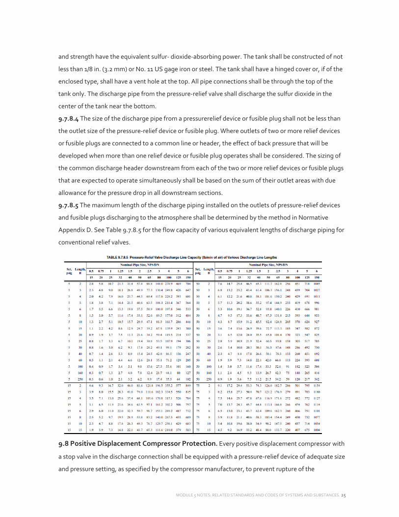
MODULE 5 NOTES: RELATED STANDARDS AND CODES OF SYSTEMS AND SUBSTANCES. 25
and strength have the equivalent sulfur‐ dioxide‐absorbing power. The tank shall be constructed of not
less than 1/8 in. (3.2 mm) or No. 11 US gage iron or steel. The tank shall have a hinged cover or, if of the
enclosed type, shall have a vent hole at the top. All pipe connections shall be through the top of the
tank only. The discharge pipe from the pressure‐relief valve shall discharge the sulfur dioxide in the
center of the tank near the bottom.
9.7.8.4 The size of the discharge pipe from a pressurerelief device or fusible plug shall not be less than
the outlet size of the pressure‐relief device or fusible plug. Where outlets of two or more relief devices
or fusible plugs are connected to a common line or header, the effect of back pressure that will be
developed when more than one relief device or fusible plug operates shall be considered. The sizing of
the common discharge header downstream from each of the two or more relief devices or fusible plugs
that are expected to operate simultaneously shall be based on the sum of their outlet areas with due
allowance for the pressure drop in all downstream sections.
9.7.8.5 The maximum length of the discharge piping installed on the outlets of pressure‐relief devices
and fusible plugs discharging to the atmosphere shall be determined by the method in Normative
Appendix D. See Table 9.7.8.5 for the flow capacity of various equivalent lengths of discharge piping for
conventional relief valves.
9.8 Positive Displacement Compressor Protection. Every positive displacement compressor with
a stop valve in the discharge connection shall be equipped with a pressure‐relief device of adequate size
and pressure setting, as specified by the compressor manufacturer, to prevent rupture of the

MODULE 5 NOTES: RELATED STANDARDS AND CODES OF SYSTEMS AND SUBSTANCES. 26
compressor or to prevent the pressure from increasing to more than 10% above the maximum
allowable working pressure of any other component located in the discharge line between the
compressor and the stop valve or in accordance with Section 9.7.5, whichever is larger. The pressure‐
relief device shall discharge into the low‐pressure side of the system or in accordance with Section
9.7.8.
Exception: Hermetic refrigerant motor‐compressors that are listed and have a displacement less than
or equal to 50 ft3/min (1.42 m3/min). The relief device(s) shall be sized based on compressor flow at the
following conditions:
a. Compressors in Single‐Stage Systems and High‐Stage Compressors of Other Systems: Flow shall be
calculated based on 50°F (10°C) saturated suction temperature at the compressor suction.
b. Low‐Stage or Booster Compressors in Compound Systems: For those compressors that are capable of
running only when discharging to the suction of a high‐stage compressor, flow shall be calculated
based on the saturated suction temperature equal to the design operating intermediate temperature.
c. Low‐Stage Compressors in Cascade Systems: For those compressors that are located in the lower‐
temperature stage(s) of cascade systems, flow shall be calculated based on the suction pressure being
equal to the pressure setpoint of the pressure‐relieving devices that protect the lowside of the stage
against overpressure.
Exceptions for (A), (B), and (C): The discharge capacity of the relief device is allowed to be the minimum
regulated flow rate of the compressor when all of the following conditions are met:
1. The compressor is equipped with capacity regulation.
2. Capacity regulation actuates to minimum flow at 90% of the pressure‐relief device setting.
3. A pressure‐limiting device is installed and set in accordance with the requirements of Section 9.9.
9.9 Pressure‐Limiting Devices
9.9.1 When Required. Pressure‐limiting devices shall be provided on all systems operating above
atmospheric pressure, except that a pressure‐limiting device is not required on any factory‐sealed
system containing less than 22 lb (10 kg) of Group A1 refrigerant that has been listed by an approved,
nationally recognized testing laboratory and is so identified.
9.9.2 Setting. When required by Section 9.9.1, the maximum setting to which a pressure‐limiting
device is capable of being readily set by use of the adjusting means provided shall not exceed the
design pressure of the highside of a system that is not protected by a pressure‐relief device or 90% of
the setting of the pressure‐relief device installed on the highside of a system. The pressure‐limiting
device shall stop the action of the pressure‐imposing element at a pressure no higher than this
maximum setting.
MODULE 5 NOTES: RELATED STANDARDS AND CODES OF SYSTEMS AND SUBSTANCES. 27
Exception: On systems using nonpositive displacement compressors, the maximum setting of the
pressurelimiting device is not required to be less than the design pressure of the highside of the system,
provided the pressure‐relief device is (a) located in the lowside,
(b) subject to lowside pressure, and (c) there is a permanent (unvalved) relief path between the highside
and the lowside of the system.
9.9.3 Connection. Pressure‐limiting devices shall be connected between the pressure‐imposing
element and any stop valve on the discharge side. There shall be no intervening stop valves in the line
leading to the pressure‐limiting device.
9.10 Refrigerant Piping, Valves, Fittings, and Related Parts
9.10.1 Refrigerant piping, valves, fittings, and related parts having a maximum internal or external
design pressure greater than 15 psig (103.4 kPa gage) shall be listed either individually or as part of an
assembly or a system by an approved, nationally recognized laboratory or shall comply with ASME
B31.58 where applicable.
9.10.2 Refrigerant Parts in Air Duct. Joints and all refrigerant‐ containing parts of a refrigerating
system located in an air duct carrying conditioned air to and from an occupied space shall be
constructed to withstand a temperature of 700°F (371°C) without leaking into the airstream.
9.11 Components Other Than Pressure Vessels and Piping
9.11.1 Every pressure‐containing component of a refrigerating system, other than pressure vessels,
piping, pressure gages, and control mechanisms, shall be listed either individually or as part of a
complete refrigerating system or a subassembly by an approved, nationally recognized testing
laboratory or shall be designed, constructed, and assembled to have an ultimate strength sufficient to
withstand three times the design pressure for which it is rated.
Exception: Water‐side components exempted from the rules of Section VIII of the ASME Boiler and
Pressure Vessel Code6 shall be designed, constructed, and assembled to have an ultimate strength
sufficient to withstand 150 psig (1034 kPa) or two times the design pressure for which it is rated,
whichever is greater.
9.11.2 Liquid‐level‐gage glass columns shall have automatic closing shutoff valves. All such glass
columns shall be protected against external damage and properly supported.
Exception: Liquid‐level‐gage glasses of the bull’s‐eye type
9.11.3 When a pressure gage is permanently installed on the highside of a refrigerating system, its dial
shall be graduated to at least 1.2 times the design pressure.
9.11.4 Liquid receivers, if used, or parts of a system designed to receive the refrigerant charge during
pumpdown shall have sufficient capacity to receive the pumpdown charge.

MODULE 5 NOTES: RELATED STANDARDS AND CODES OF SYSTEMS AND SUBSTANCES. 28
The liquid shall not occupy more than 90% of the volume when the temperature of the refrigerant is
90°F (32°C).
Note: The receiver volume is not required to contain the total system charge but is required to contain
the amount being transferred. If the environmental temperature is expected to rise above 122°F (50°C),
the designer shall account for the specific expansion characteristics of the refrigerant.
9.12 Service Provisions
9.12.1 All serviceable components of refrigerating systems shall be provided with safe access.
9.12.2 Condensing units or compressor units with enclosures shall be provided with safe access without
the need to climb over or remove any obstacles or to use portable access devices to get to the
equipment.
9.12.3 All systems shall have provisions to handle the refrigerant charge for service purposes. When
required, there shall be liquid and vapor transfer valves, a transfer compressor or pump, and refrigerant
storage tanks or appropriate valved connections for removal by a reclaim, recycle, or recovery device.
9.12.4 Systems containing more than 6.6 lb (3 kg) of refrigerant shall have stop valves installed at
a. the suction inlet of each compressor, compressor unit, or condensing unit;
b. the discharge of each compressor, compressor unit, or condensing unit; and
c. the outlet of each liquid receiver.
Exception: Systems that have a refrigerant pumpout function capable of storing the entire refrigerant
charge, or are equipped with the provisions for pumpout of the refrigerant, or self‐contained systems
9.12.5 Systems containing more than 110 lb (50 kg) of refrigerant shall have stop valves installed at
a. the suction inlet of each compressor, compressor unit, or condensing unit;
b. the discharge outlet of each compressor, compressor unit, or condensing unit;
c. the inlet of each liquid receiver, except for self‐contained systems or where the receiver is an integral
part of the condenser or condensing unit;
d. the outlet of each liquid receiver; and
e. the inlets and outlets of condensers when more than one condenser is used in parallel in the system.
Exception: Systems that have a refrigerant pumpout function capable of storing the entire refrigerant
charge, or are equipped with the provisions for pumpout of the refrigerant, or self‐contained systems
9.12.6 Stop valves shall be suitably labeled if the components to and from which the valve regulates
flow are not in view at the valve location. Valves or piping adjacent to the valves shall be identified in
accordance with ANSI A13.1.9
When numbers are used to label the valves, there shall be a key to the numbers located within sight of
the valves with letters at least 0.5 in. (12.7 mm) high.
9.13 Fabrication

MODULE 5 NOTES: RELATED STANDARDS AND CODES OF SYSTEMS AND SUBSTANCES. 29
9.13.1 The following are requirements for unprotected refrigerant‐containing copper pipe or tubing:
a. Copper tubing used for refrigerant piping shall conform to one of the following ASTM specifications:
B8810 types K or L or B280.11 Where ASTM B6812 and B7513 tubing is
used, the tube wall thickness shall meet or exceed the requirements of ASTM B28011 for the given
outside diameter.
b. Copper tube shall be connected by brazed joints, soldered joints, or compression fittings.
c. For Group A2, A3, B1, B2, and B3 refrigerants, protective metal enclosures shall be provided for
annealed copper tube erected on the premises.
Exception: No enclosures shall be required for connections between a condensing unit and the nearest
protected riser if such connections are not longer than 6.6 ft (2 m) in length.
9.13.2 Joints on refrigerant‐containing copper tube that are made by the addition of filler metal shall be
brazed.
Exception: A1 refrigerants
9.14 Factory Tests
9.14.1 All refrigerant‐containing parts or unit systems shall be tested and proved tight by the
manufacturer at not less than the design pressure for which they are rated. Pressure vessels shall be
tested in accordance with Section 9.3.
9.14.1.1 TESTING PROCEDURE. Tests shall be performed with dry nitrogen or another nonflammable,
nonreactive, dried gas. Oxygen, air, or mixtures containing them shall not be used. The means used to
build up the test pressure shall have either a pressure‐limiting device or a pressure‐reducing device and
a gage on the outlet side. The pressure‐relief device shall be set above the test pressure but low enough
to prevent permanent deformation of the system’s components.
Exceptions:
1. Mixtures of dry nitrogen, inert gases, nonflammable refrigerants allowed for factory tests.
2. Mixtures of dry nitrogen, inert gases, or a combination of them with flammable refrigerants in
concentrations not exceeding the lesser of a refrigerant weight fraction (mass fraction) of 5% or 25% of
the LFL are allowed for factory tests.
3. Compressed air without added refrigerant is allowed for factory tests, provided the system is
subsequently evacuated to less than 1000 microns (132 Pa) before charging with refrigerant. The
required evacuation level is atmospheric pressure for systems using R‐718 (water) or R‐744 (carbon
dioxide) as the refrigerant.
9.14.2 The test pressure applied to the highside of each factory‐ assembled refrigerating system shall
be at least equal to the design pressure of the highside. The test pressure applied to the lowside of each
factory‐assembled refrigerating system shall be at least equal to the design pressure of the lowside.
MODULE 5 NOTES: RELATED STANDARDS AND CODES OF SYSTEMS AND SUBSTANCES. 30
The pressure test on the complete unit shall not be conducted at the lowside design pressure per
Section 9.2 unless the final assembly connections are made per ASME B31.5.8 In this case, parts shall be
individually tested by either the unit manufacturer or the manufacturer of the part at not less than the
highside design pressure.
9.14.3 Units with a design pressure of 15 psig (103.4 kPa gage) or less shall be tested at a pressure not
less than 1.33 times the design pressure and shall be proved leak‐tight at not less than the lowside
design pressure.
9.15 Nameplate. Each unit system and each separate condensing unit, compressor, or compressor unit
sold for field assembly in a refrigerating system shall carry a nameplate marked with the manufacturer’s
name, nationally registered trademark or trade name, identification number, design pressures, and
refrigerant for which it is designed. The refrigerant shall be designated by the refrigerant number (R
number) as shown in Table 4‐1 or 4‐2 of ASHRAE Standard 34.1
10. OPERATION ANDTESTING
10.1 Field Tests
10.1.1 Every refrigerant‐containing part of every system that is erected on the premises, except
compressors, condensers, evaporators, safety devices, pressure gages, control mechanisms, and
systems that are factory‐tested, shall be tested and proved tight after complete installation and before
operation.
The highside and lowside of each system shall be tested and proved tight at not less than the lower of
the design pressure or the setting of the pressure‐relief device protecting the highside or lowside of the
system, respectively.
10.1.2 Testing Procedure. Tests shall be performed with dry nitrogen or another nonflammable,
nonreactive, dried gas. Oxygen, air, or mixtures containing them shall not be used. The means used to
build up the test pressure shall have either
a pressure‐limiting device or a pressure‐reducing device and a gage on the outlet side. The pressure‐
relief device shall be set above the test pressure but low enough to prevent permanent deformation of
the system’s components.
Exceptions:
1. Mixtures of dry nitrogen, inert gases, or a combination of them with nonflammable refrigerants in
concentrations of a refrigerant weight fraction (mass fraction) not exceeding 5% are allowed for tests.
2. Mixtures of dry nitrogen, inert gases, or a combination of them with flammable refrigerants in
concentrations not exceeding the lesser of a refrigerant weight fraction (mass fraction) of 5% or 25% of
the
LFL are allowed for tests.

MODULE 5 NOTES: RELATED STANDARDS AND CODES OF SYSTEMS AND SUBSTANCES. 31
3. Compressed air without added refrigerant is allowed for tests, provided the system is subsequently
evacuated to less than 1000 microns (132 Pa) before charging with refrigerant. The required evacuation
level is atmospheric pressure for systems using R‐718 (water) or R‐744 (carbon dioxide) as the
refrigerant.
4. Systems erected on the premises using Group A1 refrigerant and with copper tubing not exceeding
0.62 in. (16 mm) outside diameter shall be tested by means of the refrigerant charged into the system
at the saturated vapor pressure of the refrigerant at
68°F (20°C) minimum.
10.2 Declaration. A dated declaration of test shall be provided for all systems containing 55 lb (25 kg) or
more of refrigerant. The declaration shall give the name of the refrigerant and the field test pressure
applied to the highside and the lowside of the system. The declaration of test shall be signed by the
installer and, if an inspector is present at the tests, the inspector shall also sign the declaration. When
requested, copies of this declaration shall be furnished to the AHJ.

MODULE 5 NOTES: RELATED STANDARDS AND CODES OF SYSTEMS AND SUBSTANCES. 32
ASHRAE 34: DESIGNATION AND SAFETY CLASSIFICATION OF REFRIGERANTS
1. PURPOSE
This standard is intended to establish a simple means of referring to common refrigerants instead of
using the chemical name, formula, or trade name. It establishes a uniform system for assigning
reference numbers, safety classifications, and refrigerant concentration limits to refrigerants. The
standard also identifies requirements to apply for designations and safety classifications for refrigerants
and to determine refrigerant concentration limits.
2. SCOPE
This standard provides an unambiguous system for numbering refrigerants and assigning composition‐
designating prefixes for refrigerants. Safety classifications based on toxicity and flammability data are
included along with refrigerant concentration limits for the refrigerants.
This standard does not imply endorsement or concurrence that individual refrigerant blends are
suitable for any particular application.
4. NUMBERING OF REFRIGERANTS
An identifying number shall be assigned to each refrigerant. Reference C1 in Informative Appendix C
provides background on the need for a standard refrigerant nomenclature. Assigned numbers are
shown in Tables 4‐1 and 4‐2.
Section of Table 4.1
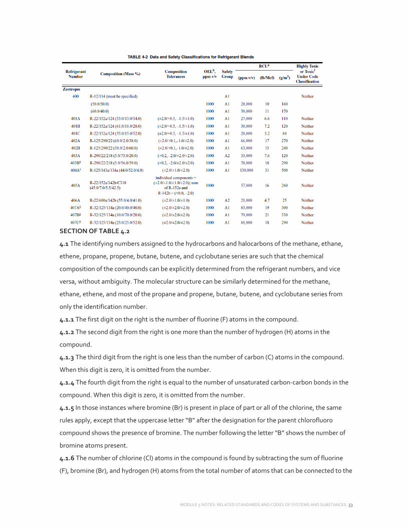
MODULE 5 NOTES: RELATED STANDARDS AND CODES OF SYSTEMS AND SUBSTANCES. 33
SECTION OF TABLE 4.2
4.1 The identifying numbers assigned to the hydrocarbons and halocarbons of the methane, ethane,
ethene, propane, propene, butane, butene, and cyclobutane series are such that the chemical
composition of the compounds can be explicitly determined from the refrigerant numbers, and vice
versa, without ambiguity. The molecular structure can be similarly determined for the methane,
ethane, ethene, and most of the propane and propene, butane, butene, and cyclobutane series from
only the identification number.
4.1.1 The first digit on the right is the number of fluorine (F) atoms in the compound.
4.1.2 The second digit from the right is one more than the number of hydrogen (H) atoms in the
compound.
4.1.3 The third digit from the right is one less than the number of carbon (C) atoms in the compound.
When this digit is zero, it is omitted from the number.
4.1.4 The fourth digit from the right is equal to the number of unsaturated carbon‐carbon bonds in the
compound. When this digit is zero, it is omitted from the number.
4.1.5 In those instances where bromine (Br) is present in place of part or all of the chlorine, the same
rules apply, except that the uppercase letter “B” after the designation for the parent chlorofluoro
compound shows the presence of bromine. The number following the letter “B” shows the number of
bromine atoms present.
4.1.6 The number of chlorine (Cl) atoms in the compound is found by subtracting the sum of fluorine
(F), bromine (Br), and hydrogen (H) atoms from the total number of atoms that can be connected to the

MODULE 5 NOTES: RELATED STANDARDS AND CODES OF SYSTEMS AND SUBSTANCES. 34
carbon (C) atoms. For saturated refrigerants, this number is 2n + 2, where n is the number of carbon
atoms. The number is 2n for mono‐unsaturated and cyclic‐saturated refrigerants.
4.1.7 The carbon atoms shall be numbered sequentially, in order of appearance, with the number “1”
assigned to the end carbon with the greatest number of hydrogen substituents (i.e., number of
halogenated atoms substituted for hydrogen on the alkane end carbon atoms). In the case where both
end carbons of a saturated compound contain the same number of (but different) halogen atoms, the
number “1” shall be assigned to the end carbon, defined as having the largest number of bromine, then
chlorine, then fluorine, and then iodine atoms. If the compound is an olefin, then the end carbon
nearest to the double bond will be assigned the number “1,” as the presence of a double bond in the
backbone of the molecule has priority over substituent groups on the molecule.
4.1.8 In the case of isomers in the ethane series, each has the same number, with the most symmetrical
one indicated by the number alone. As the isomers become more and more unsymmetrical,
successive lowercase letters (e.g., “a,” “b,” or “c”) are appended. Symmetry is determined by
first summing the atomic mass of the halogen and hydrogen atoms attached to each carbon
atom. One sum is subtracted from the other; the smaller the absolute value of the difference,
the more symmetrical the isomer.
4.1.9 In the case of isomers in the propane series, each has the same number, with the isomers
distinguished by two appended lowercase letters. The first appended letter indicates the substitution
on the central carbon atom (C2):
‐ Cl x
‐ F y
‐ H z
For halogenated derivatives of cyclopropane, the carbon atom with the largest sum of attached atomic
masses shall be considered the central carbon atom; for these compounds, the first appended letter is
omitted. The second appended letter indicates the relative symmetry of the substituents on the end
carbon atoms (C1 and C3). Symmetry is determined by first summing the atomic masses of the halogen
and hydrogen atoms attached to the C1 and C3 carbon atoms. One sum is subtracted from the other;
the smaller the absolute value of this difference, the more symmetrical the isomer. In contrast to the
ethane series, however, the most symmetrical isomer has a second appended letter of “a” (as opposed
to no appended letter for ethane isomers); increasingly asymmetrical isomers are assigned successive
letters. Appended letters are omitted when no isomers are possible, and the number alone represents
the molecular structure unequivocally; for example, CF3CF2CF3 is designated R‐218, not R‐218ca. An
example of this system is given in Informative Appendix A.

MODULE 5 NOTES: RELATED STANDARDS AND CODES OF SYSTEMS AND SUBSTANCES. 35
4.1.10 In the case of isomers of the propene series, each has the same number, with the isomers
distinguished by two appended lowercase letters. The first appended letter indicates the substitution
on the central carbon atom (C2):
—Cl x
—F y
—H z
The second letter designates the substitution on the terminal methylene carbon as defined for the
methylene carbon of the propane, consistent with the methodology described in
Section 4.1.9:
=CCl2 a
=CClF b
=CF2 c
=CHCl d
=CHF e
=CH2 f
In the case where stereoisomers can exist, the opposed (Entgegen or trans) isomer will be identified by
the suffix (E) and the same side (Zusamen or cis) isomer will be identified by the suffix (Z).
4.1.11 Extension to Compounds of Four Carbon Atoms.
Compounds are coded according to the above‐stated rules with the designation number followed by a
set of letters indicating structure. The number of unsaturated linkages is given in the fourth digit from
the right. When the number for a digit place exceeds nine, it is set off by dashes. Linear compounds are
lettered starting at one end, cyclic compounds from a side group, or, if none, from a carbon in the ring
as described in Section 4.1.9. Carbon atoms with two hydrogens or halogens are lettered as in Section
4.1.9. Carbon atoms with three hydrogen or halogen atom substituents are lettered as shown below:
–CCl3 j
–CCl2F k
–CClF2 l
–CF3 m
–CHCl2 n
–CH2Cl o
–CHF2 p
–CH2F q
–CHClF r
–CH3 s

MODULE 5 NOTES: RELATED STANDARDS AND CODES OF SYSTEMS AND SUBSTANCES. 36
Only as many letters are used as are required to completely define the compound when taken with the
empirical structure given by the numerical designation. It is understood that no branching occurs in the
remaining structure. After the starting point, a side group(s) is/are given its/their letter(s) before the
backbone substituent (if any). When two or more lettering sequences may be applied, that with the
fewest letters and first alphabetical sequence is used.
4.1.12 Bromine‐containing, propane‐series isomers cannot be uniquely designated by this system.
4.2 For cyclic derivatives, the letter “C” is used before the identifying refrigerant numbers.
4.3 Ether‐based refrigerants shall be designated with the prefix “E” (for ethers) immediately preceding
the number. Except for the following differences, the root number designations for the hydrocarbon
atoms shall be determined according to the current standard for hydrocarbon nomenclature (see
Section 4.1).
4.3.1 Two‐carbon, dimethyl ethers require no further suffixes, as the presence of the “E” prefix provides
an unambiguous description.
4.3.2 Straight‐chain, three‐carbon ethers require the agreement of the hydrocarbon ordering in Section
4.1.7.
4.3.2.1 The position(s) of the ether oxygen(s) shall be given by the carbons to which they are first
encountered. An additional integer identifying the first carbon to which the ether oxygen is attached
will be appended to the suffix letters.
4.3.2.2 In the case of otherwise symmetric hydrocarbon structures, the ether oxygen shall appear in the
earliest sequential position.
4.3.2.3 Even in those cases where only a single propane isomer exists for the hydrocarbon portion of
the ether structure, such as CF3‐O‐CF2‐CF3, the suffix letters described in
Section 4.1.9 shall be retained. In this cited example, the correct designation shall be R‐E218ca1.
4.3.2.4 Structures containing two interspersed oxygen atoms, di‐ethers, shall be designated with two
following integers to designate the positions of the ether oxygens.
4.3.3 For cyclic ethers carrying both the C‐” and “E‐” prefixes, the “C” shall precede the “E,” as “CE,” to
designate cyclic ethers.
For four‐membered cyclic ethers, including three carbon and one ether oxygen atom, the root number
designations for the hydrocarbon atoms shall be constructed according to the current standard for
hydrocarbon nomenclature (Section 4.1).
4.4 Blends shall be identified by the designations assigned in this standard. Blends without assigned
designations shall be identified by their compositions, listing the components in order of increasing
normal boiling points separated by slashes, for example, R‐32/134a for a blend of R‐32 and R‐ 134a.
Specific formulations shall be further identified by appending the corresponding mass fractions

MODULE 5 NOTES: RELATED STANDARDS AND CODES OF SYSTEMS AND SUBSTANCES. 37
expressed as percentages to one decimal place and enclosing them in parentheses, for example, R‐
32/134a (30.0/70.0). No component shall be permitted at less than 0.6% m/m nominal. When
formulation tolerances are relevant to the discussion, the corresponding tolerances shall be appended
in a second set of parentheses, for example, R‐32/125/134a (30.0/10.0/60.0) (+1.0,–2.0/±2.0/±2.0) for a
blend of R‐32, R‐125, and R‐134a with nominal mass fractions of 30.0%, 10.0%, and 60.0%, respectively,
and mass fractions of 28.0% to 31.0%, 8.0% to 12.0%, and 58.0% to 62.0% with tolerances,
respectively.
4.4.1 Designation. Zeotropic blends shall be assigned an identifying number in the 400 series.
Azeotropes shall be assigned an identifying number in the 500 series. To differentiate among blends
having the same components with different proportions (% m/m), an uppercase letter shall be added as
a suffix in serial order of assignment. An example of a zoetrope would be R‐401A and an example of an
azeotrope would be R‐508A.
4.4.2 Composition Tolerances. Blends shall have tolerances specified for individual components.
Those tolerances shall be specified to the nearest 0.1% m/m. The maximum tolerance above or below
the nominal shall not exceed 2.0% m/m. The tolerance above or below the nominal shall not be less
than
0.1% m/m. The difference between the highest and the lowest tolerances shall not exceed one‐half of
the nominal component composition.
4.5 Miscellaneous organic compounds shall be assigned numbers in the 600 series in decadal groups, as
outlined in Table 4‐1, in serial order of designation within the groups. For the saturated hydrocarbons
with four to eight carbon atoms, the number assigned shall be 600 plus the number of carbon atoms
minus four. For example, butane is R‐600, pentane is R‐601, hexane is R‐602, heptane is R‐603, and
octane is R‐
604. The straight‐chain or “normal” hydrocarbon has no suffix. For isomers of the hydrocarbons with
four to eight carbon atoms, the lower‐case letters “a,” “b,” “c,” etc., are appended to isomers according
to the group(s) attached to the longest carbon chain as indicated below. For example, R‐601a is
assigned for 2‐methylbutane (isopentane) and R‐601b would be assigned for 2,2‐dimethylpropane
(neopentane).
Attached Group(S) Suffix none (straight chain) No suffix
2‐methyl‐ a
2,2‐dimethyl‐ b
3‐methyl‐ c
2,3‐dimethyl‐ d
3,3‐dimethyl‐ e

MODULE 5 NOTES: RELATED STANDARDS AND CODES OF SYSTEMS AND SUBSTANCES. 38
4.6 Inorganic compounds shall be assigned numbers in the 700 and 7000 series.
4.6.1 For compounds with relative molecular masses less than 100, the number shall be the sum of 700
and the relative molecular mass, rounded to the nearest integer.
4.6.2 For compounds with relative molecular masses equal to or greater than 100, the number shall be
the sum of 7000 and the relative molecular mass, rounded to the nearest integer.
4.6.3 When two or more inorganic refrigerants have the same relative molecular masses, uppercase
letters (i.e., “A,” “B,” “C,” etc.) shall be added, in serial order of designation, to distinguish among them.
5. DESIGNATION
5.1 General. This section provides guidance on prefixes for refrigerants to improve uniformity in order
to promote understanding. Both technical and nontechnical designations are provided to be selected
based on the nature and audience of the use.
5.2 Identification. Refrigerants shall be identified in accordance with Section 5.2.1, 5.2.2, or 5.2.3.
Section 5.2.1 shall be used in technical publications (for international uniformity and to preserve
archival consistency), on equipment nameplates, and in specifications. Section 5.2.2 can be used for
single component halocarbon refrigerants, where distinction between the presence or absence of
chlorine or bromine is pertinent. Composition designation may be appropriate for nontechnical, public,
and regulatory communications addressing compounds having environmental impact, such as ozone
depletion or global warming potential. Section 5.2.3 can be used, under the same circumstances as
Section 5.2.2, for blends (both azeotropic and zeotropic). Section 5.2.1 shall be used for miscellaneous
organic and inorganic compounds.
5.2.1 Technical Prefixes. The identifying number, as determined by Section 4, shall be preceded by the
letter “R,” the word “Refrigerant” (“Refrigerants” if more than one), or the manufacturer’s trademark or
trade name. Examples include: R 12, R‐12, Refrigerant 12, <Trade Name> 12, <Trade Name> R 12, R‐
500, R‐22/152a/114 (36.0/24.0/40.0), and R‐717. Trademarks and trade names shall not be used to
identify refrigerants on equipment nameplates or in specifications.
5.2.2 Composition‐Designating Prefixes. The identifying number, as determined by Section 4, shall be
prefixed by the letter “C” for carbon and preceded by “B,” “C,” or “F”—or a combination thereof in this
sequence—to signify the presence of bromine, chlorine, or fluorine, respectively. Compounds that also
contain hydrogen shall be further preceded by the letter “H” to signify the increased deterioration
potential before reaching the stratosphere.6 The compositional designating prefixes for ether shall
substitute an “E” for “C”, such that “HFE,” “HCFE,” and “CFE” refer to hydrofluoroethers,
hydrochlorofluoroethers, and chlorofluoroethers, respectively. The composition‐designating prefixes
for halogenated olefins shall be either “CFC,” “HCFC,” or “HFC” to refer to chlorofluorocarbon,
hydrochlorofluorocarbon, or hydrofluorocarbon, respectively, or with substitution of an “O” for the

MODULE 5 NOTES: RELATED STANDARDS AND CODES OF SYSTEMS AND SUBSTANCES. 39
carbon “C” as “CFO,” “HCFO,” or “HFO” to refer to chlorofluoro‐ olefin, hydrochlorofluoro‐olefin, or
hydrofluoroolefin, respectively. Halogenated olefins are a subset of halogenated organic (or carbon‐
containing) compounds having significantly shorter atmospheric lifetimes than their saturated
counterparts. Examples include CFC‐11, CFC‐12, BCFC‐12B1, BFC‐13B1, HCFC‐22, HC‐50, CFC‐113, CFC‐
114, CFC‐115, HCFC‐123, HCFC‐124, HFC‐125, HFC‐134a, HCFC‐141b, HCFC‐142b, HFC‐143a, HFC‐152a,
HC‐170, FC‐C318, and HFC‐1234yf or HFO‐1234yf.
5.2.3 Recognized blends (whether azeotropic, near azeotropic, or zeotropic) with assigned numbers can
be identified by linking the appropriate composition‐designating prefixes of individual components
(e.g., CFC/HFC‐500). Blends without assigned numbers can be identified using appropriate
composition‐ designating prefixes for each component (e.g., HCFC‐ 22/HFC‐152a/CFC‐114
[36.0/24.0/40.0]). Linked prefixes (e.g., HCFC/HFC/CFC‐22/152a/114 [36.0/24.0/40.0]) and prefixes
implying synthesized compositions (e.g., HCFC‐500 or HCFC‐22/152a/114 [36.0/24.0/40.0]) shall not be
used.
5.2.4 Composition‐designating prefixes should be used only in nontechnical publications in which the
potential for environmental impact is pertinent. The prefixes specified in Section 5.2.1, augmented if
necessary as indicated in Section 5.4, are preferred in other communications. Section 5.2.1 also may be
preferable for blends when the number of components makes composition‐designating prefixes
awkward, such as for those containing more than three individual components (e.g., in tetrary and
pentary blends).
5.3 Other prefixes, including “ACFC” and “HFA,” for “alternative to chlorofluorocarbons” and
“hydrofluorocarbon alternative,” respectively, shall not be used. Similarly, neither “FC” nor “CFC” shall
be used as universal prefixes to signify the fluorocarbon and chlorofluorocarbon families of refrigerants
(i.e., other than as stipulated in Section 5.2.2).
5.4 The convention specified in Section 5.2.1 can be complemented with pertinent data, when
appropriate, as a preferred alternative to composition‐designating prefixes in technical
communications. For example, the first mention of R‐12 in a discussion of the ozone‐depletion issue
might read, “R‐12, a CFC” or “R‐12 (ODP = 1.0).” Similarly, a document on the greenhouse effect could
cite “R‐22 (GWP = 0.34 relative to
R‐11),” and one on flammability might refer to “R‐152a (LFL = 4.1%).”
6. SAFETY GROUP CLASSIFICATIONS
6.1 Refrigerants shall be classified into safety groups according to the following criteria.
6.1.1 Classification. The safety classification shall consist of two alphanumeric characters (e.g., “A2” or
“B1”). The capital letter indicates the toxicity as determined by Section 6.1.2; the arabic numeral
denotes the flammability as determined by Section 6.1.3.
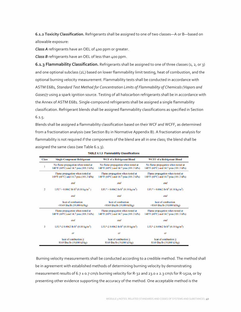
MODULE 5 NOTES: RELATED STANDARDS AND CODES OF SYSTEMS AND SUBSTANCES. 40
6.1.2 Toxicity Classification. Refrigerants shall be assigned to one of two classes—A or B—based on
allowable exposure:
Class A refrigerants have an OEL of 400 ppm or greater.
Class B refrigerants have an OEL of less than 400 ppm.
6.1.3 Flammability Classification. Refrigerants shall be assigned to one of three classes (1, 2, or 3)
and one optional subclass (2L) based on lower flammability limit testing, heat of combustion, and the
optional burning velocity measurement. Flammability tests shall be conducted in accordance with
ASTM E681, Standard Test Method for Concentration Limits of Flammability of Chemicals (Vapors and
Gases)7 using a spark ignition source. Testing of all halocarbon refrigerants shall be in accordance with
the Annex of ASTM E681. Single‐compound refrigerants shall be assigned a single flammability
classification. Refrigerant blends shall be assigned flammability classifications as specified in Section
6.1.5.
Blends shall be assigned a flammability classification based on their WCF and WCFF, as determined
from a fractionation analysis (see Section B2 in Normative Appendix B). A fractionation analysis for
flammability is not required if the components of the blend are all in one class; the blend shall be
assigned the same class (see Table 6.1.3).
Burning velocity measurements shall be conducted according to a credible method. The method shall
be in agreement with established methods of determining burning velocity by demonstrating
measurement results of 6.7 ± 0.7 cm/s burning velocity for R‐32 and 23.0 ± 2.3 cm/s for R‐152a, or by
presenting other evidence supporting the accuracy of the method. One acceptable method is the
MODULE 5 NOTES: RELATED STANDARDS AND CODES OF SYSTEMS AND SUBSTANCES. 41
vertical‐tube method as detailed by Jabbour and summarized by Jabbour and Clodic.8,9 Measurements
shall be conducted starting from the LFL to at least 125% of the stoichiometric concentration.
Measurements shall be done with increments of, at most, 10% of the stoichiometric concentration, and
each measurement shall be repeated at least two times. The burning velocity is the maximum value
obtained from a least‐squares fit to the measured data. The gas mixture shall be made by any method
that produces a blend of air/refrigerant that is accurate to ±0.1% in the test chamber. Dry air (less than
0.00015 g of water vapor per gram of dry air) containing 21.0% ± 0.1% O2 shall be used as the oxidant.
The flammable gas shall have a minimum purity of 99.5% by weight.
Note: Methods that have been used include (a) a pressurized mixture made by using partial pressure
and (b) quantitative flow methods like volumetric flowmeters and mass flow controllers fixing the ratio
of air and refrigerant.
6.1.3.1 Class 1
a. A single‐compound refrigerant shall be classified as Class 1 if the refrigerant does not show flame
propagation when tested in air at 140°F (60°C) and 14.7 psia (101.3 kPa).
b. The WCF of a refrigerant blend shall be classified as Class
1 if the WCF of the blend does not show flame propagation when tested in air at 140°F (60°C) and 14.7
psia (101.3 kPa).
c. The WCFF of a refrigerant blend shall be classified as Class 1 if the WCFF of the blend, as determined
from a fractionation analysis specified by Section B2 in Normative Appendix B, does not show flame
propagation when tested at 140°F(60.0°C) and 14.7 psia (101.3 kPa).
6.1.3.2 Class 2
a. A single‐compound refrigerant shall be classified as Class 2 if the refrigerant meets all three of the
following conditions:
1. Exhibits flame propagation when tested at 140°F (60°C) and 14.7 psia (101.3 kPa)
2. Has an LFL >0.0062 lb/ft3 (0.10 kg/m3) (see Section
3. Has a heat of combustion <8169 Btu/lb (19,000 kJ/kg) (see Section 6.1.3.5).
b. The WCF of a refrigerant blend shall be classified as Class 2 if it meets all three of the following
conditions:
1. Exhibits flame propagation when tested at 140°F (60°C) and 14.7 psia (101.3 kPa)
2. Has an LFL >0.0062 lb/ft3 (0.10 kg/m3) (see Section 6.1.3.4 if the WCF of the blend has no LFL at
73.4°F [23.0°C] and 14.7 psia [101.3 kPa])
3. Has a heat of combustion <8169 Btu/lb (19,000 kJ/kg) (see Section 6.1.3.5).
c. The WCFF of a refrigerant blend shall be classified as Class 2 if it meets all three of the following
conditions:

MODULE 5 NOTES: RELATED STANDARDS AND CODES OF SYSTEMS AND SUBSTANCES. 42
1. Exhibits flame propagation when tested at 140°F (60.0°C) and 14.7 psia (101.3 kPa)
2. Has an LFL >0.0062 lb/ft3 (0.10 kg/m3) (see Section 6.1.3.4 if the WCFF of the blend has no LFL at
73.4°F [23.0°C] and 14.7 psia [101.3 kPa])
3. Has a heat of combustion <8169 Btu/lb (19,000 kJ/kg) (see Section 6.1.3.5).
6.1.3.2.1 Subclass 2l (Optional). Refrigerants that meet the following additional condition: have a
maximum
6.1.3.3 Class 3
a. A single‐compound refrigerant shall be classified as Class 3 if the refrigerant meets both of the
following conditions:
1. Exhibits flame propagation when tested at 140°F (60°C) and 101.3 kPa (14.7 psia)
2. Has an LFL 0.0062 lb/ft3 (0.10 kg/m3) (see Section 6.1.3.4 if the refrigerant has no LFL at 73.4°F
[23.0°C] and 14.7 psia [101.3 kPa]) or it has a heat of combustion that is 8169 Btu/lb (19,000 kJ/kg)
b. The WCF of a refrigerant blend shall be classified as Class 3 if it meets both of the following
conditions:
1. Exhibits flame propagation when tested at 140°F (60°C) and 101.3 kPa (14.7 psia)
2. Has an LFL 0.0062 lb/ft3 (0.10 kg/m3) (see Section 6.1.3.4 if the refrigerant has no LFL at 73.4°F
[23.0°C] and 14.7 psia [101.3 kPa]) or it has a heat of combustion that is 8169 Btu/lb (19,000 kJ/kg)
c. The WCFF of a refrigerant blend shall be classified as Class 3 if it meets both of the following
conditions:
1. Exhibits flame propagation when tested at 60.0°C (140°F) and 101.3 kPa (14.7 psia) and
2. Has an LFL 0.0062 lb/ft3 (0.10 kg/m3) (see Section 6.1.3.4 if the refrigerant has no LFL at 73.4°F
[23.0°C] and 14.7 psia [101.3 kPa]) or it has a heat of combustion that is 8169 Btu/lb (19,000 kJ/kg)
6.1.3.4 For Class 2 or Class 3 refrigerants or refrigerant blends, the LFL shall be determined. For those
Class 2 or Class 3 refrigerants or refrigerant blends that show no flame propagation when tested at
73.4°F (23.0°C) and 14.7 psia (101.3 kPa) (i.e., no LFL), an elevated temperature flame limit at 140°F
(60°C) (ETFL60) shall be used in lieu of the LFL for determining their flammability classifications.
6.1.3.5 The heat of combustion shall be calculated for conditions of 77°F (25°C) and 14.7 psia (101.3
kPa).
a. For single‐component refrigerants, the heat of combustion shall be calculated. The heat of
combustion is the enthalpy of formation of the reactants (refrigerant and oxygen) minus the enthalpy
of formation of the products of reaction. Values for heats of formation are tabulated in several chemical
and physical property handbooks and databases.
In this standard, the heat of combustion is positive for exothermic reactions. Calculated values shall be
based on the complete combustion of one mole of refrigerant with enough oxygen for a stoichiometric
MODULE 5 NOTES: RELATED STANDARDS AND CODES OF SYSTEMS AND SUBSTANCES. 43
reaction. The reactants and the combustion products shall be assumed to be in the gas phase. The
combustion products shall be HF(g) (Note: not aqueous solution (aq)], CO2(g), [N2(g) or SO2(g) if
nitrogen or sulfur are part of the refrigerant’s molecular structure], HCl(g), and H2O(g).
If there is insufficient hydrogen (H) available for the formation of HF(g), HCl(g), and H2O(g), then the
formation of HF(g) takes preference over the formation of HCl(g), which takes preference over the
formation of H2O. If there is insufficient hydrogen available for all of the fluorine (F) to form HF(g), then
the remaining fluorine produces COF2(g) in preference of carbon (C) forming CO2. Any remaining
chloride (Cl) produces Cl2(g) (chlorine).
b. For refrigerant blends, the heat of combustion shall be calculated from a balanced stoichiometric
equation of all component refrigerants. This can be thought of conceptually as breaking the refrigerant
molecules into their constituent atoms and creating a hypothetical molecule with the same molar ratio
of total carbons, hydrogens, fluorines, etc. as is in the original blend. The hypothetical molecule would
then be treated as a pure refrigerant as in Section 6.1.3.5(a). The heat of formation for this hypothetical
molecule is the molar average of the heats of formation for the original blend of molecules.
Note: The molar percent or mass percent weighted average of the HOC of the pure component of a
blend produces incorrect results. For an example, see Informative Appendix F.
c. Heats of formation and heats of combustion are normally expressed as energy per mole (kJ/mol or
Btu/mol). For urposes of flammability classification under this standard, convert the heat of combustion
for a refrigerant from an energy per mole value to an energy per mass value (Btu/lb [kJ/kg]).
6.1.4 Matrix Diagram Of Safety Group Classification System. The toxicity and flammability
classifications described in Sections 6.1.1, 6.1.2, and 6.1.3 yield six separate safety group classifications
(A1, A2, A3, B1, B2, and B3) and two subclasses (A2L and B2L) for refrigerants. These classifications are
represented by the matrix shown in Figure 6.1.4.

MODULE 5 NOTES: RELATED STANDARDS AND CODES OF SYSTEMS AND SUBSTANCES. 44
6.1.5 Safety Classification Of Refrigerant Blends. Blends, whether zeotropic or azeotropic,
whose flammability and/or toxicity characteristics may change as the composition hanges during
fractionation, shall be assigned a safety group classification based on the worst case of fractionation.
This classification shall be determined according to the same criteria as that for a single‐compound
refrigerant.
For flammability, worst case of fractionation is defined as the composition during fractionation that
results in the highest concentration of the flammable component(s) in the vapor or liquid phase. For
toxicity, worst case of fractionation is defined as the composition during fractionation that results in the
highest concentration of the component(s) in the vapor or liquid phase for which the TLV‐TWA is less
than 400 ppm by volume. The TLV‐TWA for a specific blend composition shall be calculated from the
TLV‐TWA of the individual components (see Reference C‐4 of Informative Appendix C).
6.2 Other Standards. This classification is to be used in conjunction with other relevant safety
standards, such as ANSI/ASHRAE Standard 15, Safety Standard for Refrigeration Systems.10
7. REFRIGERANT CONCENTRATION LIMIT (RCL)
7.1 Single‐Compound Refrigerants. The RCL for each refrigerant shall be the lowest of the quantities
calculated in accordance with Sections 7.1.1, 7.1.2, and 7.1.3, using data as indicated in Section 7.3 and
adjusted in accordance with Section
7.4. Determination shall assume full vaporization with no removal by ventilation, dissolution, reaction,
or decomposition and complete mixing of the refrigerant in the space to which it is released.

MODULE 5 NOTES: RELATED STANDARDS AND CODES OF SYSTEMS AND SUBSTANCES. 45
7.1.1 Acute‐Toxicity Exposure Limit (Atel). The ATEL shall be the lowest of items (a) through (d) as
follows:
a. Mortality: 28.3% of the four‐hour LC50 for rats. If not determined, 28.3% of the four‐hour ALC for
rats. If neither has been determined, 0 ppm.
b. Cardiac Sensitization: One‐hundred percent of the NOEL for cardiac sensitization in unanesthetized
dogs. If not determined, 80% of the LOEL for cardiac sensitization in dogs. If neither has been
determined, 1000 ppm. The cardiac sensitization term is omitted from ATEL determination if the LC50
or ALC in (a) is less than 10,000 ppm by volume or if the refrigerant is found, by toxicological review, not
to cause cardiac sensitization.
c. Anesthetic or Central Nervous System Effects: Fifty percent of the ten‐minute EC50 in mice or rats for
loss of righting ability in a rotating apparatus, or 80% of NOEL in mice or rats for loss of righting ability
in a rotating apparatus, whichever is higher. If not determined, 50% of the LOEL for signs of any
anesthetic or CNS effect in rats during acute toxicity studies. If neither has been determined, 80% of
the NOEL for signs of any anesthetic or CNS effect in rats during an acute, subchronic, or chronic
toxicity study in which clinical signs are documented.
d. Other Escape‐Impairing Effects and Permanent Injury: Eighty percent of the lowest concentration, for
human exposures of 30 minutes, that is likely to impair ability to escape or to cause irreversible health
effects.
7.1.2 Oxygen Deprivation Limit (Odl). The ODL shall be 140,000 ppm by volume for locations with
altitudes at and below 3300 ft (1000 m) above sea level. At locations higher than 3300 ft (1000 m) but
below or equal to 4920 ft (1500 m), the ODL shall be 112,000 ppm, and at altitudes higher than 4920 ft
(1500 m), the ODL shall be 69,100 ppm (19.5% oxygen by volume).
7.1.3 Flammable Concentration Limit (Fcl). The FCL shall be calculated as 25% of the LFL determined
in accordance with Section 6.1.3.
7.2 Blends. The RCL for refrigerants comprising multiple compounds shall be determined by the
method in Section 7.1 except that individual parameter values in Section 7.1.1 (a) through (d) shall be
calculated as the mole‐weighted average, by composition of the nominal formulation, of the values for
the components. The calculation used to determine the ATEL and RCL of a refrigerant blend is
summarized in Informative
Appendix G. The calculation can also be performed using a computer program or spreadsheet.

MODULE 5 NOTES: RELATED STANDARDS AND CODES OF SYSTEMS AND SUBSTANCES. 46
STANDARD 90.2: ENERGY EFFICIENT DESIGN OF LOW‐RISE RESIDENTIAL BUILDINGS
1. PURPOSE The purpose of this standard is to provide minimum requirements for the energy‐
efficient design of residential buildings.
2. SCOPE
2.1 This standard provides minimum energy‐efficiency requirements for the design and construction of
a. new residential dwelling units and their systems and
b. where explicitly specified,
1. new portions of residential dwelling units and their systems and
2. new systems and equipment in existing dwelling units.
Note: There are no requirements in this standard that apply to new portions of residential dwelling
units and their systems, nor to new systems and equipment in existing dwelling units.
For the purposes of this standard, “residential dwelling units” include single‐family houses, multi‐family
structures (of three stories or fewer above grade), and modular houses.
This standard does not include “transient” housing, such as hotels, motels, nursing homes, jails, and
barracks, or manufactured housing.
2.2 This standard applies to the building envelope, heating equipment and systems, air‐conditioning
equipment and systems, domestic water‐heating equipment and systems, and provisions for overall
building design alternatives and trade‐offs.
2.3 This standard does not apply to
a. specific procedures for the operation, maintenance, and use of residential buildings;
b. portable products such as appliances and heaters; and
c. residential electric service or lighting requirements.
2.4 This standard shall not be used to abridge any safety, health, or environmental requirements.
4. COMPLIANCE
4.1 General. This standard provides different methods by which compliance can be determined for
low‐rise residential buildings—prescriptive or performance path methods (Sections
5, 6, and 7) or an annual energy cost method (Section 8).
5. BUILDING ENVELOPE REQUIREMENTS
5.1 Prescriptive Path
5.1.1 General. This section provides thermal performance requirements for the residential building
envelope that separates conditioned spaces from either exterior conditions or unconditioned spaces.
5.1.1.1 Single‐Family And Multi‐Family Compliance.

MODULE 5 NOTES: RELATED STANDARDS AND CODES OF SYSTEMS AND SUBSTANCES. 47
For the appropriate climate, the single‐family house and multi‐family structure envelope shall comply
with:
ANSI/ASHRAE Standard 90.2‐2007 5
a. the Prescriptive Path Method in accordance with Sections 5.2 through 5.11, or
b. the Envelope Performance Path Trade‐Off Method in accordance with Section 5.12, or
c. in cases where a systems analysis method of building design is desired, the requirements of Section 8
of this standard.
5.1.1.2 Climate. The climate for the requirements in Sections 5 and 8 shall be determined based on
Section 9.
5.2 Prescriptive Path Method. For one‐ and two‐family dwellings and multi‐family structures, the
thermal resistance of the cavity insulation and the thermal resistance of the continuous insulation
uninterrupted by framing, applied to the opaque building envelope components, shall be greater than
or equal to the minimum R‐values; the thermal transmittance of all assemblies shall be less than or
equal to the maximum U‐factors; and SHGC of all fenestration assemblies shall be less than or equal to
the maximum SHGC criteria, shown in Table 5.2
Exception High albedo roofs in Section 5.6.
5.2.1 Thermal Transmittance. The design thermal transmittance (U) shall be the variable used to
specify the requirements and demonstrate compliance for all doors and fenestration. All design U‐
factors are air‐to‐air, including interior and exterior air films. Calculation of design U‐factors shall be
done in accordance with the procedures in the ASHRAE Handbook—Fundamentals and account for
thermal bridges and anomalies.

MODULE 5 NOTES: RELATED STANDARDS AND CODES OF SYSTEMS AND SUBSTANCES. 48
5.2.2 Thermal Conductance. The thermal conductance (C) of all below‐grade envelope components
shall be the variable used to set the requirements and demonstrate compliance.
All C‐factors are surface‐to‐surface, excluding air films and the adjacent ground. Calculation of C‐
factors shall be done in accordance with the procedures in the ASHRAE Handbook—Fundamentals and
account for thermal bridges and anomalies.
5.3 Walls Next to Unconditioned Spaces. Unconditioned spaces shall include unconditioned
basements, unconditioned enclosed mechanical rooms, and unconditioned enclosed vestibules. Wood‐
and steel‐framed walls adjacent to unconditioned spaces shall comply with the insulation values
specified in the Table 5.2 category “Frame Adjacent to Unconditioned Spaces.” Mass walls adjacent to
unconditioned spaces shall comply with the “Above‐Grade Mass, Exterior Insulation” insulation values
specified in Table 5.2.
5.4 Mass Walls. Exterior insulation requirements shall apply when at least 50% of the required
insulation R‐value is on the exterior of, or integral to, the wall. Walls that do not meet this requirement
for insulation placement shall meet the requirements for interior insulation. The interior insulation case
shall apply when there are no exterior insulation requirements and wood or steel framing is used. When
an added R‐value of 3.4 or less is required, concrete block walls, in accordance with ASTM C90, with
cores filled with material having a maximum thermal conductivity of 0.44 Btu⋅in./h⋅ft2⋅°F, shall be
permitted to be used.
5.5 Envelope Assemblies Containing Steel Framing
5.5.1 Steel Stud Walls. The thermal transmittance of frame walls that contain steel stud assemblies
shall be calculated
5.5.2 Steel Framing In Ceiling/Roof. When the ceiling/ roof assembly contains cold‐formed steel
truss framing, the UR value to be used shall be determined by Equations 5‐3, 5‐ 4, or 5‐5. These
equations apply to cold‐formed steel truss roof framing spaced at 24 in. (609 mm) on‐center and where
the penetrations through the cavity insulation do not exceed three penetrations for each 4 ft (1220 mm)
length of the truss.
5.5.3 Steel Framing in Floors Over Unconditioned
Spaces. When the floor assembly contains cold‐formed steel framing, the value of Ufn used shall be
recalculated using a series of path procedures to correct for parallel path thermal bridging.
Exception When overall system‐tested Ufn values for steelframed floors from approved laboratories
are available (when such data are acceptable to the code official).
5.6 High Albedo Roofs. For roofs in climate zones 1, 2, or 3, where the exterior surface has either of
the following:

MODULE 5 NOTES: RELATED STANDARDS AND CODES OF SYSTEMS AND SUBSTANCES. 49
a. a minimum total solar reflectance of 0.65 when tested in accordance with ASTM C1549, E903, or
E1918 and a minimum thermal emittance of 0.75 when tested in accordance with ASTM E408 or C1371,
or
b. a minimum solar reflectance index (SRI) of 75 calculated in accordance with ASTM E1980 for medium
wind speed conditions, the R‐value of the proposed ceiling shall comply with the values in Table 5.6.1 or
the U‐factor of the proposed ceiling shall comply with the values in Table 5.6.2. The values for solar
reflectance and thermal emittance shall be determined by a laboratory accredited by a nationally
recognized accreditation organization, such as the Cool Roof Rating Council
CRRC‐1 Product Rating Program, and shall be labeled and certified by the manufacturer.
5.7 Floors
5.7.1 Slab‐On‐Grade Floors. All R‐values (°F∙ft2∙h/Btu) refer only to the insulation, excluding the
wall constructions and all other elements such as interior finish materials, the floor slab, exterior finish
materials, air films, and the adjacent ground. Perimeter insulation shall begin at the top surface of the
slab. The insulation length requirement may be satisfied by a combination of vertical and horizontal
sections provided they are continuous. Perimeter insulation is not required of areas of very heavy
termite infestation probability, as shown in Figure 5.6.

MODULE 5 NOTES: RELATED STANDARDS AND CODES OF SYSTEMS AND SUBSTANCES. 50
5.8 Doors. The requirements shall apply to all door assemblies that permit entry or exit from heated or
mechanically cooled spaces or both.
5.8.1 Opaque Portion of Non‐Wood Doors. The opaque portion of a non‐wood door assembly
shall not exceed the maximum U‐factor shown in Table 5.2.
5.8.2 Opaque Portion of Wood Doors. The opaque portion of a wood door assembly shall not
exceed a maximum U‐factor of 0.40 Btu/h⋅ft2⋅°F (5.678 W/m2∙K).
5.8.3 Glazed Portion of Any Door. The glazed portion of any door assembly shall not exceed a
maximum U‐factor as shown in the column entitled “fenestration” in Table 5.2.
5.9 Fenestration. The requirements shall apply to all operable or fixed glazed assemblies, including
windows, skylights, and glass doors, and shall not exceed the maximum U‐factors and SHGC values as
shown in Table 5.2. The U‐factor (U) of fenestration shall be determined in accordance with NFRC
100, and the SHGC of fenestration shall be determined in accordance with NFRC 200 by an accredited,
independent laboratory, and the fenestration shall be labeled and certified by the manufacturer.
Exceptions:
a. Skylight area, including frames, less than or equal to 1% of the total floor space utilized for living,
sleeping, eating, cooking, bathing, washing, and sanitation purposes is exempt from this requirement
provided the skylight U‐factor is less than 0.8.
b. Fenestration that can be thermally separated from the conditioned space (such as sunrooms,
solariums, and greenhouses) shall be excluded from the prescriptive

MODULE 5 NOTES: RELATED STANDARDS AND CODES OF SYSTEMS AND SUBSTANCES. 51
U‐factor, SHGC, and area requirements provided it is separated by envelope components that meet
this standard.
5.10 Air Leakage. The building envelope shall meet the provisions of Sections 5.10.1 through 5.10.4 or
shall comply with ANSI/ASHRAE Standard 119, Air Leakage Performance for Detached Single‐Family
Residential Buildings.
5.10.1 Windows And Doors. Window and door assemblies shall comply with Table 5.10.1.
5.10.2 Access Openings. Access openings in the building envelope, other than sliding and swinging
doors and windows, shall be sealed using weather stripping and be provided with a latch or some other
positive means of closure. The level of insulation provided with the access openings shall be equivalent
to that of the building envelope assembly in which it is installed.
5.10.3 Foundations. Foundation walls, crawlspace walls, and other building envelope walls below
grade shall have all cracks and the intersection of above‐grade construction assemblies with below‐
grade construction materials sealed.
5.10.4 Joints and Penetrations. Joints and penetrations in the building envelope that are sources of
air leakage shall be sealed with caulking, gasketing, weather stripping, or other materials compatible
with the construction materials, location, and anticipated conditions.
5.11 Water Vapor Retarders and Moisture Barriers.
5.11.1 A durable continuous moisture barrier at least 6 mil thick shall be placed over exposed soils in
crawlspaces and extend 1 ft (305 mm) up the crawlspace walls. Joints in the moisture barrier shall
overlap a minimum of 1 ft (305 mm).
5.11.2 A moisture barrier shall be installed beneath a heated slab.
5.12 Envelope Performance Path Trade‐Off Method.
The building envelope complies with this standard if the proposed building satisfies the provisions of
Section 5.2 and the envelope performance factor of the proposed building is less than or equal to the
annual heating and cooling energy costs for the envelope of the prescriptive path building. The annual
heating and cooling energy cost considers only the building envelope components. Heating,

MODULE 5 NOTES: RELATED STANDARDS AND CODES OF SYSTEMS AND SUBSTANCES. 52
ventilating, and air‐conditioning systems and equipment and service water heating shall be the same
for both the proposed building and the prescriptive.
6. HEATING, VENTILATING, AND AIR‐CONDITIONING (HVAC) SYSTEMS AND
EQUIPMENT
6.1 General. This section provides performance requirements for heating, ventilating, air‐
conditioning, and service water heating equipment for one‐ and two‐family houses and multi‐family
structures.
6.2 Heating, Ventilating, and Air‐Conditioning Systems And Equipment. This section shall
regulate only equipment using single‐phase electric power, air conditioners, and heat pumps with rated
cooling capacities less than 65,000 Btu/h (19 kW), warm air furnaces with rated heating capacities less
than 225,000 Btu/h (66 kW), boilers less than 300,000 Btu/h (88 kW) input, and heating‐only heat
pumps with rated heating capacities less than 65,000 Btu/h (19 kW).
6.3 Balancing. The air distribution system design, including outlet grilles, shall provide a means for
balancing the air distribution system unless the design procedure provides a system intended to
operate within ±10% of design air quantities.
6.4 Insulation For Ducts. All portions of the air distribution system installed in or on buildings for
heating and cooling shall be R‐8. When the mean outdoor dew‐point temperature in any month
exceeds 60°F (15°C), vapor retarders shall be installed on conditioned‐air supply ducts. Vapor retarders
shall have a water vapor permeance not exceeding 0.5 perm (0.003 μg/Pa⋅s⋅m2) when tested in
accordance with Procedure A in ASTM E96. Insulation is not required when the ducts are within the
conditioned space.
6.5 Insulation for Piping. HVAC system piping installed to serve buildings and within buildings shall
be thermally insulated in accordance with Table 6.5.
6.6 Ventilation and Combustion Air
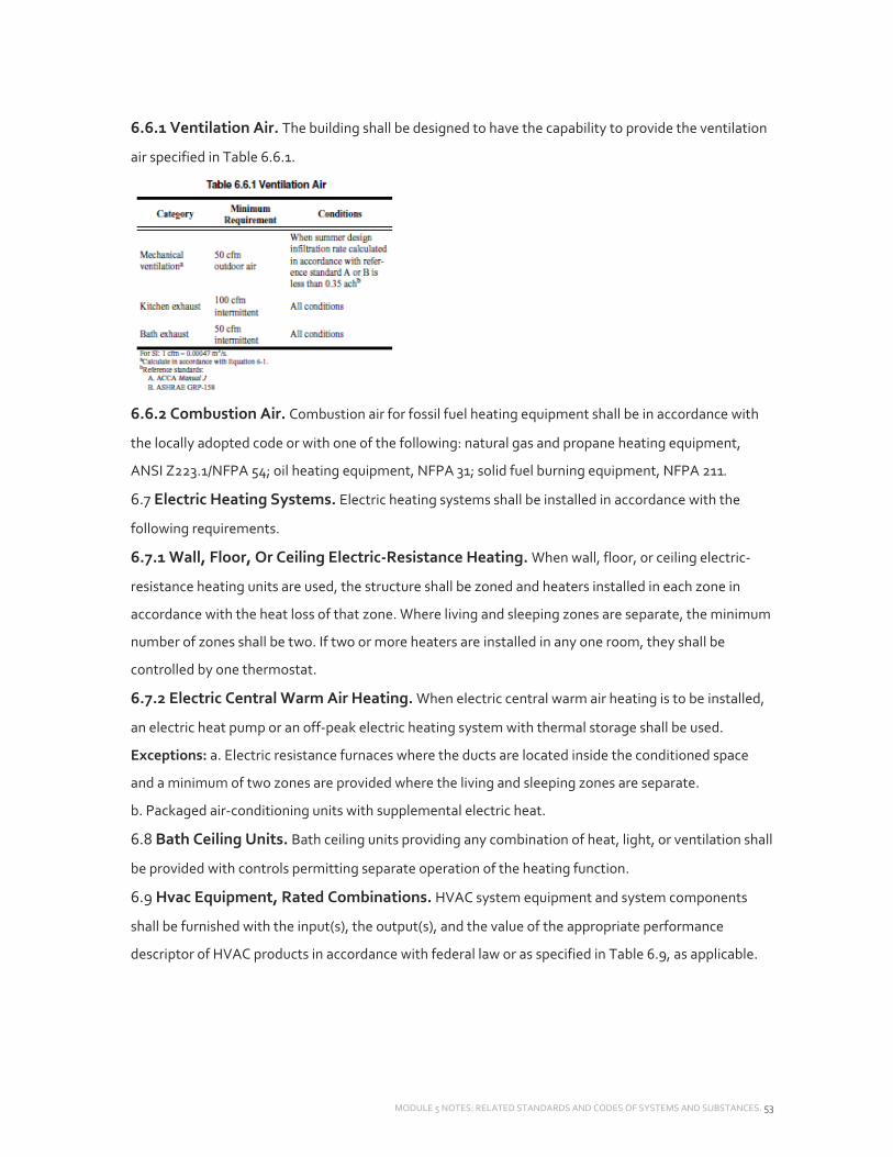
MODULE 5 NOTES: RELATED STANDARDS AND CODES OF SYSTEMS AND SUBSTANCES. 53
6.6.1 Ventilation Air. The building shall be designed to have the capability to provide the ventilation
air specified in Table 6.6.1.
6.6.2 Combustion Air. Combustion air for fossil fuel heating equipment shall be in accordance with
the locally adopted code or with one of the following: natural gas and propane heating equipment,
ANSI Z223.1/NFPA 54; oil heating equipment, NFPA 31; solid fuel burning equipment, NFPA 211.
6.7 Electric Heating Systems. Electric heating systems shall be installed in accordance with the
following requirements.
6.7.1 Wall, Floor, Or Ceiling Electric‐Resistance Heating. When wall, floor, or ceiling electric‐
resistance heating units are used, the structure shall be zoned and heaters installed in each zone in
accordance with the heat loss of that zone. Where living and sleeping zones are separate, the minimum
number of zones shall be two. If two or more heaters are installed in any one room, they shall be
controlled by one thermostat.
6.7.2 Electric Central Warm Air Heating. When electric central warm air heating is to be installed,
an electric heat pump or an off‐peak electric heating system with thermal storage shall be used.
Exceptions: a. Electric resistance furnaces where the ducts are located inside the conditioned space
and a minimum of two zones are provided where the living and sleeping zones are separate.
b. Packaged air‐conditioning units with supplemental electric heat.
6.8 Bath Ceiling Units. Bath ceiling units providing any combination of heat, light, or ventilation shall
be provided with controls permitting separate operation of the heating function.
6.9 Hvac Equipment, Rated Combinations. HVAC system equipment and system components
shall be furnished with the input(s), the output(s), and the value of the appropriate performance
descriptor of HVAC products in accordance with federal law or as specified in Table 6.9, as applicable.

MODULE 5 NOTES: RELATED STANDARDS AND CODES OF SYSTEMS AND SUBSTANCES. 54
These shall be based on newly produced equipment or components. Manufacturers’ recommended
maintenance instructions shall be furnished with and attached to the equipment.
The manufacturer of electric resistance heating equipment shall furnish full‐load energy input over the
range of voltages at which the equipment is intended to operate.
6.10 Controls
6.10.1 Temperature Control. Each system or each zone within a system shall be provided with at
least one thermostat capable of being set from 55°F (13°C) to 85°F (29°C) and capable of operating the
system’s heating and cooling. The thermostat or control system, or both, shall have an adjustable
deadband, the range of which includes a setting of 10°F (5.6°C) between heating and cooling when
automatic changeover is provided. Wall‐mounted temperature controls shall be mounted on an inside
wall.
6.10.2 Ventilation Control. Each mechanical ventilation system (supply or exhaust or both) shall be
equipped with a readily accessible switch or other means for shutoff. Manual or automatic dampers
installed for the purpose of isolating outside air intakes and exhausts from the air distribution system
shall be designed for tight shutoff.
6.10.3 Humidity Control
6.10.3.1 Heating. If additional energy‐consuming equipment is provided for adding moisture to
maintain specific selected relative humidities in spaces or zones, a humidistat shall be provided. This
device shall be capable of being set to prevent energy from being used to produce relative humidity
within the space above 30%.
6.10.3.2 Cooling. If additional energy‐consuming equipment is provided for reducing humidity, it shall
be equipped with controls capable of being set to prevent energy from being used to produce a relative
humidity within the space below 50% during periods of human occupancy and below 60% during
unoccupied periods.
6.10.3.3 Other Controls. When setback, zoned, humidity and cooling controls and equipment are
provided, they shall be designed and installed in accordance with Section 6.10.
7. SERVICE WATER HEATING

MODULE 5 NOTES: RELATED STANDARDS AND CODES OF SYSTEMS AND SUBSTANCES. 55
7.1 Application. Residential‐type water heaters, pool heaters, and unfired water heater storage tanks
shall meet the minimum performance requirements specified by federal law. Unfired storage water
heatingequipment shall have a heat loss through the tank surface area of less than 6.5 Btu/h⋅ft2.
7.2 Pump Operation. Circulating hot water systems shall be arranged so that the circulating pump(s)
can be turned off (automatically or manually) when the hot water system is not in operation.
7.3 Central Water Heating Equipment. Service water heating equipment (central systems) that
does not fall under the requirements for residential‐type service water heating equipment addressed in
Section 7.1 shall meet the applicable requirements for service water‐heating equipment found in
Standard 90.1.
7.4 Swimming Pools, Hot Tubs, and Spas
7.4.1 Pool Covers. Heated pools shall be equipped with a pool cover.
7.4.2 Covers. Outdoor pools deriving over 70% of the energy for heating (computed over an operating
season) from nondepletable sources or from recovery of energy that would otherwise be wasted shall
not be required to have pool covers.
7.4.3 Time Clock. Time clocks shall be installed so that the pump can be set to run in the off‐peak
electric demand period and can be set for the minimum time necessary to maintain the water in a clear
and sanitary condition in keeping with applicable health standards.
7.4.3.1 Pump. Pumps used to operate solar pool heating systems are not required to have time clocks
installed.
7.5 Heat Traps. Heat traps shall be installed on both the inlet and outlet of water heaters that have
vertical pipe risers connected to the top of the heater unless the water heater is equipped with an
integral heat trap or is part of a circulating system. The heat trap shall be installed as close as possible
to the inlet and the outlet fitting. The heat trap may be an arrangement of piping and fittings, such as
elbows, or a commercially available heat trap that prevents the thermosiphoning of the hot water
during standby periods.
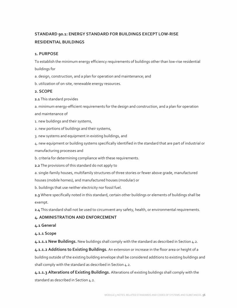
MODULE 5 NOTES: RELATED STANDARDS AND CODES OF SYSTEMS AND SUBSTANCES. 56
STANDARD 90.1: ENERGY STANDARD FOR BUILDINGS EXCEPT LOW‐RISE
RESIDENTIAL BUILDINGS
1. PURPOSE
To establish the minimum energy efficiency requirements of buildings other than low‐rise residential
buildings for
a. design, construction, and a plan for operation and maintenance; and
b. utilization of on‐site, renewable energy resources.
2. SCOPE
2.1 This standard provides
a. minimum energy‐efficient requirements for the design and construction, and a plan for operation
and maintenance of
1. new buildings and their systems,
2. new portions of buildings and their systems,
3. new systems and equipment in existing buildings, and
4. new equipment or building systems specifically identified in the standard that are part of industrial or
manufacturing processes and
b. criteria for determining compliance with these requirements.
2.2 The provisions of this standard do not apply to
a. single‐family houses, multifamily structures of three stories or fewer above grade, manufactured
houses (mobile homes), and manufactured houses (modular) or
b. buildings that use neither electricity nor fossil fuel.
2.3 Where specifically noted in this standard, certain other buildings or elements of buildings shall be
exempt.
2.4 This standard shall not be used to circumvent any safety, health, or environmental requirements.
4. ADMINISTRATION AND ENFORCEMENT
4.1 General
4.1.1 Scope
4.1.1.1 New Buildings. New buildings shall comply with the standard as described in Section 4.2.
4.1.1.2 Additions to Existing Buildings. An extension or increase in the floor area or height of a
building outside of the existing building envelope shall be considered additions to existing buildings and
shall comply with the standard as described in Section 4.2.
4.1.1.3 Alterations of Existing Buildings. Alterations of existing buildings shall comply with the
standard as described in Section 4.2.

MODULE 5 NOTES: RELATED STANDARDS AND CODES OF SYSTEMS AND SUBSTANCES. 57
4.1.1.4 Replacement of Portions of Existing Buildings.
Portions of a building envelope, heating, ventilating, airconditioning, service water heating, power,
lighting, and other systems and equipment that are being replaced shall be considered as alterations of
existing buildings and shall comply with the standard as described in Section 4.2.
4.1.1.5 Changes in Space Conditioning. Whenever unconditioned or semiheated spaces in a
building are converted to conditioned spaces, such conditioned spaces shall be brought into compliance
with all the applicable requirements of this standard that would apply to the building envelope, heating,
ventilating, air‐conditioning, service water heating, power, lighting, and other systems and equipment
of the space as if the building were new.
4.1.2 Administrative Requirements. Administrative requirements relating to permit requirements,
enforcement by the authority having jurisdiction, locally adopted energy standards, interpretations,
claims of exemption, and rights of appeal are specified by the authority having jurisdiction.
4.1.3 Alternative Materials, Methods of Construction, Or Design. The provisions of this
standard are not intended to prevent the use of any material, method of construction, design,
equipment, or building system not specifically prescribed herein.
4.1.4 Validity. If any term, part, provision, section, paragraph, subdivision, table, chart, or referenced
standard of this standard shall be held unconstitutional, invalid, or ineffective, in whole or in part, such
determination shall not be deemed to invalidate any remaining term, part, provision, section,
paragraph, subdivision, table, chart, or referenced standard of this standard.
4.1.5 Other Laws. The provisions of this standard shall not be deemed to nullify any provisions of
local, state, or federal law. Where there is a conflict between a requirement of this standard and such
other law affecting construction of the building, precedence shall be determined by the authority
having jurisdiction.
4.1.6 Referenced Standards. The standards referenced in this standard and listed in Section 12 shall
be considered part of the requirements of this standard to the prescribed extent of such reference.
Where differences occur between the provision of this standard and referenced standards, the
provisions of this standard shall apply. Informative references are cited to acknowledge sources and are
not part of this standard.
4.1.7 Normative Appendices. The normative appendices to this standard are considered to be
integral parts of the mandatory requirements of this standard, which, for reasons of convenience, are
placed apart from all other normative elements.

MODULE 5 NOTES: RELATED STANDARDS AND CODES OF SYSTEMS AND SUBSTANCES. 58
4.1.8 Informative Appendices. The informative appendices to this standard and informative notes
located within this standard contain additional information and are not mandatory or part of this
standard.
4.2 Compliance
4.2.1 Compliance Paths
4.2.1.1 New Buildings. New buildings shall comply with either the provisions of Section 5, “Building
Envelope”; Section 6, “Heating, Ventilating, and Air Conditioning”; Section 7, “Service Water Heating”;
Section 8, “Power”; 9, “Lighting”; and Section 10, “Other Equipment” or Section 11, “Energy Cost
Budget Method.”
4.2.1.2 Additions to Existing Buildings. Additions to existing buildings shall comply with either the
provisions of Sections 5, 6, 7, 8, 9, and 10 or Section 11.
4.2.1.2.1 When an addition to an existing building cannot comply by itself, trade‐offs will be allowed by
modification to one or more of the existing components of the existing building. Modeling of the
modified components of the existing building and addition shall employ the procedures of Section 11;
the addition shall not increase the energy consumption of the existing building plus the addition
beyond the energy that would be consumed by the existing building plus the addition if the addition
alone did comply.
4.2.1.3 Alterations of Existing Buildings. Alterations of existing buildings shall comply with the
provisions of Sections 5, 6, 7, 8, 9, and 10, provided, however, that nothing in this standard shall require
compliance with any provision of this standard if such compliance will result in the increase of energy
consumption of the building.
Exceptions:
1. A building that has been specifically designated as historically significant by the adopting authority or
is listed in The National Register of Historic Places or has been determined to be eligible for listing by
the U.S. Secretary of the Interior need not comply with these requirements.
2. Where one or more components of an existing building or portions thereof are being replaced, the
annual energy consumption of the comprehensive design shall not be greater than the annual energy
consumption of a substantially identical design, using the same energy types, in which compliance with
the applicable requirements of Sections 5, 6, 7, 8, 9, and 10, as provided in Section 4.2.1.2,1, is verified
by a design professional by the use of any calculation methods acceptable to the authority having
jurisdiction.
4.2.2 Compliance Documentation

MODULE 5 NOTES: RELATED STANDARDS AND CODES OF SYSTEMS AND SUBSTANCES. 59
4.2.2.1 Construction Details. Compliance documents shall show all the pertinent data and features
of the building, equipment, and systems in sufficient detail to permit a determination of compliance by
the building official and to indicate compliance with the requirements of this standard.
4.2.2.2 Supplemental Information. Supplemental information necessary to verify compliance with
this standard, such as calculations, worksheets, compliance forms, vendor literature, or other data, shall
be made available when required by the building official.
4.2.2.3 Manuals. Operating and maintenance information shall be provided to the building owner.
This information shall include, but not be limited to, the information specified in Sections 6.7.2.2, 8.7.2,
and 9.7.2.2.
4.2.3 Labeling Of Material and Equipment. Materials and equipment shall be labeled in a manner
that will allow for a determination of their compliance with the applicable provisions of this standard.
4.2.4 Inspections. All building construction, additions, or alterations subject to the provisions of this
standard shall be subject to inspection by the building official, and all such work shall remain accessible
and exposed for inspection purposes until approved in accordance with the procedures specified by the
building official. Items for inspection include at least the following:
a. Wall insulation after the insulation and vapor retarder are in place but before concealment
b. Roof/ceiling insulation after roof/insulation is in place but before concealment
c. Slab/foundation wall after slab/foundation insulation is in place but before concealment
d. Fenestration after all glazing materials are in place
e. Continuous air barrier after installation but before concealment
f. Mechanical systems and equipment and insulation after installation but before concealment
g. Electrical equipment and systems after installation but before concealment
5. BUILDING ENVELOPE
5.1 General
5.1.1 Scope. Section 5 specifies requirements for the building envelope.
5.1.2 Space‐Conditioning Categories
5.1.2.1 Separate exterior building envelope requirements are specified for each of three categories of
conditioned space: (a) nonresidential conditioned space, (b) residential conditioned space, and (c)
semiheated space.
5.1.2.2 The minimum skylight area requirements in Section 5.5.4.2.3 are also specified for
unconditioned spaces.

MODULE 5 NOTES: RELATED STANDARDS AND CODES OF SYSTEMS AND SUBSTANCES. 60
5.1.2.3 Spaces shall be assumed to be conditioned spaces and shall comply with the requirements for
conditioned spaces at the time of construction, regardless of whether mechanical or electrical
equipment is included in the building permit application or installed at that time.
5.1.2.4 In Climate Zones 3 through 8, a space may be designated as either a semiheated space or an
unconditioned space only if approved by the building official.
5.1.3 Envelope Alterations. Alterations to the building envelope shall comply with the requirements of
Section 5 for insulation, air leakage, and fenestration applicable to those specific portions of the
building that are being altered.
Exceptions: The following alterations need not comply with these requirements, provided such
alterations will not increase the energy usage of the building:
1. Installation of storm windows or glazing panels over existing glazing, provided the storm window or
glazing panel contains a low‐emissivity coating. However, a low‐emissivity coating is not required
where the existing glazing already has a low‐emissivity coating. Installation is permitted to be either on
the inside or outside of the existing glazing.
2. Replacement of glazing in existing sash and frame, provided the U‐factor and SHGC will be equal to
or lower than before the glass replacement.
3. Alterations to roof/ceiling, wall, or floor cavities that are insulated to full depth with insulation having
a minimum nominal value of R‐0.02/mm.
4. Alterations to walls and floors, where the existing structure is without framing cavities and no new
framing cavities are created.
5. Roof recovering.
6. Removal and replacement of a roof membrane where there is existing roof insulation integral to or
below the roof deck
7. Replacement of existing doors that separate a conditioned space from the exterior shall not require
the installation of a vestibule or revolving door, provided that an existing vestibule that separates a
conditioned space from the exterior shall not be removed.
8. Replacement of existing fenestration, provided that the area of the replacement fenestration does
not exceed 25% of the total fenestration area of an existing building and that the U‐factor and SHGC
will be equal to or lower than before the fenestration replacement.
5.2 Compliance Paths
5.2.1 Compliance. For the appropriate climate, space‐conditioning category, and class of
construction, the building envelope shall comply with Section 5.1, “General”; Section 5.4, “Mandatory
Provisions”; Section 5.7, “Submittals”; Section 5.8, “Product Information and Installation
Requirements”; and either

MODULE 5 NOTES: RELATED STANDARDS AND CODES OF SYSTEMS AND SUBSTANCES. 61
a. Section 5.5, “Prescriptive Building Envelope Option,” provided that the fenestration area does not
exceed the maximum allowed by Section 5.5.4.2, or
b. Section 5.6, “Building Envelope Trade‐Off Option.”
5.2.2 Projects using the Energy Cost Budget Method (see Section 11 of this standard) must comply with
Section 5.4, the mandatory provisions of this section, as a portion of that compliance path.
5.3 Simplified Building (Not Used)
5.4 Mandatory Provisions
5.4.1 Insulation. Where insulation is required in Section 5.5 or 5.6, it shall comply with the
requirements found in Sections 5.8.1.1 through 5.8.1.10.
5.4.2 Fenestration and Doors. Procedures for determining fenestration and door performance are
described in Section 5.8.2. Product samples used for determining fenestration performance shall be
production line units or representative of units purchased by the consumer or contractor.
5.4.3 Air Leakage
5.4.3.1 Continuous Air Barrier. The entire building envelope shall be designed and constructed with
a continuous air barrier.
Exceptions:
1. Semiheated spaces in Climate Zones 1 through 6.
2. Single wythe concrete masonry buildings in Climate Zone 2B.
5.4.3.1.1 Air Barrier Design. The air barrier shall be designed and noted in the following manner:
a. All air barrier components of each building envelope assembly shall be clearly identified or otherwise
noted on construction documents.
b. The joints, interconnections, and penetrations of the air barrier components, including lighting
fixtures, shall be detailed or otherwise noted.
c. The continuous air barrier shall extend over all surfaces of the building envelope (at the lowest floor,
exterior walls, and ceiling or roof).
d. The continuous air barrier shall be designed to resist positive and negative pressures from wind, stack
effect, and mechanical ventilation.
5.4.3.1.2 Air Barrier Installation. The following areas of the continuous air barrier in the building
envelope shall be wrapped, sealed, caulked, gasketed, or taped in an approved manner to minimize air
leakage:
a. Joints around fenestration and door frames (both manufactured and site‐built)
b. Junctions between walls and floors, between walls at building corners, and between walls and roofs
or ceilings
c. Penetrations through the air barrier in building envelope roofs, walls, and floors

MODULE 5 NOTES: RELATED STANDARDS AND CODES OF SYSTEMS AND SUBSTANCES. 62
d. Building assemblies used as ducts or plenums
e. Joints, seams, connections between planes, and other changes in air barrier materials
5.4.3.1.3 Acceptable Materials And Assemblies. Continuous air barrier materials and assemblies
for the opaque building envelope shall comply with one of the following requirements:
a. Materials that have an air permeance not exceeding 0.02 L/s∙m2 under a pressure differential of 0.02
L/s∙m2 at 75 Pa when tested in accordance with ASTM E 2178. The following materials meet these
requirements:
1. Plywood—minimum 10 mm
2. Oriented strand board—minimum 10 mm
3. Extruded polystyrene insulation board—minimum 12 mm
4. Foil‐faced urethane insulation board—minimum 12 mm
5. Exterior gypsum sheathing or interior gypsum board—minimum 12 mm
6. Cement board—minimum 12 mm
7. Built‐up roofing membrane
8. Modified bituminous roof membrane
9. Fully adhered single‐ply roof membrane
10. A Portland cement/sand parge, stucco, or gypsum plaster—minimum 12 mm thick
11. Cast‐in‐place and precast concrete
12. Sheet metal
13. Closed‐cell 32 kg/m3 nominal density spray polyurethane foam—minimum 25 mm
b. Assemblies of materials and components (sealants, tapes, etc.) that have an average air leakage not
to exceed 0.2 L/ s∙m2 under a pressure differential of 0.2 L/s∙m2 at 75 Pa when tested in accordance with
ASTM E 2357, ASTM E 1677, ASTM E 1680, or ASTM E283. The following assemblies meet these
requirements:
1. Concrete masonry walls that are
(a) fully grouted, or
(b) painted to fill the pores.
5.4.3.2 Fenestration And Doors. Air leakage for fenestration and doors shall be determined in
accordance with AAMA/WDMA/CSA 101/I.S.2/A440, NFRC 400, or ASTM E283 as specified below. Air
leakage shall be determined by a laboratory accredited by a nationally recognized accreditation
organization, such as the National Fenestration Rating Council, and shall be labeled and certified by the
manufacturer. Air leakage shall not exceed
a. 18.3 m3/h∙m2 for glazed swinging entrance doors and revolving doors, tested at a pressure of at least
75 Pa in accordance with AAMA/WDMA/CSA 101/I.S.2/A440, NFRC 400, or ASTM E283;

MODULE 5 NOTES: RELATED STANDARDS AND CODES OF SYSTEMS AND SUBSTANCES. 63
b. 1.1 m3/h∙m2for curtainwall and storefront glazing, tested at a pressure of at least 75 Pa or higher in
accordance with NFRC 400 or ASTM E283;
c. 5.5 m3/h∙m2 for unit skylights having condensation weepage openings, tested at a pressure of at least
75 Pa in accordance with AAMA/WDMA/CSA 101/I.S.2/A440 or NFRC 400, or 9.1 m3/h∙m2tested at a
pressure of at least 300 Pa in accordance with AAMA/WDMA/CSA 101/I.S.2/A440;
d. 23.8 m3/h∙m2 for nonswinging doors intended for vehicular access and material transportation, with a
minimum opening rate of 0.81 m/s, tested at a pressure of at least 75 Pa or higher in accordance with
ANSI/DASMA 105, NFRC 400, or ASTM E283.
e. 7.3 m3/h∙m2 for other nonswinging opaque doors, glazed sectional garage doors, and upward acting
nonswinging glazed doors tested at a pressure of at least 75 Pa or higher in accordance with
ANSI/DASMA 105, NFRC 400, or ASTM E283; and
f. 3.7 m3/h∙m2 for all other products tested at a pressure of at least 75 Pa in accordance with
AAMA/WDMA/CSA 101/I.S.2/A440 or NFRC 400, or 5.5 m3/h∙m2 tested at a pressure of at least 300 Pa in
accordance with AAMA/ WDMA/CSA 101/I.S/A440.
Exceptions:
1. Field‐fabricated fenestration and doors
2. Metal coiling doors in semiheated spaces in Climate Zones 1 through 6
3. Products in buildings that comply with a whole building air leakage rate of 7.3 m3/h∙m2 under a
pressure differential of 2 L/s∙m2 at 75Pa when tested in accordance with ASTM E 779
5.4.3.3 Loading Dockweatherseals. In Climate Zones 4 through 8, cargo doors and loading dock
doors shall be equipped with weatherseals to restrict infiltration when vehicles are parked in the
doorway.
5.4.3.4 Vestibules. Building entrances that separate conditioned space from the exterior shall be
protected with an enclosed vestibule, with all doors opening into and out of the vestibule equipped with
self‐closing devices. Vestibules shall be designed so that in passing through the vestibule it is not
necessary for the interior and exterior doors to open at the same time. Interior and exterior doors shall
have a minimum distance between them of not less than 2.1m when in the closed position. The floor
area of each vestibule shall not exceed the greatest of 5 m2 or 2% of the gross conditioned floor area for
that level of the building. The exterior envelope of conditioned vestibules shall comply with the
requirements for a conditioned space. The interior and exterior envelope of unconditioned vestibules
shall comply with the requirements for a semiheated space.
Exceptions:
1. Building entrances with revolving doors
2. Doors not intended to be used as a building entrance
MODULE 5 NOTES: RELATED STANDARDS AND CODES OF SYSTEMS AND SUBSTANCES. 64
3. Doors opening directly from a dwelling unit
4. Building entrances in buildings located in Climate Zone 1 or 2
5. Building entrances in buildings that are located in Climate Zone 3, less than four stories above grade,
and less than 1000 m2 in gross conditioned floor area
6. Building entrances in buildings that are located in Climate Zone 4, 5, 6, 7, or 8 and are less than 100
m2 in gross conditioned floor area
7. Doors that open directly from a space that is less than 300 m2 in area and is separate from the
building entrance
8. Semiheated spaces.
9. Enclosed elevator lobbies for building entrances directly from parking garages.
5.4.3.4.1 Where vestibules are required under Section 5.4.3.4, for spaces having a gross conditioned
floor area for that level of the building of 4000 m2 and greater, and when the doors opening into and
out of the vestibule are equipped with automatic, electrically driven, self‐closing devices, the interior
and exterior doors shall have a minimum distance between them of not less than 4.8 m.
5.5 Prescriptive Building Envelope Option
5.5.1 For a conditioned space, the exterior building envelope shall comply with either the nonresidential
or residential requirements in Tables 5.5‐1 through 5.5‐8 for the appropriate climate.

MODULE 5 NOTES: RELATED STANDARDS AND CODES OF SYSTEMS AND SUBSTANCES. 65

MODULE 5 NOTES: RELATED STANDARDS AND CODES OF SYSTEMS AND SUBSTANCES. 66
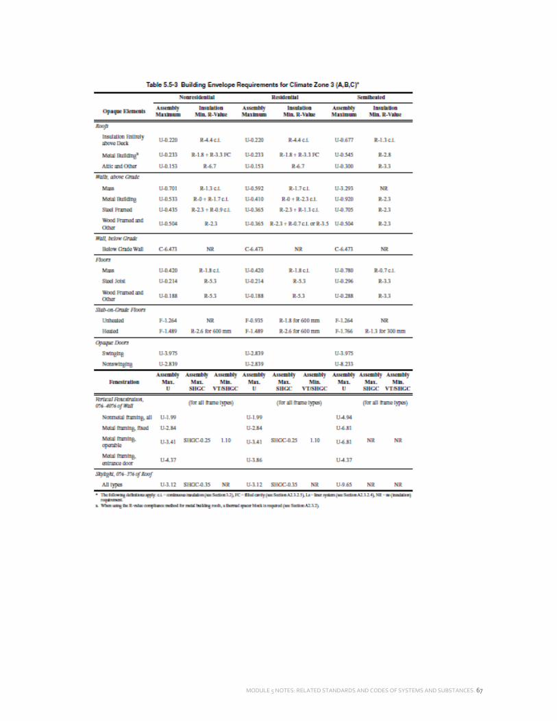
MODULE 5 NOTES: RELATED STANDARDS AND CODES OF SYSTEMS AND SUBSTANCES. 67

MODULE 5 NOTES: RELATED STANDARDS AND CODES OF SYSTEMS AND SUBSTANCES. 68

MODULE 5 NOTES: RELATED STANDARDS AND CODES OF SYSTEMS AND SUBSTANCES. 69

MODULE 5 NOTES: RELATED STANDARDS AND CODES OF SYSTEMS AND SUBSTANCES. 70

MODULE 5 NOTES: RELATED STANDARDS AND CODES OF SYSTEMS AND SUBSTANCES. 71

MODULE 5 NOTES: RELATED STANDARDS AND CODES OF SYSTEMS AND SUBSTANCES. 72
5.5.2 If a building contains any semiheated space or unconditioned space, then the semi‐exterior
building envelope shall comply with the requirements for semiheated space in Tables 5.5‐1 through 5.5‐
8 for the appropriate climate. (See Figure 5.5.2.)
5.5.3 Opaque Areas. For all opaque surfaces except doors, compliance shall be demonstrated by one of
the following two methods:
a. Minimum rated R‐values of insulation for the thermal resistance of the added insulation in framing
cavities and continuous insulation only. Specifications listed in Normative Appendix A for each class of
construction shall be used to determine compliance.
b. Maximum U‐factor, C‐factor, or F‐factor for the entire assembly. The values for typical construction
assemblies listed in Normative Appendix A shall be used to determine compliance.
Exceptions:
1. For assemblies significantly different than those in Appendix A, calculations shall be performed in
accordance with the procedures required in Appendix A.

MODULE 5 NOTES: RELATED STANDARDS AND CODES OF SYSTEMS AND SUBSTANCES. 73
2. For multiple assemblies within a single class of construction for a single space‐conditioning category,
compliance shall be shown for either (a) the most restrictive requirement or (b) an
areaweightedaverageU‐ factor,C‐factor,orF‐factor.
5.5.3.1 Roof Insulation. All roofs shall comply with the insulation values specified in Tables 5.5‐1
through 5.5‐8. Skylight curbs shall be insulated to the level of roofs with insulation entirely above deck
or R‐0.9, whichever is less.
5.5.3.1.1 Roof Solar Reflectance And Thermal Emittance. Roofs in Climate Zones 1 through 3
shall have one of the following:
a. A minimum three‐year‐aged solar reflectance of 0.55 and a minimum three‐year‐aged thermal
emittance of 0.75 when tested in accordance with CRRC‐1 Standard
b. A minimum Solar Reflectance Index of 64 when determined in accordance with the Solar Reflectance
Index method in ASTM E1980 using a convection coefficient of 12 W/m2∙K, based on three‐year‐aged
solar reflectance and three‐year‐aged thermal emittance tested in accordance with CRRC‐1 Standard
c. Increased roof insulation levels found in Table 5.5.3.1.1
Exceptions:
1. Ballasted roofs with a minimum stone ballast of 74 kg/m2 or 117 kg/m2 pavers
2. Vegetated roof systems that contain a minimum thickness of 63.5 mm of growing medium and
covering a minimum of 75% of the roof area with durable plantings
3. Roofs where a minimum of 75% of the roof area
a. is shaded during the peak sun angle on June 21 by permanent components or features of the
building;
b. is covered by offset photovoltaic arrays, building‐ integrated photovoltaic arrays, or solar air or water
collectors; or
c. is permitted to be interpolated using a combination of 1 and 2 above
4. Steep‐sloped roofs
5. Low‐sloped metal building roofs in Climate Zones 2 and 3
6. Roofs over ventilated attics, roofs over semiheated spaces, or roofs over conditioned spaces that are
not cooled spaces

MODULE 5 NOTES: RELATED STANDARDS AND CODES OF SYSTEMS AND SUBSTANCES. 74
7. Asphaltic membranes in Climate Zones 2 and 3 The values for three‐year‐aged solar reflectance and
three‐year‐aged thermal emittance shall be determined by a laboratory accredited by a nationally
recognized accreditation organization and shall be labeled and certified by the manufacturer.
5.5.3.2 Above‐Grade Wall Insulation. All above‐grade walls shall comply with the insulation values
specified in Tables 5.5‐1 through 5.5‐8.
Exception Alternatively, for mass walls, where the requirement in Tables 5.5‐1 through 5.5‐8 is for a
maximum assembly U‐0.86 followed by footnote “b,” ASTM C90 concrete block walls, ungrouted or
partially grouted at 800 mm or less on center vertically and 1200 mm or less on center horizontally, shall
have ungrouted cores filled with material having a maximum thermal conductivity of 0.063 W/m∙K.
Other mass walls with integral insulation shall meet the criteria when their U‐factors are equal to or less
than those for the appropriate thickness and density in the “Partly Grouted, Cells Insulated” column of
Table A3.1‐3.
When a wall consists of both above‐grade and below‐grade portions, the entire wall for that story shall
be insulated on either the exterior or the interior or be integral.
1. If insulated on the interior, the wall shall be insulated to the above‐grade wall requirements.
2. If insulated on the exterior or integral, the belowgrade wall portion shall be insulated to the below‐
grade wall requirements, and the abovegrade wall portion shall be insulated to the above‐grade wall
requirements.
5.5.3.3 Below‐Grade Wall Insulation. Below‐grade walls shall have a rated R‐value of insulation no
less than the insulation values specified in Tables 5.5‐1 through 5.5‐8.
Exception Where framing, including metal and wood studs, is used, compliance shall be based on the
maximum assembly C‐factor.
5.5.3.4 Floor Insulation. All floors shall comply with the insulation values specified in Tables 5.5‐1
through 5.5‐8.
5.5.3.5 Slab‐On‐Grade Floor Insulation. All slab‐ongrade floors, including heated slab‐on‐grade
floors and unheated slab‐on‐grade floors, shall comply with the insulation values specified in Tables 5.5‐
1 through 5.5‐8.
5.5.3.6 Opaque Doors. All opaque doors shall have a Ufactor not greater than that specified in Tables
5.5‐1 through 5.5‐8.
5.5.4 Fenestration
5.5.4.1 General. Compliance with U‐factors, SHGC, and VT/SHGC shall be demonstrated for the
overall fenestration product. Gross wall areas and gross roof areas shall be calculated separately for
each space‐conditioning category for the purposes of determining compliance.

MODULE 5 NOTES: RELATED STANDARDS AND CODES OF SYSTEMS AND SUBSTANCES. 75
Exception If there are multiple assemblies within a single class of construction for a single space
conditioning category, compliance shall be based on an areaweighted average U‐factor, SHGC,
VT/SHGC, or LSG. It is not acceptable to do an area‐weighted average across multiple classes of
construction or multiple space‐conditioning categories.
5.5.4.2 Fenestration Area
5.5.4.2.1 Vertical Fenestration Area. The total vertical fenestration area shall not be greater than
that specified in Tables 5.5‐1 through 5.5‐8.
Exception Vertical fenestration complying with Exception (3) to Section 5.5.4.4.1.
5.5.4.2.2 Maximum Skylight Fenestration Area. The total skylight area shall not be greater than
that specified in Tables 5.5‐1 through 5.5‐8.
Exception The total skylight area is permitted to be increased to no greater than 6% of the gross roof
area, provided the skylights meet all of the criteria in Exception (1) to Section 5.5.4.4.2 and the total
daylight area under skylights is a minimum of half the floor area of the space.
5.5.4.2.3 Minimum Skylight Fenestration Area. In any enclosed space in a building that is
a. 232 m2 and greater;
b. directly under a roof with ceiling heights greater than 4.6 m; and
c. one of the following space types: office, lobby, atrium, concourse, corridor, storage (including
nonrefrigerated warehouse), gymnasium, fitness/exercise area, playing area, gymnasium seating area,
convention exhibit/event space, courtroom, automotive service, fire station engine room,
manufacturing corridor/transition and bay areas, retail, library reading and stack areas,
distribution/sorting area, transportation baggage and seating areas, or workshop, the total daylight
area under skylights shall be a minimum of half the floor area and either
a. provide a minimum skylight area to daylight area under skylights of 3% with a skylight VT of at least
0.40 or
b. provide a minimum skylight effective aperture of at least 1%.
These skylights shall have a glazing material or diffuser with a measured haze value greater than 90%
when tested according to ASTM D1003. General lighting in the daylight area shall be controlled as
described in Section 9.4.1.1(f).
Exceptions:
1. Enclosed spaces in Climate Zones 6 through 8
2. Enclosed spaces where it is documented that existing structures or natural objects block direct the
enclosed space for more than 1500 daytime hours per year between 8 a.m. and 4 p.m.
3. Enclosed spaces where the daylight area under roof monitors is greater than 50% of the enclosed
space floor area

MODULE 5 NOTES: RELATED STANDARDS AND CODES OF SYSTEMS AND SUBSTANCES. 76
4. Enclosed spaces where it is documented that 90% of the skylight area is shaded on June 21 in the
Northern Hemisphere (December 21 in the Southern Hemisphere) at noon by permanent architectural
features of the building
5. Enclosed spaces where the total area minus the primary and secondary sidelighted area(s) is
less than 232 m2 and where the lighting is controlled according to sidelighting requirements described
in Section 9.4.1.1(e)
5.5.4.3 Fenestration U‐Factor. Fenestration shall have a U‐factor not greater than that specified in
Tables 5.5‐1 through 5.5‐8.
However, for locations in Climate Zone 1 with a cooling design temperature of 35°C and greater, the
maximum allowed U‐factors for vertical fenestration for all conditioned spaces, nonresidential and
residential, are U‐1.82 for nonmetal framing, U‐2.84 for fixed metal framing, U‐3.69 for operable metal
framing, and U‐4.71 for entrance door metal framing.
Exception The U‐factor for skylights is permitted to be increased to no greater than 5.11 W/m2∙K in
Climate Zones 1 through 3 and 4.26 W/m2∙K in Climate Zones 4 through 8, provided the skylights meet
all of the criteria in Exception (1) to Section 5.5.4.4.2.
5.5.4.4 Fenestration Solar Heat Gain
Coefficient (SHGC)
5.5.4.4.1 SHGC of Vertical Fenestration. Vertical fenestration shall have an SHGC not greater than
that specified in Tables 5.5‐1 through 5.5‐8.
Exceptions:
1. For demonstrating compliance for vertical fenestration shaded by opaque permanent projections
that will last as long as the building itself, the SHGC in the proposed building shall be reduced by using
the multipliers in Table 5.5.4.4.1.
Permanent projections consisting of open louvers shall be considered to provide shading, provided that
no sun penetrates the louvers during the peak sun angle on June 21.

MODULE 5 NOTES: RELATED STANDARDS AND CODES OF SYSTEMS AND SUBSTANCES. 77
2. For demonstrating compliance for vertical fenestration shaded by partially opaque permanent
projections (e.g., framing with glass or perforated metal) that will last as long as the building itself, the
projection factor (PF) shall be reduced by multiplying it by a factor of Os,
The SHGC in the proposed building then shall be reduced by using the multipliers in Table 5.5.4.4.1 for
each fenestration product.
3. Vertical fenestration that is located on the street side of the street‐level story only, provided that
a. the street side of the street‐level story does not exceed 6 m in height,
b. the fenestration has a continuous overhang with a weighted average PF greater than 0.5, and
c. the fenestration area for the street side of the street‐level story is less than 75% of the gross wall area
for the street side of the street‐level story.
When this exception is utilized, separate calculations shall be performed for these sections of the
building envelope, and these values shall not be averaged with any others for compliance purposes. No
credit shall be given here or elsewhere in the building for not fully utilizing the fenestration area
allowed.
4. For dynamic glazing, the minimum SHGC shall be used to demonstrate compliance with this section.
Dynamic glazing shall be considered separately from other vertical fenestration, and area‐weighted
averaging with other vertical fenestration that is not dynamic glazing shall not be permitted.
5. Vertical fenestration that is north‐oriented shall be allowed to have a maximum solar heat gain
coefficient SHGC‐0.05 greater than that specified in Tables 5.5‐1 through 5.5‐8. When this exception is
utilized, separate calculations shall be performed for these sections of the building envelope, and these
values shall not be averaged with any others for compliance purposes.
5.5.4.4.2 SHGC of Skylights. Skylights shall have an SHGC not greater than that specified in Tables
5.5‐1 through 5.5‐8.
Exceptions:
1. Skylights are exempt from SHGC requirements provided the following:
a. They have a glazing material or diffuser with a measured haze value greater than 90% when tested
according toASTM D1003.
b. They have a skylight VT greater than 0.40.
c. They have all general lighting in the daylight area under skylights controlled by multilevel
photocontrols in accordance with Section 9.4.1.1(f).
2. For dynamic glazing, the minimum SHGC shall be used to demonstrate compliance with this section.
Dynamic glazing shall be considered separately from other skylights, and areaweighted averaging with
other skylights that is not dynamic glazing shall not be permitted.
Exceptions:

MODULE 5 NOTES: RELATED STANDARDS AND CODES OF SYSTEMS AND SUBSTANCES. 78
1. Vertical fenestration that complies with Exception (3) Section 5.5.4.4.1.
2. Buildings that have an existing building or existing permanent infrastructure within 6 m to the south
(north in the southern hemisphere) that is at least half as tall as the proposed building
3. Buildings with shade on 75% of the west‐ and east‐oriented vertical fenestration areas from
permanent projections, existing buildings, existing permanent infrastructure, or topography at 9 a.m.
and 3 p.m. on the summer solstice (June 21 in the northern hemisphere)
4. Alterations and additions with no increase in vertical fenestration area
5. Buildings where the west‐oriented and east‐oriented vertical fenestration area (as defined in Section
5.5.4.5) does not exceed 20% of the gross wall area for each of those façades, and SHGC on those
facades is no greater than 90% of the criteria in Tables 5.5‐1 through 5.5‐8
6. Buildings in Climate Zone 8
5.5.4.6 Visible Transmittance/SHGC Ratio. Where automatic daylighting controls are required in
accordance with Section 9.4.1.1(e) or (f), fenestration shall have a ratio of VT divided by SHGC not less
than that specified in Tables 5.5‐1 through 5.5‐8 for the appropriate fenestration area.
Exceptions:
1. A light‐to‐solar‐gain ratio (LSG) of not less than 1.25 is allowed to be used as an alternative to
VT/SHGC. When using this option, the centerof‐ glass VT and the center‐of‐glass SHGC shall be
determined in accordance with NFRC 300 and NFRC 301, determined by an independent laboratory or
included in a database published by a government agency, and certified by the manufacturer.
2. Fenestration not covered in the scope of the NFRC 200
3. Enclosed spaces where the daylight area under rooftop monitors is greater than 50% of the enclosed
space floor area
4. Enclosed spaces with skylight(s) that comply with Section 5.5.4.2.3
5. Enclosed spaces where the sidelighting effective aperture is greater than or equal to 0.15
6. For dynamic glazing, the VT/SHGC ratio and the LSG shall be determined using the maximum VT and
maximum SHGC. Dynamic glazing shall be considered separately from other fenestration, and area‐
weighted averaging with other fenestration that is not dynamic glazing shall not be permitted.
5.6 Building Envelope Trade‐Off Option
5.6.1 The building envelope complies with the standard if
a. the proposed building satisfies the provisions of Sections 5.1, 5.4, 5.7, and 5.8 and
b. the envelope performance factor of the proposed building is less than or equal to the envelope
performance factor of the budget building.
5.6.1.1 All components of the building envelope shown on architectural drawings or installed in existing
buildings shall be modeled in the proposed building design. The simulation model fenestration and

MODULE 5 NOTES: RELATED STANDARDS AND CODES OF SYSTEMS AND SUBSTANCES. 79
opaque envelope types and area shall be consistent with the design documents. Any envelope
assembly that covers less than 5% of the total area of that assembly type (e.g., exterior walls) need not
be separately described, provided it is similar to an assembly being modeled. If not separately
described, the area of an envelope assembly shall be added to the area of an assembly of that same
type with the same orientation and thermal properties.
5.6.1.2 Trade‐Offs Limited to Building Permit. When the building permit being sought applies to
less than the whole building, parameters relating to unmodified existing conditions or to future building
components shall be identical for both the proposed envelope performance factor and the base
envelope performance factor. Future building components shall meet the prescriptive requirements of
Section 5.5
5.6.1.3 Envelope performance factor shall be calculated using the procedures of Normative Appendix
C.
5.7 Submittals
5.7.1 General. The authority having jurisdiction may require submittal of compliance documentation
and supplemental information in accordance with Section 4.2.2 of this standard.
5.7.2 Submittal Document Labeling of Space Conditioning Categories. For buildings that
contain spaces that will be only semiheated or unconditioned, and compliance is sought using the
semiheated envelope criteria, such spaces shall be clearly indicated on the floor plans that are
submitted for review.
5.7.3 Visible Transmittance. Test results required in Section 5.8.2.5 for skylight glazing or diffusers
shall be included with construction documents submitted with each application for a permit.
5.7.4 Submittal Documentation of Daylight Areas. Daylighting documentation shall identify
daylight areas on floor plans, including the primary sidelighted areas, secondary sidelighted areas,
daylight areas under skylights, and daylight areas under roof monitor.
5.8 Product Information and Installation Requirements
5.8.1 Insulation
5.8.1.1 Labeling Of Building Envelope Insulation. The rated R‐value shall be clearly identified by
an identification mark applied by the manufacturer to each piece of building envelope insulation.
Exception When insulation does not have such an identification mark, the installer of such insulation
shall provide a signed and dated certification for the installed insulation listing the type of insulation,
the manufacturer, the rated R‐value, and, where appropriate, the initial installed thickness, the settled
thickness, and the coverage area.
MODULE 5 NOTES: RELATED STANDARDS AND CODES OF SYSTEMS AND SUBSTANCES. 80
5.8.1.2 Compliance with Manufacturers’ Requirements. Insulation materials shall be installed in
accordance with manufacturers’ recommendations and in such a manner as to achieve rated R‐value of
insulation.
Exception Where metal‐building roof and metal‐building wall insulation is compressed between the
roof or wall skin and the structure
5.8.1.3 Loose‐Fill Insulation Limitation. Open‐blown or poured loose‐fill insulation shall not be
used in attic roof spaces when the slope of the ceiling is more than three in twelve.
5.8.1.4 Baffles. When eave vents are installed, baffling of the vent openings shall be provided to
deflect the incoming air above the surface of the insulation.
5.8.1.5 Substantial Contact. Insulation shall be installed in a permanent manner in substantial
contact with the inside surface in accordance with manufacturers’ recommendations for the framing
system used. Flexible batt insulation installed in floor cavities shall be supported in a permanent
manner by supports no greater than 600 mm on center.
Exception Insulation materials that rely on air spaces adjacent to reflective surfaces for their rated
performance.
5.8.1.6 Recessed Equipment. Lighting fixtures; heating, ventilating, and air‐conditioning
equipment, including wall heaters, ducts, and plenums; and other equipment shall not be recessed in
such a manner as to affect the insulation thickness unless
a. the total combined area affected (including necessary clearances) is less than 1% of the opaque area
of the assembly,
b. the entire roof, wall, or floor is covered with insulation to the full depth required, or
c. the effects of reduced insulation are included in calculations using an area‐weighted‐average method
and compressed insulation values obtained from Table A9.4‐2.
In all cases, air leakage through or around the recessed equipment to the conditioned space shall be
limited in accordance with Section 5.4.3.
5.8.1.7 Insulation Protection. Exterior insulation shall be covered with a protective material to
prevent damage from sunlight, moisture, landscaping operations, equipment maintenance, and wind.
5.8.1.7.1 In attics and mechanical rooms, a way to access equipment that prevents damaging or
compressing the insulation shall be provided.
5.8.1.7.2 Foundation vents shall not interfere with the insulation.
5.8.1.7.3 Insulation materials in ground contact shall have a water absorption rate no greater than 0.3%
when tested in accordance with ASTM C272.
5.8.1.8 Location of Roof Insulation. The roof insulation shall not be installed on a suspended
ceiling with removable ceiling panels.

MODULE 5 NOTES: RELATED STANDARDS AND CODES OF SYSTEMS AND SUBSTANCES. 81
5.8.1.9 Extent of Insulation. Insulation shall extend over the full component area to the required
rated R‐value of insulation U‐factor, C‐factor, or F‐factor, unless otherwise allowed in Section 5.8.1.
5.8.1.10 Joints In Rigid Insulation. Where two or more layers of rigid insulation board are used in a
construction assembly, the edge joints between each layer of boards shall be staggered.
5.8.2 Fenestration and Doors
5.8.2.1 Rating of Fenestration Products. The U‐factor, SHGC, VT, and air leakage rate for all
manufactured fenestration products shall be determined by a laboratory accredited by a nationally
recognized accreditation organization, such as the National Fenestration Rating Council.
5.8.2.2 Labeling Of Fenestration and Door Products. All manufactured and site‐built
fenestration and door products shall be labeled, or a signed and dated certificate shall be provided, by
the manufacturer, listing the U‐factor, SHGC, VT, and air leakage rate.
Exception Doors with less than 25% glazing are not required to list SHGC and VT.
5.8.2.3 U‐Factor. U‐factors shall be determined in accordance with NFRC 100. U‐factors for skylights
shall be determined for a slope of 20 degrees above the horizontal.
Exceptions:
1. U‐factors from Section A8.1 shall be an acceptable alternative for determining compliance with the
U‐factor criteria for skylights. Where credit is being taken for a low‐emissivity coating, the emissivity of
the coating shall be determined in accordance with NFRC 300. Emissivity shall be verified and certified
by the manufacturer.
2. U‐factors from Section A8.2 shall be an acceptable alternative for determining compliance with the
U‐factor criteria for vertical fenestration.
3. U‐factors from Section A7 shall be an acceptable alternative for determining compliance with the
U‐factor criteria for opaque doors.
4. For garage doors, ANSI/DASMA105 shall be an acceptable alternative for determining U‐factors.
5.8.2.4 Solar Heat Gain Coefficient. SHGC for the overall fenestration area shall be determined in
accordance with NFRC 200.
Exceptions:
1. Shading coefficient (SC) of the center‐of‐glass multiplied by 0.86 shall be an acceptable alternative
for determining compliance with the SHGC requirements for the overall fenestration area. SC shall be
determined using a spectral data file determined in accordance with NFRC 300. SC shall be verified and
certified by the manufacturer.
2. SHGC of the center‐of‐glass shall be an acceptable alternative for determining compliance with the
SHGC requirements for the overall fenestration area. SHGC shall be determined using a spectral data
file determined in accordance with NFRC 300. SHGC shall be verified and certified by the manufacturer.

MODULE 5 NOTES: RELATED STANDARDS AND CODES OF SYSTEMS AND SUBSTANCES. 82
3. SHGC from Section A8.1 shall be an acceptable alternative for determining compliance with the
SHGC criteria for skylights. Where credit is being taken for a low‐emissivity coating, the emissivity of
the coating shall be determined in accordance with NFRC 300. Emissivity shall be verified and certified
by the manufacturer.
4. SHGC from Section A8.2 shall be an acceptable alternative for determining compliance with the
SHGC criteria for vertical fenestration.
5.8.2.5 Visible Transmittance. VT shall be determined in accordance with NFRC 200. VT shall be
verified and certified by the manufacturer.
Exceptions: For skylights whose transmittances are not within the scope of NFRC 200, their
transmittance shall be the solar photometric transmittance of the skylight glazing material(s)
determined in accordance with ASTM E972.
6. HEATING, VENTILATING, AND AIR CONDITIONING
6.1 General
6.1.1 Scope
6.1.1.1 New Buildings. Mechanical equipment and systems serving the heating, cooling, ventilating,
or refrigeration needs of new buildings shall comply with the requirements of this section as described
in Section 6.2.
6.1.1.2 Additions to Existing Buildings. Mechanical equipment and systems serving the heating,
cooling, ventilating, or refrigeration needs of additions to existing buildings shall comply with the
requirements of this section as described in Section 6.2.
Exception When HVACR to an addition is provided by existing HVACR systems and equipment, such
existing systems and equipment shall not be required to comply with this standard. However, any new
systems or equipment installed must comply with specific requirements applicable to those systems
and equipment.
6.1.1.3 Alterations to Heating, Ventilating, Air Conditioning, and Refrigeration in Existing
Buildings
6.1.1.3.1 New HVACR equipment as a direct replacement of existing HVACR equipment shall comply
with the specific minimum efficiency requirements applicable to that equipment.
6.1.1.3.2 New cooling systems installed to serve previously uncooled spaces shall comply with this
section as described in Section 6.2.
6.1.1.3.3 Alterations to existing cooling systems shall not decrease economizer capability unless the
system complies with Section 6.5.1.
6.1.1.3.4 New and replacement ductwork shall comply with Sections 6.4.4.1 and 6.4.4.2.
6.1.1.3.5 New and replacement piping shall comply with Section 6.4.4.1.

MODULE 5 NOTES: RELATED STANDARDS AND CODES OF SYSTEMS AND SUBSTANCES. 83
Exceptions to Section 6.1.1.3: Compliance shall not be required
1. for equipment that is being modified or repaired but not replaced, provided that such modifications
and/or repairs will not result in an increase in the annual energy consumption of the equipment using
the same energy type;
2. where a replacement or alteration of equipment requires extensive revisions to other systems,
equipment, or elements of a building, and such replaced or altered equipment is a like‐for‐like
replacement;
3. for a refrigerant change of existing equipment;
4. for the relocation of existing equipment; or
5. for ducts and piping where there is insufficient space or access to meet these requirements.
6.2 Compliance Paths
6.2.1 Compliance. Compliance with Section 6 shall be achieved by meeting all requirements for
Sections 6.1, “General”; Section 6.7, “Submittals”; Section 6.8, “Minimum Equipment Efficiency
Tables”; and one of the following:
a. Section 6.3, “Simplified Approach Option for HVAC Systems”
b. Sections 6.4, “Mandatory Provisions” and 6.5, “Prescriptive Path”
c. Sections 6.4, “Mandatory Provisions” and 6.6, “Alternative Compliance Path”
6.2.2 Projects using the Energy Cost Budget Method (see Section 11 of this standard) must comply with
Section 6.4, the mandatory provisions of this section, as a portion of that compliance path.
6.3 Simplified Approach Option for HVAC Systems
6.3.1 Scope. The simplified approach is an optional path for compliance when the following
conditions are met:
a. The building is two stories or fewer in height.
b. Gross floor area is less than 2300 m2.
c. Each HVAC system in the building complies with the requirements listed in Section 6.3.2.
6.3.2 Criteria. The HVAC system must meet all of the following criteria:
a. The system serves a single HVAC zone.
b. The equipment must meet the variable flow requirements of Section 6.5.3.2.1.
c. Cooling (if any) shall be provided by a unitary packaged or split‐system air conditioner that is either
air cooled or evaporatively cooled, with efficiency meeting the requirements shown in Table 6.8.1‐1 (air
conditioners), Table 6.8.1‐2 (heat pumps), or Table 6.8.1‐4 (packaged terminal and room air
conditioners and heat pumps) for the applicable equipment category.

MODULE 5 NOTES: RELATED STANDARDS AND CODES OF SYSTEMS AND SUBSTANCES. 84

MODULE 5 NOTES: RELATED STANDARDS AND CODES OF SYSTEMS AND SUBSTANCES. 85

MODULE 5 NOTES: RELATED STANDARDS AND CODES OF SYSTEMS AND SUBSTANCES. 86

MODULE 5 NOTES: RELATED STANDARDS AND CODES OF SYSTEMS AND SUBSTANCES. 87
d. The system shall have an air economizer meeting the requirements of Section 6.5.1.
e. Heating (if any) shall be provided by a unitary packaged or split‐system heat pump that meets the
applicable efficiency requirements shown in Table 6.8.1‐2 (heat pumps) or Table 6.8.1‐4 (packaged
terminal and room air conditioners and heat pumps), a fuel‐fired furnace that meets the applicable
efficiency requirements shown in Table 6.8.1‐5 (furnaces, duct furnaces, and unit heaters), an electric
resistance heater, or a baseboard system connected to a boiler that meets the applicable efficiency
requirements shown in Table 6.8.1‐6 (boilers).

MODULE 5 NOTES: RELATED STANDARDS AND CODES OF SYSTEMS AND SUBSTANCES. 88
f. The system shall meet the exhaust air energy recovery requirements of Section 6.5.6.1.
g. The system shall be controlled by a manual changeover or dual setpoint thermostat.
h. If a heat pump equipped with auxiliary internal electric resistance heaters is installed, controls shall
be provided that prevent supplemental heater operation when the heating load can be met by the heat
pump alone during both steady‐state operation and setback recovery. Supplemental heater operation
is permitted during outdoor coil defrost cycles. The heat pump must be controlled by either (1) a digital

MODULE 5 NOTES: RELATED STANDARDS AND CODES OF SYSTEMS AND SUBSTANCES. 89
or electronic thermostat designed for heat‐pump use that energizes auxiliary heat only when the heat
pump has insufficient capacity to maintain setpoint or to warm up the space at a sufficient rate or (2) a
multistage space thermostat and an outdoor air thermostat wired to energize auxiliary heat only on the
last stage of the space thermostat and when outdoor air temperature is less than 4.4°C.
Exception Heat pumps that comply with the following:
1. Have a minimum efficiency regulated by NAECA
2. Meet the requirements in Table 6.8.1‐2
3. Include all usage of internal electric resistance heating
i. The system controls shall not permit reheat or any other form of simultaneous heating and cooling for
humidity control.
j. Systems serving spaces other than hotel/motel guest rooms, and other than those requiring
continuous operation, which have both a cooling or heating capacity greater than 4.4 kW and a supply
fan motor power greater than 0.56 kW, shall be provided with a time clock that (1) can start and stop
the system under different schedules for seven different day types per week, (2) is capable of retaining
programming and time setting during a loss of power for a period of at least ten hours, (3) includes an
accessible manual override that allows temporary operation of the system for up to two hours, (4) is
capable of temperature setback down to 13°C during off hours, and (5) is capable of temperature setup
to 32°C during off hours.
k. Except for piping within manufacturers’ units, HVAC piping shall be insulated in accordance with
Tables 6.8.3‐1 and 6.8.3‐2.

MODULE 5 NOTES: RELATED STANDARDS AND CODES OF SYSTEMS AND SUBSTANCES. 90
Insulation exposed to weather shall be suitable for outdoor service, e.g., protected by aluminum, sheet
metal, painted canvas, or plastic cover. Cellular foam insulation shall be protected as above or painted
with a coating that is water retardant and provides shielding from solar radiation.
l. Ductwork and plenums shall be insulated in accordance with Tables 6.8.2‐1 and 6.8.2‐2 and shall be
sealed in accordance with Section 6.4.4.2.1. Construction documents shall require a ducted system to
be air balanced in accordance with industry accepted procedures.
n. Outdoor air intake and exhaust systems shall meet the requirements of Section 6.4.3.4.
o. Where separate heating and cooling equipment serves the same temperature zone, thermostats
shall be interlocked to prevent simultaneous heating and cooling.
p. Systems with a design supply air capacity greater than 5000 L/s shall have optimum start controls.
q. The system shall comply with the demand control ventilation requirements in Section 6.4.3.8.
r. The system complies with the door switch requirements in Section 6.5.10. rates, including controls
necessary to modulate airflow in response to appliance operation and to maintain full capture and
containment of smoke, effluent, and combustion products during cooking and idle.
c. Listed energy recovery devices with a sensible heat recovery effectiveness of not less than 40% on at
least 50% of the total exhaust airflow.
6.5.7.1.5 Performance Testing. An approved field test method shall be used to evaluate design
airflow rates and demonstrate proper capture and containment performance of installed commercial
kitchen exhaust systems. Where demand ventilation systems are utilized to meet Section 6.5.7.1.4,
additional performance testing shall be required to demonstrate proper capture and containment at
minimum airflow.
6.5.7.2 Laboratory Exhaust Systems. Buildings with laboratory exhaust systems having a total
exhaust rate greater than 2360 L/s shall include at least one of the following features:
a. VAV laboratory exhaust and room supply system capable of reducing exhaust and makeup airflow
rates and/or incorporate a heat recovery system to precondition makeup air from laboratory exhaust

MODULE 5 NOTES: RELATED STANDARDS AND CODES OF SYSTEMS AND SUBSTANCES. 91
b. VAV laboratory exhaust and room supply systems that are required to have minimum circulation
rates to comply with code or accreditation standards shall be capable of reducing zone exhaust and
makeup airflow rates to the regulated minimum circulation values or the minimum required to maintain
pressurization relationship requirements. Nonregulated zones shall be capable of reducing exhaust and
makeup airflow rates to 50% of the zone design values or the minimum required to maintain
pressurization relationship requirements.
c. Direct makeup (auxiliary) air supply equal to at least 75% of the exhaust airflow rate, heated no
warmer than 1.1°C below room setpoint, cooled to no cooler than 1.7°C above room setpoint, no
humidification added, and no simultaneous heating and cooling used for dehumidification control.
6.5.8 Radiant Heating Systems
6.5.8.1 Heating Unenclosed Spaces. Radiant heating shall be used when heating is required for
unenclosed spaces.
Exception Loading docks equipped with air curtains
6.5.8.2 Heating Enclosed Spaces. Radiant heating systems that are used as primary or
supplemental enclosed space heating must be in conformance with the governing provisions of the
standard, including, but not limited to, the following:
a. Radiant hydronic ceiling or floor panels (used for heating or cooling)
b. Combination or hybrid systems incorporating radiant heating (or cooling) panels
c. Radiant heating (or cooling) panels used in conjunction with other systems such as VAV or thermal
storage systems
6.5.9 Hot Gas Bypass Limitation. Cooling systems shall not use hot gas bypass or other evaporator
pressure control systems unless the system is designed with multiple steps of unloading or continuous
capacity modulation. The capacity of the hot gas bypass shall be limited as indicated in Table 6.5.9 for
VAV units and single‐zone VAV units. Hot gas bypass shall not be used on constant‐volume units.
6.5.10 Door Switches. Any conditioned space with a door, including doors with more than one‐half
glass, opening to the outdoors shall be provided with controls that, when any such door is open,
a. disable mechanical heating or reset the heating setpoint to 13°C or lower within five minutes of the
door opening and

MODULE 5 NOTES: RELATED STANDARDS AND CODES OF SYSTEMS AND SUBSTANCES. 92
b. disable mechanical cooling or reset the cooling setpoint to 32°C or greater within five minutes of the
door opening. Mechanical cooling may remain enabled if outdoor air temperature is below space
temperature.
Exceptions:
1. Building entries with automatic closing devices
2. Any space without a thermostat
3. Alterations to existing buildings
4. Loading docks
6.5.11 Refrigeration Systems. Refrigeration systems that are comprised of refrigerated display
cases, walk‐in coolers, or walk‐in freezers connected to remote compressors, remote condensers, or
remote condensing units shall meet the requirements of Sections 6.5.11.1 through 6.5.11.2.
Exception Systems utilizing transcritical refrigeration cycle or ammonia refrigerant
6.5.11.1 Condensers Serving Refrigeration Systems.
Fan‐powered condensers shall conform to the following requirements:
a. Design saturated condensing temperatures for air‐cooled condensers shall be less than or equal to
the design drybulb temperature plus 5.5°C for low‐temperature refrigeration systems and less than or
equal to the design drybulb temperature plus 8°C for medium‐temperature refrigeration systems.
1. Saturated condensing temperature for blend refrigerants shall be determined using the average of
liquid and vapor temperatures as converted from the condenser drain pressure.
b. Condenser fan motors that are less than 75 kW shall use electronically commutated motors,
permanent split capacitor‐type motors, or three‐phase motors.
c. All condenser fans for air‐cooled condensers, evaporatively cooled condensers, and air‐ or water‐
cooled fluid coolers or cooling towers shall incorporate one of the following continuous variable‐speed
fan‐control approaches and shall reduce fan motor demand to no more than 30% of design wattage at
50% of design air volume:
1. Refrigeration system condenser control for aircoole condensers shall use variable setpoint control
logic to reset the condensing temperature setpoint in response to ambient dry‐bulb temperature.
2. Refrigeration system condenser control for evaporatively cooled condensers shall use variable
setpoint control logic to reset the condensing temperature setpoint in response to ambient wet‐bulb
temperature.
d. Multiple fan condensers shall be controlled in unison.
e. The minimum condensing temperature setpoint shall be no greater than 21.1°C.
6.5.11.2 Compressor Systems. Refrigeration compressor systems shall conform to the following
requirements:

MODULE 5 NOTES: RELATED STANDARDS AND CODES OF SYSTEMS AND SUBSTANCES. 93
a. Compressors and multiple‐compressor systems suction groups shall include control systems that use
floating suction pressure control logic to reset the target suction pressure temperature based on the
temperature requirements of the attached refrigeration display cases or walk‐ins.
Exceptions:
1. Single‐compressor systems that do not have variable capacity capability
2. Suction groups that have a design saturated suction temperature equal to or greater than –1.1°C,
suction groups that comprise the high stage of a two‐stage or cascade system, or suction groups that
primarily serve chillers for secondary cooling fluids.
b. Liquid subcooling shall be provided for all low‐temperature compressor systems with a design
cooling capacity equal to or greater than 29.3 kW with a design saturated suction temperature equal to
or less than –23.3°C. The subcooled liquid temperature shall be controlled at a maximum temperature
setpoint of 10°C at the exit of the subcooler using either compressor economizer (interstage) ports or a
separate compressor suction group operating at a saturated suction temperature equal to or greater
than –7.8°C.
1. Subcooled liquid lines are subject to the insulation requirements of Table 6.8.3‐2.
c. All compressors that incorporate internal or external crankcase heaters shall provide a means to cycle
the heaters off during compressor operation.
6.6 Alternative Compliance Path
6.6.1 Computer Rooms Systems. HVAC systems serving the heating, cooling, or ventilating needs
of a computer room shall comply with Sections 6.1, 6.4, 6.6.1.1 or 6.6.1.2, 6.6.1.3, 6.7, and 6.8.
6.6.1.1 The computer room PUE1 shall be less than or equal to the values listed in Table 6.6.1.

MODULE 5 NOTES: RELATED STANDARDS AND CODES OF SYSTEMS AND SUBSTANCES. 94
Hourly simulation of the proposed design, for purposes of calculating PUE1, shall be based on the
ASHRAE Standard 90.1 Appendix G simulation methodology.
Exceptions: This compliance path is not allowed for a proposed computer room design utilizing a
combined heat and power system.
6.6.1.2 The computer room PUE0 is less than or equal to the values listed in Table 6.6.1, shall be the
highest value determined at outdoor cooling design temperatures, and shall be limited to systems only
utilizing electricity for an energy source. PUE0 shall be calculated for two conditions: 100% design IT
equipment energy and 50% design IT equipment energy.
6.6.1.3 Documentation shall be provided, including a breakdown of energy consumption or demand by
at least the following components: IT equipment, power distribution losses external to the IT
equipment, HVAC systems, and lighting.
6.7 Submittals
6.7.1 General. The authority having jurisdiction may require submittal of compliance documentation
and supplemental information in accordance with Section 4.2.2 of this standard.
6.7.2 Completion Requirements. The following requirements are mandatory provisions and are
necessary for compliance with the standard.

MODULE 5 NOTES: RELATED STANDARDS AND CODES OF SYSTEMS AND SUBSTANCES. 95
6.7.2.1 Drawings. Construction documents shall require that, within 90 days after the date of system
acceptance, record drawings of the actual installation be provided to the building owner or the
designated representative of the building owner. Record drawings shall include, as a minimum, the
location and performance data on each piece of equipment; general configuration of the duct and pipe
distribution system, including sizes; and the terminal air or water design flow rates.
6.7.2.2 Manuals. Construction documents shall require that an operating manual and a maintenance
manual be pro‐
7. SERVICEWATER HEATING
7.1 General
7.1.1 ServiceWater Heating Scope
7.1.1.1 New Buildings. Service water heating systems and equipment shall comply with the
requirements of this section as described in Section 7.2.
7.1.1.2 Additions to Existing Buildings. Service water heating systems and equipment shall comply
with the requirements of this section.
Exception When the service water heating to an addition is provided by existing service water heating
systems and equipment, such systems and equipment shall not be required to comply with this
standard.
However, any new systems or equipment installed must comply with specific requirements applicable
to those systems and equipment.
7.1.1.3 Alterations to Existing Buildings. Building service water heating equipment installed as a
direct replacement for existing building service water heating equipment shall comply with the
requirements of Section 7 applicable to the equipment being replaced. New and replacement piping
shall comply with Section 7.4.3.
Exception Compliance shall not be required where there is insufficient space or access to meet these
requirements.
7.2 Compliance Paths
7.2.1 Compliance. Compliance shall be achieved by meeting the requirements of Section 7.1,
“General”; Section 7.4,“Mandatory Provisions”; Section 7.5, “Prescriptive Path”; Section 7.7,
“Submittals”; and Section 7.8, “Product Information.”
7.2.2 Projects using the Energy Cost Budget Method (Section 11) for demonstrating compliance with
the standard shall meet the requirements of Section 7.4, “Mandatory Provisions,” in conjunction with
Section 11, “Energy Cost Budget Method.”
7.3 Simplified/Small Building Option (Not Used)

MODULE 5 NOTES: RELATED STANDARDS AND CODES OF SYSTEMS AND SUBSTANCES. 96
7.4 Mandatory Provisions
7.4.1 Load Calculations. Service water heating system design loads for the purpose of sizing systems
and equipment shall be determined in accordance with manufacturers’ published sizing guidelines or
generally accepted engineering standards and handbooks acceptable to the adopting authority (e.g.,
ASHRAE Handbook—HVAC Applications).
7.4.2 Equipment Efficiency. All water heating equipment, hot‐water supply boilers used solely for
heating potable water, pool heaters, and hot‐water storage tanks shall meet the criteria listed in Table
7.8.
Where multiple criteria are listed, all criteria shall be met. Omission of minimum performance
requirements for certain classes of equipment does not preclude use of such equipment where
appropriate. Equipment not listed in Table 7.8 has no minimum performance requirements.
Exceptions: All water heaters and hot‐water supply boilers having more than 530 L of storage capacity
are not required to meet the standby loss (SL) requirements of Table 7.8 when
MODULE 5 NOTES: RELATED STANDARDS AND CODES OF SYSTEMS AND SUBSTANCES. 97
a. the tank surface is thermally insulated to R‐2.2,
b. a standing pilot light is not installed, and
c. gas‐ or oil‐fired storage water heaters have a flue damper or fan‐assisted combustion.
7.4.3 Service Hot‐Water Piping Insulation. The following piping shall be insulated to levels
shown in Section 6, Table 6.8.3‐1:
a. Recirculating system piping, including the supply and return piping of a circulating tank type water
heater
b. The first 2.4 m of outlet piping for a constant temperature nonrecirculating storage system
c. The inlet piping between the storage tank and a heat trap in a nonrecirculating storage system
d. Piping that is externally heated (such as heat trace or impedance heating)
7.4.4 ServiceWater Heating System Controls
7.4.4.1 Temperature Controls. Temperature controls shall be provided that allow for
storage temperature adjustment from 49°C or lower to a maximum temperature compatible
with the intended use.
Exception When the manufacturers’ installation instructions specify a higher minimum thermostat
setting to minimize condensation and resulting corrosion.
7.4.4.2 Temperature Maintenance Controls. Systems designed to maintain usage
temperatures in hot‐water pipes, such as recirculating hot‐water systems or heat trace, shall be
equipped with automatic time switches or other controls that can be set to switch off the usage
temperature maintenance system during extended periods when hot water is not required.
7.4.4.3 Outlet Temperature Controls. Temperature controlling means shall be provided to
limit the maximum temperature of water delivered from lavatory faucets in public facility
restrooms to 43°C.
7.4.4.4 Circulating Pump Controls. When used to maintain storage tank water
temperature, recirculating pumps shall be equipped with controls limiting operation to a period
from the start of the heating cycle to a maximum of five minutes after the end of the heating
cycle.
7.4.5 Pools
7.4.5.1 Pool Heaters. Pool heaters shall be equipped with a readily accessible “on/off” switch
to allow shutting off the heater without adjusting the thermostat setting. Pool heaters fired by
natural gas shall not have continuously burning pilot lights.

MODULE 5 NOTES: RELATED STANDARDS AND CODES OF SYSTEMS AND SUBSTANCES. 98
7.4.5.2 Pool Covers. Heated pools shall be equipped with a vapor retardant pool cover on or
at the water surface. Pools heated to more than 32°C shall have a pool cover with a minimum
insulation value of R‐2.1.
Exception Pools deriving over 60% of the energy for heating from site‐recovered energy or solar
energy source.
7.4.5.3 Time Switches. Time switches shall be installed on swimming pool heaters and
pumps.
Exceptions:
1. Where public health standards require 24‐hour pump operation
2. Where pumps are required to operate solar and waste heat recovery pool heating systems
7.4.6 Heat Traps. Vertical pipe risers serving storage water heaters and storage tanks not
having integral heat traps and serving a nonrecirculating system shall have heat traps on both
the inlet and outlet piping as close as practical to the storage tank. A heat trap is a means to
counteract the natural convection of heated water in a vertical pipe run. The means is either a
device specifically designed for the purpose or an arrangement of tubing that forms a loop of
360 degrees or piping that from the point of connection to the water heater (inlet or outlet)
includes a length of piping directed downward before connection to the vertical piping of the
supply water or hot‐water distribution system, as applicable.
7.5 Prescriptive Path
7.5.1 Space Heating and Water Heating. The use of a gas‐fired or oil‐fired space‐heating
boiler system otherwise complying with Section 6 to provide the total space heating and water
heating for a building is allowed when one of the following conditions is met:
a. The single space‐heating boiler, or the component of a modular or multiple boiler system that is
heating the service water, has a standby loss in kW
The standby loss is to be determined for a test period of 24 hours duration while maintaining a boiler
water temperature of at least 50°C above ambient, with an ambient temperature between 16°C and
32°C. For a boiler with
a modulating burner, this test shall be conducted at the lowest input.
b. It is demonstrated to the satisfaction of the authority having jurisdiction that the use of a single heat
source will consume less energy than separate units.
c. The energy input of the combined boiler and water heater system is less than 44 kW.
7.5.2 Service Water Heating Equipment. Service water heating equipment used to provide the
additional function of space heating as part of a combination (integrated) system shall satisfy all stated
requirements for the service water heating equipment.

MODULE 5 NOTES: RELATED STANDARDS AND CODES OF SYSTEMS AND SUBSTANCES. 99
7.5.3 Buildings with High‐Capacity Service Water Heating Systems. New buildings with gas
service hot‐water systems with a total installed gas water‐heating input capacity of 293 kW or greater,
shall have gas service water‐heating equipment with a minimum thermal efficiency (Et) of 90%.
Multiple units of gas water‐heating equipment are allowed to meet this requirement if the water‐
heating input provided by equipment with thermal efficiency (Et) above and below 90% provides an
input capacity‐weighted average thermal efficiency of at least 90%.
The requirements of Section 7.5.3 are effective on July 30, 2015.
Exceptions:
1. Where 25% of the annual service water‐heating requirement is provided by site‐solar or site‐
recovered energy.
2. Water heaters installed in individual dwelling units.
3. Individual gas water heaters with input capacity not greater than 293 kW
7.6 Alternative Compliance Path (Not Used)
7.7 Submittals
7.7.1 General. The authority having jurisdiction may require submittal of compliance documentation
and supplemental information, in accord with Section 4.2.2 of this standard.
7.8 Product Information
8. POWER
8.1 General
8.1.1 Scope. This section applies to all building power distribution systems and only to equipment
described below.
8.1.2 New Buildings. Equipment installed in new buildings shall comply with the requirements of this
section.
8.1.3 Addition to Existing Buildings. Equipment installed in addition to existing buildings shall
comply with the requirements of this section.
8.1.4 Alterations to Existing Buildings
Exception Compliance shall not be required for the relocation or reuse of existing equipment at the
same site.
8.1.4.1 Alterations to building service equipment or systems shall comply with the requirements of this
section applicable to those specific portions of the building and its systems that are being altered.
8.1.4.2 Any new equipment subject to the requirements of this section that is installed in conjunction
with the alterations as a direct replacement of existing equipment shall comply with the specific
requirements applicable to that equipment.

MODULE 5 NOTES: RELATED STANDARDS AND CODES OF SYSTEMS AND SUBSTANCES. 100
8.2 Compliance Paths
8.2.1 Compliance. Power distribution systems in all projects shall comply with the requirements of
Section 8.1, “General”; Section 8.4, “Mandatory Provisions”; and Section 8.7, “Submittals.”
8.3 Simplified/Small Building Option (Not Used)
8.4 Mandatory Provisions
8.4.1 Voltage Drop
Exception Feeder conductors and branch circuits that are dedicated to emergency services
8.4.1.1 Feeders. Feeder conductors shall be sized for a maximum voltage drop of 2% at design load.
8.4.1.2 Branch Circuits. Branch circuit conductors shall be sized for a maximum voltage drop of 3%
at design load.
8.4.2 Automatic Receptacle Control. The following shall be automatically controlled:
a. At least 50% of all 125‐volt 15‐ and 20‐amp receptacles in all private offices, conference rooms, rooms
used primarily for printing and/or copying functions, break rooms, classrooms, and individual
workstations
b. At least 25% of branch circuit feeders installed for modular furniture not shown on the construction
documents This control shall function on
a. a scheduled basis using a time‐of‐day operated control device that turns receptacles off at specific
programmed times—an independent program schedule shall be provided for controlled areas of no
more than 464.5 m2 and not more than one floor (the occupant shall be able to manually override the
control device for up to two hours),
b. an occupant sensor that shall turn receptacles off within 20 minutes of all occupants leaving a space,
or
c. an automated signal from another control or alarm system that shall turn receptacles off within 20
minutes after determining that the area is unoccupied. All controlled receptacles shall be permanently
marked to visually differentiate them from uncontrolled receptacles and are to be uniformly distributed
throughout the space. Plug‐in devices shall not be used to comply with Section 8.4.2.
Exceptions: Receptacles for the following shall not require an automatic control device:
1. Receptacles specifically designated for equipment requiring continuous operation (24 hours/day, 365
days/year)
2. Spaces where an automatic control would endanger the safety or security of the room or building
occupant(s).
8.4.3 Electrical Energy Monitoring

MODULE 5 NOTES: RELATED STANDARDS AND CODES OF SYSTEMS AND SUBSTANCES. 101
8.4.3.1 Monitoring. Measurement devices shall be installed in new buildings to monitor the electrical
energy use for each of the following separately:
a. Total electrical energy
b. HVAC systems
c. Interior lighting
d. Exterior lighting
e. Receptacle circuits
For buildings with tenants, these systems shall be separately monitored for the total building and
(excluding shared systems) for each individual tenant.
Exception Up to 10% of the load for each of the categories (b) through (e) shall be allowed to be from
other electrical loads.
8.4.3.2 Recording and Reporting. The electrical energy usage for all loads specified in Section
8.4.3.1 shall be recorded a minimum of every 15 minutes and reported at least hourly, daily, monthly,
and annually. The data for each tenant space shall be made available to that tenant. The system shall
be capable of maintaining all data collected for a minimum of 36 months.
Exceptions to 8.4.3.1 and 8.4.3.2:
1. Building less than 232 m2
2. Individual tenant spaces less than 929 m2
3. Dwelling units
4. Residential buildings with less than 929 m2 of common area
5. Critical and Equipment branches of NEC Article 517
8.4.4 Low‐Voltage Dry‐Type Distribution Transformers. Low‐voltage dry‐type transformers
shall comply with the provisions of the Energy Policy Act of 2005, where applicable, as shown in Table
8.4.4.

MODULE 5 NOTES: RELATED STANDARDS AND CODES OF SYSTEMS AND SUBSTANCES. 102
Transformers that are not included in the scope of the Energy Policy Act of 2005 have no performance
requirements in this section and are listed for ease of reference as exceptions.
Exceptions: Transformers that meet any of the following exclusions of the Energy Policy Act of 2005
based on 10 CFR 431 definition:
1. Special purpose applications
2. Not likely to be used in general purpose applications
3. Transformers with multiple voltage taps where the highest tap is at least 20% more than the lowest
tap
4. Drive transformer
5. Rectifier transformer
6. Auto‐transformer
7. Uninterruptible power system transformer
8. Impedance transformer
9. Regulating transformer
10. Sealed and nonventilating transformer
11. Machine tool transformer
12. Welding transformer
13. Grounding transformer, or
14. Testing transformer
8.5 Prescriptive Path (Not Used)
8.6 Alternative Compliance Path (Not Used)
8.7 Submittals
8.7.1 Drawings. Construction documents shall require that within 30 days after the date of system
acceptance, record drawings of the actual installation shall be provided to the building owner, including

MODULE 5 NOTES: RELATED STANDARDS AND CODES OF SYSTEMS AND SUBSTANCES. 103
a. a single‐line diagram of the building electrical distribution system and
b. floor plans indicating location and area served for all distribution.
8.7.2 Manuals. Construction documents shall require that an operating manual and maintenance
manual be provided to the building owner. The manuals shall include, at a minimum, the following:
a. Submittal data stating equipment rating and selected options for each piece of equipment requiring
maintenance.
b. Operation manuals and maintenance manuals for each piece of equipment requiring maintenance.
Required routine maintenance actions shall be clearly identified.
c. Names and addresses of at least one qualified service agency.
d. A complete narrative of how each system is intended to operate.
(Enforcement agencies should only check to ensure that the construction documents require this
information to be transmitted to the owner and should not expect copies of any of the materials.)
9. LIGHTING
9.1 General
9.1.1 Scope. This section shall apply to the following: a. Interior spaces of buildings
b. Exterior building features, including façades, illuminated roofs, architectural features, entrances,
exits, loading docks, and illuminated canopies c. Exterior building grounds lighting provided through
the building’s electrical service
Exceptions:
1. Emergency lighting that is automatically off during normal building operation
2. Lighting within dwelling units
3. Lighting that is specifically designated as required by a health or life safety statute, ordinance, or
regulation
4. Decorative gas lighting systems
9.1.2 Lighting Alterations. For the alteration of any lighting system in an interior space, that space
shall comply with the lighting power density (LPD) requirements of Section 9 applicable to that space
and the automatic shutoff requirements of Section 9.4.1.1. For the alteration of any lighting system in
an exterior building application, that lighting system shall comply with the lighting power density (LPD)
requirements of Section 9 applicable to the area illuminated by that lighting system and the applicable
control requirements of Sections 9.4.1.4(a) and 9.4.1.4(b). Such alterations shall include all luminaires
that are added, replaced or removed. This requirement shall also be met for alterations that involve
only the replacement of lamps plus ballasts. Alterations do not include routine maintenance or repair
situations.

MODULE 5 NOTES: RELATED STANDARDS AND CODES OF SYSTEMS AND SUBSTANCES. 104
Exception Alterations that involve less than 10% of the connected lighting load in a space or area need
not comply with these requirements, provided that such alterations do not increase the installed LPD.
9.1.3 Installed Lighting Power. The luminaire wattage for all interior and exterior applications shall
include all power used by the luminaires, including lamps, ballasts, transformers, and control devices,
except as specifically exempted in Section 9.1.1, 9.2.2.3, or 9.4.2.
Exception If two or more independently operating lighting systems in a space are capable of being
controlled to prevent simultaneous user operation, the installed interior lighting power or the installed
exterior lighting power shall be based solely on the lighting system with the highest wattage.
9.1.4 Interior and Exterior Luminaire Wattage. Luminaire wattage, when used to calculate either
installed interior lighting power or installed exterior lighting power, shall be determined in accordance
with the following criteria:
a. The wattage of line‐voltage luminaires not containing permanently installed ballasts, transformers,
or similar devices shall be the manufacturers’ labeled maximum wattage of the luminaire.
b. The wattage of luminaires with permanently installed or remote ballasts, transformers, or similar
devices shall be the operating input wattage of the maximum lamp/auxiliary combination based on
values from the auxiliary manufacturers’ literature or recognized testing laboratories or shall be the
maximum labeled wattage of the luminaire.
Exception Lighting power calculations for ballasts with adjustable ballast factors shall be based on the
ballast factor that will be used in the space, provided that the ballast factor is not user changeable.
c. For line‐voltage lighting track and plug‐in busway designed to allow the addition and/or relocation of
luminaires without altering the wiring of the system, the wattage shall be
1. the specified wattage of the luminaires included in the system with a minimum of 98 W/lin m,
2. the wattage limit of the system’s circuit breaker or
3. the wattage limit of other permanent current‐limiting device(s) on the system.
d. The wattage of low‐voltage lighting track, cable conductor, rail conductor, and other flexible lighting
systems that allow the addition and/or relocation of luminaires without altering the wiring of the
system shall be the specified wattage of the transformer supplying the system.
e. The wattage of all other miscellaneous lighting equipment shall be the specified wattage of the
lighting equipment.
9.2 Compliance
9.2.1 Compliance Paths. Lighting systems and equipment shall comply with Section 9.1, “General”;
Section 9.4, “Mandatory Provisions”; Section 9.7, “Submittals”; and the prescriptive requirements of
either
a. Section 9.5, “Building Area Method Compliance Path” or

MODULE 5 NOTES: RELATED STANDARDS AND CODES OF SYSTEMS AND SUBSTANCES. 105
b. Section 9.6, “Alternative Compliance Path: Space‐by‐ Space Method.”
9.2.2 Prescriptive Requirements
9.2.2.1 Building Area Method. This method for determining the interior lighting power allowance,
described in Section 9.5, is a simplified approach for demonstrating compliance.
9.2.2.2 Space‐by‐Space Method. This method, described in Section 9.6, is an alternative approach
that allows greater flexibility.
9.2.2.3 Interior Lighting Power. The interior lighting power allowance for a building or a separately
metered or permitted portion of a building shall be determined by either the Building Area Method,
described in Section 9.5, or the Space‐by‐Space Method, described in Section 9.6. Trade‐offs of interior
lighting power allowance among portions of the building for which a different method of calculation
has been used are not permitted. The installed interior lighting power identified in accordance with
Section 9.1.3 shall not exceed the interior lighting power allowance developed in accordance with
Section 9.5 or 9.6.
Exceptions: The following lighting equipment and applications shall not be considered when
determining the interior lighting power allowance developed in accordance with Section 9.5 or 9.6, nor
shall the wattage for such lighting be included in the installed interior lighting power identified in
accordance with Section
9.1.3. However, any such lighting shall not be exempt unless it is an addition to general lighting and is
controlled by an independent control device.
1. Display or accent lighting that is an essential element for the function performed in galleries,
museums, and monuments
2. Lighting that is integral to equipment or instrumentation and is installed by its manufacturer
3. Lighting specifically designed for use only during medical or dental procedures and lighting integral
to medical equipment
4. Lighting integral to both open and glass‐enclosed refrigerator and freezer cases
5. Lighting integral to food warming and food preparation equipment
6. Lighting specifically designed for the life support of nonhuman life forms
7. Lighting in retail display windows, provided the display area is enclosed by ceiling‐height partitions
8. Lighting in interior spaces that have been specifically designated as a registered interior historic
landmark
9. Lighting that is an integral part of advertising or directional signage
10. Exit signs
11. Lighting that is for sale or lighting educational demonstration systems
12. Lighting for theatrical purposes, including performance, stage, and film and video production

MODULE 5 NOTES: RELATED STANDARDS AND CODES OF SYSTEMS AND SUBSTANCES. 106
13. Lighting for television broadcasting in sporting activity areas
14. Casino gaming areas
15. Furniture‐mounted supplemental task lighting that is controlled by automatic shutoff and complies
with Section 9.4.1.3(c)
16. Mirror lighting in dressing rooms and accent lighting in religious pulpit and choir areas
17. Parking garage transition lighting—lighting for covered vehicle entrances and exits from buildings
and parking structures—that complies with Section 9.4.1.2(a) and 9.4.1.2(c); each transition zone shall
not exceed a depth of 20 m inside the structure and a width of 15 m
9.3 (Not Used)
9.4 Mandatory Provisions
9.4.1 Lighting Control. Building lighting controls shall be installed to meet the provisions of Sections
9.4.1.1, 9.4.1.2, 9.4.1.3, and 9.4.1.4.
9.4.1.1 Interior Lighting Controls. For each space in the building, all of the lighting control
functions indicated in Table 9.6.1, for the appropriate space type in column A, and as described below,
shall be implemented. All control functions labeled with an “REQ” are mandatory and shall be
implemented. If a space type has control functions labeled “ADD1” then at least one of those functions
shall be implemented.

MODULE 5 NOTES: RELATED STANDARDS AND CODES OF SYSTEMS AND SUBSTANCES. 107
If a space type has control functions labeled “ADD2” then at least one of those functions shall be
implemented. For space types not listed, select a reasonably equivalent type. If using the Space‐by‐
Space Method for LPD requirements, the space type used for determining control requirement shall be
the same space type used to determine the LPD.
a. Local control: There shall be one or more manual lighting controls in the space that controls all of the
lighting in the space. Each control device shall control an area (1) no larger than 232m2 if the space is
929 m2 and (2) no larger than 929 m2 otherwise. The device installed to comply with this provision shall
be readily accessible and located so that the occupants can see the controlled lighting when using the
control device.
Exception Remote location of this local control device or devices shall be permitted for reasons of
safety or security when each remote control device has an indicator pilot light as part of or next to the
control device and the light is clearly labeled to identify the controlled lighting.
b. Restricted to manual ON: None of the lighting shall be automatically turned on.
Exception Manual ON is not required where manual ON operation of the general lighting would
endanger the safety or security of the room or building occupants.
c. Restricted to partial automatic ON: No more than 50% of the lighting power for the general lighting
shall be allowed to be automatically turned on, and none of the remaining lighting shall be
automatically turned on.
d. Bilevel lighting control: The general lighting in the space shall be controlled so as to provide at least
one intermediate step in lighting power or continuous dimming in addition to full ON and full OFF. At
least one intermediate step shall be between 30% and 70% (inclusive) of full lighting power.
e. Automatic daylight responsive controls for sidelighting: In any space where the combined input power
of all general lighting completely or partially within the primary sidelighted areas is 150 W or greater,
the general lighting in the primary sidelighted areas shall be controlled by photocontrols.
In any space where the combined input power of all general lighting completely or partially within the
primary and secondary sidelighted areas is 300 W or greater, the general lighting in the primary
sidelighted areas and secondary sidelighted areas shall be controlled by photocontrols.
The control system shall have the following characteristics:
1. The calibration adjustments shall be readily accessible.
2. At minimum, general lighting in the secondary sidelighted area shall be controlled independently of
the general lighting in the primary sidelighted area.
3. The photocontrol shall reduce electric lighting in response to available daylight using continuous
dimming or with at least one control point between 50% and 70% of design lighting power, a second

MODULE 5 NOTES: RELATED STANDARDS AND CODES OF SYSTEMS AND SUBSTANCES. 108
control point between 20% and 40% of design lighting power or the lowest dimming level the
technology allows, and a third control point that turns off all the controlled lighting.
Exceptions: The following areas are exempted from Section 9.4.1.1(e):
1. Primary sidelighted areas where the top of any existing adjacent structure is twice as high above the
windows as its distance away from the windows
2. Sidelighted areas where the total glazing area is less than 1.9 m2
3. Retail spaces
f. Automatic daylight responsive controls for toplighting:
In any space where the combined input power for all general lighting completely or partially within
daylight areas under skylights and daylight areas under roof monitors is 150 W or greater, general
lighting in the daylight area shall be controlled by photocontrols having the following characteristics:
1. The calibration adjustments shall be readily accessible.
2. The photocontrol shall reduce electric lighting in response to available daylight using continuous
dimming or with at least one control point that is between 50% and 70% of design lighting power, a
second control point between 20% and 40% of design lighting power or the lowest dimming level the
technology allows, and a third control point that turns off all the controlled lighting.
3. General lighting in overlapping toplighted and sidelighted daylight areas shall be controlled together
with general lighting in the daylight area under skylights or daylight areas under roof monitors.
Exceptions: The following areas are exempted from Section 9.4.1.1(f):
1. Daylight areas under skylights where it is documented that existing adjacent structures or natural
objects block direct sunlight for more than 1500 daytime hours per year between 8 a.m. and 4 p.m.
2. Daylight areas where the skylight visual transmittance (VT) is less than 0.4
3. In each space within buildings in Climate Zone 8 where the input power of the general lighting within
daylight areas is less than 200W
g. Automatic partial OFF (full OFF complies): The general lighting power in the space shall be
automatically reduced by at least 50% within 20 minutes of all occupants leaving the space.
Exceptions: This requirement does not have to be complied with in spaces that meet all three of the
following requirements:
1. The space has an LPD of no more than 8.6 W/m2
2. The space is lighted by HID
3. The general lighting power in the space is automatically reduced by at least 30% within 20 minutes of
all occupants leaving the space
h. Automatic full OFF: All lighting shall be automatically shut off within 20 minutes of all occupants
leaving the space. A control device meeting this requirement shall control no more than 465 m2.

MODULE 5 NOTES: RELATED STANDARDS AND CODES OF SYSTEMS AND SUBSTANCES. 109
Exceptions: The following lighting is not required to be automatically shut off:
1. General lighting and task lighting in shop and laboratory classrooms
2. General lighting and task lighting in spaces where automatic shutoff would endanger the safety or
security of room or building occupants
3. Lighting required for 24/7 operation
i. Scheduled shutoff: All lighting in the space not exempted by Exception (1) to Section 9.1.1 shall be
automatically shut off during periods when the space is scheduled to be unoccupied using either (1) a
time‐of‐day operated control device that automatically turns the lighting off at specific programmed
times or (2) a signal from another automatic control device or alarm/security system. The control device
or system shall provide independent control sequences that (1) control the lighting for an area of no
more than 232 m2, (2) include no more than one floor, and (3) shall be programmed to account for
weekends and holidays. Any manual control installed to provide override of the scheduled shutoff
control shall not turn the lighting on for more than two hours per activation during scheduled off
periods and shall not control more than 465 m2.
Exceptions: The following lighting is not required to be on scheduled shutoff:
1. Lighting in spaces where lighting is required for 24/ 7 continuous operation
2. Lighting in spaces where patient care is rendered
3. Lighting in spaces where automatic shutoff would endanger the safety or security of the room or
building occupants
9.4.1.2 Parking Garage Lighting Control. Lighting for parking garages shall comply with the
following requirements:
a. Parking garage lighting shall have automatic lighting shutoff per Section 9.4.1.1(i).
b. Lighting power of each luminaire shall be automatically reduced by a minimum of 30% when there is
no activity detected within a lighting zone for 20 minutes. Lighting zones for this requirement shall be
no larger than 334 m2.
Exceptions: The following areas are exempt:
1. Daylight transitions zones and ramps without parking
c. Lighting for covered vehicle entrances and exits from buildings and parking structures shall be
separately controlled by a device that automatically reduces the lighting by at least 50% from sunset to
sunrise.
d. The power to luminaires within 1.9 m2 of any perimeter wall structure that has a net opening‐to‐wall
ratio of at least 40% and no exterior obstructions within 1.9 m2, shall be automatically reduced in
response to daylight.
Exceptions: Lighting in the following areas is exempt:

MODULE 5 NOTES: RELATED STANDARDS AND CODES OF SYSTEMS AND SUBSTANCES. 110
1. Lighting in daylight transitions zones and ramps without parking
9.4.1.3 Special Applications
a. The following lighting shall be separately controlled from the general lighting in all spaces:
1. Display or accent lighting
2. Lighting in display cases
3. Nonvisual lighting, such as for plant growth or food warming
4. Lighting equipment that is for sale or used for demonstrations in lighting education
b. Guestrooms
1. All lighting and all switched receptacles in guestrooms and suites in hotels, motels, boarding houses,
or similar buildings shall be automatically controlled such that the power to the lighting and switched
receptacles in each enclosed space will be turned off within 20 minutes after all occupants leave that
space.
Exception Enclosed spaces where the lighting and switched receptacles are controlled by captive key
systems and bathrooms are exempt.
2. Bathrooms shall have a separate control device installed to automatically turn off the bathroom
lighting within 30 minutes after all occupants have left the bathroom.
Exception Night lighting of up to 5W per bathroom is exempt.
c. All supplemental task lighting, including permanently installed undershelf or undercabinet lighting,
shall be controlled from either (1) a control device integral to the luminaires or (2) by a wall‐mounted
control device that is readily accessible and located so that the occupant can see the controlled lighting.
9.4.1.4 Exterior Lighting Control. Lighting for exterior applications not exempted in Section 9.1
shall meet the following requirements:
a. Lighting shall be controlled by a device that automatically turns off the lighting when sufficient
daylight is available.
b. All building façade and landscape lighting shall be automatically shut off between midnight or
business closing, whichever is later, and 6 a.m. or business opening, whichever comes first, or between
times established by the authority having jurisdiction.
c. Lighting not specified in Section 9.4.1.4(b) and lighting for signage shall be controlled by a device
that automatically reduces the connected lighting power by at least
30% for at least one of the following conditions:
1. From 12 midnight or within one (1) hour of the end of business operations, whichever is later, until 6
a.m. or business opening, whichever is earlier
2. During any period when no activity has been detected for a time of no longer than 15 minutes

MODULE 5 NOTES: RELATED STANDARDS AND CODES OF SYSTEMS AND SUBSTANCES. 111
All time switches shall be capable of retaining programming and the time setting during loss of power
for a period of at least ten hours.
Exceptions:
1. Lighting for covered vehicle entrances or exits from buildings or parking structures where required
for safety, security, or eye adaptation
2. Lighting that is integral to signage and installed in the signage by the manufacturer
9.4.2 Exterior Building Lighting Power. The total exterior lighting power allowance for all exterior
building applications is the sum of the base site allowance plus the individual allowances for areas that
are designed to be illuminated and are permitted in Table 9.4.2‐1 for the applicable lighting zone.
The installed exterior lighting power identified in accordance with Section 9.1.3 shall not exceed the
exterior lighting power allowance developed in accordance with this section. Trade‐offs are allowed
only among exteri
9.5 Building Area Method Compliance Path
9.5.1 Building Area Method of Calculating Interior
Lighting Power Allowance. Use the following steps to determine the interior lighting power
allowance by the Building Area Method:
a. Determine the appropriate building area type from
Table 9.5.1 and the allowed LPD (watts per unit area) from the “Building Area Method” column. For
building area types not listed, selection of a reasonably equivalent type shall be permitted.
b. Determine the gross lighted floor area (square metres) of the building area type.
c. Multiply the gross lighted floor areas of the building area type(s) times the LPD.
d. The interior lighting power allowance for the building is the sum of the lighting power allowances of
all building area types. Trade‐offs among building area types are permitted, provided that the total
installed interior lighting power does not exceed the interior lighting power allowance.
9.6 Alternative Compliance Path: Space‐by‐Space Method
9.6.1 Space‐by‐Space Method of Calculating Interior

MODULE 5 NOTES: RELATED STANDARDS AND CODES OF SYSTEMS AND SUBSTANCES. 112
Lighting Power Allowance. Use the following steps to determine the interior lighting power
allowance by the Space‐by‐ Space Method:
a. For each space enclosed by partitions that are 80% of the ceiling height or taller, determine the
appropriate space type from Table 9.6.1. If a space has multiple functions, where more than one space
type is applicable, that space shall be broken up into smaller subspaces, each using its own space type
from Table 9.6.1. Any of these subspaces that are smaller in floor area than 20% of the original space
and less than 300 m2 need not be broken out separately.
Include the floor area of balconies and other projections in this calculation.
b. In calculating the area of each space and subspace, the limits of the area are defined by the centerline
of interior walls, the dividing line between subspaces, and the outside surface of exterior walls.
c. Based on the space type selected for each space or subspace, determine the lighting power
allowance of each space or subspace by multiplying the calculated area of the space or subspace by the
appropriate LPD determined in Section 9.6.1(a). For space types not listed, selection of a reasonable
equivalent category shall be permitted.
d. The interior lighting power allowance is the sum of lighting power allowances of all spaces and
subspaces. Tradeoffs among spaces and subspaces are permitted, provided that the total installed
interior lighting power does not exceed the interior lighting power allowance.
9.6.2 Additional Interior Lighting Power. When using the Space‐by‐Space Method, an increase in
the interior lighting power allowance is allowed for specific lighting functions.
Additional power shall be allowed only if the specified lighting is installed and automatically controlled,
separately from the general lighting, to be turned off during nonbusiness hours. This additional power
shall be used only for the specified luminaires and shall not be used for any other purpose unless
otherwise indicated.
An increase in the interior lighting power allowance is permitted in the following cases:
a. For spaces in which lighting is specified to be installed in addition to the general lighting for the
purpose of decorative appearance or for highlighting art or exhibits, provided that the additional
lighting power shall not exceed 10.8 W/m2 of such spaces
b. For lighting equipment installed in sales areas and specifically designed and directed to highlight
merchandise, calculate the additional lighting power as follows:
Additional Interior Lighting Power Allowance =
1000 W + (Retail Area 1 × 6.5 W/m2)
9.7 Submittals
9.7.1 General. Where required by the authority having jurisdiction, the submittal of compliance
documentation and supplemental information shall be in accordance with Section 4.2.2.

MODULE 5 NOTES: RELATED STANDARDS AND CODES OF SYSTEMS AND SUBSTANCES. 113
9.7.2 Completion requirements. The following requirements are mandatory provisions and are
necessary for compliance with this standard.
9.7.2.1 Drawings. Construction documents shall require that within 90 days after the date of system
acceptance, record drawings of the actual installation be provided to the building owner or the
designated representative of the building owner.
Record drawings shall include, as a minimum, the location, luminaire identifier, control, and circuiting
for each piece of lighting equipment.
9.7.2.2 Manuals. Construction documents shall require for all lighting equipment and lighting
controls, an operating and maintenance manual be provided to the building owner or the designated
representative of the building owner within 90 days after the date of system acceptance. These
manuals shall include, at a minimum, the following:
a. Submittal data indicating all selected options for each piece of lighting equipment, including but not
limited to lamps, ballasts, drivers, and lighting controls.
b. Operation and maintenance manuals for each piece of lighting equipment and lighting controls with
routine maintenance clearly identified including, as a minimum, a recommended relamping/cleaning
program and a schedule for inspecting and recalibrating all lighting controls.
c. A complete narrative of how each lighting control system is intended to operate including
recommended settings.
9.7.2.3 Daylighting Documentation. The design documents shall identify all luminaires for general
lighting that are located within daylight areas under skylights, daylight areas under roof monitors as
well as primary sidelighted areas and secondary sidelighted areas.
10. OTHER EQUIPMENT
10.1 General
10.1.1 Scope. This section applies only to the equipment described below.
10.1.1.1 New Buildings. Other equipment installed in new buildings shall comply with the
requirements of this section.
10.1.1.2 Additions to Existing Buildings. Other equipment installed in additions to existing
buildings shall comply with the requirements of this section.
10.1.1.3 Alterations to Existing Buildings
10.1.1.3.1 Alterations to other building service equipment or systems shall comply with the
requirements of this section applicable to those specific portions of the building and its systems that are
being altered.

MODULE 5 NOTES: RELATED STANDARDS AND CODES OF SYSTEMS AND SUBSTANCES. 114
10.1.1.3.2 Any new equipment subject to the requirements of this section that is installed in
conjunction with the alterations as a direct replacement of existing equipment or control devices shall
comply with the specific requirements applicable to that equipment or control devices.
Exception Compliance shall not be required for the relocation or reuse of existing equipment.
10.2 Compliance Paths
10.2.1 Compliance. Compliance with Section 10 shall be achieved by meeting all requirements of
Section 10.1, “General”; Section 10.4, “Mandatory Provisions”; and Section 10.8, “Product Information.”
10.2.2 Projects using the Energy Cost Budget Method (Section 11 of this standard) must comply with
Section 10.4, the mandatory provisions of this section, as a portion of that compliance path.
10.3 Simplified/Small Building Option (Not Used)
10.4 Mandatory Provisions
10.4.1 Electric Motors. Electric motors manufactured alone or as a component of another piece of
equipment with a power rating of 0.75 kW or more, and less than or equal to 150 kW, shall comply with
the requirements of the Energy Independence and Security Act of 2007, as shown in Table 10.8‐1 for
general purpose electric motors (subtype I) and Table 10.8‐2 for general purpose electric motors
(subtype II).
General purpose electric motors with a power rating of more than 149.2 kW, but no more than 373 kW,
shall have a minimum nominal full‐load efficiency that is not less than as shown in Table 10.8‐3.
Fire‐pump electric motors shall have a minimum nominal full‐load efficiency that is not less than that
shown in Table 10.8‐6.
Motors that are not included in the scope of the Energy Independence and Security Act of 2007, Section
313, have no performance requirements in this section.

MODULE 5 NOTES: RELATED STANDARDS AND CODES OF SYSTEMS AND SUBSTANCES. 115

MODULE 5 NOTES: RELATED STANDARDS AND CODES OF SYSTEMS AND SUBSTANCES. 116

MODULE 5 NOTES: RELATED STANDARDS AND CODES OF SYSTEMS AND SUBSTANCES. 117
10.4.2 Service Water Pressure Booster Systems. Service water pressure booster systems shall be
designed such that
a. one or more pressure sensors shall be used to vary pump speed and/or start and stop pumps. The
sensor(s) shall either be located near the critical fixture(s) that determine the pressure required, or logic
shall be employed that adjusts the setpoint to simulate operation of remote sensor(s).
b. no device(s) shall be installed for the purpose of reducing the pressure of all of the water supplied by
any booster system pump or booster system, except for safety devices.
c. no booster system pumps shall operate when there is no service water flow.
10.4.3 Elevators. Elevator systems shall comply with the requirements of this section.
10.4.3.1 Lighting. For the luminaires in each elevator cab, not including signals and displays, the sum
of the lumens divided by the sum of the watts (as described in Section 9.1.4) shall be no less than 35
lm/W.

MODULE 5 NOTES: RELATED STANDARDS AND CODES OF SYSTEMS AND SUBSTANCES. 118
10.4.3.2 Ventilation Power Limitation. Cab ventilation fans for elevators without air conditioning
shall not consume over 0.7 W∙s/L at maximum speed.
10.4.3.3 Standby Mode. When stopped and unoccupied with doors closed for over 15 minutes, cab
interior lighting and ventilation shall be de‐energized until required for operation.
10.4.4 Escalators and Moving Walks. Escalators and moving walks shall automatically slow to the
minimum permitted speed in accordance with ASME A17.1/CSA B44 or applicable local code when not
conveying passengers.
10.4.5 Whole‐Building Energy Monitoring. Measurement devices shall be installed at the building
site to monitor the energy use of each new building.
10.4.5.1 Monitoring. Measurement devices shall be installed to monitor the building use of the
following types of energy supplied by a utility, energy provider, or plant that is not within the building:
a. Natural gas
b. Fuel oil
c. Propane
d. Steam
e. Chilled water
f. Hot water
10.4.5.2 Recording and Reporting. The energy use of each building on the building site shall be
recorded at a minimum of every 60 minutes and reported at least hourly, daily, monthly, and annually.
The system shall be capable of maintaining all data collected for a minimum of 36 months and creating
user reports showing at least hourly, daily, monthly, and annual energy consumption and demand.
Exceptions to 10.4.5.1 and 10.4.5.2:
1. Buildings or additions less than 232 m2
2. Individual tenant spaces less than 929 m2
3. Dwelling units
4. Residential buildings with less than 929 m2 of common area
5. Fuel used for on‐site emergency equipment

MODULE 5 NOTES: RELATED STANDARDS AND CODES OF SYSTEMS AND SUBSTANCES. 119
STANDARD 62.1: VENTILATION FOR ACCEPTABLE INDOOR AIR QUALITY
1. PURPOSE
1.1 The purpose of this standard is to specify minimum ventilation rates and other measures intended
to provide indoor air quality that is acceptable to human occupants and that minimizes adverse health
effects.
1.2 This standard is intended for regulatory application to new buildings, additions to existing buildings,
and those changes to existing buildings that are identified in the body of the standard.
1.3 This standard is intended to be used to guide the improvement of indoor air quality in existing
buildings.
2. SCOPE
2.1 This standard applies to all spaces intended for human occupancy except those within single‐family
houses, multi‐ family structures of three stories or fewer above grade, vehicles, and aircraft.
2.2 This standard defines requirements for ventilation and air‐cleaning‐system design, installation,
commissioning, and operation and maintenance.
2.3 Additional requirements for laboratory, industrial, health care, and other spaces may be dictated by
workplace and other standards, as well as by the processes occurring within the space.
2.4 Although the standard may be applied to both new and existing buildings, the provisions of this
standard are not intended to be applied retroactively when the standard is used as a mandatory
regulation or code.
2.5 This standard does not prescribe specific ventilation rate requirements for spaces that contain
smoking or that do not meet the requirements in the standard for separation from spaces that contain
smoking.
2.6 Ventilation requirements of this standard are based on chemical, physical, and biological
contaminants that can affect air quality.
2.7 Consideration or control of thermal comfort is not included.
2.8 This standard contains requirements, in addition to ventilation, related to certain sources, including
outdoor air, construction processes, moisture, and biological growth.
2.9 Acceptable indoor air quality may not be achieved in allbuildings meeting the requirements of this
standard for one or more of the following reasons:
a. Because of the diversity of sources and contaminants in indoor air
b. Because of the many other factors that may affect occupant perception and acceptance of indoor air
quality, such as air temperature, humidity, noise, lighting, and psychological stress
c. Because of the range of susceptibility in the population

MODULE 5 NOTES: RELATED STANDARDS AND CODES OF SYSTEMS AND SUBSTANCES. 120
d. Because outdoor air brought into the building may be unacceptable or may not be adequately
cleaned
4. OUTDOOR AIR QUALITY
Outdoor air quality shall be investigated in accordance with Sections 4.1 and 4.2 prior to completion of
ventilation system design. The results of this investigation shall be documented in accordance with
Section 4.3.
4.1 Regional Air Quality. The status of compliance with national ambient air quality standards shall
be determined for the geographic area of the building site.
4.1.1 In the United States, compliance status shall be either in “attainment” or “nonattainment” with
the National Ambient Air Quality Standards (NAAQS).1 In the United States, areas with no EPA
compliance status designation shall be considered “attainment” areas.
4.2 Local Air Quality. An observational survey of the building site and its immediate surroundings
shall be conducted during hours the building is expected to be normally occupied to identify local
contaminants from surrounding facilities that may be of concern if allowed to enter the building.
4.3 Documentation. Documentation of the outdoor air quality investigation shall be reviewed with
building owners or their representative and shall include the following as a minimum:
a. Regional air quality compliance status
Note: Regional outdoor air quality compliance status for the United States is available from the U.S.
Environmental Protection Agency located at www.epa.gov.
b. Local survey information
1. Date of observations
2. Time of observations
3. Site description
4. Description of facilities on site and on adjoining properties
5. Observation of odors or irritants
6. Observation of visible plumes or visible air contaminants
7. Description of sources of vehicle exhaust on site and on adjoining properties
8. Identification of potential contaminant sources on the site and from adjoining properties
c. Conclusions regarding the acceptability of outdoor air quality based on consideration of information
from investigation
5. SYSTEMS AND EQUIPMENT
5.1 Ventilation Air Distribution. Ventilating systems shall be designed in accordance with the
requirements of the following subsections.

MODULE 5 NOTES: RELATED STANDARDS AND CODES OF SYSTEMS AND SUBSTANCES. 121
5.1.1 Designing for Air Balancing. The ventilation air distribution system shall be provided with
means to adjust the system to achieve at least the minimum ventilation airflow as required by Section 6
under any load condition.
5.1.2 Plenum Systems. When the ceiling or floor plenum is used both to recirculate return air and to
distribute ventilation air to ceiling‐mounted or floor‐mounted terminal units, the system shall be
engineered such that each space is provided with its required minimum ventilation airflow.
Note: Systems with direct connection of ventilation air ducts to terminal units, for example, comply
with this requirement.
5.1.3 Documentation. The design documents shall specify minimum requirements for air balance
testing or reference applicable national standards for measuring and balancing airflow. The design
documentation shall state assumptions that were made in the design with respect to ventilation rates
and air distribution.
5.2 Exhaust Duct Location. Exhaust ducts that convey potentially harmful contaminants shall be
negatively pressurized relative to spaces through which they pass, so that exhaust air cannot leak into
occupied spaces; supply, return, or outdoor air ducts; or plenums.
Exception Exhaust ducts that are sealed in accordance with SMACNA Seal Class A.2
5.3 Ventilation System Controls. Mechanical ventilation systems shall include controls in
accordance with the following subsections.
5.3.1 All systems shall be provided with manual or automatic controls to maintain no less than the
outdoor air intake flow (Vot) required by Section 6 under all load conditions or dynamic reset
conditions.
5.3.2 Systems with fans supplying variable primary air (Vps), including single‐zone VAV and multiple‐
zone recirculating VAV systems, shall be provided with one or more of the following:
a. Outdoor air intake, return air dampers, or a combination of the two that modulate(s) to maintain no
less than the outdoor air intake flow (Vot)
b. Outdoor air injection fans that modulate to maintain no less than the outdoor air intake flow (Vot)
c. Other means of ensuring compliance with Section 5.3.1
5.4 Airstream Surfaces. All airstream surfaces in equipment and ducts in the heating, ventilating,
and air‐conditioning system shall be designed and constructed in accordance with the requirements of
the following subsections.
5.4.1 Resistance to Mold Growth. Material surfaces shall be determined to be resistant to mold
growth in accordance with a standardized test method, such as the “Mold Growth and Humidity Test”
in UL 181,3 ASTM C 1338,4 or comparable test methods.
Exception Sheet metal surfaces and metal fasteners

MODULE 5 NOTES: RELATED STANDARDS AND CODES OF SYSTEMS AND SUBSTANCES. 122
Note: Even with this resistance, any airstream surface that is continuously wetted is still subject to
microbial growth.
5.4.2 Resistance to Erosion. Airstream surface materials shall be evaluated in accordance with the
“Erosion Test” in UL 1813 and shall not break away, crack, peel, flake off, or show evidence of
delamination or continued erosion under test conditions.
Exception Sheet metal surfaces and metal fasteners
5.5 Outdoor Air Intakes. Ventilation system outdoor intakes shall be designed in accordance with
the following subsections.
5.5.1 Location. Outdoor air intakes (including openings that are required as part of a natural
ventilation system) shall be located such that the shortest distance from the intake to any specific
potential outdoor contaminant source shall be equal to or greater than the separation distance listed in
Table 5.5.1.
Exception Other minimum separation distances shall be permitted, provided it can be shown
analytically that an equivalent or lesser rate of introduction of contaminants from outdoor sources will
be attained.
Note: Informative Appendix F presents an analytical method for determining the minimum separation
distances based on dilution of outdoor contaminants.
5.5.2 Rain Entrainment. Outdoor air intakes that are part of the mechanical ventilation system shall
be designed to manage rain entrainment in accordance with any one of the following:

MODULE 5 NOTES: RELATED STANDARDS AND CODES OF SYSTEMS AND SUBSTANCES. 123
a. Limit water penetration through the intake to 0.07 oz/ft2h (21.5 g/m2h) of inlet area when tested
using the rain test apparatus described in Section 58 of UL 1995.12
b. Select louvers that limit water penetration to a maximum of 0.01 oz/ft2 (3 g/m2) of louver free area at
the maximum intake velocity. This water penetration rate shall be determined for a minimum 15‐
minute test duration when subjected to a water flow rate of 0.25 gal/min (16 mL/s) as described under
the Water Penetration Test in AMCA 500‐L13 or equivalent. Manage the water that penetrates the
louver by providing a drainage area and/or moisture removal devices.
c. Select louvers that restrict wind‐driven rain penetration to less than 2.36 oz/ft2h (721 g/m2h) when
subjected to a simulated rainfall of 3 in. (75 mm) per hour and a 29 mph (13 m/s) wind velocity at the
design outdoor air intake rate with the air velocity calculated based on the louver face area.
Note: This performance corresponds to Class A (99% effectiveness) when rated according to AMCA
51114 and tested per AMCA 500‐L.13
d. Use rain hoods sized for no more than 500 fpm (2.5 m/s) face velocity with a downward‐facing intake
such that all intake air passes upward through a horizontal plane that intersects the solid surfaces of the
hood before entering the system.
e. Manage the water that penetrates the intake opening by providing a drainage area and/or moisture
removal devices.
5.5.3 Rain Intrusion. Air‐handling and distribution equipment mounted outdoors shall be designed to
prevent rain intrusion into the airstream when tested at design airflow and with no airflow, using the
rain test apparatus described in Section 58 of UL 1995.12
5.5.4 Snow Entrainment. Where climate dictates, outdoor air intakes that are part of the mechanical
ventilation system shall be designed to manage water from snow, which is blown or drawn into the
system, as follows:
a. Suitable access doors to permit cleaning of wetted surfaces shall be provided.
b. Outdoor air ductwork or plenums shall pitch to drains designed in accordance with the requirements
of Section 5.10.
5.5.5 Bird Screens. Outdoor air intakes shall include a screening device designed to prevent
penetration by a 0.5 in. (13 mm) diameter probe. The screening device material shall be corrosion
resistant. The screening device shall be located, or other measures shall be taken, to prevent bird
nesting within the outdoor air intake.
Note: Any horizontal surface may be subject to bird nesting.
5.6 Local Capture of Contaminants. The discharge from noncombustion equipment that captures
the contaminants generated by the equipment shall be ducted directly to the outdoors.

MODULE 5 NOTES: RELATED STANDARDS AND CODES OF SYSTEMS AND SUBSTANCES. 124
Exception Equipment specifically designed for discharge indoors in accordance with the
manufacturer’s recommendations
5.7 Combustion Air. Fuel‐burning appliances, both vented and unvented, shall be provided with
sufficient air for combustion and adequate removal of combustion products in accordance with
manufacturer instructions. Products of combustion from vented appliances shall be vented directly
outdoors.
5.8 Particulate Matter Removal. Particulate matter filters or air cleaners having a minimum
efficiency reporting value (MERV) of not less than 8 when rated in accordance with ANSI/ASHRAE
Standard 52.215 shall be provided upstream of all cooling coils or other devices with wetted surfaces
through which air is supplied to an occupiable space.
5.9 Dehumidification Systems. Mechanical air‐conditioning systems with dehumidification
capability shall be designed to comply with the following subsections.
5.9.1 Relative Humidity. Occupied‐space relative humidity shall be limited to 65% or less when
system performance is analyzed with outdoor air at the dehumidification design condition (that is,
design dew‐point and mean coincident drybulb temperatures) and with the space interior loads (both
sensible and latent) at cooling design values and space solar loads at zero.
Note: System configuration and/or climatic conditions may adequately limit space relative humidity at
these conditions without additional humidity‐control devices. The specified conditions challenge the
system dehumidification performance with high outdoor latent load and low space sensible heat ratio.
Exception Spaces where process or occupancy requirements dictate higher humidity conditions, such
as
kitchens, hot‐tub rooms that contain heated standing water, refrigerated or frozen storage rooms and
ice rinks, and/or spaces designed and constructed to manage moisture, such as shower rooms, pools,
and spas
5.9.2 Exfiltration. For a building, the ventilation system(s) shall be designed to ensure that the
minimum outdoor air intake equals or exceeds the maximum exhaust airflow.
Exceptions:
1. Where excess exhaust is required by process considerations and approved by the authority having
jurisdiction, such as in certain industrial facilities
2. When outdoor air dry‐bulb temperature is below the indoor space dew‐point design temperature
Note: Although individual zones within a building may be neutral or negative with respect to outdoors
or to other zones, net positive mechanical intake airflow for the building as a whole reduces infiltration
of untreated outdoor air.

MODULE 5 NOTES: RELATED STANDARDS AND CODES OF SYSTEMS AND SUBSTANCES. 125
5.10 Drain Pans. Drain pans, including their outlets and seals, shall be designed and constructed in
accordance with this section.
5.10.1 Drain Pan Slope. Pans intended to collect and drain liquid water shall be sloped at least 0.125
in./ft (10 mm/m) from the horizontal toward the drain outlet or shall be otherwise designed to ensure
that water drains freely from the pan whether the fan is on or off.
5.10.2 Drain Outlet. The drain pan outlet shall be located at the lowest point(s) of the drain pan and
shall be of sufficient diameter to preclude drain pan overflow under any normally expected operating
condition.
5.10.3 Drain Seal. For configurations that result in negative static pressure at the drain pan relative to
the drain outlet (such as a draw‐through unit), the drain line shall include a Ptrap or other sealing device
designed to maintain a seal against ingestion of ambient air while allowing complete drainage of the
drain pan under any normally expected operating condition, whether the fan is on or off.
5.10.4 Pan Size. The drain pan shall be located under the water‐producing device. Drain pan width shall
be sufficient to collect water droplets across the entire width of the water‐producing device or
assembly. For horizontal airflow configurations, the drain pan length shall begin at the leading face or
edge of the water producing device or assembly and extend downstream from the leaving face or edge
to a distance of either
a. one half of the installed vertical dimension of the waterproducing device or assembly or
b. as necessary to limit water droplet carryover beyond the drain pan to 0.0044 oz/ ft2 (1.5 mL/m2) of
face area per hour under peak sensible and peak dew‐point design conditions, considering both latent
load and coil face velocity.
5.11 Finned‐Tube Coils and Heat Exchangers
5.11.1 Drain Pans. A drain pan in accordance with Section
5.10 shall be provided beneath all dehumidifying cooling coil assemblies and all condensate‐producing
heat exchangers.
5.11.2 Finned‐Tube Coil Selection for Cleaning. Individual finned‐tube coils or multiple finned‐
tube coils in series without intervening access space(s) of at least 18 in. (457 mm) shall be selected to
result in no more than 0.75 in. wc (187 Pa) combined dry‐coil pressure drop at 500 fpm (2.54 m/s) face
velocity.
Exception When access for cleaning of both upstream and downstream coil surfaces is provided as well
as clear and complete instructions for access and cleaning both upstream and downstream coil surfaces
are provided
MODULE 5 NOTES: RELATED STANDARDS AND CODES OF SYSTEMS AND SUBSTANCES. 126
5.12 Humidifiers and Water‐Spray Systems. Steam and direct‐evaporative humidifiers, air
washers, direct‐evaporative coolers, and other water‐spray systems shall be designed in accordance
with this section.
5.12.1 Water Quality. Water purity shall meet or exceed potable water standards at the point where
it enters the ventilation system, space, or water‐vapor generator. Water vapor generated shall contain
no chemical additives other than those chemicals in a potable water system.
Exceptions:
1. Water‐spray systems that utilize chemical additives that meet NSF/ANSI Standard 60, Drinking Water
Treatment Chemicals—Health Effects22
2. Boiler water additives that meet the requirements of 21 CFR 173.310, Secondary Direct Food Additives
Permitted In Food For Human Consumption,23 and include automated dosing devices
5.12.2 Obstructions. Air cleaners or ductwork obstructions, such as turning vanes, volume dampers,
and duct offsets greater than 15 degrees, that are installed downstream of humidifiers or water spray
systems shall be located a distance equal to or greater than the absorption distance recommended by
the humidifier or water spray system manufacturer.
Exception Equipment such as eliminators, coils, or evaporative media shall be permitted to be located
within the absorption distance recommended by the manufacturer, provided a drain pan complying
with the requirements of Section 5.10 is used to capture and remove any water that may drop out of the
airstream due to impingement on these obstructions.
5.13 Access for Inspection, Cleaning, and Maintenance
5.13.1 Equipment Clearance. Ventilation equipment shall be installed with sufficient working space
for inspection and routine maintenance (e.g., filter replacement and fan belt adjustment and
replacement).
5.13.2 Ventilation Equipment Access. Access doors, panels, or other means shall be provided and
sized to allow convenient and unobstructed access sufficient to inspect, maintain, and calibrate all
ventilation system components for which routine inspection, maintenance, or calibration is necessary.
Ventilation system components comprise, for example, air‐handling units, fan‐coil units, water‐source
heat pumps, other terminal units, controllers, and sensors.
5.13.3 Air Distribution System. Access doors, panels, or other means shall be provided in ventilation
equipment, ductwork, and plenums, located and sized to allow convenient and unobstructed access for
inspection, cleaning, and routine maintenance of the following:
a. Outdoor air intake areaways or plenums
b. Mixed‐air plenums

MODULE 5 NOTES: RELATED STANDARDS AND CODES OF SYSTEMS AND SUBSTANCES. 127
c. Upstream surface of each heating, cooling, and heatrecovery coil or coil assembly having a total of
four rows or fewer
d. Both upstream and downstream surface of each heating, cooling, and heat‐recovery coil having a
total of more than four rows and air washers, evaporative coolers, heat wheels, and other heat
exchangers
e. Air cleaners
f. Drain pans and drain seals
g. Fans
h. Humidifiers
5.14 Building Envelope and Interior Surfaces. The building envelope and interior surfaces within
the building envelope shall be designed in accordance with the following subsections.
5.14.1 Building Envelope. The building envelope, including roofs, walls, fenestration systems, and
foundations, shall comply with the following:
a. A weather barrier or other means shall be provided to prevent liquid‐water penetration into the
envelope.
Exception When the envelope is engineered to allow incidental water penetration to occur without
resulting in damage to the envelope construction.
b. An appropriately placed vapor retarder or other means shall be provided to limit water vapor
diffusion to prevent condensation on cold surfaces within the envelope.
Exception When the envelope is engineered to manage incidental condensation without resulting in
damage to the envelope construction.
c. Exterior joints, seams, or penetrations in the building envelope that are pathways for air leakage shall
be caulked, gasketed, weather‐stripped, provided with a continuous air barrier, or otherwise sealed to
limit infiltration through the envelope to reduce uncontrolled entry of outdoor air moisture and
pollutants.
Note: In localities where soils contain high concentrations of radon or other soil gas contaminants, the
authority having jurisdiction may impose additional measures, such as subslab depressurization.
5.14.2 Condensation on Interior Surfaces. Pipes, ducts, and other surfaces within the building whose
surface temperatures are expected to fall below the surrounding dew‐point temperature shall be
insulated. The insulation system thermal resistance and material characteristics shall be sufficient to
prevent condensation from forming on the exposed surface and within the insulating material.
Exceptions:
1. Where condensate will wet only surfaces that can be managed to prevent or control mold growth
2. Where local practice has demonstrated that condensation does not result in mold growth

MODULE 5 NOTES: RELATED STANDARDS AND CODES OF SYSTEMS AND SUBSTANCES. 128
5.15 Buildings with Attached Parking Garages. In order to limit the entry of vehicular exhaust into
occupiable spaces, buildings with attached parking garages shall be designed to
a. maintain the garage pressure at or below the pressure of the adjacent occupiable spaces,
b. use a vestibule to provide an airlock between the garage and the adjacent occupiable spaces, or
c. otherwise limit migration of air from the attached parking garage into the adjacent occupiable spaces
of the building in a manner acceptable to the authority having jurisdiction.
5.16 Air Classification and Recirculation. Air shall be classified, and its recirculation shall be limited
in accordance with the following subsections.
5.16.1 Classification. Air (return, transfer, or exhaust air) leaving each space or location shall be
designated at an expected air‐quality classification not less than that shown in Tables 5.16.1, 6.2.2.1, or
6.5, or as approved by the authority having jurisdiction. Air leaving spaces or locations that are not
listed in Table 5.16.1, 6.2.2.1, or 6.5 shall be designated with the same classification as air from the most
similar space or location listed in terms of occupant activities and building construction.

MODULE 5 NOTES: RELATED STANDARDS AND CODES OF SYSTEMS AND SUBSTANCES. 129
(Section of the table)

MODULE 5 NOTES: RELATED STANDARDS AND CODES OF SYSTEMS AND SUBSTANCES. 130
Exception Air from spaces where ETS is present (Classification of air from spaces where ETS is present
is not addressed. Spaces that are expected to include ETS do not have a classification listed in Table
6.2.2.1.)
Note: Classifications in Tables 5.16.1, 6.2.2.1, and 6.5 are based on relative contaminant concentration
using the following subjective criteria:
• Class 1: Air with low contaminant concentration, low sensory‐irritation intensity, and inoffensive odor
• Class 2: Air with moderate contaminant concentration, mild sensory‐irritation intensity, or mildly
offensive odors (Class 2 air also includes air that is not necessarily harmful or objectionable but that is
inappropriate for transfer or recirculation to spaces used for different purposes.)
• Class 3: Air with significant contaminant concentration, significant sensory‐irritation intensity, or
offensive odor
• Class 4: Air with highly objectionable fumes or gases or with potentially dangerous particles,
bioaerosols, or gases, at concentrations high enough to be considered harmful
5.16.2 Redesignation

MODULE 5 NOTES: RELATED STANDARDS AND CODES OF SYSTEMS AND SUBSTANCES. 131
5.16.2.1 Air Cleaning. If air leaving a space or location passes through an air‐cleaning system,
redesignation of the cleaned air to a cleaner classification shall be permitted, using the subjective
criteria noted above, with the approval of the authority having jurisdiction.
5.16.2.2 Transfer. A mixture of air that has been transferred through or returned from spaces or
locations with different air classes shall be redesignated with the highest classification among the air
classes mixed.
Note: For example, mixed return air to a common system serving both a Class 1 space and a Class 2
space is designated as Class 2 air.
5.16.2.3 Ancillary Spaces. Redesignation of Class 1 air to Class 2 air shall be permitted for Class 1
“spaces that are ancillary to Class 2 spaces.”
Note: For example, an office within a restaurant may be designated as a space ancillary to a Class 2
space, thus enabling the office to receive Class 2 air.
5.16.3 Recirculation Limitations. When the Ventilation Rate Procedure of Section 6 is used to
determine ventilation airflow values, recirculation of air shall be limited in accordance with the
requirements of this section.
5.16.3.1 Class 1 Air. Recirculation or transfer of Class 1 air to any space shall be permitted.
5.16.3.2 Class 2 Air
5.16.3.2.1 Recirculation of Class 2 air within the space of origin shall be permitted.
5.16.3.2.2 Recirculation or transfer of Class 2 air to other Class 2 or Class 3 spaces shall be permitted,
provided the other spaces are used for the same or similar purpose or task and involve the same or
similar pollutant sources as the Class 2 space.
5.16.3.2.3 Transfer of Class 2 air to toilet rooms shall be permitted.
5.16.3.2.4 Recirculation or transfer of Class 2 air to Class 4 spaces shall be permitted.
5.16.3.2.5 Class 2 air shall not be recirculated or transferred to Class 1 spaces.
Exception When using any energy recovery device, recirculation from leakage, carryover, or transfer
from the exhaust side of the energy recovery device is permitted. Recirculated Class 2 air shall not
exceed 10% of the outdoor air intake flow.
5.16.3.3 Class 3 Air
5.16.3.3.1 Recirculation of Class 3 air within the space of origin shall be permitted.
5.16.3.3.2 Class 3 air shall not be recirculated or transferred to any other space.
Exception When using any energy recovery device, recirculation from leakage, carryover, or transfer
from the exhaust side of the energy recovery device is permitted. Recirculated Class 3 air shall not
exceed 5% of the outdoor air intake flow.

MODULE 5 NOTES: RELATED STANDARDS AND CODES OF SYSTEMS AND SUBSTANCES. 132
5.16.3.4 Class 4 Air. Class 4 air shall not be recirculated or transferred to any space nor recirculated
within the space of origin.
5.16.4 Documentation. Design documentation shall indicate the justification for classification of air
from any occupancy category, airstream, or location not listed in Table 5.16.1, 6.2.2.1, or 6.5.
5.17 Requirements for Buildings Containing ETS Areas and ETS‐Free Areas. The
requirements of this section must be met when a building contains both ETS areas and ETS‐free areas.
Such buildings shall be constructed and operated in accordance with Sections 5.17.1 through 5.17.8.
This section does not purport to achieve acceptable indoor air quality in ETS areas.
5.17.1 Classification. All spaces shall be classified as either ETS‐free areas or ETS areas.
5.17.2 Pressurization. ETS‐free areas shall be at a positive pressure with respect to any adjacent or
connected ETS areas.
Note: Examples of methods for demonstrating relative pressure include engineering analysis, pressure
differential measurement, and airflow measurement.
Exceptions:
1. Dwelling units, including hotel and motel guestrooms, and adjacent properties under different
ownership with separation walls that are structurally independent and that contain no openings. This
exception shall apply only when
a. the separation walls are constructed as smoke barriers in accordance with the requirements of
applicable standards;
b. the separation walls include an air barrier consisting of a continuous membrane or surface treatment
in the separation wall that has documented resistance to air leakage; continuity of the barrier shall be
maintained at openings for pipes, ducts, and other conduits and at points where the barrier meets the
outside walls and other barriers; and
c. interior corridors common to ETS and ETS‐free areas are mechanically supplied with outdoor air at
the rate of 0.1 cfm/ft2 (0.5 L/sm2).
2. Adjacent spaces otherwise required to be held at negative pressure and posted with signs due to the
presence of hazardous or flammable materials or vapors
5.17.3 Separation. Solid walls, floors, ceilings, and doors equipped with automatic closing
mechanisms shall separate ETS areas from ETS‐free areas.
Exception Openings without doors are permitted in the separation where engineered systems are
designed to provide airflow from ETS‐free areas into ETS areas, notwithstanding eddies that may occur
in the immediate vicinity of the boundary between the ETS and ETSfree areas and reverse flow that
may occur due to shortterm conditions such as wind gusts.

MODULE 5 NOTES: RELATED STANDARDS AND CODES OF SYSTEMS AND SUBSTANCES. 133
Note: Examples of methods for demonstrating air motion are engineering analysis and the use of a
directional airflow indicator at representative locations in the opening, such as on 1 ft (0.3 m) centers or
at locations required for duct traverses in standard testing and balancing procedures, such as those
described in ASHRAE Standard 111.16
5.17.4 Transfer Air. When air is transferred from ETS‐free areas to ETS areas, the transfer airflow rate
shall be maintained regardless of whether operable doors or windows between ETS‐free and ETS areas
are opened or closed. Acceptable means of doing so include fixed openings in doors, walls, or floors,
transfer grilles, transfer ducts, or unducted air plenums with air pressure differentials in compliance
with Section 5.17.2.
5.17.5 Recirculation. Air‐handling and natural ventilation systems shall not recirculate or transfer air
from an ETS area to an ETS‐free area.
5.17.6 Exhaust Systems. Exhaust or relief air from an ETS area shall be discharged such that none of
the air is recirculated back into any ETS‐free area.
5.17.7 Signage. A sign shall be posted outside each entrance to each ETS area. The sign shall state, as
a minimum, “This Area May Contain Environmental Tobacco Smoke” in letters at least 1 in. (25 mm)
high or otherwise in compliance with accessibility guidelines.
Note: Based on the definition of ETS area, such a sign may be posted outside a larger ETS area that
includes the area where smoking is permitted.
Exception Instead of the specified sign, equivalent notification means acceptable to the authority
having jurisdiction may be used.
5.17.8 Reclassification. An area that was previously an ETS area, but now meets the requirements of
an ETS‐free area, may be classified as such after intentional or allowed smoke exposure has stopped
and odor and irritation from residual ETS contaminants are not apparent.
6. PROCEDURES
6.1 General. The Ventilation Rate Procedure, the IAQ Procedure, and/or the Natural Ventilation
Procedure shall be used to meet the requirements of this section. In addition, the requirements for
exhaust ventilation in Section 6.5 shall be met regardless of the method used to determine minimum
outdoor airflow rates.
Note: Although the intake airflow determined using each of these approaches may differ significantly
because of assumptions about the design, any of these approaches is a valid basis for design.
6.1.1 Ventilation Rate Procedure. The prescriptive design procedure presented in Section 6.2, in
which outdoor air intake rates are determined based on space type/application, occupancy level, and
floor area, shall be permitted to be used for any zone or system.

MODULE 5 NOTES: RELATED STANDARDS AND CODES OF SYSTEMS AND SUBSTANCES. 134
Note: The Ventilation Rate Procedure minimum rates are based on contaminant sources and source
strengths that are typical for the listed occupancy categories.
6.1.2 IAQ Procedure. This performance‐based design procedure (presented in Section 6.3), in which
the building outdoor air intake rates and other system design parameters are based on an analysis of
contaminant sources, contaminant concentration limits, and level of perceived indoor air acceptability,
shall be permitted to be used for any zone or system.
6.1.3 Natural Ventilation Procedure. The prescriptive design procedure presented in Section 6.4,
in which outdoor air is provided through openings to the outdoors, shall be permitted to be used for any
zone or portion of a zone in conjunction with mechanical ventilation systems as required in Section 6.4.
6.2 Ventilation Rate Procedure. The outdoor air intake flow (Vot) for a ventilation system shall be
determined in accordance with Sections 6.2.1 through 6.2.7.
8. OPERATIONS AND MAINTENANCE
8.1 General
8.1.1 Application. The requirements of this section apply to buildings and their ventilation systems
and their components constructed or renovated after the adoption date of this section.
8.1.2 Building Alterations or Change‐of‐Use. Ventilation system design, operation, and maintenance
shall be reevaluated when changes in building use or occupancy category, significant building
alterations, significant changes in occupant density, or other changes inconsistent with system design
assumptions are made.
8.2 Operations and Maintenance Manual. An operations and maintenance (O&M) manual, either
written or electronic, shall be developed and maintained on site or in a centrally accessible location for
the working life of the applicable ventilation system equipment or components. This manual shall be
updated as necessary. The manual shall include the O&M procedures, ventilation system operating
schedules and any changes made thereto, final design drawings, maintenance schedules and any
changes made thereto, and the maintenance requirements and frequencies detailed in Section 8.4.
8.3 Ventilation System Operation. Mechanical and natural ventilation systems shall be operated in
a manner consistent with the O&M manual. Systems shall be operated such that spaces are ventilated
in accordance with Section 6 when they are expected to be occupied.
8.4 Ventilation System Maintenance
8.4.1 Ventilation System Components. The building ventilation system components shall be
maintained in accordance with the O&M manual or as required by this section and summarized in Table
8.4.1.
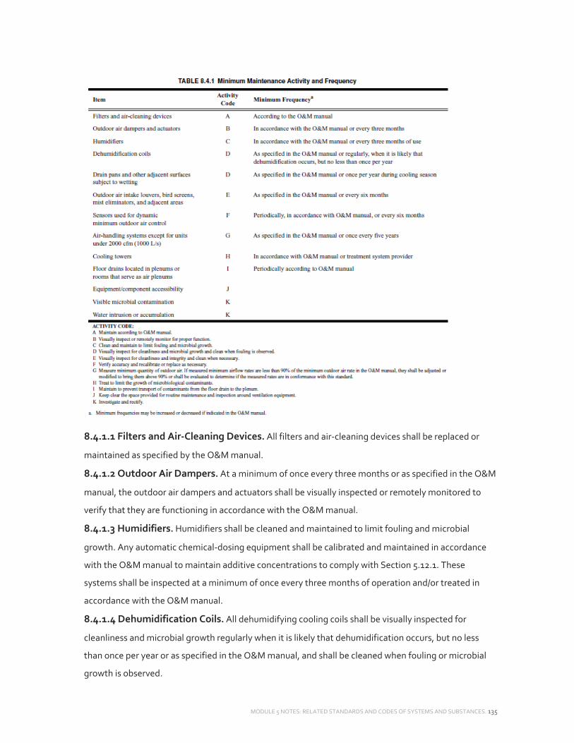
MODULE 5 NOTES: RELATED STANDARDS AND CODES OF SYSTEMS AND SUBSTANCES. 135
8.4.1.1 Filters and Air‐Cleaning Devices. All filters and air‐cleaning devices shall be replaced or
maintained as specified by the O&M manual.
8.4.1.2 Outdoor Air Dampers. At a minimum of once every three months or as specified in the O&M
manual, the outdoor air dampers and actuators shall be visually inspected or remotely monitored to
verify that they are functioning in accordance with the O&M manual.
8.4.1.3 Humidifiers. Humidifiers shall be cleaned and maintained to limit fouling and microbial
growth. Any automatic chemical‐dosing equipment shall be calibrated and maintained in accordance
with the O&M manual to maintain additive concentrations to comply with Section 5.12.1. These
systems shall be inspected at a minimum of once every three months of operation and/or treated in
accordance with the O&M manual.
8.4.1.4 Dehumidification Coils. All dehumidifying cooling coils shall be visually inspected for
cleanliness and microbial growth regularly when it is likely that dehumidification occurs, but no less
than once per year or as specified in the O&M manual, and shall be cleaned when fouling or microbial
growth is observed.
MODULE 5 NOTES: RELATED STANDARDS AND CODES OF SYSTEMS AND SUBSTANCES. 136
8.4.1.5 Drain Pans. Drain pans shall be visually inspected for cleanliness and microbial growth at a
minimum of once per year during the cooling season, or as specified in the O&M manual, and shall be
cleaned if needed. Areas adjacent to drain pans that were subjected to wetting shall be investigated,
cleaned if necessary, and the cause of unintended wetting rectified.
8.4.1.6 Outdoor Air Intake Louvers. Outdoor air intake louvers, bird screens, mist eliminators, and
adjacent areas shall be visually inspected for cleanliness and integrity at a minimum of once every six
months, or as specified in the O&M manual, and cleaned as needed. When visible debris or visible
biological material is observed, it shall be removed. Physical damage to louvers, screens, or mist
eliminators shall be repaired if such damage impairs their function in preventing contaminant entry.
8.4.1.7 Sensors. Sensors whose primary function is dynamic minimum outdoor air control, such as
flow stations at an air handler and those used for demand control ventilation, shall have their accuracy
verified as specified in the O&M manual. This activity shall occur at a minimum of once every six
months or periodically in accordance with the O&M manual. A sensor failing to meet the accuracy
specified in the
O&M manual shall be recalibrated or replaced.
8.4.1.8 Outdoor Airflow Verification. The total quantity of outdoor air to air handlers, except for
units under 2000 cfm (1000 L/s) of supply air, shall be measured in minimum outdoor air mode once
every five years. If measured minimum airflow rates are less than the design minimum rate (±10%
balancing tolerance) documented in the O&M manual, they shall be adjusted or modified to bring them
to the minimum design rate or evaluated to determine if the measured rates are in compliance with this
standard.
8.4.1.9 Cooling Towers. Cooling tower water systems shall be treated to limit the growth of
microbiological contaminants including legionella sp. in accordance with the O&M manual or the water
treatment program.
8.4.1.10 Equipment/Component Accessibility. The space provided for routine maintenance and
inspection around ventilation equipment shall be kept clear.
8.4.1.11 Floor Drains. Floor drains located in air plenums or rooms that serve as plenums shall be
maintained to prevent transport of contaminants from the floor drain to the plenum.
8.4.2 Microbial Contamination. Visible microbial contamination shall be investigated and rectified.
8.4.3 Water Intrusion. Water intrusion or accumulation in ventilation system components such as
ducts, plenums, and air handlers shall be investigated and rectified.