SPECIAL SPECIFICATION 5448 Natural Gas...
50
1-15 5448 02-07 2004 Specifications CSJ 0072-08-119 (This specification has 2 exhibits, GAS-3 and GAS-4) SPECIAL SPECIFICATION 5448 Natural Gas Pipeline 1. Description. Obtain all natural gas pipeline materials from a designated CPS Energy (CPS ENERGY) Center (a municipal agency of the City of San Antonio), transporting and unloading the CPS ENERGY furnished materials at the project site; and for furnishing all other materials, tools, supplies, labor and equipment necessary for a complete natural gas pipeline in conformance with the details shown on the plans, this Item and as directed by the Engineer. The term “Engineer” is defined as “the TxDOT and/or the CPS ENERGY Engineers and their representatives”. Be responsible for the construction of complete facilities, conforming in all respects with the details shown on the plans and as covered by this Item including the design standards, Exhibit GAS-3 and/or Exhibit GAS-4 that are a part of and located at the end of this Item. No gas service may be cut/turned-off after 2:30 PM each day. All gas services cut/turned- off during the day shall be restored before 4:00 PM that same day. All work shall be coordinated with the Engineer. All natural gas pipeline work shall conform with Title 49 of the Code of Federal Regulations (CFR), Part 192, “Transportation of Natural and Other Gas by Pipeline: Minimum Federal Safety Standards”, and to the design standards and details shown on the plans and/or included in this Item. Perform the natural gas pipeline work required to abide by the regulations of 49 CFR Part 40, “Procedures for Transportation Workplace Drug Testing Programs”, and 49 CFR Part 199, “Control of Drug Use in Natural Gas, Liquefied Natural Gas, and Hazardous Liquid Pipeline Operations”, to test employees for the presence of prohibited drugs as prescribed and to provide an employee assistance program. Provide the Engineer with an affidavit prior to beginning the work which states that they have complied with all applicable laws, statutes and regulations pertaining to ensuring a drug and alcohol free workplace including but not limited to the requirements of 49 CFR as amended by RSPA. Submit a copy of their anti-drug and alcohol plan for drug and alcohol testing prior to beginning the work and allow the Engineer's representative, periodic on-site access to records documenting compliance with these regulations Indemnify the State and CPS ENERGY against any fines, penalties, damages, costs or attorney fees based on violation of this requirement. Provide the Engineer, the name and contact person for the agency or consortium used to ensure compliance with this requirement. The Contractor that is going to perform the natural gas pipeline work is required to have performed other utility gas pipeline work within the previous 3 years of similar technical
Transcript of SPECIAL SPECIFICATION 5448 Natural Gas...

1-15 5448 02-07
2004 Specifications CSJ 0072-08-119 (This specification has 2 exhibits, GAS-3 and GAS-4)
SPECIAL SPECIFICATION 5448
Natural Gas Pipeline
1. Description. Obtain all natural gas pipeline materials from a designated CPS Energy (CPS ENERGY) Center (a municipal agency of the City of San Antonio), transporting and unloading the CPS ENERGY furnished materials at the project site; and for furnishing all other materials, tools, supplies, labor and equipment necessary for a complete natural gas pipeline in conformance with the details shown on the plans, this Item and as directed by the Engineer. The term “Engineer” is defined as “the TxDOT and/or the CPS ENERGY Engineers and their representatives”.
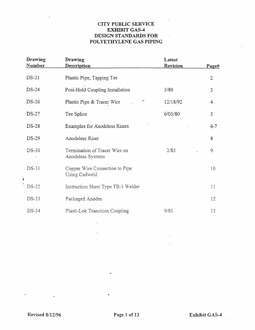
Be responsible for the construction of complete facilities, conforming in all respects with the details shown on the plans and as covered by this Item including the design standards, Exhibit GAS-3 and/or Exhibit GAS-4 that are a part of and located at the end of this Item.
No gas service may be cut/turned-off after 2:30 PM each day. All gas services cut/turned-off during the day shall be restored before 4:00 PM that same day. All work shall be coordinated with the Engineer.
All natural gas pipeline work shall conform with Title 49 of the Code of Federal Regulations (CFR), Part 192, “Transportation of Natural and Other Gas by Pipeline: Minimum Federal Safety Standards”, and to the design standards and details shown on the plans and/or included in this Item.
Perform the natural gas pipeline work required to abide by the regulations of 49 CFR Part 40, “Procedures for Transportation Workplace Drug Testing Programs”, and 49 CFR Part 199, “Control of Drug Use in Natural Gas, Liquefied Natural Gas, and Hazardous Liquid Pipeline Operations”, to test employees for the presence of prohibited drugs as prescribed and to provide an employee assistance program. Provide the Engineer with an affidavit prior to beginning the work which states that they have complied with all applicable laws, statutes and regulations pertaining to ensuring a drug and alcohol free workplace including but not limited to the requirements of 49 CFR as amended by RSPA. Submit a copy of their anti-drug and alcohol plan for drug and alcohol testing prior to beginning the work and allow the Engineer's representative, periodic on-site access to records documenting compliance with these regulations Indemnify the State and CPS ENERGY against any fines, penalties, damages, costs or attorney fees based on violation of this requirement.
Provide the Engineer, the name and contact person for the agency or consortium used to ensure compliance with this requirement.
The Contractor that is going to perform the natural gas pipeline work is required to have performed other utility gas pipeline work within the previous 3 years of similar technical

2-15 5448 02-07
scope and magnitude as the work to be performed for this project. Provide evidence of this previous experience requirement or obtain approval through other means deemed acceptable as determined by the Engineer. Contact CPS ENERGY prior to letting to determine if previous experience meets this requirement.
Locate all existing gas facilities as needed for the construction and installation of new gas facilities. Upon request, the Engineer will provide copies of the appropriate CPS ENERGY gas maps to facilitate locating activities for the existing facilities at the project site; however, the Engineer and CPS ENERGY do not guarantee the accuracy of such gas facilities map information. Use conventional pipe locating equipment and techniques in conjunction with information from the maps to determine the actual location of existing gas facilities and be liable for any damages to existing gas facilities and any other utilities that are incurred by construction activities.
While this Item and the details shown on the plans are intended to be full and complete, the Contractor is considered bound by customary good construction practice whether referred to specifically or not.
2. Materials. CPS Energy will provide all natural gas pipe (steel and/or plastic), couplings, valves, valve boxes, stop cocks, anodeless risers, miscellaneous fittings, pipe tracer wire, and any other natural gas pipeline materials necessary to complete the work. These materials will be provided by CPS ENERGY at no cost to the Contractor. Notify the Engineer 10 days prior to scheduling the pick-up of these materials. All other materials, tools, supplies, equipment, etc., necessary to complete the work shall be furnished by the Contractor.
When the materials stored at the CPS ENERGY Centers are issued, they become the Contractor's responsibility. A transfer-of-inventory will be signed as a written record of the materials provided. The Contractor, the State and CPS ENERGY will jointly inspect and inventory the materials for quantity and quality at the time of loading at the CPS ENERGY Center and will sign the inventory list. After this transfer, the Contractor will be responsible for CPS ENERGY's delivered costs for any materials that have to be replaced due to lost or damaged beyond use during the project. “Damaged Beyond Use” will be determined by the Engineer.
Load the materials at one or more CPS ENERGY Center(s) in San Antonio, transport and unload at the work area. All materials are to be unloaded (not dropped) with proper equipment to prevent damage.
Deliver the materials along the right of way in such a manner as to not cause interference to driveways, streets, other construction operations, sidewalks, etc. Prevent dirt or debris from entering into the pipe, couplings, fittings, etc.
Upon completion of the gas work, promptly return excess materials furnished by CPS ENERGY to the designated CPS ENERGY Center(s).
3. Construction Methods.
Excavation. Excavation (trenching) required to complete the pipeline installation will have sufficient width to allow installation of piping and valves at depths specified on the plans
3-15 5448 02-07
and/or the design standards shown at the end of this Item. Blasting to perform the excavation is not allowed. In cases where shrubbery and trees that are labeled to remain are encountered in any location where in the opinion of the Engineer the use itching/trenching equipment may result in unnecessary damage, the Engineer may require the trench to be excavated by hand.
Dust Suppression. Whenever trenching activities create significant amounts of dust or other undesirable emissions into the atmosphere, take action to reduce these emissions, as determined by the engineer.
Boring. At the locations shown on the plans, the pipe installation is accomplished with a boring operation using the following methods.
The use of guided or directional boring equipment is acceptable if the Contractor demonstrates such equipment is capable of installing the pipe along a controlled and relatively constant horizontal and vertical alignment. Insure that the pipe is not damaged as it is pulled or otherwise inserted into the bored hole. The bored hole must be at least 1 nominal pipe size larger than the pipe to be installed (i.e. a 4 in. pipe requires at least a 6 in. bored hole). When the bored hole is known to have significant deflections, the bored hole must then be at least 2 nominal pipe sizes larger than the gas pipe.
When boring equipment is used to install plastic pipe, a fusible link will be used between the pull head and the pipe at all times to prevent damage during the pull-back operation. The fusible link shall be at least 2 ft. in length and be a section of pipe that is 1 nominal pipe size smaller that the pipe being installed.
The Engineer will inspect the fusible link and the leading edge of the installed pipe for any significant gouges or scrapes in the outside wall of the pipe or excessive change in length of the fusible link. If damages to the fusible link or pipe are found, remove and replace all of the damaged pipe, and reimburse CPS ENERGY for the cost of the damaged pipe (including CPS ENERGY inventory and handling expenses).
When boring equipment is used to install steel pipe, the Engineer is to inspect the installed pipe for any significant gouges or scrapes in the protective coating on the outside wall of the pipe. If damages to the coating are found, repair all of the damaged coating at no additional cost.
Whenever service lines are planned for installation along a section of gas main that is being installed with guided or directional boring equipment, excavate at least 1 service tap location to provide an intermediate inspection hole prior to pulling the pipe into the bored hole. The intermediate inspection hole is to be located near the middle of the directional bored section. If several service line connections are planned along the route, the Engineer must approve the location of the service tap that is excavated for the intermediate inspection hole before the pipe insertion process.
Mains and service lines that are installed by guided or directional boring equipment must not be installed at depths greater than 7 ft. unless one of the following conditions applies:
The plans specifically require installation depths in excess of 7 ft.
4-15 5448 02-07
Installation depths in excess of 7 ft. are necessary to achieve acceptable clearance between the pipe and another utility or structure while maintaining the minimum burial depth requirements for the pipe.
The Engineer's prior approval for such installation when the conditions described above are not applicable.
When guided or directional boring equipment is used to install gas distribution facilities, additional compensation due to extra depth of cover will not apply.
The method of gas service replacement by insertion involves sliding a new polyethylene pipe of smaller diameter into the existing pipe. This is an acceptable method of installation provided the ends of the existing steel pipe are reamed and fitted with bushings for the pipe to be inserted without damage, and a shrink sleeve is applied to keep components in place and prevent damage thereafter. In order to reduce stress on the service line being inserted from the main, the horizontal distance between the end point of the new service alignment and the point of insertion should be at least, twice the perpendicular distance between the lines (see the Insertion Detail, exhibit GAS-3). Tracer wires will be inserted through the existing service along with the new pipe. An electrical continuity test will be conducted on each installed tracer wire to verify that the wire has not been “shorted” against the existing steel service during the installation procedure.
Temporary Bridges. When the trench is excavated where it is necessary to have a passageway across an open trench, provide safe, temporary bridges or provide other safe means of crossing the trench as approved by the Engineer.
No streets, alleys or driveways are to be blocked at night, except with the Engineer's prior approval. Trenches/holes left open during non-working periods (overnight, a weekend, etc.) shall be properly protected and with barricades and warning lights.
Protection of Pipe Ends. Keep the pipeline installation clean. At the end of each day's work and at any other times that the ends of the installed pipe are left unattended, the pipe ends must be securely closed to prevent the entrance of water, animals, trash or any other obstructions, and not opened until work is resumed.
If there is reasonable cause to believe that there is an obstruction in a portion of the lines, remove all foreign matter if it is in the lines. The work necessary to assure that foreign matter is not present and/or to remove the foreign matter if it is present is at the Contractor's expense.
Welding. All welding is in accordance with API Standard 1104, 18th Edition, dated September, 1994 (or the latest edition), as outlined herein, as shown on the plans, and/or as directed/approved by the Engineer.
Welds are to be made with the “shielded metal-arc” process. All welding equipment and materials such as welding rods will be furnished by the Contractor. Brand of welding rods proposed must be approved by the Engineer prior to use.
Where determined by the Engineer to be necessary, back-welding or inside-welding of all tube turns, ells, etc., in the pipeline is to be performed as part of the required work.

5-15 5448 02-07
All welds to be made with not less than 3 beads. The second or “Hot Pass Bead”, should be run on the full circumference of the pipe as soon as practical where the Hot Pass or second bead is run before the Stringer Bead has cooled.
Prior to being allowed to weld, each welder must qualify in accordance with Section 3.0 of API Standard 1104 and must pass the tests listed in paragraph 3.4 of this Standard. Conduct, or make arrangements for, qualification tests for welders. The qualifying tests will be conducted in the presence of the Engineer.
Each welder will be assigned a specific number and it will be the welder's responsibility to affix his/her number with a crayon next to each weld for future identification. Steel die stamping is not be used.
Welding inspection, is in accordance with Section 5.1 of API Standard 1104. Test all welds with soap suds while the line is subjected to an internal air pressure of 90 PSI prior to field coating the joints.
Pin holes, leaks, cold laps, rivers, undercutting or any other defects occurring in any weld, are to be repaired by cutting out the entire weld and completely rewelding. Whenever it becomes necessary to remove a weld from the completed line, replacement is made by welding into the line a pup joint having a minimum length of 10 ft.
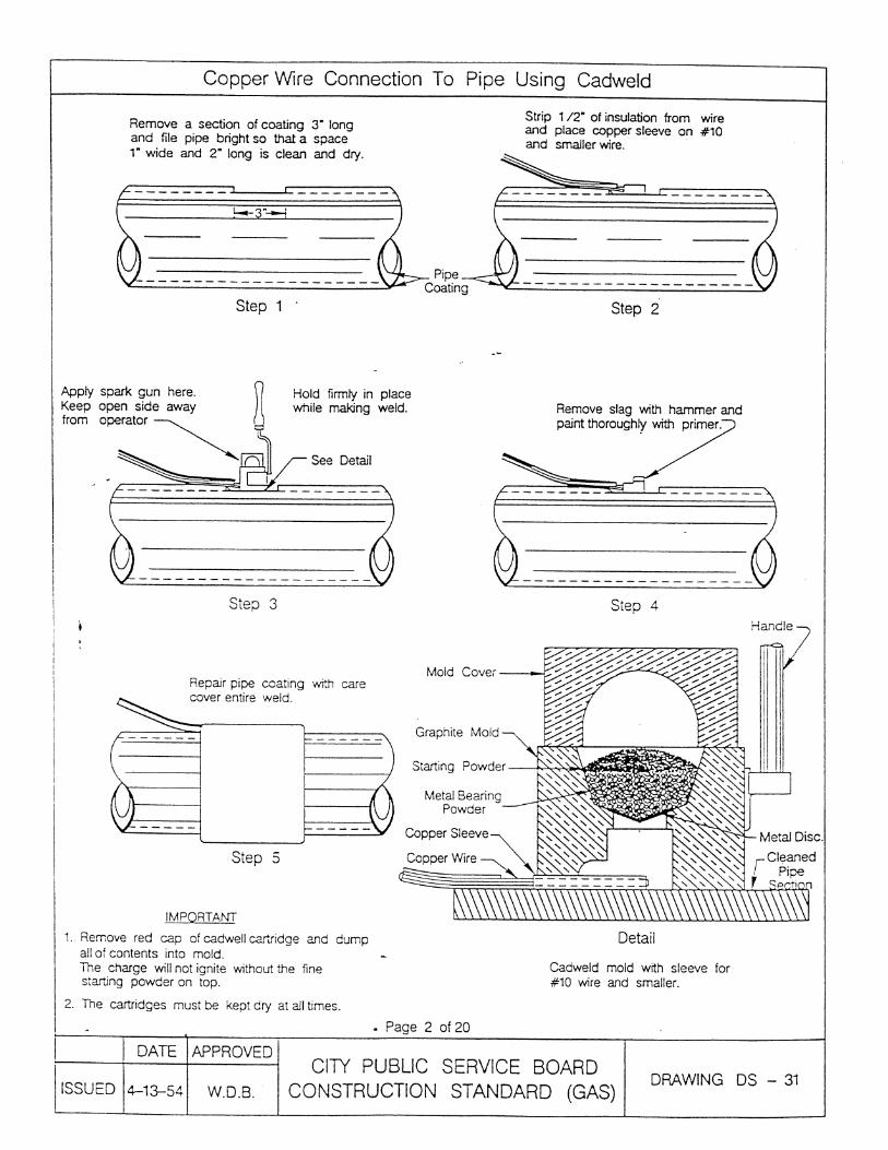
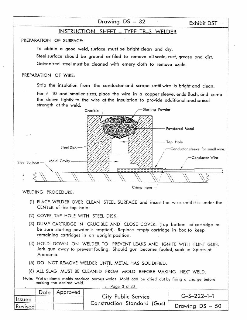
Coating of Pipe. Coating materials for coating field joints and for repairing damaged or defective coating will be furnished by CPS ENERGY.
If the pipe furnished by CPS ENERGY is coated and wrapped pipe, the Contractor will be responsible for coating all field joints and repairing damaged and defective coating on the pipe regardless of the nature, extent or cause of damage or defect. However, if the pipe provided had a damaged or defective coating of such magnitude as to require an extra charge to properly coat, first refer this matter to the Engineer and not proceed until authorization to do so has been obtained, in which event the provisions of Item 9, “Measurement and Payment”, will be used to pay for this work.
For coating field joints of pipes coated with TGF-3 coal tar enamel, the coating on the pipe must be cut back a distance of 8 to 12 in. from the joint. The edge of the enamel and felt wrapping is to be feathered at these points to assure a firm bond between the original coating and the field coating. After the joints are welded and tested, and the welds cleaned and brushed, the bare ends of the pipe are to be thoroughly cleaned, then immediately given a hand-brushed coat of primer to dry surfaces. Exercise care to prevent primer from being applied too heavily, especially at the base of the welds; any runs or sags which have dried or dead primer must be scraped off and the pipe reprimed. After the tape primer has dried to a tacky consistency, apply cold wrap tape with a 30% overlap, taking care not to create any voids between the pipe and tape coating. No primer or coating will be applied to wet or damp pipe.
All repairs to damaged coating which exceeds 2 sq. in. will be made by breaking out the old coating, scraping the pipe to bare metal, feathering the edges to assure a firm bond and repriming. After the primer has dried to a tacky consistency, apply cold wrap tape taking care not to create any voids between the pipe and the tape coating. For repairs less than 2 sq. in., the pipe does not have to be scraped to bare metal and primed;
6-15 5448 02-07
however, the good enamel around the damaged portion is to be feathered before the cold wrap is applied.
Repairs to Fusion Bonded Epoxy and/or Powercrete coated pipe may include the following additional repair procedures.
For pinhole and small area repair, the pipe surface and small area holidays where repairs by the patching stick method are approved by the Engineer and is a recommended procedure by the coating manufacturer, the original coated surface must be thoroughly cleaned and lightly abraded with sandpaper. Patching stick material is to be compatible with the F.B.E. epoxy coating system and is to be material normally supplied by the manufacturer of the F.B.E. coating system. It is to be applied by heating the clean pipe surface until the patching stick begins to melt when it is rubbed over the heated area. Continue heating the coated surface while applying the patching stick like a brazing rod. Build a small puddle of melted compound to obtain a minimum thickness of 0.025 in. Continue heating until the compound flows out smoothly. In all instances the manufacturer's recommendations for the use of the patching stick are to be followed.
An alternate method, for repairs to small area holidays, is liquid epoxy. The material for patching is to be 100% solids catalytically cured epoxy coating normally supplied by the manufacturer of the F.B.E. coating system. The original coated surface must be thoroughly cleaned and lightly abraded with sandpaper. All dust is to be wiped off before applying the patch coating. This type of repair coating is to be applied by spatula, brush, roller or spray to attain a uniform minimum thickness of 0.025 in. and is to overlap the surrounding undamaged coating by at least 1 in. The patch coating is not to be applied when pipe temperatures are below 50ºF unless provisions are made for complete heat curing, using methods and temperatures in accordance with procedures recommended by the patch coating manufacturer.
At the option of the Engineer, completely cured coating repairs are to be inspected with the Contractor's holiday detector. A patch-coated area is to be allowed to cure prior to handling as per manufacturer's specifications. Supply necessary equipment to complete repairs to manufacturer's guidelines.
For large area repair, where repairs are approved by the Engineer, the following procedures are to be followed. The pipe is to be cleaned to remove all dirt, scale, rust, damaged of disbonded coating and other foreign material. Areas repaired before surface oxidation or rusting occurs may be prepared by hand sanding, power tool grinding, or surface oxidation or other approved and suitable means. Areas repaired after surface oxidation or rusting occurs are to be cleaned using abrasive blasting prior to coating repairs. The edges of the original coating are to be “feathered out” around the area to be coated and all dust wiped off before applying the patch coating.
The material for patch coating must be 100% catalytically cured epoxy coating supplied by the manufacturer of the F.B.E. coating system. This type of repair coating is to be applied by spatula, brush, roller or spray to attain a uniform minimum thickness of 0.025 in. or as recommended by the manufacturer. The patch compound is to overlap the surrounding undamaged coating by at least 1 in. A patch-coated area is to be allowed to cure prior to handling as per manufacturer's specifications. At the option of the Engineer, completely
7-15 5448 02-07
cured coating repairs are to be inspected with the Contractor's holiday detector. Supply necessary equipment to complete repairs to manufacturer's guidelines.
For coating field joints on fusion bonded epoxy coated pipe, heat shrink sleeves may be employed when approved by the Engineer. Heat shrink sleeves are to be the heat shrinkable wraparound sleeves with either a specially formulated mastic sealant or a solvent free, 2 component liquid epoxy primer designed to prevent corrosion of joints on buried pipelines. Apply sleeves in compliance with manufacturer's recommendations. In addition, for field joints within bores, heat shrink sleeves may also be employed when approved by the Engineer, provided the sleeves are manufactured for this application. Sleeves for this application are to consist of a combination of the following components: A specially designed wraparound heat shrinkable sleeve, a high shear strength thermoplastic hot melt adhesive, a solvent free, 2 component epoxy, a specially designed wear cone, and optional clamping belts. Supply necessary equipment to install sleeves in accordance to manufacturer's recommendations. This may include, but not be limited to, high intensity gas torches and abrasive blast equipment for pipe surface preparation.
After the field joints have been coated and immediately before the pipe is lowered into the ditch, the entire coating will be tested to locate breaks or pinholes and other flaws in the coating with an approved holiday detector in good working condition capable of producing the testing voltage in pulsating cycles at very low amperage. The voltage used is not to exceed 14,000 volts for pipe coatings of 0.094 in. For fusion bonded epoxy coated pipe, the coating is to be checked for holidays using a dry-type holiday detector. The holiday detector is to be set at 150 volts per mil thickness of coating. All defective places will be plainly marked immediately. Furnish the holiday detector, and check the coating for holidays in the presence of the Engineer.
Compression type couplings, valves, welded fittings, etc., will receive a cold applied mastic after the pipe is in the trench and has been tested for leaks. A plastic wrap supplied by CPS ENERGY will be installed over the mastic to protect the coating during backfilling.
Handling coated pipe is to be accomplished only with suitable equipment to prevent damage to the coating. The coated pipe is to be placed on skids alongside the trench until it is to be welded and lowered into the trench. The skids are to be of sufficient width or padded with sand bags or resilient pads to prevent the skid edges from cutting the coating and wrapping. The skids are to be arranged to permit the coated pipe to bear on the full width of the skid.
Coated and wrapped pipe is to be carefully handled with wide rubber, leather, composition, or canvas slings or belts containing no protruding rivets or belts that may damage the coating. Wire rope, tongs, chains, hooks, and bare cables must not come into contact with the coating. Coated pipe is not to be handled when the temperature is low enough to cause cracking of the enamel.
Plastic Gas Pipe. Handle the pipe only with suitable equipment to prevent damage to the pipe such as fracture, kinking, deep gouges or cuts. The pipe is not to be subjected to abuse by dropping, throwing or dragging except over smooth non-scratching terrain or surface.

8-15 5448 02-07
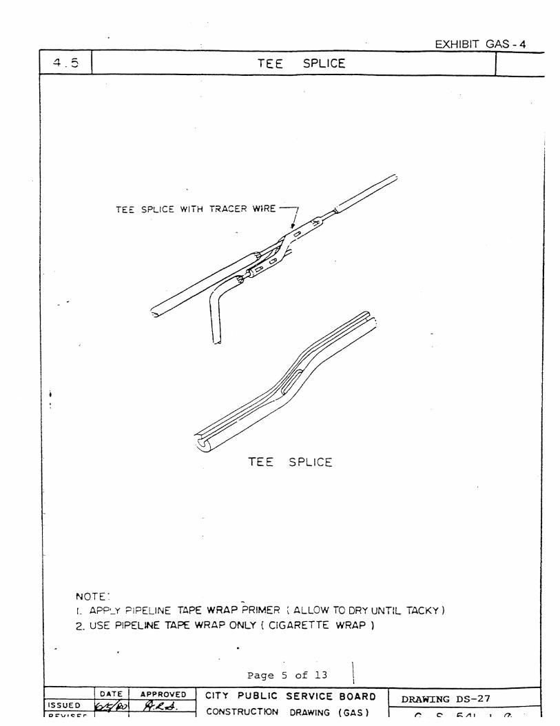
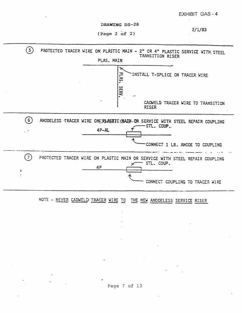
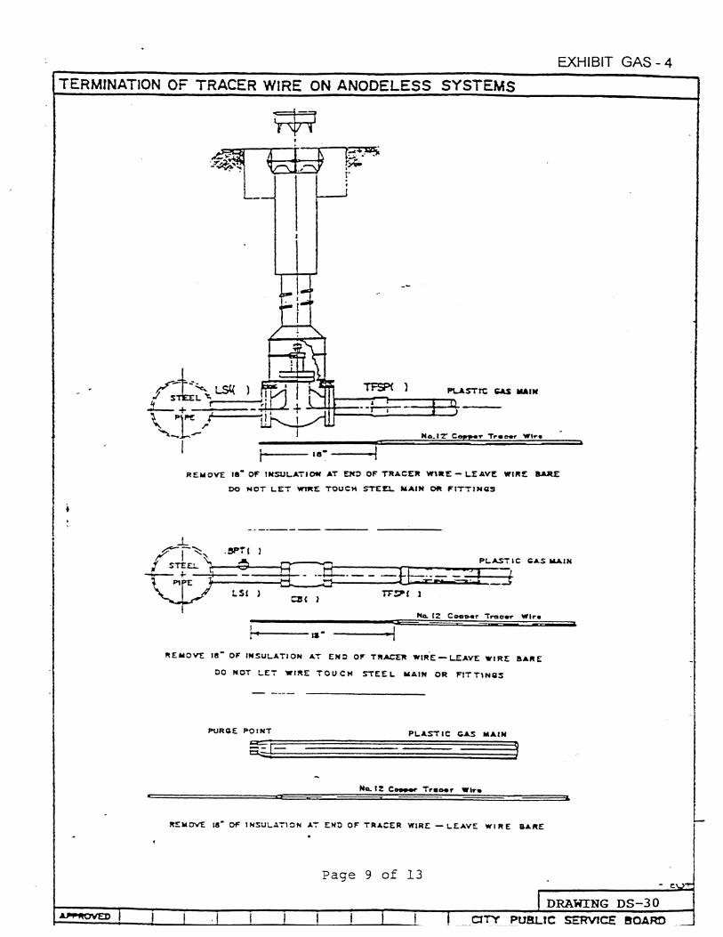
Install an insulated copper tracer wire furnished by CPS ENERGY with all pipe for the purpose of locating the pipe after backfilling. This wire is to be installed with 2 to 6 in. of separation from the pipe.
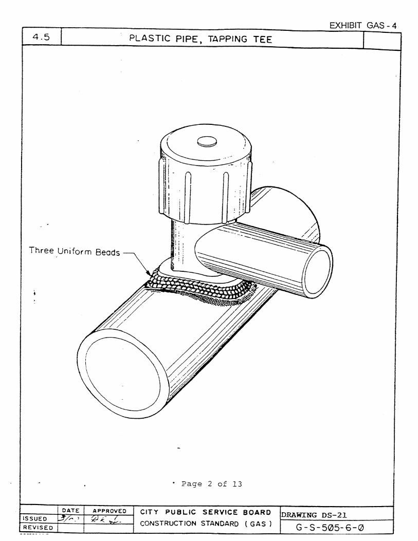
Fuse pipe joints in accordance with requirements of 49 CFR Part 192, “Transportation of Natural and Other Gas by Pipeline: Minimum Federal Safety Standards”, Paragraphs of 192.281, 192.283, 192.285, 192.287.
Prior to starting production fusing, each employee that will be making fusion joints must qualify according to 49 CFR Part 192, Paragraph 285. Conduct, or make arrangements for the qualification tests. The qualifying tests are to be conducted in the presence of the Engineer.
Furnish all specialty tools and equipment required to handle, install, butt fuse and squeeze-off the pipe. Insure all specialty tools and equipment are specifically designed for use on plastic piping systems and are in good working condition. The Engineer may inspect all specialty tools and equipment and may disallow the use of any specialty tools or equipment that are not specifically designed for use on high density polyethylene (plastic) piping systems or are deemed to not be in good working condition. CPS ENERGY routinely uses the Steve Vick & Mark II Coil Trailor for handling large diameter coiled pipe, McElroy equipment for making butt fusions on plastic pipe and Mustang Squeeze-off tools for stopping the flow of gas in existing plastic piping systems. Provide copies of the manufacturer's literature for all comparable equipment from other manufacturers and at the discretion of the Engineer, comparable equipment from other manufacturers may be approved.
All pipe joints are to be soap bubble tested with the line having between 90 and 120 PSIG internal pressure. The test is to be made in the presence of the Engineer.
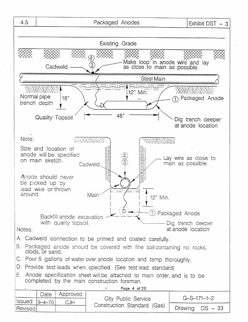
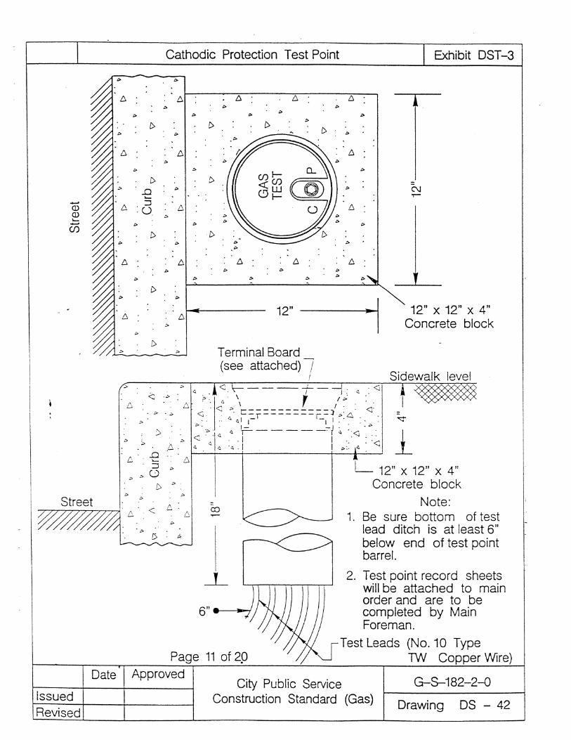
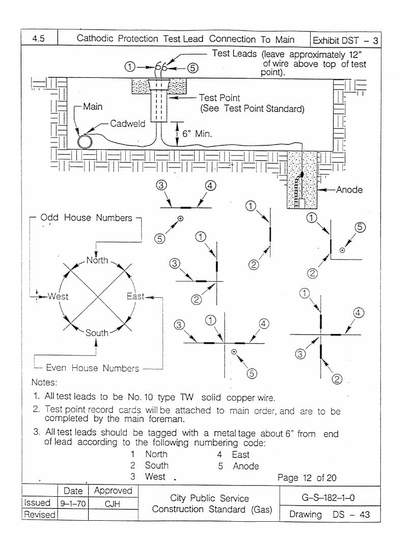
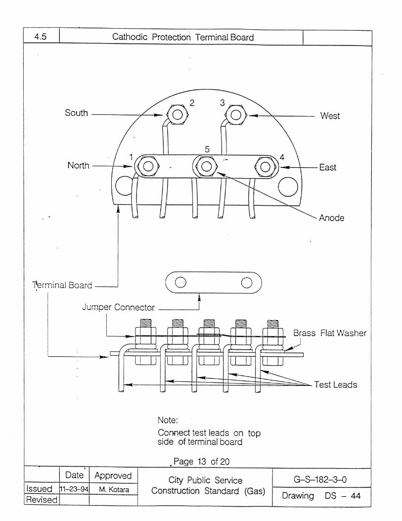
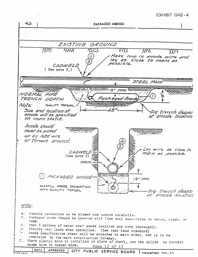
Cathodic Protection. Install packaged anodes, insulating joints and insulating flange sets as provided for by this Item and/or as shown on the plans. Welding machines are not be used to test insulation or otherwise be grounded across insulating devices. Insulation will be checked by the Engineer and declared acceptable only after testing establishes satisfactory performance.
Installation and Backfill. All stumps and roots found in the trench are to be cut and removed where they will not come in contact with the pipe. All loose rocks, stones, blocks, heavy clods, tree limbs, etc., which may damage or prevent proper installation of the pipe are to be removed before the pipe is installed. The pipe will not be lowered into the trench until it has been inspected and approved by the Engineer.
The trench is to be excavated a minimum of 4 in. deeper than the proposed pipe depth so that a commercial sand approved by the Engineer can be placed in the trench before the pipe is installed. The sand placed in the trench to cushion the pipe is to be leveled and tamped so that the weight of the pipe is evenly distributed on the sand cushion.
Unless the plans or the Engineer requires flowable backfill, backfilling must be conducted in a manner where the trench will be neatly and uniformly backfilled and compacted. Exercise care to prevent hand shovels and tampers from damaging the pipe. Provide 6 in. of sand backfill around and over the pipe to form a protective cushion between the pipe and the
9-15 5448 02-07
materials and equipment used for backfilling. After the pipe has a 6 in. minimum cover of sand, the remaining backfill may contain rocks and gravel, except that large rocks in excess of 4 in. in diameter, width or length, shall not be used.
When crossing drainage ditches and minor streams, furnish and install all materials necessary for bank reinforcement. The backfill is to be properly maintained until the work has been completed and accepted. No reimbursement will be made for repairing of backfill due to floods and/or other conditions occurring before final acceptance.
Control the excavation and backfilling operation to have a minimum amount of open trench commensurate with good construction practices. Any surplus material not used for backfilling is to be disposed of properly. Attain the minimum specified cover for the gas piping.
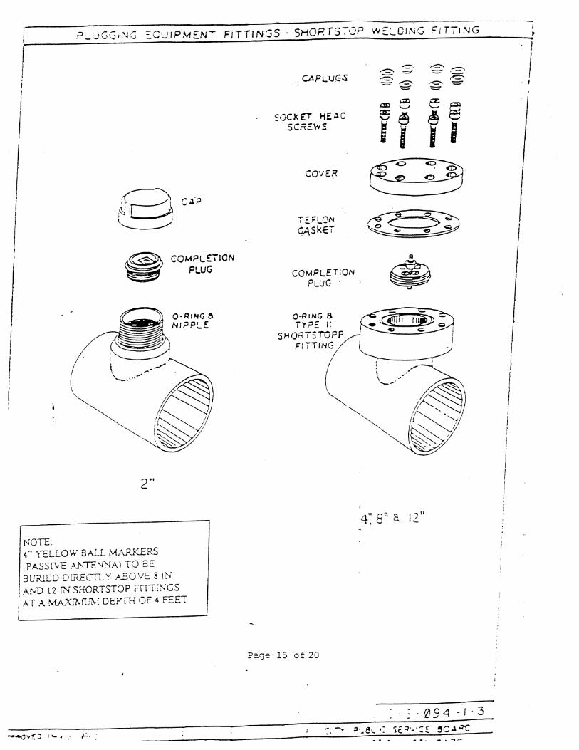
Final Piping Connections, Tie-Ins and Purging. Make all connections of new gas lines to existing gas lines. This includes all necessary preparations for tie-ins and purging for all sections of gas lines installed. Weld short stop fittings and other necessary fittings on existing steel gas lines that will be used by CPS ENERGY to control the flow of gas into the new gas lines. CPS ENERGY will control the flow of gas on all operative gas facilities while the Contractor is making final piping connections and/or tie-ins.
CPS ENERGY will purge the new gas mains, and the Contractor will purge all new and/or existing service lines that have been tied to the new gas mains or otherwise adjusted.
Furnish all necessary equipment and instrumentation that is required to insure that the final tie-in welds and/or fusions between new and existing gas facilities are performed in a safe manner. Such equipment and instrumentation may include pneumatic air movers, combustible gas indicators (CGI's), oxygen monitors, self-contained breathing apparatus and fire retardant clothing for construction personnel, and fire extinguishers.
Clean-Up. As soon as backfill is completed on a section of pipeline, clean the right of way, remove and transport all surplus CPS ENERGY issued materials to the designated CPS ENERGY Center(s). Dispose of all refuse such as brush, broken skids, rock, etc. The earth on both sides of the trench which has been disturbed during the construction of the gas line is to be leveled, and the entire area left in a condition satisfactory to the Engineer.
4. Tests.
Radiographic Inspection. Applies when radiographic inspection is specified by this Item or by the plans.
Standards and Codes. The latest edition of the following documents apply when required:
(i) Department of Transportation, 49 CFR Part 192, “Transportation of Natural and Other Gas by Pipeline: Minimum Federal Safety Standards”.
(ii) Recommended Practice No. SNT-TC-1A, Supplement A “Radiographic Testing Method”.
(iii) ANSI B31. 8, “Gas Transmission and Distribution Piping Systems”.

10-15 5448 02-07
(iv) ASME Code Section V, “Nondestructive Examination”.
(v) United States Nuclear Regulatory Commission, Title 10, Chapter 1, CFR - Energy and other federal, state and local regulations for protection against radiation hazards.
Radiographic Procedure. Perform all radiographic inspections in accordance with Section 8.2 of API Standard 1104. The Contractor is to provide a copy of the written procedure to the Engineer for acceptance.
Personnel Qualifications. Radiographic certification will be through a qualification and certification program that incorporates the requirements of Recommended Practice No. SNT-TC-1A, Supplement A in accordance with Section 8.7 of API Standard 1104.
Equipment and Material. Furnish all equipment and materials necessary for the performance of the radiographic inspection. The materials and equipment include all film and supplies for the processing, film identification, recording, filing and storage. Provide all barriers, warning systems, film badges, documentation and records necessary for the protection and personnel monitoring of every person near a radiation source.
Production Radiography Procedures. Notify the Engineer if any welds fail to meet the radiographic inspection. All welds or welded joints that are repaired or replaced are to be radiographed again.
Film Identification Procedure. Film identification is in accordance with Section 8. 6 of API Standard 1104. The method of identification will be as approved by the Engineer prior to the start of radiographic inspection.
Radiographic Reports and File. Furnish the Engineer a report for each calendar day the unit is on the project. All radiographs made are to be delivered to the Engineer and become the property of CPS ENERGY.
Pressure Testing. Demonstrate to the satisfaction of the Engineer, by performing a pressure test, that the mains and/or services installed do not leak and will operate safely at the desired maximum allowable operating pressure. Pressure tests will be performed to verify satisfactory workmanship and the strength of materials. To the extent practical, the test is to be conducted to the entire pipeline to minimize the number of untested tie-in connections. All joints used to tie-in a test segment of pipeline after the test are to be soap bubble tested at not less than its operating pressure. Repair any leaks or failures which are revealed by the test.
Furnish all supervision, labor, materials and equipment to perform the pressure test, including but not limited to, pumps, compressors, pigs, test instrumentation and water. Pressure test requirements will be as indicated on the plans. The requirements indicate the minimum and maximum test pressure, test fluid and test duration, as appropriate. Conduct the test in accordance with the applicable requirements of 49 CFR Part 192 and take all necessary safety precautions to protect construction personnel and the general public during the test. Obtain all permits necessary to conduct the test except for the Railroad

11-15 5448 02-07
Commission of Texas test water discharge permit that is required for a hydrostatic pressure test.
Standard Air Test. Gas mains and services to be operated at pressures of 60 PSIG or less. This test will be indicated in Exhibit SKT-2 without a test duration period. The test pressure is to be a minimum of 90 PSIG and a maximum of 120 PSIG. The test duration is to be sufficient to ensure discovery of all leaks. At the minimum, each weld, butt fusion and any other fitting and connection is to be soap bubble tested at the specified test pressure. The test pressure is to be measured with a dial type gauge and monitored during the course of the test to detect leakage. Upon completion of the test, furnish the Engineer with a written statement to indicate successful completion of the test. Pending acceptance of the test by the Engineer, the Engineer must also sign the statement.
High Pressure Test.
(i) When the plans specify a test pressure greater than 90 PSIG or if a specific test duration period is specified, the following applies.
Prior to initiating any work required for a High Pressure Test, hold a pre-test meeting with the Engineer to discuss all aspects of plans for conducting the High Pressure Test. The key points of discussion for hydrostatic pressure tests will include the following: 1) optimum direction and injection rate for filling the pipe section with water while minimizing air entrapment; 2) optimum direction and discharge location for safely and completely draining the pipe section; 3) the type, quantity and condition of pipeline pigs; 4) installation and use of temporary pig launchers and/or receivers; 5) capacities of water pumping equipment; 6) pressurization procedures; 7) written test documentation; 8) limitations on refilling and/or discharging test water during the pressure test without invalidating the test and causing the test to be restarted; 9) test water stabilization period after filling the pipe section; 10) appropriate procedures for dewatering the pipe section to minimize the amount of water that remains in the pipe; 11) any other aspects of High Pressure Test.
The test medium may be either air or water as shown on the plans. A hydrostatic test is to be conducted in general conformance with API Recommended Practice (RP) 1110. Conduct air tests in conformance with API RP 1110 with regard to safety and instrumentation.
(ii) All filling and pressurization procedures are subject to the approval of the Engineer. When a hydrostatic test is performed, fill the pipeline in a manner that no air is entrapped, making use of pipeline pigs as necessary. Furnish all pipeline pigging equipment, including appropriate styles and types of pipeline pigs and temporary pig traps and launchers. The Engineer will inspect all pigging equipment, and the equipment is to be acceptable to the Engineer prior to use. Allow a suitable time for temperature stabilization of the test fluid. The stabilization period is to be a minimum of 24 hours after the filling operation is complete for a hydrostatic test or, for an air test, 8 hours after the

12-15 5448 02-07
pipeline is pressurized to the minimum test pressure. The stabilization period may be reduced by the Engineer for short sections such as offsets, etc.
(iii) Note each significant step or event during the filling, pressurization and testing operation and comments are to be added for any incidents which may affect the results of the test. Where the specified test duration is 2 hours or less deadweight pressure, pipe temperature and ambient temperature measurements are to be recorded at 15 min. intervals. For tests whose duration is greater than 2 hours, these measurements are to be recorded at 30 min. intervals.
(iv) Upon completion of the test, obtain the approval of the Engineer prior to depressurizing the pipeline. Depressurize, de-water, clean and dry the pipeline to the satisfaction of the Engineer. Dispose of water in the manner required by (if any) permits.
Test Records. Submit to the Engineer all documentation associated with all the tests, including a completed Form I, “Hydrostatic Test Record and Certification” of Appendix I, API RP 1110, (or substantially similar documentation), testing logs and all recorder charts. All documentation is to be labeled to identify the pipeline section that was tested, signed, and dated by the Contractor. Provide written confirmation to indicate successful completion of the test for the Engineer's approval.
Pipeline Availability (Test Period). The gas main installation including the backfill will not receive final acceptance until all gas main construction has been completed and the main has been in satisfactory operation. This date will be established by the Engineer in writing. If it is determined by the Engineer that adjustments, repairs, replacements or other correction measures are needed, promptly perform the correction or replacement and retesting work necessary at contractor’s expense including all work damaged by the correction or replacement of the defective work. Upon completion of the gas work, all subsequent test periods will be at the discretion of TxDOT.
5. Measurement. Measurement of completed and accepted work as described herein is as follows:
New service stubs for 1 in. through 4 in. diameter pipes placed in an open trench will be measured as each location shown on the plans and as directed by the Engineer. A service stub connected to the gas main located along the same side of the street as the property being serviced is referred to as a short side service stub. A service stub connected to the gas main located along the opposite side of the street from the property being serviced is referred to as a long side service stub. The following conditions apply for service stubs:
Service stubs installed from an existing gas main to 1 ft. inside property line for short side or long side service. Service stubs installed from a new gas main to 1 ft. inside property line for short side or long side service.
Re-running and lowering service lines for 1 in. through 4 in. diameter pipes will be measured as each location shown on the plans and as directed by the Engineer. The conditions for service lines shown in Sections 5.(1)(a) and (b) will apply for re-running and lowering service lines.

13-15 5448 02-07
Extending, connecting and pump testing an existing service line for 1 in. through 4 in. diameter pipe to a new gas main will be measured as each location shown on the plans and as directed by the Engineer.
Shortening, connecting and pump testing an existing service line for 1 in. through 4 in. diameter pipe to a new gas main will be measured as each location shown on the plans and as directed by the Engineer.
When there is a need for a new welded steel service tee or a steel gate valve to be welded, the new welded steel service tee or the steel gate valve will be measured for the welding required to install each fitting for a 1-1/4 in. steel tee or a 2 in. or 4 in. steel gate valve. In most instances, the existing service tee and/or valve will be utilized when re-running a service line off an existing steel gas main.
Uncovering and capping service lines at the gas main will be measured as each location shown on the plans and as directed by the Engineer.
Installing a gas main of the size and type shown on the plans in an open trench will be measured by the foot along the top of the trench.
Installing a steel pipe casing for a service line or a gas main of the size shown on the plans in an open trench will be measured by the foot along the top of the trench. The size of the steel pipe casing will be larger than the size of the service line or gas main, such as, using 2 in. casing for a 3/4 in. pipe, 3 in. casing for 1 in. or 1-1/4 in. pipe, 4 in. casing for a 2 in. pipe, etc. This does not include the pipe installed in the casing.
Boring for a service line or a steel pipe casing of the size specified on the plans will be measured by the foot of pipe installed in the bore. The size of the steel pipe casing will be larger than the size of the service line or gas main to be installed.
Installing a service line or gas main of the type and size shown on the plans into a previously installed casing will be measured by the foot of pipe installed in the casing. The size of the pipe will be a 3/4 in. pipe into a 2 in. casing, a 1 in. or 1-1/4 in. pipe into a 3 in. casing, a 2 in. pipe into a 4 in. casing, a 4 in. pipe into a 6 in. casing, a 6 in. pipe into a 8 in. casing, a 8 in. pipe into a 12 in. casing, a 12 in. pipe into a 16 in. casing or a 16 in. pipe into a 20 in. casing.
Excavation and backfill (except flowable backfill) and the work for cutting and restoring pavement will be measured in accordance with Item 400, “Excavation and Backfill for Structures”. The sand used as part of the backfill will be considered subsidiary to this Item. All testing of the gas main installations will not be measured for payment but is to be considered subsidiary to the various natural gas pipeline pay items.
Mobilization (Equipment and Materials) will be measured in accordance with Item “NGP Mobilization”, for one time mobilization to and/or from the job site. Any additional mobilization requested by CPS Energy that requires an extra charge for mobilization, first refer this matter to the Engineer and do not proceed until authorization to do so has been obtained.
6. Payment. The work performed and materials furnished for the installation of the natural gas pipeline in accordance with this Item and measured as provided under “Measurement” will

14-15 5448 02-07
be paid for at the unit price bid for the Items of work hereinafter described. These prices will be full compensation for hauling all CPS ENERGY furnished materials, preparation, excavation and backfill, for shaping and fine-grading the trench, for placing and connecting pipes, for coating the steel pipe, for installing all necessary fittings, for building and painting risers, for meter set-ups, furnishing materials not provided by CPS ENERGY, for all testing, disposition of surplus material and for all manipulations, labor, tools, equipment and incidentals necessary to complete the work.
Payment for new service stubs for 1 in. through 4 in. diameter pipe placed in an open trench will be at the unit price bid for “Natural Gas Pipeline (New Short or Long Service)(Existing Main to Property Line)” and “Natural Gas Pipeline (New Short or Long Service) (New Main to Property Line)”.
Payment for re-running and lowering service lines for 1 in. through 4 in. diameter pipe placed in an open trench will be at the unit price bid for “Natural Gas Pipeline (Short or Long Service)(Existing Main to Property Line)”, “Natural Gas Pipeline (Short or Long Service)(Existing Main to Meter)” “Natural Gas Pipeline (Short or Long Service)(New Main to Property Line)” and “Natural Gas Pipeline (Short or Long Service)(New Main to Meter)”. Removal of existing service lines will be subsidiary to this Item.
Payment for extending and connecting a service line for 1 in. through 4 in. diameter pipe to a new gas main will be at the unit price bid for “Natural Gas Pipeline (Service)(Extend to New Main)”.
Payment for shortening and connecting a service line for 1 in. through 4 in. diameter pipe to a new gas main will be at the unit price bid for “Natural Gas Pipeline (Service)(Shorten to New Main)”.
Payment for the welding required to install each fitting for a 1-1/4 in. steel tee or a 2 in. or 4 in. steel gate valve will be at the unit price bid for “Natural Gas Pipeline (Service)(Welded Fitting)(Tee)” or “Natural Gas Pipeline (Service)(Welded Fitting)(Valve)”.
Payment for uncovering and capping an existing service line at the gas main will be at the unit price bid for “Natural Gas Pipeline (Capping Service at Main)”.
Payment for installing a new gas main will be at the unit price bid for “Natural Gas Pipeline (Main)” of the type and size specified. This includes the placement of a tracer wire in the trench when plastic pipe is specified.
Payment for installing steel pipe casing in an open trench for a service line or gas main will be at the unit price bid for “Natural Gas Pipeline (Casing)” of the type and size. This work includes the installation of casing vent pipes, insulators and end seals.
Payment for boring the installation of a service line or a casing for a service line or a gas main will be at the unit price bid for “Natural Gas Pipeline (Boring)” of the type and size specified.
Payment for inserting a service line or a gas main inside a casing will be at the unit price bid for “Natural Gas Pipeline (Insert)” of the type and size specified.
15-15 5448 02-07
Payment for flowable backfill used to backfill the trench will be at the unit price bid for “Flowable Backfill” under Item 401, “Flowable Backfill”.
Payment for trench excavation protection will be at the unit price bid for “(Trench Excavation Protection)” under Item 402, “Trench Excavation Protection.”
Payment for excavation and cutting and restoring pavement will be at the unit price bid under Item 400, “Excavation and Backfill for Structures.”
Payment for mobilization will be at the lump sum price bid for “(Gas Construction Contractor Mobilization)” under Item, “NGP Mobilization.”
Testing the natural gas pipeline for leakage, including all labor, materials and equipment necessary to perform the tests, will not be paid for directly but is to be subsidiary to the various natural gas pipeline pay items.

CITY PUBLIC SERVICE
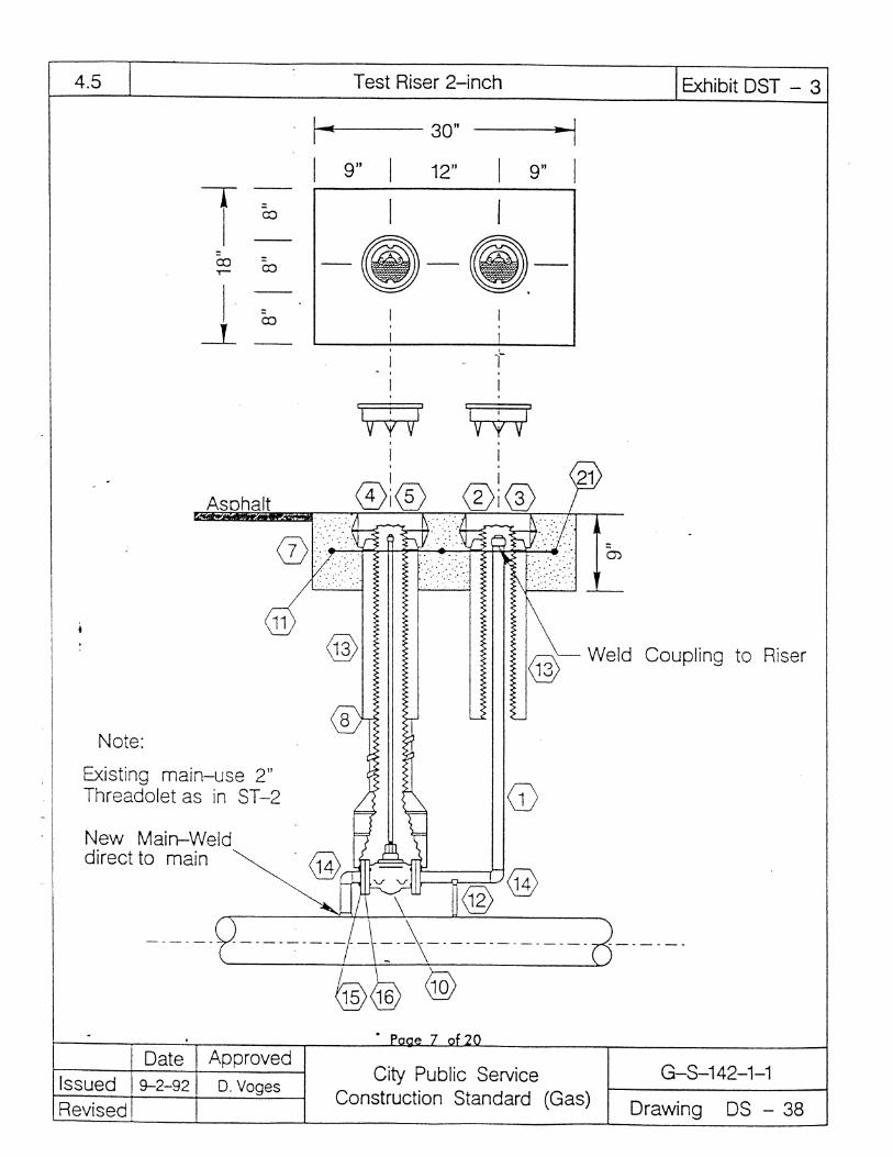
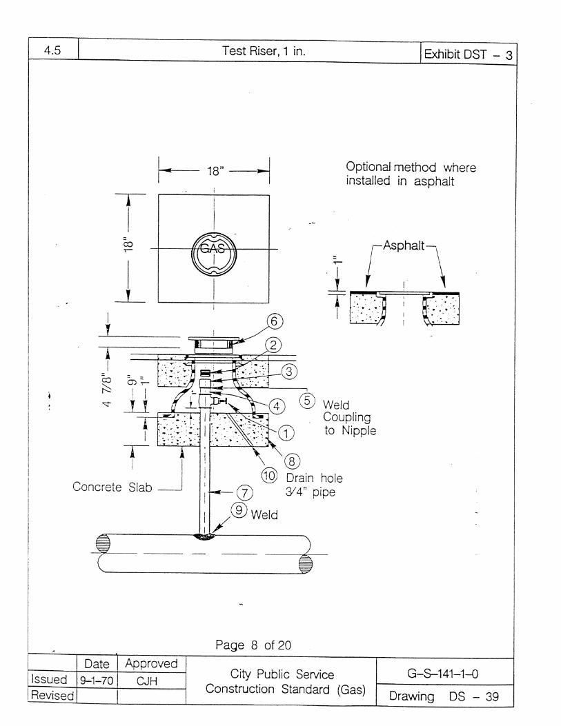
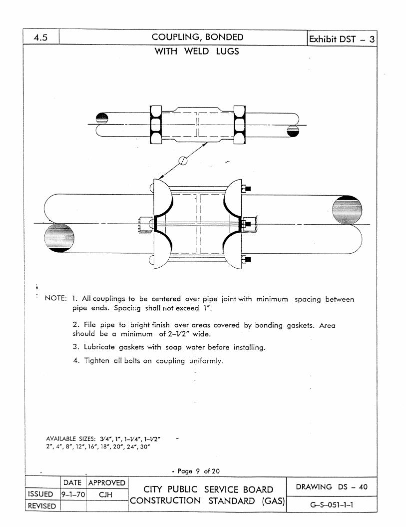
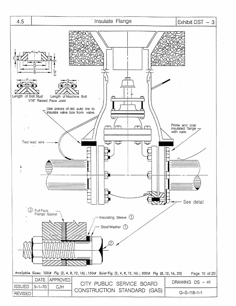
EXHIBIT GAS-3
DESIGN STANDARS FOR
STEEL GAS PIPING