Tools & sst (special service tools) daihatsu training center

TRANSFER
SECTIONTFCONTENTS
PREPARATION ...............................................................2Special Service Tools ..................................................2Commercial Service Tools ...........................................3
NOISE, VIBRATION AND HARSHNESS (NVH)TROUBLESHOOTING .....................................................5
NVH Troubleshooting Chart.........................................5TRANSFER ...............................................................5
DESCRIPTION .................................................................6Cross-sectional View ...................................................6
ON-VEHICLE SERVICE ..................................................7Replacing Oil Seal .......................................................7
CENTER CASE OIL SEAL..........................................7SHIFT SHAFT OIL SEAL............................................8REAR OIL SEAL........................................................8
Position Switch Check .................................................9REMOVAL AND INSTALLATION .................................10
Removal.....................................................................10Installation..................................................................10
M/T MODEL ............................................................10A/T MODEL.............................................................10
OVERHAUL ...................................................................11Transfer Gear Control................................................11Case Components .....................................................12Gear Components .....................................................13Shift Control Components .........................................14
DISASSEMBLY ..............................................................15REPAIR FOR COMPONENT PARTS ...........................20
Mainshaft ...................................................................20DISASSEMBLY........................................................20INSPECTION...........................................................21ASSEMBLY .............................................................22
Front Drive Shaft .......................................................22DISASSEMBLY........................................................22INSPECTION...........................................................22ASSEMBLY .............................................................22
Counter Gear .............................................................23DISASSEMBLY........................................................23INSPECTION...........................................................23
ASSEMBLY .............................................................23Main Gear ..................................................................23
DISASSEMBLY........................................................23INSPECTION...........................................................24ASSEMBLY .............................................................24
Front Case .................................................................25REMOVAL...............................................................25INSTALLATION........................................................25
Front Case Cover ......................................................25REMOVAL...............................................................25INSTALLATION........................................................25
Bearing Retainer........................................................26REMOVAL...............................................................26INSTALLATION........................................................26
Center Case...............................................................26REMOVAL...............................................................26INSTALLATION........................................................26
Rear Case..................................................................26REMOVAL...............................................................26INSTALLATION........................................................27
Shift Control Components .........................................27INSPECTION...........................................................27
ASSEMBLY ....................................................................29SERVICE DATA AND SPECIFICATIONS (SDS) .........37
General Specifications...............................................37Inspection and Adjustment ........................................37
CLEARANCE BETWEEN FRONT DRIVESPROCKET AND 2-4 COUPLING SLEEVE................37GEAR END PLAY ....................................................37CLEARANCE BETWEEN BAULK RING ANDCLUTCH GEAR .......................................................37
Available Shim ...........................................................37COUNTER GEAR REAR BEARING...........................37
Available Snap Ring ..................................................38MAINSHAFT FRONT BEARING ................................38MAIN GEAR BEARING.............................................38MAINSHAFT REAR BEARING ..................................38
GI
MA
EM
LC
EC
FE
CL
MT
AT
PD
AX
SU
BR
ST
RS
BT
HA
SC
EL
IDX
Special Service ToolsNGTF0001
The actual shapes of Kent-Moore tools may differ from those of special service tools illustrated here.
Tool number(Kent-Moore No.)Tool name
Description
KV38108300( — )Companion Flangewrench
NT771
Removing companion flange nutInstalling companion flange nut
ST30021000(J22912-01)Puller
NT411
Removing counter gear front bearing(Use with ST36710010)Removing L & H huba: 110 mm (4.33 in) dia.b: 68 mm (2.68 in) dia.
ST30031000(J22912-01)Puller
NT411
Removing counter gear rear bearing(Use with ST36710010)a: 90 mm (3.54 in) dia.b: 50 mm (1.97 in) dia.
ST33290001(J25810-A)Puller
NT414
Removing center case oil sealRemoving rear oil seala: 250 mm (9.84 in)b: 160 mm (6.30 in)
ST33051001(J22888)Puller
NT657
Removing companion flangea: 135 mm (5.31 in)b: 100 mm (3.94 in)c: 130 mm (5.12 in)
ST307200001 (J25273)2 (J25405)Drift
NT658
1 Installing center case oil seal2 Installing rear oil seala: 77 mm (3.03 in) dia.b: 55.5 mm (2.185 in) dia.
PREPARATIONSpecial Service Tools
TF-2

Tool number(Kent-Moore No.)Tool name
Description
ST36710010( — )Drift
NT063
Removing counter gear front bearing(Use with ST30021000)Removing counter gear rear bearing(Use with ST30031000)a: 34.5 mm (1.358 in) dia.
ST33061000(J8107-2)Drift
NT116
Removing main gear bearinga: 28.5 mm (1.122 in) dia.b: 38 mm (1.50 in) dia.
ST306130001 (J25742-3)2 (J34339)Drift
NT073
1 Installing main gear bearing2 Installing front case cover oil seala: 72 mm (2.83 in) dia.b: 48 mm (1.89 in) dia.
(J35864)Drift
NT117
Installing shift shaft oil seala: 26 mm (1.02 in) dia.b: 20 mm (0.79 in) dia.c: 150 mm (5.91 in)
(J26092)Drift
NT065
Seating counter gear assemblya: 44.5 mm (1.752 in) dia.b: 38.5 mm (1.516 in) dia.
(J34291)Shim setting gauge set
NT101
Selecting counter gear rear bearing shim
(J34291-20)Plunger-shim settinggauge
NT118
Selecting counter gear rear bearing shim
Commercial Service ToolsNGTF0002
The actual shapes of Kent-Moore tools may differ from those of special service tools illustrated here.
Tool name Description
Puller
NT077
Removing front drive shaft front bearingRemoving front drive shaft rear bearingRemoving main gear bearing
GI
MA
EM
LC
EC
FE
CL
MT
AT
PD
AX
SU
BR
ST
RS
BT
HA
SC
EL
IDX
PREPARATIONSpecial Service Tools (Cont’d)
TF-3

Tool name Description
Drift
NT117
1 Installing mainshaft rear bearing2 Installing L & H hub1 a: 50 mm (1.97 in) dia.
b: 42 mm (1.65 in) dia.c: 180 mm (7.09 in)
2 a: 60 mm (2.36 in) dia.b: 50 mm (1.97 in) dia.c: 60 mm (2.36 in)
PREPARATIONCommercial Service Tools (Cont’d)
TF-4

NGTF0039
NVH Troubleshooting ChartNGTF0039S01
Use the chart below to help you find the cause of the symptom. The numbers indicate the order of inspection.If necessary, repair or replace these parts.
TRANSFERNGTF0039S0101
Reference page
Ref
erto
MA
-37,
(″C
heck
ing
Tran
sfer
Flu
id″,
″CH
AS
SIS
AN
DB
OD
YM
AIN
TE
NA
NC
E″)
.
TF
-12
TF
-12
TF
-12,
TF
-14
TF
-14
TF
-13
TF
-13
TF
-13
TF
-13
SUSPECTED PARTS(Possible cause)
FLU
ID(L
evel
low
)
FLU
ID(W
rong
)
FLU
ID(L
evel
too
high
)
LIQ
UID
GA
SK
ET
(Dam
aged
)
OIL
SE
AL
(Wor
nor
dam
aged
)
CH
EC
KS
PR
ING
AN
DC
HE
CK
BA
LL(W
orn
dam
aged
)
SH
IFT
FO
RK
(Wor
n)
GE
AR
(Wor
nor
dam
aged
)
Bea
ring
(Wor
nor
dam
aged
)
BA
ULK
RIN
G(W
orn
orda
mag
ed)
SH
IFT
ING
INS
ER
T(D
amag
ed)
Symptom
Noise 1 2 3 3
Fluid leakage 3 1 2 2
Hard to shift or will not shift 1 1 2 2
Jumps out of gear 1 2 2
GI
MA
EM
LC
EC
FE
CL
MT
AT
PD
AX
SU
BR
ST
RS
BT
HA
SC
EL
IDX
NOISE, VIBRATION AND HARSHNESS (NVH) TROUBLESHOOTINGNVH Troubleshooting Chart
TF-5

Cross-sectional ViewNGTF0003
ATF021
DESCRIPTIONCross-sectional View
TF-6

SMT844D
Replacing Oil SealNGTF0004
CENTER CASE OIL SEALNGTF0004S01
1. Remove front propeller shaft. Refer to PD-7, (“Removal andInstallation”, “PROPELLER SHAFT”).
2. Remove companion flange nut.
SMT486A
3. Remove companion flange.
AMT086
4. Remove center case oil seal.5. Install center case oil seal.I Before installing, apply multi-purpose grease to seal lip.6. Install companion flange.
SMT845D
7. Tighten companion flange nut.: 226 - 324 N·m (23 - 33 kg-m, 166 - 239 ft-lb)
8. Install front propeller shaft. Refer to PD-7, (“Removal andInstallation”, “PROPELLER SHAFT”).
GI
MA
EM
LC
EC
FE
CL
MT
AT
PD
AX
SU
BR
ST
RS
BT
HA
SC
EL
IDX
ON-VEHICLE SERVICEReplacing Oil Seal
TF-7

ATF007
SHIFT SHAFT OIL SEALNGTF0004S02
1. Remove front propeller shaft. Refer to PD-7, (“Removal andInstallation”, “PROPELLER SHAFT”).
2. Remove companion flange. Refer to “CENTER CASE OILSEAL”, TF-7.
3. Remove transfer control lever from transfer outer shift lever.Then remove outer shift lever.
SMT491A
4. Remove shift shaft oil seal.I Be careful not to damage cross shaft.
SMT492A
5. Install shift shaft oil seal.I Before installing, apply multi-purpose grease to seal lip.6. Install transfer control linkage.7. Install companion flange. Refer to “CENTER CASE OIL
SEAL”, TF-7.8. Install front propeller shaft. Refer to PD-7, (“Removal and
Installation”, “PROPELLER SHAFT”).
AMT087
REAR OIL SEALNGTF0004S03
1. Remove rear propeller shaft. Refer to PD-7, (“Removal andInstallation”, “PROPELLER SHAFT”).
2. Remove rear oil seal.
SMT494A
3. Install rear oil seal.I Before installing apply multi-purpose grease to seal lip.4. Install rear propeller shaft. Refer to PD-7, (“Removal and
Installation”, “PROPELLER SHAFT”).
ON-VEHICLE SERVICEReplacing Oil Seal (Cont’d)
TF-8
SMT790CA
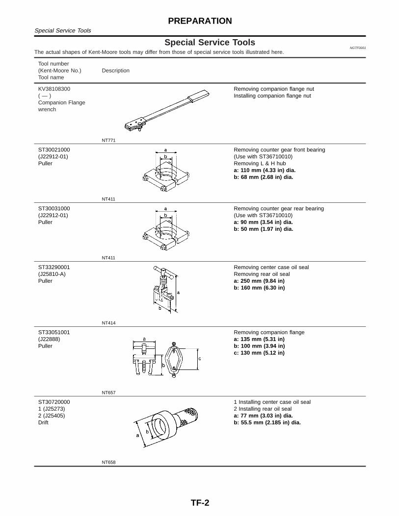
Position Switch CheckNGTF0042
Switch Gear Position Continuity
4WD Switch4WD Yes
Except 4WD NO
Neutral Position SwitchNeutral NO
Except Neutral Yes
GI
MA
EM
LC
EC
FE
CL
MT
AT
PD
AX
SU
BR
ST
RS
BT
HA
SC
EL
IDX
ON-VEHICLE SERVICEPosition Switch Check
TF-9
ATF020
ATF007
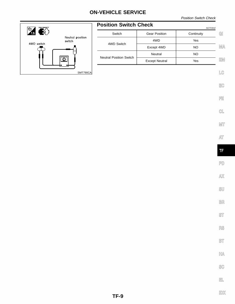
RemovalNGTF0006
1. Drain fluid from transfer, and drain oil from transmission.2. Remove front and rear propeller shaft. Refer to PD-7,
(“Removal and Installation”, “PROPELLER SHAFT”).Insert plug into rear oil seal after removing propeller shaft.
I Be careful not to damage spline, sleeve yoke and rear oilseal, when removing propeller shaft.
3. Remove torsion bar spring. Refer to SU-14, (“Torsion BarSpring”, “FRONT SUSPENSION”). Then remove secondcrossmember.
4. Remove exhaust front and rear tubes. Refer to FE-8,(“EXHAUST SYSTEM”).
5. Disconnect vehicle speed sensor, transfer neutral positionswitch and 4WD switch harness connectors.
6. Remove air breather hose.7. Remove transfer control lever from transfer outer shift lever.8. Separate transfer from transmission.WARNING:Support transfer while removing it.
SMT495A
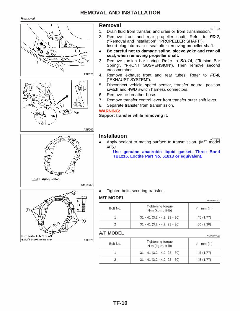
InstallationNGTF0007
I Apply sealant to mating surface to transmission. (M/T modelonly)
Use genuine anaerobic liquid gasket, Three BondTB1215, Loctite Part No. 51813 or equivalent.
ATF026
I Tighten bolts securing transfer.
M/T MODELNGTF0007S01
Bolt No.Tightening torqueN·m (kg-m, ft-lb)
� mm (in)
1 31 - 41 (3.2 - 4.2, 23 - 30) 45 (1.77)
2 31 - 41 (3.2 - 4.2, 23 - 30) 60 (2.36)
A/T MODELNGTF0007S02
Bolt No.Tightening torqueN·m (kg-m, ft-lb)
� mm (in)
1 31 - 41 (3.2 - 4.2, 23 - 30) 45 (1.77)
2 31 - 41 (3.2 - 4.2, 23 - 30) 45 (1.77)
REMOVAL AND INSTALLATIONRemoval
TF-10

Transfer Gear ControlNGTF0008
ATF027
GI
MA
EM
LC
EC
FE
CL
MT
AT
PD
AX
SU
BR
ST
RS
BT
HA
SC
EL
IDX
OVERHAULTransfer Gear Control
TF-11

Case ComponentsNGTF0009
ATF023
OVERHAULCase Components
TF-12

Gear ComponentsNGTF0010
ATF028
GI
MA
EM
LC
EC
FE
CL
MT
AT
PD
AX
SU
BR
ST
RS
BT
HA
SC
EL
IDX
OVERHAULGear Components
TF-13

Shift Control ComponentsNGTF0011
ATF025
OVERHAULShift Control Components
TF-14

NGTF0012
SMT846D
1. Remove companion flange nut.2. Remove companion flange.
SMT270A
3. Remove 4WD switch.4. Remove rear case.I Be careful not to damage the mating surface.
SMT435C
5. Remove oil cover and oil gutter.6. Remove snap ring and retainer ring from 2-4 shift rod.
SMT799CA
7. Using calipers, measure the difference between front drivesprocket and 2–4 coupling sleeve as outlined under measur-ing method bellow. If it is outside specifications, check frontdrive sprocket, 2–4 coupling sleeve, clutch gear, 2–4 shift forkand 2–4 fork rod for abnormalities. Replace faulty part(s) asrequired.Measuring method
Move Coupling sleeve until it is in contact withsprocket, then measure dimension A. Move couplingsleeve until it is in contact with clutch gear, then mea-sure dimension B. Obtain dimension difference Cbetween two measurements A and B.
C = A – BTo determine dimension A, measure at 3 or 4 differentpoints by rotating sprocket and obtain average value of3 or 4 measurements.
Specification C: Refer to TF-37.
GI
MA
EM
LC
EC
FE
CL
MT
AT
PD
AX
SU
BR
ST
RS
BT
HA
SC
EL
IDX
DISASSEMBLY
TF-15

SMT273A
8. Remove bolts securing bearing retainer.I This step is necessary to remove mainshaft from center
case.
SMT274A
9. Remove bolts securing center case to front case and thenseparate center case and front case.
SMT342A
10. Measure low gear end play.Standard:
0.2 - 0.35 mm (0.0079 - 0.0138 in)I If end play is beyond the maximum value, check low gear
and L & H hub for wear.
SMT275A
11. Disassemble center case assembly.a. Remove snap ring from mainshaft.
SMT757A
b. Pull out low gear with L & H hub.
DISASSEMBLY
TF-16

SMT758A
c. Remove needle bearing from main shaft.
SMT788C
d. Make sure of the direction of the drive chain before removingit. (It must be reinstalled in the same direction.)
SMT279A
e. Remove mainshaft, front drive and drive chain as a set bytapping front end of mainshaft and front drive shaft alternately.
I Be careful not to bend drive chain.
ATF019
12. Disassemble front case assembly.a. Remove transfer neutral position switch, plugs, check springs
and check balls.
ATF013
b. Remove lock pin from outer shift lever, then remove outer shiftlever.
GI
MA
EM
LC
EC
FE
CL
MT
AT
PD
AX
SU
BR
ST
RS
BT
HA
SC
EL
IDX
DISASSEMBLY
TF-17

SMT282A
c. Remove lock pin of inner shift lever and drive out cross shaftwith plug.
SMT283A
d. Remove 2-4 shift rod.
SMT284A
e. Remove L & H shift rod and fork assembly with couplingsleeve.
SMT286A
f. Remove needle bearing from main gear.
SMT287A
g. Remove bolts securing front case cover and then removecase.
DISASSEMBLY
TF-18
SMT759A
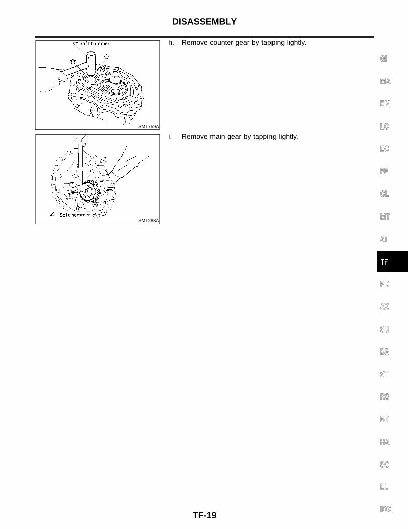
h. Remove counter gear by tapping lightly.
SMT288A
i. Remove main gear by tapping lightly.
GI
MA
EM
LC
EC
FE
CL
MT
AT
PD
AX
SU
BR
ST
RS
BT
HA
SC
EL
IDX
DISASSEMBLY
TF-19

SMT347A
MainshaftDISASSEMBLY
NGTF0013
1. Check front drive sprocket end play.Standard:
0.2 - 0.35 mm (0.0079 - 0.0138 in)I If end play is not within specification, check front drive
sprocket and clutch gear for wear.
SMT289A
2. Remove retainer ring, speedometer drive gear and steel ball.I Be careful not to lose the steel ball.
SMT290A
3. Remove snap ring and spacer.
SMT291A
4. Use a press to remove front drive sprocket with mainshaft rearbearing and clutch gear together.
5. Remove needle bearing.
SMT292A
6. Remove bearing retainer and then remove snap ring.
REPAIR FOR COMPONENT PARTSMainshaft
TF-20
SMT293A
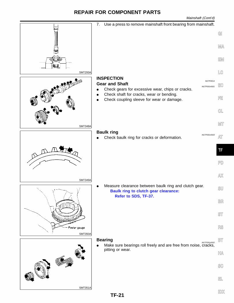
7. Use a press to remove mainshaft front bearing from mainshaft.
SMT348A
INSPECTIONNGTF0014
Gear and ShaftNGTF0014S01
I Check gears for excessive wear, chips or cracks.I Check shaft for cracks, wear or bending.I Check coupling sleeve for wear or damage.
SMT349A
Baulk ringNGTF0014S03
I Check baulk ring for cracks or deformation.
SMT350A
I Measure clearance between baulk ring and clutch gear.Baulk ring to clutch gear clearance:
Refer to SDS, TF-37.
SMT351A
BearingNGTF0014S02
I Make sure bearings roll freely and are free from noise, cracks,pitting or wear.
GI
MA
EM
LC
EC
FE
CL
MT
AT
PD
AX
SU
BR
ST
RS
BT
HA
SC
EL
IDX
REPAIR FOR COMPONENT PARTSMainshaft (Cont’d)
TF-21

SMT294A
ASSEMBLYNGTF0015
1. Press mainshaft front bearing onto mainshaft.I Pay special attention to its direction.
SMT295A
2. Select snap ring with proper thickness.Allowable clearance between snap ring and groove:
0 - 0.15 mm (0 - 0.0059 in)Available snap ring for mainshaft front bearing:
Refer to SDS, TF-38.3. Regarding to further procedures, refer to “ASSEMBLY”, TF-29.
SMT437C
Front Drive ShaftDISASSEMBLY
NGTF0016
I Using a gear puller, remove front drive shaft front and rearbearings
SMT357A
INSPECTIONNGTF0017
Sprocket and ShaftNGTF0017S01
I Check sprocket for excessive wear, chips or cracks.I Check shaft for cracks or wear.
BearingNGTF0017S02
I Make sure bearings roll freely and are free from noise, cracks,pitting or wear.
SMT438C
ASSEMBLYNGTF0018
I Press front drive shaft front and rear bearings onto front driveshaft.
REPAIR FOR COMPONENT PARTSMainshaft (Cont’d)
TF-22

AMT093
Counter GearDISASSEMBLY
NGTF0019
1. Press out counter gear front bearing.I Remove front sub-gear, dish plate and spacer (M/T model
only).
SMT301A
2. Press out counter gear rear bearing.I Remove rear sub-gear, dish plate and spacer (M/T model
only).
SMT358A
INSPECTIONNGTF0020
Gear and ShaftNGTF0020S01
I Check gears for excessive wear, chips or cracks.I Check shaft for cracks or wear.
BearingNGTF0020S02
I Make sure bearings roll freely and are free from noise, cracks,pitting or wear.
SMT439C
ASSEMBLYNGTF0021
1. Install front sub-gear, dish plate and spacer (M/T model only).2. Press on counter gear front bearing.3. Install rear sub-gear, dish plate and spacer (M/T model only).4. Press on counter gear rear bearing.
SMT304A
Main GearDISASSEMBLY
NGTF0022
Main Gear BearingNGTF0022S01
1. Remove snap ring.
GI
MA
EM
LC
EC
FE
CL
MT
AT
PD
AX
SU
BR
ST
RS
BT
HA
SC
EL
IDX
REPAIR FOR COMPONENT PARTSCounter Gear
TF-23
SMT305A
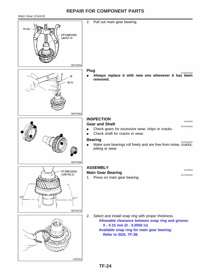
2. Pull out main gear bearing.
SMT306A
PlugNGTF0022S02
I Always replace it with new one whenever it has beenremoved.
SMT359A
INSPECTIONNGTF0023
Gear and ShaftNGTF0023S01
I Check gears for excessive wear, chips or cracks.I Check shaft for cracks or wear.
BearingNGTF0023S02
I Make sure bearings roll freely and are free from noise, cracks,pitting or wear.
SMT307A
ASSEMBLYNGTF0024
Main Gear BearingNGTF0024S01
1. Press on main gear bearing.
ATF014
2. Select and install snap ring with proper thickness.Allowable clearance between snap ring and groove:
0 - 0.15 mm (0 - 0.0059 in)Available snap ring for main gear bearing:
Refer to SDS, TF-38.
REPAIR FOR COMPONENT PARTSMain Gear (Cont’d)
TF-24
SMT309A
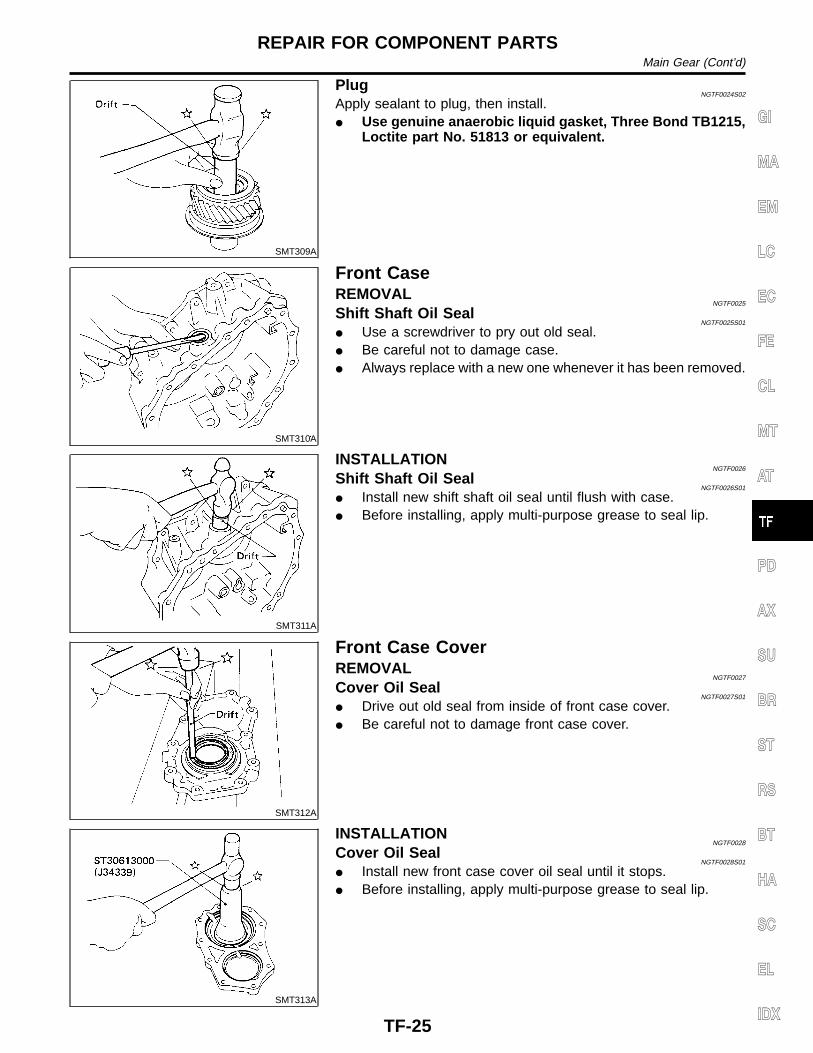
PlugNGTF0024S02
Apply sealant to plug, then install.I Use genuine anaerobic liquid gasket, Three Bond TB1215,
Loctite part No. 51813 or equivalent.
SMT310A
Front CaseREMOVAL
NGTF0025
Shift Shaft Oil SealNGTF0025S01
I Use a screwdriver to pry out old seal.I Be careful not to damage case.I Always replace with a new one whenever it has been removed.
SMT311A
INSTALLATIONNGTF0026
Shift Shaft Oil SealNGTF0026S01
I Install new shift shaft oil seal until flush with case.I Before installing, apply multi-purpose grease to seal lip.
SMT312A
Front Case CoverREMOVAL
NGTF0027
Cover Oil SealNGTF0027S01
I Drive out old seal from inside of front case cover.I Be careful not to damage front case cover.
SMT313A
INSTALLATIONNGTF0028
Cover Oil SealNGTF0028S01
I Install new front case cover oil seal until it stops.I Before installing, apply multi-purpose grease to seal lip.
GI
MA
EM
LC
EC
FE
CL
MT
AT
PD
AX
SU
BR
ST
RS
BT
HA
SC
EL
IDX
REPAIR FOR COMPONENT PARTSMain Gear (Cont’d)
TF-25
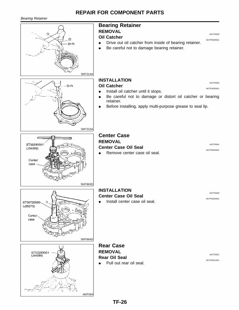
SMT314A
Bearing RetainerREMOVAL
NGTF0029
Oil CatcherNGTF0029S01
I Drive out oil catcher from inside of bearing retainer.I Be careful not to damage bearing retainer.
SMT315A
INSTALLATIONNGTF0030
Oil CatcherNGTF0030S01
I Install oil catcher until it stops.I Be careful not to damage or distort oil catcher or bearing
retainer.I Before installing, apply multi-purpose grease to seal lip.
SMT863D
Center CaseREMOVAL
NGTF0044
Center Case Oil SealNGTF0044S01
I Remove center case oil seal.
SMT864D
INSTALLATIONNGTF0045
Center Case Oil SealNGTF0045S01
I Install center case oil seal.
AMT094
Rear CaseREMOVAL
NGTF0031
Rear Oil SealNGTF0031S01
I Pull out rear oil seal.
REPAIR FOR COMPONENT PARTSBearing Retainer
TF-26
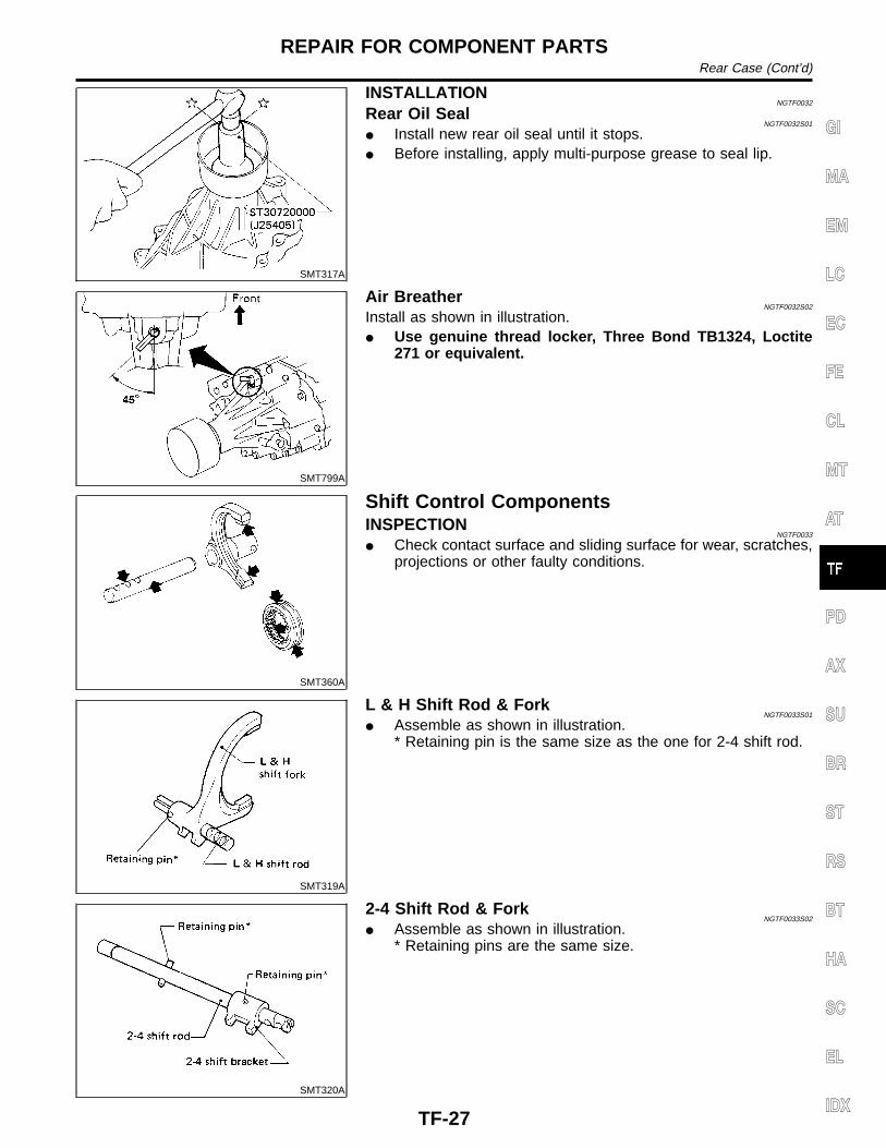
SMT317A
INSTALLATIONNGTF0032
Rear Oil SealNGTF0032S01
I Install new rear oil seal until it stops.I Before installing, apply multi-purpose grease to seal lip.
SMT799A
Air BreatherNGTF0032S02
Install as shown in illustration.I Use genuine thread locker, Three Bond TB1324, Loctite
271 or equivalent.
SMT360A
Shift Control ComponentsINSPECTION
NGTF0033
I Check contact surface and sliding surface for wear, scratches,projections or other faulty conditions.
SMT319A
L & H Shift Rod & ForkNGTF0033S01
I Assemble as shown in illustration.* Retaining pin is the same size as the one for 2-4 shift rod.
SMT320A
2-4 Shift Rod & ForkNGTF0033S02
I Assemble as shown in illustration.* Retaining pins are the same size.
GI
MA
EM
LC
EC
FE
CL
MT
AT
PD
AX
SU
BR
ST
RS
BT
HA
SC
EL
IDX
REPAIR FOR COMPONENT PARTSRear Case (Cont’d)
TF-27
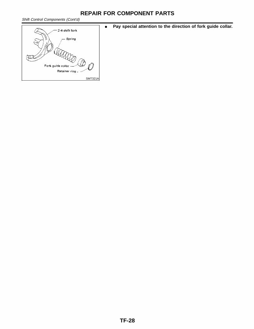
SMT321A
I Pay special attention to the direction of fork guide collar.
REPAIR FOR COMPONENT PARTSShift Control Components (Cont’d)
TF-28

NGTF0034
SMT323A
1. Assemble front case.a. Install main gear assembly by tapping lightly.
SMT325A
b. Apply sealant to the mating surface and bolts of front casecover, then attach it to the front case.
I Use genuine anaerobic liquid gasket, Three Bond TB1215,Loctite Part No. 51813 or equivalent.
I These ten bolts should be coated with sealant.Bolts A: 16 - 21 N·m (1.6 - 2.1 kg-m, 12 - 15 ft-lb)Bolts B: 19 - 24 N·m (1.9 - 2.4 kg-m, 14 - 17 ft-lb)
SMT326A
c. Apply ATF to needle bearing and install it into main gear.
SMT327A
d. Install counter gear assembly by tapping lightly.
SMT798A
e. Install cross shaft and inner shift lever.I When replacing cross shaft, outer shift lever or outer shift
lever lock pin, replace them as a set.
GI
MA
EM
LC
EC
FE
CL
MT
AT
PD
AX
SU
BR
ST
RS
BT
HA
SC
EL
IDX
ASSEMBLY
TF-29
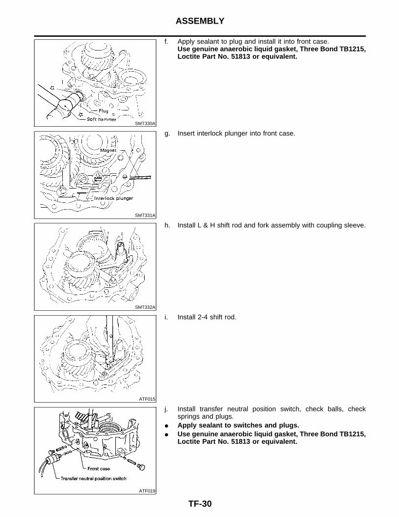
SMT330A
f. Apply sealant to plug and install it into front case.Use genuine anaerobic liquid gasket, Three Bond TB1215,Loctite Part No. 51813 or equivalent.
SMT331A
g. Insert interlock plunger into front case.
SMT332A
h. Install L & H shift rod and fork assembly with coupling sleeve.
ATF015
i. Install 2-4 shift rod.
ATF019
j. Install transfer neutral position switch, check balls, checksprings and plugs.
I Apply sealant to switches and plugs.I Use genuine anaerobic liquid gasket, Three Bond TB1215,
Loctite Part No. 51813 or equivalent.
ASSEMBLY
TF-30

SMT590A
2. Select counter gear rear bearing shim.a. Seat counter gear assembly.
SMT591A
b. Place J34291-1 (bridge), J34291-2 (legs) and J34291-5 (gaug-ing cylinder) on machined surface of center case, allowinggauging cylinder to rest on top outer portion of counter gearrear bearing. Lock gauging cylinder in place.
SMT592A
c. Insert J34291-20 (gauging plunger) into J34291-5 (gaugingcylinder).
SMT593A
d. Place bridge, legs, gauging cylinder and gauging plunger ontomachined surface of front case assembly, allowing gaugingplunger to drop until it contacts counter gear rear bearing mat-ing surface.
GI
MA
EM
LC
EC
FE
CL
MT
AT
PD
AX
SU
BR
ST
RS
BT
HA
SC
EL
IDX
ASSEMBLY
TF-31

SMT594A
e. Lock gauging plunger in place and use feeler gauge to mea-sure end play between gauging cylinder and gauging plunger.
f. Use measured distance to select correct counter gear rearbearing shim.
Allowable counter gear end play:0 - 0.2 mm (0 - 0.008 in)
Allowable counter gear rear bearing shim:Refer to SDS, TF-37.
SMT336A
3. Place suitable shim with grease on counter gear rear bearing.4. Apply ATF to each part in front case.
SMT406A
5. Assemble center case assembly.a. Install mainshaft on center case by tapping lightly.I Apply ATF to mainshaft front bearing.
SMT407A
b. Install bearing retainer.: 16 - 21 N·m (1.6 - 21 kg-m, 12 - 15 ft-lb)
ASSEMBLY
TF-32
SMT408A
SMT409A
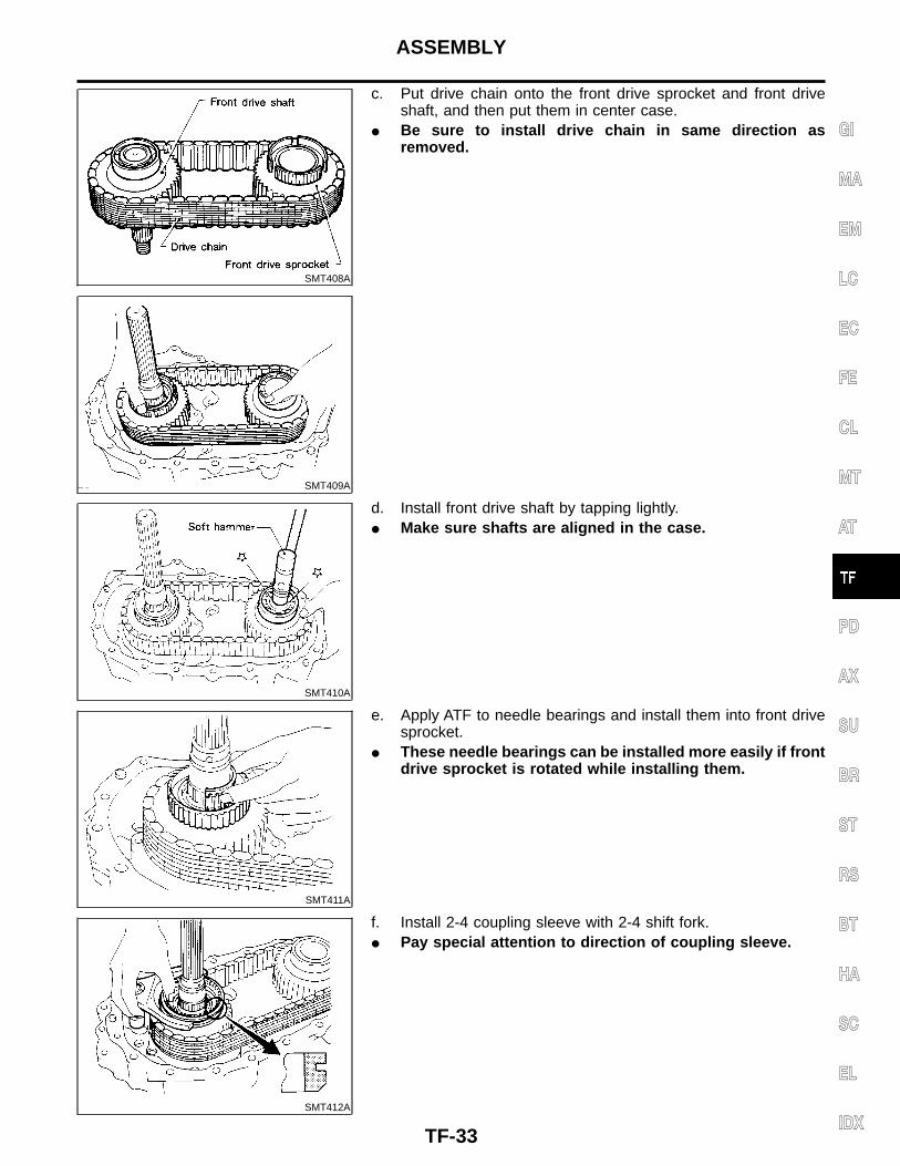
c. Put drive chain onto the front drive sprocket and front driveshaft, and then put them in center case.
I Be sure to install drive chain in same direction asremoved.
SMT410A
d. Install front drive shaft by tapping lightly.I Make sure shafts are aligned in the case.
SMT411A
e. Apply ATF to needle bearings and install them into front drivesprocket.
I These needle bearings can be installed more easily if frontdrive sprocket is rotated while installing them.
SMT412A
f. Install 2-4 coupling sleeve with 2-4 shift fork.I Pay special attention to direction of coupling sleeve.
GI
MA
EM
LC
EC
FE
CL
MT
AT
PD
AX
SU
BR
ST
RS
BT
HA
SC
EL
IDX
ASSEMBLY
TF-33
SMT353A
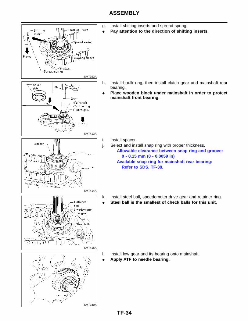
g. Install shifting inserts and spread spring.I Pay attention to the direction of shifting inserts.
SMT413A
h. Install baulk ring, then install clutch gear and mainshaft rearbearing.
I Place wooden block under mainshaft in order to protectmainshaft front bearing.
SMT414A
i. Install spacer.j. Select and install snap ring with proper thickness.
Allowable clearance between snap ring and groove:0 - 0.15 mm (0 - 0.0059 in)
Available snap ring for mainshaft rear bearing:Refer to SDS, TF-38.
SMT415A
k. Install steel ball, speedometer drive gear and retainer ring.I Steel ball is the smallest of check balls for this unit.
SMT340A
l. Install low gear and its bearing onto mainshaft.I Apply ATF to needle bearing.
ASSEMBLY
TF-34

SMT760A
m. Install L & H hub and snap ring to mainshaft.I Pay attention to direction of L & H hub.
SMT342A
n. Measure low gear end play.Standard:
0.2 - 0.35 mm (0.0079 - 0.0138 in)
SMT343A
6. Apply sealant to mating surface of center case then attach tofront case and tighten bolts.
I Use genuine anaerobic liquid gasket, Three Bond TB1215,Loctite Part No. 51813 or equivalent.
SMT272A
7. Install snap ring to 2-4 shift rod.
SMT344A
8. Install oil gutter and oil cover.9. Apply ATF to each part in center case.
GI
MA
EM
LC
EC
FE
CL
MT
AT
PD
AX
SU
BR
ST
RS
BT
HA
SC
EL
IDX
ASSEMBLY
TF-35

SMT497C
10. Apply sealant to mating surface of rear case then attach it tocenter case and tighten bolts.
I Use genuine anaerobic liquid gasket, Three Bond TB1215,Loctite Part No. 51813 or equivalent.
11. Install 4WD switch.I Apply sealant to switch threads.I Use genuine anaerobic liquid gasket, Three Bond TB1215,
Loctite Part No. 51813 or equivalent.
ASSEMBLY
TF-36
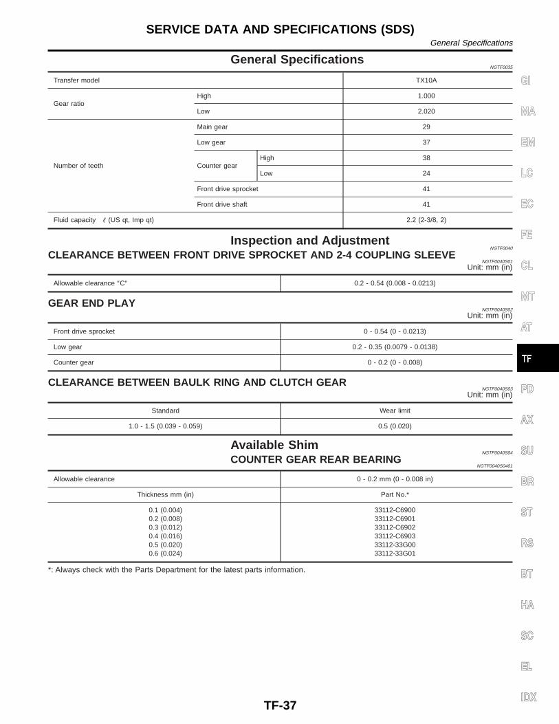
General SpecificationsNGTF0035
Transfer model TX10A
Gear ratioHigh 1.000
Low 2.020
Number of teeth
Main gear 29
Low gear 37
Counter gearHigh 38
Low 24
Front drive sprocket 41
Front drive shaft 41
Fluid capacity � (US qt, Imp qt) 2.2 (2-3/8, 2)
Inspection and AdjustmentNGTF0040
CLEARANCE BETWEEN FRONT DRIVE SPROCKET AND 2-4 COUPLING SLEEVENGTF0040S01
Unit: mm (in)
Allowable clearance ″C″ 0.2 - 0.54 (0.008 - 0.0213)
GEAR END PLAYNGTF0040S02
Unit: mm (in)
Front drive sprocket 0 - 0.54 (0 - 0.0213)
Low gear 0.2 - 0.35 (0.0079 - 0.0138)
Counter gear 0 - 0.2 (0 - 0.008)
CLEARANCE BETWEEN BAULK RING AND CLUTCH GEARNGTF0040S03
Unit: mm (in)
Standard Wear limit
1.0 - 1.5 (0.039 - 0.059) 0.5 (0.020)
Available ShimNGTF0040S04
COUNTER GEAR REAR BEARINGNGTF0040S0401
Allowable clearance 0 - 0.2 mm (0 - 0.008 in)
Thickness mm (in) Part No.*
0.1 (0.004)0.2 (0.008)0.3 (0.012)0.4 (0.016)0.5 (0.020)0.6 (0.024)
33112-C690033112-C690133112-C690233112-C690333112-33G0033112-33G01
*: Always check with the Parts Department for the latest parts information.
GI
MA
EM
LC
EC
FE
CL
MT
AT
PD
AX
SU
BR
ST
RS
BT
HA
SC
EL
IDX
SERVICE DATA AND SPECIFICATIONS (SDS)General Specifications
TF-37

Available Snap RingNGTF0040S05
MAINSHAFT FRONT BEARINGNGTF0040S0501
Allowable clearance 0 - 0.15 mm (0 - 0.0059 in)
Thickness mm (in) Part No.*
3.10 (0.1220)3.19 (0.1256)3.28 (0.1291)
33138-73P1033138-73P1133138-73P12
*: Always check with the Parts Department for the latest parts information.
MAIN GEAR BEARINGNGTF0040S0502
Allowable clearance 0 - 0.15 mm (0 - 0.0059 in)
Thickness mm (in) Part No.*
2.60 (0.1024)2.69 (0.1059)2.78 (0.1094)
33114-73P0033114-73P0133114-73P02
*: Always check with the Parts Department for the latest parts information.
MAINSHAFT REAR BEARINGNGTF0040S0503
Allowable clearance 0 - 0.15 mm (0 - 0.0059 in)
Thickness mm (in) Part No.*
1.80 (0.0709)1.89 (0.0744)1.98 (0.0780)2.07 (0.0815)2.16 (0.0850)
33138-73P2033138-73P2133138-73P2233138-73P2333138-73P24
*: Always check with the Parts Department for the latest parts information.
SERVICE DATA AND SPECIFICATIONS (SDS)Available Snap Ring
TF-38