INTRODUCTION - automotrizenvideo.com file... Use of Special Service Tools (SST) and Special Service...
51
INTRODUCTION – HOW TO USE THIS MANUAL IN–1 IN HOW TO USE THIS MANUAL GENERAL INFORMATION 1. GENERAL DESCRIPTION (a) This manual is written in accordance with SAE J2008. (1) Diagnosis (2) Removing / Installing, Replacing, Disassembling / Reassembling, Checking and Adjusting (3) Final Inspection (b) The following procedures are omitted from this manual. However, these procedures must be performed. (1) Use a jack or lift to perform operations. (2) Clean all removed parts. (3) Perform a visual check. 2. INDEX (a) An alphabetical INDEX section is provided at the end of the manual as a reference to help you find the item to be repaired. 3. PREPARATION (a) Use of Special Service Tools (SST) and Special Service Materials (SSM) may be required, depending on the repair procedure. Be sure to use SST and SSM when they are required and follow the working procedures properly. A list of SST and SSM is in the "Preparation" section of this manual. 4. REPAIR PROCEDURES (a) A component illustration is placed under the title where necessary.
Transcript of INTRODUCTION - automotrizenvideo.com file... Use of Special Service Tools (SST) and Special Service...

INTRODUCTION – HOW TO USE THIS MANUAL IN–1
IN
HOW TO USE THIS MANUALGENERAL INFORMATION1. GENERAL DESCRIPTION
(a) This manual is written in accordance with SAE J2008.(1) Diagnosis(2) Removing / Installing, Replacing, Disassembling
/ Reassembling, Checking and Adjusting(3) Final Inspection
(b) The following procedures are omitted from this manual. However, these procedures must be performed.(1) Use a jack or lift to perform operations.(2) Clean all removed parts.(3) Perform a visual check.
2. INDEX(a) An alphabetical INDEX section is provided at the
end of the manual as a reference to help you find the item to be repaired.
3. PREPARATION(a) Use of Special Service Tools (SST) and Special
Service Materials (SSM) may be required, depending on the repair procedure. Be sure to use SST and SSM when they are required and follow the working procedures properly. A list of SST and SSM is in the "Preparation" section of this manual.
4. REPAIR PROCEDURES(a) A component illustration is placed under the title
where necessary.
IN–2 INTRODUCTION – HOW TO USE THIS MANUAL
IN
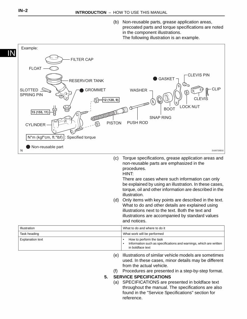
(b) Non-reusable parts, grease application areas, precoated parts and torque specifications are noted in the component illustrations. The following illustration is an example.
(c) Torque specifications, grease application areas and non-reusable parts are emphasized in the procedures.HINT:There are cases where such information can only be explained by using an illustration. In these cases, torque, oil and other information are described in the illustration.
(d) Only items with key points are described in the text. What to do and other details are explained using illustrations next to the text. Both the text and illustrations are accompanied by standard values and notices.
(e) Illustrations of similar vehicle models are sometimes used. In these cases, minor details may be different from the actual vehicle.
(f) Procedures are presented in a step-by-step format.5. SERVICE SPECIFICATIONS
(a) SPECIFICATIONS are presented in boldface text throughout the manual. The specifications are also found in the "Service Specifications" section for reference.
FILTER CAP
FLOAT
RESERVOIR TANK
SLOTTED
SPRING PIN
CYLINDER PISTON PUSH ROD
SNAP RING
BOOTLOCK NUT
CLEVIS
CLIP
CLEVIS PIN
WASHER
: Specified torqueN*m (kgf*cm, ft.*lbf)
Non-reusable part
GASKET
GROMMET
12 (120, 9)
15 (155, 11)
Example:
D100720E02
Illustration What to do and where to do it
Task heading What work will be performed
Explanation text • How to perform the task• Information such as specifications and warnings, which are written
in boldface text
INTRODUCTION – HOW TO USE THIS MANUAL IN–3
IN
6. TERM DEFINITIONS
7. INTERNATIONAL SYSTEM OF UNITS(a) The units used in this manual comply with the
International System of Units (SI) standard. Units from the metric system and English system are also provided.Example:Torque: 30 N*m (310 kgf*cm, 22 ft.*lbf)
CAUTION Possibility of injury to you or other people.
NOTICE Possibility of damage to components being repaired.
HINT Provides additional information to help you perform repairs.
IN–4 INTRODUCTION – IDENTIFICATION INFORMATION
IN
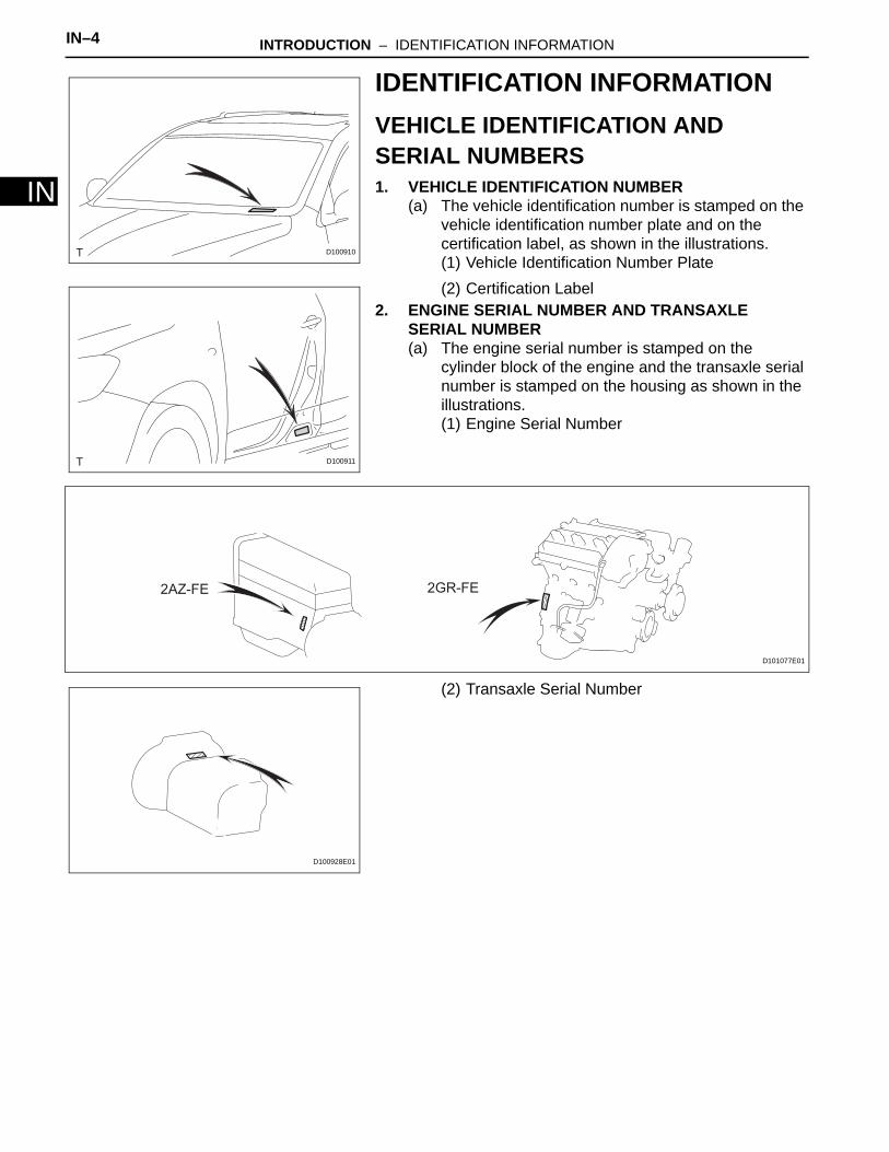
IDENTIFICATION INFORMATIONVEHICLE IDENTIFICATION AND SERIAL NUMBERS1. VEHICLE IDENTIFICATION NUMBER
(a) The vehicle identification number is stamped on the vehicle identification number plate and on the certification label, as shown in the illustrations.(1) Vehicle Identification Number Plate(2) Certification Label
2. ENGINE SERIAL NUMBER AND TRANSAXLE SERIAL NUMBER(a) The engine serial number is stamped on the
cylinder block of the engine and the transaxle serial number is stamped on the housing as shown in the illustrations.(1) Engine Serial Number
(2) Transaxle Serial Number
D100910
D100911
2AZ-FE 2GR-FE
D101077E01
D100928E01

INTRODUCTION – REPAIR INSTRUCTION IN–5
IN
REPAIR INSTRUCTIONPRECAUTION1. BASIC REPAIR HINT
(a) HINTS ON OPERATIONS
1 Attire • Always wear a clean uniform.• A hat and safety shoes must be worn.
2 Vehicle protection Prepare a grille cover, fender cover, seat cover and floor mat before starting the operation.
3 Safe operation • When working with 2 or more persons, be sure to check safety for one another.• When working with the engine running, make sure to provide ventilation for exhaust
fumes in the workshop.• If working on high temperature, high pressure, rotating, moving, or vibrating parts,
wear appropriate safety equipment and take extra care not to injure yourself or others.
• When jacking up the vehicle, be sure to support the specified location with a safety stand.
• When lifting up the vehicle, use appropriate safety equipment.
4 Preparation of tools and measuring gauge
Before starting the operation, prepare a tool stand, SST, gauge, oil and parts for replacement.
5 Removal and installation, disassembly and assembly operations
• Diagnose with a thorough understanding of proper procedures and of the reported problem.
• Before removing parts, check the general condition of the assembly and for deformation and damage.
• When the assembly is complicated, take notes. For example, note the total number of electrical connections, bolts, or hoses removed. Add matchmarks to ensure reassembly of components to their original positions. Temporarily mark hoses and their fittings if needed.
• Clean and wash the removed parts if necessary and assemble them after a thorough check.
1
2
46
3
5
3
D100912E01

IN–6 INTRODUCTION – REPAIR INSTRUCTION
IN(b) JACKING UP AND SUPPORTING VEHICLE
(1) Care must be taken when jacking up and supporting the vehicle. Be sure to lift and support the vehicle at the proper locations.
(c) PRECOATED PARTS(1) Precoated parts are bolts and nuts that are
coated with a seal lock adhesive at the factory.(2) If a precoated part is retightened, loosened or
moved in any way, it must be recoated with the specified adhesive.
(3) When reusing a precoated part, clean off the old adhesive and dry the part with compressed air. Then apply new seal lock adhesive appropriate to that part.
(4) Some seal lock agents harden slowly. You may have to wait for the seal lock adhesive to harden.
(d) GASKETS(1) When necessary, use a sealer on gaskets to
prevent leaks.(e) BOLTS, NUTS AND SCREWS
(1) Carefully follow all the specifications for tightening torques. Always use a torque wrench.
(f) FUSES(1) When inspecting a fuse, check that the wire of
the fuse is not broken.(2) When replacing fuses, be sure that the new fuse
has the correct amperage rating. Do not exceed the rating or use one with a lower rating.
6 Removed parts • Place removed parts in a separate box to avoid mixing them up with new parts or contaminating new parts.
• For non-reusable parts such as gaskets, O-rings, and self-locking nuts, replace them with new ones as instructed in this manual.
• Retain the removed parts for customer inspection, if requested.
Seal Lock Adhesive
D100721E01
INCORRECT CORRECT
D100722E01
Illustration Symbol Part Name Abbreviation
FUSE FUSE
MEDIUM CURRENT FUSE M-FUSE
INTRODUCTION – REPAIR INSTRUCTION IN–7
IN
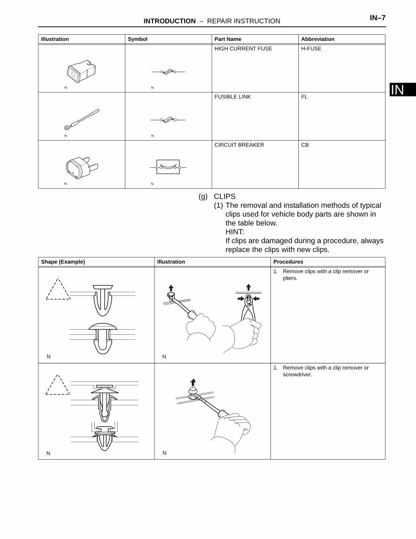
(g) CLIPS(1) The removal and installation methods of typical
clips used for vehicle body parts are shown in the table below.HINT:If clips are damaged during a procedure, always replace the clips with new clips.
HIGH CURRENT FUSE H-FUSE
FUSIBLE LINK FL
CIRCUIT BREAKER CB
Illustration Symbol Part Name Abbreviation
Shape (Example) Illustration Procedures
1. Remove clips with a clip remover or pliers.
1. Remove clips with a clip remover or screwdriver.

IN–8 INTRODUCTION – REPAIR INSTRUCTION
IN
(h) CLAWS(1) The removal and installation methods of typical
claws used for vehicle body parts are shown in the table below.HINT:If claws of caps or covers are damaged during a procedure, always replace the caps or covers with new ones.
1. Remove clips with a wide scraper to prevent panel damage.
1. Remove clips by pushing the center pin through and prying out the shell.
1. Remove clips by unscrewing the center pin and prying out the shell.
1. Remove the clip by prying out the pin and then prying out the shell.
Shape (Example) Illustration Procedures
INTRODUCTION – REPAIR INSTRUCTION IN–9
IN
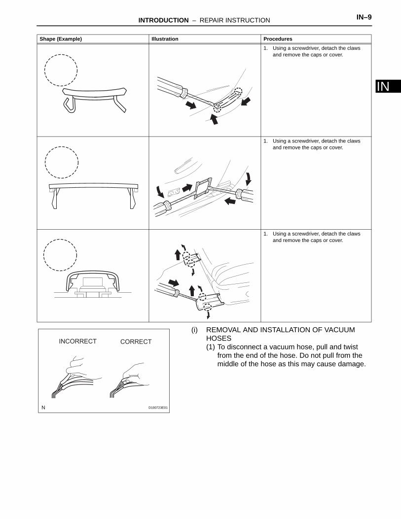
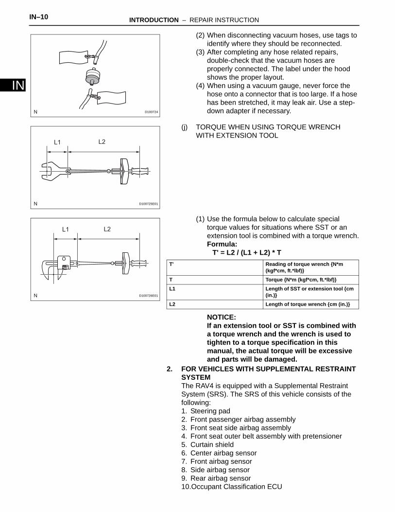
(i) REMOVAL AND INSTALLATION OF VACUUM HOSES(1) To disconnect a vacuum hose, pull and twist
from the end of the hose. Do not pull from the middle of the hose as this may cause damage.
Shape (Example) Illustration Procedures
1. Using a screwdriver, detach the claws and remove the caps or cover.
1. Using a screwdriver, detach the claws and remove the caps or cover.
1. Using a screwdriver, detach the claws and remove the caps or cover.
INCORRECT CORRECT
D100723E01
IN–10 INTRODUCTION – REPAIR INSTRUCTION
IN
(2) When disconnecting vacuum hoses, use tags to identify where they should be reconnected.
(3) After completing any hose related repairs, double-check that the vacuum hoses are properly connected. The label under the hood shows the proper layout.
(4) When using a vacuum gauge, never force the hose onto a connector that is too large. If a hose has been stretched, it may leak air. Use a step-down adapter if necessary.
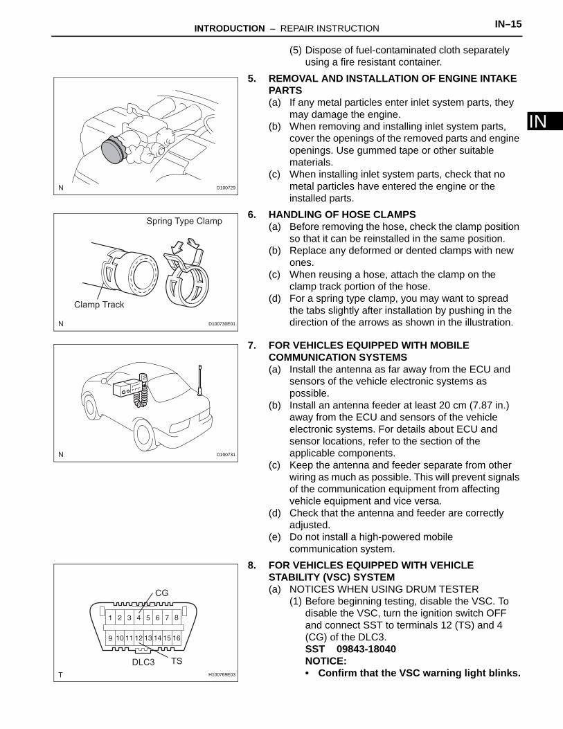
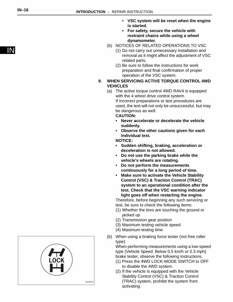
(j) TORQUE WHEN USING TORQUE WRENCH WITH EXTENSION TOOL
(1) Use the formula below to calculate special torque values for situations where SST or an extension tool is combined with a torque wrench.Formula:
T' = L2 / (L1 + L2) * T
NOTICE:If an extension tool or SST is combined with a torque wrench and the wrench is used to tighten to a torque specification in this manual, the actual torque will be excessive and parts will be damaged.
2. FOR VEHICLES WITH SUPPLEMENTAL RESTRAINT SYSTEMThe RAV4 is equipped with a Supplemental Restraint System (SRS). The SRS of this vehicle consists of the following:1. Steering pad2. Front passenger airbag assembly3. Front seat side airbag assembly4. Front seat outer belt assembly with pretensioner5. Curtain shield6. Center airbag sensor7. Front airbag sensor8. Side airbag sensor9. Rear airbag sensor10.Occupant Classification ECU
D100724
L2L1
D100725E01
L1 L2
D100726E01
T' Reading of torque wrench N*m (kgf*cm, ft.*lbf)
T Torque N*m (kgf*cm, ft.*lbf)
L1 Length of SST or extension tool cm (in.)
L2 Length of torque wrench cm (in.)

INTRODUCTION – REPAIR INSTRUCTION IN–11
IN
CAUTION:• Failure to carry out service procedures in the
correct sequence could cause SRS parts to unexpectedly deploy and possibly lead to serious injuries. Furthermore, if a mistake is made when servicing SRS parts, they may fail to operate when required. Before performing servicing (including installation/removal, inspection and replacement of parts), be sure to read the following precautions.
• Before starting work, wait at least 90 seconds after the ignition switch is turned OFF and after the cable of the negative (-) battery terminal is disconnected. (SRS parts are equipped with a backup power source. If work is started within 90 seconds of turning the ignition switch OFF and disconnecting the cable from the negative (-) battery terminal, SRS parts may deploy.)
• Do not expose SRS parts directly to hot air or flames.
NOTICE:• Malfunction symptoms of SRS parts are difficult
to confirm. DTCs are the most important source of information when troubleshooting. During troubleshooting, always confirm DTCs before disconnecting the cable from the negative (-) battery terminal.
• For minor collisions where SRS parts do not deploy, always inspect the SRS parts.
• Before performing repairs, remove airbag sensors as necessary if any kind of impact is likely to occur to an airbag sensor during repairs.
• Never use SRS parts from another vehicle. When replacing SRS parts, replace them with new ones.
• Never disassemble or attempt to repair SRS parts.• If an SRS part has been dropped, or if there are
any cracks, dents or other defects in the case, bracket or connector, replace the SRS part with a new one.
• Use an ohmmeter/voltmeter with high impedance (10 kΩ/V minimum) for troubleshooting the electrical circuits.
• Information labels are attached to the periphery of SRS parts. Follow the cautions and instructions on the labels.
• After work on SRS parts is completed, perform the SRS warning light check.

IN–12 INTRODUCTION – REPAIR INSTRUCTION
IN
• When the cable is disconnected from the negative (-) battery terminal, the memory settings of each system will be cleared. Because of this, be sure to write down the settings of each system before starting work. When work is finished, reset the settings of each system as before. Never use a backup power supply from outside the vehicle to avoid erasing the memory in a system.
(a) SPIRAL CABLE(1) The steering wheel must be fitted correctly to the
steering column with the spiral cable at the neutral position, as cable disconnection and other problems may occur. Refer to the information about correct installation of the steering wheel.
(b) AIRBAG ASSEMBLY(1) Airbag assembly with pad:
Always place a removed or new airbag assembly with the pad surface facing upward. Placing the airbag assembly with the airbag inflation direction facing downward could cause a serious accident if the airbag inflates. Also, do not place anything on top of the airbag assembly.
(2) Never measure the resistance of the airbag squib. This may cause the airbag to inflate, which could cause a serious injury.
(3) Grease or detergents of any kind should not be applied to the airbag assembly.
(4) Store the airbag assembly in an area where the ambient temperature is below 93°C (200°F), the humidity is not high and there is no electrical noise.
(5) When using electric welding anywhere on the vehicle, disconnect the airbag ECU connectors. These connectors contain shorting springs. This feature reduces the possibility of the airbag deploying due to currents entering the squib wiring.
(6) When disposing of the vehicle or the airbag assembly by itself, the airbag should be deployed using SST before disposal. Activate the airbag in a safe place away from electrical noise.
(c) SEAT OUTER BELT ASSEMBLY WITH PRETENSIONER(1) Never measure the resistance of the seat outer
belt. This may cause the pretensioner of the seat outer belt to activate, which could cause a serious injury.
(2) Never install the seat outer belt on another vehicle.

INTRODUCTION – REPAIR INSTRUCTION IN–13
IN
(3) Store the seat outer belt in an area where the ambient temperature is below 80°C (176°F), the humidity is not high and there is no electrical noise.
(4) When using electric welding anywhere on the vehicle, disconnect the airbag ECU connectors (2 pins). These connectors contain shorting springs. This feature reduces the possibility of the pretensioner deploying due to currents entering the squib wiring.
(5) When disposing of a vehicle or the seat outer belt by itself, the pretensioner should be activated before disposal. Activate the pretensioner in a safe place away from electrical noise.
(6) As the seat outer belt is hot after the pretensioner is activated, allow some time for it to cool down sufficiently before disposal. Never apply water to try to cool down the seat outer belt.
(7) Grease, detergents, oil or water should not be applied to the seat outer belt.
(d) AIRBAG SENSOR ASSEMBLY(1) Never reuse an airbag sensor assembly that has
been involved in a collision where the SRS has deployed.
(2) The connectors to the airbag sensor assembly should be connected or disconnected with the sensor placed on the floor. If the connectors are connected or disconnected while the airbag sensor assembly is not placed on the floor, the SRS may activate.
(3) Work must be started at least 90 seconds after the ignition switch is turned OFF and the cable is disconnected from the negative (-) battery terminal, even if only loosening the set bolts of the airbag sensor assembly.
(e) WIRE HARNESS AND CONNECTOR(1) The SRS wire harness is integrated with the
instrument panel wire harness assembly. All the connectors in the system are yellow. If the SRS wire harness becomes disconnected or the connector becomes broken, repair or replace it.
3. ELECTRONIC CONTROL(a) REMOVAL AND INSTALLATION OF BATTERY
TERMINALNOTICE:Certain systems need to be initialized after disconnecting and reconnecting the cable from the negative (-) battery terminal.(1) Before performing electronic work, disconnect
the cable from the negative (-) battery terminal to prevent component and wire damage caused by accidental short circuits.
Negative (-) Cable
Negative (-)
Battery
Terminal
D100727E01

IN–14 INTRODUCTION – REPAIR INSTRUCTION
IN
(2) When disconnecting the cable, turn the ignition switch OFF and headlight dimmer switch OFF and loosen the cable nut completely. Perform these operations without twisting or prying the cable. Then disconnect the cable.
(3) Clock settings, radio settings, audio system memory, DTCs and other data are erased when the cable is disconnected from the negative (-) battery terminal. Write down any necessary data before disconnecting the cable.
(b) HANDLING OF ELECTRONIC PARTS(1) Do not open the cover or case of the ECU
unless absolutely necessary. If the IC terminals are touched, the IC may be rendered inoperative by static electricity.
(2) Do not pull the wires when disconnecting electronic connectors. Pull the connector.
(3) Be careful not to drop electronic components, such as sensors or relays. If they are dropped on a hard surface, they should be replaced.
(4) When cleaning the engine with steam, protect the electronic components, air filter and emission-related components from water.
(5) Never use an impact wrench to remove or install temperature switches or temperature sensors.
(6) When measuring the resistance of a wire connector, insert the tester probe carefully to prevent terminals from bending.
4. REMOVAL AND INSTALLATION OF FUEL CONTROL PARTS(a) PLACE FOR REMOVING AND INSTALLING FUEL
SYSTEM PARTS(1) Work in a location with good air ventilation that
does not have welders, grinders, drills, electric motors, stoves, or any other ignition sources.
(2) Never work in a pit or near a pit as vaporized fuel will collect in those places.
(b) REMOVING AND INSTALLING FUEL SYSTEM PARTS(1) Prepare a fire extinguisher before starting the
operation.(2) To prevent static electricity, install a ground wire
to the fuel changer, vehicle and fuel tank, and do not spray the surrounding area with water. Be careful when performing work in this area, as the work surface will become slippery. Do not clean up gasoline spills with water, as this may cause the gasoline to spread, and possibly create a fire hazard.
(3) Avoid using electric motors, working lights and other electric equipment that can cause sparks or high temperatures.
(4) Avoid using iron hammers as they may create sparks.
INCORRECT
D100728E01
INTRODUCTION – REPAIR INSTRUCTION IN–15
IN
(5) Dispose of fuel-contaminated cloth separately using a fire resistant container.
5. REMOVAL AND INSTALLATION OF ENGINE INTAKE PARTS(a) If any metal particles enter inlet system parts, they
may damage the engine.(b) When removing and installing inlet system parts,
cover the openings of the removed parts and engine openings. Use gummed tape or other suitable materials.
(c) When installing inlet system parts, check that no metal particles have entered the engine or the installed parts.
6. HANDLING OF HOSE CLAMPS(a) Before removing the hose, check the clamp position
so that it can be reinstalled in the same position.(b) Replace any deformed or dented clamps with new
ones.(c) When reusing a hose, attach the clamp on the
clamp track portion of the hose.(d) For a spring type clamp, you may want to spread
the tabs slightly after installation by pushing in the direction of the arrows as shown in the illustration.
7. FOR VEHICLES EQUIPPED WITH MOBILE COMMUNICATION SYSTEMS(a) Install the antenna as far away from the ECU and
sensors of the vehicle electronic systems as possible.
(b) Install an antenna feeder at least 20 cm (7.87 in.) away from the ECU and sensors of the vehicle electronic systems. For details about ECU and sensor locations, refer to the section of the applicable components.
(c) Keep the antenna and feeder separate from other wiring as much as possible. This will prevent signals of the communication equipment from affecting vehicle equipment and vice versa.
(d) Check that the antenna and feeder are correctly adjusted.
(e) Do not install a high-powered mobile communication system.
8. FOR VEHICLES EQUIPPED WITH VEHICLE STABILITY (VSC) SYSTEM(a) NOTICES WHEN USING DRUM TESTER
(1) Before beginning testing, disable the VSC. To disable the VSC, turn the ignition switch OFF and connect SST to terminals 12 (TS) and 4 (CG) of the DLC3.SST 09843-18040NOTICE:• Confirm that the VSC warning light blinks.
D100729
Spring Type Clamp
Clamp Track
D100730E01
D100731
CG
TSDLC3
H100769E03
IN–16 INTRODUCTION – REPAIR INSTRUCTION
IN
• VSC system will be reset when the engine is started.
• For safety, secure the vehicle with restraint chains while using a wheel dynamometer.
(b) NOTICES OF RELATED OPERATIONS TO VSC(1) Do not carry out unnecessary installation and
removal as it might affect the adjustment of VSC related parts.
(2) Be sure to follow the instructions for work preparation and final confirmation of proper operation of the VSC system.
9. WHEN SERVICING ACTIVE TORQUE CONTROL 4WD VEHICLES(a) The active torque control 4WD RAV4 is equipped
with the 4 wheel drive control system.If incorrect preparations or test procedures are used, the test will not only be unsuccessful, but may be dangerous as well.CAUTION:• Never accelerate or decelerate the vehicle
suddenly.• Observe the other cautions given for each
individual test.NOTICE:• Sudden shifting, braking, acceleration or
deceleration is not allowed.• Do not use the parking brake while the
vehicle's wheels are rotating.• Do not perform the measurements
continuously for a long period of time.• Make sure to activate the Vehicle Stability
Control (VSC) & Traction Control (TRAC) system to an operational condition after the test. Check that the VSC warning indicator light goes off when restarting the engine.
Therefore, before beginning any such servicing or test, be sure to check the following items:(1) Whether the tires are touching the ground or
jacked up(2) Transmission gear position(3) Maximum testing vehicle speed(4) Maximum testing time
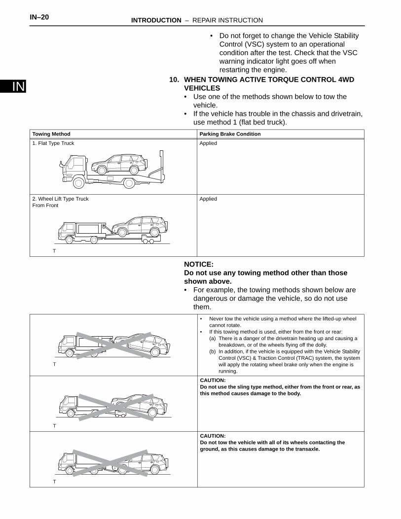
(b) When using a braking force tester (not free roller type):When performing measurements using a low-speed type (Vehicle Speed: Below 0.5 km/h or 0.3 mph) brake tester, observe the following instructions.(1) Press the 4WD LOCK-MODE SWITCH to OFF
to disable the 4WD system.(2) If the vehicle is equipped with the Vehicle
Stability Control (VSC) & Traction Control (TRAC) system, prohibit the system from activating.
LOCK
D101070

INTRODUCTION – REPAIR INSTRUCTION IN–17
IN
(3) Position the front wheels to be tested on the tester.
(4) Jack up the rear wheels.(5) Ensure that the vehicle does not move using
wires.(6) Shift the transmission shift lever to the "N"
position.(7) Idle the engine, operate the brake booster and
perform the test.CAUTION:The maximum driving time should be 1 minute.
(c) When using a braking force tester (free roller type):When performing measurements using a low-speed type (Vehicle Speed: Below 0.5 km/h or 0.3 mph) brake tester, observe the following instructions.(1) Press the 4WD LOCK-MODE SWITCH to turn it
OFF and disable the 4WD system.(2) If the vehicle is equipped with the Vehicle
Stability Control (VSC) & Traction Control (TRAC) system, prohibit the system from activating.
(3) Position the front wheels on the tester roller.(4) Position the rear wheels on the free roller.(5) Ensure that the vehicle does not move using
wires.(6) Shift the transmission shift lever to the "N"
position.(7) Idle the engine, operate the brake booster and
perform the test.CAUTION:The maximum driving time should be 1 minute.
(d) When using a speedometer (not free roller type):Observe the following instructions and then measure with the rear wheels.(1) Press the 4WD LOCK-MODE SWITCH to turn it
OFF and disable the 4WD system.(2) If the vehicle is equipped with the Vehicle
Stability Control (VSC) & Traction Control (TRAC) system, prohibit the system from activating.
D100914
LOCK
D101070
D100913
LOCK
D101070

IN–18 INTRODUCTION – REPAIR INSTRUCTION
IN
(3) Position the front wheels on the tester.(4) Jack up the rear wheels.(5) Ensure that the vehicle does not move using
wires.(6) Shift the transmission shift lever to the "D"
position.CAUTION:• The maximum speed should be less than
50 km/h (31 mph).• If the measurement is required with over
50 km/h (31 mph), remove the propeller shaft.
(e) When using a speedometer (free roller type):Observe the following instructions and then measure with the rear wheels.(1) Press the 4WD LOCK-MODE SWITCH to turn it
OFF and disable the 4WD system.(2) If the vehicle is equipped with the Vehicle
Stability Control (VSC) & Traction Control (TRAC) system, prohibit the system from activating.
(3) Position the front wheels on the tester roller.(4) Position the rear wheels on the free roller.(5) Ensure that the vehicle does not move using
wires.(6) Shift the transmission shift lever to the "D"
position.CAUTION:• The maximum speed should be less than
50 km/h (31 mph).• If the measurement is required with over
50 km/h (31 mph), remove the propeller shaft.
(f) Using chassis dynamometer
D100914
LOCK
D101070
D100913
Vehicle Condition Chassis dynamometer Type Note
2-Wheel Chassis Dynamometer • Remove the propeller shaft.• Remove the 4WD fuse from fuse box
during the test.NOTICE:After the test, reinstall the fuse, and then delete DTC C1298.
4 -Wheel Free Chassis Dynamometer CAUTION:Do not use a 4 wheel chassis dynamometer.

INTRODUCTION – REPAIR INSTRUCTION IN–19
INWhen performing high speed, high load measurements on a chassis dynamometer, observe the following instructions and then measure with the front wheels.(1) If the vehicle is equipped with the Vehicle
Stability Control (VSC) & Traction Control (TRAC) system, prohibit the system from activating.
(2) Ensure that the vehicle is securely fixed in place.HINT:• Sudden shifting, braking, acceleration or
deceleration is not allowed.• Make sure to activate the Vehicle Stability
Control (VSC) & Traction Control (TRAC) system after the test. Check that the VSC warning indicator light goes off when restarting the engine.
(g) On-Vehicle Wheel Balancing:When performing on-vehicle wheel balancing on an active torque control 4WD vehicle, to prevent each wheel from being rotated at a different speed and in different directions, always be sure to observe the following precautions.(1) All 4 wheels should be jacked up and lifted off of
the ground completely.(2) Press the 4WD LOCK-MODE SWITCH to turn it
OFF and disable the 4WD system.CAUTION:Propeller shaft should be removed.
(3) If the vehicle is equipped with a Vehicle Stability Control (VSC) system, prohibit the system from activating (see previous step).
(4) The parking brake lever should be fully released.(5) None of the brakes should be applied.(6) The wheels should be driven on the wheel
balancer with the engine running.(7) Carry out the wheel balancing with the
transmission in the D position.HINT:• When performing the wheel balancing, pay
attention to the other wheels rotating at the same time.
• Sudden acceleration, deceleration or braking is not allowed.
4-Wheel Driven Chassis Dynamometer -
Vehicle Condition Chassis dynamometer Type Note
D100926
IN–20 INTRODUCTION – REPAIR INSTRUCTION
IN
• Do not forget to change the Vehicle Stability Control (VSC) system to an operational condition after the test. Check that the VSC warning indicator light goes off when restarting the engine.
10. WHEN TOWING ACTIVE TORQUE CONTROL 4WD VEHICLES• Use one of the methods shown below to tow the
vehicle.• If the vehicle has trouble in the chassis and drivetrain,
use method 1 (flat bed truck).
NOTICE:Do not use any towing method other than those shown above.• For example, the towing methods shown below are
dangerous or damage the vehicle, so do not use them.
Towing Method Parking Brake Condition
1. Flat Type Truck Applied
2. Wheel Lift Type TruckFrom Front
Applied
• Never tow the vehicle using a method where the lifted-up wheel cannot rotate.
• If this towing method is used, either from the front or rear:(a) There is a danger of the drivetrain heating up and causing a
breakdown, or of the wheels flying off the dolly.(b) In addition, if the vehicle is equipped with the Vehicle Stability
Control (VSC) & Traction Control (TRAC) system, the system will apply the rotating wheel brake only when the engine is running.
CAUTION:Do not use the sling type method, either from the front or rear, as this method causes damage to the body.
CAUTION:Do not tow the vehicle with all of its wheels contacting the ground, as this causes damage to the transaxle.

INTRODUCTION – REPAIR INSTRUCTION IN–21
IN
11. FOR VEHICLES EQUIPPED WITH CATALYTIC CONVERTERCAUTION:If a large amount of unburned gasoline or gasoline vapors flow into the converter, it may cause overheating and create a fire hazard. To prevent this, observe the following precautions.(a) Use only unleaded gasoline.(b) Avoid idling the engine for more than 20 minutes.(c) Avoid performing unnecessary spark jump tests.
(1) Perform a spark jump test only when absolutely necessary. Perform this test as rapidly as possible.
(2) While testing, never race the engine.(d) Avoid a prolonged engine compression
measurement. Engine compression measurements must be performed as rapidly as possible.
(e) Do not run the engine when the fuel tank is nearly empty. This may cause the engine to misfire and create an extra load on the converter.
12. INSPECTION AND ADJUSTMENT OF JOINT ANGLE DURING REMOVAL AND INSTALLATION OF PROPELLER SHAFT (4WD)(a) When performing operations which involve the
removal and installation of the propeller shaft, always check the joint angle. Make adjustments if necessary (see page PR-4).
SSTSST SST
A BC
No. 1 Joint No. 2 Joint No. 3 Joint
C127521E01

IN–22 INTRODUCTION – REPAIR INSTRUCTION
IN
VEHICLE LIFT AND SUPPORT LOCATIONS1. NOTICE ABOUT VEHICLE CONDITION WHEN
JACKING UP VEHICLE(a) The vehicle must be unloaded before jacking up /
lifting up the vehicle. Never jack up / lift up a heavily loaded vehicle.
(b) When removing heavy parts such as the engine and transmission, the center of gravity of the vehicle may shift. To stabilize the vehicle, place a balance weight in a location where it will not roll or shift, or use a mission jack to hold the jacking support.
2. NOTICE FOR USING 4 POST LIFT(a) Follow the safety procedures outlined in the lift
instruction manual.(b) Use precautionary measures to prevent the free
wheel beam from damaging tires or wheels.(c) Use wheel chocks to secure the vehicle.
3. NOTICE FOR USING JACK AND SAFETY STAND(a) Work on a level surface. Use wheel chocks at all
times.(b) Use safety stands with rubber attachments as
shown in the illustration.(c) Set the jack and safety stands to the specified
locations of the vehicle accurately.(d) When jacking up the vehicle, first release the
parking brake and move the shift lever to N.(e) When jacking up the entire vehicle:
• When jacking up the front wheels first, make sure wheel chocks are behind the rear wheels.
• When jacking up the rear wheels first, make sure wheel chocks are in front of the front wheels.
(f) When jacking up only the front or rear wheels of the vehicle:• Before jacking up the front wheels, place wheel
chocks on both sides of the rear wheels.• Before jacking up the rear wheels, place wheel
chocks on both sides of the front wheels.(g) When lowering a vehicle that only has its front or
rear wheels jacked up:• Before lowering the front wheels, make sure
wheel chocks are in front of the rear wheels.• Before lowering the rear wheels, make sure
wheel chocks are behind the front wheels.
Rubber Attachment
D100922E01

INTRODUCTION – REPAIR INSTRUCTION IN–23
IN
(h) It is extremely dangerous to perform any work on a vehicle raised on a jack alone, even for work that can be finished quickly. Safety stands must be used to support it.
JACK POSITIONFront: Engine under coverRear: Body lower back panel
CAUTION:When jacking-up the vehicle, make sure the vehicle is not carrying any extra weight.
SUPPORT POSITIONSafety stand and swing arm type lift
-
2WD
4WD
Front
Front
D100923E01
IN–24 INTRODUCTION – REPAIR INSTRUCTION
IN
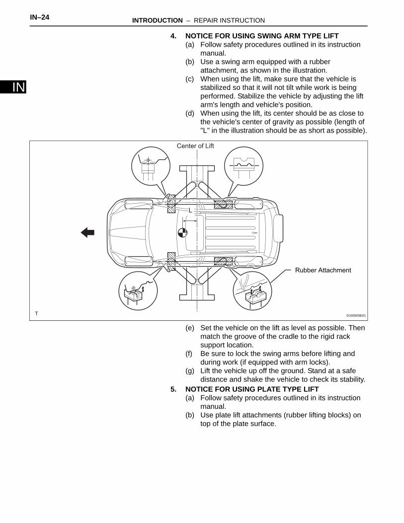
4. NOTICE FOR USING SWING ARM TYPE LIFT(a) Follow safety procedures outlined in its instruction
manual.(b) Use a swing arm equipped with a rubber
attachment, as shown in the illustration.(c) When using the lift, make sure that the vehicle is
stabilized so that it will not tilt while work is being performed. Stabilize the vehicle by adjusting the lift arm's length and vehicle's position.
(d) When using the lift, its center should be as close to the vehicle's center of gravity as possible (length of "L" in the illustration should be as short as possible).
(e) Set the vehicle on the lift as level as possible. Then match the groove of the cradle to the rigid rack support location.
(f) Be sure to lock the swing arms before lifting and during work (if equipped with arm locks).
(g) Lift the vehicle up off the ground. Stand at a safe distance and shake the vehicle to check its stability.
5. NOTICE FOR USING PLATE TYPE LIFT(a) Follow safety procedures outlined in its instruction
manual.(b) Use plate lift attachments (rubber lifting blocks) on
top of the plate surface.
Rubber Attachment
Center of Lift
L
D100925E01

INTRODUCTION – REPAIR INSTRUCTION IN–25
IN
(c) Refer to the illustration below to determine how to properly set the vehicle.
HINT:
(d) Use the lift to raise the vehicle up off the ground, and shake it to make sure that it is stable.
AttachmentA
B
Attachment Dimensions85 mm (3.35 in.)
70 mm (2.76 in.)
100 mm (3.94 in.)
200 mm (7.87 in.)
D100924E01
Right and left set position Place the vehicle over the center of the lift.
Front and rear set position Place the attachments at the ends of the rubber plate surface, under the vehicle lift pad (A and C in the illustration). Raise the plate slightly and reposition the vehicle so the top of the attachment (B in the illustration) is aligned with the front side notch in the vehicle rocker flange.

IN–26 INTRODUCTION – REPAIR INSTRUCTION
IN
CUSTOMIZE PARAMETERSNOTICE:• When the customer requests a change in a function,
first make sure that the function can be customized.• Make a note of the current settings before
customizing.• When troubleshooting a function, first make sure that
the function is set to the default setting.1. Combination meter
2. Air conditioning system
3. Power Door Lock Control System
4. Wireless Door Lock Control System
Display (Item) Default Function Setting
SEAT BELT WARN D/P ON Seat belt warning buzzer ON / OFF setting
D/P ON: Driver and passenger buzzer OND ON: Driver buzzer ONP ON: Passenger buzzer OND/P OFF: Driver and passenger buzzer OFF
Display (Item) Default Contents Setting
SET TEMP SHIFT(Set Temperature Shift) NORMAL To control with shifted temperature against
display temperature+2 C / +1 C / NORMAL / -1 C / -2 C
AIR INLET MODE(Air Inlet Mode) AUTO
In case of turning A/C ON when you desire to make compartment cool down quickly, this is function to change mode automatically to RECIRCULATION mode
MANUAL / AUTO
COMPRESSOR MODE(Compressor Mode) AUTO
Function to turn A/C ON automatically by pressing AUTO button when blower is ON and A/C is OFF
MANUAL / AUTO
COMPRS / DEF OPER(Compressor / Air Inlet DEF Operation)
LINK Function to turn A/C ON automatically linked with FRONT DEF button when A/C is OFF NORMAL / LINK
EVAP CTRL(Evaporator Control) AUTO
Function to set evaporator control to AUTOMATIC position (AUTO) to save power, or to coldest position (MANUAL) to dehumidify air and to prevent windows from fogging up
MANUAL / AUTO
FOOT / DEF MODE(Foot / DEF auto mode) ON Function to turn airflow from FOOT / DEF ON
automatically when AUTO MODE is ON OFF / ON
AUTO BLOW UP(Foot / DEF automatic blower up function)
ON Function to change blower level automatically when defroster is ON OFF / ON
Display (Item) Default Function Setting
UNLK/KEY TWICE ON Unlocks only driver side door when driver side door key cylinder turned to unlock once, and unlocks all doors when turned to unlock twice. For OFF setting, turning it once unlocks all doors.
ON / OFF
Display (Item) Default Contents Setting
HAZARD ANS BACK ON
When LOCK switch on transmitter pressed, all hazard warning lights illuminate once. When UNLOCK switch pressed, all hazard warning lights illuminate twice
ON / OFF

INTRODUCTION – REPAIR INSTRUCTION IN–27
IN
5. Lighting System
WIRLS BUZZ OPER ON
Function that makes wireless buzzer sound for answer-back when transmitter LOCK / UNLOCK switch pressed
ON / OFF
OPEN DOOR WARN ON
If door is not completely closed and transmitter LOCK switch is pressed, this function sounds a buzzer for 10 seconds
ON / OFF
WIRELESS OPER ON ON / OFF of wireless door lock function ON / OFF
ALARM FUNCTION ON
Operates security alarm when PANIC switch on transmitter continuously pressed for 1 second
ON / OFF
UNLOCK / 2 OPER ON
Function that unlocks driver side door when unlock switch on transmitter is pressed once, and unlocks all doors when pressed twice. If setting is OFF, pressing unlock switch once makes all doors unlock.
ON / OFF
AUTO LOCK DELAY 30sThis function controls amount of time from unlocking doors to automatic re-locking function
30s / 60s
Display (Item) Default Contents Setting
Display (Item) Default Contents Setting
LIGHTING TIME(Lighting Time) 15 seconds
Changes illumination duration after door closure.(It will quickly fade out in case of turning ignition switch ON.)
7.5/15/30 (seconds)
I/L ON /ACC OFF(Room light illuminates when ignition switch turned OFF)
ON
Illuminates light when ignition switch turned to ACC.(Room light illuminated when interior light switch in DOOR position)
ON / OFF
I/L ON / UNLOCK(Room light illuminates when door key unlocked.)
ON
Function to light up room light when unlocking with door key cylinder.(Room light illuminated when interior light switch in DOOR position)
ON / OFF
LIGHT CONTROL ONFunction to light up foot light when ignition switch is ON and shift position is not P.
ON / OFF
IN–28 INTRODUCTION – HOW TO TROUBLESHOOT ECU CONTROLLED SYSTEMS
IN
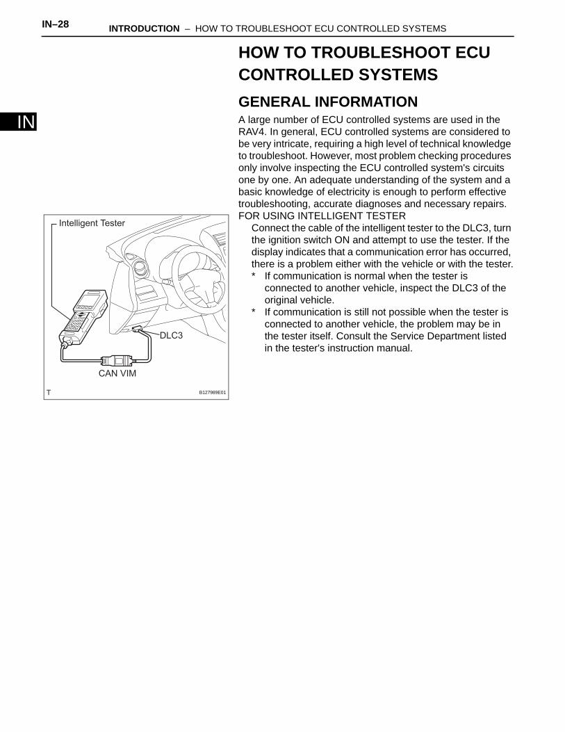
HOW TO TROUBLESHOOT ECU CONTROLLED SYSTEMSGENERAL INFORMATIONA large number of ECU controlled systems are used in the RAV4. In general, ECU controlled systems are considered to be very intricate, requiring a high level of technical knowledge to troubleshoot. However, most problem checking procedures only involve inspecting the ECU controlled system's circuits one by one. An adequate understanding of the system and a basic knowledge of electricity is enough to perform effective troubleshooting, accurate diagnoses and necessary repairs.FOR USING INTELLIGENT TESTER
Connect the cable of the intelligent tester to the DLC3, turn the ignition switch ON and attempt to use the tester. If the display indicates that a communication error has occurred, there is a problem either with the vehicle or with the tester.* If communication is normal when the tester is
connected to another vehicle, inspect the DLC3 of the original vehicle.
* If communication is still not possible when the tester is connected to another vehicle, the problem may be in the tester itself. Consult the Service Department listed in the tester's instruction manual.
Intelligent Tester
CAN VIM
DLC3
B127989E01

INTRODUCTION – HOW TO TROUBLESHOOT ECU CONTROLLED SYSTEMS IN–29
IN
HOW TO PROCEED WITH TROUBLESHOOTING1. OPERATION FLOW
HINT:Perform troubleshooting in accordance with the procedures below. The following is an outline of basic troubleshooting procedures. Confirm the troubleshooting procedures for the circuit you are working on before beginning troubleshooting.
NEXT
(a) Ask the customer about the conditions and environment when the problem occurred.
NEXT
Standard voltage:11 to 14 V
If the voltage is below 11 V, recharge or replace the battery before proceeding.
NEXT
(a) Visually check the wire harnesses, connectors and fuses for open and short circuits.
(b) Warm up the engine to the normal operating temperature.
(c) Confirm the problem symptoms and conditions, and check for DTCs.
Result
B
A
1 VEHICLE BROUGHT TO WORKSHOP
2 CUSTOMER PROBLEM ANALYSIS
3 INSPECT BATTERY VOLTAGE
4 SYMPTOM CONFIRMATION AND DTC (AND FREEZE FRAME DATA) CHECK
Result Proceed to
DTC is output A
DTC is not output B
Go to step 6

IN–30 INTRODUCTION – HOW TO TROUBLESHOOT ECU CONTROLLED SYSTEMS
IN
(a) Check the results obtained in the DTC check. Then find the output DTC in the DTC chart. Look at the "Trouble Area" column for a list of potentially malfunctioning circuits and / or parts.
NEXT
(a) Check the results obtained in the symptom confirmation. Then find the problem symptoms in the problem symptoms table. Look at the "Suspected Area" column for a list of potentially malfunctioning circuits and / or parts.
NEXT
(a) Confirm the malfunctioning circuit or part.
NEXT
(a) Adjust, repair or replace the malfunctioning circuit or parts.
NEXT
(a) After the adjustment, repairs or replacement, confirm that the malfunction no longer exists. If the malfunction does not reoccur, perform a confirmation test under the same conditions and in the same environment as when the malfunction occurred the first time.
NEXT
2. CUSTOMER PROBLEM ANALYSIS
5 DTC CHART
Go to step 7
6 PROBLEM SYMPTOMS TABLE
7 CIRCUIT INSPECTION OR PARTS INSPECTION
8 ADJUST, REPAIR OR REPLACE
9 CONFIRMATION TEST
END
INTRODUCTION – HOW TO TROUBLESHOOT ECU CONTROLLED SYSTEMS IN–31
IN
HINT:• In troubleshooting, confirm that the problem symptoms
have been accurately identified. Preconceptions should be discarded in order to make an accurate judgment. To clearly understand what the problem symptoms are, it is extremely important to ask the customer about the problem and the conditions at the time the malfunction occurred.
• Gather as much information as possible for reference. Past problems that seem unrelated may also help in some cases.
• The following 5 items are important points in the problem analysis:
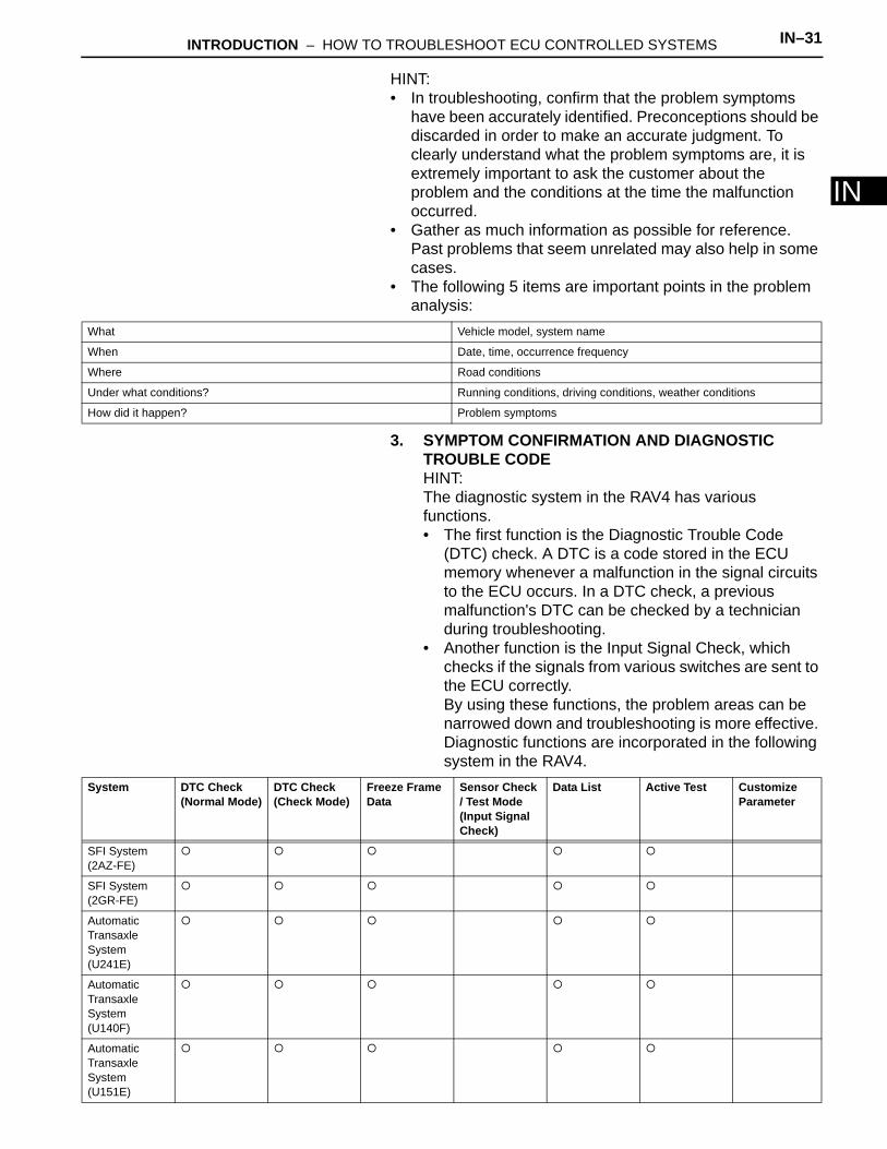
3. SYMPTOM CONFIRMATION AND DIAGNOSTIC TROUBLE CODEHINT:The diagnostic system in the RAV4 has various functions.• The first function is the Diagnostic Trouble Code
(DTC) check. A DTC is a code stored in the ECU memory whenever a malfunction in the signal circuits to the ECU occurs. In a DTC check, a previous malfunction's DTC can be checked by a technician during troubleshooting.
• Another function is the Input Signal Check, which checks if the signals from various switches are sent to the ECU correctly.By using these functions, the problem areas can be narrowed down and troubleshooting is more effective. Diagnostic functions are incorporated in the following system in the RAV4.
What Vehicle model, system name
When Date, time, occurrence frequency
Where Road conditions
Under what conditions? Running conditions, driving conditions, weather conditions
How did it happen? Problem symptoms
System DTC Check(Normal Mode)
DTC Check(Check Mode)
Freeze Frame Data
Sensor Check / Test Mode (Input Signal Check)
Data List Active Test Customize Parameter
SFI System (2AZ-FE)
SFI System (2GR-FE)
Automatic Transaxle System (U241E)
Automatic Transaxle System (U140F)
Automatic Transaxle System (U151E)

IN–32 INTRODUCTION – HOW TO TROUBLESHOOT ECU CONTROLLED SYSTEMS
IN
Automatic Transaxle System (U151F)
Active Torque Control 4WD System
Electronic Power Steering System
Vehicle Stability Control System
Tire Pressure Warning System
Meter/ Gauge System
Air Conditioning (for Automatic Air Conditioning System)
Air Conditioning (for Manual Air Conditioning System)
Airbag System
Occupant Classification System
Seat Belt Warning System
Engine Immobiliser System
Cruise Control System
Wiper and Washer System
Power Door Lock Control System
Wireless Door Lock Control System
Key Reminder Warning System
Power Window Control System
Lighting System
Sliding Roof System
System DTC Check(Normal Mode)
DTC Check(Check Mode)
Freeze Frame Data
Sensor Check / Test Mode (Input Signal Check)
Data List Active Test Customize Parameter

INTRODUCTION – HOW TO TROUBLESHOOT ECU CONTROLLED SYSTEMS IN–33
IN• In the DTC check, it is very important to determine
whether the problem indicated by the DTC is either: 1) still occurring, or 2) occurred in the past but has since returned to normal. In addition, the DTC should be compared to the problem symptom to see if they are related. For this reason, DTCs should be checked before and after confirmation of symptoms (i.e., whether or not problem symptoms exist) to determine current system conditions, as shown in the flowchart below.
• Never skip the DTC check. Failing to check DTCs may, depending on the case, result in unnecessary troubleshooting for systems operating normally or lead to repairs not related to the problem. Follow the procedures listed in the flowchart in the correct order.
• The following flowchart shows how to proceed with troubleshooting using the DTC check. Directions from the flowchart will indicate how to proceed either to DTC troubleshooting or to the troubleshooting of each problem symptom.
NEXT
NEXT
Result
B
A
Audio and Visual System
CAN Communication System
System DTC Check(Normal Mode)
DTC Check(Check Mode)
Freeze Frame Data
Sensor Check / Test Mode (Input Signal Check)
Data List Active Test Customize Parameter
1 DTC CHECK
2 MAKE A NOTE OF DTCS DISPLAYED AND THEN CLEAR MEMORY
3 SYMPTOM CONFIRMATION
Result Proceed to
No symptoms exist A
Symptoms exist B
Go to step 5

IN–34 INTRODUCTION – HOW TO TROUBLESHOOT ECU CONTROLLED SYSTEMS
INNEXT
Result
B
A
Result
If a DTC was displayed in the initial DTC check, the problem may have occurred in a wire harness or connector in that circuit in the past. Check the wire harness and connectors.
B
A
The problem is still occurring in a place other than the diagnostic circuit (the DTC displayed first is either for a past problem or a secondary problem).4. SYMPTOM SIMULATION
HINT:The most difficult case in troubleshooting is when no problem symptoms occur. In such a case, a thorough problem analysis must be carried out. A simulation of the same or similar conditions and environment in which the problem occurred in the customer's vehicle should be carried out. No matter how much skill or experience a technician has, troubleshooting without confirming the problem symptoms will lead to important repairs being overlooked and mistakes or delays.
4 SIMULATION TEST USING SYMPTOM SIMULATION METHODS
5 DTC CHECK
Result Proceed to
DTC is not output A
DTC is output B
TROUBLESHOOTING OF PROBLEM INDICATED BY DTC
6 SYMPTOM CONFIRMATION
Result Proceed to
Symptoms exist A
No symptoms exist B
SYSTEM NORMAL
TROUBLESHOOTING OF EACH PROBLEM SYMPTOM
INTRODUCTION – HOW TO TROUBLESHOOT ECU CONTROLLED SYSTEMS IN–35
IN
For example:With a problem that only occurs when the engine is cold or as a result of vibration caused by the road during driving, the problem can never be determined if the symptoms are being checked on a stationary vehicle or on a vehicle with a warmed-up engine. Vibration, heat or water penetration (moisture) is difficult to reproduce. The symptom simulation tests below are effective substitutes for the conditions and can be applied on a stationary vehicle.Important points in the symptom simulation test:In the symptom simulation test, the problem symptoms as well as the problem area or parts must be confirmed. First, narrow down the possible problem circuits according to the symptoms. Then, connect the tester and carry out the symptom simulation test, judging whether the circuit being tested is defective or normal. Also, confirm the problem symptoms at the same time. Refer to the problem symptoms table for each system to narrow down the possible causes.
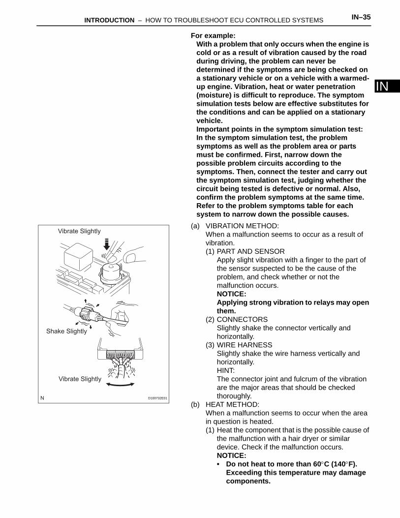
(a) VIBRATION METHOD:When a malfunction seems to occur as a result of vibration.(1) PART AND SENSOR
Apply slight vibration with a finger to the part of the sensor suspected to be the cause of the problem, and check whether or not the malfunction occurs.NOTICE:Applying strong vibration to relays may open them.
(2) CONNECTORSSlightly shake the connector vertically and horizontally.
(3) WIRE HARNESSSlightly shake the wire harness vertically and horizontally. HINT:The connector joint and fulcrum of the vibration are the major areas that should be checked thoroughly.
(b) HEAT METHOD:When a malfunction seems to occur when the area in question is heated.(1) Heat the component that is the possible cause of
the malfunction with a hair dryer or similar device. Check if the malfunction occurs.NOTICE:• Do not heat to more than 60°C (140°F).
Exceeding this temperature may damage components.
Vibrate Slightly
Shake Slightly
Vibrate Slightly
D100732E01
IN–36 INTRODUCTION – HOW TO TROUBLESHOOT ECU CONTROLLED SYSTEMS
IN
• Do not apply heat directly to the parts in the ECU.
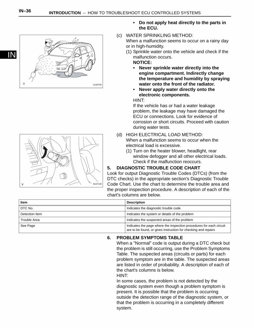
(c) WATER SPRINKLING METHOD:When a malfunction seems to occur on a rainy day or in high-humidity.(1) Sprinkle water onto the vehicle and check if the
malfunction occurs.NOTICE:• Never sprinkle water directly into the
engine compartment. Indirectly change the temperature and humidity by spraying water onto the front of the radiator.
• Never apply water directly onto the electronic components.
HINT:If the vehicle has or had a water leakage problem, the leakage may have damaged the ECU or connections. Look for evidence of corrosion or short circuits. Proceed with caution during water tests.
(d) HIGH ELECTRICAL LOAD METHOD:When a malfunction seems to occur when the electrical load is excessive.(1) Turn on the heater blower, headlight, rear
window defogger and all other electrical loads. Check if the malfunction reoccurs.
5. DIAGNOSTIC TROUBLE CODE CHARTLook for output Diagnostic Trouble Codes (DTCs) (from the DTC checks) in the appropriate section's Diagnostic Trouble Code Chart. Use the chart to determine the trouble area and the proper inspection procedure. A description of each of the chart's columns are below.
6. PROBLEM SYMPTOMS TABLEWhen a "Normal" code is output during a DTC check but the problem is still occurring, use the Problem Symptoms Table. The suspected areas (circuits or parts) for each problem symptom are in the table. The suspected areas are listed in order of probability. A description of each of the chart's columns is below.HINT:In some cases, the problem is not detected by the diagnostic system even though a problem symptom is present. It is possible that the problem is occurring outside the detection range of the diagnostic system, or that the problem is occurring in a completely different system.
D100705
AUTO
B107149
Item Description
DTC No. Indicates the diagnostic trouble code
Detection Item Indicates the system or details of the problem
Trouble Area Indicates the suspected areas of the problem
See Page Indicates the page where the inspection procedures for each circuit are to be found, or gives instruction for checking and repairs

INTRODUCTION – HOW TO TROUBLESHOOT ECU CONTROLLED SYSTEMS IN–37
IN7. CIRCUIT INSPECTION
A description of the main areas of each circuit inspection is below.
Item Description
Symptom -
Suspected Area Indicates the circuit or part which needs to be checked.
See Page Indicates the page where the flowchart for each circuit is located.
Item Description
Description The major role, operation of the circuit and its component parts are explained.
DTC No., DTC Detection Condition, Trouble Area Indicates the diagnostic trouble codes, diagnostic trouble code detection conditions, and trouble areas of a problem.
Wiring Diagram This shows a wiring diagram of the circuit.Use this diagram together with ELECTRICAL WIRING DIAGRAM to thoroughly understand the circuit.
Inspection Procedures Use the inspection procedures to determine if the circuit is normal or abnormal. If abnormal, use the inspection procedures to determine whether the problem is located in the sensors, actuators, wire harnesses or ECU.
Inspection Procedure Connector Illustrations • Connector being checked is connected:Connections of tester are indicated by (+) or (-) after the terminal name.
• Connector being checked is disconnected:For illustrations of inspections between a connector and body ground, information about the body ground is not shown in the illustration.
IN–38 INTRODUCTION – HOW TO TROUBLESHOOT ECU CONTROLLED SYSTEMS
IN
ELECTRONIC CIRCUIT INSPECTION PROCEDURE1. BASIC INSPECTION
(a) WHEN MEASURING RESISTANCE OF ELECTRONIC PARTS(1) Unless otherwise stated, all resistance
measurements should be made at an ambient temperature of 20°C (68°F). Resistance measurements may be inaccurate if measured at high temperatures, i.e. immediately after the vehicle has been running. Measurements should be made after the engine has cooled down.
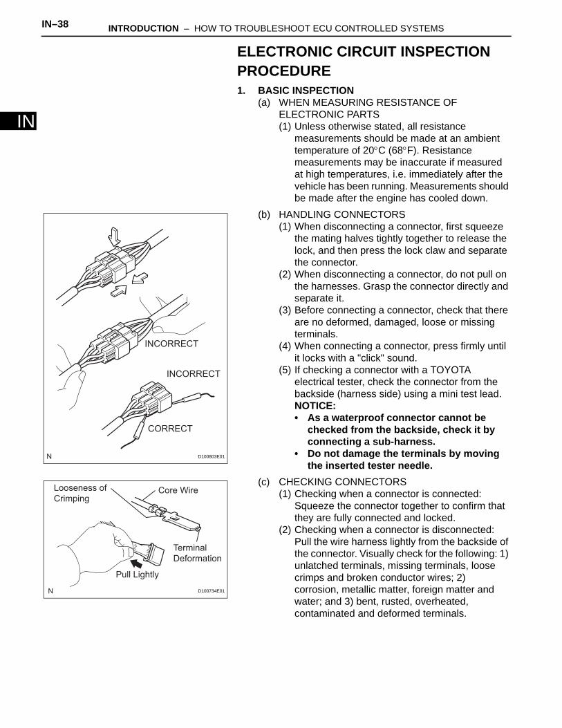
(b) HANDLING CONNECTORS(1) When disconnecting a connector, first squeeze
the mating halves tightly together to release the lock, and then press the lock claw and separate the connector.
(2) When disconnecting a connector, do not pull on the harnesses. Grasp the connector directly and separate it.
(3) Before connecting a connector, check that there are no deformed, damaged, loose or missing terminals.
(4) When connecting a connector, press firmly until it locks with a "click" sound.
(5) If checking a connector with a TOYOTA electrical tester, check the connector from the backside (harness side) using a mini test lead.NOTICE:• As a waterproof connector cannot be
checked from the backside, check it by connecting a sub-harness.
• Do not damage the terminals by moving the inserted tester needle.
(c) CHECKING CONNECTORS(1) Checking when a connector is connected:
Squeeze the connector together to confirm that they are fully connected and locked.
(2) Checking when a connector is disconnected:Pull the wire harness lightly from the backside of the connector. Visually check for the following: 1) unlatched terminals, missing terminals, loose crimps and broken conductor wires; 2) corrosion, metallic matter, foreign matter and water; and 3) bent, rusted, overheated, contaminated and deformed terminals.
INCORRECT
INCORRECT
CORRECT
D100803E01
Core Wire
Terminal
Deformation
Pull Lightly
Looseness of
Crimping
D100734E01

INTRODUCTION – HOW TO TROUBLESHOOT ECU CONTROLLED SYSTEMS IN–39
IN
(3) Checking the contact pressure of the terminal:Prepare a spare male terminal. Insert it into a female terminal, and check for ample tension when inserting and after full engagement.NOTICE:When testing a gold-plated female terminal, always use a gold-plated male terminal.
(d) REPAIR METHOD OF CONNECTOR TERMINAL(1) If there is any foreign matter on the terminal,
clean the contact point using an air gun or cloth. Never rub the contact point using sandpaper as the plating may come off.
(2) If there is abnormal contact pressure, replace the female terminal. If the male terminal is gold-plated (gold color), use a gold-plated female terminal; if it is silver-plated (silver color), use a silver-plated female terminal.
(3) Damaged, deformed, or corroded terminals should be replaced. If the terminal does not lock into the housing, the housing may have to be replaced.
(e) HANDLING OF WIRE HARNESS(1) If removing a wire harness, check the wiring and
clamping before proceeding so that it can be restored in the same way.
(2) Never twist, pull or slacken the wire harness more than necessary.
(3) The wire harness should never come into contact with a high temperature part, or rotating, moving, vibrating or sharp-edged parts. Avoid contact with panel edges, screw tips and other sharp items.
(4) When installing parts, never pinch the wire harness.
(5) Never cut or break the cover of the wire harness. If it is cut or broken, repair the cover with vinyl tape or replace the wire harness.
2. CHECK FOR OPEN CIRCUIT(a) For an open circuit in the wire harness in Fig. 1,
check the resistance or voltage, as described below.
D100735
INCORRECTCORRECT
D100736E01
INCORRECT INCORRECT
INCORRECTD100784E01
Fig. 1
OPENC B A
ECU
SENSOR
1
2
1
2
1
2
1
2
D100785E01
IN–40 INTRODUCTION – HOW TO TROUBLESHOOT ECU CONTROLLED SYSTEMS
IN
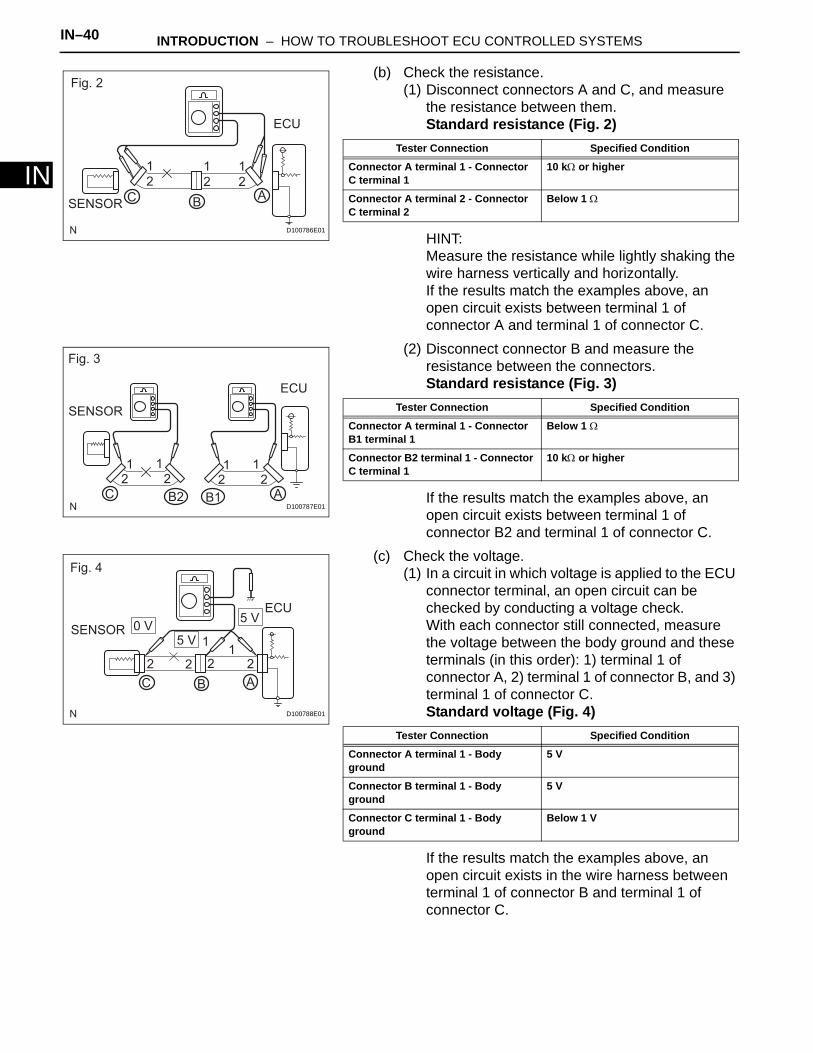
(b) Check the resistance.(1) Disconnect connectors A and C, and measure
the resistance between them.Standard resistance (Fig. 2)
HINT:Measure the resistance while lightly shaking the wire harness vertically and horizontally.If the results match the examples above, an open circuit exists between terminal 1 of connector A and terminal 1 of connector C.
(2) Disconnect connector B and measure the resistance between the connectors.Standard resistance (Fig. 3)
If the results match the examples above, an open circuit exists between terminal 1 of connector B2 and terminal 1 of connector C.
(c) Check the voltage.(1) In a circuit in which voltage is applied to the ECU
connector terminal, an open circuit can be checked by conducting a voltage check.With each connector still connected, measure the voltage between the body ground and these terminals (in this order): 1) terminal 1 of connector A, 2) terminal 1 of connector B, and 3) terminal 1 of connector C.Standard voltage (Fig. 4)
If the results match the examples above, an open circuit exists in the wire harness between terminal 1 of connector B and terminal 1 of connector C.
Fig. 2
ECU
1
2
1
2
1
2
SENSORC B
A
D100786E01
Tester Connection Specified Condition
Connector A terminal 1 - Connector C terminal 1
10 kΩ or higher
Connector A terminal 2 - Connector C terminal 2
Below 1 Ω
Fig. 3
SENSOR
ECU
C
1 1
2 21 1
2 2
B2 B1 AD100787E01
Tester Connection Specified Condition
Connector A terminal 1 - Connector B1 terminal 1
Below 1 Ω
Connector B2 terminal 1 - Connector C terminal 1
10 kΩ or higher
Fig. 4
ECU5 V
5 V0 VSENSOR
11
2 2 2 2
C AB
D100788E01
Tester Connection Specified Condition
Connector A terminal 1 - Body ground
5 V
Connector B terminal 1 - Body ground
5 V
Connector C terminal 1 - Body ground
Below 1 V

INTRODUCTION – HOW TO TROUBLESHOOT ECU CONTROLLED SYSTEMS IN–41
IN
3. CHECK FOR SHORT CIRCUIT(a) If the wire harness is ground shorted (Fig. 5), locate
the section by conducting a resistance check with the body ground (below).
(b) Check the resistance with the body ground.(1) Disconnect connectors A and C, and measure
the resistance.Standard resistance (Fig. 6)
HINT:Measure the resistance while lightly shaking the wire harness vertically and horizontally.If the results match the examples above, a short circuit exists between terminal 1 of connector A and terminal 1 of connector C.
(2) Disconnect connector B and measure the resistance.Standard resistance (Fig. 7)
If the results match the examples above, a short circuit exists between terminal 1 of connector B2 and terminal 1 of connector C.
4. CHECK AND REPLACE ECUNOTICE:• The connector should not be disconnected from
the ECU. Perform the inspection from the backside of the connector on the wire harness side.
• When no measuring condition is specified, perform the inspection with the engine stopped and the ignition switch ON.
• Check that the connectors are fully seated. Check for loose, corroded or broken wires.
Fig. 5
SHORTECU
C B A
1
2
1
2
1
2
D100789E01
Fig. 6
SENSOR
ECU
CB
A
1 1 12 2 2
D100790E01
Tester Connection Specified Condition
Connector A terminal 1 - Body ground
Below 1 Ω
Connector A terminal 2 - Body ground
10 kΩ or higher
Fig. 7
SENSOR
ECU
1 12 2
1 12 2
C AB1B2
D100800E01
Tester Connection Specified Condition
Connector A terminal 1 - Body ground
10 kΩ or higher
Connector B2 terminal 1 - Body ground
Below 1 Ω
IN–42 INTRODUCTION – HOW TO TROUBLESHOOT ECU CONTROLLED SYSTEMS
IN
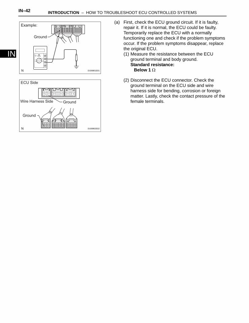
(a) First, check the ECU ground circuit. If it is faulty, repair it. If it is normal, the ECU could be faulty. Temporarily replace the ECU with a normally functioning one and check if the problem symptoms occur. If the problem symptoms disappear, replace the original ECU.(1) Measure the resistance between the ECU
ground terminal and body ground.Standard resistance:
Below 1 Ω
(2) Disconnect the ECU connector. Check the ground terminal on the ECU side and wire harness side for bending, corrosion or foreign matter. Lastly, check the contact pressure of the female terminals.
Example:
Ground
D100801E01
ECU Side
Wire Harness Side Ground
Ground
D100802E02
IN–42 INTRODUCTION – TERMS
IN
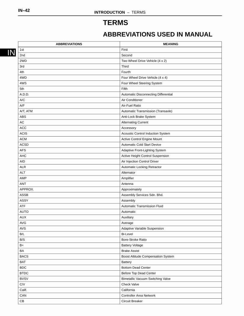
TERMSABBREVIATIONS USED IN MANUAL
ABBREVIATIONS MEANING
1st First
2nd Second
2WD Two Wheel Drive Vehicle (4 x 2)
3rd Third
4th Fourth
4WD Four Wheel Drive Vehicle (4 x 4)
4WS Four Wheel Steering System
5th Fifth
A.D.D. Automatic Disconnecting Differential
A/C Air Conditioner
A/F Air-Fuel Ratio
A/T, ATM Automatic Transmission (Transaxle)
ABS Anti-Lock Brake System
AC Alternating Current
ACC Accessory
ACIS Acoustic Control Induction System
ACM Active Control Engine Mount
ACSD Automatic Cold Start Device
AFS Adaptive Front-Lighting System
AHC Active Height Control Suspension
AID Air Injection Control Driver
ALR Automatic Locking Retractor
ALT Alternator
AMP Amplifier
ANT Antenna
APPROX. Approximately
ASSB Assembly Services Sdn. Bhd.
ASSY Assembly
ATF Automatic Transmission Fluid
AUTO Automatic
AUX Auxiliary
AVG Average
AVS Adaptive Variable Suspension
B/L Bi-Level
B/S Bore-Stroke Ratio
B+ Battery Voltage
BA Brake Assist
BACS Boost Altitude Compensation System
BAT Battery
BDC Bottom Dead Center
BTDC Before Top Dead Center
BVSV Bimetallic Vacuum Switching Valve
C/V Check Valve
Calif. California
CAN Controller Area Network
CB Circuit Breaker
INTRODUCTION – TERMS IN–43
IN
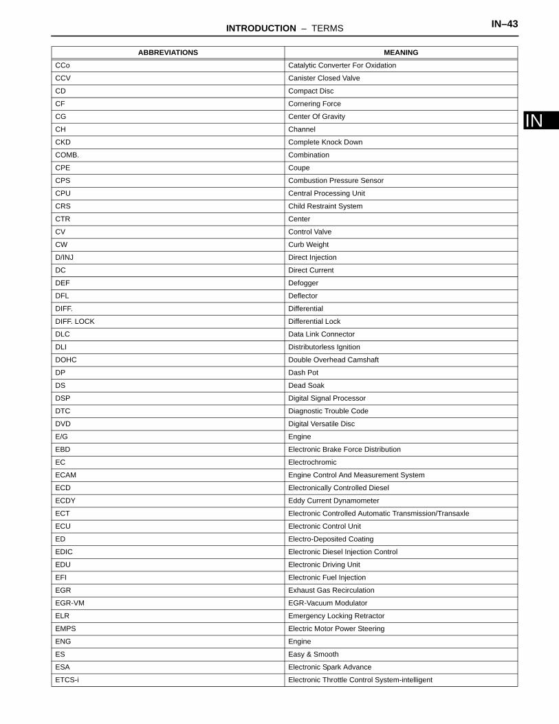
CCo Catalytic Converter For Oxidation
CCV Canister Closed Valve
CD Compact Disc
CF Cornering Force
CG Center Of Gravity
CH Channel
CKD Complete Knock Down
COMB. Combination
CPE Coupe
CPS Combustion Pressure Sensor
CPU Central Processing Unit
CRS Child Restraint System
CTR Center
CV Control Valve
CW Curb Weight
D/INJ Direct Injection
DC Direct Current
DEF Defogger
DFL Deflector
DIFF. Differential
DIFF. LOCK Differential Lock
DLC Data Link Connector
DLI Distributorless Ignition
DOHC Double Overhead Camshaft
DP Dash Pot
DS Dead Soak
DSP Digital Signal Processor
DTC Diagnostic Trouble Code
DVD Digital Versatile Disc
E/G Engine
EBD Electronic Brake Force Distribution
EC Electrochromic
ECAM Engine Control And Measurement System
ECD Electronically Controlled Diesel
ECDY Eddy Current Dynamometer
ECT Electronic Controlled Automatic Transmission/Transaxle
ECU Electronic Control Unit
ED Electro-Deposited Coating
EDIC Electronic Diesel Injection Control
EDU Electronic Driving Unit
EFI Electronic Fuel Injection
EGR Exhaust Gas Recirculation
EGR-VM EGR-Vacuum Modulator
ELR Emergency Locking Retractor
EMPS Electric Motor Power Steering
ENG Engine
ES Easy & Smooth
ESA Electronic Spark Advance
ETCS-i Electronic Throttle Control System-intelligent
ABBREVIATIONS MEANING
IN–44 INTRODUCTION – TERMS
IN
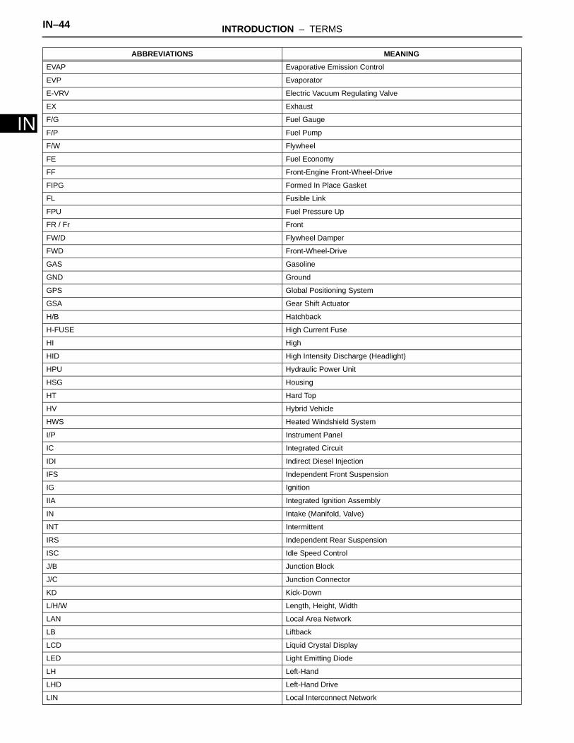
EVAP Evaporative Emission Control
EVP Evaporator
E-VRV Electric Vacuum Regulating Valve
EX Exhaust
F/G Fuel Gauge
F/P Fuel Pump
F/W Flywheel
FE Fuel Economy
FF Front-Engine Front-Wheel-Drive
FIPG Formed In Place Gasket
FL Fusible Link
FPU Fuel Pressure Up
FR / Fr Front
FW/D Flywheel Damper
FWD Front-Wheel-Drive
GAS Gasoline
GND Ground
GPS Global Positioning System
GSA Gear Shift Actuator
H/B Hatchback
H-FUSE High Current Fuse
HI High
HID High Intensity Discharge (Headlight)
HPU Hydraulic Power Unit
HSG Housing
HT Hard Top
HV Hybrid Vehicle
HWS Heated Windshield System
I/P Instrument Panel
IC Integrated Circuit
IDI Indirect Diesel Injection
IFS Independent Front Suspension
IG Ignition
IIA Integrated Ignition Assembly
IN Intake (Manifold, Valve)
INT Intermittent
IRS Independent Rear Suspension
ISC Idle Speed Control
J/B Junction Block
J/C Junction Connector
KD Kick-Down
L/H/W Length, Height, Width
LAN Local Area Network
LB Liftback
LCD Liquid Crystal Display
LED Light Emitting Diode
LH Left-Hand
LHD Left-Hand Drive
LIN Local Interconnect Network
ABBREVIATIONS MEANING

INTRODUCTION – TERMS IN–45
IN
LLC Long-Life Coolant
LNG Liquefied Natural Gas
LO Low
LPG Liquefied Petroleum Gas
LSD Limited Slip Differential
LSP & BV Load Sensing Proportioning and Bypass Valve
LSPV Load Sensing Proportioning Valve
M/T, MTM Manual Transmission (Transaxle)
MAP Manifold Absolute Pressure
MAX. Maximum
MG1 Motor Generator No. 1
MG2 Motor Generator No. 2
MIC Microphone
MIL Malfunction Indicator Lamp
MIN. Minimum
MMT Multi-mode Manual Transmission
MP Multipurpose
MPI Multipoint Electronic Injection
MPX Multiplex Communication System
MT Mount
MTG Mounting
N Neutral
NA Natural Aspiration
NO. / No. Number
O/D Overdrive
O/S Oversize
O2S Oxygen Sensor
OC Oxidation Catalyst
OCV Oil Control Valve
OEM Original Equipment Manufacturing
OHC Overhead Camshaft
OHV Overhead Valve
OPT Option
ORVR On-board Refueling Vapor Recovery
P & BV Proportioning And Bypass Valve
P/W Power Window
PBD Power Back Door
PCS Power Control System
PCV Positive Crankcase Ventilation
PKB Parking Brake
PPS Progressive Power Steering
PROM Programmable Read Only Memory
PS Power Steering
PSD Power Slide Door
PTC Positive Temperature Coefficient
PTO Power Take-Off
PZEV Partial Zero Emission Vehicle
R & P Rack and Pinion
R/B Relay Block
ABBREVIATIONS MEANING

IN–46 INTRODUCTION – TERMS
IN
R/F Reinforcement
RAM Random Access Memory
RBS Recirculating Ball Type Steering
RFS Rigid Front Suspension
RH Right-Hand
RHD Right-Hand Drive
RLY Relay
ROM Read Only Memory
RR / Rr Rear
RRS Rigid Rear Suspension
RSE Rear Seat Entertainment
RWD Rear-Wheel Drive
SC Supercharger
SCV Swirl Control Valve
SDN Sedan
SEN Sensor
SICS Starting Injection Control System
SOC State Of Charge
SOHC Single Overhead Camshaft
SPEC Specification
SPI Single Point Injection
SRS Supplemental Restraint System
SSM Special Service Materials
SST Special Service Tools
STD Standard
STJ Cold-Start Fuel Injection
SW Switch
SYS System
T/A Transaxle
T/M Transmission
TACH Tachometer
TAM P.T. TOYOTA-Astra Motor
TASA TOYOTA Argentina S.A.
TAT TOYOTA Motor Thailand Co. Ltd.
TAW TOYOTA Auto Works Co. Ltd.
TBI Throttle Body Electronic Fuel Injection
TC Turbocharger
TCCS TOYOTA Computer-Controlled System
TCV Timing Control Valve
TDC Top Dead Center
TDV TOYOTA de Venezuela C.A.
TEMP. Temperature
TEMS TOYOTA Electronic Modulated Suspension
TFT TOYOTA Free-Tronic
TIS Total Information System For Vehicle Development
TKM TOYOTA Kirloskar Motor Ltd.
TMC TOYOTA Motor Corporation
TMMIN P.T. TOYOTA Motor Manufacturing Indonesia
TMMK TOYOTA Motor Manufacturing Kentucky, Inc.
ABBREVIATIONS MEANING

INTRODUCTION – TERMS IN–47
IN
TMP TOYOTA Motor Philippines Corp.
TMT TOYOTA Motor Thailand Co. Ltd.
TRAC Traction Control System
TRC Traction Control System
TSAM TOYOTA South Africa Motors (Pty) Ltd.
TURBO Turbocharge
TWC Three-Way Catalyst
U/D Underdrive
U/S Undersize
VCV Vacuum Control Valve
VDIM Vehicle Dynamics Integrated Management
VENT Ventilator
VGRS Variable Gear Ratio Steering
VIM Vehicle Interface Module
VIN Vehicle Identification Number
VPS Variable Power Steering
VSC Vehicle Stability Control
VSV Vacuum Switching Valve
VTV Vacuum Transmitting Valve
VVT-i Variable Valve Timing-intelligent
W/ / w/ With
W/H Wire Harness
W/O / w/o Without
WGN Wagon
ABBREVIATIONS MEANING
IN–48 INTRODUCTION – TERMS
IN
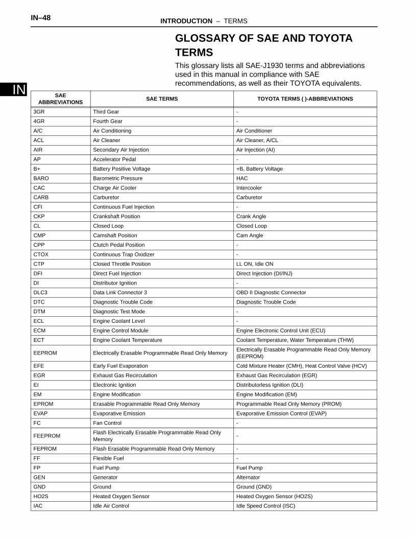
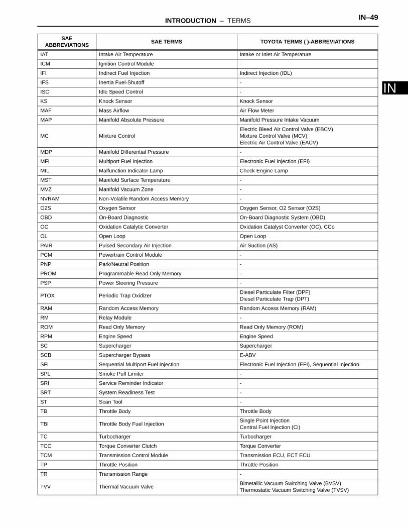
GLOSSARY OF SAE AND TOYOTA TERMSThis glossary lists all SAE-J1930 terms and abbreviations used in this manual in compliance with SAE recommendations, as well as their TOYOTA equivalents.
SAE ABBREVIATIONS SAE TERMS TOYOTA TERMS ( )-ABBREVIATIONS
3GR Third Gear -
4GR Fourth Gear -
A/C Air Conditioning Air Conditioner
ACL Air Cleaner Air Cleaner, A/CL
AIR Secondary Air Injection Air Injection (AI)
AP Accelerator Pedal -
B+ Battery Positive Voltage +B, Battery Voltage
BARO Barometric Pressure HAC
CAC Charge Air Cooler Intercooler
CARB Carburetor Carburetor
CFI Continuous Fuel Injection -
CKP Crankshaft Position Crank Angle
CL Closed Loop Closed Loop
CMP Camshaft Position Cam Angle
CPP Clutch Pedal Position -
CTOX Continuous Trap Oxidizer -
CTP Closed Throttle Position LL ON, Idle ON
DFI Direct Fuel Injection Direct Injection (DI/INJ)
DI Distributor Ignition -
DLC3 Data Link Connector 3 OBD II Diagnostic Connector
DTC Diagnostic Trouble Code Diagnostic Trouble Code
DTM Diagnostic Test Mode -
ECL Engine Coolant Level -
ECM Engine Control Module Engine Electronic Control Unit (ECU)
ECT Engine Coolant Temperature Coolant Temperature, Water Temperature (THW)
EEPROM Electrically Erasable Programmable Read Only Memory Electrically Erasable Programmable Read Only Memory (EEPROM)
EFE Early Fuel Evaporation Cold Mixture Heater (CMH), Heat Control Valve (HCV)
EGR Exhaust Gas Recirculation Exhaust Gas Recirculation (EGR)
EI Electronic Ignition Distributorless Ignition (DLI)
EM Engine Modification Engine Modification (EM)
EPROM Erasable Programmable Read Only Memory Programmable Read Only Memory (PROM)
EVAP Evaporative Emission Evaporative Emission Control (EVAP)
FC Fan Control -
FEEPROM Flash Electrically Erasable Programmable Read Only Memory -
FEPROM Flash Erasable Programmable Read Only Memory -
FF Flexible Fuel -
FP Fuel Pump Fuel Pump
GEN Generator Alternator
GND Ground Ground (GND)
HO2S Heated Oxygen Sensor Heated Oxygen Sensor (HO2S)
IAC Idle Air Control Idle Speed Control (ISC)
INTRODUCTION – TERMS IN–49
IN
IAT Intake Air Temperature Intake or Inlet Air Temperature
ICM Ignition Control Module -
IFI Indirect Fuel Injection Indirect Injection (IDL)
IFS Inertia Fuel-Shutoff -
ISC Idle Speed Control -
KS Knock Sensor Knock Sensor
MAF Mass Airflow Air Flow Meter
MAP Manifold Absolute Pressure Manifold Pressure Intake Vacuum
MC Mixture ControlElectric Bleed Air Control Valve (EBCV) Mixture Control Valve (MCV) Electric Air Control Valve (EACV)
MDP Manifold Differential Pressure -
MFI Multiport Fuel Injection Electronic Fuel Injection (EFI)
MIL Malfunction Indicator Lamp Check Engine Lamp
MST Manifold Surface Temperature -
MVZ Manifold Vacuum Zone -
NVRAM Non-Volatile Random Access Memory -
O2S Oxygen Sensor Oxygen Sensor, O2 Sensor (O2S)
OBD On-Board Diagnostic On-Board Diagnostic System (OBD)
OC Oxidation Catalytic Converter Oxidation Catalyst Converter (OC), CCo
OL Open Loop Open Loop
PAIR Pulsed Secondary Air Injection Air Suction (AS)
PCM Powertrain Control Module -
PNP Park/Neutral Position -
PROM Programmable Read Only Memory -
PSP Power Steering Pressure -
PTOX Periodic Trap Oxidizer Diesel Particulate Filter (DPF) Diesel Particulate Trap (DPT)
RAM Random Access Memory Random Access Memory (RAM)
RM Relay Module -
ROM Read Only Memory Read Only Memory (ROM)
RPM Engine Speed Engine Speed
SC Supercharger Supercharger
SCB Supercharger Bypass E-ABV
SFI Sequential Multiport Fuel Injection Electronic Fuel Injection (EFI), Sequential Injection
SPL Smoke Puff Limiter -
SRI Service Reminder Indicator -
SRT System Readiness Test -
ST Scan Tool -
TB Throttle Body Throttle Body
TBI Throttle Body Fuel Injection Single Point Injection Central Fuel Injection (Ci)
TC Turbocharger Turbocharger
TCC Torque Converter Clutch Torque Converter
TCM Transmission Control Module Transmission ECU, ECT ECU
TP Throttle Position Throttle Position
TR Transmission Range -
TVV Thermal Vacuum Valve Bimetallic Vacuum Switching Valve (BVSV) Thermostatic Vacuum Switching Valve (TVSV)
SAE ABBREVIATIONS SAE TERMS TOYOTA TERMS ( )-ABBREVIATIONS
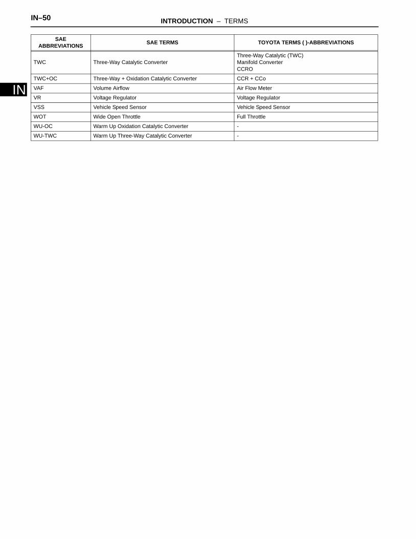
IN–50 INTRODUCTION – TERMS
IN
TWC Three-Way Catalytic ConverterThree-Way Catalytic (TWC) Manifold ConverterCCRO
TWC+OC Three-Way + Oxidation Catalytic Converter CCR + CCo
VAF Volume Airflow Air Flow Meter
VR Voltage Regulator Voltage Regulator
VSS Vehicle Speed Sensor Vehicle Speed Sensor
WOT Wide Open Throttle Full Throttle
WU-OC Warm Up Oxidation Catalytic Converter -
WU-TWC Warm Up Three-Way Catalytic Converter -
SAE ABBREVIATIONS SAE TERMS TOYOTA TERMS ( )-ABBREVIATIONS