Spec Sheet MD1230/MP1590 - elsinco · model mu120120a mu120119a mu120103a mu120104a mu120105a...
28
MD1230/MP1590 Family IP/Ethernet Spec Sheet MD1230B Data Quality Analyzer MD1231A1 IP Network Analyzer MP1590B/MP1591A Network Performance Tester Specifications
Transcript of Spec Sheet MD1230/MP1590 - elsinco · model mu120120a mu120119a mu120103a mu120104a mu120105a...

MD1230/MP1590 FamilyIP/Ethernet
Spec Sheet
MD1230B Data Quality Analyzer
MD1231A1 IP Network Analyzer
MP1590B/MP1591A Network Performance Tester
Specifications
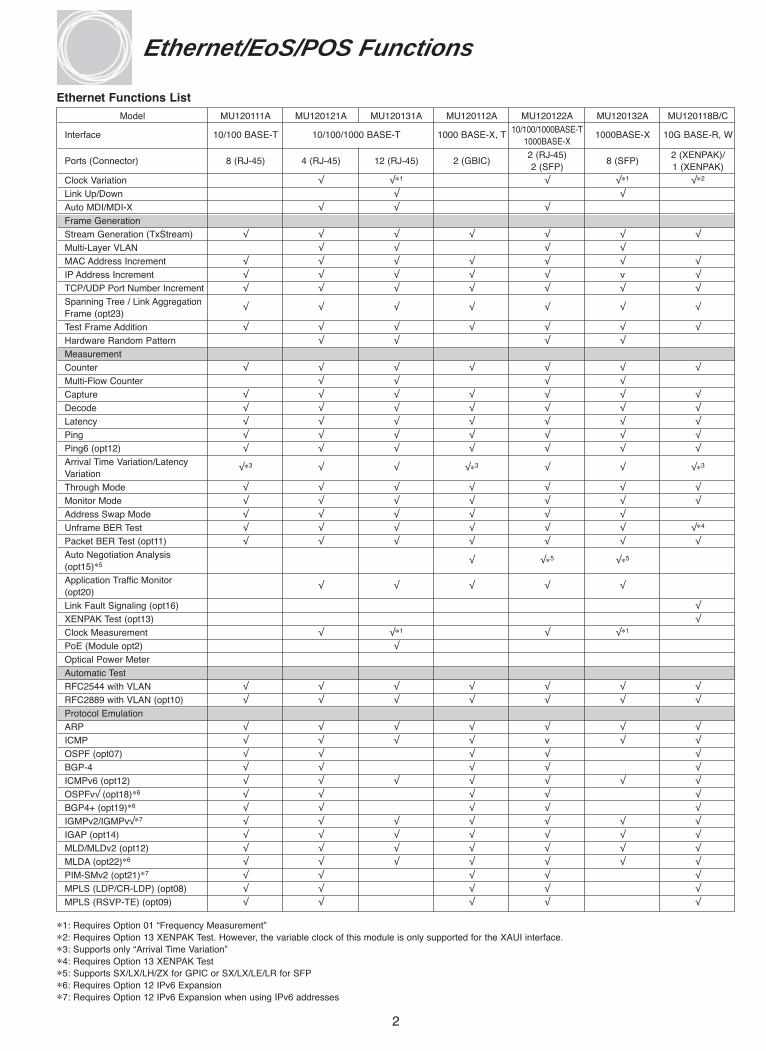
Model MU120111A MU120121A MU120131A MU120112A MU120122A MU120132A MU120118B/C
Interface 10/100 BASE-T 10/100/1000 BASE-T 1000 BASE-X, T 10/100/1000BASE-T 1000BASE-X 10G BASE-R, W1000BASE-X
Ports (Connector) 8 (RJ-45) 4 (RJ-45) 12 (RJ-45) 2 (GBIC)2 (RJ-45)
8 (SFP)2 (XENPAK)/
2 (SFP) 1 (XENPAK)
Clock Variation √ √∗1 √ √∗1 √∗2
Link Up/Down √ √
Auto MDI/MDI-X √ √ √
Frame Generation
Stream Generation (TxStream) √ √ √ √ √ √ √
Multi-Layer VLAN √ √ √ √
MAC Address Increment √ √ √ √ √ √ √
IP Address Increment √ √ √ √ √ v √
TCP/UDP Port Number Increment √ √ √ √ √ √ √
Spanning Tree / Link Aggregation Frame (opt23)
√ √ √ √ √ √ √
Test Frame Addition √ √ √ √ √ √ √
Hardware Random Pattern √ √ √ √
Measurement
Counter √ √ √ √ √ √ √
Multi-Flow Counter √ √ √ √
Capture √ √ √ √ √ √ √
Decode √ √ √ √ √ √ √
Latency √ √ √ √ √ √ √
Ping √ √ √ √ √ √ √
Ping6 (opt12) √ √ √ √ √ √ √
Arrival Time Variation/Latency Variation
√∗3 √ √ √∗3 √ √ √∗3
Through Mode √ √ √ √ √ √ √
Monitor Mode √ √ √ √ √ √ √
Address Swap Mode √ √ √ √ √ √
Unframe BER Test √ √ √ √ √ √ √∗4
Packet BER Test (opt11) √ √ √ √ √ √ √
Auto Negotiation Analysis (opt15)∗5
√ √∗5 √∗5
Application Traffic Monitor (opt20)
√ √ √ √ √
Link Fault Signaling (opt16) √
XENPAK Test (opt13) √
Clock Measurement √ √∗1 √ √∗1
PoE (Module opt2) √
Optical Power Meter
Automatic Test
RFC2544 with VLAN √ √ √ √ √ √ √
RFC2889 with VLAN (opt10) √ √ √ √ √ √ √
Protocol Emulation
ARP √ √ √ √ √ √ √
ICMP √ √ √ √ v √ √
OSPF (opt07) √ √ √ √ √
BGP-4 √ √ √ √ √
ICMPv6 (opt12) √ √ √ √ √ √ √
OSPFv√ (opt18)∗6 √ √ √ √ √
BGP4+ (opt19)∗6 √ √ √ √ √
IGMPv2/IGMPv√∗7 √ √ √ √ √ √ √
IGAP (opt14) √ √ √ √ √ √ √
MLD/MLDv2 (opt12) √ √ √ √ √ √ √
MLDA (opt22)∗6 √ √ √ √ √ √ √
PIM-SMv2 (opt21)∗7 √ √ √ √ √
MPLS (LDP/CR-LDP) (opt08) √ √ √ √ √
MPLS (RSVP-TE) (opt09) √ √ √ √ √
2
∗1: Requires Option 01 “Frequency Measurement”∗2: Requires Option 13 XENPAK Test. However, the variable clock of this module is only supported for the XAUI interface.∗3: Supports only “Arrival Time Variation”∗4: Requires Option 13 XENPAK Test∗5: Supports SX/LX/LH/ZX for GPIC or SX/LX/LE/LR for SFP∗6: Requires Option 12 IPv6 Expansion∗7: Requires Option 12 IPv6 Expansion when using IPv6 addresses
Ethernet Functions List
Ethernet/EoS/POS Functions

Model MU120120A MU120119A MU120103A MU120104A MU120105A MU120106A MU120103B MU120104B MU150101A
InterfaceSTM-1 STM-1/4 STM-16 STM-16 STM-64 STM-64 STM-16 STM-16 STM-1/4/16OC-3 OC-3/12 OC-48 OC-48 OC-192 OC-192 OC-48 OC-48 OC-3/12/48
Bit Rate 155.52 M 155.52 M 2,488.32 M 2,488.32 M 9,953.28 M 9953.28 M 2,488.32 M 2,488.32 M 155.52 M, 622.08 M622.08 M 2,488.32 M
Wavelength 1,310 nm 1,310 nm 1,310 nm 1,550 nm 1,310 nm 1,550 nm 1,310 nm 1,550 nm1,310 nm/1,550 nm
–33 to –8 (STM-1)Input Sensitivity (dBm) –28 to –8 –28 to –8 –18 to 0 –28 to –9 –12 to 0 –14 to –3 –18 to 0 –18 to –9 –29 to –8 (STM-4/16)Output Level (dBm) –15 to –8 –15 to –8 –5 to 0 –2 to +3 –4 to 0 –1 to +2 –5 to 0 –2 to +3 –1 to +3Ports (Connector) 2 (SC) 2 (SC) 1 (SC) 1 (SC) 1 (SC) 1 (SC) 1 (SC) 1 (SC) 1 (SC)∗1
MappingPOS √ √ √ √ √∗2
EoS √∗3 √∗4
VCAT √∗5 √∗6
Frame GenerationStream Generation (TxStream)
√ √ √ √ √
Multi-Layer VLANMAC Address Increment √ √IP Address Increment √ √ √ √ √TCP/UDP Port NumberIncrement
√ √ √ √ √
Spanning Tree / Link Aggregation Frame (opt23)Test Frame Addition √ √ √ √ √Hardware Random PatternMeasurementCounter √ √ √ √ √Multi-Flow CounterCapture √ √ √ √ √Decode √ √ √ √ √Latency √ √ √ √Ping √ √ √ √ √Ping6 (opt12)Arrival Time Variation √ √ √ √ √Through Mode √ √ √ √ √Monitor Mode √ √ √ √ √Address Swap ModeUnframe BER Test √ √ √ √ √Packet BER Test (opt11) √ √ √ √ √Auto Negotiation Analysis (opt15)Application Traffic Monitor (opt20)Link Fault Signaling (opt16)XENPAK Test (opt13)Clock Measurement √PoE (Module opt2)Optical Power Meter √∗7 √ √ √ √Automatic TestRFC2544 with VLAN √∗8 √∗8 √∗8 √∗8
RFC2889 with VLAN (opt10)Protocol EmulationARP √ √ICMP √ √ √ √ √OSPF (opt07) BGP-4 √∗9 √∗9 √∗9 √∗9
ICMPv6 (opt12)OSPFv3 (opt18)BGP4+ (opt19)IGMP √ √ √ √ √IGAP (opt14)MLD (opt12)MLDA (opt22)PIM-SMv2 (opt21)MPLS (LDP/CR-LDP) (opt08)MPLS (RSVP-TE) (opt09)
3
EoS/POS Functions List
∗1: Connector can be changed∗2: Requires the module option MU150101-07 POS∗3: Requires the module option 01 EOS Mapping∗4: Requires the module option MU150101-06 GFP-F/LEX/LAPS∗5: Requires the module option 02 Virtual Concatenation
∗6: Requires the module option MU150101-11 HO Virtual Concatenationand/or MU150101-12 LO Virtual Concatenation and MU150101-13 LCAS
∗7: Requires the module option 01Optical Power Meter∗8: Supports without VLAN∗9: Only up to eight virtual routers can be emulated.

4
MD1230B Data Quality Analyzer
Power: Switches MD1230B power on and off. The LED
lights when the power is on.
Panel Lock: Disables input from keys and mouse.
Local: Switches from remote control mode to local control
mode.
Help: Displays help information about the current screen.
LCD: 8.4-inch TFT-LCD, SVGA (800 × 600)
Pointer: Enables the operator to perform the same
operations as those with the mouse.
Cursor:
Set: Sets data.
Cancel: Cancel data setting.
< >: Scrolls screen cursor.
R | ← → | F: Scrolls setting items.
Input Keys: Enter numeric values and characters.
Error/Alarm: Displays receiver errors and alarms.
History: With this switch set on, Error/Alarm LED stays on
after an error or alarm is indicated. With this switch set off,
LED flashes after an error or alarm indication.
H.Reset: Displays receiver errors and alarms.
USB (2 ports on the front): Ports to connect USB
equipment
Keyboard: For connecting PS/2 keyboard
Print Now: Prints out the screen content on an external printer.
Display 1 to 3: Store a specified screen. Holding down one
of these buttons for over 2 seconds records the tab positions
on the current screen. Holding down a button less than 2
seconds displays stored tab positions.
View: Switches between tree view and graphical view.
GPIB: GPIB interface connector
RS-232C: RS-232C interface connector
CRT: VGA connector to connect an external display unit
GPS Antenna: For connecting a GPS antenna
DCS Input: Connector to input clock or data to synchronize
SONET/SDH signals to external clock
Trigger:
Input: Connector to input external trigger signals to perform
APS test and frame capturing
Output: Connector to output trigger signals generated by
frame capturing
Unit Sync. Input/Output: Unit sync. input/output connector to
synchronize time between MD1230 Family equipments
Ethernet: Ethernet interface (10BASE-T/100BASE-TX)
connector to connect this instrument to an external controller
USB (1 port on the back): Port to connect USB equipment
Module Slots (5 slots): For installing up to five interface
modules
FDD: Floppy disk drive

5
Specifications
IndicatorLCD 8.4in. Color TFT, SVGA (800 × 600)
LED Power, HDD, Remote, Panel Lock, Power Fail, Error, Alarm, History
OS Windows® XP Professional
Storage Unit HDD and 3.5in. FDD
RS-232C, GPIB, Ethernet (RJ-45), USB1.1 × 3 ports, Keyboard (PS/2), GPS antenna, CRT (15-pin mini D-sub)
Trigger Input: for APS test and Frame Capture
TriggerTrigger Output: Capture TriggerLevel: TTL (Active HIGH)Connector: BNC (75 Ω)
Unit Sync.Time Synchronization for MD1230 Family
Input/OutputLevel: TTLConnector: BNC (75 Ω)
Frequency
InterfaceClock: 1.544 MHz, 2.048 MHz, 64 kHz + 8 kHzData: 1.544 Mbit/s, 2.048 Mbit/sInput Range: ±50 ppm
Level/Code
DCS Input1.544 M: ANSI T1.403 (B8ZS)2.048 M: ITU-T G.703 Table 10 (HDB3)64 kHz + 8 kHz: 0.63 to 1.1 Vo-p (AMI, 8 kHz violation)
Connector2.048 MHz, 2.048 Mbit/s: BNC (75 Ω)2.048 MHz, 2.048 Mbit/s, 64 kHz + 8 kHz: Siemens (120 Ω balanced)1.544 MHz, 1.544 Mbit/s: Bantam (100 Ω balanced)
Remote ControlRemote control using LAN (10BASE-T/100BASE-TX) with MX123001ARemote command control with RS-232C (Opt01) or GPIB (Opt02) or LAN (Opt03/Opt06)
Input Device Pointing Device, Front Panel Keys
Power and AC 100 to 120 V/200 to 240 V (100/200 V system automatic change), 50 to 60 HzPower Consumption ≤650 VA
Operational Temperature +5 to +40˚C and Humidity +20 to +80%
Dimensions and Mass 320 (W) × 177 (H) × 350 (D) mm, ≤15 kg (excluding option and plug-in modules)
EMC EN61326: 1997+A1:1998+A2:2001+A3:2003 (Class A, Annex A), EN61000-3-2: 2000 (Class A)
LVD EN61010-1:2001 (Pollution Degree 2)
Number of Slots 5
• MD1230B Data Quality Analyzer
∗: Please see the ordering information (Page25, 26) for supported modules and options.

6
LCD: 8.4-inch TFT-LCD, SVGA (800 x 600)
Panel Lock: Disables input from keys and mouse.
Local: Switches from remote control mode to local control
mode.
Pointer: Enables the operator to perform the same
operations as those with the mouse.
Keyboard: For connecting PS/2 keyboard
USB (2 ports ): Ports to connect USB equipment
Ethernet: Ethernet interface (10BASE-T/100BASE-TX)
connector to connect this instrument to an external controller
GPIB: GPIB interface connector
Module Slots (2 slots): For installing up to two interface
modules
GPS Antenna: For connecting a GPS antenna
Trigger:
Input: Connector to input external trigger signals to
perform APS test and frame capturing
Output: Connector to output trigger signals generated by
frame capturing.
Unit Sync. Input/Output: Connector to synchronize time
between MD1230 Family equipments
Power: Switches MD1231A1 power on and off.
MD1231A1 IP Network Analyzer
7
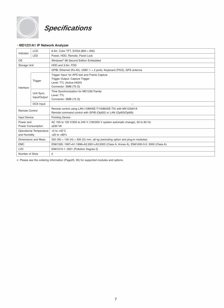
Specifications
IndicatorLCD 8.4in. Color TFT, SVGA (800 × 600)
LED Power, HDD, Remote, Panel Lock
OS Windows® 98 Second Edition Embedded
Storage Unit HDD and 3.5in. FDD
GPIB, Ethernet (RJ-45), USB1.1 × 2 ports, Keyboard (PS/2), GPS antenna
Trigger Input: for APS test and Frame Capture
TriggerTrigger Output: Capture TriggerLevel: TTL (Active HIGH)
Interface Connector: SMB (75 Ω)
Unit Sync.Time Synchronization for MD1230 Family
Input/OutputLevel: TTLConnector: SMB (75 Ω)
DCS Input —
Remote ControlRemote control using LAN (10BASE-T/100BASE-TX) with MX123001ARemote command control with GPIB (Opt02) or LAN (Opt03/Opt06)
Input Device Pointing Device
Power and AC 100 to 120 V/200 to 240 V (100/200 V system automatic change), 50 to 60 HzPower Consumption ≤330 VA
Operational Temperature +5 to +40˚Cand Humidity +20 to +80%
Dimensions and Mass 320 (W) × 100 (H) × 300 (D) mm, ≤6 kg (excluding option and plug-in modules)
EMC EN61326: 1997+A1:1998+A2:2001+A3:2003 (Class A, Annex A), EN61000-3-2: 2000 (Class A)
LVD EN61010-1: 2001 (Pollution Degree 2)
Number of Slots 2
• MD1231A1 IP Network Analyzer
∗: Please see the ordering information (Page25, 26) for supported modules and options.

8
MP1590B Network Performance Tester
Test Window: Switches test window screen between full and
1/4 split screens.
Setup: Switches between setup and test window screens.
Pointer: Same function as mouse.
Cursor
Set: Sets data.
Cancel: Cancel data setting.
< >: Scrolls screen cursor.
Keys: Inputs numeric data
Tree View: On/Off for tree view area
H.Reset: Resets history data
USB Connector: Connector for USB devices.
Keyboard: Connector for external keyboard.
Error: Starts/stops error insertion.
Alarm: Starts/stops alarm insertion.
Run/Stop: Starts/stops measurements and tests.
Compact Flash Card: Compact flash memory interface.
Power: When the power indicator is on, the MP1590B
application ends, it automatically changes to standby
condition. In standby condition (when the standby indicator is
on), the MP1590B application software can be started and
operated.
Screen Copy: Copies the displayed screen to a disk file.
Help: Displays the help screen
Microphone: Microphone for order wire
Laser
Key Switch: Switches optical signals "On" and
"communication Off".
Remote Interlock: Connector for laser remote interlock.
Trigger
Input: Input connector for external trigger to control APS test
and capture.
Output: Output connector for error/alarm and capture trigger.
Power (Main Power): Switches MP1590B power on and off.
CLK Source
Input: Reference signal input connector for synchronizing
the transmission signal with an external reference signal.
Output: Reference signal output connector for synchronizing
the transmission signal with an external reference signal.
RS-232C: RS-232C remote control interface.
Ethernet: 10BASE-T/100BASE-TX Ethernet remote control
interface.
GPIB: GPIB remote control interface.
VIDEO: Connector for external VGA display.
DCC/GCC: Connector for data/clock input/output for
DCC (SDH/SONET), GCC (OTN byte) or add/drop data.
9
Specifications
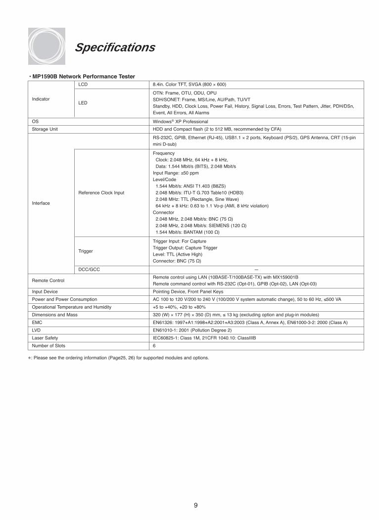
• MP1590B Network Performance Tester
Indicator
LCD 8.4in. Color TFT, SVGA (800 × 600)
LED
OTN: Frame, OTU, ODU, OPUSDH/SONET: Frame, MS/Line, AU/Path, TU/VTStandby, HDD, Clock Loss, Power Fail, History, Signal Loss, Errors, Test Pattern, Jitter, PDH/DSn,Event, All Errors, All Alarms
OS Windows® XP Professional
Storage Unit HDD and Compact flash (2 to 512 MB, recommended by CFA)
Interface
RS-232C, GPIB, Ethernet (RJ-45), USB1.1 × 2 ports, Keyboard (PS/2), GPS Antenna, CRT (15-pinmini D-sub)
Reference Clock Input
FrequencyClock: 2.048 MHz, 64 kHz + 8 kHz,Data: 1.544 Mbit/s (BITS), 2.048 Mbit/s
Input Range: ±50 ppmLevel/Code
1.544 Mbit/s: ANSI T1.403 (B8ZS)2.048 Mbit/s: ITU-T G.703 Table10 (HDB3)2.048 MHz: TTL (Rectangle, Sine Wave)64 kHz + 8 kHz: 0.63 to 1.1 Vo-p (AMI, 8 kHz violation)
Connector2.048 MHz, 2.048 Mbit/s: BNC (75 Ω)2.048 MHz, 2.048 Mbit/s: SIEMENS (120 Ω)1.544 Mbit/s: BANTAM (100 Ω)
Trigger
Trigger Input: For CaptureTrigger Output: Capture TriggerLevel: TTL (Active High)Connector: BNC (75 Ω)
DCC/GCC —
Remote ControlRemote control using LAN (10BASE-T/100BASE-TX) with MX159001BRemote command control with RS-232C (Opt-01), GPIB (Opt-02), LAN (Opt-03)
Input Device Pointing Device, Front Panel Keys
Power and Power Consumption AC 100 to 120 V/200 to 240 V (100/200 V system automatic change), 50 to 60 Hz, ≤500 VA
Operational Temperature and Humidity +5 to +40%, +20 to +80%
Dimensions and Mass 320 (W) × 177 (H) × 350 (D) mm, ≤ 13 kg (excluding option and plug-in modules)
EMC EN61326: 1997+A1:1998+A2:2001+A3:2003 (Class A, Annex A), EN61000-3-2: 2000 (Class A)
LVD EN61010-1: 2001 (Pollution Degree 2)
Laser Safety IEC60825-1: Class 1M, 21CFR 1040.10: ClassIIIB
Number of Slots 6
∗: Please see the ordering information (Page25, 26) for supported modules and options.

10
MP1591A Network Performance Tester
Power Switch: Power switch of the MP1591A.
Functional Ground Terminal: This terminal is connected
electrically to the MP1591A cabinet.
Ethernet: Connector used to connect the MP1591A with an
external controller via Ethernet interface (10BASE-T or
100BASE-TX).
LED: Lights up green when the control board is ready.
RS-232C Connector: Connector used to connect the
MP1591A and an external control PC via RS-232C interface.
Order Wire (RJ11): Connector for order wire interface using
SDH/SONET bytes E1 and E2.
Trigger:
Input: Input connector for inputting an external trigger for exe-
cuting APS tests and OH sequence capture.
Output: Output connector for outputting errors, alarms, syn-
chronous frames, and SONET synchronous dividing clocks
detected on the reception side.
Unit Sync. Input/Output: Unit sync. input/output connector
for inputting clock signals used for establishing time synchro-
nization among the MP1591A and MD1230 family units when
the MP1591A is connected in a daisy chain.
CLK Source:
Input: Reference signal input connector for synchronizing
transmission signals with external reference signals
Output: Reference signal output connector for synchronizing
transmission signals with external reference signals.
DCC/GCC Connector: Input/output connector for D1 to D3,
D4 to D12, and GCC0 to GCC2 data

11
Specifications
• MP1591A Network Performance Tester
Interface
Ethernet (RJ-45) × 2
Reference Clock Input
FrequencyClock: 2.048 MHz, 64 kHz + 8 kHz,Data: 1.544 Mbit/s (BITS), 2.048 Mbit/s
Input Range: ±50 ppmLevel/Code
1.544 Mbit/s: ANSI T1.403 (B8ZS)2.048 Mbit/s: ITU-T G.703 Table10 (HDB3)2.048 MHz: TTL (Rectangle, Sine Wave)64 kHz + 8 kHz: 0.63 to 1.1 Vo-p (AMI, 8 kHz violation)
Connector2.048 MHz, 2.048 Mbit/s: BNC (75 Ω)2.048 MHz, 2.048 Mbit/s: SIEMENS (120 Ω)1.544 Mbit/s: BANTAM (100 Ω)
Trigger
Trigger Input: For CaptureTrigger Output: Capture TriggerLevel: TTL (Active High)Connector: BNC (75 Ω)
Unit Sync. Input/OutputTime Synchronization Level: TTLConnector: BNC (75 Ω)
Remote Control Remote control using LAN (10BASE-T/100BASE- TX) with MX159001B∗1
Input Device AC 100 to 120 V/200 to 240 V (100/200 V system automatic change), 50 to 60 Hz, ≤2200 VA
Power and Power Consumption AC 100 to 120 V/200 to 240 V (100/200 V system automatic change), 50 to 60 Hz, ≤500 VA
Operational Temperature and Humidity +5 to +40%, +20 to +80%
Dimensions and Mass 320 (W) × 177 (H) × 350 (D) mm, ≤ 13 kg (excluding option and plug-in modules)
EMC EN61326: 1997+A1:1998+A2:2001+A3:2003 (Class A, Annex A), EN61000-3-2: 2000 (Class A)
LVD EN61010-1: 2001 (Pollution Degree 2)
Laser Safety IEC60825-1: Class 1M, 21CFR 1040.10: ClassIIIB
Number of Slots 16
∗1 : Requires MX159001B for the control of MP1591A.
∗ : Please see the ordering information (Page25, 26) for supported modules and options.
• MU159101A Control Module
• MU159103A Interface Module for Expansion Slot
LED Ready
Interface RS-232C (for Self test, Download)
Number of Support Modules 8
Interface
Reference Clock Input
Same as MP1591A.Trigger
Unit Sync. Input/Output

Model MU120131A MU120132A
Name 10/100/1000M Ethernet Module Gigabit Ethernet Module
Corresponding Specification 10BASE-T, 100BASE-TX, 1000BASE-T 1000BASE-SX/LX/LE/LR (depend on SFP Module)
Connector RJ-45 SFP (LC)
Number of Ports 12 SFP: 8
Bit Rate 10, 100, 1000 Mbit/s 1000 Mbit/s
Duplex Mode Full/Half Full
Auto Negotiation On/Off On/Off
Flow Control On/Off On/Off
LED Link
Clock Variation On/Off, Resolution 1 ppm, –100 ppm to +100 ppm settable. (Module-Opt01) Clock Accuracy: MD1230B: ±4 ppm, MP1590B/MP1591A: ±0.1 ppm
Clock Measurement Without 10BASE-T, Accuracy: MD1230B: ±4 ppm, MP1590B/MP1591A: ±0.1 ppm(Module-Opt01)
ModeNormal, Monitor, Through (port 1 and port 2, port 3 and port 4, port 5 and port 6, port 7 and port 8, port 9 and port 10,port 11 and port 12), Address Swap
PoE (Module- Opt02) Off (0 to 30 V)/ Under (31 to 42 V)/ Normal (43 V) —
Link Up/Down On/Off/Flap (10 to 3600 s, 1 to 65536 times, Infinite), No/Go Judgment
Frame Generation (TxStream)
Number of Streams 256 Streams/Port
Stream Transport Mode: Continuous, Continuous Burst, Stop after this Stream, Next Stream, Jump to Stream, Jump to Stream Stream for Count (Loop Count: 1 to 16,000,000)
Setting Frame per Burst 1 to 16,777,215
Burst per Stream 1 to 1,099,511,627,775
1000BASE-T: Resolution of 8 ns, 80 ns to 120 s Settable as 1000BASE-T: Resolution of 8 ns, 64 ns to 120 s Settable as Fixed or Random, 100BASE-TX: Resolution of 80 ns, Fixed or Random.
Inter Frame Gap 800 ns to 1200 s Settable as Fixed or Random, 10BASE-T: Resolution of 800 ns, 8 μs to 12000 s Settable asFixed or Random.
Gap 1000BASE-T: Resolution of 8 ns, 80 ns to 120 s Settable as 1000BASE-T: Resolution of 8 ns, 64 ns to 120 s Settable as Fixed, 100BASE-TX: Resolution of 80 ns, 800 ns to 1200 s Fixed.
Setting
Inter Burst GapSettable as Fixed, 10BASE-T: Resolution of 800 ns, 8 μs to 12000 s Settable as Fixed
1000BASE-T: Resolution of 8 ns, 80 ns to 120 s Settable as 1000BASE-T: Resolution of 8 ns, 64 ns to 120 s Settable as Fixed, 100BASE-TX: Resolution of 80 ns, 800 ns to 120 s Fixed.Inter Stream GapSettable as Fixed, 10BASE-T: Resolution of 800 ns, 8 μs to12000 s Settable as Fixed
Preamble Size: 4 to 255 byte Preamble Size: 2 to 255 byte, Supports E-PON Preamble
MAC Address: Fixed, Increment, Decrement, Random (Changeable portion specified in 4 bits units) VLAN tag∗1: Up to 10 layer VLAN tags can be appended. VLAN ID can be set Increment, Decrement, Random.MPLS label∗1: Up to 10 MPLS labels can be appended. Fixed setting.Protocol Editing: None, ARP, IPv4, IGMP/IPv4, ICMP/IPv4, TCP/IPv4, UDP/IPv4, RIP/UDP/IPv4, DHCP/UDP/IPv4, IPv6, IPX,
IS-IS, MAC Control Frame (Pause Frame)Support by IPv6 Expansion (Opt12): ICMPv6/IPv6, TCP/IPv6, UDP/IPv6, IPv6 over IPv4, ICMPv6/IPv6 over IPv4, TCP/IPv6
over IPv4, UDP/IPv6 over IPv4Supported by PIM-SMv2 Protocol (Opt21): PIM Register Message
Frame Setting Supported by MLDA Protocol (Opt22): ICMPv6 MLDA Type MessageSupported by Spanning Tree/Link Aggregation (Opt23): STP Configuration BPDU, STP TCN BPDU, RST BPDU, MST BPDU,
LACPDU, Marker PDU, Marker Response PDUIPv4/IPv6 : IP Destination/Source Address can be set Fixed, Increment, Decrement, Random independently. TCP/UDP: Either Destination Port Number or Source Port Number can be set Increment, Random. Data Field: Can set any portions of data field as All 0, All 1, Alternate1/0 (Each bit, Each 2bits, Each 4bits, Each 1 Byte, Each 2
Bytes), Increment, Decrement, Random.Only Data Field 1 can set Programmable, Single PRBS9, Time Stamp∗2, Sequence Number∗2, Hardware Random Pattern∗2, Test Frame. Settable Flow ID number when Test Frame is used.Programmable Header Pattern: 1 user defined pattern can be set.
Frame Size 48 to 10,000 byte, Settable as Auto, Fixed, Increment∗3, or Random∗3
EthernetFCS Error, Undersize, Oversize, Fragment, Oversize & FCS Error
Dribble Bit Error, Alignment Error, Collision E-PON Preamble CRC ErrorError
IP IPv4 Header Checksum ErrorInsertionTCP/UDP TCP/UDP Checksum Error
Data (Opt11) PRBS Error (Single PRBS9, PRBS23, 31)
Test Pattern (Electrical): All 0, All 1, User 16, PRBS23, PRBS31
Unframed BER SettingTest Pattern (Optical): All 0, All 1, User 16, PRBS23, PRBS31, CJPAT, CRPATError Insertion: Bit AllInsertion Timing: Single, Rate (1.0E-9, 1.0E-8, 1.0E-7, 1.0E-6, 1.0E-5, 1.0E-4, 1.0E-3), Programmable Rate (1.0E-10 to 9.9E-3)
12
• Express Flow Module

13
Model MU120131A MU120132A
Measurement Function
Transmitted/Received Frame Count, Transmitted/Received Frame Rate, Transmitted/Received Bit Count, Transmitted/Received Bit Rate, Transmitted/Received Byte Count, Transmitted/Received Rate, FCS Error, Undersize, Fragment, Oversize, Oversize & FCS Error
EthernetDribble Bit, Alignment Error, Line Error, Collision
Line Error, Flow Control, Transmitted/Received ARP
Flow Control, Transmitted/Received ARP Request, Request, Transmitted/Received ARP Reply
Transmitted/Received ARP ReplyElectrical: Dribble Bit, Alignment Error, CollisionOptical: Byte Alignment Error
IPv4Transmitted/Received IPv4 Packet Count, Transmitted/Received IPv4 Packet Rate, Transmitted/Received Ping Request, Transmitted/Received Ping Reply, IP Header Checksum Error
Transmitted/Received IPv6 Packet Count, Transmitted/ Received IPv6 Packet Rate, Transmitted/Received ICMPv6 (NS) Count, IPv6 (Opt12) Transmitted/Received ICMPv6 (NA) Count, Transmitted/Received ICMPv6 (Echo Request) Count, Transmitted/Received
Counter ICMPv6 (Echo Reply) Count
TCP/UDPReceived TCP Packet Count, Received TCP Packet Rate, Received UDP Packet Count, Received UDP Packet Rate, TCP Checksum Error∗4, UDP Checksum Error∗4
DataCapture Trigger, Capture Filter, User Defined 1 Count/Rate, User Defined 2 Count/Rate, QoS 0 to 7 Frame Count/RateQoS Counter Setting: The target of QoS is IPv4 (ToS) or VLAN tag (Priority).
Packet BER Test Transmitted/Received Test Frame Count, Sequence Error, Received PRBS Error Frame Count/Rate, Received PRBS Error Bit (Opt11) Count/Rate
Unframed BER Bit Error Count/Rate, Pattern Sync. Loss Count/SecondTest
Multi Flow (All Ports) Settable as up to 16 bits filter 4 to count each value at a special frame/bit/byte/rate/latency/sequence error (255Counter flow/port), ex) VLAN ID, Flow ID at test frame and so on. 255 flow/unit counters are supported for real time count.
LatencyWhen Test Frames are received, the latency is indicated. The result includes 1s sampling value, max, min, avg. and number of samples.
Frame Arrival Time/32 counters indicate the result.
Latency DistributionResolution : Frame Arrival Time: 1 μs, 10 μs, 100 μs, 1 ms, 10 ms, 100 ms, 1 s
Latency Distribution: 50 ns, 100 ns, 1 μs, 10 μs, 100 μs, 1 ms, 10 ms, 100 ms
Custom CounterFrame Loss, Frame Loss Rate, Received bit Rate (Mbps), received Average Frame Size (byte), Received Average Gap Size(byte), Received Rate (%)
Capture Buffer 16 MByte/Port
Preamble Capture On/Off
At following conditions for each port, Capture Filter/Trigger condition settings:Capture Filter/Condition: Destination MAC Address, Source MAC Address, 128-bit pattern 1 to 4, ErrorTriggerOnly capture trigger can be set following: Traffic Over, Latency Over, External Trigger, Manual Trigger
Capture Ethernet (Type II, IEEE802.3, Mac Control), VLAN, MPLS, LLC, LACP, BPDU (STP, RST, MST), ARP, IP, IPv6 (include Extended
Decode ProtocolHeader), IPX, OSINL, IS-IS, IGMP (include IGAP), ICMP, ICMPv6 (include NDP, MLD, MLDA) TCP, UDP, OSPF, OSPFv3, DVMRP, LDP (CR-LDP), BGP4, RIP, DHCP, RSVP (RSVP-TE), BGP4+, PIM-SMv2, PPP (include LCP, IPCP, IPV6CP, OSINLCP, MPLSCP), CiscoHDLC, MAPOS, NSP, SSP, Test Frame
Extended By Sniffer® Technologies (Opt04) or MX123002A Expert Analysis Module, the number of decode protocols can be increased upDecode Protocol to 400. MD1230 Family includes Ethereal® Convert Function.
Protocol Emulation ARP, ICMP, ICMPv6 (Opt12), IGMPv2, IGMPv3 (Opt12), IGAP (Opt14), MLD (Opt12), MLDA (Opt22)∗5
Traffic Monitor —
Traffic Map —
Service Disruption Time Time of frame disruption.
Auto Negotiation Analysis —
10B Code data transmitted function, Auto negotiation (Opt15) sequence capture function, Link timer value variable function
Application Traffic MonitorSupport 1 ms traffic monitoring within 4 ports (Max. 4 flows)(Opt20)
RFC2544 Automatic TestFollowing 6 types of tests can be supported with up to 10 layer VLAN tags. (MD1230 Family supports continuous test [1] to [5].)[1] Throughput, [2] Latency, [3] Frame loss rate, [4] Back-to-back frames, [5] System recovery, [6] Reset
Following 10 types of tests can be supported.with up to 10 layer VLAN tags.[1] Fully meshed throughput, frame loss, and forwarding rate, [2] Partially meshed one-to-many/many-to-one, RFC2889 Automatic Test[3] Partially meshed multiple devices, [4] Partially meshed unidirectional traffic, [5] Congestion control, [6] Forward pressure and(Opt10)maximum forwarding rate, [7] Address caching capacity, [8] Address learning rate, [9] Error-frame filtering, [10] Broadcast frame forwarding and latency
∗1: VLAN tag and MPLS labels cannot both be used simultaneously.∗2: When a sequence number or time stamp or hardware random pattern is used, the check sum field of the TCP/UDP packet contains an error code.∗3: Increment and Random settings can be specified for the frame size only when None is selected for the protocol.∗4: The packets fragmented in the IP layer are not counted as error packets.∗5: Option 12 IPv6 Expansion is required.
MU120131A 10/100/1000BASE-T 12 Ports MU120132A 1000BASE-X (SFP) 8 Ports

Model MU120121A MU120122A
Name 10/100/1000M Ethernet Module Gigabit Ethernet Module
Corresponding Specification Electrical: 10BASE-T, 100BASE-TX, 1000BASE-TElectrical: 10BASE-T, 100BASE-TX, 1000BASE-TOptical: 1000BASE-SX/LX/LE/LR (depend on SFP Module)
Connector RJ-45 SFP (LC), RJ-45
Number of Ports 4 SFP: 2, RJ-45: 2
Bit Rate 10, 100, 1000 Mbit/s 10, 100, 1000 Mbit/s
Duplex Mode Full/Half Electrical: Full/Half, Optical: Full
Auto Negotiation On/Off On/Off
Flow Control On/Off On/Off
LED Tx/Collision, Rx/Error, 10 M, 100 M, 1000 M, DuplexElectrical: Tx/Collision, Rx/Error, 10 M, 100 M, 1000 M, DuplexOptical: Link, Tx, Rx, Error
Clock Variation On/Off, Resolution 1 ppm, –100 ppm to +100 ppm settable.(Module-Opt01) Clock Accuracy: ±4 ppm
Clock Measurement Without 10BASE-T, Accuracy: ±4 ppm(Module-Opt01)
Mode Normal, Monitor, Through (port 1 and port 2, port 3 and port 4), Address Swap
Link Up/Down Manual On/Off
Frame Generation (TxStream)
Number of Streams 256 Streams/Port
Stream Transport Mode: Continuous, Continuous Burst, Stop after this Stream, Next Stream, Jump to Stream, Jump to Stream Stream for Count (Loop Count: 1 to 16,000,000)
Setting Frame per Burst 1 to 16,777,215
Burst per Stream 1 to 1,099,511,627,775
Electrical: 1000BASE-T: Resolution of 8 ns, 80 ns to 120 s Settable as Fixed or Random, 100BASE-TX: Resolution of 80 ns, Inter Frame Gap 800 ns to 1200 s Settable as Fixed or Random, 10BASE-T: Resolution of 800 ns, 8 μs to 12000 s Settable as Fixed or Random.
Optical: Resolution of 8 ns, 64 ns to 120 s Settable as Fixed or Random.
Gap Electrical: 1000BASE-T: Resolution of 8 ns, 80 ns to 120 s Settable as Fixed, 100BASE-TX: Resolution of 80 ns, 800 ns to 1200 s
SettingInter Burst Gap Settable as Fixed, 10BASE-T: Resolution of 800 ns, 8 μs to 12000 s Settable as Fixed.
Optical: Resolution of 8 ns, 64 ns to 120 s Settable as Fixed.
Electrical: 1000BASE-T: Resolution of 8 ns, 80 ns to 120 s Settable as Fixed, 100BASE-TX: Resolution of 80 ns, 800 ns to 120 s Inter Stream Gap Settable as Fixed, 10BASE-T: Resolution of 800 ns, 8 μs to 12000 s Settable as Fixed.
Optical: Resolution of 8 ns, 64 ns to 120 s Settable as Fixed.
Preamble Size: 4 to 255 byte Preamble Size: Electrical: 4 to 255 byte, Optical: 2 to 255 byte
MAC Address: Fixed, Increment, Decrement, Random (Changeable portion specified in 4 bits units) VLAN tag∗1: Up to 10 layer VLAN tags can be appended. VLAN ID can be set Increment, Decrement, Random.MPLS label∗1: Up to 10 MPLS labels can be appended. Fixed setting.Protocol Editing: None, ARP, IPv4, IGMP/IPv4, ICMP/IPv4, TCP/IPv4, UDP/IPv4, RIP/UDP/IPv4, DHCP/UDP/IPv4, IPv6, IPX,
IS-IS, MAC Control Frame (Pause Frame)Support by IPv6 Expansion (Opt12): ICMPv6/IPv6, TCP/IPv6, UDP/IPv6, IPv6 over IPv4, ICMPv6/IPv6 over IPv4, TCP/IPv6
over IPv4, UDP/IPv6 over IPv4Supported by PIM-SMv2 Protocol (Opt21): PIM Register Message
Frame Setting Supported by MLDA Protocol (Opt22): ICMPv6 MLDA Type MessageSupported by Spanning Tree/Link Aggregation (Opt23): STP Configuration BPDU, STP TCN BPDU, RST BPDU, MST BPDU,
LACPDU, Marker PDU, Marker Response PDUIPv4/IPv6 : IP Destination/Source Address can be set Fixed, Increment, Decrement, Random independently. TCP/UDP: Either Destination Port Number or Source Port Number can be set Increment, Random. Data Field: Can set any portions of data field as All 0, All 1, Alternate1/0 (Each bit, Each 2bits, Each 4bits, Each 1 Byte, Each 2
Bytes), Increment, Decrement, Random.Only Data Field 1 can set Programmable, Single PRBS9, Time Stamp∗2, Sequence Number∗2, Hardware Random Pattern∗2, Test Frame. Settable Flow ID number when Test Frame is used.Programmable Header Pattern: 1 user defined pattern can be set.
Frame Size 48 to 10,000 byte, Settable as Auto, Fixed, Increment∗3, or Random∗3
EthernetFCS Error, Undersize, Oversize, Fragment, Oversize & FCS Error
Electrical: Dribble Bit Error, Alignment Error, CollisionError
IP IPv4 Header Checksum ErrorInsertionTCP/UDP TCP/UDP Checksum Error
Data (Opt11) PRBS Error
Test Pattern (Electrical): All 0, All 1, User 16, PRBS23, PRBS31
Unframed BER SettingTest Pattern (Optical): All 0, All 1, User 16, PRBS23, PRBS31, CJPAT, CRPATError Insertion: Bit AllInsertion Timing: Single, Rate (1.0E-9, 1.0E-8, 1.0E-7, 1.0E-6, 1.0E-5, 1.0E-4, 1.0E-3), Programmable Rate (1.0E-10 to 9.9E-3)
14
• Power Protocol Module

15
Model MU120121A MU120122A
Measurement Function
Transmitted/Received Frame Count, Transmitted/Received Frame Rate, Transmitted/Received Bit Count, Transmitted/Received Bit Rate, Transmitted/Received Byte Count, Transmitted/Received Rate, FCS Error, Undersize, Fragment, Oversize, Oversize & FCS Error
EthernetDribble Bit, Alignment Error, Line Error, Collision
Line Error, Flow Control, Transmitted/Received ARP
Flow Control, Transmitted/Received ARP Request, Request, Transmitted/Received ARP Reply
Transmitted/Received ARP ReplyElectrical: Dribble Bit, Alignment Error, CollisionOptical: Byte Alignment Error
IPv4Transmitted/Received IPv4 Packet Count, Transmitted/Received IPv4 Packet Rate, Transmitted/Received Ping Request, Transmitted/Received Ping Reply, IP Header Checksum Error
Transmitted/Received IPv6 Packet Count, Transmitted/ Received IPv6 Packet Rate, Transmitted/Received ICMPv6 (NS) Count, IPv6 (Opt12) Transmitted/Received ICMPv6 (NA) Count, Transmitted/Received ICMPv6 (Echo Request) Count, Transmitted/Received
Counter ICMPv6 (Echo Reply) Count
TCP/UDPReceived TCP Packet Count, Received TCP Packet Rate, Received UDP Packet Count, Received UDP Packet Rate, TCP Checksum Error∗4, UDP Checksum Error∗4
DataCapture Trigger, Capture Filter, User Defined 1 Count/Rate, User Defined 2 Count/Rate, QoS 0 to 7 Frame Count/RateQoS Counter Setting: The target of QoS is IPv4 (ToS) or VLAN tag (Priority).
Packet BER Test Transmitted/Received Test Frame Count, Sequence Error, Received PRBS Error Frame Count/Rate, Received PRBS Error Bit (Opt11) Count/Rate
Unframed BER Bit Error Count/Rate, Pattern Sync. Loss Count/SecondTest
Multi Flow (Port 1,2 only) Settable as up to 16 bits filter to count each value at a special bit in frames. (Max 65,536 values)Counter ex) VLAN ID, Flow ID at test frame and so on. 32 of 65,536 counters are supported for real time count.
LatencyWhen Test Frames are received, the latency is indicated. The result includes 1s sampling value, max, min, avg. and number of samples.
Frame Arrival Time/32 counters indicate the result.
Latency DistributionResolution : Frame Arrival Time: 1 μs, 10 μs, 100 μs, 1 ms, 10 ms, 100 ms, 1 s
Latency Distribution: 50 ns, 100 ns, 1 μs, 10 μs, 100 μs, 1 ms, 10 ms, 100 ms
Custom CounterFrame Loss, Frame Loss Rate, Received bit Rate (Mbps), received Average Frame Size (byte), Received Average Gap Size(byte), Received Rate (%)
Capture Buffer 64 MByte/Port
Preamble Capture On/Off
At following conditions for each port, Capture Filter/Trigger condition settings:Capture Filter/Condition: 128-bit pattern 1, 128-bit pattern 4, ErrorTriggerOnly capture trigger can be set following: Traffic Over, Latency Over, External Trigger, Manual Trigger
Capture Ethernet (Type II, IEEE802.3, Mac Control), VLAN, MPLS, LLC, LACP, BPDU (STP, RST, MST), ARP, IP, IPv6 (include Extended
Decode ProtocolHeader), IPX, OSINL, IS-IS, IGMP (include IGAP), ICMP, ICMPv6 (include NDP, MLD, MLDA) TCP, UDP, OSPF, OSPFv3, DVMRP, LDP (CR-LDP), BGP4, RIP, DHCP, RSVP (RSVP-TE), BGP4+, PIM-SMv2, PPP (include LCP, IPCP, IPV6CP, OSINLCP, MPLSCP), CiscoHDLC, MAPOS, NSP, SSP, Test Frame
Extended By Sniffer® Technologies (Opt04) or MX123002A Expert Analysis Module, the number of decode protocols can be increased upDecode Protocol to 400. MD1230 Family includes Ethereal® Convert Function.
Protocol EmulationARP, ICMP, OSPF (Opt07), BGP-4, ICMPv6 (Opt12), OSPFv3 (Opt18)∗5, BGP4+ (Opt19)∗5, IGMP, IGAP (Opt14), MLD (Opt12),MLDA (Opt22)∗5, PIM-SMv2 (Opt21)∗6, MPLS (LDP/CR-LDP) (Opt08), MPLS (RSVP-TE) (Opt09)
Traffic MonitorTraffic Monitor can measure up to 64 streams in real-time.Target : MAC Address, IPv4 Address, IPv6 Address, Protocol Number (include Ether Type and IP Protocol Number)
Traffic Map Traffic Monitor can measure up to 64 streams in real-time. Target : MAC Address, IPv4 Address, IPv6 Address
Service Disruption Time Time of frame disruption.
Auto Negotiation Analysis —
10B Code data transmitted function, Auto negotiation (Opt15) sequence capture function, Link timer value variable function
Application Traffic MonitorSupport 1 ms traffic monitoring within 4 ports (Max. 4 flows)(Opt20)
RFC2544 Automatic TestFollowing 6 types of tests can be supported with up to 10 layer VLAN tags. (MD1230 Family supports continuous test [1] to [5].)[1] Throughput, [2] Latency, [3] Frame loss rate, [4] Back-to-back frames, [5] System recovery, [6] Reset
Following 10 types of tests can be supported.with up to 10 layer VLAN tags.[1] Fully meshed throughput, frame loss, and forwarding rate, [2] Partially meshed one-to-many/many-to-one, [3] Partially meshedRFC2889 Automatic Testmultiple devices, [4] Partially meshed unidirectional traffic, [5] Congestion control, [6] Forward pressure and maximum forwarding(Opt10)rate, [7] Address caching capacity, [8] Address learning rate, [9] Error-frame filtering, [10] Broadcast frame forwarding and latency
∗1: VLAN tag and MPLS labels cannot both be used simultaneously.∗2: When a sequence number or time stamp or hardware random pattern is
used, the check sum field of the TCP/UDP packet contains an error code.∗3: Increment and Random settings can be specified for the frame size only
when None is selected for the protocol.
∗4: The packets fragmented in the IP layer are not counted as error packets.∗5: Option 12 IPv6 Expansion is required.∗6: Option 12 IPv6 Expansion is required when IPv6 addresses are used.
Option 21 supports only IPv4 addresses.
MU120121A 10/100/1000BASE-T 4 Ports MU120122A 10/100/1000BASE-T, X (SFP) 2 Ports

Model MU120111A MU120112A MU120118B/C
Name 10M/100M Ethernet Module Gigabit Ethernet Module 10 Gigabit Ethernet Module
Corresponding Specification 10BASE-T, 100BASE-TX1000BASE-SX/LX/LH/ZX/T 10GBASE-SR/LR/ER(depend on GBIC Module) (depend on XENPAK Module)
Connector RJ-45 GBIC (SC, RJ-45) XENPAK (SC)
Number of Ports 8 2 2 (MU120118B), 1 (MU120118C)
Bit Rate 10 M, 100 Mbit/s 1000 Mbit/s 10 Gbit/s
Duplex Mode Full/Half Full Full
Auto Negotiation On/Off On/Off —
Flow Control On/Off On/Off On/Off
LED Link, Tx/Collision, Rx/Error Link, Tx, Rx, Error Link, Tx, Rx, Error
Mode Normal, Monitor, Through∗1, Address Swap∗2 Normal, Monitor, Through
Optical Output — On/Off On/Off
Frame Generation (TxStream)
Number of Streams 256 Streams / Port
Stream Transport Mode: Continuous, Continuous Burst, Stop after this Stream, Next Stream, Jump to Stream, Jump to Stream Stream for Count (Loop Count: 1 to 16,000,000)
Setting Frame per Burst 1 to 16,777,215 1 to 1,099,511,627,775
Burst per Stream 1 to 16,777,215 1 to 1,099,511,627,775
10BASE-T: Resolution of 800 ns, 8 μs to Resolution of 8 ns, Resolution of 0.8 ns,
Inter Frame Gap1700s Settable as Fixed or Random.
64 ns to 120 s Settable as Fixed or 7.2 ns to 120 s Settable as Fixed or 100BASE-TX: Resolution of 80 ns, 800 nsRandom. Random.to 170 s Settable as Fixed or Random.
10BASE-T: Resolution of 800 ns, 8 μs Gap
Inter Burst Gapto 1700 s Settable as Fixed Resolution of 8 ns, Resolution of 0.8 ns,
Setting 100BASE-TX: Resolution of 80 ns, 800 64 ns to 120 s Settable as Fixed 7.2 ns to 120 s Settable as Fixed.ns to 170 s Settable as Fixed
10BASE-T: Resolution of 800 ns, 8 μs
Inter Stream Gapto 1700 s Settable as Fixed Resolution of 8 ns, Resolution of 0.8 ns, 100BASE-TX: Resolution of 80 ns, 800 64 ns to 120 s Settable as Fixed 64 ns to 120 s Settable as Fixed.ns to 170 s Settable as Fixed
Preamble Size: 4 to 255 byteElectrical: Preamble Size: 2 to 255 byte,
Preamble Size: 2 to 255 byteOptical: Preamble Size: 3 to 255 byte
MAC Address: Fixed, Increment, Decrement, Random (Changeable portion specified in 4 bits units) VLAN tag∗3: 1 layer VLAN tag can be appended. VLAN ID can be set Increment, Decrement, Random.MPLS label∗3: Up to 10 MPLS labels can be appended. Fixed setting.Protocol Editing: None, ARP, IPv4, IGMP/IPv4, ICMP/IPv4, TCP/IPv4, UDP/IPv4, RIP/UDP/IPv4, DHCP/UDP/IPv4, IPv6, IPX,
IS-IS, MAC Control Frame (Pause Frame)Supported by IPv6 Expansion (Opt12): ICMPv6/IPv6, TCP/IPv6, UDP/IPv6, IPv6 over IPv4, ICMPv6/IPv6 over IPv4, TCP/IPv6
over IPv4, UDP/IPv6 over IPv4Supported by PIM-SMv2 Protocol (Opt21): PIM Register MessageFrame SettingSupported by MLDA Protocol (Opt22): ICMPv6 MLDA Type MessageSupported by Spanning Tree/Link Aggregation (Opt23): STP Configuration BPDU, STP TCN BPDU, RST BPDU, MST BPDU,
LACPDU, Marker PDU, Marker Response PDUIPv4/IPv6: IP Destination/Source Address can be set Fixed, Increment, Decrement, Random independently. TCP/UDP: Either Destination Port Number or Source Port Number can be set Increment, Random.Data Field: Can set any portions of data field as All 0, All 1, Alternate1/0 (Each bit, Each 2 bits, Each 4 bits, Each 1 Byte, Each 2
Bytes), Increment, Decrement, Random.Only Data Field 1 can set Programmable, Single PRBS9, Time Stamp∗4, Sequence Number∗4, Test Frame.Programmable Header Pattern: 1 user defined pattern can be set.
18 to 10,000 byte (Settable as Auto, 48 to 65,280 byteFrame SizeFixed, Increment∗5, or Random∗5) (Settable as Auto, Fixed, Increment∗5, or Random∗5)
FCS Error, Undersize, Oversize, Fragment, Oversize & FCS Error
Error
EthernetDribble Bit Error,Alignment Error, Collision —
IP IPv4 Header Checksum ErrorInsertion
TCP/UDP TCP/UDP Checksum Error
Data (Opt11) PRBS Error
Test Pattern: All 0, All 1, User 16, PRBS Test Pattern: All 0, All 1, User 16, PRBS Test Pattern: All 0, All 1, User 16, PRBS23, PRBS31 23, PRBS31, CJPAT, CRPAT 23, PRBS31, CJPAT, CRPATError Insertion: Bit All Error Insertion: Bit All Error Insertion: Bit All, Bit All 0 to 3
Unframed BER Setting∗6 Insertion Timing: Single, Rate (1.0E-9, Insertion Timing: Single, Rate (1.0E-9, Insertion Timing: Single, Rate (1.0E-9,1.0E-8, 1.0E-7, 1.0E-6, 1.0E-5, 1.0E-4, 1.0E-8, 1.0E-7, 1.0E-6, 1.0E-5, 1.0E-4, 1.0E-8, 1.0E-7, 1.0E-6, 1.0E-5, 1.0E-4,1.0E-3), Programmable Rate (1.0E-10 to 1.0E-3), Programmable Rate (1.0E-10 to 1.0E-3), Programmable Rate (1.0E-10 to9.9E-3) 9.9E-3) 9.9E-3)
16
• Basic Module

MU120111A 10/100BASE-T 8 Ports MU120112A 1000BASE-X (GBIC) 2 Ports
17
Model MU120111A MU120112A MU120118B/C
Measurement Function
Transmitted/Received Frame Count, Transmitted/Received Frame Rate, Transmitted/Received Bit Count, Transmitted/Received Bit Rate, Transmitted/Received Byte Count, Transmitted/Received Rate, FCS Error, Undersize, Fragment, Oversize, Oversize &
Ethernet FCS Error, Flow Control, Transmitted/Received ARP Request, Transmitted/Received ARP Reply
Dribble Bit, Alignment Error, Line Error, Byte Alignment Error, Line Error —Collision
IPv4Transmitted/Received IPv4 Packet Count, Transmitted/Received IPv4 Packet Rate, Transmitted/Received Ping Request, Transmitted/Received Ping Reply, IP Header Checksum Error
Transmitted/Received IPv6 Packet Count, Transmitted/ Received IPv6 Packet Rate, Transmitted/Received ICMPv6 (NS) Count, IPv6 (Opt12) Transmitted/Received ICMPv6 (NA) Count, Transmitted/Received ICMPv6 (Echo Request) Count,
Transmitted/Received ICMPv6 (Echo Reply) Count
CounterTCP/UDP
Received TCP Packet Count, Received TCP Packet Rate, Received UDP Packet Count, Received UDP Packet Rate,TCP Checksum Error∗7, UDP Checksum Error∗7
DataCapture Trigger, Capture Filter, User Defined 1 Count/Rate, User Defined 2 Count/Rate, QoS 0 to 7 Frame Count/RateQoS Counter Setting: The target of QoS is IPv4 (ToS) or VLAN tag (Priority).
Packet BER Test Transmitted/Received Test Frame Count, Sequence Error, Received PRBS Error Frame Count/Rate, Received PRBS Error Bit (Opt11) Count/Rate
When XENPAK Test (Opt13) is installed:Unframed BER Lane 0 to 3 Bit Error Count/Rate, Test∗6 Bit Error Count/Rate, Pattern Sync. Loss Count/Second Lane 0 to 3 Pattern Sync. Loss Count/
Second
LFS (Opt16) —Transmitted/Received RF SignalTransmitted/Received LF Signal
LatencyWhen Test Frames are received, the latency is indicated. The result includes 1s sampling value, max, min, avg. and number of samples.
Frame Arrival Time 32 counters indicate the results. Resolution : 1 μs, 10 μs, 100 μs, 1 ms, 10 ms, 100 ms, 1 s.
Capture Buffer 8 MByte/Port 32 MByte/Port 256 MByte/Port
Capture Filter/At following conditions for each port, Capture Filter/Trigger condition settings:
TriggerCondition: Destination MAC Address, Source MAC Address, 128-bit pattern 1, 128-bit pattern 2, ErrorOnly capture trigger can be set following: Traffic Over, Latency Over, External Trigger, Manual Trigger
CaptureEthernet (Type II, IEEE802.3, Mac Control), VLAN, MPLS, LLC, LACP, BPDU (STP, RST, MST), ARP, IP, IPv6 (include Extended
Decode ProtocolHeader), IPX, OSINL, IS-IS, IGMP (include IGAP), ICMP, ICMPv6 (include NDP, MLD, MLDA) TCP, UDP, OSPF, OSPFv3, DVMRP, LDP (CR-LDP), BGP4, RIP, DHCP, RSVP (RSVP-TE), BGP4+, PIM-SMv2, PPP (include LCP, IPCP, IPV6CP, OSINLCP, MPLSCP), CiscoHDLC, MAPOS, NSP, SSP, Test Frame
Extended By Sniffer® Technologies (Opt04) or MX123002A Expert Analysis Module, the number of decode protocols can be increased upDecode Protocol to 400. MD1230 Family includes Ethereal® Convert Function.
ARP, ICMP, OSPF (Opt07), BGP-4, ICMPv6 (Opt12), OSPFv3 (Opt18)∗8, BGP4+ (Opt19)∗8, IGMPv2, IGMPv3 (Opt12), Protocol Emulation IGAP (Opt14), MLD (Opt12), MLDv2 (Opt12), MLDA (Opt22)∗8, PIM-SMv2 (Opt21)∗9, MPLS (LDP/CR-LDP) (Opt08), MPLS
(RSVP-TE) (Opt09)
Traffic MonitorTraffic Monitor can measure up to 64 streams in real-time.Target : MAC Address, IPv4 Address, IPv6 Address, Protocol Number (include Ether Type and IP Protocol Number)
Traffic Map Traffic Monitor can measure up to 64 streams in real-time. Target : MAC Address, IPv4 Address, IPv6 Address
Service Disruption Time Time of frame disruption.
Auto Negotiation Analysis 10B Code data transmitted function, Auto
(Opt15) — negotiation sequence capture function, —Link timer value variable function
Application Traffic Monitor —
Support 1ms traffic monitoring within 2 —(Opt20) ports on 2 modules.
Link Fault Signalling (Opt16) — —LF, RF, User Defined Signal TxXGMII Signal Capture
RFC2544 Automatic TestFollowing 6 types of tests can be supported with 1 layer VLAN tag. (MD1230 Family supports continuous test [1] to [5].)[1] Throughput, [2] Latency, [3] Frame loss rate, [4] Back-to-back frames, [5] System recovery, [6] Reset
Following 10 types of tests can be supported.with 1 layer VLAN tag.[1] Fully meshed throughput, frame loss, and forwarding rate, [2] Partially meshed one-to-many/many-to-one,RFC2889 Automatic Test[3] Partially meshed multiple devices, [4] Partially meshed unidirectional traffic, [5] Congestion control, [6] Forward pressure and (Opt10)maximum forwarding rate, [7] Address caching capacity, [8] Address learning rate, [9] Error-frame filtering, [10] Broadcast frame forwarding and latency
∗1: On MU120111A, the Through mode can be used with port 1 and port 2,and with port 5 and port 6.
∗2: On MU120111A, the Address Swap mode can be used with port 1 and port 5.∗3: VLAN tag and MPLS labels cannot both be used simultaneously.∗4: When a sequence number or time stamp is used, the check sum field of
the TCP/UDP packet contains an error code.∗5: Increment and Random settings can be specified for the frame size only
when None is selected for the protocol.
∗6: Only port 1 or 5 can be used for the unframed BER test on theMU120111A.
∗7: On MU120111A, the packets fragmented in the IP layer are counted aserror packets. On MU120102A and MU120118B/C, they are not countedas error packets.
∗8: Option 12 IPv6 Expansion is required.∗9: Option 12 IPv6 Expansion is required when IPv6 addresses are used.
Option 21 supports only IPv4 addresses.
MU120118B 10GBASE-X (XENPAK) 2 Ports MU120118C 10GBASE-X (XENPAK) 2 Ports

18
Model MU120103B MU120104B
Name 2.5G (1.31) Module 2.5G (1.55) Module
Corresponding Specification OC-48/STM-16
Wavelength 1,260 to 1,360 nm 1,500 to 1,580 nm
Connector SC
Number of Ports 1
Bit Rate 2,488.320 Mbit/s (NRZ)
Output Level –5 to 0 dBm –2 to +3 dBm
Input Sensitivity –18 to 0 dBm –28 to –9 dBm
Clock Internal (±50 ppm Variable), Receive, Lock (64 kHz + 8 kHz, 1.5 MHz, 2 MHz, 1.5 Mbit/s, 2 Mbit/s)
LED Link, Tx, Rx, Error, Optical Send
SONET/SDH Setting
Frame SONET/SDH
PPP Scramble On/Off
Alarm AdditionLOS, LOF, AIS-L/MS-AIS, RDI-L/MS-RDI, TIM-L/MS-TIM, AIS-P/AU-AIS, LOP-P/AU-LOP, RDI-P/HP-RDI, PLM-P/HP-SLM, TIM-P/HP-TIM, UNEQ-P/HP-UNEQ
Alarm Addition Timing Single, Single Burst Frame (Burst Size: 1 to 64,000), Alternative (Alarm Frame: 0 to 8,000, Normal Frame: 1 to 8,000), All
Error Insertion FAS, B1, B2, B3, REI-P/MS-REI, REI-P/HP-REI, HP-IEC, Bit All, Bit Info.
Error Insertion TimingSingle, Single Burst Bit (Burst Size: 1 to 64,000), Rate (1.0E-9, 1.0E-8, 1.0E-7,1.0E-6,1.0E-5, 1.0E-4, 1.0E-3),Programmed Rate (A∗E-B I A: 1.0 to 9.9, B: 3 to 10), All
APS Sequence Generation K1/K2: 2 to 64 Words, Repeat 1 to 8000 Frame/Word, Single or Repeat generation.
Mapping
Frame Generation (TxStream)
Number of Stream 256 Streams/Port
Stream Transport Mode: Continuous, Continuous Burst, Stop after this Stream, Next Stream, Jump to Stream, Jump to Stream
Stream for Count (Loop Count: 1 to 16,000,000)
Setting Frame per Burst 1 to 1,099,511,627,775
Burst per Stream 1 to 1,099,511,627,775
Inter Frame PPP/LEX/LAPS: Resolution of 3.3 ns, 3.3 ns to 120 s Settable as Fixed or Random.∗4
Gap∗3 GFP: Resolution of 13.4 ns, 0 ns to 120 s Settable as Fixed or Random.
Gap Inter Burst PPP/LEX/LAPS: Resolution of 3.3 ns, 3.3 ns to 120 s Settable as Fixed. Setting Gap∗3 GFP: Resolution of 13.4 ns, 53.5 ns to 120 s Settable as Fixed or Random.
Inter Stream PPP/LEX/LAPS: Resolution of 3.3 ns, 267.1 ns to 120 s Settable as Fixed.Gap∗3 GFP: Resolution of 13.4 ns, 267.1 ns to 120 s Settable as Fixed or Random.
FCS: CRC32, CRC16MAC Address: Fixed, Increment, Decrement, Random (Changeable portion specified in 4 bits units) VLAN tag∗5: Up to 1 layer VLAN tags can be appended. VLAN ID can be set Increment, Decrement, Random.MPLS label∗5: Up to 10 MPLS labels can be appended. Fixed setting.Protocol Editing: None, IPv4, TCP/IPv4, UDP/IPv4, IGMP/IPv4, ICMP/IPv4, RIP/UDP/IPv4, DHCP/UDP/IPv4, IPv6, IPX, ARP,
MAC Control, IS-IS, LEX Control Packet∗6, GFP, PPP, EthernetFrame SettingIPv4/IPv6 : IP Destination/Source Address can be set Fixed, Increment, Decrement, Random independently.∗7
TCP/UDP: Either Destination Port Number or Source Port Number can be set Increment, Random.Data Field: Can set any portions of data field as All 0, All 1, Alternate1/0 (Each bit, Each 2bits, Each 4bits, Each 1 Byte, Each 2
Bytes), Increment, Decrement, Random.Only Data Field 1 can set Programmable, Single PRBS9, Time Stamp∗8, Sequence Number∗8, Test Frame.
Programmable Header Pattern: 1 user defined pattern can be set.
Frame Size 8 to 65,535 byte. Settable as Auto, Fixed, Increment∗9, or Random∗9
PPP FCS Error, Undersize, Oversize, Fragment, Oversize & FCS Error, Aborted Frame
GFP∗1Correctable cHEC Error, Uncorrected cHEC Error, Correctable tHEC Error, Uncorrected tHEC Error, Correctable eHEC Error, Uncorrected eHEC Error, FCS Error, Ethernet: FCS Error, Undersize, Oversize, Fragment, Oversize & FCS Error
Error LAPS∗1 FCS Error, Aborted Frame ,Ethernet: FCS Error, Undersize, Oversize, Fragment, Oversize & FCS Error
Insertion LEX∗1 FCS Error, Undersize, Oversize, Fragment, Oversize & FCS Error, Aborted Frame, Ethernet: Undersize
IP IPv4 Header Checksum Error
TCP/UDP TCP/UDP Checksum Error
Data (Opt11) PRBS Error
Test Pattern: PRBS23, PRBS31Unframed BER Setting Error Insertion: Bit All
Insertion Timing: Single, Rate(1.0E-9, 1.0E-8, 1.0E-7, 1.0E-6, 1.0E-5, 1.0E-4, 1.0E-3), Programmable Rate (1.0E-10 to 9.9E-3)
• EoS Module
PPP
(a)
(a)
Bulk
MAPOS Version1
(b)
MAPOS 16
OC-48c
Unframed (b)
F-GFP
LEX
LAPS
VC4
VC3
CiscoHDLC
STM-16c
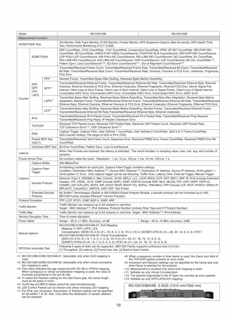
Model MU120103B MU120104B
Measurement Function
SONET/SDH TestOH Monitor, Path Trace Monitor, K1/K2 Monitor, Pointer Monitor, APS Sequence Capture (Max 64 words), APS Switch Time Test, Performance Monitoring (ITU-T G.826)
NDF Count/Rate, +PJC Count/Rate, –PJC Count/Rate, Consecutive Count/Rate, PPM, HP-IEC Count/Rate, REI-P/HP-REI Count/Rate, B3 Count/Rate, UNEQ-P/HP-UNEQ Count/Second, PLM-P/HP-SLM Count/Second, RDI-P/HP-RDI Count/Second,
SONET/SDH LOP-P/AU-LOP Count/Second, AIS-P/AU-AIS Count/Second, REI-L/MS-REI Count/Second, B2 Count/Rate, B1 Count/Rate, RDI-L/MS-RDI Count/Second, AIS-L/MS-AIS Count/Second, OOF Count/Second, LOF Count/Second, Bit Info. Count/Rate∗10, Pattern Sync. Loss Count/Second∗10, SQ Error Count/Second∗11, Out of Alignment Count/Second∗11
Transmitted/Received Frame Count, Transmitted/Received Frame Rate, Transmitted/Received Bit Count, Transmitted/Received Bit Rate, Transmitted/Received Byte Count, Transmitted/Received Rate, Oversize, Oversize & FCS Error, Undersize, Fragments, FCS Error
PPP Aborted Frame, Transmitted Bytes After Stuffing, Received Bytes Before Destuffing
Transmitted/Received Ethernet Frame, Transmitted/Received Ethernet Bit Rate, Transmitted/Received Ethernet Byte, Ethernet PPP, Oversize, Ethernet Oversize & FCS Error, Ethernet Undersize, Ethernet Fragments, Ethernet FCS Error, Server Signal Fail GFP, GFP∗1Interval, Client Loss of Sync Frame, Client Loss of Sync Interval, Client Loss of Signal Frame, Client Loss of Signal Interval, LEX, Correctable cHEC Error, Uncorrected cHEC Error, Correctable tHEC Error, Uncorrected tHEC Error, eHEC Error
LAPSTransmitted Bytes After Stuffing, Received Bytes Before Destuffing, Transmitted Byte After Adaptation, Received Byte Before Counter
LAPS∗1 Adaptation, Aborted Frame, Transmitted/Received Ethernet Frame, Transmitted/Received Ethernet Bit Rate, Transmitted/ReceivedEthernet Byte, Ethernet Oversize, Ethernet Oversize & FCS Error, Ethernet Undersize, Ethernet Fragments, Ethernet FCS Error
LEX∗1Transmitted Bytes After Stuffing, Received Bytes Before Destuffing, Aborted Frame, Transmitted/Received Ethernet Frame, Transmitted/Received Ethernet Bit Rate,Transmitted/Received Ethernet Byte, Ethernet Undersize
IPv4Transmitted/Received IPv4 Packet Count, Transmitted/Received IPv4 Packet Rate, Transmitted/Received Ping Request, Transmitted/Received Ping Reply, IP Header Checksum Error
TCP/UDPReceived TCP Packet Count, Received TCP Packet Rate, Received UDP Packet Count, Received UDP Packet Rate,TCP Checksum Error∗12, UDP Checksum Error∗12
DataCapture Trigger, Capture Filter, User Defined 1 Count/Rate, User Defined 2 Count/Rate, QoS 0 to 7 Frame Count/RateQoS Counter Setting: The target of QoS is IPv4 (ToS).
Packet BER Test Transmitted/Received Test Frame Count, Sequence Error, Received PRBS Error Frame Count/Rate, Received PRBS Error Bit (Opt11) Count/Rate
Unframed BER Test Bit Error Count/Rate, Pattern Sync. Loss Count/Second
LatencyWhen Test Frames are received, the latency is indicated. The result includes 1s sampling value, max, min, avg. and number of samples.
Frame Arrival Time 32 counters make the result. Resolution : 1 μs, 10 μs, 100 μs, 1 ms, 10 ms, 100 ms, 1 s.
Capture Buffer 256 MByte/Port
At following conditions for each port, Capture Filter/Trigger condition settings:Capture Filter/Condition: Destination MAC Address∗13, Source MAC Address∗13, Destination IP Address, Source IP Address, 32-bit pattern 1,Trigger32-bit pattern 2, Error, Only capture trigger can be set following: Traffic Over, Latency Over, External Trigger, Manual Trigger
Capture Ethernet (Type II, IEEE802.3, Mac Control), VLAN, MPLS, LLC, LACP, BPDU (STP, RST, MST), ARP, IP, IPv6 (include Extended Header), IPX, OSINL, IS-IS, IGMP (include IGAP), ICMP, ICMPv6 (include NDP, MLD, MLDA) TCP, UDP, OSPF, OSPFv3, Decode ProtocolDVMRP, LDP (CR-LDP), BGP4, RIP, DHCP, RSVP (RSVP-TE), BGP4+, PIM-SMv2, PPP (include LCP, IPCP, IPV6CP, OSINLCP, MPLSCP), CiscoHDLC, MAPOS, NSP, SSP, Test Frame
Extended Decode By Sniffer® Technologies (Opt04) or MX123002A Expert Analysis Module, a decode protocol can be increased up to 400.Protocol MD1230 Family includes Ethereal® Convert Function.
Protocol Emulation PPP (LCP, IPCP), ICMP, BGP-4, IGMP, ARP
Traffic MonitorTraffic Monitor can measure up to 64 streams in real-time.Target : MAC Address∗13, IPv4 Address, Protocol Number (include Ether Type and IP Protocol Number)
Traffic Map Traffic Monitor can measure up to 64 streams in real-time. Target : MAC Address∗13, IPv4 Address
Service Disruption Time Time of frame disruption.
Power Meter Range: –25 to +1 dBm, Accuracy: ±2 dB Range: –35 to –9 dBm, Accuracy: ±2dB
MU120103B-01/MU120104B-01: EoS MappingMapping: F-GFP, LAPS, LEX, Concatenation: [SDH] VC-4-Xc (X = 16, 8, 4, 3, 2), VC-4, VC-3, [SONET] STS-Xc (X = 48, 24, 12, 9, 6, 3), STS-1Module Options
MU120103B-02/MU120104B-02: Virtual Concatenation[SDH] VC-4-Xv (X = 8, 7, 6, 5, 4, 3, 2), VC-3-Xv (X = 24, 21, 18, 15, 12, 9, 6, 3)[SONET] STS3c-Xv (X = 8, 7, 6, 5, 4, 3, 2), STS1-Xv (X = 24, 21, 18, 15, 12, 9, 6, 3)
RFC2544 Automatic TestFollowing 6 types of tests can be supported. (MD1230 Family supports continuous test [1] to [4].)[1] Throughput, [2] Latency, [3] Frame loss rate, [4] Back-to-back frames
19
∗1: MU120103B-01/MU120104B-01: Selectable only when EoS mapping isused.
∗2: MU120103B-02/MU120104B-02: Selectable only when virtual concatena-tion mapping is used.
∗3: This value indicates the gap measured with OC-48 or STM16 mapping.When contiguous or virtual concatenation mapping is used, the value isinversely proportional to the set bit rate.
∗4: To select the Random setting for the inter-frame gap, the frame lengthmust be 64 bytes or more.
∗5: VLAN tag and MPLS labels cannot be used simultaneously.∗6: LEX Control Packet can be chosen only when choosing LEX mapping.∗7: For IPv6, any Increment, Decrement, or Random setting can be specified
for bit widths 1 to 32. Also, only either the destination or sender addresscan be selected.
∗8: When a sequence number or time stamp is used, the check sum field ofthe TCP/UDP packet contains an error code.
∗9: Increment and Random settings can be specified for the frame size onlywhen None is selected for the protocol.
∗10: Measurement is enabled only when bulk mapping is used.∗11: Settable as only Virtual Concatenation.∗12: The packets fragmented in the IP layer are counted as error packets.∗13: Settable as only GFP/LAPS/LEX mapping.
MU120103B/04B 2.5GG (1310 nm/1550 nm)

20
Model MU120103A MU120104A MU120105A MU120106A
Name 2.5G (1.31) Module 2.5G (1.55) Module 10G (1.31) Module 10G (1.55) Module
Corresponding Specification OC-48/STM-16 OC-192/STM-64
Wavelength 1,260 to 1,360 nm 1,500 to 1,580 nm 1,290 to 1,330 nm 1,530 to 1,565 nm
Connector SC
Number of Ports 1 Port
Bit Rate 2,488.320 Mbit/s (NRZ) 9,953.280 Mbit/s (NRZ)
Output Level –5 to 0 dBm –2 to +3 dBm –4 to 0 dBm –1 to +2 dBm
Input Sensitivity –18 to 0 dBm –28 to –9 dBm –12 to 0 dBm –14 to –3 dBm
ClockInternal (±50 ppm Variable), Receive, Internal (±100 ppm Variable), Receive,Lock (64 kHz + 8 kHz, 1.5 MHz, 2 MHz, 1.5 Mbit/s, 2 Mbit/s) Lock (64 kHz + 8 kHz, 1.5 MHz, 2 MHz, 1.5 Mbit/s, 2 Mbit/s)
LED Link, Tx, Rx, Error, Optical Send
SONET/SDH Setting
Frame SONET/SDH
PPP Scramble On/Off
Alarm AdditionLOS, LOF, AIS-L/MS-AIS, RDI-L/MS-RDI, TIM-L/MS-TIM, AIS-P/AU-AIS, LOP-P/AU-LOP, RDI-P/HP-RDI, PLM-P/HP-SLM, TIM-P/HP-TIM, UNEQ-P/HP-UNEQ
Alarm Addition Timing Single, Single Burst Frame (Burst Size: 1 to 64,000), Alternative (Alarm Frame: 0 to 8,000, Normal Frame: 1 to 8,000), All
Error Insertion FAS, B1, B2, B3, REI-P/MS-REI, REI-P/HP-REI, HP-IEC, Bit All, Bit Info.
Error Insertion TimingSingle, Single Burst Bit (Burst Size: 1 to 64,000), Rate (1.0E-9, 1.0E-8, 1.0E-7,1.0E-6,1.0E-5, 1.0E-4, 1.0E-3),Programmed Rate (A∗E-B I A: 1.0 to 9.9, B: 3 to 10), All
APS Sequence Generation K1/K2: 2 to 64 Words, Repeat 1 to 8000 Frame/Word, Single or Repeat generation.
Mapping
Frame Generation (TxStream)
Number of Streams 256 Streams/Port
Stream Transport Mode: Continuous, Continuous Burst, Stop after this Stream, Next Stream, Jump to Stream, Jump to Stream
Stream for Count (Loop Count: 1 to 16,000,000)
Setting Frame per Burst 1 to 1,099,511,627,775
Burst per Stream 1 to 1,099,511,627,775
Inter Frame GapResolution of 3.3 ns, 3.3 ns to 120 s Settable as Fixed or Resolution of 0.8 ns, 0.8 ns to 120 s Settable as Fixed or
Gap Random∗1. Random∗1.
Setting Inter Burst Gap Resolution of 3.3 ns, 3.3 ns to 120 s Settable as Fixed. Resolution of 0.8 ns, 0.8 ns to 120 s Settable as Fixed.
Inter Stream Gap Resolution of 3.3 ns, 427.4 ns to 120 s Settable as Fixed. Resolution of 0.8 ns, 106.8 ns to 120 s Settable as Fixed.
FCS: CRC32MPLS label: Up to 10 MPLS labels can be appended. Fixed setting.Protocol Editing: None, IPv4, TCP/IPv4, UDP/IPv4, IGMP/IPv4, ICMP/IPv4, RIP/UDP/IPv4, DHCP/UDP/IPv4, IPv6, IS-ISIPv4/IPv6 : IP Destination/Source Address can be set Fixed, Increment, Decrement, Random independently.∗2
Frame Setting TCP/UDP: Either Destination Port Number or Source Port Number can be set Increment, Random.Data Field: Can set any portions of data field as All 0, All 1, Alternate1/0 (Each bit, Each 2bits, Each 4bits, Each 1 Byte, Each 2
Bytes), Increment, Decrement, Random.Only Data Field 1 can set Programmable, Single PRBS9, Time Stamp∗3, Sequence Number∗3, Test Frame.Programmable Header Pattern: 1 user defined pattern can be set.
Frame Size 8 to 65,535 byte. Settable as Auto, Fixed, Increment∗4, or Random∗4
PPPFCS Error, Undersize, Oversize, Fragment, Oversize & FCS Error
Aborted FrameError
IP IPv4 Header Checksum ErrorInsertion
TCP/UDP TCP/UDP Checksum Error
Data (Opt11) PRBS Error
Test Pattern: PRBS23, PRBS31Unframed BER Setting Error Insertion: Bit All
Insertion Timing: Single, Rate (1.0E-9, 1.0E-8, 1.0E-7, 1.0E-6, 1.0E-5, 1.0E-4, 1.0E-3), Programmable Rate (1.0E-10 to 9.9E-3)
• POS Module
UnframedMAPOS 16
Bulk
MAPOS Version 1
CiscoHDLC
STM-16c
OC-48c
PPP PPP
Unframed
CiscoHDLC
Bulk
MAPOS Version1
MAPOS 16
STM-64c
OC-192c

21
Model MU120103A MU120104A MU120105A MU120106A
Measurement Function
SONET/SDH TestOH Monitor, Path Trace Monitor, K1/K2 Monitor, Pointer Monitor, APS Sequence Capture (Max 64 words), APS Switch Time Test, Performance Monitoring (ITU-T G.826)
NDF Count/Rate, +PJC Count/Rate, –PJC Count/Rate, Consecutive Count/Rate, PPM, HP-IEC Count/Rate, REI-P/HP-REI Count/Rate, B3 Count/Rate, UNEQ-P/HP-UNEQ Count/Second, PLM-P/HP-SLM Count/Second, RDI-P/HP-RDI Count/Second,
SONET/SDH LOP-P/AU-LOP Count/Second, AIS-P/AU-AIS Count/Second, REI-L/MS-REI Count/Second, B2 Count/Rate, B1 Count/Rate, RDI-L/MS-RDI Count/Second, AIS-L/MS-AIS Count/Second, OOF Count/Second, LOF Count/Second, Bit Info. Count/Rate∗5, Pattern Sync. Loss Count/Second∗5
Transmitted/Received Frame Count, Transmitted/Received Frame Rate, Transmitted/Received Bit Count, Transmitted/Received
PPPBit Rate, Transmitted/Received Byte Count, Transmitted/Received Rate, FCS Error, Undersize, Fragment, Oversize, Oversize & FCS Error
Transmitted Bytes After Stuffing, Received Bytes Before Destuffing, Aborted Frame
CounterIPv4
Transmitted/Received IPv4 Packet Count, Transmitted/Received IPv4 Packet Rate, Transmitted/Received Ping Request, Transmitted/Received Ping Reply, IP Header Checksum Error
TCP/UDPReceived TCP Packet Count, Received TCP Packet Rate, Received UDP Packet Count, Received UDP Packet Rate,TCP Checksum Error∗6, UDP Checksum Error∗6
DataCapture Trigger, Capture Filter, User Defined 1 Count/Rate, User Defined 2 Count/Rate, QoS 0 to 7 Frame Count/RateQoS Counter Setting: The target of QoS is IPv4 (ToS).
Packet BER Test Transmitted/Received Test Frame Count, Sequence Error, Received PRBS Error Frame Count/Rate, Received PRBS Error Bit (Opt11) Count/Rate
Unframed BER Bit Error Count/Rate, Pattern Sync. Loss Count/Second
Test
LatencyWhen Test Frames are received, the latency is indicated. The result includes 1s sampling value, max, min, avg. and number of samples.
Frame Arrival Time 32 counters make the result. Resolution : 1 μs, 10 μs, 100 μs, 1 ms, 10 ms, 100 ms, 1 s.
Capture Buffer 256 MByte/Port
Capture Filter/At following conditions for each port, Capture Filter/Trigger condition settings:
TriggerCondition: Destination IP Address, Source IP Address, 32-bit pattern 1, 32-bit pattern 2, ErrorOnly capture trigger can be set following: Traffic Over, Latency Over, External Trigger, Manual Trigger
CaptureEthernet (Type II, IEEE802.3, Mac Control), VLAN, MPLS, LLC, LACP, BPDU (STP, RST, MST), ARP, IP, IPv6 (include Extended
Decode ProtocolHeader), IPX, OSINL, IS-IS, IGMP (include IGAP), ICMP, ICMPv6 (include NDP, MLD, MLDA) TCP, UDP, OSPF, OSPFv3, DVMRP, LDP (CR-LDP), BGP4, RIP, DHCP, RSVP (RSVP-TE), BGP4+, PIM-SMv2, PPP (include LCP, IPCP, IPV6CP, OSINLCP, MPLSCP), CiscoHDLC, MAPOS, NSP, SSP, Test Frame
By Sniffer® Technologies (Opt04) or MX123002A Expert Analysis Module, the number of decode protocols can be increased upExtended
to 400.Decode Protocol
MD1230 Family includes Ethereal® Convert Function.
Protocol Emulation PPP (LCP, IPCP), ICMP, BGP-4, IGMP
Traffic MonitorTraffic Monitor can measure up to 64 streams in real-time.Target : IPv4 Address, Protocol Number (include Ether Type and IP Protocol Number)
Traffic Map Traffic Monitor can measure up to 64 streams in real-time. Target : IPv4 Address
Service Disruption Time Time of frame disruption.
Power MeterRange: –25 to +1 dBm Range: –35 to –9 dBm Range: –14 to 0 dBm Range: –14 to 0 dBmAccuracy: ±2 dB Accuracy: ±2 dB Accuracy: ±2 dB Accuracy: ±2 dB
RFC2544 Automatic TestFollowing 6 types of tests can be supported. (MD1230 Family supports continuous test [1] to [5].)[1] Throughput, [2] Latency, [3] Frame loss rate, [4] Back-to-back frames, [5] System recovery, [6] Reset
∗1: To select the Random setting for the inter-frame gap, the frame length must be 64 bytes or more.∗2: For IPv6, any Increment, Decrement, or Random setting can be specified for bit widths 1 to 32. Also, only either the destination or sender address can be
selected.∗3: When a sequence number or time stamp is used, the check sum field of the TCP/UDP packet contains an error code.∗4: Increment and Random settings can be specified for the frame size only when None is selected for the protocol.∗5: Measurement is enabled only when the Bulk setting is specified for mapping.∗6: The packets fragmented in the IP layer are counted as error packets.
MU120103A/04A 2.5G (1310 nm/1550 nm) MU120105A/06A 10G (1310 nm/1550 nm)
22
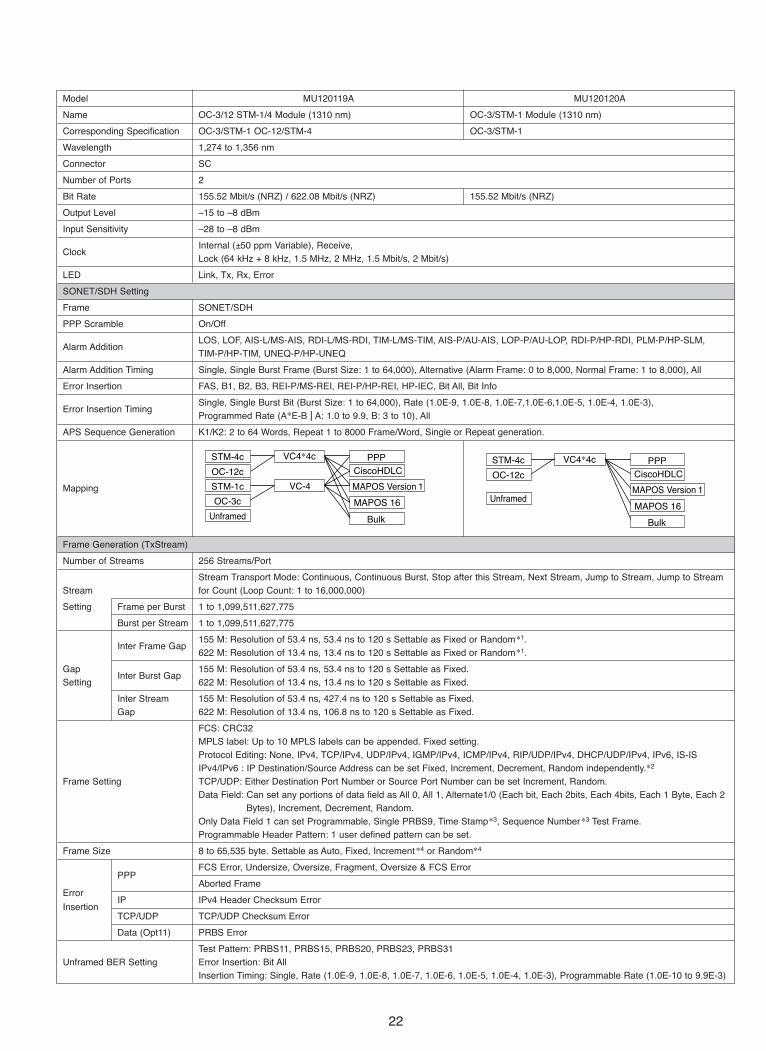
Model MU120119A MU120120A
Name OC-3/12 STM-1/4 Module (1310 nm) OC-3/STM-1 Module (1310 nm)
Corresponding Specification OC-3/STM-1 OC-12/STM-4 OC-3/STM-1
Wavelength 1,274 to 1,356 nm
Connector SC
Number of Ports 2
Bit Rate 155.52 Mbit/s (NRZ) / 622.08 Mbit/s (NRZ) 155.52 Mbit/s (NRZ)
Output Level –15 to –8 dBm
Input Sensitivity –28 to –8 dBm
ClockInternal (±50 ppm Variable), Receive,Lock (64 kHz + 8 kHz, 1.5 MHz, 2 MHz, 1.5 Mbit/s, 2 Mbit/s)
LED Link, Tx, Rx, Error
SONET/SDH Setting
Frame SONET/SDH
PPP Scramble On/Off
Alarm AdditionLOS, LOF, AIS-L/MS-AIS, RDI-L/MS-RDI, TIM-L/MS-TIM, AIS-P/AU-AIS, LOP-P/AU-LOP, RDI-P/HP-RDI, PLM-P/HP-SLM, TIM-P/HP-TIM, UNEQ-P/HP-UNEQ
Alarm Addition Timing Single, Single Burst Frame (Burst Size: 1 to 64,000), Alternative (Alarm Frame: 0 to 8,000, Normal Frame: 1 to 8,000), All
Error Insertion FAS, B1, B2, B3, REI-P/MS-REI, REI-P/HP-REI, HP-IEC, Bit All, Bit Info
Error Insertion TimingSingle, Single Burst Bit (Burst Size: 1 to 64,000), Rate (1.0E-9, 1.0E-8, 1.0E-7,1.0E-6,1.0E-5, 1.0E-4, 1.0E-3),Programmed Rate (A∗E-B I A: 1.0 to 9.9, B: 3 to 10), All
APS Sequence Generation K1/K2: 2 to 64 Words, Repeat 1 to 8000 Frame/Word, Single or Repeat generation.
Mapping
Frame Generation (TxStream)
Number of Streams 256 Streams/Port
Stream Transport Mode: Continuous, Continuous Burst, Stop after this Stream, Next Stream, Jump to Stream, Jump to Stream Stream for Count (Loop Count: 1 to 16,000,000)
Setting Frame per Burst 1 to 1,099,511,627,775
Burst per Stream 1 to 1,099,511,627,775
Inter Frame Gap155 M: Resolution of 53.4 ns, 53.4 ns to 120 s Settable as Fixed or Random∗1.622 M: Resolution of 13.4 ns, 13.4 ns to 120 s Settable as Fixed or Random∗1.
Gap Inter Burst Gap
155 M: Resolution of 53.4 ns, 53.4 ns to 120 s Settable as Fixed.Setting 622 M: Resolution of 13.4 ns, 13.4 ns to 120 s Settable as Fixed.
Inter Stream 155 M: Resolution of 53.4 ns, 427.4 ns to 120 s Settable as Fixed.Gap 622 M: Resolution of 13.4 ns, 106.8 ns to 120 s Settable as Fixed.
FCS: CRC32MPLS label: Up to 10 MPLS labels can be appended. Fixed setting.Protocol Editing: None, IPv4, TCP/IPv4, UDP/IPv4, IGMP/IPv4, ICMP/IPv4, RIP/UDP/IPv4, DHCP/UDP/IPv4, IPv6, IS-ISIPv4/IPv6 : IP Destination/Source Address can be set Fixed, Increment, Decrement, Random independently.∗2
Frame Setting TCP/UDP: Either Destination Port Number or Source Port Number can be set Increment, Random.Data Field: Can set any portions of data field as All 0, All 1, Alternate1/0 (Each bit, Each 2bits, Each 4bits, Each 1 Byte, Each 2
Bytes), Increment, Decrement, Random.Only Data Field 1 can set Programmable, Single PRBS9, Time Stamp∗3, Sequence Number∗3 Test Frame.Programmable Header Pattern: 1 user defined pattern can be set.
Frame Size 8 to 65,535 byte. Settable as Auto, Fixed, Increment∗4 or Random∗4
PPPFCS Error, Undersize, Oversize, Fragment, Oversize & FCS Error
Error Aborted Frame
IP IPv4 Header Checksum ErrorInsertion
TCP/UDP TCP/UDP Checksum Error
Data (Opt11) PRBS Error
Test Pattern: PRBS11, PRBS15, PRBS20, PRBS23, PRBS31Unframed BER Setting Error Insertion: Bit All
Insertion Timing: Single, Rate (1.0E-9, 1.0E-8, 1.0E-7, 1.0E-6, 1.0E-5, 1.0E-4, 1.0E-3), Programmable Rate (1.0E-10 to 9.9E-3)
VC-4STM-1c
Unframed
CiscoHDLC
Bulk
MAPOS Version 1
MAPOS 16
STM-4c
OC-12c
OC-3c
PPP
Unframed
CiscoHDLC
Bulk
MAPOS Version 1
MAPOS 16
STM-4c
OC-12c
PPP

23
Model MU120119A MU120120A
Measurement Function
SONET/SDH TestOH Monitor, Path Trace Monitor, K1/K2 Monitor, Pointer Monitor, APS Sequence Capture (Max 64 words), APS Switch Time Test, Performance Monitoring (ITU-T G.826)
NDF Count/Rate, +PJC Count/Rate, –PJC Count/Rate, Consecutive Count/Rate, PPM, HP-IEC Count/Rate, REI-P/HP-REI Count/Rate, B3 Count/Rate, UNEQ-P/HP-UNEQ Count/Second, PLM-P/HP-SLM Count/Second, RDI-P/HP-RDI
SONET/SDH Count/Second, LOP-P/AU-LOP Count/Second, AIS-P/AU-AIS Count/Second, REI-L/MS-REI Count/Second, B2 Count/Rate, B1 Count/Rate, RDI-L/MS-RDI Count/Second, AIS-L/MS-AIS Count/Second, OOF Count/Second, LOF Count/Second, Bit Info. Count/Rate∗5, Pattern Sync. Loss Count/Second∗5
Transmitted/Received Frame Count, Transmitted/Received Frame Rate, Transmitted/Received Bit Count, Transmitted/Received
PPPBit Rate, Transmitted/Received Byte Count, Transmitted/Received Rate, FCS Error, Undersize, Fragment, Oversize, Oversize & FCS Error
Transmitted Bytes After Stuffing, Received Bytes Before Destuffing, Aborted Frame
CounterIPv4
Transmitted/Received IPv4 Packet Count, Transmitted/Received IPv4 Packet Rate, Transmitted/Received Ping Request, Transmitted/Received Ping Reply, IP Header Checksum Error
TCP/UDPReceived TCP Packet Count, Received TCP Packet Rate, Received UDP Packet Count, Received UDP Packet Rate,TCP Checksum Error∗6, UDP Checksum Error∗6
DataCapture Trigger, Capture Filter, User Defined 1 Count/Rate, User Defined 2 Count/Rate, QoS 0 to 7 Frame Count/RateQoS Counter Setting: The target of QoS is IPv4 (ToS).
Packet BER Test Transmitted/Received Test Frame Count, Sequence Error, Received PRBS Error Frame Count/Rate, Received PRBS Error Bit (Opt11) Count/Rate
Unframed BER Bit Error Count/Rate, Pattern Sync. Loss Count/Second
Test
LatencyWhen Test Frames are received, the latency is indicated. The result includes 1s sampling value, max, min, avg. and number of samples.
Frame Arrival Time 32 counters make the result. Resolution : 1 μs, 10 μs, 100 μs, 1 ms, 10 ms, 100 ms, 1 s.
Capture Buffer 256 MByte/Port
At following conditions for each port, Capture Filter/Trigger condition settings:Capture Filter/
Condition: Destination IP Address, Source IP Address, 32-bit pattern 1, 32-bit pattern 2, ErrorTrigger
Only capture trigger can be set following: Traffic Over, Latency Over, External Trigger, Manual Trigger
CaptureEthernet (Type II, IEEE802.3, Mac Control), VLAN, MPLS, LLC, LACP, BPDU (STP, RST, MST), ARP, IP, IPv6 (include Extended
Decode ProtocolHeader), IPX, OSINL, IS-IS, IGMP (include IGAP), ICMP, ICMPv6 (include NDP, MLD, MLDA) TCP, UDP, OSPF, OSPFv3, DVMRP, LDP (CR-LDP), BGP4, RIP, DHCP, RSVP (RSVP-TE), BGP4+, PIM-SMv2, PPP (include LCP, IPCP, IPV6CP, OSINLCP, MPLSCP), CiscoHDLC, MAPOS, NSP, SSP, Test Frame
By Sniffer® Technologies (Opt04) or MX123002A Expert Analysis Module, the number of decode protocols can be increased upExtended
to 400.Decode Protocol
MD1230 Family includes Ethereal® Convert Function.
Protocol Emulation PPP (LCP, IPCP), ICMP, BGP-4, IGMP
Traffic MonitorTraffic Monitor can measure up to 64 streams in real-time.Target : IPv4 Address, Protocol Number (include Ether Type and IP Protocol Number)
Traffic Map Traffic Monitor can measure up to 64 streams in real-time. Target: IPv4 Address
Service Disruption Time Time of frame disruption.
Supported by MU120119A-01 Optical Power Meter Supported by MU120120A-01 Optical Power MeterMaximum Input Range: +10 dBm Maximum Input Range: + 10 dBm
Power MeterRange: –40 to +5 dBm Range: –40 to +5 dBmAccuracy: ±0.5 dB Accuracy: ±0.5 dB
RFC2544 Automatic TestFollowing 6 types of tests can be supported. (MD1230 Family supports continuous test [1] to [5].)[1] Throughput, [2] Latency, [3] Frame loss rate, [4] Back-to-back frames, [5] System recovery, [6] Reset
∗1: To select the Random setting for the inter-frame gap, the frame length must be 64 bytes or more.∗2: For IPv6, any Increment, Decrement, or Random setting can be specified for bit widths 1 to 32. Also, only either the destination or sender address can be
selected.∗3: When a sequence number or time stamp is used, the check sum field of the TCP/UDP packet contains an error code.∗4: Increment and Random settings can be specified for the frame size only when None is selected for the protocol.∗5: Measurement is enabled only when the Bulk setting is specified for mapping.∗6: The packets fragmented in the IP layer are counted as error packets.
MU120119A 155M/622M (1310 nm) MU120120A 155M (1310 nm)
24
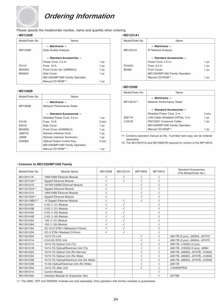
Please specify the model/order number, name and quantity when ordering.
Model/Order No. Name
— Mainframe —MD1230B Data Quality Analyzer
— Standard Accessories — Power Cord, 2.5 m: 1 pc
F0113 Fuse, 15 A: 1 pcB0329G Front Cover (for 3/4MW4U): 1 pcB0500A Side Cover: 1 pc
MD1230/MP1590 Family OperationManual CD-ROM∗1 : 1 pc
• MD1230B
Model/Order No. Name
— Mainframe —MD1231A1 IP Network Analyzer
— Standard Accessories — Power Cord, 2.5 m: 1 pc
F0100A Fuse, 6.3 A: 1 pcB0489 Front Cover: 1 pc
MD1230/MP1590 Family OperationManual CD-ROM∗1 : 1 pc
• MD1231A1
Model/Order No. Name
— Mainframe —MP1590B Network Performance Tester
— Standard Accessories — Shielded Power Cord, 2.6 m: 1 pc
F0105 Fuse, 10 A: 2 pcs E0010 Side Cover: 1 pcB0329G Front Cover (3/4MW4U): 1 pcJ0907Q Remote Interlock Cord: 1 pcJ0908 Remote Interlock Terminator: 1 pcE0008A Optical Output Control Key: 2 pcs
MD1230/MP1590 Family OperationManual CD-ROM∗1 : 1 pc
• MD1590B Model/Order No. Name
— Mainframe —MP1591A∗2 Network Performance Tester
— Standard Accessories — Shielded Power Cord, 3 m: 2 pcs
Z0917A LAN Cable (Shielded CAT5e), 5 m: 1 pc J1221B RSC232C Crossover Cable: 1 pc
MD1230/MP1590 Family OperationManual CD-ROM∗1: 1 pc
• MD1230B
∗1: Contains operation manual as file. A printed hard copy can be orderedseparately.
∗2: The MU159101A and MX159001B required for control of the MP1591A.
Model/Order No. Module Name MD1230B MD1231A1 MP1590A MP1591AStandard Accessories (The Model/Order No.)
MU120111A 10M/100M Ethernet Module √ √ √ √
MU120112A∗1 Gigabit Ethernet Module √ √ √ √
MU120121A 10/100/1000M Ethernet Module √ √ √
MU120122A∗1 Gigabit Ethernet Module √ √ √
MU120131A 10M/100M Ethernet Module √ √ √
MU120132A∗1 Gigabit Ethernet Module √ √ √
MU120118B/C∗1 10 Gigabit Ethernet Module √ √ √ √
MU120103A 2.5G (1.31) Module √ √ √
MU120103B 2.5G (1.31) Module √ √ √
MU120104A 2.5G (1.55) Module √ √ √
MU120104B 2.5G (1.55) Module √ √ √
MU120105A 10G (1.31) Module √ √ √
MU120106A 10G (1.55) Module √ √ √
MU120119A OC-3/12 STM-1/4Module(1310nm) √ √ √
MU120120A OC-3 STM-1Module(1310nm) √ √ √
MU150100A 10/10.7G Unit √ √ J0617B (2 pcs), J0635A, J0747C
MU150101A 2.5/2.6G EOS Unit √ √ J0617B (2 pcs), J0635A, J0747C
MU150121A 10/10.7G Optical Unit (Tx) √ √ J0617B, J1003Q (2 pcs),
MU150121B 10/10.7G Optical/Electrical Unit (Tx) √ √ J0617B, J1003Q (2 pcs), J0994
MU150122A 10/10.7G Optical Unit (Rx Narrow) √ √ J0617B, J0635A, J0747B, J1003Q
MU150123A 10/10.7G Optical Unit (Rx Wide) √ √ J0617B, J0635A, J0747B, J1003Q
MU150123B 10/10.7G Optical/Electrical Unit (Rx Wide) √ √ J0617B, J0635A, J0747B, J1003Q
MU150124B 10.3G Optical/Electrical Unit (Rx Wide) √ √ J0617B
MU150125A 10/10.7G Jitter Unit √ √ J1003N/P/R/S
MU159101A Control Module √
MU159103A Interface Module for Expansion Slot √ J0775B
∗1: The GBIC, SFP and XENPAK modules are sold separately. Only operation with Anritsu modules is guaranteed.
• Common to MD1230/MP1590 Family
Ordering Information
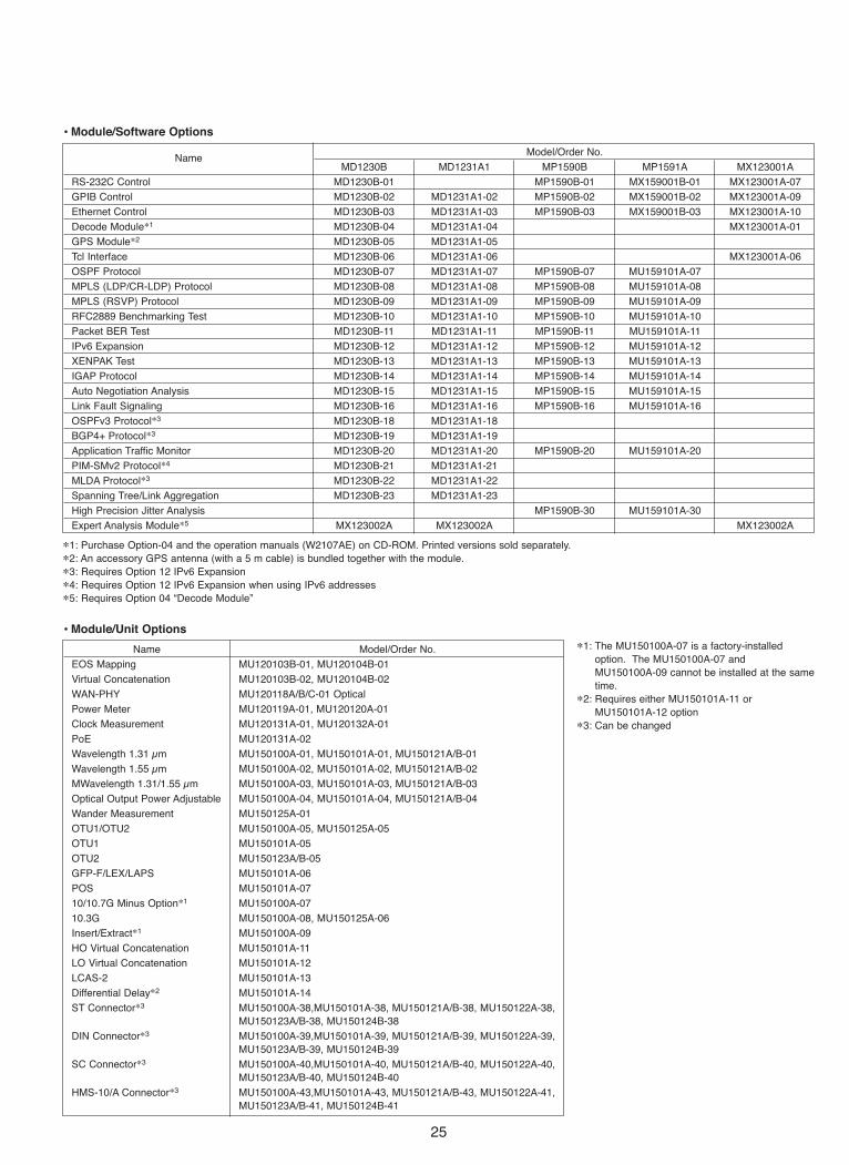
25
Model/Order No.Name
MD1230B MD1231A1 MP1590B MP1591A MX123001A
RS-232C Control MD1230B-01 MP1590B-01 MX159001B-01 MX123001A-07
GPIB Control MD1230B-02 MD1231A1-02 MP1590B-02 MX159001B-02 MX123001A-09
Ethernet Control MD1230B-03 MD1231A1-03 MP1590B-03 MX159001B-03 MX123001A-10
Decode Module∗1 MD1230B-04 MD1231A1-04 MX123001A-01
GPS Module∗2 MD1230B-05 MD1231A1-05
Tcl Interface MD1230B-06 MD1231A1-06 MX123001A-06
OSPF Protocol MD1230B-07 MD1231A1-07 MP1590B-07 MU159101A-07
MPLS (LDP/CR-LDP) Protocol MD1230B-08 MD1231A1-08 MP1590B-08 MU159101A-08
MPLS (RSVP) Protocol MD1230B-09 MD1231A1-09 MP1590B-09 MU159101A-09
RFC2889 Benchmarking Test MD1230B-10 MD1231A1-10 MP1590B-10 MU159101A-10
Packet BER Test MD1230B-11 MD1231A1-11 MP1590B-11 MU159101A-11
IPv6 Expansion MD1230B-12 MD1231A1-12 MP1590B-12 MU159101A-12
XENPAK Test MD1230B-13 MD1231A1-13 MP1590B-13 MU159101A-13
IGAP Protocol MD1230B-14 MD1231A1-14 MP1590B-14 MU159101A-14
Auto Negotiation Analysis MD1230B-15 MD1231A1-15 MP1590B-15 MU159101A-15
Link Fault Signaling MD1230B-16 MD1231A1-16 MP1590B-16 MU159101A-16
OSPFv3 Protocol∗3 MD1230B-18 MD1231A1-18
BGP4+ Protocol∗3 MD1230B-19 MD1231A1-19
Application Traffic Monitor MD1230B-20 MD1231A1-20 MP1590B-20 MU159101A-20
PIM-SMv2 Protocol∗4 MD1230B-21 MD1231A1-21
MLDA Protocol∗3 MD1230B-22 MD1231A1-22
Spanning Tree/Link Aggregation MD1230B-23 MD1231A1-23
High Precision Jitter Analysis MP1590B-30 MU159101A-30
Expert Analysis Module∗5 MX123002A MX123002A MX123002A
• Module/Software Options
∗1: Purchase Option-04 and the operation manuals (W2107AE) on CD-ROM. Printed versions sold separately.∗2: An accessory GPS antenna (with a 5 m cable) is bundled together with the module.∗3: Requires Option 12 IPv6 Expansion∗4: Requires Option 12 IPv6 Expansion when using IPv6 addresses∗5: Requires Option 04 “Decode Module”
Name Model/Order No.
EOS Mapping MU120103B-01, MU120104B-01
Virtual Concatenation MU120103B-02, MU120104B-02
WAN-PHY MU120118A/B/C-01 Optical
Power Meter MU120119A-01, MU120120A-01
Clock Measurement MU120131A-01, MU120132A-01
PoE MU120131A-02
Wavelength 1.31 μm MU150100A-01, MU150101A-01, MU150121A/B-01
Wavelength 1.55 μm MU150100A-02, MU150101A-02, MU150121A/B-02
MWavelength 1.31/1.55 μm MU150100A-03, MU150101A-03, MU150121A/B-03
Optical Output Power Adjustable MU150100A-04, MU150101A-04, MU150121A/B-04
Wander Measurement MU150125A-01
OTU1/OTU2 MU150100A-05, MU150125A-05
OTU1 MU150101A-05
OTU2 MU150123A/B-05
GFP-F/LEX/LAPS MU150101A-06
POS MU150101A-07
10/10.7G Minus Option∗1 MU150100A-07
10.3G MU150100A-08, MU150125A-06
Insert/Extract∗1 MU150100A-09
HO Virtual Concatenation MU150101A-11
LO Virtual Concatenation MU150101A-12
LCAS-2 MU150101A-13
Differential Delay∗2 MU150101A-14
ST Connector∗3 MU150100A-38,MU150101A-38, MU150121A/B-38, MU150122A-38,MU150123A/B-38, MU150124B-38
DIN Connector∗3 MU150100A-39,MU150101A-39, MU150121A/B-39, MU150122A-39,MU150123A/B-39, MU150124B-39
SC Connector∗3 MU150100A-40,MU150101A-40, MU150121A/B-40, MU150122A-40,MU150123A/B-40, MU150124B-40
HMS-10/A Connector∗3 MU150100A-43,MU150101A-43, MU150121A/B-43, MU150122A-41,MU150123A/B-41, MU150124B-41
∗1: The MU150100A-07 is a factory-installedoption. The MU150100A-07 and MU150100A-09 cannot be installed at the sametime.
∗2: Requires either MU150101A-11 orMU150101A-12 option
∗3: Can be changed
• Module/Unit Options

26
Name Model/Order No.
Data Quality Analyzer Control Software∗1 MX123001AData Quality Analyzer Control Software (5 licenses) MX123001A-05Data Quality Analyzer Control Software (8 licenses) MX123001A-08Remote Control Software for MD1230A-04∗2 MX123001A-01Remote Control Software for MD1230A-04 (5 licenses) MX123001A-15Remote Control Software for MD1230A-04 (8 licenses) MX123001A-18Remote Control Software for MX123002A∗3 MX123003ARemote Control Software for MX123002A (5 licenses) MX123003A-05Remote Control Software for MX123002A (8 licenses) MX123003A-08Network Performance Tester Control Software∗1 MX159001ANetwork Performance Tester Control Software (5 licenses) MX159001A-05Network Performance Tester Control Software (8 licenses) MX159001A-08
• Software
∗1: Ethernet control options (Option-03) are not required.∗2: One of the decode module options (Option 04) is required for
MX123001A Data Quality Analyzer Control Software and for cabinet control.
∗3: One of the decode module options (Option 04) and MX123002AMD1230A Expert Analysis Module are required for cabinet control.Also,MX123001A Data Quality Analyzer Control Software and MX123001A-01Option-04 Remote Control Software must be installed on the PC wherethis software is installed.
Name Model/Order No.
10GbE Slot Expansion for Bank A MP1591A-5010GbE Slot Expansion for Bank B MP1591A-51
• Other
Name Model/Order No.
2 Years Extended Warranty Service Option-ES2103 Years Extended Warranty Service Option-ES3105 Years Extended Warranty Service Option-ES510
• Maintenance Service
Name Model/Order No.
Annual Software Upgrade Service MD1230B-40, MP1590B-40, MP1591A-40
• Software Upgrade Service
∗ : Supports for only the MD1230 Family modules. Option-40 is providedfree for the first year after purchase. It is required to receive softwareupgrade service starting with the second year after purchase.
∗ : These options extend the 1-year guarantee at purchase.
∗7: B0336 Carrying case ∗8: B0533 Carrying case ∗9: B0448 Soft case ∗10: B0510 Soft case

27
Model/Order No. Name
G0105A GBIC SX 850 nm∗1
G0106A GBIC LX 1310 nm∗1
G0107A GBIC LH 1310 nm∗1
G0108A GBIC ZX 1550 nm∗1
G0124A GBIC T (1000BASE-T)∗1
G0136 SFP SX 850 nm∗2
G0137 SFP LX 1310 nm∗2
G0138 SFP LE 1310 nm∗2
G0139 SFP LR 1550 nm∗2
G0132 XENPAK (10GBASE-SR)∗3
G0126A XENPAK (10GBASE-LR)∗3
G0131 XENPAK (10GBASE-ER)∗3
G0150A XENPAK (10GBASE-LW)∗3
J0796A ST Connector (replaceable, with protective caps, 1 set)J0796B DIN Connector (replaceable, with protective caps,1 set)J0796C SC Connector (replaceable, with protective caps, 1 set)J0796D HMS-10/A Connector (replaceable, with protective caps, 1 set)J0796E FC Connector (replaceable, with protective caps, 1 set)J0617B Replaceable Optical Connector (FC-PC)J0747B Fixed Optical Attenuator (10 dB, FC connector)J0747C Fixed Optical Attenuator (15 dB, FC connector)J0747D Fixed Optical Attenuator (20 dB, FC connector)J1049A Fixed Optical Attenuator (SC, 5 dB)J1049B Fixed Optical Attenuator (SC, 10 dB)J1049C Fixed Optical Attenuator (SC, 15 dB)MZ1221A XAUI ExtenderMZ1222A XENPAK InterfaceJ1163A XAUI Cable, 0.5 mJ1164A MDIO Cable, 0.5 mJ0635A Optical Fiber Cable (SM, FC-SPC connector both ends), 1 mJ0635B Optical Fiber Cable (SM, FC-SPC connector both ends), 2 mJ0635C Optical Fiber Cable (SM, FC-SPC connector both ends), 3 mJ0660B Optical Fiber Cord (SM, SC-SC connector), 2 mJ0773B Optical Fiber Cord (GI, SC-SC connector), 2 mJ1200 Pmoptical Fiber cord (both-end SFC-SP connector), 0.5 mJ1119B Optical Fiber Cord (Duplex, MM), 2 mJ1271 Optical Fiber Cord (Duplex, SM, LC-LC connector), 2 mJ1272 Optical Fiber Cord (Duplex, SM, LC-SC connector), 2 mJ1273 Optical Fiber Cord (Duplex, GI, LC-LC connector), 2 mJ1274 Optical Fiber Cord (Duplex, GI, LC-SC connector), 2 mJ1003N Semi-rigid Cable (136.6 mm)J1003P Semi-rigid Cable (96 mm)J1003Q Semi-rigid Cable (75.6 mm)J1003R Semi-rigid Cable (55.3 mm)J1003S Semi-rigid Cable (56.5 mm)J0775B Coaxial Cable (BNC-P620 • 3C-2WS • BNC-P620, 75 Ω), 0.5 mJ0775D Coaxial Cable (BNC-P620 • 3C-2WS • BNC-P620, 75 Ω), 2 mJ0776D Coaxial Cable (BNC-P-3W • 3D-2W • BNC-P-3W, 50 Ω), 2 mJ0322B Coaxial Cable (11SMA • SUCOFLEX104 • 11SMA), 1 mJ1165A Coaxial Cable (27CP-P-1.5-BNC-P-1.5C-CR10), 0.5 mJ1166A Coaxial Cable (both ends, 27CP-P-1.5), 0.5 mJ0696A Coaxial Cable (AA-165-500) 0.5 m J1268 Semi-flexibility Coaxial Cable Z0478 Polarization Rotating Module (for MU150134A)J1173 6020180 Power DividerJ0845A Balanced Cable (BANTAM 3P/BANTAM 3P), 6 ftJ0162A Balanced Cable (Siemens 3P- Siemens 3P), 1 mJ0162B Balanced Cable (Siemens 3P- Siemens 3P), 2 mJ0008 GPIB Cable, 2 mJ1109B LAN Cable (CAT5, cross), 5 mJ1110B LAN Cable (CAT5, straight), 5 mJ1275 LAN Cable (CAT5E, straight), 1 mJ1275B LAN Cable (CAT5E, straight), 5 mJ1275C LAN Cable (CAT5E, cross), 1 mJ1275D LAN Cable (CAT5E, cross), 5 mZ0321A Keyboard (PS/2)Z0541A USB Mouse
Model/Order No. Name
B0336C Carrying Case (3/4MW4U, 350D)∗7
B0530 Carrying Case caster for B0336CB0533 Carrying Case (3/4MW4U, 350D)∗8
B0448 Soft Case∗9
B0510 Soft Case∗10
B0501B Blank Panel∗11
B571A Blank Panel∗12
B572A Blank Panel∗13
B573A Blank Panel∗14
B0590A Rack Flange∗15
Z0849A MD1230/MP1590 Family Manual CDW1927AE MD1230A/B Operation ManualW2096AE MD1231A/A1 Operation ManualW2420AE MP1590B Operation ManualW2735AE MP1591A Operation ManualW1928AE MX123001A Data Quality Analyzer Control Software
Operation ManualW2421AE MX159001B Operation SDH Edition ManualW2422AE MX159001B Operation SONET Edition ManualW1929AE MD1230A-01/02/03 Remote Control operation manualW2423AE MP1590B Remote Control Operation ManualW2107AE MD1230A-04/MX123001A-01 Operation ManualW2122AE MD1230A-06 Tcl Interface Operation ManualW2134AE Application Traffic Monitor Operation ManualW2108AE MX123002A/MX123003A Operation ManualW1931AE Ethernet Module Operation ManualW1932AE POS Module Operation ManualW2121AE MU120119A/MU120120A Operation ManualW2424AE MU150100A Specifications Operation ManualW2425AE MU150101A Specifications Operation ManualW2426AE MU150125A Specifications Operation ManualW2427AE MU150121/2/3/34A Specifications Operation ManualW2589AE MU150121B/123B Specifications Operation ManualW2590AE MU150124B Specifications Operation Manual
• Optional Accessories
∗1: The GBIC module is sold on a per-unit basis. MU120112A has two GBICinterface slots.
∗2: The SFP module is sold on a per-unit basis. MU120122A has two SFPinterface slots.And MU120132A has eight SFP interface slots.
∗3: The XENPAK module is sold on a per-unit basis. MU120118B has twoXENPAK interface slots. And MU120118C has one XENPAK interface slot.
∗4: Using the XAUI extender requires the MZ1222A XENPAK interface,J1163A XAUI cable, J1164A MDIO cable, and a separate external powersupply (5 V, 4 A), MZ1221A XAUI Extender, J1163A XAUI cable, 0.5 m,J1164A MDIO cable, 0.5 m, XENPAK, MZ1222A XENPAK Interface
∗5: MZ1222A supports 1.8 V fixed power supply regarding APS.∗6: This cable is required for time synchronization between MD1230 Family
cabinets. MD1230A/B and MP1591A use BNC connectors, andMD1231A1 uses an SMB connector. J0775D is required to connect BNCconnectors to each other. J1166A is required to connect SMB connectors to each other. J1165A is required to connect a BNC connector to an SMB connector.
∗7: Carrying case for MD1230B (See the photograph)∗8: Carrying case for MD1230B (See the photograph)∗9: Soft case for MD1230B (See the photograph)∗10: Soft case for MD1231A1 (See the photograph)∗11: Blank panel for module slot∗12: Blank panel for CPU slot of MP1591A∗13: Blank panel for DCS slot of MP1591A∗14: Blank panel for module slot of MP1591A∗15: Rack flange for MP1591A

Anritsu Corporation5-1-1 Onna, Atsugi-shi, Kanagawa, 243-8555 JapanPhone: +81-46-223-1111Fax: +81-46-296-1264
• U.S.A.Anritsu Company1155 East Collins Blvd., Richardson, TX 75081, U.S.A.Toll Free: 1-800-267-4878Phone: +1-972-644-1777Fax: +1-972-671-1877
• CanadaAnritsu Electronics Ltd.700 Silver Seven Road, Suite 120, Kanata, Ontario K2V 1C3, CanadaPhone: +1-613-591-2003 Fax: +1-613-591-1006
• Brazil Anritsu Eletrônica Ltda.Praca Amadeu Amaral, 27 - 1 Andar01327-010-Paraiso-São Paulo-BrazilPhone: +55-11-3283-2511Fax: +55-11-3288-6940
• U.K.Anritsu EMEA Ltd.200 Capability Green, Luton, Bedfordshire, LU1 3LU, U.K.Phone: +44-1582-433200 Fax: +44-1582-731303
• FranceAnritsu S.A.9 Avenue du Québec, Z.A. de Courtabœuf 91951 Les Ulis Cedex, France Phone: +33-1-60-92-15-50Fax: +33-1-64-46-10-65
• GermanyAnritsu GmbHNemetschek Haus, Konrad-Zuse-Platz 1 81829 München, Germany Phone: +49-89-442308-0 Fax: +49-89-442308-55
• ItalyAnritsu S.p.A.Via Elio Vittorini 129, 00144 Roma, ItalyPhone: +39-6-509-9711 Fax: +39-6-502-2425
• SwedenAnritsu ABBorgafjordsgatan 13, 164 40 KISTA, SwedenPhone: +46-8-534-707-00 Fax: +46-8-534-707-30
• FinlandAnritsu ABTeknobulevardi 3-5, FI-01530 VANTAA, FinlandPhone: +358-20-741-8100Fax: +358-20-741-8111
• DenmarkAnritsu A/SKirkebjerg Allé 90, DK-2605 Brøndby, DenmarkPhone: +45-72112200Fax: +45-72112210
• SpainAnritsu EMEA Ltd. Oficina de Representación en EspañaEdificio VeganovaAvda de la Vega, n˚ 1 (edf 8, pl 1, of 8)28108 ALCOBENDAS - Madrid, SpainPhone: +34-914905761Fax: +34-914905762
• United Arab EmiratesAnritsu EMEA Ltd.Dubai Liaison OfficeP O Box 500413 - Dubai Internet CityAl Thuraya Building, Tower 1, Suit 701, 7th FloorDubai, United Arab EmiratesPhone: +971-4-3670352Fax: +971-4-3688460
• SingaporeAnritsu Pte. Ltd.10, Hoe Chiang Road, #07-01/02, Keppel Towers,Singapore 089315 Phone: +65-6282-2400 Fax: +65-6282-2533
• P.R. China (Hong Kong)Anritsu Company Ltd.Suite 923, 9/F., Chinachem Golden Plaza, 77 Mody Road,Tsimshatsui East, Kowloon, Hong Kong, P.R. ChinaPhone: +852-2301-4980Fax: +852-2301-3545
• P.R. China (Beijing)Anritsu Company Ltd.Beijing Representative OfficeRoom 1515, Beijing Fortune Building, No. 5, Dong-San-Huan Bei Road, Chao-Yang District, Beijing 10004, P.R. ChinaPhone: +86-10-6590-9230Fax: +86-10-6590-9235
• KoreaAnritsu Corporation, Ltd.8F Hyunjuk Building, 832-41, Yeoksam Dong, Kangnam-ku, Seoul, 135-080, KoreaPhone: +82-2-553-6603Fax: +82-2-553-6604
• AustraliaAnritsu Pty. Ltd.Unit 21/270 Ferntree Gully Road, Notting Hill, Victoria 3168, AustraliaPhone: +61-3-9558-8177Fax: +61-3-9558-8255
• TaiwanAnritsu Company Inc.7F, No. 316, Sec. 1, Neihu Rd., Taipei 114, TaiwanPhone: +886-2-8751-1816Fax: +886-2-8751-1817
• IndiaAnritsu CorporationIndia Liaison OfficeUnit No. S-3, Second Floor, Esteem Red Cross Bhavan,No. 26, Race Course Road, Bangalore 560 001, IndiaPhone: +91-80-32944707Fax: +91-80-22356648
Specifications are subject to change without notice.
Catalog No. MD1230A/MP1590AFamily_Spec_IP-E-A-1-(1.00) Printed in Japan 2006-0Printed with environment-friendly vegetable soybean oil ink.
Printed on 100% Recycled Paper
Please Contact:
061121