Activity 2 – Defining Sea Traffic Management STM Architecture … · 2016-04-20 · STM...
35
MONALISA 2.0 — STM ARCHITECTURE FRAMEWORK 1 Activity 2 – Defining Sea Traffic Management STM Architecture Framework Document No: MONALISA 2.0 - D2.0.3 (includes also D2.2.2, D2.4.3, D2.5.3, D2.6.2)
Transcript of Activity 2 – Defining Sea Traffic Management STM Architecture … · 2016-04-20 · STM...
MONALISA 2.0 — STM ARCHITECTURE FRAMEWORK 1
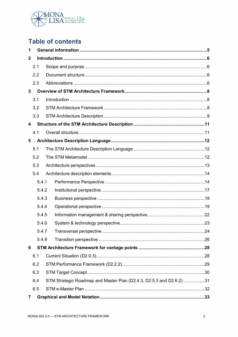
Activity 2 – Defining Sea Traffic Management
STM Architecture FrameworkDocument No: MONALISA 2.0 - D2.0.3 (includes also D2.2.2, D2.4.3, D2.5.3, D2.6.2)

MONALISA 2.0 — STM ARCHITECTURE FRAMEWORK 2
Document Status
The work with this report has been coordinated by:
Name Organisation
Mikael Olofsson Air Navigation Services of Sweden (LFV)
Beata Myhrer Air Navigation Services of Sweden (LFV)
Contribution and Approval by:
Organisation Approved by Date for approval
Carnival PLC, United Kingdom M.C. 03.12.2015
Chalmers University of Technology, Sweden M.H. 06.12.2015
Deutsches Zentrum fuer Luft- und Raumfahrt e.v., GermanyS.P. 10.11.2015
Fraunhofer-Gesellschaft Zurförderung der AngewandtenForschung e.v., Germany
O.J. 12.11.2015
Fundación Valenciaport, Spain J.A.G. 02.12.2015
Italian Ministry of Infrastructure and Transport/RServices/IB Software and Consulting, Italy
F.M 04.12.2015
Air Navigation Services of Sweden (LFV), Sweden M.B. 10.12.2015
Marsec –XL International Ltd, Malta G.F. 07.12.2015
Norwegian Coastal Administration, Norway S.T.F. 06.12.2015
SSPA Sweden AB, Sweden P.G. 03.12.2015
Swedish Maritime Administration, Sweden M.S. 06.12.2015
Viktoria Swedish ICT, Sweden M.L. 07.12.2015
Document History
Version Date Status
1.0 2015-12-10 Approved
TEN-T PROJECT NO: 2012-EU-21007-S
DISCLAIMER: THIS INFORMATION REFLECTS THE VIEW OF THE AUTHOR(S) AND THEEUROPEAN COMMISSION IS NOT LIABLE FOR ANY USE THAT MAY BE MADE OF THEINFORMATION CONTAINED THEREIN.
MONALISA 2.0 — STM ARCHITECTURE FRAMEWORK 3
Table of contents1 General information ......................................................................................................5
2 Introduction ...................................................................................................................6
2.1 Scope and purpose ..................................................................................................6
2.2 Document structure ..................................................................................................6
2.3 Abbreviations ...........................................................................................................6
3 Overview of STM Architecture Framework ..................................................................8
3.1 Introduction ..............................................................................................................8
3.2 STM Architecture Framework ...................................................................................8
3.3 STM Architecture Description ...................................................................................9
4 Structure of the STM Architecture Description .........................................................11
4.1 Overall structure .....................................................................................................11
5 Architecture Description Language ...........................................................................12
5.1 The STM Architecture Description Language .........................................................12
5.2 The STM Metamodel ..............................................................................................12
5.3 Architecture perspectives .......................................................................................13
5.4 Architecture description elements ...........................................................................14
5.4.1 Performance Perspective ................................................................................14
5.4.2 Institutional perspective ...................................................................................17
5.4.3 Business perspective ......................................................................................18
5.4.4 Operational perspective ..................................................................................19
5.4.5 Information management & sharing perspective ..............................................22
5.4.6 System & technology perspective....................................................................23
5.4.7 Transversal perspective ..................................................................................24
5.4.8 Transition perspective .....................................................................................26
6 STM Architecture Framework for vantage points .....................................................28
6.1 Current Situation (D2.0.3) .......................................................................................28
6.2 STM Performance Framework (D2.2.2) ..................................................................29
6.3 STM Target Concept ..............................................................................................30
6.4 STM Strategic Roadmap and Master Plan (D2.4.3, D2.5.3 and D2.6.2) .................31
6.5 STM e-Master Plan ................................................................................................32
7 Graphical and Model Notation ....................................................................................33

MONALISA 2.0 — STM ARCHITECTURE FRAMEWORK 4
8 Report generation .......................................................................................................33
8.1 Document reports ...................................................................................................33
8.2 Excel ......................................................................................................................33
9 Tools ............................................................................................................................33
10 References ...............................................................................................................33
Appendix A Activity 2 Deliverables ...............................................................................34
List of figures
Figure 1 STM Architecture Framework ...................................................................................8
Figure 2 STM Architecture Description ...................................................................................9
Figure 3 Overall structure .....................................................................................................11
Figure 4 Architecture perspectives and core elements .........................................................13
Figure 5 Metamodel for Performance perspective ................................................................14
Figure 6 Metamodel for Institutional perspective ...................................................................17
Figure 7 Metamodel for Business perspective ......................................................................18
Figure 8 Metamodel for Operational perspective ..................................................................19
Figure 9 Metamodel for Information management & sharing perspective .............................22
Figure 10 Metamodel for System & technology perspective .................................................23
Figure 11 Metamodel for Transversal perspective ................................................................24
Figure 12 Metamodel for Transition perspective ...................................................................26
Figure 13 Metamodel for Current Situation modelling ...........................................................28
Figure 14 Metamodel for STM Performance Framework modelling ......................................29
Figure 15 Metamodel for STM Target Concept modelling .....................................................30
Figure 16 Metamodel for STM Strategic Roadmap and Master Plan modelling ....................31
Figure 17 Metamodel for e-Master Plan modelling part ........................................................32
MONALISA 2.0 — STM ARCHITECTURE FRAMEWORK 5
1 General informationMONALISA 2.0 is a project with 39 private, public and academic partners from 10 differentcountries. Its overall objective is to strengthen efficiency, safety and environmental performance inmaritime transportation. Coordinated by the Swedish Maritime Administration, the project is co-financed by TEN-T under the Motorways of the Sea Programme and is part of the EU’s e-Maritimeinitiative. MONALISA 2.0 follows on from the MONALISA project (2010-EU-21109-S) and alsoincorporates results and experiences from the SESAR Programme (Single European Sky AirTraffic Management Research) in the aviation sector. MONALISA 2.0 is divided into fourActivities: Activity 1, STM Operations and Tools; Activity 2, STM Definition Phase; Activity 3, SaferShips; and Activity 4, Operational Safety.
This report is a deliverable from Activity 2 of the MONALISA 2.0 project. The objective of Activity 2is to outline a framework for Sea Traffic Management (STM), elaborate its target concept, anddevelop a plan for further development and deployment. Activity 2 is divided into 7 sub-activities:
· SA2.1 Current Situation Analysis describes today’s maritime transport industry,focusing on information sharing. It highlights its strengths, weaknesses, and currentdevelopment, as well its needs. The results of this analysis are presented in reportD2.1.1 STM The Current Situation.
· SA2.2 STM Performance Target Development is an analysis and elaboration of aperformance framework including: performance targets, key performance areas, visionand goals. Its results are presented in the report, D2.2.1 STM PerformanceFramework.
· SA2.3 STM Target Analysis develops the target concept(s) of Sea TrafficManagement based on the current situation analysis and performance targets. Theresults of this work are summarised in the report D2.3.1 STM - The Target Concept.
· SA2.4, 2.5 & 2.6 STM Strategic Roadmap and Master Plan Development and WorkProgramme for Development Phase is a combination of three sub-activities thattogether establish a shared vision of the overall transition sequence for implementingthe STM Target Concept. Results are described in report D2.4.2/D2.5.1/2.6.1 STMMaster Plan.
· SA2.7 Port CDM Demonstrator developed and demonstrated initial versions of someinformation sharing services used in the Port CDM concept. Results are presented inthe report D2.7.1 Port CDM Report.
This report describes the framework that the STM Architecture Description is based on.
MONALISA 2.0 — STM ARCHITECTURE FRAMEWORK 6
2 Introduction
2.1 Scope and purposeThe purpose of this document is to describe the framework that the STM Architecture Descriptionis based on.
The STM Architecture Framework serves both as a planning tool and as documentation of thebasis of the STM Architecture Description. The content in this document has been used for theelaboration of the STM Architecture Description and has also influenced the elaboration of theSTM Performance Framework (D2.2.1), the STM Target Concept (D2.3.1) and the STM MasterPlan (D2.4.2 and D2.5.1).
This document is primarily aimed at the reader who needs a detailed understanding of the STMArchitecture Description for upcoming architecting work and involved architects. The detailedcontent in this document has been elaborated and documented in an STM ArchitectureDescription repository with a model based approach.
2.2 Document structureThis document contains the following chapters.
1. Introduction (this chapter)2. Overview of STM Architecture Framework
Gives background information to the concept of architecture framework based on ISO42010
3. Structure of the STM Architecture DescriptionDescribes the structure of the STM Architecture Description reported in separatedeliverables
4. Architecture Description LanguageDescribes in detail the metamodel of the STM Architecture Description
5. STM Architecture Framework for vantage pointsDescribes the metamodel for each vantage point (as-is and to-be model)
6. Graphical and Model Notation7. Report Generation8. Tools
2.3 AbbreviationsName Description
ADL Architecture Description Language
e-Master Plan Electronic Master Plan
ICAO International Civil Aviation Organisation

MONALISA 2.0 — STM ARCHITECTURE FRAMEWORK 7
ISO International Standard Organisation
SESAR Single European Sky ATM Research
STM Sea Traffic Management
STM EA STM Enterprise Architecture
MONALISA 2.0 — STM ARCHITECTURE FRAMEWORK 8
3 Overview of STM Architecture Framework
3.1 IntroductionArchitecture frameworks and architecture description languages are two mechanisms that arewidely used in architecting (ref ISO 42010).
In the following sections, the STM Architecture Framework and the STM Architecture DescriptionLanguage and their relationships are described.
3.2 STM Architecture FrameworkAn architecture framework establishes a common practice for creating, interpreting, analysing andusing architecture descriptions within a particular domain of application or stakeholder community(ref ISO 42010).
The foundation of the STM Architecture Framework is inspired by ISO 42010. This internationalarchitecture framework standard includes conventions, principles and practices for the descriptionof architectures established within a specific domain of application and/or community ofstakeholders.
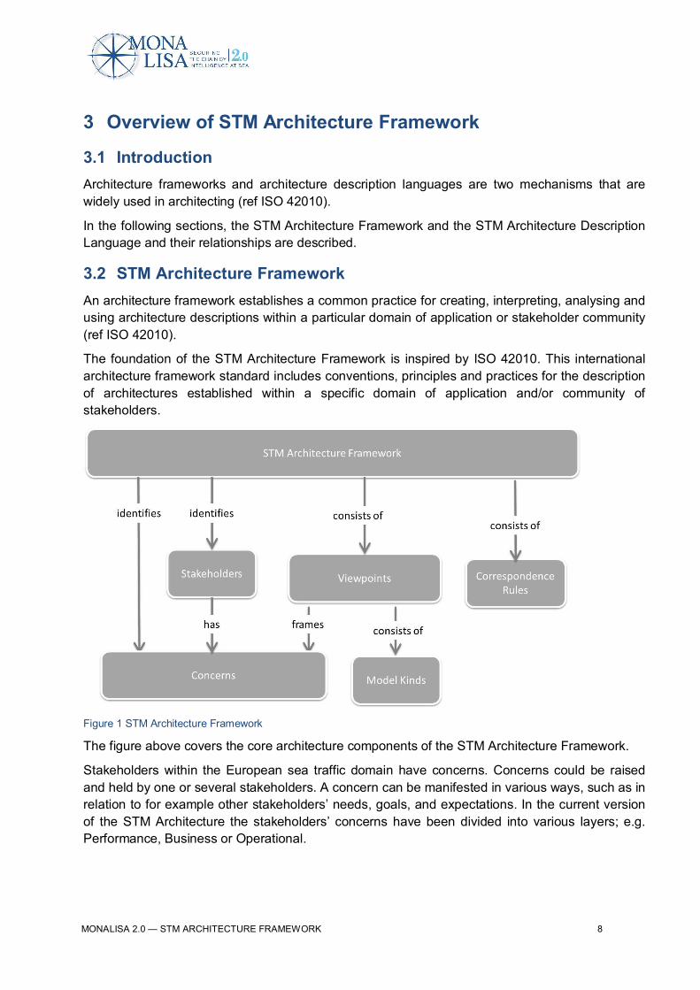
Figure 1 STM Architecture Framework
The figure above covers the core architecture components of the STM Architecture Framework.
Stakeholders within the European sea traffic domain have concerns. Concerns could be raisedand held by one or several stakeholders. A concern can be manifested in various ways, such as inrelation to for example other stakeholders’ needs, goals, and expectations. In the current versionof the STM Architecture the stakeholders’ concerns have been divided into various layers; e.g.Performance, Business or Operational.

MONALISA 2.0 — STM ARCHITECTURE FRAMEWORK 9
Viewpoints are used to frame one or more stakeholders’ concerns. Each viewpoint establishesconventions for construction, interpretation and analysis. The viewpoint conventions include forexample notations, model kinds and/or modelling methods.
Model kinds can for example be tables, excel sheets, maps, information models and processdiagrams. The current version of the STM Architecture has so far solely used UML notation and amap approach.
One specific kind of model in the STM Architecture Framework is the metamodel of thearchitecture description elements, see section 4.2. An architecture description element is anyconstruct in an architecture description. The correspondence rules; i.e. how the architecturedescription elements in the architecture are related to each other is governed by the underlyingmetamodel, see section 4.4 in this document. These relationships are used to express, and toenforce, the architecture relations such as for example composition, consistency, traceability anddependencies.
3.3 STM Architecture DescriptionAn architecture description shall identify the system-of-interest and include supplementaryinformation as determined by the project and/or organisation (ref ISO42010).
The STM Architecture Descriptions are work products (depicted in darker colour in Figure 2) usedto express the STM Architecture based on interested parties and stakeholders’ particularviewpoints. The figure below provides an overview of how the STM Architecture Description isrelated to the STM Architecture Framework.
Figure 2 STM Architecture Description
A view in a work product expresses (describes) the architecture in accordance with the viewpoint.Each view is governed by a defined viewpoint in the STM Architecture Framework: e.g. the STMPerformance Framework view is governed by the Performance layer.

MONALISA 2.0 — STM ARCHITECTURE FRAMEWORK 10
A view can consist of one or several kinds of models. In the current STM Architecture are modelsexpressed by using Unified Modelling Language (UML) notation. Some models kinds are basedon elaborated approaches; e.g. the Performance Framework inspired by ICAO and SESAR.
The correspondence between the architecture description elements in each view and relatedmodels are defined in the STM Metamodel, see section 4.4. The correspondence is determinedvia various kinds of relationships; e.g. “consists of”, generalisation-specialisation.
MONALISA 2.0 — STM ARCHITECTURE FRAMEWORK 11
4 Structure of the STM Architecture Description
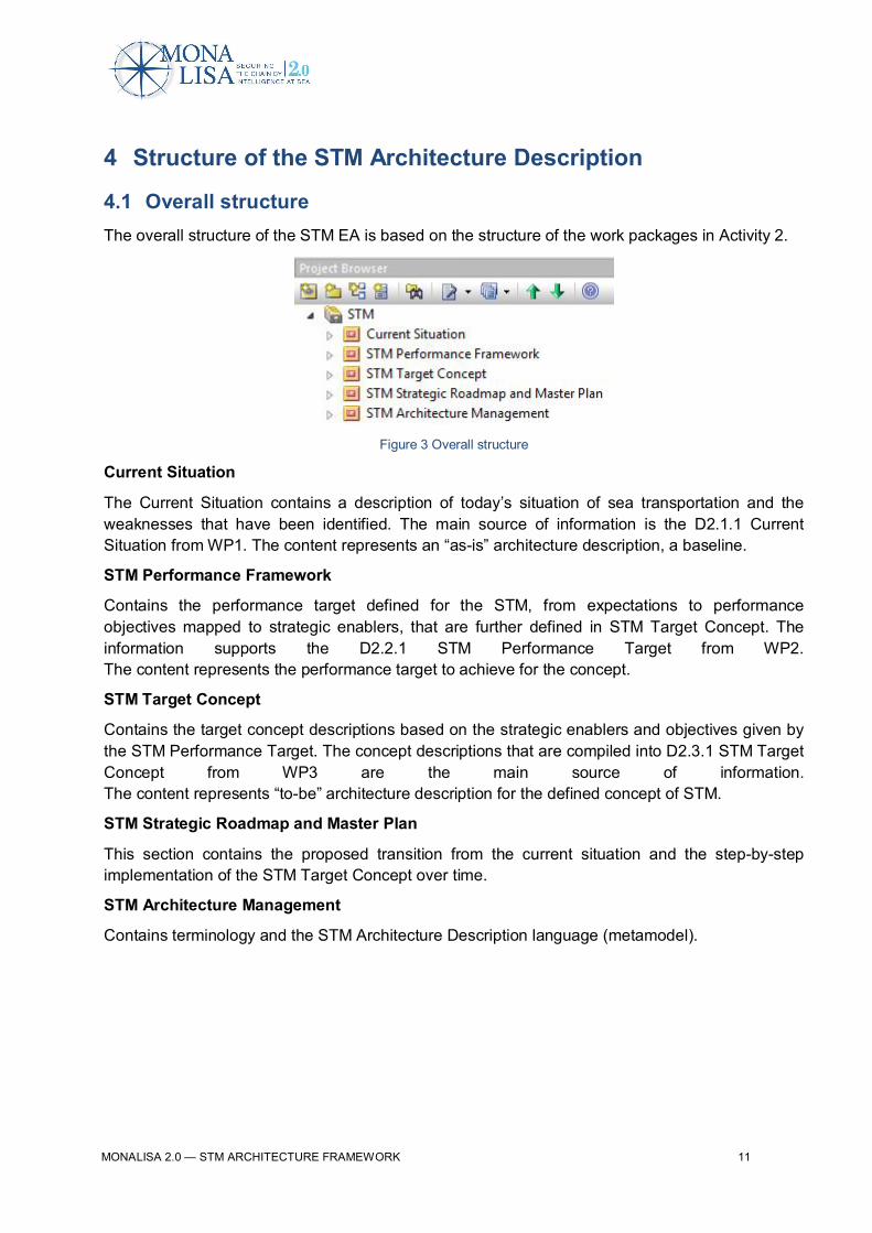
4.1 Overall structureThe overall structure of the STM EA is based on the structure of the work packages in Activity 2.
Figure 3 Overall structure
Current Situation
The Current Situation contains a description of today’s situation of sea transportation and theweaknesses that have been identified. The main source of information is the D2.1.1 CurrentSituation from WP1. The content represents an “as-is” architecture description, a baseline.
STM Performance Framework
Contains the performance target defined for the STM, from expectations to performanceobjectives mapped to strategic enablers, that are further defined in STM Target Concept. Theinformation supports the D2.2.1 STM Performance Target from WP2.The content represents the performance target to achieve for the concept.
STM Target Concept
Contains the target concept descriptions based on the strategic enablers and objectives given bythe STM Performance Target. The concept descriptions that are compiled into D2.3.1 STM TargetConcept from WP3 are the main source of information.The content represents “to-be” architecture description for the defined concept of STM.
STM Strategic Roadmap and Master Plan
This section contains the proposed transition from the current situation and the step-by-stepimplementation of the STM Target Concept over time.
STM Architecture Management
Contains terminology and the STM Architecture Description language (metamodel).
MONALISA 2.0 — STM ARCHITECTURE FRAMEWORK 12
5 Architecture Description Language
5.1 The STM Architecture Description LanguageAn architecture description language (ADL) is any form of expression used in architecturedescriptions, ref ISO 42010. According to ISO 42010 an architecture description language shallspecify;
· the identification of one or more concerns to be expressed by the ADL;· the identification of one or more stakeholders having those concerns;· the model types implemented by ADL which frame those concerns;· any architecture viewpoints; and· corresponding rules relating its model kinds.
The purpose of an STM Architecture Description Language is to define what architecturedescription elements are included and how they are related to each other. This will establish andguide the composition, consistency, traceability, dependency and constraints of the architecturecontent.
An architecture description element is any construct in an architecture description; e.g. everymodel kind, model, view, viewpoint is considered to be an architecture element. They are the mostprimitive constructs in architecture.
5.2 The STM MetamodelWhen viewpoints and model kinds have been defined, and their models have been populated,additional architecture elements will be introduced.
The STM metamodel is a specific model kind that describes the introduced specific STMarchitecture description elements and their relationships. These relationships are thecorrespondence rules for the architecture description elements that is used when populating theSTM architecture.
When populating the STM architecture with various information it will support the developmentand analysis of the coverage, gaps, overlaps, consistency and coherency of the materialdeveloped by the various tasks within MONALISA Activity 2.
In chapter 4.4 there is a detailed overview of the STM Metamodel and in the subsections thearchitecture descriptions elements are listed and described.
MONALISA 2.0 — STM ARCHITECTURE FRAMEWORK 13
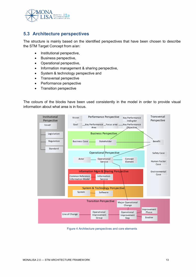
5.3 Architecture perspectivesThe structure is mainly based on the identified perspectives that have been chosen to describethe STM Target Concept from a/an:
· Institutional perspective,· Business perspective,· Operational perspective,· Information management & sharing perspective,· System & technology perspective and· Transversal perspective· Performance perspective· Transition perspective
The colours of the blocks have been used consistently in the model in order to provide visualinformation about what area is in focus.
Figure 4 Architecture perspectives and core elements
Business Perspective
Operational Perspective
TransversalPerspective
Performance Perspective
Transition Perspective
System & Technology Perspective
Information Mgm & Sharing Perspective
InstitutionalPerspective
Legislation
Regulation
Standard
Business Case
Vision
Stakeholder
Human FactorCase
Key PerformanceArea
ConceptElement
Actor OperationalService
Issuer
Software
EnvironmentalCase
Safety Case
Common ReferenceInformation Model
Key PerformanceObjective
System
InformationService
Goal Focus area
Benefit
OperationalImprovement
Step Enabler
ImprovementPhase
Key PerformanceIndicator
OperationalImprovement
GroupLine of Change
Major OperationalChange
MONALISA 2.0 — STM ARCHITECTURE FRAMEWORK 14
5.4 Architecture description elementsThis section provides and explanation for each architecture description element used in the STMArchitecture Description.
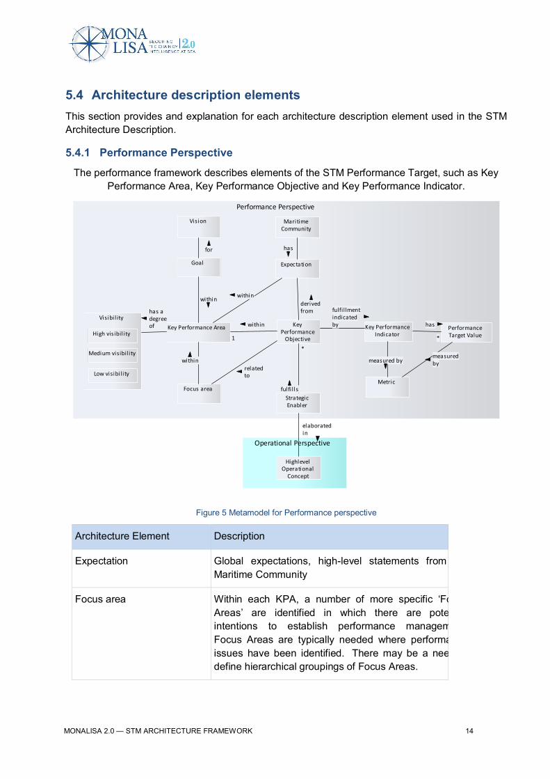
5.4.1 Performance Perspective
The performance framework describes elements of the STM Performance Target, such as KeyPerformance Area, Key Performance Objective and Key Performance Indicator.
Figure 5 Metamodel for Performance perspective
Architecture Element Description
Expectation Global expectations, high-level statements from theMaritime Community
Focus area Within each KPA, a number of more specific ‘FocusAreas’ are identified in which there are potentialintentions to establish performance management.Focus Areas are typically needed where performanceissues have been identified. There may be a need todefine hierarchical groupings of Focus Areas.
Operational Perspective
Performance Perspective
KeyPerformance
Objective
Key PerformanceIndicator
PerformanceTarget Value
Key Performance Area
Focus areaMetric
StrategicEnabler
MaritimeCommunity
Expectation
Visibi l ity
High vis ibil i ty
Medium visibil i ty
Low visibi l i ty
HighlevelOperational
Concept
Goal
Vision
has adegreeof within
1
relatedto
derivedfrom
has
*
fulfil lmentindicatedby
measuredby
within
within
fulfi l ls
*
elaboratedin
has
within
for
measured by
MONALISA 2.0 — STM ARCHITECTURE FRAMEWORK 15
Architecture Element Description
Goal A specified and measurable goal quantifying the vision.
High visibility High visibility means that the KPA is highly important tocommunicate to decision makers and the world outsideof MONALISA.
Effects are of a political nature and are even visible tothose who are not users of the STM Transport System.(Societal Outcome)
Key Performance Area Key Performance Areas are a way of categorisingperformance subjects related to high-level ambitionsand expectations.
Key Performance Indicator Current/past performance, expected future performance(estimated as part of forecasting and performancemodelling), as well as actual progress in achievingperformance objectives is quantitatively expressed bymeans of indicators (sometimes called KeyPerformance Indicators, or KPIs). To be relevant,indicators need to correctly express the intention of theassociated performance objective. Since indicatorssupport objectives, they should not be defined withouthaving a specific performance objective in mind.Indicators are not often directly measured. They arecalculated from supporting metrics according to clearlydefined formulas, e.g. cost-per-flight-indicator = Sum(cost)/Sum (flights). Performance measurement istherefore done through the collection of data for thesupporting metrics.
Key Performance Objective Performance objectives define, in a qualitative butfocused way, a desired trend from today’s performance(e.g. improvement).
Low visibility Low visibility means less/not visible outside of theMONALISA context but still as important as the otherKPAs. Often the medium and low visible KPAsunderpins the highly visible KPAs.
These are not of direct interest to sea space usercustomers and the KPAs play their roles mostly at thevoyage planning stage. (Performance Enablers)

MONALISA 2.0 — STM ARCHITECTURE FRAMEWORK 16
Architecture Element Description
Maritime Community The aggregation of organisations, associations,(agencies) or others that may participate, collaborateand cooperate in the planning, development, use,regulation, operation and maintenance related to SeaTraffic Management.
Medium visibility Medium visibility means less visible outside MONALISAbut still as important as the other KPAs. Often themedium and low visible KPAs underpins the highlyvisible KPAs.
Visibility of the effects stops generally at the level of PortAuthorities, Terminal Operators, sea space users andsea space user customers (e.g. passengers).(Operational Performance)
Metric Used to calculate the values of the performanceindicators. For example cost-per-voyage-indicator =Sum (cost)/Sum (Voyages).
Performance Target Value Performance targets are closely associated withperformance indicators: they represent the values ofperformance indicators that need to be reached orexceeded to consider a performance objective as beingfully achieved.
Strategic Enabler A strategic enabler in this context is an essential enablerto meet the performance objectives. Enabler can be ofdifferent types e.g. institutional, procedural, technical,and human.
Visibility The visibility of the KPA relates to the communicationwith the stakeholders. The decision criteria for groupingare based on the "highest" degree of visibility of theKPA outcome and impact, rather than on how theperformance is achieved.
Vision A visionary statement setting a target to strive for and toachieve an interoperable global STM for all users duringall operational phases, that meet agreed levels ofsafety, provides optimum economic operations, isenvironmentally sustainable and meets national securequirements.

MONALISA 2.0 — STM ARCHITECTURE FRAMEWORK 17
5.4.2 Institutional perspective
The Institutional perspective focuses on the legislative, regulatory and standardisation in seatransportation.
Figure 6 Metamodel for Institutional perspective
Architecture Element Description
Issuer An organisation or associations that issues e.g. legislation,regulation, directive, standard etc.
Legislation A law, or set of laws made by a government.
Regulation An official rule or law that says how something should be done
Standard Document, established by consensus and approved by arecognized body, that provides, for common and repeated use,rules guidelines or characteristics for activities or their results,aimed at the achievement of the optimum degree of order ingiven context.
Institutional Perspective
Legislation Regulation Standard
Issuer

MONALISA 2.0 — STM ARCHITECTURE FRAMEWORK 18
5.4.3 Business perspective
The Business Perspective focuses on the business aspects of the sea transport sector, businessdescriptions, stakeholders, benefits and business cases.
Figure 7 Metamodel for Business perspective
Architecture Element Description
Actual Organisation An actual (real) organisation.
Business BenefitA business benefit from the target concept of Sea TrafficManagement related to a KPA (primarily cost/economy,safety and environment).
Business Case
Business cases are created to help decision-makers ensurethat:
- the proposed initiative will have value and relative prioritycompared to alternative initiatives based on the objectivesand expected benefits laid out in the business case
-the performance indicators found in the business case areidentified to be used for proactive realisation of the businessand behavioural change.
Business Description Textual description of the business performed
Business ModelA business model describes the rationale of how anorganization creates, delivers, and captures value, ineconomic, social, cultural or other contexts.
Organisation type Abstract (generic) type of organisation.
Stakeholder An organisation, association or community that have a strong
Business Perspective
Business Case
Stakeholder
BusinessModel
BusinessDescription
Business Benefit
TransversalPerspective
Cost BenefitAnalysis
ActualOrganisation
Organisationtype
forpartof
describedin
expects
quantifies
for
MONALISA 2.0 — STM ARCHITECTURE FRAMEWORK 19
interest in (e.g. cost, safety, environment), or will be impactedby, Sea Traffic Management.
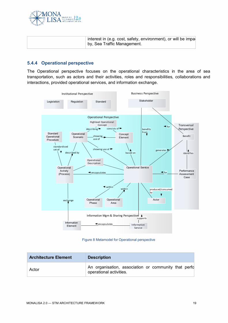
5.4.4 Operational perspective
The Operational perspective focuses on the operational characteristics in the area of seatransportation, such as actors and their activities, roles and responsibilities, collaborations andinteractions, provided operational services, and information exchange.
Figure 8 Metamodel for Operational perspective
Architecture Element Description
Actor An organisation, association or community that performsoperational activities.
TransversalPerspective
Information Mgm & Sharing Perspective
Operational Perspective
Business PerspectiveInstitutional Perspective
Legislation
OperationalArea
OperationalActivity
(Process)
Stakeholder
InformationElement
Regulation Standard
OperationalPhase
OperationalScenario
StandardOperationalProcedure
Operational Service
Actor
ConceptElement
PerformanceAssessment
Case
InformationService
Benefit
Highlevel OperationalConcept
OperationalDescription
within
based on
encapsulates
standardisedset of showing use of
describing
showinguse of
generates
benefitsfrom
exchange
described by identifies
consists offor
within
encapsulates
produced/consumedby
for
supports

MONALISA 2.0 — STM ARCHITECTURE FRAMEWORK 20
Concept Element
A concept element is a part of the concept that is essentialand characterizes the concept. The concept element is oftenrepresented by a term, which shall be defined. The conceptelement can also be further elaborated as an informationelement, process, service etc.
Geographical Area A defined sea area in which sea operations are conducted.The area may be static or temporarily in time.
High-level Operational Concept
A high-level description of the STM services necessary toaccommodate traffic at a given time horizon; a description ofthe anticipated level of performance required from, and theinteraction between, the STM services, as well as the objectthey affect, and a description of the information to beprovided to agents in the STM and how that information is tobe used for operational purposes. The operational concept isneither a description of the sea navigation infrastructure nora technical system description nor a detailed description ofhow a particular functionality or technology could be used.
Information Element Knowledge communicated or received concerning aparticular fact or circumstance.
Operational Activity (Process)
An activity, or sequence of activities, that produces anoperational value (processes and activities). Can bedecomposed to the level of detail that is required. Can beformalised into Standard Operational Procedure.
Operational Area An area of responsibility relevant for the operations of seatraffic.
Operational Benefit Operational benefit is value (time, cost, satisfaction and/orbusiness revenue) gained from capabilities/services in use.
Operational Characteristic A characteristic (attribute) describing an operationalenvironment for sea operation.
Operational Description Textual operational description of the concept.
Operational Environment Operational environment is the context within the businessand operation is performed within the sea traffic domain.
Operational PhaseA phase related to a (relative) timeframe within operationalactivities is performed (e.g. Planning phase, Executionphase).
Operational Role
An operational role is a role that an actor (as organizationalposition, technical system and/or organisation) canundertake, on behalf of an organisation/association and/orcommunity, performing operational activities. Compare with’position’ where actors hold a certain role (e.g. captain) with

MONALISA 2.0 — STM ARCHITECTURE FRAMEWORK 21
assigned expectations, responsibilities and mandates to act.
Operational Scenario A textual outline of expected or agreed sequence of seatraffic operations events.
Operational Service
A service that encapsulates an operational part independentof technical solution in order to deliver operational value.
An operational service can be further described by the set ofactors and operational activities that are encapsulated by theoperational service.
MONALISA 2.0 — STM ARCHITECTURE FRAMEWORK 22
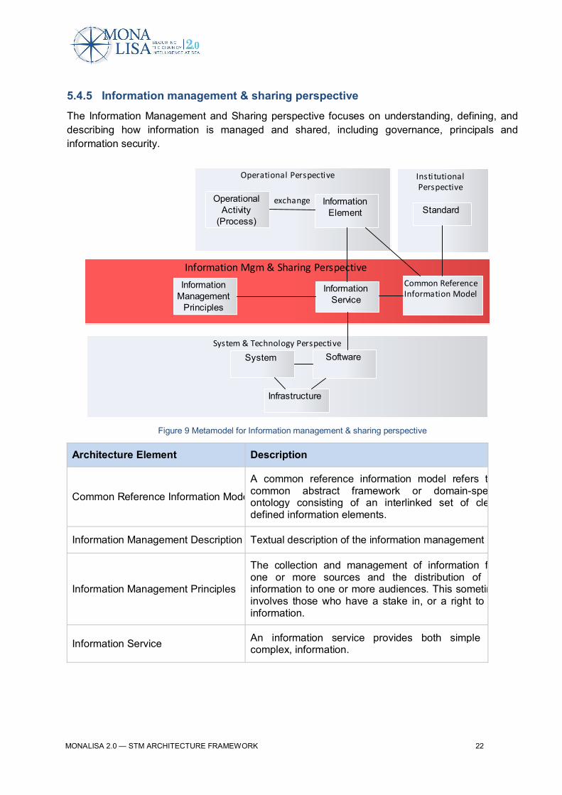
5.4.5 Information management & sharing perspective
The Information Management and Sharing perspective focuses on understanding, defining, anddescribing how information is managed and shared, including governance, principals andinformation security.
Figure 9 Metamodel for Information management & sharing perspective
Architecture Element Description
Common Reference Information Model
A common reference information model refers to acommon abstract framework or domain-specificontology consisting of an interlinked set of clearlydefined information elements.
Information Management Description Textual description of the information management
Information Management Principles
The collection and management of information fromone or more sources and the distribution of thatinformation to one or more audiences. This sometimesinvolves those who have a stake in, or a right to thatinformation.
Information Service An information service provides both simple andcomplex, information.
System & Technology Perspective
InstitutionalPerspective
Operational Perspective
Information Mgm & Sharing Perspective
StandardOperational
Activity(Process)
InformationElement
System
InformationManagement
Principles
InformationService
Software
Infrastructure
Common ReferenceInformation Model
exchange
MONALISA 2.0 — STM ARCHITECTURE FRAMEWORK 23
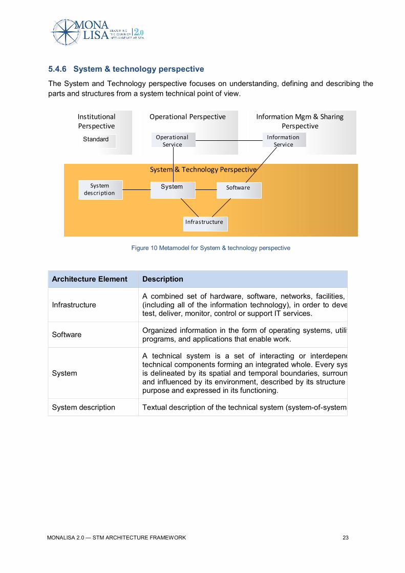
5.4.6 System & technology perspective
The System and Technology perspective focuses on understanding, defining and describing theparts and structures from a system technical point of view.
Figure 10 Metamodel for System & technology perspective
Architecture Element Description
InfrastructureA combined set of hardware, software, networks, facilities, etc.(including all of the information technology), in order to develop,test, deliver, monitor, control or support IT services.
Software Organized information in the form of operating systems, utilities,programs, and applications that enable work.
System
A technical system is a set of interacting or interdependenttechnical components forming an integrated whole. Every systemis delineated by its spatial and temporal boundaries, surroundedand influenced by its environment, described by its structure andpurpose and expressed in its functioning.
System description Textual description of the technical system (system-of-systems)
InstitutionalPerspective
Operational Perspective
System & Technology Perspective
System
Standard
Software
Infrastructure
Information Mgm & SharingPerspective
InformationService
OperationalService
Systemdescription
MONALISA 2.0 — STM ARCHITECTURE FRAMEWORK 24
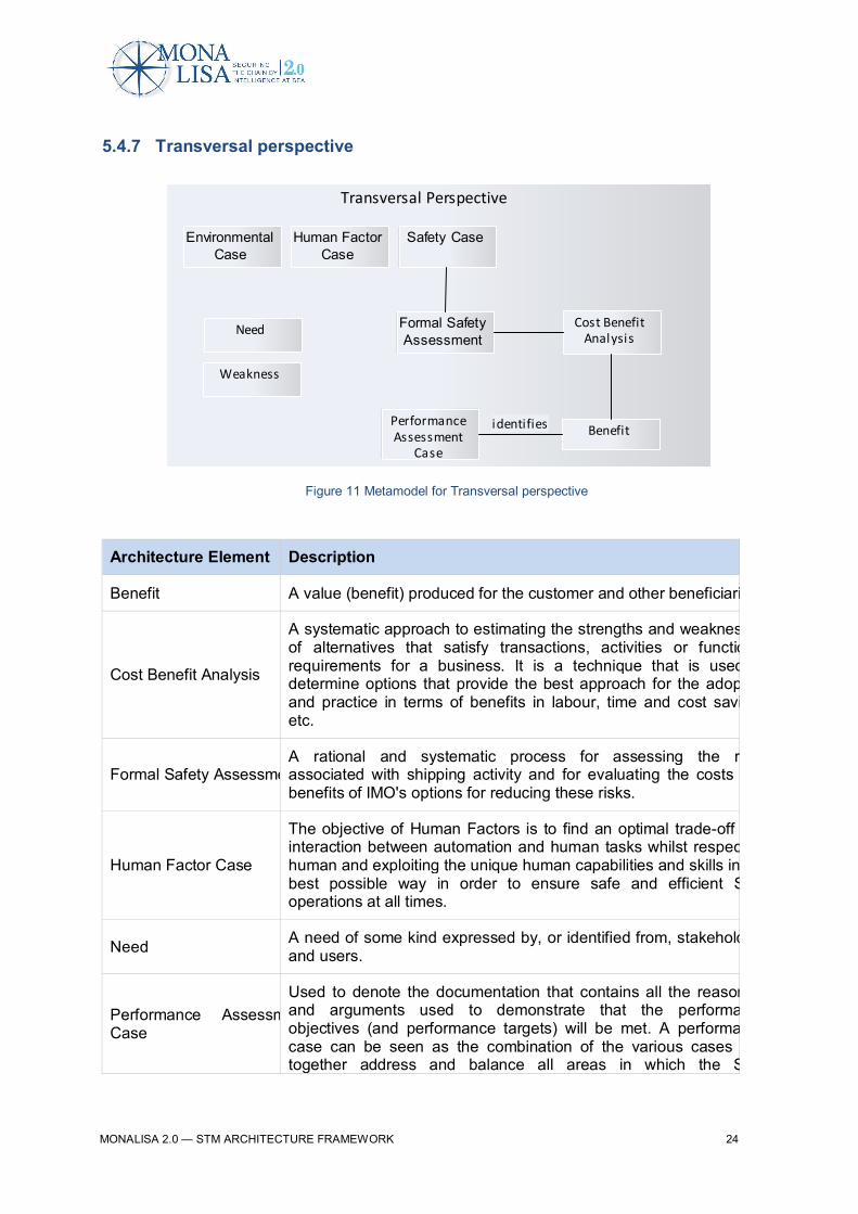
5.4.7 Transversal perspective
Figure 11 Metamodel for Transversal perspective
Architecture Element Description
Benefit A value (benefit) produced for the customer and other beneficiaries.
Cost Benefit Analysis
A systematic approach to estimating the strengths and weaknessesof alternatives that satisfy transactions, activities or functionalrequirements for a business. It is a technique that is used todetermine options that provide the best approach for the adoptionand practice in terms of benefits in labour, time and cost savingsetc.
Formal Safety AssessmentA rational and systematic process for assessing the risksassociated with shipping activity and for evaluating the costs andbenefits of IMO's options for reducing these risks.
Human Factor Case
The objective of Human Factors is to find an optimal trade-off andinteraction between automation and human tasks whilst respectinghuman and exploiting the unique human capabilities and skills in thebest possible way in order to ensure safe and efficient STMoperations at all times.
Need A need of some kind expressed by, or identified from, stakeholdersand users.
Performance AssessmentCase
Used to denote the documentation that contains all the reasoningand arguments used to demonstrate that the performanceobjectives (and performance targets) will be met. A performancecase can be seen as the combination of the various cases thattogether address and balance all areas in which the STM
Transversal Perspective
Human FactorCase
Formal SafetyAssessment
EnvironmentalCase
Safety Case
Benefit
Cost BenefitAnalysis
PerformanceAssessment
Case
Need
Weakness
identifies
MONALISA 2.0 — STM ARCHITECTURE FRAMEWORK 25
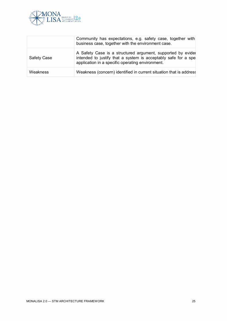
Community has expectations, e.g. safety case, together with thbusiness case, together with the environment case.
Safety CaseA Safety Case is a structured argument, supported by evidence,intended to justify that a system is acceptably safe for a specificapplication in a specific operating environment.
Weakness Weakness (concern) identified in current situation that is addressed.

MONALISA 2.0 — STM ARCHITECTURE FRAMEWORK 26
5.4.8 Transition perspective
The main purpose is to package and communicate the operational changes and to plan the step-by-step increase of the benefit generated by STM until it reaches the full effect to maritime
transportation.
Figure 12 Metamodel for Transition perspective
Transition Perspective
BusinessPerspective
OperationalImprovement
Step
MajorOperational
Change
Line of Change
Enabler
Operational Perspective
Current Situation STM Target Concept
Stakeholder
OperationalService
ImprovementPhase
ProceduralEnabler
InstitutionalEnabler
HumanEnabler
SystemEnabler
Weakness
Gap
OperationalImprovement
Group
ServiceEnabler
StakeholderGroup
OperationalDescription
realises
plannedfor
grouped in
decomposedto
realises
set of
belongingto
planned for

MONALISA 2.0 — STM ARCHITECTURE FRAMEWORK 27
Architecture Element Description
Improvement PhaseThe transition from today’s situation to the STM TargetConcept is formulated through a sequence ofImprovement Phases describing the evolution of STM.
Major Operational Change
A major operational change is what is needed to bechanged operationally based on the gap between thecurrent situation and STM Target Concept. Eachidentified major operational change reflects a specificOperational Service within the STM Target Concept.
Operational Improvement Group A grouping of Operational Improvement Steps that isrelated or contributing to the same benefit or process.
Operational Improvement Step
An Operational Improvement Step describes a specificoperational change that can be implemented in a givenperiod of time, and results in a performanceenhancement.
Enabler
An Enabler is a change to the supporting infrastructurethese changes are actions proposed to be performed byvarious Stakeholders – i.e. an identification whereStakeholders may contribute to the evolution of themaritime domain. Enablers are what need to be donewhen implementing Operational Improvement Step.
Line of Change
A grouping of related Operational Improvement Groups toLine of Change that affects a certain operational area.The Line of Changes is a support to ensure that theplanning of the evolution to the STM Target Concept willmeet the required performance over time.
MONALISA 2.0 — STM ARCHITECTURE FRAMEWORK 28
6 STM Architecture Framework for vantage pointsThe following vantage points (various positions from which the domain has been viewed) havebeen considered:
· Current Situation· STM Performance Target· STM Target Concept· STM Strategic Roadmap and Master Plan· STM E-Master Plan
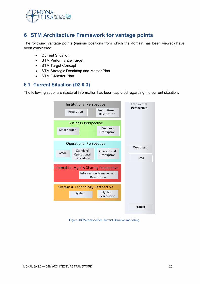
6.1 Current Situation (D2.0.3)The following set of architectural information has been captured regarding the current situation.
Figure 13 Metamodel for Current Situation modelling
Business Perspective
TransversalPerspective
System & Technology Perspective
Institutional Perspective
Weakness
Project
System
Regulation
Operational Perspective
StandardOperationalProcedure
Actor
Stakeholder BusinessDescription
OperationalDescription
InstitutionalDescription
Systemdescription
Need
Information Mgm & Sharing PerspectiveInformation Management
Description
MONALISA 2.0 — STM ARCHITECTURE FRAMEWORK 29
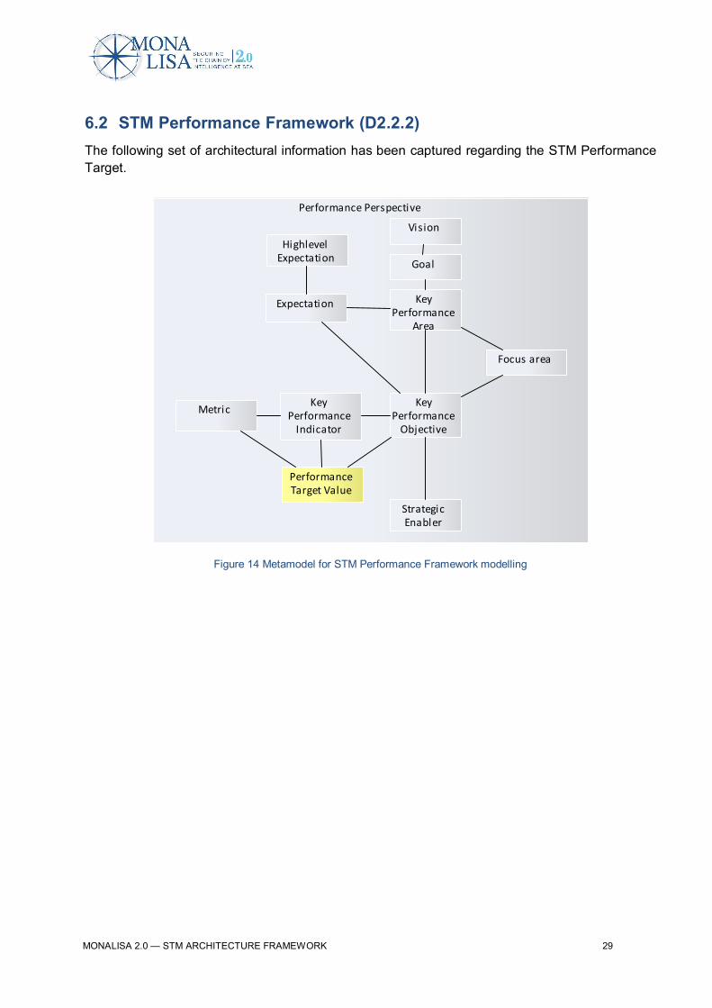
6.2 STM Performance Framework (D2.2.2)The following set of architectural information has been captured regarding the STM PerformanceTarget.
Figure 14 Metamodel for STM Performance Framework modelling
Performance Perspective
Vision
Goal
HighlevelExpectation
Expectation KeyPerformance
Area
Focus area
KeyPerformance
Objective
KeyPerformance
Indicator
Metric
PerformanceTarget Value
StrategicEnabler
MONALISA 2.0 — STM ARCHITECTURE FRAMEWORK 30
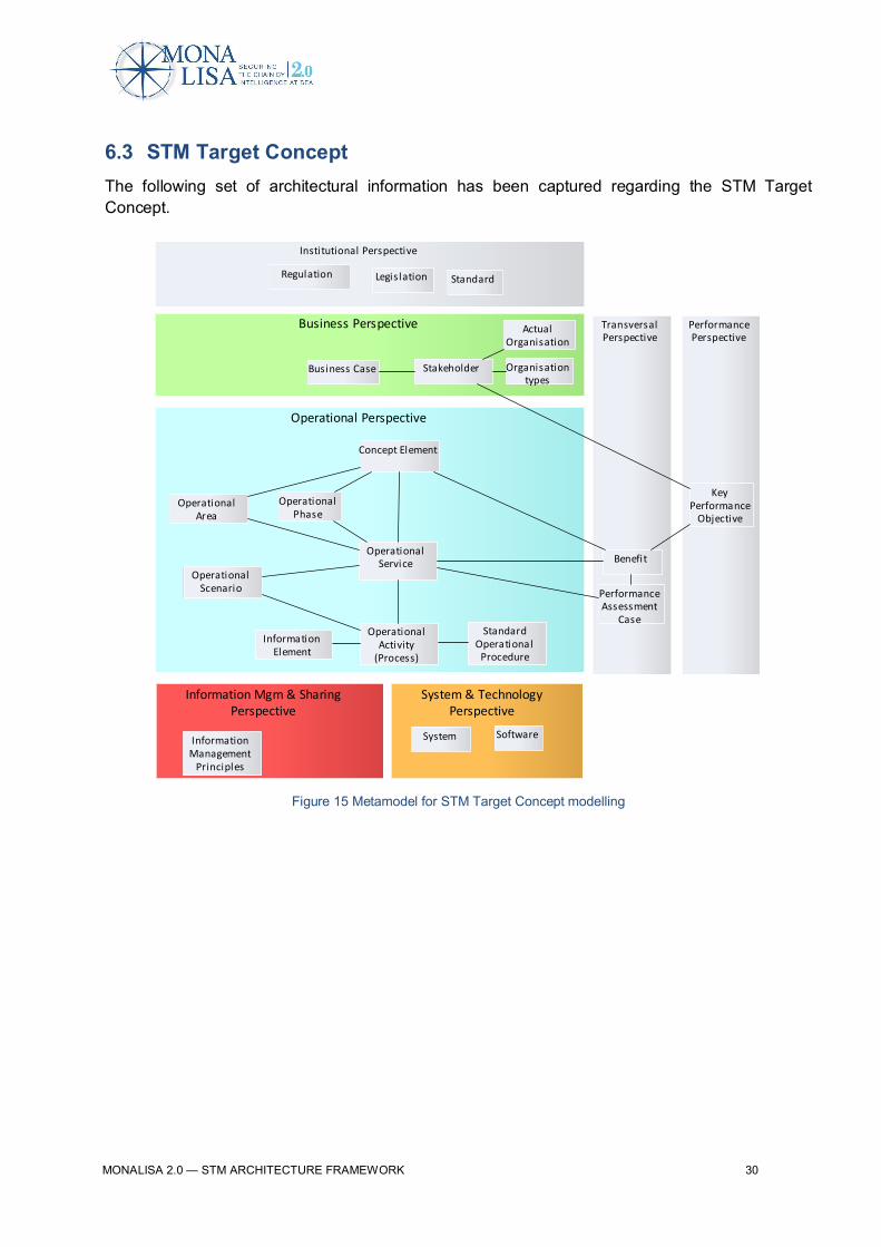
6.3 STM Target ConceptThe following set of architectural information has been captured regarding the STM TargetConcept.
Figure 15 Metamodel for STM Target Concept modelling
Information Mgm & SharingPerspective
Operational Perspective
Concept Element
OperationalService
Business Perspective
Business Case
TransversalPerspective
Benefit
InformationElement
OperationalPhase
OperationalArea
OperationalActivity
(Process)
StandardOperational
Procedure
OperationalScenario
InformationManagement
Principles
System & TechnologyPerspective
System Software
Stakeholder Organisationtypes
ActualOrganisation
Institutional Perspective
Regulation Legislation Standard
PerformancePerspective
KeyPerformance
Objective
PerformanceAssessment
Case
MONALISA 2.0 — STM ARCHITECTURE FRAMEWORK 31
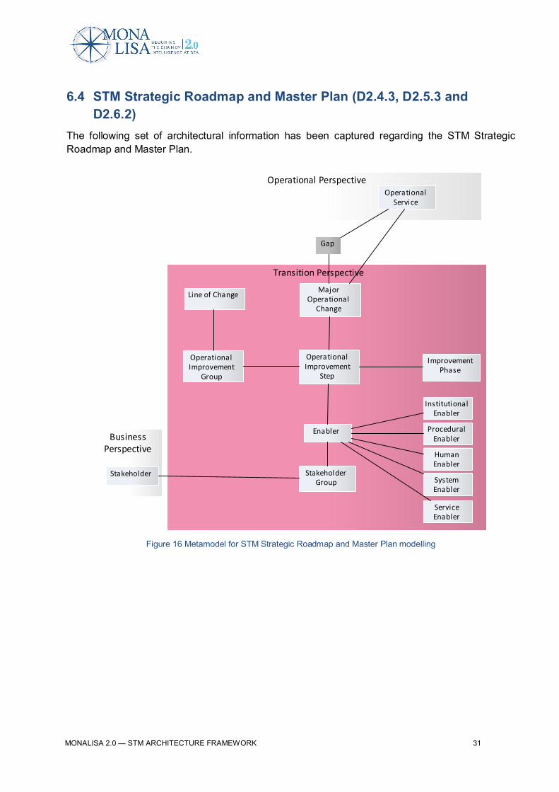
6.4 STM Strategic Roadmap and Master Plan (D2.4.3, D2.5.3 andD2.6.2)
The following set of architectural information has been captured regarding the STM StrategicRoadmap and Master Plan.
Figure 16 Metamodel for STM Strategic Roadmap and Master Plan modelling
Operational Perspective
Transition Perspective
BusinessPerspective
OperationalImprovement
Step
MajorOperational
Change
Line of Change
Enabler
Stakeholder
OperationalService
ImprovementPhase
ProceduralEnabler
InstitutionalEnabler
HumanEnabler
SystemEnabler
Gap
OperationalImprovement
Group
ServiceEnabler
StakeholderGroup

MONALISA 2.0 — STM ARCHITECTURE FRAMEWORK 32
6.5 STM e-Master PlanThe following set of architectural information has been captured regarding the STM E-MasterPlan.
Figure 17 Metamodel for e-Master Plan modelling part
Current Si tuation
STM Target Concept
STM Performance Target
EN-nnn - Enabler
Elements in e-Master Plan
«Stakeholder Group»Stakeholder Group
Line of Change
OG-nn - OperationalImprovement Group
«IP»Improvement
Phase
OI-nnn -Operational
Improvement Step
«Procedural Enabler»EN-nnn - Enabler
«Insti tutional Enabler»EN-nnn - Enabler
«Human Enabler»EN-nnn - Enabler
«System Enabler»EN-nnn - Enabler
«Service Enabler»EN-nnn - Enabler
<<KPO>>Key Performance
Objective
«MOC»Major Operational
Change
«Gap»Gap
Organisation
«Operational Service»Operational Service
Weakness
<<KPA>>Key Performance
Area
<<KPI>>Key Performance
Indicator
«Focus Area»Focus Area
<<Vision>>Vision
«STM Goal»Goal

MONALISA 2.0 — STM ARCHITECTURE FRAMEWORK 33
7 Graphical and Model NotationThe main part of the STM Architecture Description has been modelled using simple UML classnotation and associations between architectural elements. Stereotypes have been used for settingcolour and form.
8 Report generation
8.1 Document reportsReports are generated to be included in documents (such as this document) and for workingmaterial.
8.2 ExcelInformation has been generated in Excel sheets to be included in documents and as workingmaterial.
9 ToolsEnterprise Architect from Sparx systems version 10 has been used as the main repository.
MS Office has been used for supplementary modelling.
10 ReferencesISO, 2012, ISO 42010:2012 Systems and software engineering – Architecture description
MoD UK, n d, Ministry of Defence Architecture Framework
NATO, n d, NATO Architecture Framework
MONALISA 2.0 — STM ARCHITECTURE FRAMEWORK 34
Appendix A Activity 2 DeliverablesThis appendix lists the MONALISA 2.0 Activity 2 deliverables.
· ATM report for MONALISA 2.0, MONALISA 2.0 – D2.0.7, 2015· Collaboration in the Maritime Transport Ecosystem, MONALISA 2.0 – D2.3.1-12-3,
2015· Dynamic Voyage Management Concept Description, MONALISA 2.0 – D2.3.1-4.2,
2015.· Electronic STM Master Plan, MONALISA 2.0 – D2.5.2, http://stmmasterplan.com· Envisioning Sea Traffic Management 2030, MONALISA 2.0 – D2.3.1-12-4, 2015· Finding Information in the Maritime Transport Ecosystem, MONALISA 2.0 – D2.3.1-12-
2,· Flow Management Concept Description, MONALISA 2.0 – D2.3.1-4.3, 2015.· Formal Safety Assessment Case, MONALISA 2.0 – D2.3.1-11, 2015· Green Steaming: A Methodology for Estimating Carbon Emissions (2015) Avoided,
Watson, R., H. Holm, and M. Lind, Thirty Sixth International Conference on InformationSystems, Fort Worth
· Performance Assessment Case, MONALISA 2.0 -- D2.3.1-9, 2015· Port CDM Concept Description, MONALISA 2.0 – D2.3.1-4.4, 2015· Port CDM Report, MONALISA 2.0 – D2.7.1, 2015· Sea Traffic Management: A Holistic View, MONALISA 2.0 – D2.3.1-4.0, 2015· Sea Voyage Costs, MONALISA 2.0 – D2.3.1-3.2, 2015· STM – The Current situation, MONALISA 2.0 – D2.1.1, 2015· STM – The Target Concept, MONALISA 2.0 – D2.3.1, 2015· STM Master Plan, MONALISA 2.0 – D2.5.1, 2015· STM Performance Framework, MONALISA 2.0 – D2.2.1, 2015· Strategic Voyage Management Concept Description, MONALISA 2.0 – D2.3.1-4.1,
2015· Target Business Description, MONALISA 2.0 – D2.3.1-3, 2015· Target Concept Business Case, MONALISA 2.0 – D2.3.1-2, 2015· Target Human Aspects Description, MONALISA 2.0 – D2.3.1-7, 2015· Target Information-Systems and Information-Technology Description, MONALISA 2.0 –
D2.3.1-6, 2015· Target Institutional Description, MONALISA 2.0 – D2.3.1-1, 2015· Target Systems Technical and Technology Description, MONALISA 2.0 – D2.3.1-5,
2015· Target Transversal Aspects Description, MONALISA 2.0 – D2.3.1-8, 2015· Understanding the Maritime Transport Ecosystem, MONALISA 2.0 – D2.3.1-12-1
MONALISA 2.0 — STM ARCHITECTURE FRAMEWORK 35
39 partners from 10 countriestaking maritime transport into the digital age
By designing and demonstrating innovative use of ICT solutionsMONALISA 2.0 will provide the route to improved
SAFETY - ENVIRONMENT - EFFICIENCY
Swedish Maritime Administration ◦ LFV - Air Navigation Services of Sweden ◦ SSPA ◦ ViktoriaSwedish ICT ◦ Transas ◦ Carmenta ◦ Chalmers University of Technology ◦ World Maritime
University ◦ The Swedish Meteorological and Hydrological Institute ◦ Danish Maritime Authority ◦Danish Meteorological Institute ◦ GateHouse ◦ Navicon ◦ Novia University of Applied Sciences ◦DLR ◦ Fraunhofer ◦ Jeppesen ◦ Rheinmetall ◦ Carnival Corp. ◦ Italian Ministry of Transport ◦
RINA Services ◦ D’Appolonia ◦ Port of Livorno ◦ IB SRL ◦ Martec SPA ◦ Ergoproject ◦ University ofGenua ◦ VEMARS ◦ SASEMAR ◦ Ferri Industries ◦ Valencia Port Authority ◦ Valencia Port
Foundation ◦ CIMNE ◦ Corporacion Maritima ◦ Technical University of Madrid ◦ University ofCatalonia ◦ Technical University of Athens ◦MARSEC-XL ◦ Norwegian Coastal Administration
www.monalisaproject.eu