Spacecraft - S3L · 2018-12-12 · (e.g. Plan, document, file, report, form, matrix) DRL item...
85
Copyright © 2017 by SPACEBEL – All rights reserved Spacecraft On Board Software December 2017 December 2017 On Board Software Overview for ULg
Transcript of Spacecraft - S3L · 2018-12-12 · (e.g. Plan, document, file, report, form, matrix) DRL item...

Cop
yri
gh
t ©
20
17
by S
PA
CE
BE
L –
All r
igh
ts r
ese
rve
d Spacecraft
On Board Software
December 2017
December 2017 On Board Software Overview for ULg

Cop
yri
gh
t ©
20
17
by S
PA
CE
BE
L –
All r
igh
ts r
ese
rve
d
December 2017 On Board Software Overview for ULg
● OBSW Characteristics
● OBSW Process
● OBSW Architecture
● OBSW Environments

Cop
yri
gh
t ©
20
17
by S
PA
CE
BE
L –
All r
igh
ts r
ese
rve
d
December 2017 On Board Software Overview for ULg
● OBSW Characteristics
● OBSW Process
● OBSW Architecture
● OBSW Environments

Cop
yri
gh
t ©
20
17
by S
PA
CE
BE
L –
All r
igh
ts r
ese
rve
d
December 2017 On Board Software Overview for ULg
● OBSW Characteristics
● OBSW Constraints
● OBSW Dependability
● OBSW Criticality
● OBSW Properties
● OBSW Processes
● OBSW Architectures
● OBSW Environments

Cop
yri
gh
t ©
20
17
by S
PA
CE
BE
L –
All r
igh
ts r
ese
rve
d
OBSW: Constraints On Board Softyware > Characteristics > Contraints
December 2017 On Board Software Overview for ULg
● Embedded Software Cross Development Environment, bounded Memory Footprint and Processor Consumption
● On Board Software Single Event Effects (Upset, Latch Up), Memory Scrubbing
● Real Time Software Processor load, scheduling issues, deadlines
● Deterministic Software No dynamic thread creation or memory allocation, budget and schedulability
● Remote Software Need for autonomy
● Critical Software (see further down)
Possible catastrophic consequences of failure
● Dependable Software (see further down)
Need for high Reliability, Availability, Maintainability and Safety
On Board Software has to cope with constraints stemming from its execution environment in space:
Cop
yri
gh
t ©
20
17
by S
PA
CE
BE
L –
All r
igh
ts r
ese
rve
d
December 2017 On Board Software Overview for ULg
● OBSW Characteristics
● OBSW Constraints
● OBSW Dependability
● OBSW Criticality
● OBSW Properties
● OBSW Process
● OBSW Architectures
● OBSW Environments

Cop
yri
gh
t ©
20
17
by S
PA
CE
BE
L –
All r
igh
ts r
ese
rve
d
OBSW: Dependability On Board Software > Characteristics > Dependability
December 2017 On Board Software Overview for ULg
RAMS
•Reliability: continuity of correct service.
•Availability: readiness for usage.
•Maintainability: easiness of repair/upgrade.
•Safety: non-occurrence of catastrophic failure
Strategies
•Fault Prevention avoidance and reduction of fault causes
•Fault Tolerance avoidance and reduction of fault consequences
•Fault Removal removal of fault occurrences
•Fault Forecasting prediction of behaviour in presence of faults
FDIR
•Fault hardware or software
•Detection e.g. through monitoring
•Isolation determination of the cause
•Recovery e.g through redundancy
Analysis
•SCA: Software Criticality Analysis (see next slide)
•HSIA: Hardware Software Interaction Analysis
•FMECA:
Failure Mode Effects and Criticality Analysis
•FTA: Fault Tree Analysis
•FHA Functional Hazard Analysis
•SCCFA: Software Common Causes Failure Analysis
FDIR is imperative to guarantee a dependable and autonomous system with a minimal risk of ruinous failure
•Integrity Maintenance of data consistency
•Security Non disclosure of unauthorized info
•Certifiability Ability to get stamp from certification body
Troubles
•Error: A wrong or missing human action or thought
•Fault: An incorrect step, process or data definition in a program
•Failure: The inability of the software to perform its required functions.
Achieving mission objectives and ultimate mission success relies on dependability of the space systems and of the software.
As software plays more and more a prominent role in space systems, its contribution to the overall system dependability becomes a vital aspect of system development

Cop
yri
gh
t ©
20
17
by S
PA
CE
BE
L –
All r
igh
ts r
ese
rve
d
December 2017 On Board Software Overview for ULg
● OBSW Characteristics
● OBSW Constraints
● OBSW Dependability
● OBSW Criticality
● OBSW Properties
● OBSW Process
● OBSW Architectures
● OBSW Environments

Cop
yri
gh
t ©
20
17
by S
PA
CE
BE
L –
All r
igh
ts r
ese
rve
d
OBSW: Criticality On Board Software > Characteristics > Criticality
December 2017 On Board Software Overview for ULg
Critical Software is a Software that if not executed or if not correctly executed or whose anomalous behaviour
could cause or contribute to a System Failure resulting in :
A: Catastrophic Consequences
Loss of Life, life threatening, personnel injuries, permanently disabling injury or occupational illness, Loss of an element of an interfacing manned flight system. Damage to other equipment. Loss of launch site facility facilities or loss of system. Severe detrimental environmental effects.
B: Critical
Consequences
Permanent or non-recoverable loss of the satellite’s capability to perform its planned mission Temporarily disabling but not life-threatening injury or occupational illness. Major damage to flight system or loss or major damage to ground facilities. Major damage to public or private property or major detrimental environmental effects.
C: Major
Consequences
Negligible or minor effect on the satellite’s mission and operability A detailed definition is left on a project by project basis and reported in its risk policy. Example is Mission Simulation Software
D: Minor
Consequences
A detailed definition is left on a project by project basis and reported in its risk policy. Example is Test Software
In the DO-178-C (Software Considerations in Airborne Systems ), the Design Assurance Level (DAL) is determined from the safety assessment process and hazard analysis
by examining the effects of a failure condition in the system. The failure conditions are categorized by their effects on the aircraft, crew, and passengers (catastrophic, severe/hazardous, major, minor, no effect).

Cop
yri
gh
t ©
20
17
by S
PA
CE
BE
L –
All r
igh
ts r
ese
rve
d
December 2017 On Board Software Overview for ULg
● OBSW Characteristics
● OBSW Constraints
● OBSW Dependability
● OBSW Criticality
● OBSW Properties
● OBSW Process
● OBSW Architectures
● OBSW Environments
Cop
yri
gh
t ©
20
17
by S
PA
CE
BE
L –
All r
igh
ts r
ese
rve
d
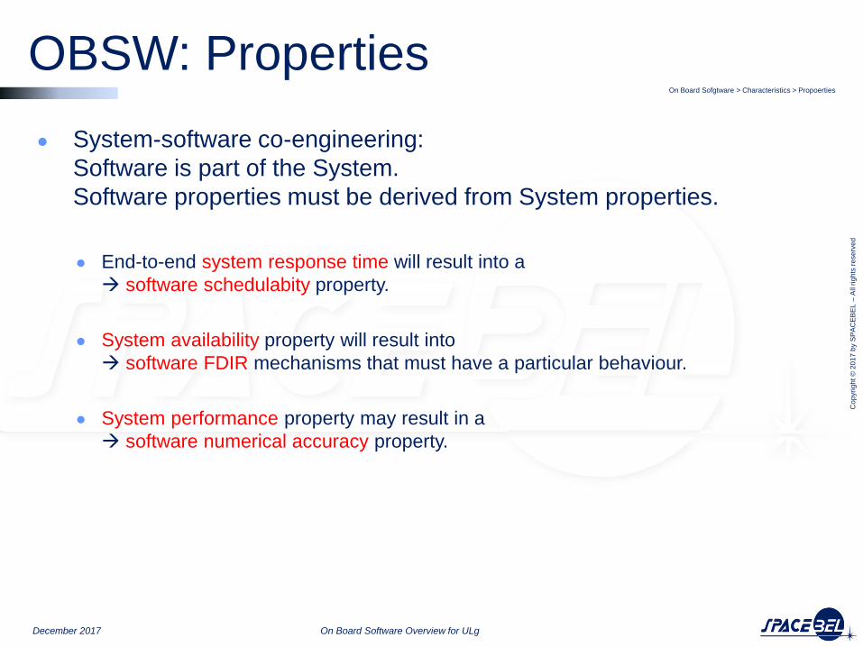
● System-software co-engineering:
Software is part of the System.
Software properties must be derived from System properties.
● End-to-end system response time will result into a
software schedulabity property.
● System availability property will result into
software FDIR mechanisms that must have a particular behaviour.
● System performance property may result in a
software numerical accuracy property.
On Board Sofgtware > Characteristics > Propoerties
December 2017 On Board Software Overview for ULg
OBSW: Properties

Cop
yri
gh
t ©
20
17
by S
PA
CE
BE
L –
All r
igh
ts r
ese
rve
d
December 2017 On Board Software Overview for ULg
● OBSW Characteristics
● OBSW Process
● OBSW Architectures
● OBSW Environments

Cop
yri
gh
t ©
20
17
by S
PA
CE
BE
L –
All r
igh
ts r
ese
rve
d
December 2017 On Board Software Overview for ULg
● OBSW Characteristics
● OBSW Process
● OBSW Phases
● OBSW Lifecycle
● OBSW Verification
● OBSW Standards
● OBSW Documentation
● OBSW Architectures
● OBSW Environments

Cop
yri
gh
t ©
20
17
by S
PA
CE
BE
L –
All r
igh
ts r
ese
rve
d
OBSW: Phases On Board Software > Process > Phases
December 2017 On Board Software Overview for ULg
On Board Software usually comes (too) late in the overall spacecraft development:
Cop
yri
gh
t ©
20
17
by S
PA
CE
BE
L –
All r
igh
ts r
ese
rve
d
December 2017 On Board Software Overview for ULg
● OBSW Characteristics
● OBSW Process
● OBSW Phases
● OBSW Lifecycle
● OBSW Verification
● OBSW Standards
● OBSW Documentation
● OBSW Architectures
● OBSW Environments

Cop
yri
gh
t ©
20
17
by S
PA
CE
BE
L –
All r
igh
ts r
ese
rve
d
OBSW: Lifecycle On Board Software > Process > Lifecycle
December 2017 On Board Software Overview for ULg
Requirement Baseline
Software Specification
Detailed Design
Coding
Preliminary Design
Validation Test
Integration Test
Unit Test
Qualification Test
Source Code, Executable, Makefiles, Scripts
SRR
PDR
(DDR)
PMP, PAP, CMP, SDP, SVVP RFI, RFQ, RFP, ITT, SOW
VTR, VCD
ITR
UTR SDD-AD, ICD’
SRS, ICD
SDD-DD
SSS,IRS,OCD
SUM,COM, SPS
CDR
QR
AR
ATP
VTP
ITP
UTP
Phase A
Phase B
Phase C
Phase D
Phase E
(DRB)
(TRB)
(TRR)
On Board Software development follows a formal Lifecycle

Cop
yri
gh
t ©
20
17
by S
PA
CE
BE
L –
All r
igh
ts r
ese
rve
d
December 2017 On Board Software Overview for ULg
● OBSW Characteristics
● OBSW Process
● OBSW Phases
● OBSW Lifecycle
● OBSW Verification
● OBSW Standards
● OBSW Documentation
● OBSW Architectures
● OBSW Environments

Cop
yri
gh
t ©
20
17
by S
PA
CE
BE
L –
All r
igh
ts r
ese
rve
d
OBSW: Verification & Validation On Board Software > Process > Verification and Validation
December 2017 On Board Software Overview for ULg
Independent Sofware Verification and Validation is performed by an independent team or company in addition to normal Verification and Validation (required for Cat B)
On Board Software Verification and Validation represent a very significant part of the total development effort
Verification Validation All Along the Development At the end of the Development
Through Reviews and Analysis
Peer Review
Cross Reading
Static Code Analysis
Schedulability Analysis
Through Tests Campaign
(Unit Tests) against Detailed Design
(Integration Tests) against Architecture and Interface Definition
Validation Tests* against Technical Specification
Qualification Tests against Requirement Baseline
Supported by Software Engineering Tools Model Verifiers
Static Code Analyzer Traceability Matrices
Supported by Test Facilities Software Test Benches
Hardware Models Hybrid Facilities
*some requirement may alternatively be validated by Analogy, by Analysis of Design, by Inspection of Code

Cop
yri
gh
t ©
20
17
by S
PA
CE
BE
L –
All r
igh
ts r
ese
rve
d
December 2017 On Board Software Overview for ULg
● OBSW Characteristics
● OBSW Process
● OBSW Phases
● OBSW Lifecycle
● OBSW Verification
● OBSW Standards
● OBSW Documentation
● OBSW Architectures
● OBSW Environments
Cop
yri
gh
t ©
20
17
by S
PA
CE
BE
L –
All r
igh
ts r
ese
rve
d
OBSW : Standards On Board Software > Process > Standards
December 2017 On Board Software Overview for ULg
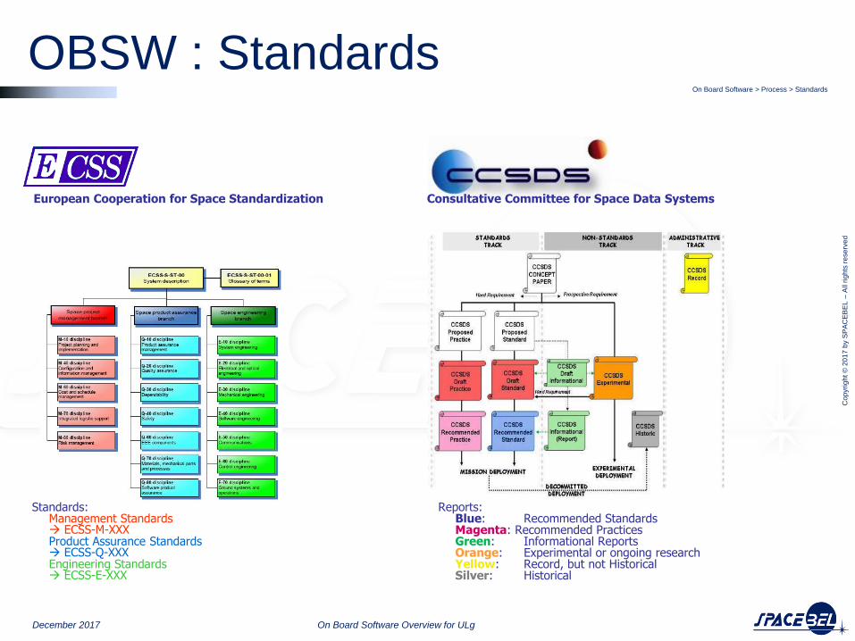
European Cooperation for Space Standardization
Reports: Blue: Recommended Standards Magenta: Recommended Practices Green: Informational Reports Orange: Experimental or ongoing research Yellow: Record, but not Historical Silver: Historical
Standards: Management Standards ECSS-M-XXX Product Assurance Standards ECSS-Q-XXX Engineering Standards ECSS-E-XXX
Consultative Committee for Space Data Systems

Cop
yri
gh
t ©
20
17
by S
PA
CE
BE
L –
All r
igh
ts r
ese
rve
d
December 2017 On Board Software Overview for ULg
● OBSW Characteristics
● OBSW Process
● OBSW Phases
● OBSW Lifecycle
● OBSW Verification
● OBSW Standards
● OBSW Documentation
● OBSW Architectures
● OBSW Environments
Cop
yri
gh
t ©
20
17
by S
PA
CE
BE
L –
All r
igh
ts r
ese
rve
d
OBSW : Documentation OBSW > Process > Documentation
December 2017 On Board Software Overview for ULg
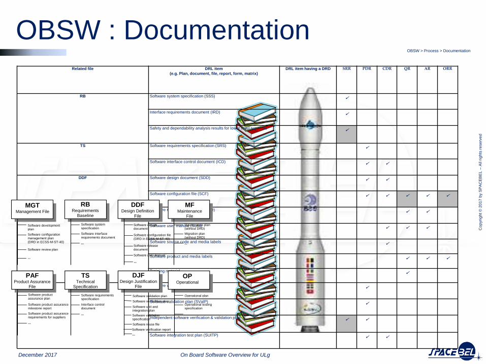
Related file DRL item
(e.g. Plan, document, file, report, form, matrix)
DRL item having a DRD SRR PDR CDR QR AR ORR
RB Software system specification (SSS)
Interface requirements document (IRD)
Safety and dependability analysis results for lower level suppliers
TS Software requirements specification (SRS)
Software interface control document (ICD)
DDF Software design document (SDD)
Software configuration file (SCF)
Software release document (SRelD)
Software user manual (SUM)
Software source code and media labels
Software product and media labels
Training material
DJF Software verification plan (SVerP)
Software validation plan (SValP)
Independent software verification & validation plan
Software integration test plan (SUITP)
Software configuration management plan (DRD in ECSS-M-ST-40)
Software review plan
...
Software system specification
Software interface requirements document
...
Software design document Software configuration file (DRD in ECSS-M-ST-40) Software release document
... Software user manual
Maintenance plan (without DRD) Migration plan (without DRD) ...
PAF Product Assurance
File
TS Technical
Specification
DJF Design Justification
File
OP Operational
Software product assurance plan Software product assurance milestone report
Software product assurance requirements for suppliers ...
Software requirements specification Interface control document ...
Software validation plan Software verification plan Software unit and integration plan
...
Software reuse file
Operational plan
Operational testing specification ...
Software development plan
MF Maintenance
File
MGT Management File
DDF Design Definition
File
Software validation specification
Software verification report
RB Requirements
Baseline

Cop
yri
gh
t ©
20
17
by S
PA
CE
BE
L –
All r
igh
ts r
ese
rve
d
December 2017 On Board Software Overview for ULg
● OBSW Characteristics
● OBSW Process
● OBSW Architectures
● OBSW Environments
Cop
yri
gh
t ©
20
17
by S
PA
CE
BE
L –
All r
igh
ts r
ese
rve
d
December 2017 On Board Software Overview for ULg
● OBSW Characteristics
● OBSW Process
● OBSW Architectures
● OBSW Functional Architecture
● OBSW Static Architecture
● OBSW Interfaces & Data Flows
● OBSW Dynamic Architecture
● OBSW Deployement Architecture
● OBSW Environments
Cop
yri
gh
t ©
20
17
by S
PA
CE
BE
L –
All r
igh
ts r
ese
rve
d
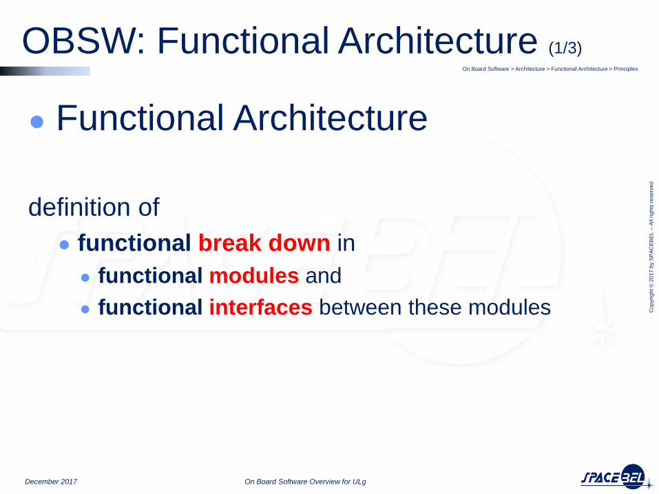
● Functional Architecture
definition of
● functional break down in
● functional modules and
● functional interfaces between these modules
On Board Software > Architecture > Functional Architecture > Principles
December 2017 On Board Software Overview for ULg
OBSW: Functional Architecture (1/3)
Cop
yri
gh
t ©
20
17
by S
PA
CE
BE
L –
All r
igh
ts r
ese
rve
d
Functional Architecture (2/3) On Board Software > Architecture > Functional Architecture > Functional Breakdown
December 2017 On Board Software Overview for ULg
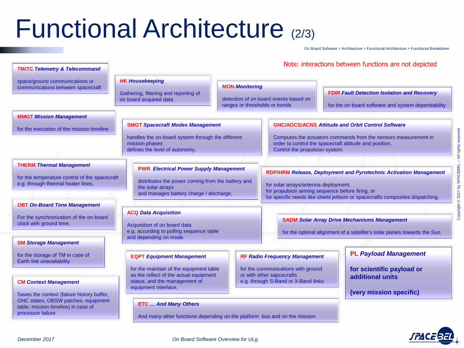
TM/TC Telemetry & Telecommand
space/ground communications or
communications between spacecraft
HK Housekeeping
Gathering, filtering and reporting of
on board acquired data
MON Monitoring
detection of on board events based on
ranges or thresholds or trends
OBT On-Board Time Management
For the synchronization of the on-board
clock with ground time,
FDIR Fault Detection Isolation and Recovery
for the on board software and system dependability
GNC/AOCS/ACNS Attitude and Orbit Control Software
Computes the actuators commands from the sensors measurement in
order to control the spacecraft attitude and position.
Control the propulsion system.
RF Radio Frequency Management
for the communications with ground
or with other sapcecrafts
e.g. through S-Band or X-Band links. CM Context Management
Saves the context (failure history buffer,
GNC states, OBSW patches, equipment
table, mission timeline) in case of
processor failure.
SM Storage Management
for the storage of TM in case of
Earth link unavailability
THERM Thermal Management
for the temperature control of the spacecraft
e.g. through thermal heater lines,
PWR Electrical Power Supply Management
distributes the power coming from the battery and
the solar arrays
and manages battery charge / discharge,
SADM Solar Array Drive Mechanisms Management
for the optimal alignment of a satellite's solar panels towards the Sun.
RDP/HRM Release, Deployment and Pyrotechnic Activation Management
for solar arrays/antenna deployment,
for propulsion arming sequence before firing, or
for specific needs like shield jettison or spacecrafts composites dispatching,
PL Payload Management
for scientific payload or
additional units
(very mission specific)
EQPT Equipment Management
for the maintain of the equipment table
as the reflect of the actual equipment
status, and the management of
equipment interface,
ACQ Data Acquisition
Acquisition of on board data
e.g. according to polling sequence table
and depending on mode
Note: interactions between functions are not depicted
SMGT Spacecraft Modes Management
handles the on-board system through the different
mission phases
defines the level of autonomy,
MMGT Mission Management
for the execution of the mission timeline
ETC … And Many Others
And many other functions depending on the platform bus and on the mission

Cop
yri
gh
t ©
20
17
by S
PA
CE
BE
L –
All r
igh
ts r
ese
rve
d
Functional Architecture (3/3)
On Board Software > Architecture> Functional Architecture > Variability
December 2017 On Board Software Overview for ULg
Mission
Operation
Avionics
Monitoring & Control Interfaces
Network
Processor
Mode Mgt
SYS SW
PL SW
PF SW
AOCS SW
DH SW
Processing
Commandability
Observability
Fault Mgt
Equipment Mgt
Processing
Telecommand Mgt
Telemetry Mgt
Fault Mgt
Components
Interaction Layer
Execution Platform

Cop
yri
gh
t ©
20
17
by S
PA
CE
BE
L –
All r
igh
ts r
ese
rve
d
December 2017 On Board Software Overview for ULg
● OBSW Characteristics
● OBSW Process
● OBSW Architectures
● OBSW Functional Architecture
● OBSW Static Architecture
● OBSW Interfaces & Data Flows
● OBSW Dynamic Architecture
● OBSW Deployement Architecture
● OBSW Environments

Cop
yri
gh
t ©
20
17
by S
PA
CE
BE
L –
All r
igh
ts r
ese
rve
d
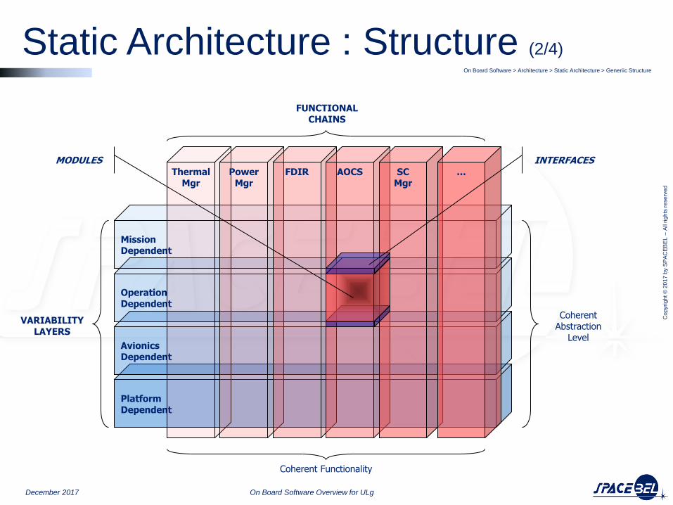
● Static architecture deals with ● Functional Properties ● Static Decomposition ● Software Component Model
● Software is broken down ● in software components (aka modules, units or objects) ● with clear interfaces between them
● Components are organized (see slide 2/4)
● horizontaly in variability layers with coherent abstraction level and ● verticaly in functional chains with coherent functionality
● Component are functional units (see slides 2-3-4/4)
● That encapsulate functional services, ● that expose these services to other components through well defined interfaces, and ● that can be assembled together to build a software product
● Components are made up of (see slide 3/4)
● Algorithms, State Machines ● Data Structures
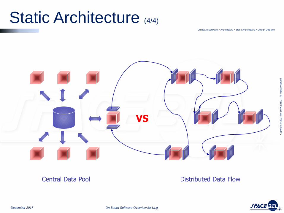
● Major design decision is (see slide 4/4)
● Central Data Pool vs ● Distributed Data Flows
● Main programming paradigms are ● Procedural programming vs ● Object Oriented programming (not used so far in on board software)
On Board Software > Architecture > Static Architecture > Principles
December 2017 On Board Software Overview for ULg
Static Architecture : Principles (1/4)
Cop
yri
gh
t ©
20
17
by S
PA
CE
BE
L –
All r
igh
ts r
ese
rve
d
Static Architecture : Structure (2/4) On Board Software > Architecture > Static Architecture > Generiic Structure
December 2017 On Board Software Overview for ULg
Platform Dependent
Avionics Dependent
Operation Dependent
Mission Dependent
Thermal Mgr
Power Mgr
FDIR AOCS SC Mgr
…
INTERFACES MODULES
VARIABILITY LAYERS
Coherent Abstraction
Level
FUNCTIONAL CHAINS
Coherent Functionality

Cop
yri
gh
t ©
20
17
by S
PA
CE
BE
L –
All r
igh
ts r
ese
rve
d
Static Architecture : Components (3/4) OBSW :> Architectures > Statoc Architecure > Component
December 2017 On Board Software Overview for ULg
On Board Software > Architecture > Static Architecture > Component
COMPONENT MODULE
UNIT OBJECT
Provided Interface
Required Interface
Functions Procedures
Methods
Data Structures
State Machines
Algorithms
Cop
yri
gh
t ©
20
17
by S
PA
CE
BE
L –
All r
igh
ts r
ese
rve
d
Static Architecture (4/4) On Board Software > Architecture > Static Architecture > Design Decision
December 2017 On Board Software Overview for ULg
VS
Central Data Pool Distributed Data Flow
Cop
yri
gh
t ©
20
17
by S
PA
CE
BE
L –
All r
igh
ts r
ese
rve
d
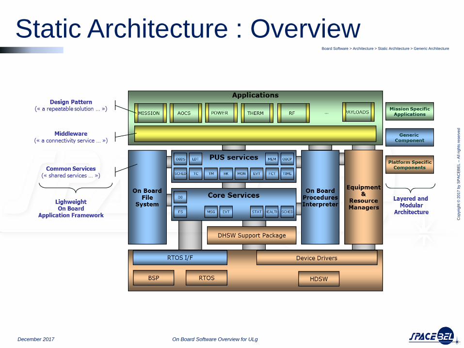
Static Architecture : Overview Board Software > Architecture > Static Architecture > Generic Architecture
December 2017 On Board Software Overview for ULg
Cop
yri
gh
t ©
20
17
by S
PA
CE
BE
L –
All r
igh
ts r
ese
rve
d
December 2017 On Board Software Overview for ULg
● OBSW Characteristics
● OBSW Process
● OBSW Architectures
● OBSW Functional Architecture
● OBSW Static Architecture
● OBSW Interfaces & Data Flows
● OBSW Dynamic Architecture
● OBSW Deployement Architecture
● OBSW Environments

Cop
yri
gh
t ©
20
17
by S
PA
CE
BE
L –
All r
igh
ts r
ese
rve
d
Interfaces & Data Flows On Board Software > Architecture > Interfaces & Data Flow
December 2017 On Board Software Overview for ULg
OBSW
Telecommands
•High Priority commands Hardware •Nominal commands Software •Macro commands Expanding •Time tagged commands Scheduling
Telemetry
•Housekeeping (Platform & Payload) Temperature, Pressure, Voltage and Current,Statuses
•Science Data (Payload)
e.g. Raw or compressed images
GND
Control Center
Space Ground Interface
Te
lem
etr
y
Te
leco
mm
an
d
PF Equipments
Platform Interfaces
PL Instruments
Payloads Interfaces
Science Data
Control
Command
Command
Control

Cop
yri
gh
t ©
20
17
by S
PA
CE
BE
L –
All r
igh
ts r
ese
rve
d
December 2017 On Board Software Overview for ULg
● OBSW Characteristics
● OBSW Process
● OBSW Architectures
● OBSW Functional Architecture
● OBSW Static Architecture
● OBSW Interfaces & Data Flows
● OBSW Dynamic Architecture
● OBSW Deployement Architecture
● OBSW Environments
Cop
yri
gh
t ©
20
17
by S
PA
CE
BE
L –
All r
igh
ts r
ese
rve
d
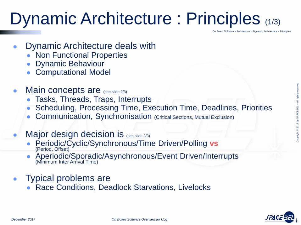
● Dynamic Architecture deals with ● Non Functional Properties ● Dynamic Behaviour ● Computational Model
● Main concepts are (see slide 2/3)
● Tasks, Threads, Traps, Interrupts ● Scheduling, Processing Time, Execution Time, Deadlines, Priorities ● Communication, Synchronisation (Critical Sections, Mutual Exclusion)
● Major design decision is (see slide 3/3)
● Periodic/Cyclic/Synchronous/Time Driven/Polling vs (Period, Offset)
● Aperiodic/Sporadic/Asynchronous/Event Driven/Interrupts (Minimum Inter Arrival Time)
● Typical problems are ● Race Conditions, Deadlock Starvations, Livelocks
On Board Software > Architecture > Dynamic Architecture > Principles
December 2017 On Board Software Overview for ULg
Dynamic Architecture : Principles (1/3)
Cop
yri
gh
t ©
20
17
by S
PA
CE
BE
L –
All r
igh
ts r
ese
rve
d
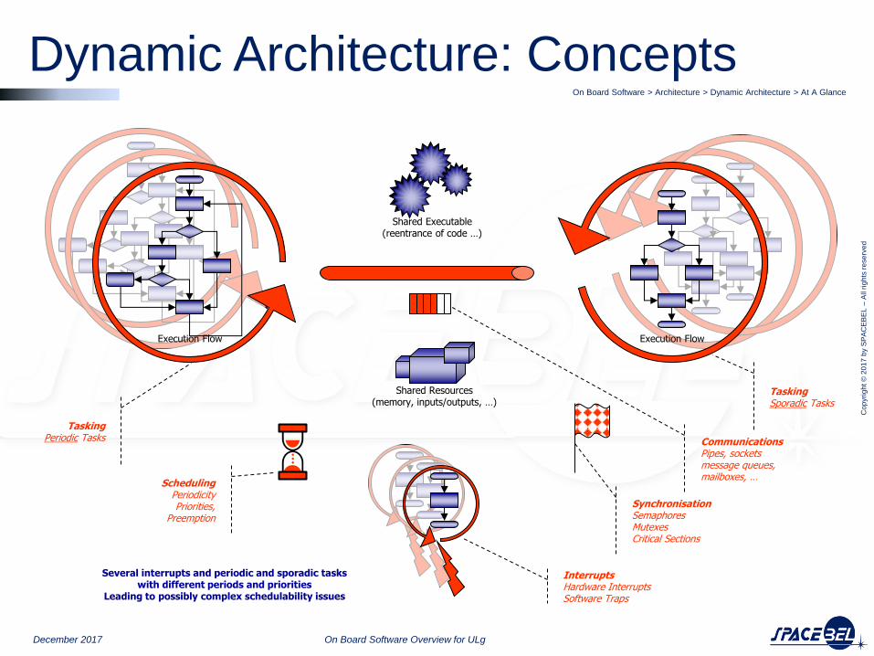
Shared Resources (memory, inputs/outputs, …)
Shared Executable (reentrance of code …)
Scheduling Periodicity Priorities,
Preemption
Synchronisation Semaphores Mutexes Critical Sections
Execution Flow Execution Flow
Communications Pipes, sockets message queues, mailboxes, …
Several interrupts and periodic and sporadic tasks with different periods and priorities
Leading to possibly complex schedulability issues
Interrupts Hardware Interrupts Software Traps
Tasking Periodic Tasks
Tasking Sporadic Tasks
Dynamic Architecture: Concepts On Board Software > Architecture > Dynamic Architecture > At A Glance
December 2017 On Board Software Overview for ULg
Cop
yri
gh
t ©
20
17
by S
PA
CE
BE
L –
All r
igh
ts r
ese
rve
d
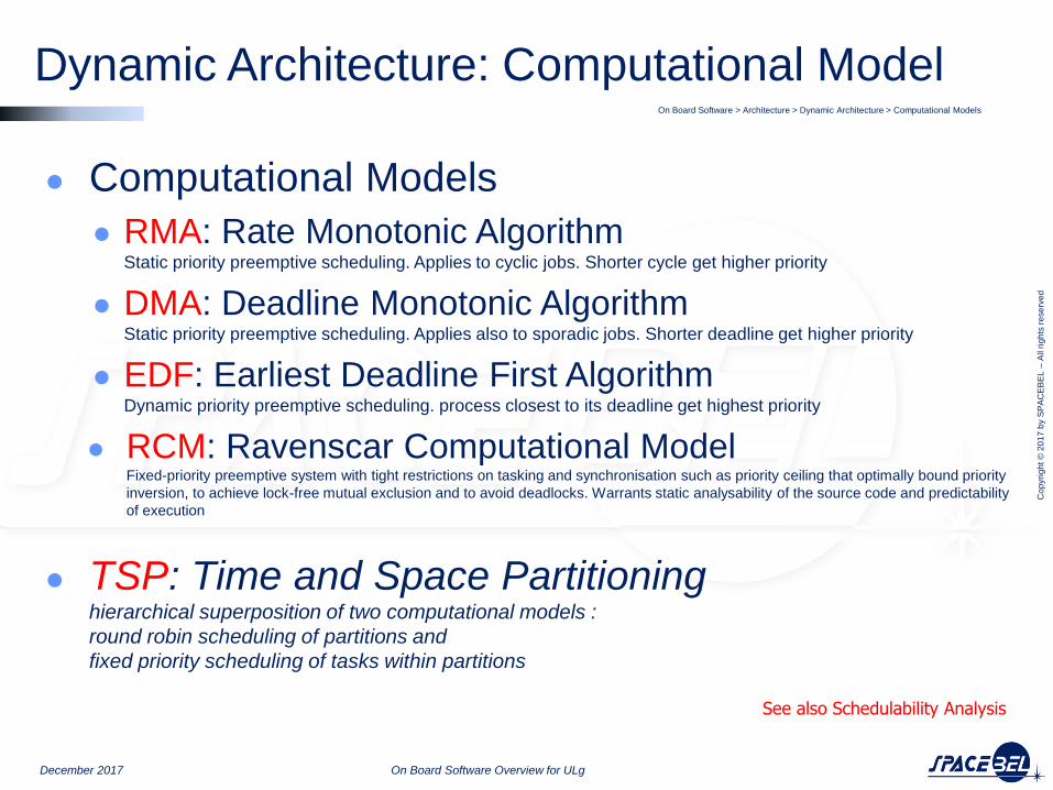
● Computational Models
● RMA: Rate Monotonic Algorithm Static priority preemptive scheduling. Applies to cyclic jobs. Shorter cycle get higher priority
● DMA: Deadline Monotonic Algorithm Static priority preemptive scheduling. Applies also to sporadic jobs. Shorter deadline get higher priority
● EDF: Earliest Deadline First Algorithm Dynamic priority preemptive scheduling. process closest to its deadline get highest priority
● RCM: Ravenscar Computational Model Fixed-priority preemptive system with tight restrictions on tasking and synchronisation such as priority ceiling that optimally bound priority
inversion, to achieve lock-free mutual exclusion and to avoid deadlocks. Warrants static analysability of the source code and predictability
of execution
● TSP: Time and Space Partitioning hierarchical superposition of two computational models :
round robin scheduling of partitions and
fixed priority scheduling of tasks within partitions
On Board Software > Architecture > Dynamic Architecture > Computational Models
December 2017 On Board Software Overview for ULg
Dynamic Architecture: Computational Model
See also Schedulability Analysis
Cop
yri
gh
t ©
20
17
by S
PA
CE
BE
L –
All r
igh
ts r
ese
rve
d
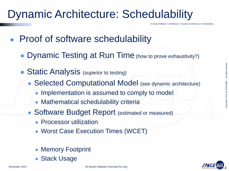
● Proof of software schedulability
● Dynamic Testing at Run Time (how to prove exhaustivity?)
● Static Analysis (superior to testing)
● Selected Computational Model (see dynamic architecture)
● Implementation is assumed to comply to model
● Mathematical schedulability criteria
● Software Budget Report (estimated or measured)
● Processor utilization
● Worst Case Execution Times (WCET)
● Memory Footprint
● Stack Usage
On Board Software > Architecture > Dynamic Architecture > Schedulability
December 2017 On Board Software Overview for ULg
Dynamic Architecture: Schedulability

Cop
yri
gh
t ©
20
17
by S
PA
CE
BE
L –
All r
igh
ts r
ese
rve
d
Formal Proof
Dynamic Architecture: Schedulability On Board Software > Architecture > Dynamic Architecture > Schedulability
December 2017 On Board Software Overview for ULg
Architecture
Implementation
Validation
Static Analysis
Mathematical
Model
Execution
Measurements
Computational
Model
Compliant
Implementation
•Rate Monotonic Scheduling
•Deadline Monotonic Scheduling
•Earliest Deadlin First
•Ravenscar Profile
(See Dynamic Architectures)
Processor Utilization
Worst Case Execution Time
(Based on realistic scenarios)
•Programming Model
•Design and Coding Rules
•Code Generation
Schedulability Condition
Compliance to a selected Computational Model allows for Static Analysis and Formal Check of Schedulability Conditions, based on corresponding Mathematical Model fed by actual Measurement from execution of realistic scenarios.
To this respect, Static analysis is superior to testing, which faces exhaustivity issue in real-scale systems.

Cop
yri
gh
t ©
20
17
by S
PA
CE
BE
L –
All r
igh
ts r
ese
rve
d
December 2017 On Board Software Overview for ULg
● OBSW Characteristics
● OBSW Process
● OBSW Architectures
● OBSW Functional Architecture
● OBSW Static Architecture
● OBSW Interfaces & Data Flows
● OBSW Dynamic Architecture
● OBSW Deployement Architecture
● OBSW Environments

Cop
yri
gh
t ©
20
17
by S
PA
CE
BE
L –
All r
igh
ts r
ese
rve
d
● Deployment Architecture deals with the Mapping ● of a logical architecture (software components) ● to a physical environment (hardware resources).
● Main concepts are ● Distribution ● Communication
● Main design decision is ● Centralised Architecture vs ● Distributed Architecture
● Main Solutions are ● Multi Processor
● Multi Core
● Time and Space Partitioning
On Board Software > Architecture > Deployment Architecture > Summmary
December 2017 On Board Software Overview for ULg
Deployment Architecture: Principles

Cop
yri
gh
t ©
20
17
by S
PA
CE
BE
L –
All r
igh
ts r
ese
rve
d
Deployment Architecture: Mapping On Board Software > Architecture > Deployment Architecture > Mapping
December 2017 On Board Software Overview for ULg
A deployment architecture depicts the mapping of a logical architecture (software components) to a physical environment (hardware resources).
The physical environment includes the computing nodes, processors, memory, storage devices, and other hardware and communication devices
Cop
yri
gh
t ©
20
17
by S
PA
CE
BE
L –
All r
igh
ts r
ese
rve
d
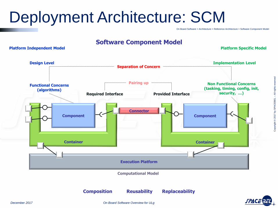
Deployment Architecture: SCM On Board Software > Architecture > Reference Architecture > Software Component Model
December 2017 On Board Software Overview for ULg
Component
Container
Component
Container
Connector
Design Level Implementation Level
Functional Concerns (algorithms)
Non Functional Concerns (tasking, timing, config, init,
security, …)
Platform Independent Model Platform Specific Model
Provided Interface Required Interface
Separation of Concern
Pairing up
Composition Reusability Replaceability
Execution Platform
Computational Model
Software Component Model

Cop
yri
gh
t ©
20
17
by S
PA
CE
BE
L –
All r
igh
ts r
ese
rve
d
December 2017 On Board Software Overview for ULg
● OBSW Characteristics
● OBSW Process
● OBSW Architectures
● OBSW Environments
● OBSW Execution Environment
● OBSW Development Environment

Cop
yri
gh
t ©
20
17
by S
PA
CE
BE
L –
All r
igh
ts r
ese
rve
d
OBSW Environment
December 2017 On Board Software Overview for ULg
Development Environment
Execution Environment
Cross Development Environment
Execution Environment:
On Board Computer with Limited Resources
Real Time Operating System with Constraints Software Executable
Development Environment:
Powerfull Development Workstations
Confortable Operating System Production Tools

Cop
yri
gh
t ©
20
17
by S
PA
CE
BE
L –
All r
igh
ts r
ese
rve
d
December 2017 On Board Software Overview for ULg
● OBSW Characteristics
● OBSW Process
● OBSW Architectures
● OBSW Environments
● OBSW Execution Environment
● Processors
● Operating Systems
● OBSW Development Environment

Cop
yri
gh
t ©
20
17
by S
PA
CE
BE
L –
All r
igh
ts r
ese
rve
d
December 2017 On Board Software Overview for ULg
● OBSW Characteristics
● OBSW Process
● OBSW Architectures
● OBSW Environments
● OBSW Execution Environment
● OB Processors
● OB Operating Systems
● OBSW Development Environment

Cop
yri
gh
t ©
20
17
by S
PA
CE
BE
L –
All r
igh
ts r
ese
rve
d
● Hardened Space Qualified processors 1990: 1750 – 16 Bits – 2 MIPS
2000 : ERC32 – SPARC V7 - 32 Bits – 20 Mhz – 14 MIPS
2010 : LEON2 – SPARC V8 - 32 Bits – Cache – Pipeline -100 Mhz – 84 MIPS
2105 : LEON3/4– Quad Core LEON
● Commercial of the Shelf
● ARM ● Power PC 1600 MIPS but sensitive to SEEs
See Avionics Overview
On Board Software > Environments > Execution Environment > Processorxs
December 2017 On Board Software Overview for ULg
Exec Environment: Processors
Cop
yri
gh
t ©
20
17
by S
PA
CE
BE
L –
All r
igh
ts r
ese
rve
d
December 2017 On Board Software Overview for ULg
● OBSW Characteristics
● OBSW Process
● OBSW Architectures
● OBSW Environments
● OBSW Execution Environment
● OB Processors
● OB Operating Systems
● OBSW Development Environment
Cop
yri
gh
t ©
20
17
by S
PA
CE
BE
L –
All r
igh
ts r
ese
rve
d
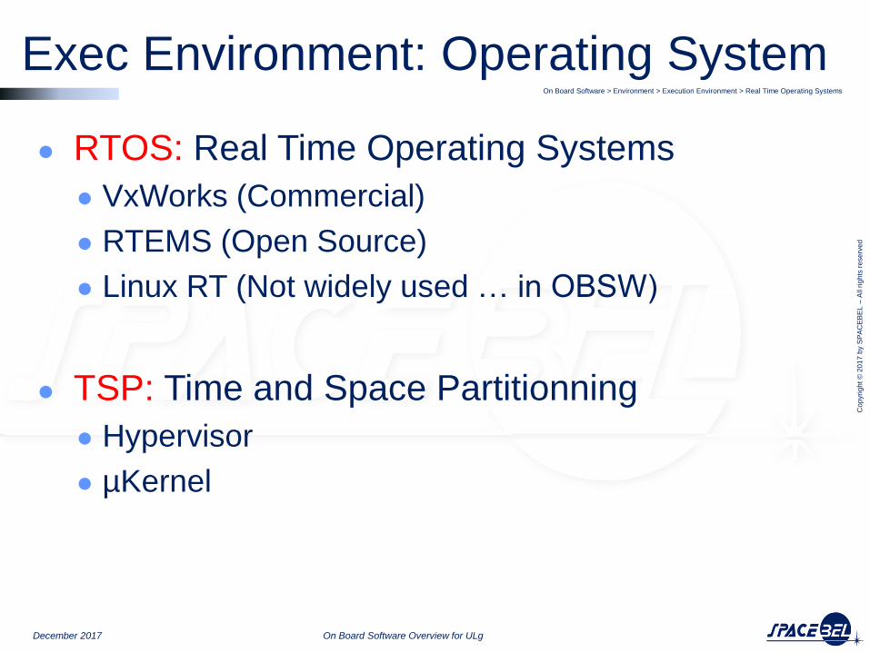
● RTOS: Real Time Operating Systems
● VxWorks (Commercial)
● RTEMS (Open Source)
● Linux RT (Not widely used … in OBSW)
● TSP: Time and Space Partitionning
● Hypervisor
● µKernel
On Board Software > Environment > Execution Environment > Real Time Operating Systems
December 2017 On Board Software Overview for ULg
Exec Environment: Operating System

Cop
yri
gh
t ©
20
17
by S
PA
CE
BE
L –
All r
igh
ts r
ese
rve
d
December 2017 On Board Software Overview for ULg
● OBSW Characteristics
● OBSW Process
● OBSW Architectures
● OBSW Environments
● OBSW Execution Environment
● OBSW Development Environment
● Modelling
● Programming
● Production
● Validation

Cop
yri
gh
t ©
20
17
by S
PA
CE
BE
L –
All r
igh
ts r
ese
rve
d
December 2017 On Board Software Overview for ULg
● OBSW Characteristics
● OBSW Process
● OBSW Architectures
● OBSW Environments
● OBSW Execution Environment
● OBSW Development Environment
● OBSW Modelling
● OBSW Programming
● OBSW Production
● OBSW Validation

Cop
yri
gh
t ©
20
17
by S
PA
CE
BE
L –
All r
igh
ts r
ese
rve
d
Development Environment: Modeling On Board Software > Environment > Development Environment > Modelling
December 2017 On Board Software Overview for ULg
Software has the rare property that it allows us to directly evolve models into fully-fledged
implementations without changing the engineering medium, tools, or methods
The software model may evolve into the system it was
modeling in a seamless process.
non available
not lockedlocked
buffer ready
link available
not locked
set to unavailable
set to available
locked
start transfer
buffer ready
set to available
set to unavailable
/*! Note: This function is only called from the event manager sporadic activities. * Extraction of the event data is performed within EVTM_execute_sporadic_activities. */ TM_DECLARE_NEW_MESSAGE (TM_room, TM_ptr, TM_FIXED_SIZE + EVT_MAX_EVENT_DATA_LENGTH) uint32 data_size; uint8 * data_ptr = TM_get_data(TM_ptr); /*! Verify event_id input. It must be less than EVT_NB_EVENTS. Note that this only protects from table overflow: * This should indeed never happen as the data has been checked when it was put in the queue. * Therefore only return to avoid overflowing, no report is generated. */ if (event_id >= EVT_NB_EVENTS) { return; } /*! The event must be enabled for reporting: If the event id is disabled, return without generating a report. */ if (EVTR_config[event_id].reported == False) { return; } /*! Event data size is limited by the maximum event length. If the generation of this report would create * a telemetry packet with data size larger than EVT_MAX_EVENT_DATA_LENGTH, truncate to EVT_MAX_EVENT_DATA_LENGTH. */ data_size = sizeof(EVT_RID_t) + event_data_length; if (data_size > EVT_MAX_EVENT_DATA_LENGTH) { data_size = EVT_MAX_EVENT_DATA_LENGTH; } GU_memcpy( data_ptr , &event_id , sizeof(EVT_RID_t) ); data_ptr += sizeof(EVT_RID_t); if (event_data != NULLPTR) { GU_memcpy(data_ptr, event_data, data_size - sizeof(EVT_RID_t)); } /*! Generate the event by creating the corresponding service 5 packet. The PUS subtype (between 1 and 4) * is obtained from the EVTR_config configuration table. */ TM_create(TM_ptr, application_id, TMTC_ERS, EVTR_config[event_id].event_subtype, 0, /* data are already at the correct place */ data_size, ROUTE_GROUND_ID); TM_send_telemetry (TM_ptr, data_size + TM_FIXED_SIZE, True, False);
Cop
yri
gh
t ©
20
17
by S
PA
CE
BE
L –
All r
igh
ts r
ese
rve
d
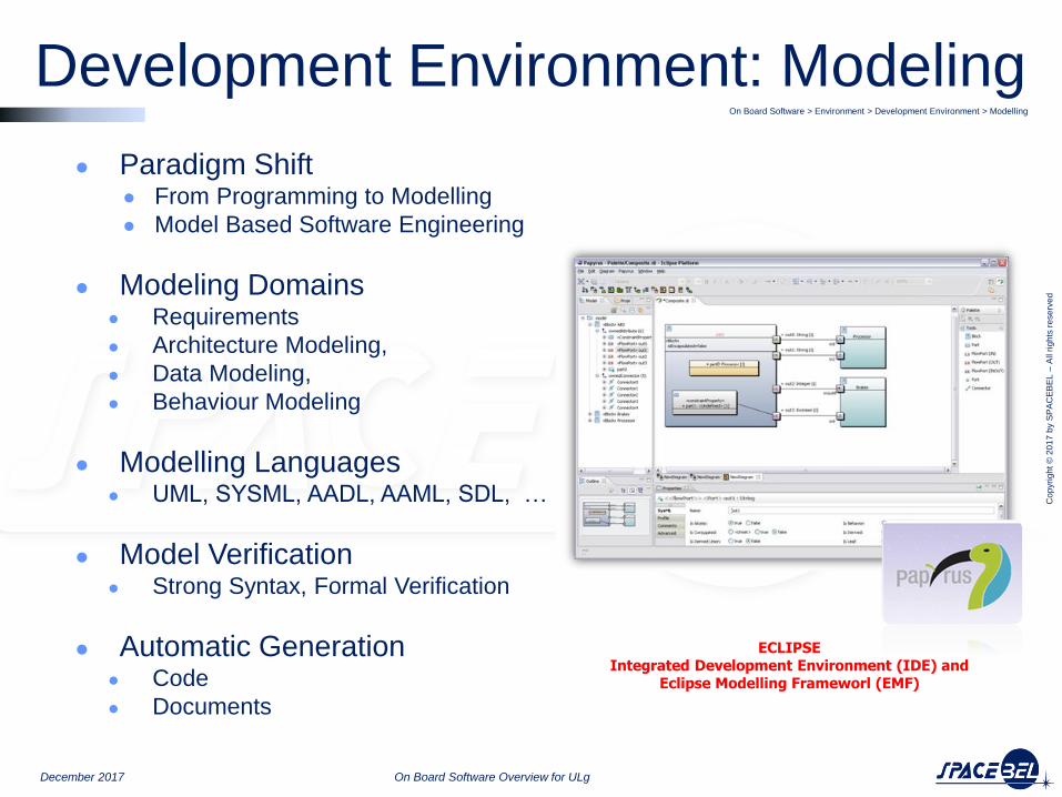
Development Environment: Modeling On Board Software > Environment > Development Environment > Modelling
December 2017 On Board Software Overview for ULg
● Paradigm Shift ● From Programming to Modelling
● Model Based Software Engineering
● Modeling Domains ● Requirements
● Architecture Modeling,
● Data Modeling,
● Behaviour Modeling
● Modelling Languages ● UML, SYSML, AADL, AAML, SDL, …
● Model Verification ● Strong Syntax, Formal Verification
● Automatic Generation ● Code
● Documents
ECLIPSE Integrated Development Environment (IDE) and
Eclipse Modelling Frameworl (EMF)

Cop
yri
gh
t ©
20
17
by S
PA
CE
BE
L –
All r
igh
ts r
ese
rve
d
December 2017 On Board Software Overview for ULg
● OBSW Characteristics
● OBSW Process
● OBSW Architectures
● OBSW Environments
● OBSW Execution Environment
● OBSW Development Environment
● OBSW Modelling
● OBSW Programming
● OBSW Production
● OBSW Validation

Cop
yri
gh
t ©
20
17
by S
PA
CE
BE
L –
All r
igh
ts r
ese
rve
d
● Languages ● C:
procedural language, widely used, poor expressivness but good control, well suited to system programming, efficient code but error prone
● Ada: strong typing, well suited to embedded and real-time programming, mainly used in launchers
● C++ : object oriented, based on C, less efficient due to object oriention, not used or poorly used on board so far
● Java : object oriented, interpreted language, under investigation, possibly for OBCP
● Assembler low level language, for specific usage
On Board Software > Environment > Development Environment > Languages
December 2017 On Board Software Overview for ULg
Development Environment: Programming

Cop
yri
gh
t ©
20
17
by S
PA
CE
BE
L –
All r
igh
ts r
ese
rve
d
December 2017 On Board Software Overview for ULg
● OBSW Characteristics
● OBSW Process
● OBSW Architectures
● OBSW Environments
● OBSW Execution Environment
● OBSW Development Environment
● OBSW Modelling
● OBSW Programming
● OBSW Production
● OBSW Validation
Cop
yri
gh
t ©
20
17
by S
PA
CE
BE
L –
All r
igh
ts r
ese
rve
d
Development Environment: Production On Board Software > Environment > Development Environmernt > Production Tool
December 2017 On Board Software Overview for ULg
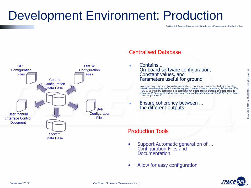
OBSW
Configuration
Files
ODE
Configuration
Files
User Manual Interface Control
Document
System
Data Base
Central
Configuration
Data Base
SVF
Configuration
Files
Production Tools
• Support Automatic generation of … Configuration Files and Documentation
• Allow for easy configuration
Centralised Database ● Contains …
On-board software configuration, Constant values, and Parameters useful for ground tasks, message queues, observable parameters, events, actions associated with events, default housekeeping, default monitoring, patch areas, Drivers commands, TC function ID’s (PUS 8, 1), Memory partitions, File partitions, On-board stores, Default on-board storage allocation, PUS services and sub-services, Types of the parameters in the PUS TC/TM, Error codes, Application ID …
● Ensure coherency between … the different outputs
Cop
yri
gh
t ©
20
17
by S
PA
CE
BE
L –
All r
igh
ts r
ese
rve
d
December 2017 On Board Software Overview for ULg
● OBSW Characteristics
● OBSW Process
● OBSW Architectures
● OBSW Environments
● OBSW Execution Environment
● OBSW Development Environment
● OBSW Modelling
● OBSW Programming
● OBSW Production
● OBSW Validation

Cop
yri
gh
t ©
20
17
by S
PA
CE
BE
L –
All r
igh
ts r
ese
rve
d
Development Environment: Validation On Board Software > Environment > Validation Environment
December 2017 On Board Software Overview for ULg
OBSW
Drivers
Applications
Data Handling Software
RF PWR AOCS
DHS PUS
DHS CORE
SYS MGT
TTM SIM DAM RECU
APP SVC
MPM
OBCP
FDIR
Generic SVF Component
Platform dependent SVF Component
Test Conducting
Sim
ula
tio
n
Co
ntr
ollers
Simulation Core
Environment
Graphical User
Interface
Script Language Interpreter
Integrated Symbolic Debugger
Instruction Set Simulator
Engine
Discrete Event &Time
Simulator Engine
Ground
Equipments
Communications
Memory Simulation
Marker/ Breakpoints/
Coverage
Processor Registers Simulation
ST GPS MM RW MT
SIM DAM RECU TTM
Instrum LYRA Distributed Simulation Interface
Configuration
Calibration
Test Conducting Script
Message Parsing &
Formatting
Synchro- nisation
MPM
RWM
Mu
lti
Co
ntr
ollers S
up
po
rt

Cop
yri
gh
t ©
20
17
by S
PA
CE
BE
L –
All r
igh
ts r
ese
rve
d
OBSW
Modelling
December 2017 On Board Software Overview for ULg
Cop
yri
gh
t ©
20
17
by S
PA
CE
BE
L –
All r
igh
ts r
ese
rve
d
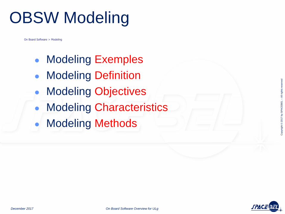
● Modeling Exemples
● Modeling Definition
● Modeling Objectives
● Modeling Characteristics
● Modeling Methods
December 2017 On Board Software Overview for ULg
OBSW Modeling On Board Software > Modeling

Cop
yri
gh
t ©
20
17
by S
PA
CE
BE
L –
All r
igh
ts r
ese
rve
d
Modeling : Examples
December 2017 On Board Software Overview for ULg
On Board Software > Modeling > Examples
Software has the rare property that it allows us to directly evolve models into fully-fledged
implementations without changing the engineering medium, tools, or methods
The software model may evolve into the system it was
modeling in a seamless process.
non available
not lockedlocked
buffer ready
link available
not locked
set to unavailable
set to available
locked
start transfer
buffer ready
set to available
set to unavailable
/*! Note: This function is only called from the event manager sporadic activities. * Extraction of the event data is performed within EVTM_execute_sporadic_activities. */ TM_DECLARE_NEW_MESSAGE (TM_room, TM_ptr, TM_FIXED_SIZE + EVT_MAX_EVENT_DATA_LENGTH) uint32 data_size; uint8 * data_ptr = TM_get_data(TM_ptr); /*! Verify event_id input. It must be less than EVT_NB_EVENTS. Note that this only protects from table overflow: * This should indeed never happen as the data has been checked when it was put in the queue. * Therefore only return to avoid overflowing, no report is generated. */ if (event_id >= EVT_NB_EVENTS) { return; } /*! The event must be enabled for reporting: If the event id is disabled, return without generating a report. */ if (EVTR_config[event_id].reported == False) { return; } /*! Event data size is limited by the maximum event length. If the generation of this report would create * a telemetry packet with data size larger than EVT_MAX_EVENT_DATA_LENGTH, truncate to EVT_MAX_EVENT_DATA_LENGTH. */ data_size = sizeof(EVT_RID_t) + event_data_length; if (data_size > EVT_MAX_EVENT_DATA_LENGTH) { data_size = EVT_MAX_EVENT_DATA_LENGTH; } GU_memcpy( data_ptr , &event_id , sizeof(EVT_RID_t) ); data_ptr += sizeof(EVT_RID_t); if (event_data != NULLPTR) { GU_memcpy(data_ptr, event_data, data_size - sizeof(EVT_RID_t)); } /*! Generate the event by creating the corresponding service 5 packet. The PUS subtype (between 1 and 4) * is obtained from the EVTR_config configuration table. */ TM_create(TM_ptr, application_id, TMTC_ERS, EVTR_config[event_id].event_subtype, 0, /* data are already at the correct place */ data_size, ROUTE_GROUND_ID); TM_send_telemetry (TM_ptr, data_size + TM_FIXED_SIZE, True, False);
Cop
yri
gh
t ©
20
17
by S
PA
CE
BE
L –
All r
igh
ts r
ese
rve
d
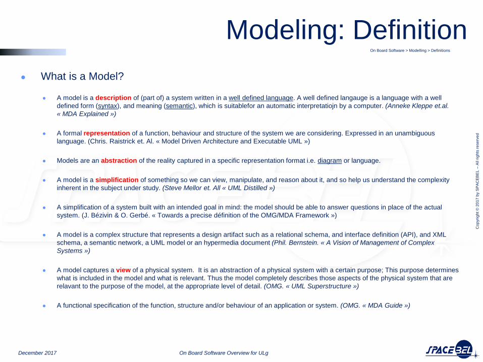
● What is a Model?
● A model is a description of (part of) a system written in a well defined language. A well defined langauge is a language with a well
defined form (syntax), and meaning (semantic), which is suitablefor an automatic interpretatiojn by a computer. (Anneke Kleppe et.al.
« MDA Explained »)
● A formal representation of a function, behaviour and structure of the system we are considering. Expressed in an unambiguous
language. (Chris. Raistrick et. Al. « Model Driven Architecture and Executable UML »)
● Models are an abstraction of the reality captured in a specific representation format i.e. diagram or language.
● A model is a simplification of something so we can view, manipulate, and reason about it, and so help us understand the complexity
inherent in the subject under study. (Steve Mellor et. All « UML Distilled »)
● A simplification of a system built with an intended goal in mind: the model should be able to answer questions in place of the actual
system. (J. Bézivin & O. Gerbé. « Towards a precise définition of the OMG/MDA Framework »)
● A model is a complex structure that represents a design artifact such as a relational schema, and interface definition (API), and XML
schema, a semantic network, a UML model or an hypermedia document (Phil. Bernstein. « A Vision of Management of Complex
Systems »)
● A model captures a view of a physical system. It is an abstraction of a physical system with a certain purpose; This purpose determines
what is included in the model and what is relevant. Thus the model completely describes those aspects of the physical system that are
relavant to the purpose of the model, at the appropriate level of detail. (OMG. « UML Superstructure »)
● A functional specification of the function, structure and/or behaviour of an application or system. (OMG. « MDA Guide »)
On Board Software > Modelling > Definitions
December 2017 On Board Software Overview for ULg
Modeling: Definition

Cop
yri
gh
t ©
20
17
by S
PA
CE
BE
L –
All r
igh
ts r
ese
rve
d
●Objectives of Software Modeling ● To deal with complexity of systems development through
● Abstraction:
Abstract a problem to focus on some particular points of interest and to improve
understandability of a problem
• Iteration:
Iterative modeling may be expressed at different level of fidelity
• Separation of Concerns:
Possible set of nearly independent views of a model (“Aspect Oriented Modeling”)
• Domain Specific Language:
To focus on specific domain expertise
• To minimize development risks through
• Through analysis and experimentation performed earlier in the design cycle
• Enable to investigate and compare alternative solutions
● To improve communication ...
• to foster information sharing and reuse!
A model is often best suited than a long speech !
On Board Software > Modellling > Objectives
December 2017 On Board Software Overview for ULg
Modeling: Objectives

Cop
yri
gh
t ©
20
17
by S
PA
CE
BE
L –
All r
igh
ts r
ese
rve
d
● Characteristics of Useful Models:
● Abstract
● Emphasize important aspects while removing irrelevant ones
● Understandable
● Expressed in a form that is readily understood by observers
● Accurate
● Faithfully represents the modeled system
● Predictive
● Can be used to answer questions about the modeled system
● Inexpensive
● Much cheaper to construct and study than the modeled system
On Board Software > Modellling > Characteristics
December 2017 On Board Software Overview for ULg
Modeling: Characteristics
To be useful, engineering models must satisfy all of these characteristics!

Cop
yri
gh
t ©
20
17
by S
PA
CE
BE
L –
All r
igh
ts r
ese
rve
d
● In an attempt to formalize more and more the expression of the software documentation and production, the design, architecture and requirements have moved from simple text to drawings and from drawings to models.
With the emergence of new tools these model representations can be constructed, translated and exploited in different ways:
● Analysis: various types of model checking e.g. completeness and consistency analysis
● Simulation: execution of model, behavior can be simulated
● Design: decomposition of system in smaller components, establishing interfaces
● Coding: automatic generation of source code e.g. C or Ada (auto-coding)
● Testing: automatic generation of tests (auto-testing)
● Proving: formal verification or proof
On Board Software > Modeling > Usage
December 2017 On Board Software Overview for ULg
Modeling: Usage
Cop
yri
gh
t ©
20
17
by S
PA
CE
BE
L –
All r
igh
ts r
ese
rve
d
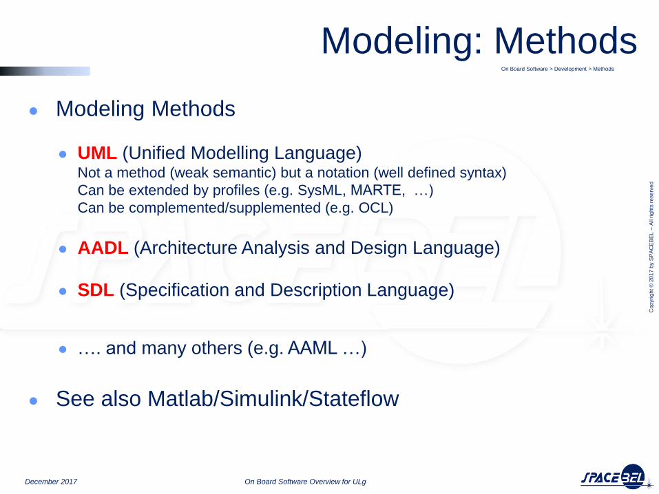
● Modeling Methods
● UML (Unified Modelling Language) Not a method (weak semantic) but a notation (well defined syntax)
Can be extended by profiles (e.g. SysML, MARTE, …)
Can be complemented/supplemented (e.g. OCL)
● AADL (Architecture Analysis and Design Language)
● SDL (Specification and Description Language)
● …. and many others (e.g. AAML …)
● See also Matlab/Simulink/Stateflow
On Board Software > Development > Methods
December 2017 On Board Software Overview for ULg
Modeling: Methods

Cop
yri
gh
t ©
20
17
by S
PA
CE
BE
L –
All r
igh
ts r
ese
rve
d
Use Case Diagram
December 2017 On Board Software Overview for ULg
CFDP manager
Communication system
send and receive PDUs
to and from remote
CFDP entities
PUS services
configure, control and
monitor CFDP
transactions
perform high-level
operations on the
distributed CFDP
file-system
transfer PUS
messages to a
remote SC
onboard applicationonboard application
local CFDP entitylocal CFDP entity
local file systemlocal file system
remote CFDP entityremote CFDP entityremote file system
space linkspace link
inter spacecraft linkinter spacecraft link
local CFDP entitylocal CFDP entity
On Board Software > Modeling > UML > Use Case Diagram
Cop
yri
gh
t ©
20
17
by S
PA
CE
BE
L –
All r
igh
ts r
ese
rve
d
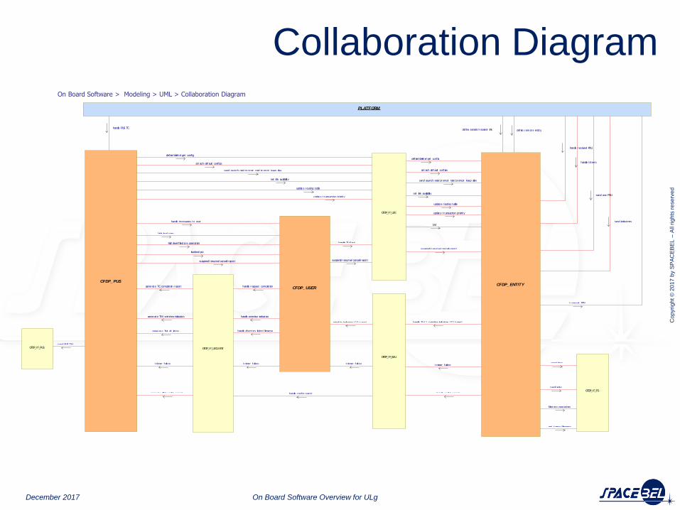
Collaboration Diagram
December 2017 On Board Software Overview for ULg
CFDP_ENTITYCFDP_PUS
CFDP_IF_U2E
def ine/delet e/ get conf ig
at t ach def ault conf igs
send asynch nak/ prompt nak/ prompt keep alive
set link availability
updat e rout ing table
def ine/delet e/ get conf ig
at t ach def ault conf igs
send asynch nak/ prompt nak/ prompt keep alive
set link availability
updat e rout ing table
suspend/resume/ cancel/ repor t
put
updat e t ransact ion priorit y
updat e t ransact ion priorit y
PLATFORM
handle PUS TC
handle received PDU
handle t imers
send one PDU
send indicat ions
def ine sender /receiver link def ine remot e ent it y
t ransmit PDU
CFDP_IF_PUSsend PUS TM
CFDP_USER
high level copy
low- level put
suspend/resume/ cancel/ repor t
handle TLV/ put
suspend/resume/ cancel/ repor t
high level f ilest ore operat ion
handle messages to user
CFDP_IF_U2CLIENT
handle request complet ion
handle primit ive indicat ion
handle directory list ing f ilename
generat e TC complet ion repor t
generat e TM primit ive indicat ion
generat e TM dir list ing
generat e TM conf ig report
t rigger failuret rigger failure
CFDP_IF_E2U
primit ive indicat ion (12 t ypes)
handle conf ig report
handle TLV / pr imit ive indicat ion (12 types)
handle conf ig report
t rigger failuret rigger failure
CFDP_IF_FS
open/ close
read/ wr ite
f ilestore operat ions
get t emp f ilename
On Board Software > Modeling > UML > Collaboration Diagram

Cop
yri
gh
t ©
20
17
by S
PA
CE
BE
L –
All r
igh
ts r
ese
rve
d
Class Diagram
December 2017 On Board Software Overview for ULg
On Board Software > Modeling > UML > Class Diagram
Cop
yri
gh
t ©
20
17
by S
PA
CE
BE
L –
All r
igh
ts r
ese
rve
d
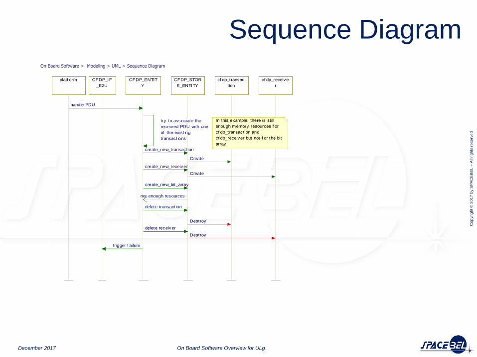
Sequence Diagram
December 2017 On Board Software Overview for ULg
CFDP_ENTIT
Y
try to associate the
received PDU with one
of the exist ing
transact ions
platf orm
handle PDU
cf dp_transac
tion
cf dp_receive
r
CFDP_STOR
E_ENTITY
Create
create_new_bit_array
not enough resources
Destroy
Destroy
create_new_transaction
create_new_receiver
delete transact ion
delete receiver
Create
CFDP_IF
_E2U
trigger f ailure
In this example, there is still
enough memory resources f or
cf dp_transaction and
cf dp_receiver but not f or the bit
array.
On Board Software > Modeling > UML > Sequence Diagram

Cop
yri
gh
t ©
20
17
by S
PA
CE
BE
L –
All r
igh
ts r
ese
rve
d
State Diagram
December 2017 On Board Software Overview for ULg
non available
not lockedlocked
buffer ready
link available
not locked
set to unavailable
set to available
locked
start transfer
buffer ready
set to available
set to unavailable
stopped
started
suspendedrunning
start
suspend
resume
start
f ired
delay elapsedstart
stop
On Board Software > Modeling > UML > State Diagram

Cop
yri
gh
t ©
20
17
by S
PA
CE
BE
L –
All r
igh
ts r
ese
rve
d
OBSW
On Board Control Procedures
December 2017 On Board Software Overview for ULg

Cop
yri
gh
t ©
20
17
by S
PA
CE
BE
L –
All r
igh
ts r
ese
rve
d
● On Board Control Procedures (OBCPs) are flight procedures written in a high level language.
● These are pieces of software that can be resident on board or that can be uploaded to the spacecraft as required by ground,
● to be interpreted and executed on board, on demand, at any time and
● that may interact, to different extents, with the rest of the data handling system.
● They differ from native applicative components in that their invocation and execution may be controlled. This concerns in particular the ability to suspend or abort their execution.
What are OBCPs?
December 2017 On Board Software Overview for ULg
Cop
yri
gh
t ©
20
17
by S
PA
CE
BE
L –
All r
igh
ts r
ese
rve
d
● OBCPs provide a flexible way to operate the spacecraft, to extend the on board software functionality or to modify the behaviour of on board applications, even in flight.
● OBCPs participate to on board autonomy when a rapid reaction is needed in spite of reduced spacecraft visibility or long propagation delay.
● Trend is to have generic functions implemented in the FSW and mission specific functions in OBCPs
Why OBCPs?
December 2017 On Board Software Overview for ULg

Cop
yri
gh
t ©
20
17
by S
PA
CE
BE
L –
All r
igh
ts r
ese
rve
d
What are OBCP Used For?
Type Applications Interaction User
OBOP
On Board
Operation
Procedures
Command
Sequences
- On Board Execution of Ground Procedures,
- End-of-Life Operations
Limited to
- Telecommand
- Telemetry
- Event
OP
Engineer
- Mode Management,
- Configuration Sequences,
- Recovery Procedures
PF or PL
Engineer
- Support to Assembly Integration and Testing
- Long and complex configuration sequences
- Fault injection and robustness testing
- Temporary functions for testing purposes
AIT
Engineer
OBAP
On Board
Application
Procedures
High Level
Script
Extended to
- Data Pool
- Equipments
- Drivers
- Simple On Board Applications
- Mission Specific Functions
- Accomodation of Late Definition
PF or PL
Engineer
- Debugging
- Short Term Work Around Solutions
- On Board Patches
- Adaptation to unpredictable environment
OBSW
Engineer
December 2017 On Board Software Overview for ULg

Cop
yri
gh
t ©
20
17
by S
PA
CE
BE
L –
All r
igh
ts r
ese
rve
d
How do OBCPs work?
OBCPs are first prepared on ground The preparation on ground relies on an environment composed amongst others of an editor, a compiler and, ideally, a debugger. The OBCPs are written in a high level user language. They are first compiled and linked on ground to yield an intermediate byte code that can efficiently be uploaded and interpreted on board.
OBCPs are uploaded on board by ground The intermediate byte code is uploaded via appropriate telecommands and is stored on board.
OBCPs are executed on board. The execution on board relies on virtual machine that interprets the instructions and interacts with the rest of the On Board Software while also providing some kind of time and in space isolation for fault containment.
OBCP
Ground
Preparation
Environment
OBCP
On Board
Execution
Environment
OBCP
User
Language
OBCP
Intermediate
Byte Code
OBCP
Intermediate
Byte Code
December 2017 On Board Software Overview for ULg

Cop
yri
gh
t ©
20
17
by S
PA
CE
BE
L –
All r
igh
ts r
ese
rve
d
OBCP Overall Architecture
OBCP
Ground
Preparation
Environment
OBCP
On Board
Execution
Environment
OBCP
User
Language
OBCP
Intermediate
Byte Code
OBCP
Ground
Debugger
Environment
December 2017 On Board Software Overview for ULg
Cop
yri
gh
t ©
20
17
by S
PA
CE
BE
L –
All r
igh
ts r
ese
rve
d
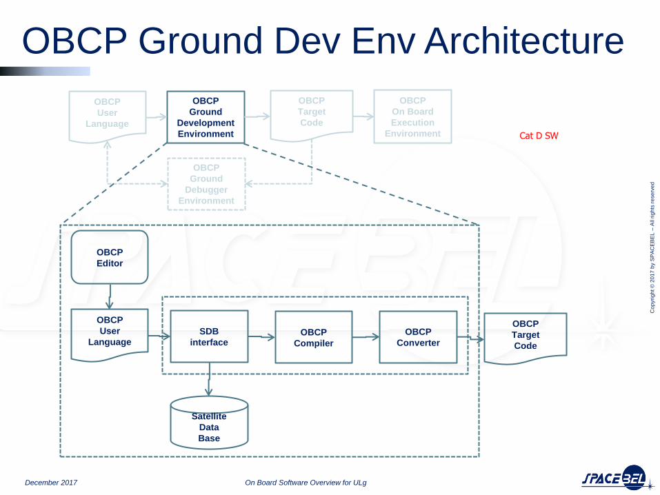
OBCP Ground Dev Env Architecture
OBCP
Ground
Development
Environment
OBCP
On Board
Execution
Environment
OBCP
User
Language
OBCP
Target
Code
OBCP
Ground
Debugger
Environment
SDB
interface
OBCP
User
Language
OBCP
Target
Code
OBCP
Editor
OBCP
Compiler
OBCP
Converter
Satellite
Data
Base
Cat D SW
December 2017 On Board Software Overview for ULg

Cop
yri
gh
t ©
20
17
by S
PA
CE
BE
L –
All r
igh
ts r
ese
rve
d
OBCP OB Exec Env Architecture
OBCP
Manager
OBCP
Target
Code
OBCP
Interpreter
OBSW
Interface
OBCP
Scheduler
On Board Software
OBCP
Ground
Development
Environment
OBCP
On Board
Execution
Environment
OBCP
User
Language
OBCP
Target
Code
OBCP
Ground
Debugger
Environment
Cat C/B SW
December 2017 On Board Software Overview for ULg

Cop
yri
gh
t ©
20
17
by S
PA
CE
BE
L –
All r
igh
ts r
ese
rve
d
OBCP Ground Debug Env Archi
OBCP
Ground
Development
Environment
OBCP
On Board
Execution
Environment
OBCP
User
Language
OBCP
Target
Code
OBCP
Ground
Debugger
Environment
OBCP
Target
Code
OBCP
Interpreter
OBSW
Interface
OBSW
Stubs
OBCP
Debugger
Cat D SW
December 2017 On Board Software Overview for ULg
Cop
yri
gh
t ©
20
17
by S
PA
CE
BE
L –
All r
igh
ts r
ese
rve
d
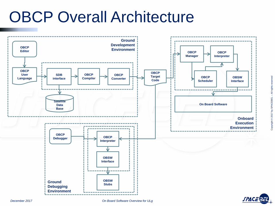
OBCP Overall Architecture
SDB
interface
OBCP
User
Language
OBCP
Editor
OBCP
Compiler OBCP
Converter
Satellite
Data
Base
Ground
Development
Environment
Onboard
Execution
Environment
OBCP
Manager
OBCP
Target
Code
OBCP
Interpreter
OBSW
Interface
OBCP
Scheduler
On Board Software
OBCP
Interpreter
OBSW
Interface
OBSW
Stubs
OBCP
Debugger
Ground
Debugging
Environment
December 2017 On Board Software Overview for ULg