SpaceClaim User’s Guidesp6.spaceclaim.com/guide/SpaceClaim2007UsersGuide.pdf · SpaceClaim User's...
99
A SPACECLAIM Document SpaceClaim User’s Guide Version 2007
Transcript of SpaceClaim User’s Guidesp6.spaceclaim.com/guide/SpaceClaim2007UsersGuide.pdf · SpaceClaim User's...

A SPACECLAIM Document
SpaceClaim User’s GuideVersion 2007

Copyright © 2007 SpaceClaim Corporation. All Rights Reserved. SpaceClaim is a registered trademark of SpaceClaim Corporation. Anti-Grain Geometry Version 2.4 Copyright © 2002-2005 Maxim Shemanarev (McSeem). Contains Autodesk® RealDWG by Autodesk, Inc., Copyright © 1998-2006 Autodesk, Inc. All rights reserved. Autodesk, AutoCAD, and Autodesk Inventor are registered trademarks and RealDWG is a trademark of Autodesk, Inc. CATIA is a registered trademark of Dassault Systèmes. Contains DotNetBar licensed from devcomponents.com. 2007 Microsoft ® Office System User Interface is licensed from Microsoft. Direct3D, DirectX, PowerPoint, Windows, Windows Vista and the Windows Vista Start button are trademarks or registered trademarks of Microsoft Corporation in the United States and/or other countries. Portions of this software Copyright © 2005 Novell, Inc. (http://www.novell.com) Contains OpenDWG licensed from the Open Design Alliance. OpenDWG is a trademark of the Open Design Alliance. Pro/ENGINEER and PTC are registered trademarks of Parametric Technology Corporation. SolidWorks is a registered trademark of SolidWorks Corporation. Portions of this software are owned by Spatial Corp. © 1986-2007. All Rights Reserved. ACIS and SAT are registered trademarks of Spatial Corp. TraceParts is owned by TraceParts S.A. TraceParts is a registered trademark of TraceParts S.A. Contains a modified version of source available from Unicode, Inc., copyright © 1991-2007 Unicode, Inc. All rights reserved. Distributed under the Terms of Use in http://www.unicode.org/copyright.html. Portions of this software are owned by Unigraphics Solutions Inc. © 1986-2006. All Rights Reserved. Parasolid and Unigraphics are registered trademarks and JT is a trademark of UGS Corp. All other trademarks, trade names or company names referenced in SpaceClaim software, documentation and promotional materials are used for identification only and are the property of their respective owners.

ii
Table Of Contents Introduction ...........................................................................................................................................1 Getting started .......................................................................................................................................2
Tutorials .............................................................................................................................................2 Creating a flag bracket .....................................................................................................................3
Getting help ........................................................................................................................................8 The SpaceClaim interface.....................................................................................................................9
Designing............................................................................................................................................. 11 Cutting, copying, and pasting............................................................................................................. 11 Detaching in 2D and 3D..................................................................................................................... 12 Undoing and redoing your actions ...................................................................................................... 12 The Move handle............................................................................................................................... 12 Orienting designs .............................................................................................................................. 14
Spinning your design...................................................................................................................... 14 Panning your design....................................................................................................................... 15 Zooming into and out of your design............................................................................................... 15 Rotating your design ...................................................................................................................... 16 Your Home view ............................................................................................................................ 16 Display a head-on view of the sketch grid........................................................................................ 17 Selecting a view............................................................................................................................. 18 Snapping to a view ........................................................................................................................ 18
Sketching.......................................................................................................................................... 20 The sketch grid.............................................................................................................................. 23 Layouts ......................................................................................................................................... 23 Dimensional sketching.................................................................................................................... 24 Points............................................................................................................................................ 26 Lines ............................................................................................................................................. 26 Tangent lines................................................................................................................................. 27 Construction lines .......................................................................................................................... 27 Rectangles..................................................................................................................................... 28 Three-point rectangles ................................................................................................................... 29 Circles ........................................................................................................................................... 29 Three-point circles ......................................................................................................................... 30 Construction circles ........................................................................................................................ 30 Ellipses.......................................................................................................................................... 31 Tangent arcs ................................................................................................................................. 31 Swept arcs .................................................................................................................................... 32 Three-point arcs ............................................................................................................................ 32 Splines .......................................................................................................................................... 33 Splitting lines ................................................................................................................................. 34

Table Of Contents
iii
Trimming lines............................................................................................................................... 34 Offsetting lines .............................................................................................................................. 35 Creating corners ............................................................................................................................ 35 Creating filleted corners ................................................................................................................. 36 Projecting onto the sketch grid ....................................................................................................... 36
Editing.............................................................................................................................................. 37 Editing overview ............................................................................................................................ 37 Selecting ....................................................................................................................................... 38 Editing with the Pull tool................................................................................................................. 40 Moving .......................................................................................................................................... 47 Moving in two dimensions .............................................................................................................. 48 Editing in cross-section................................................................................................................... 49 Filling ............................................................................................................................................ 49 Bending......................................................................................................................................... 50 Editing faces as a blend.................................................................................................................. 50 Power selection.............................................................................................................................. 51
Intersecting ...................................................................................................................................... 53 Merging and splitting...................................................................................................................... 54 Splitting a body.............................................................................................................................. 58 Splitting a face............................................................................................................................... 59 Projecting to a solid ....................................................................................................................... 59
Inserting........................................................................................................................................... 61 Inserting a plane............................................................................................................................ 61 Inserting an axis ............................................................................................................................ 61 Moving the sketch grid ................................................................................................................... 62 Creating a linear or rectangular pattern........................................................................................... 62 Creating a circular or cylindrical pattern........................................................................................... 63 Turning a solid into a shell.............................................................................................................. 63 Creating an offset relationship ........................................................................................................ 65 Creating a mirror relationship ......................................................................................................... 65
Assembling components .................................................................................................................... 67 Inserting components into your design............................................................................................ 67 Aligning components ...................................................................................................................... 67 Centering components ................................................................................................................... 68 Orienting components .................................................................................................................... 68
Measuring......................................................................................................................................... 68 Detailing .............................................................................................................................................. 71
Annotations ...................................................................................................................................... 72 Creating notes ............................................................................................................................... 72 Creating note leaders ..................................................................................................................... 72 Creating dimension annotations ...................................................................................................... 72 Creating geometric tolerance annotations........................................................................................ 73

SpaceClaim User's Guide
iv
Displaying measurements............................................................................................................... 73 Displaying mass properties ............................................................................................................. 74
Drawing sheets ................................................................................................................................. 75 Working with views ........................................................................................................................ 75 Formatting a drawing sheet ............................................................................................................ 76
3D markup........................................................................................................................................ 77 Creating 3D markup slides.............................................................................................................. 77 Displaying changes to dimensions ................................................................................................... 77 Coloring changed faces .................................................................................................................. 78
Displaying your design .......................................................................................................................... 79 Graphics style ................................................................................................................................... 80
Applying a graphics style to your design.......................................................................................... 80 Displaying edges............................................................................................................................ 80 Applying colors to your design ........................................................................................................ 80
Layers .............................................................................................................................................. 82 Working with layers ....................................................................................................................... 82
Workspace windows .......................................................................................................................... 83 Displaying your design in multiple windows .....................................................................................83 Splitting the workspace window ...................................................................................................... 83 Switching between windows in the workspace .................................................................................83
Displaying workspace tools ................................................................................................................ 83 Working with SpaceClaim documents..................................................................................................... 85
Designs, drawing sheets, and 3D markup ........................................................................................... 85 Opening, importing, and exporting designs, drawing sheets, and 3D markups....................................... 86 Journals............................................................................................................................................ 87 Design structure................................................................................................................................ 87
Customizing SpaceClaim........................................................................................................................ 89 Optimizing graphics and performance................................................................................................. 89 Setting the color scheme ................................................................................................................... 89 Changing the default units ................................................................................................................. 89 Modifying the sketch grid................................................................................................................... 90 Displaying workspace tools ................................................................................................................ 90 Setting advanced options................................................................................................................... 90 Setting detailing options .................................................................................................................... 92 Changing the language...................................................................................................................... 93 Setting snapping options.................................................................................................................... 93 Setting file paths ............................................................................................................................... 93 Customizing the ribbon and Quick Access toolbar ................................................................................93 Configuring SpaceClaim windows ....................................................................................................... 94

1
Introduction SpaceClaim Professional 2007 is the 3D productivity tool for engineers who need to focus on their core competencies while also benefiting from working in 3D. The software provides a highly flexible design environment coupled with a modern user experience that speeds contributions to the product development process. SpaceClaim Professional 2007 is for those who collaborate in the design and manufacture of mechanical products across a broad range of industries.
The online help, tutorials, and training materials are provided to help you become productive with SpaceClaim as quickly as possible. We strongly recommend that you review the Getting Started section and step through the tutorial provided in the online help before beginning your own work. Additional self-paced tutorial videos are available on MySpaceClaim.com. You can also begin by exploring a library of SpaceClaim models.
User's Guide
This User's Guide begins with a focus on the basics and on simple concepts. SpaceClaim is all about adding and manipulating the faces of a design model, primarily through pull and move operations. If there is a face, you can pull on it. If you need a new face, draw an edge or copy an existing one. Design clutter is minimized wherever possible. This guide communicates these simple, but powerful concepts so that you can extrapolate them to your real-world designs. This guide also provides useful shortcuts to use as you progress, and animations of tools in action to help you understand their function.
SpaceClaim is different, and we encourage you to open your mind and enter into a world where you can focus on the design, not the software. SpaceClaim appreciates your feedback, so let us know where we have succeeded and what we can do better. Thanks for your purchase and we look forward to working with you!
Get started using SpaceClaim
1 Sketch and pull to create a part, or open an existing model from any modeling software.
2 Edit the part using SpaceClaim's 2D and 3D editing tools.
3 (Optional) Customize SpaceClaim and your workspace to your working style.
4 Detail the part with notes, measurements, and geometric tolerances.
5 Submit the part for review using 3D Markup.
Watch tutorials
Review demos in the example gallery

2
Getting started
Tutorials The following tutorials provide instructions so that you can follow along with the animation step-by-step. The animated tutorials are displayed in a separate window, and require internet access. The movies will pause to allow you to perform the steps in SpaceClaim before continuing with the animation. The text tutorials are located within this help file. Working through each of these tutorials will allow you to quickly grasp the basics of using all the features available in SpaceClaim.
Self-paced training tutorials
Self-paced, animated training tutorials are available on MySpaceClaim.com, a personalized web portal for easy access to everything SpaceClaim. It provides the ability to:
Gain access through a unique user name and password
Directly download SpaceClaim software, including purchased new products, updates, and upgrades
Search the product knowledge base for answers to common questions
Learn form self-paced training tutorials
Check on the status of your license
Submit a new idea to influence product development
Find the status of outstanding issues
To access MySpaceClaim.com, select the Login link at the top of the SpaceClaim.com home page.

Getting started
3
Creating a flag bracket
In this tutorial, you will use SpaceClaim's sketching and 3D editing tools to create a flagpole bracket like this one:
Please note that as you move back and forth between this help window and the SpaceClaim application, you may need to click once in SpaceClaim to make it the active window before continuing with the directions in the tutorial.
1 Select New > New Design from the Application menu to create a new design.
2 Set the units for the new design.
a Select SpaceClaim Options from the Application menu to display the Popular options.
b Click Units to display the unit settings.
c Set the units to inches as shown in the image. Then click OK.
d Click Grid Settings to modify the sketch grid units to match.
e Set the units for the major and minor grid squares, as shown in the image. Then click OK.
f Click OK on the SpaceClaim Options window to apply the settings to your new design.
3 Create a sketch of the bracket.

SpaceClaim User's Guide
4
a Select the Rectangle tool in the Sketch ribbon group. Then click and drag to create a 1/4" x 3 1/2" rectangle. This rectangle will become the back of the bracket.
b Click Plan View in the Orient ribbon group to view the sketch head-on.
c Sketch a circle whose center is offset from the top rectangle by 2 1/4". This circle will become the outside of the cylinder that holds the flagpole.
Select the Circle tool in the Sketch ribbon group. Hover the mouse over the midpoint of the bottom side, and press Shift. Move your mouse straight down to see the dimension. Type 2.25 and press Enter to set the center point. Now click any point that is 1" away from the center.
d Sketch the inside of the cylinder.
Click the center of the first circle, and click again to set the diameter to 1/2".
e Sketch the bracket walls.
Click the Tangent Line tool in the Sketch ribbon group. Then click the outer circle and click again on the rectangle. Create another tangent line the same way.
f Click in the Quick Access toolbar to save your design.
4 Pull the bracket sketch into 3D.
a Click the Pull tool in the Edit ribbon group. Notice that the sketch is now displayed in a trimetric view as a set of surface regions and edges.
b Create the back of the bracket.
Click the rectangular surface. Pull the surface up. (Your mouse does not need to be on the Pull arrow to pull the surface.) Press the spacebar while you are pulling, enter 2 7/8 and press Enter to dimension the top of the bracket.
c Create the walls of the bracket.
Click the first edge and Ctrl+click the second edge to select both edges.
Click the Pull Direction tool guide to orient the Pull arrow in the right direction. Pull the walls of the bracket almost as high as the rectangular top. Click off the design to de-select the edges. Now, thicken each wall by clicking the wall surface and pulling it to 0.3".
d Create the flagpole holder.
Select the circle surface that will become a hollow cylinder. Click the Up To Body tool guide , then click the top of the rectangular solid to pull the cylinder to the same height.
e Click in the Quick Access toolbar to save your design.
If you have difficulty viewing all of your design, click the Home tool to display a trimetric view of your design centered in the Design window.
5 View your design.
Select the Spin tool from the Orient ribbon group. Click the interior edge of the cylinder and drag to spin your design until you have a view down the cylinder.
6 Clean up your design.
a Trim the excess pieces from inside the cylinder.
Select the Split Body tool from the Intersect ribbon group. Click the interior face of the cylinder. Mouse over your design until the extra pieces of wall that are visible within the cylinder are
Getting started
5
highlighted in red. Click the red piece to remove it. If one of the pieces is hidden, mouse over the location of the piece, and use the scroll wheel to cycle through the hidden solids until you have highlighted the piece you want to trim.
b Remove the extraneous surface.
Your Structure window should now have a tree that looks something like this:
Mouse over each surface until the one that covers the interior of the cylinder is highlighted. Right-click that surface in the tree and select Delete.
7 Edit your design.
a Angle the walls of the bracket.
Select the Move tool in the Edit ribbon group. Click the front surface of the first wall and Ctrl+click the front surface of the second wall. Click the red rotational axis of the Move handle and rotate the front surfaces of the walls.
b Move and thicken the bottom wall of the bracket.
Click the surface in the Structure tree. Select the axis of the Move handle that points toward the top of the bracket and move the surface up a little from the bottom of the bracket. Thicken the bottom wall with the Pull tool.
c Remove the excess material on the back of the bracket.
Select the front surface of the back of the bracket between the two walls. Pull the surface towards the back of the bracket until it is removed. Spin the bracket so that you can see the bottom side. Select the surface between the two walls and pull to remove that excess material as well.
d Create bolt holes on the back of the bracket.
Select Back from the View tool in the Orient ribbon group to display the back of the bracket.
Select the Construction Line tool in the Sketch ribbon group and click the back surface of the bracket to display the sketch grid on that plane. Click and drag to draw the line down the center of the bracket from top to bottom. Right-click the line and select Set As Mirror Line from the context menu.
Select the Circle tool in the Sketch ribbon group and draw two bolt holes of the same diameter on the left side of the mirror line. Notice that they are created on the other side of the mirror for you.
Now click the Pull tool. Hold down the middle mouse button and drag to rotate the view a little bit. Select the circular surfaces you just created and pull them through the back of the bracket to make them into holes. Notice that the same action is performed on the mirrored surfaces.
e Round the edges.
Click and Ctrl+click to select the four edges that define the top and bottom corners of the back of the bracket. Pull the edge towards the center to round the corners.
f Click in the Quick Access toolbar to save your design.
8 Create the flag pole.
a Sketch and pull to create the flag pole solid.

SpaceClaim User's Guide
6
Select Bottom from the View tool in the Orient ribbon group. Select the Circle tool from the Sketch ribbon group. Click the bottom of the bracket to display the sketch grid on the same plane as the bottom of the bracket. Click and drag to draw a half-inch diameter circle to one side of the bracket. Notice that when the diameter of the circle is the same as the inside of the cylinder on the bracket, that the edge of the cylinder highlights in green.
Now select the Pull tool from the Edit ribbon group. Click the Home tool in the Orient ribbon group, and select the circular surface you just drew. Pull it up until it is long enough to represent the base of the flag pole.
b Designate the bracket and flagpole as separate components.
In the Structure window, right-click the design and select Create New Component. Right-click, select Rename, and rename the component Bracket. Mouse over the two solids in the tree until you know which one is the bracket solid. Then click and drag that solid under the new Bracket component in the Structure tree. Repeat these steps to create another component called Pole.
Your Structure window should now have a tree that looks something like this:
c Click in the Quick Access toolbar to save your design.
9 Assemble the bracket and flag pole.
a Center the pole inside the cylinder.
Right-click the Bracket component and in the Structure tree
and select Active Part. Then click the Select tool in the Edit ribbon group. Click the axis of the pole and Ctrl+click the axis of the cylinder to select them both. Then click the Center tool in the Assembly ribbon group to move the pole into the hollow center of the cylinder.
b Adjust the amount of the pole shown outside the bracket.
In the Structure window, click the Pole component to select it, then select the Move tool. Click the axis of the Move handle that points the direction you want to move the pole, then drag the mouse to adjust the amount of the pole that is exposed outside the bracket. (You do not have to place the mouse on the Move axis to move the pole.)
c Click in the Quick Access toolbar to save your design.
10 Rotate the cylinder that holds the pole so that it is held out at an angle from the back of the bracket.
a Move the pole temporarily out of the way.
In the Structure window, click the Pole component to select it, then select the Move tool. Click the axis of the Move handle that points the direction you want to move the pole, then drag the mouse to adjust the amount of the pole that is exposed outside the bracket. (You do not have to place the mouse on the Move axis to move the pole.)
b Select the cylinder and pole.
Click the Select tool in the Edit ribbon group. Select all the faces of the cylinder that need to rotate by Ctrl+clicking the top, outside, inside, and outside face of the cylinder on the bottom of the bracket.
Then Ctrl+click to select the two edges of the cylinder that intersect with the walls on the top side of the bracket and select the two edges of the cylinder on the bottom of the bracket.

Getting started
7
c Rotate the cylinder and pole 15 degrees from vertical.
Select the Move tool in the Edit ribbon group to display the Move handle. Click and drag the yellow center of the Move handle toward the bottom of the bracket to set the point around which the cylinder will rotate. Click the rotational axis of the Move handle that will rotate the cylinder away from the back of the bracket and drag. While moving, press the spacebar to type 15 and press Enter to dimension the move. Notice that the pole moves with the cylinder automatically because you aligned their axes.
d Move the pole back into the cylinder.
Click the Pole component in the Structure window to display the Move handle on the pole. Notice that the Move handle is not correctly aligned with the pole. To fix that, click the Anchor tool guide
and click the axis of the cylinder to re-anchor the Move handle. Then click the axis along which you want to move the pole and drag to replace the pole to its original position.
e Click in the Quick Access toolbar to save your design.

SpaceClaim User's Guide
8
Getting help We offer several resources you may find helpful when using SpaceClaim.
Online help
Detailed tooltips are provided for each tool within SpaceClaim. You may find that a careful reading of the tooltip provides all the information you need to use the tool.
If you need more information, click in the tab bar or press F1 while the tooltip is open to display the online help for the tool. The online help provides step-by-step instructions, animations, and examples.
Customer support
SpaceClaim is committed to providing you with every opportunity to communicate directly with us so you benefit by helping us continuously improve our products, services, and build our growing community. We want to help you apply SpaceClaim efficiently to solve your product development problems.
SpaceClaim's annual lease license includes subscription services, so you can be confident that you will always have access to expert technical resources and the latest software. Subscription services provide the latest product releases and upgrades, direct access to SpaceClaim technical resources via phone, email, and chat, and personalized access to our customer portal: MySpaceClaim.com.
To contact customer support: Email: [email protected] Mail: SpaceClaim, 150 Baker Ave Ext., Concord, MA 01742 Toll free phone: 1.800.636.4215 Local/International phone: 1.978.482.2281
Phones are staffed 8:30am - 6pm EST, Monday-Friday, excluding US national holidays
When contacting customer support, the following information may be needed to properly diagnose your issue:
SpaceClaim version number Environment details (operating system, hardware, graphics card) Brief description of your issue Detailed steps to reproduce the issue Related files (journal files, data files)
Gathering this information before contacting customer support could help us find a resolution more quickly.
MySpaceClaim.com
MySpaceClaim.com is a personalized web portal for easy access to everything SpaceClaim. The web portal provides the ability to:
Gain access through a unique user name and password
Directly download SpaceClaim software, including purchased new products, updates, and upgrades
Search the product knowledge base for answers to common questions
Learn form self-paced training tutorials
Check on the status of your license
Submit a new idea to influence product development
Find the status of outstanding issues
To access MySpaceClaim.com, select the Login link at the top of the SpaceClaim.com home page.
To check for models, updates, contact us, or find the version number
1 Select SpaceClaim Options from the Application menu and click Resources.

Getting started
9
2 Click: Get Models to download models from the SpaceClaim model library Check for Updates to check for recent software updates Contact Us to contact us through our website About to find the version number of the SpaceClaim software you are running.
The SpaceClaim interface SpaceClaim’s graphical user interface (GUI) was designed to conform (within reason) to Microsoft Vista standards and contains the toolbars, buttons, and windows associated with a Vista-compliant graphical application.
As a result, only those features of the GUI that relate to performing SpaceClaim-specific tasks are explained in this guide. We assume, for example, that you are familiar with standard Windows conventions, such as dragging a window’s title bar to move the window, or clicking the close button to close the window.
This image shows the major interface elements in the SpaceClaim application:


11
Designing The tools you use for 2D and 3D sketching and editing are found in SpaceClaim's Design tab. With the design tools, you can sketch in 2D, generate and edit solids in 3D, and work with assemblies of solids.
When creating designs, you will use the following tools most often:
Use the Select tool to select 2D or 3D objects in your design for editing. You can select vertices, edges, axes, faces, surfaces, solids, and components in 3D. In 2D, you can select points and lines. You can also use this tool to change the properties of recognized or inferred objects.
Use the Pull tool to offset, extrude, revolve, sweep, draft, and blend faces; and to round or chamfer corner edges.
Use the Move tool to move any single face, surface, solid, or component The behavior of the Move tool changes based on what you have selected. If you select a face, you can pull or draft it. If you select a solid or surface, you can rotate or translate it.
Use the Section tool to edit solids by moving their edges and vertices in cross-section.
Use the Combine tool to merge and split solids and surfaces.
Design tools are grouped into the following Ribbon groups:
Clipboard Cut, copy, and paste 3D objects.
Orient Spin, pan, and zoom your design. You can also select or create a view.
Sketch Create and edit lines, arcs, splines, rectangles, circles, and points in 2D.
Edit Edit 2D and 3D geometry.
Intersect Merge or split solids and faces.
Insert Create relationships between the components in your design.
Assembly Import other components and orient them within your design.
Measure Find lengths, angles, and volumes.
Press and hold Esc to cancel out of any design action that is taking too long.
Cutting, copying, and pasting Select a tool from the Clipboard ribbon panel to cut, copy, or paste any 2D or 3D object. You can use these tools any time, even when you are designing with other 2D or 3D tools.
To cut an object
1 Select the object.
2 Select the Cut tool from the Clipboard ribbon group.
You can also press Ctrl+X or right-click in the Design window and select Cut from the context menu.
To copy an object
1 Select the object.
2 Select the Copy tool from the Clipboard ribbon group.
You can also press Ctrl+C or right-click in the Design window and select Copy from the context menu.
SpaceClaim User's Guide
12
To paste an object
1 Cut or copy the object.
2 Select the Paste tool from the Clipboard ribbon group.
You can also press Ctrl+V or right-click in the Design window and select Paste from the context menu.
Detaching in 2D and 3D You can detach individual pieces of a sketch, or detach objects or faces in 3D.
To detach in 2D
Alt+drag with the Select tool to detach the selected item when sketching. Use the 2D Move tool to detach items and move them.
To detach in 3D
1 Click the Select tool in the Edit ribbon group.
2 If you want to detach an object, Ctrl+click all its faces to select them.
3 Right-click the object and select Detach from the context menu.
Undoing and redoing your actions SpaceClaim stores all your actions from the moment you open the SpaceClaim application until you close it. This includes the use of all tools in all tabs, opening and closing files, and changing settings. Every action is recorded and can be undone and redone.
To undo or redo a tool action
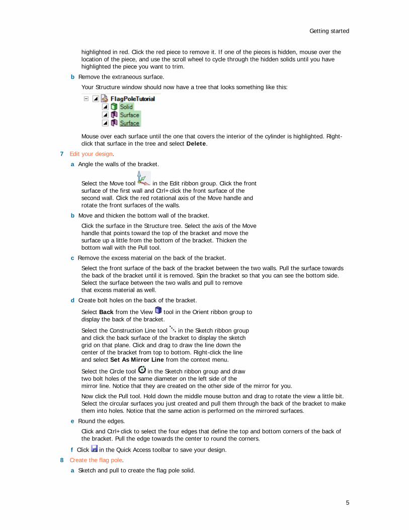
Click the Undo and Redo tools in the Quick Access toolbar or press Ctrl+Z to undo and Ctrl+Y to redo.
You can undo and redo actions until you have undone or redone every action in your session, or you can jump to a particular action by selecting that action from the Undo and Redo menus.
When you undo a tool action, the view is also changed to the view you used to perform that action.
To undo or redo a view
Click the Previous View and Next View tools on the status bar to undo and redo your design view changes.
The Move handle You will use the Move handle to move objects in 2D and 3D. The Move handle allows you to translate and rotate objects. You use the Move handle by clicking the axes of the Move handle and dragging to move the selected object.
When you select the object you want to move, and click one of the Move tools, SpaceClaim guesses at the anchor point and orientation of the Move handle. If either of these is incorrect, you can change them.

Designing
13
To translate objects using the Move handle
1 Click the axis that is aligned with the direction you want to move the selected object.
2 Drag in the direction of the axis to move the object.
To rotate objects using the Move handle
1 Click the rotational axis that is aligned with the direction you want to rotate the selected object.
2 Drag in the direction of the axis to move the object.
To realign the axes of the Move handle
You can realign the Move handle in the following ways:
Drag the small balls on each rotation axis of the Move handle to reorient it. While dragging, you can also press the spacebar to enter the angle directly.
Drag the center ball of the Move handle and place it on another solid, face, edge, or vertex. If you use this method, keep in mind that the selected object is still the one that is going to move.
SpaceClaim User's Guide
14
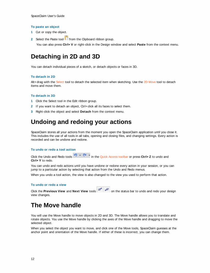
Orienting designs Select a tool from the Orient ribbon group to orient your design in the workspace. You can use these tools at any time, even when you are designing with other 2D or 3D tools.
Do it faster Drag the middle mouse button to spin, Shift+drag it to pan, and Ctrl+drag it to zoom.
Orient ribbon group
The Orient ribbon group contains the following tools:
Use the Home tool to return the orientation of your design to the default, trimetric view. You can customize the Home view to show your design with any orientation, location, and zoom level.
Click the Plan View tool to display a head-on view of the sketch grid.
You can use the Spin tool to re-orient your design in any direction. Spinning your design allows you to view it from any angle.
Use the Pan tool to move your design within the Design window.
Use the Zoom tool to display your design closer or farther away in the Design window. You can zoom the design to fill the Design window, zoom into an area, or zoom in or out a preset amount.
Use the View tool to display a trimetric or isometric view of your design. You can also display a head-on view of the top, bottom, front, back, right, or left side.
Use the Snap View tool to display a head-on view of a face. You can also use the tool to “throw” the highlighted face to the top, bottom, right, or left.
Use the Rotate tool to rotate your design 90 degrees in the plane of the screen. You can rotate your design clockwise or counterclockwise.
Orient modes
When you click the Spin, Pan, and Zoom tools, they stay enabled until you click them again, press Esc, or click another tool.
Undoing and redoing views
You can undo and redo views using the Previous View and Next View tools on the status bar.
Spinning your design
You can use the Spin tool to re-orient your design in any direction. Spinning your design allows you to view it from any angle. SpaceClaim uses standard arc-ball rotation; your design spins as if you could grab it with the cursor and adjust it like a real object.
When you click the Spin tool, it stays enabled until you click it again, press Esc, or click another tool.
Designing
15
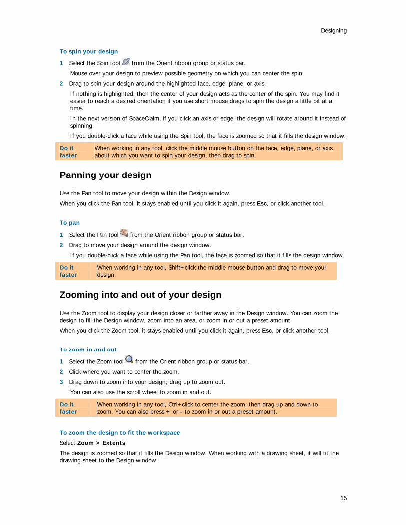
To spin your design
1 Select the Spin tool from the Orient ribbon group or status bar.
Mouse over your design to preview possible geometry on which you can center the spin.
2 Drag to spin your design around the highlighted face, edge, plane, or axis.
If nothing is highlighted, then the center of your design acts as the center of the spin. You may find it easier to reach a desired orientation if you use short mouse drags to spin the design a little bit at a time.
In the next version of SpaceClaim, if you click an axis or edge, the design will rotate around it instead of spinning.
If you double-click a face while using the Spin tool, the face is zoomed so that it fills the design window.
Do it faster
When working in any tool, click the middle mouse button on the face, edge, plane, or axis about which you want to spin your design, then drag to spin.
Panning your design
Use the Pan tool to move your design within the Design window.
When you click the Pan tool, it stays enabled until you click it again, press Esc, or click another tool.
To pan
1 Select the Pan tool from the Orient ribbon group or status bar.
2 Drag to move your design around the design window.
If you double-click a face while using the Pan tool, the face is zoomed so that it fills the design window.
Do it faster
When working in any tool, Shift+click the middle mouse button and drag to move your design.
Zooming into and out of your design
Use the Zoom tool to display your design closer or farther away in the Design window. You can zoom the design to fill the Design window, zoom into an area, or zoom in or out a preset amount.
When you click the Zoom tool, it stays enabled until you click it again, press Esc, or click another tool.
To zoom in and out
1 Select the Zoom tool from the Orient ribbon group or status bar.
2 Click where you want to center the zoom.
3 Drag down to zoom into your design; drag up to zoom out.
You can also use the scroll wheel to zoom in and out.
Do it faster
When working in any tool, Ctrl+click to center the zoom, then drag up and down to zoom. You can also press + or - to zoom in or out a preset amount.
To zoom the design to fit the workspace
Select Zoom > Extents.
The design is zoomed so that it fills the Design window. When working with a drawing sheet, it will fit the drawing sheet to the Design window.

SpaceClaim User's Guide
16
To zoom into a selected area
1 Select Zoom > Zoom Box In.
2 Click and drag to select the area.
Two rectangles appear as you draw. The dotted rectangle shows your selection; the solid rectangle shows what will be displayed in the Design window. When you mouse-up, the design pans and zooms until it fits within the area.
To zoom in and out a preset amount
Select Zoom > Zoom In to bring your design closer. Select Zoom > Zoom Out to move your design further away.
When working in any tool, press + and - to zoom in and out a preset amount.
Rotating your design
Use the Rotate tool to rotate your design 90 degrees in the plane of the screen. You can rotate your design clockwise or counterclockwise.
To rotate your design 90 degrees
Click the Rotate tool .
To change the rotation direction
Select Rotate > Rotate 90 Counterclockwise.
Your design rotates 90 degrees counterclockwise and the Rotate tool icon changes to . Clicking the Rotate tool will continue to rotate in the counterclockwise direction.
Select Rotate > Rotate 90 Clockwise to rotate your design in the clockwise direction and set the Rotate tool to rotate clockwise.
Your Home view
Use the Home tool to return the orientation of your design to the default, trimetric view. You can customize the Home view tool so that it displays your design with a specific orientation, location, and zoom level.
Compared to the isometric view, the trimetric view orients your design so that the front face is angled slightly towards you and less of the top is shown. Compare the two views in the image below.

Designing
17
To display the Home view
Click the Home tool in the Orient ribbon panel.
To customize the Home view
1 Use the other Orient tools to set up a view of your design in the workspace.
2 Select Home > Current-to-Home to make the view in the active Design window the Home view.
Now, when you click the Home tool, your custom view is displayed.
Click Home > Reset Home View to return the Home view to the default, trimetric view.
Display a head-on view of the sketch grid
Click the Plan View tool in the Orient ribbon panel or in the Sketching mini-toolbar to display a head-on view of the sketch grid.
If this tool is disabled, select a plane or planar surface or display the sketch grid.
SpaceClaim User's Guide
18
Selecting a view
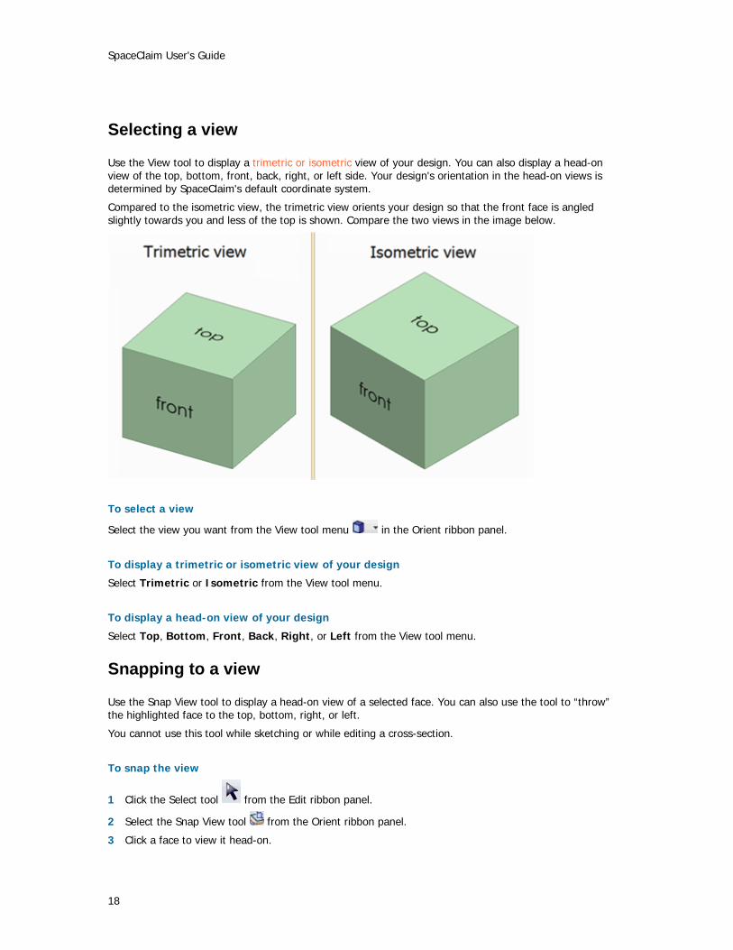
Use the View tool to display a trimetric or isometric view of your design. You can also display a head-on view of the top, bottom, front, back, right, or left side. Your design's orientation in the head-on views is determined by SpaceClaim's default coordinate system.
Compared to the isometric view, the trimetric view orients your design so that the front face is angled slightly towards you and less of the top is shown. Compare the two views in the image below.
To select a view
Select the view you want from the View tool menu in the Orient ribbon panel.
To display a trimetric or isometric view of your design
Select Trimetric or Isometric from the View tool menu.
To display a head-on view of your design
Select Top, Bottom, Front, Back, Right, or Left from the View tool menu.
Snapping to a view
Use the Snap View tool to display a head-on view of a selected face. You can also use the tool to “throw” the highlighted face to the top, bottom, right, or left.
You cannot use this tool while sketching or while editing a cross-section.
To snap the view
1 Click the Select tool from the Edit ribbon panel.
2 Select the Snap View tool from the Orient ribbon panel.
3 Click a face to view it head-on.

Designing
19
4 Click, drag, and release the mouse towards the top, bottom, right, or left side of the design window to “throw” the face to that side.
This gesture will work even with very small mouse movements.
5 Repeat steps 3 and 4 until you see the view you want.
SpaceClaim User's Guide
20
Sketching To use any of the sketch tools to sketch in 2D, you must first display the sketch grid.
Sketching is useful if you want to create a region that can be pulled into 3D. If you want to create a 2D layout, and have no immediate need to generate 3D objects from the lines in the layout, then you should create a layout.
Use the sketch tools to sketch lines in 2D. When you exit the sketch, regions are formed by intersecting lines. These lines will become edges when you pull your sketch into 3D with the Pull tool. Even when pulled into 3D, a region can be decomposed back into its sketched lines for further editing as long as any remnant of the lines is still unused in 3D.
While you are sketching, you may need to orient your design. If you use the Spin, Pan, or Zoom tools to reorient it, click them again or press Esc to continue sketching where you left off.
To sketch
1 Select any sketch tool.
2 Choose where you want to sketch.
3 (Optional) Move or rotate the sketch grid.
4 Draw with the tool.
5 Repeat steps 1 through 4 until you are finished sketching.
Detailed instructions
1 Select any sketch tool from the Sketch ribbon panel.
You can draw points, lines, tangent lines, construction lines, rectangles, three-point rectangles, circles, three-point circles, construction circles, ellipses, splines, tangent arcs, three-point arcs, and sweep arcs using the sketch tools. You can also create sketch lines by projecting the edges of 3D solids onto the sketch grid.
SpaceClaim's sketch tools also let you split, trim, and offset lines, as well as create corners and filleted corners.
2 Choose where you want to sketch.
You can sketch directly on a plane defined by the existing faces or planar surfaces in your design. The sketch grid mini-toolbar allows you to switch from sketching on one plane to sketching on another without leaving the sketch tools.
a If the sketch grid is currently displayed, click Select New Sketch Plane in the mini-toolbar, or right-click and select Select New Sketch Plane from the context menu.
b Mouse over any existing geometry to display existing planes.
c Click to select the highlighted plane and display the sketch grid. Any vertices or edges on the plane are drawn in the current layer color and bolded.
d (Optional) Click Plan View in the mini-toolbar or in the Orient ribbon group to view the sketch grid head-on.
3 (Optional) Move or rotate the sketch grid.
a (Optional) Select any points, lines, or curves that you want to move with the sketch grid.
b Click Move Grid in the mini-toolbar or in the Insert ribbon group.
c Use the manipulator to move or rotate the sketch grid.
4 (Optional) Adjust how solids are displayed while sketching.
Right+click and select:
Clip with Sketch Plane to hide any solids in front of the sketch plane
Designing
21
Fade Scene under Grid to make solids behind the grid appear more faded than the solids in front of the grid
5 Draw with the tool.
Mousing over the sketch grid snaps to points and based on your snapping options. Press Shift to snap to angle increments.
While mousing, SpaceClaim also provides extension lines when you are parallel to an edge or perpendicular to an endpoint. For certain drawing tools, it displays indicators of tangency, line midpoint, line endpoint, squares, and golden rectangles..
All tools let you enter dimensions while sketching. In some tools, you can press Shift at a reference point to see dimensions from that point to the cursor.
When you are done sketching with the tool, you can:
Click another sketching tool.
Click Exit sketch to pull your sketch to 3D.
Press Esc or click the Select tool in the Edit ribbon group to edit the sketch.
To edit a sketch
1 Click the Select tool. (You can also press Esc if you are in a drawing tool.)
2 Click and drag the line or point you want to edit.
Alt+click and drag if you want to detach the line or point before moving it.
Ctrl+drag to create a copy.
To switch from 2D to 3D
Click Exit sketch in the Sketch mini-toolbar or click the Pull tool in the Edit ribbon group.
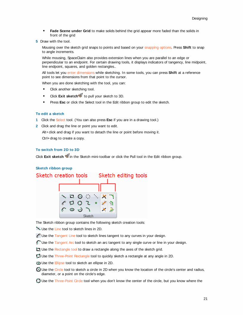
Sketch ribbon group
The Sketch ribbon group contains the following sketch creation tools:
Use the Line tool to sketch lines in 2D.
Use the Tangent Line tool to sketch lines tangent to any curves in your design.
Use the Tangent Arc tool to sketch an arc tangent to any single curve or line in your design.
Use the Rectangle tool to draw a rectangle along the axes of the sketch grid.
Use the Three-Point Rectangle tool to quickly sketch a rectangle at any angle in 2D.
Use the Ellipse tool to sketch an ellipse in 2D.
Use the Circle tool to sketch a circle in 2D when you know the location of the circle's center and radius, diameter, or a point on the circle's edge.
Use the Three-Point Circle tool when you don’t know the center of the circle, but you know where the
SpaceClaim User's Guide
22
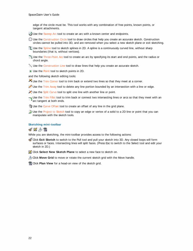
edge of the circle must be. This tool works with any combination of free points, known points, or tangent attachments.
Use the Sweep Arc tool to create an arc with a known center and endpoints.
Use the Construction Circle tool to draw circles that help you create an accurate sketch. Construction circles cannot be pulled into 3D, and are removed when you select a new sketch plane or exit sketching.
Use the Spline tool to sketch splines in 2D. A spline is a continuously curved line, without sharp boundaries (that is, without vertices).
Use the Three-Point Arc tool to create an arc by specifying its start and end points, and the radius or chord angle.
Use the Construction Line tool to draw lines that help you create an accurate sketch.
Use the Point tool to sketch points in 2D.
and the following sketch editing tools:
Use the Trim Corner tool to trim back or extend two lines so that they meet at a corner.
Use the Trim Away tool to delete any line portion bounded by an intersection with a line or edge.
Use the Split Curve tool to split one line with another line or point.
Use the Trim Fillet tool to trim back or connect two intersecting lines or arcs so that they meet with an arc tangent at both ends.
Use the Curve Offset tool to create an offset of any line in the grid plane.
Use the Project to Sketch tool to copy an edge or vertex of a solid to a 2D line or point that you can manipulate with the sketch tools.
Sketching mini-toolbar
While you are sketching, the mini-toolbar provides access to the following actions:
Click Exit Sketch to switch to the Pull tool and pull your sketch into 3D. Any closed loops will form surfaces or faces. Intersecting lines will split faces. (Press Esc to switch to the Select tool and edit your sketch in 2D.)
Click Select New Sketch Plane to select a new face to sketch on.
Click Move Grid to move or rotate the current sketch grid with the Move handle.
Click Plan View for a head-on view of the sketch grid.

Designing
23
The sketch grid
The sketch grid indicates that you are performing actions in a 2D plane. Selection, sketching, creating layouts, adjusting blend planes, cross-section editing, annotating all use the sketch grid.
To display a sketch grid
1 Select any sketch creation tool.
2 Click a face, plane, axis, or drawing sheet.
You can also select the combinations used to insert a plane to display a sketch grid at that location.
To select a new location for the sketch grid
1 click Select New Sketch Plane in the mini-toolbar, or right-click and select Select New Sketch Plane from the context menu.
2 Mouse over any existing geometry to display existing planes.
3 Click to select the highlighted plane and display the sketch grid. Any vertices or edges on the plane are drawn in the current layer color and bolded.
To move the sketch grid
1 (Optional) Select any points, lines, or curves that you want to move with the sketch grid.
2 Click Move Grid in the mini-toolbar or in the Insert ribbon group.
3 Use the Move handle to move or rotate the sketch grid.
To view the sketch grid head-on
Click Plan View in the mini-toolbar or in the Orient ribbon group to view the sketch grid head-on.
To switch from 2D to 3D
Click Exit Sketch in the Sketch mini-toolbar or click the Pull tool in the Edit ribbon group.
Options
You can adjust the units and spacing of the grid, and adjust how solids are displayed when the sketch grid is displayed.
Right+click and select:
Clip with Sketch Plane to hide any solids in front of the sketch plane
Fade Scene under Grid to make solids behind the grid appear more faded than the solids in front of the grid
Layouts
2D layouts are useful when you want to draw in 2D, and have no immediate need to generate 3D objects from the lines in the layout. If you want to create a region that can be pulled into 3D right away, create a sketch instead.
You can think of a layout as a pencil drawing made on your design. If you try to pull layout lines to 3D, they do not behave the same way that sketched lines do. Closed lines are not converted to regions, so if you pull

SpaceClaim User's Guide
24
a layout line, it creates a surface, not a solid. When you are ready to use your layout to create geometry, project the layout lines to a sketch. Projecting a layout line to a sketch is like inking the line.
Layouts always appear on planes in the Structure tree.
We strongly encourage you to use layers when working with layouts to help you organize your design. For example, you can color individual lines on each layout, show or hide the lines, or put the bounding planes on a separate layer and turn that layer's visibility off to declutter your design. (When you import files, they will initially appear in one color.)
To create a layout
1 Insert a plane.
2 Right-click the plane in the Structure tree and select Edit Layout.
The icon on the Structure tree changes to reflect that the plane is a layout.
3 Sketch on the plane.
To convert an existing plane to a layout
1 Click the Edit Layout icon next to the plane in the Design window.
The icon on the Structure tree changes to reflect that the plane is a layout
2 Sketch on the plane.
To convert a sketch to a layout
1 Select the sketch entities that you want to appear on the layout.
2 Click the Plane tool in the Insert ribbon group.
A layout plane is drawn around the selected sketch entities.
To import a 2D AutoCAD DXF or DWG file as a layout
You can import a 2D AutoCAD file into your design in the following ways:
Drag and drop the DXF or DWG file into the Design window to create a layout in the active component.
Drag the file onto a plane in the Structure tree to place the drawing on that plane and convert it to a layout.
Edit a layout
1 Right-click the plane in the Structure tree and select Edit Layout, or click the Edit Layout icon next to the plane in the Design window.
2 Cr.
A layout plane is drawn around the selected sketch entities.
Dimensional sketching
SpaceClaim allows you to do precise, dimensional sketching internal to the current line and relative to other lines and points.
To dimension the current line
1 Press the spacebar to enter a value.
2 Press Tab to enter a value into a different dimension.
Designing
25
3 Press Enter to accept the values.
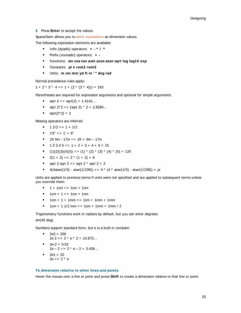
SpaceClaim allows you to enter expressions as dimension values.
The following expression elements are available:
Infix (dyadic) operators: + - * / ^
Prefix (monadic) operators: + -
Functions: sin cos tan asin acos atan sqrt log log10 exp
Constants: pi e root2 root3
Units: m cm mm yd ft in ' " deg rad
Normal precedence rules apply:
1 + 2 * 3 ^ 4 => 1 + (2 * (3 ^ 4))) = 163
Parentheses are required for expression arguments and optional for simple arguments:
sqrt 2 == sqrt(2) = 1.4142…
sqrt 2*2 => (sqrt 2) * 2 = 2.8284…
sqrt(2*2) = 2
Missing operators are inferred:
1 1/2 => 1 + 1/2
1’6” => 1’ + 6”
1ft 6in - 17in => 1ft + 6in – 17in
1 2 3 4 5 => 1 + 2 + 3 + 4 + 5 = 15
(1)(2)(3)(4)(5) => (1) * (2) * (3) * (4) * (5) = 120
2(1 + 2) => 2 * (1 + 2) = 6
sqrt 2 sqrt 2 => sqrt 2 * sqrt 2 = 2
4(4atan(1/5) - atan(1/239)) => 4 * (4 * atan(1/5) - atan(1/239)) = pi
Units are applied to previous terms if units were not specified and are applied to subsequent terms unless you override them:
1 + 1cm => 1cm + 1cm
1cm + 1 => 1cm + 1cm
1cm + 1 + 1mm => 1cm + 1mm + 1mm
1cm + 1 1/2 mm => 1cm + 1mm + 1mm / 2
Trigonometry functions work in radians by default, but you can enter degrees:
sin(45 deg)
Numbers support standard form, but e is a built-in constant:
2e2 = 200 2e 2 => 2 * e * 2 = 10.873…
2e-2 = 0.02 2e – 2 => 2 * e – 2 = 3.436…
2e1 = 20 2e => 2 * e
To dimension relative to other lines and points
Hover the mouse over a line or point and press Shift to create a dimension relative to that line or point.
SpaceClaim User's Guide
26
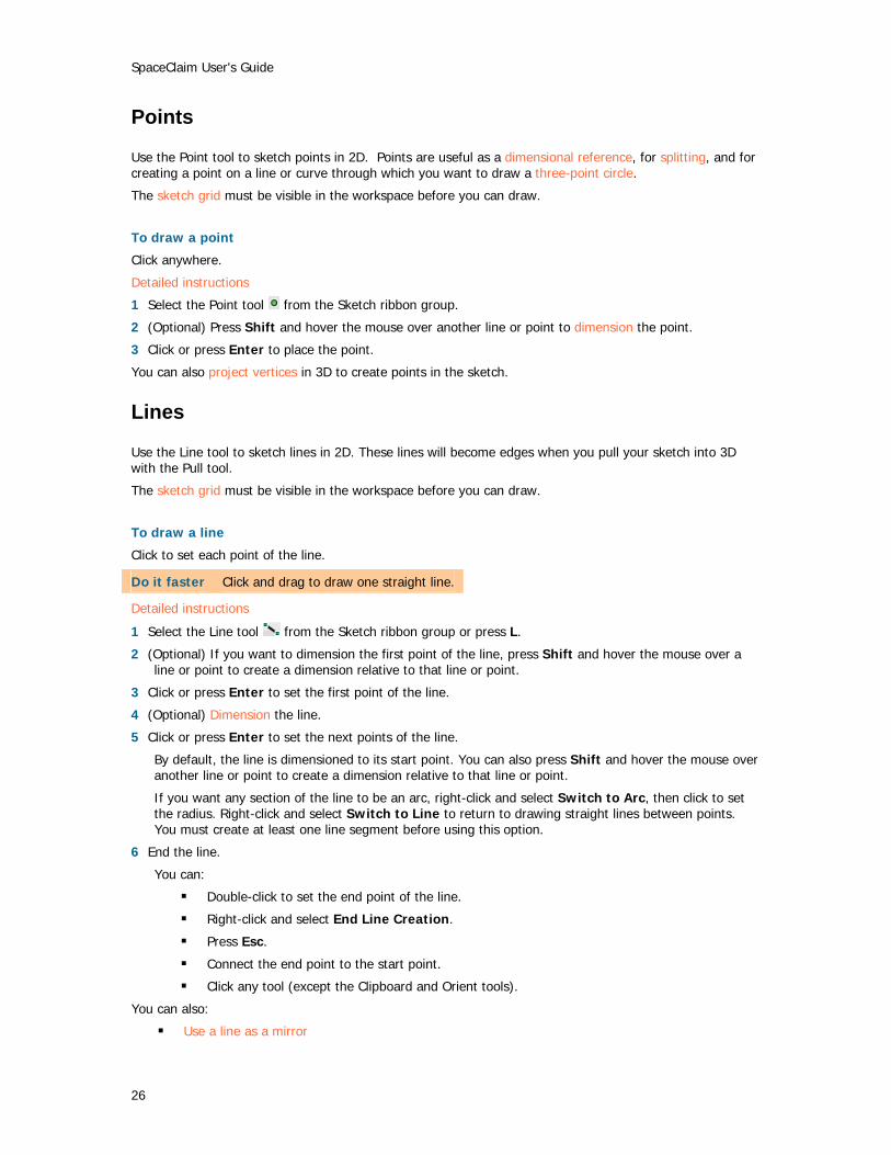
Points
Use the Point tool to sketch points in 2D. Points are useful as a dimensional reference, for splitting, and for creating a point on a line or curve through which you want to draw a three-point circle.
The sketch grid must be visible in the workspace before you can draw.
To draw a point
Click anywhere.
Detailed instructions
1 Select the Point tool from the Sketch ribbon group.
2 (Optional) Press Shift and hover the mouse over another line or point to dimension the point.
3 Click or press Enter to place the point.
You can also project vertices in 3D to create points in the sketch.
Lines
Use the Line tool to sketch lines in 2D. These lines will become edges when you pull your sketch into 3D with the Pull tool.
The sketch grid must be visible in the workspace before you can draw.
To draw a line
Click to set each point of the line.
Do it faster Click and drag to draw one straight line.
Detailed instructions
1 Select the Line tool from the Sketch ribbon group or press L.
2 (Optional) If you want to dimension the first point of the line, press Shift and hover the mouse over a line or point to create a dimension relative to that line or point.
3 Click or press Enter to set the first point of the line.
4 (Optional) Dimension the line.
5 Click or press Enter to set the next points of the line.
By default, the line is dimensioned to its start point. You can also press Shift and hover the mouse over another line or point to create a dimension relative to that line or point.
If you want any section of the line to be an arc, right-click and select Switch to Arc, then click to set the radius. Right-click and select Switch to Line to return to drawing straight lines between points. You must create at least one line segment before using this option.
6 End the line.
You can:
Double-click to set the end point of the line.
Right-click and select End Line Creation.
Press Esc.
Connect the end point to the start point.
Click any tool (except the Clipboard and Orient tools).
You can also:
Use a line as a mirror

Designing
27
Right-click the line and select Set as Mirror Line. Toggle between a line and a construction line
Right-click the line and select Construction On/Off.
Example
Sketching a "racetrack"
Tangent lines
Use the Tangent Line tool to sketch lines tangent to any curves in your design. These lines will become edges when you pull your sketch into 3D with the Pull tool.
The sketch grid must be visible in the workspace before you can draw.
To draw a tangent line
1 Click a curve.
2 Click to set the line's end point.
Detailed instructions
1 Select the Tangent Line tool from the Sketch ribbon panel.
Curves are highlighted as you mouse over them, and the tangency indicator appears at your cursor location. If there are no curves in your design, this tool is disabled; you must add a curve to create a tangent line.
2 Click the curve you want to draw tangent to.
As you move the mouse, the start point moves so that the line remains tangent to the curve.
3 (Optional) Dimension the line with a length.
You cannot dimension from a reference when creating a tangent line.
4 Click or press Enter to set the end point of the line.
If you mouse over another curve, the line snaps so that it is tangent to the second curve. To stop this behavior, Alt+click the end point.
You can also:
Use a tangent line as a mirror
Right-click the line and select Set as Mirror Line. Toggle between a tangent line and a construction line
Right-click the line and select Construction On/Off.
Construction lines
Use the Construction Line tool to draw lines that help you create an accurate sketch. Construction lines become axes in 3D. They are also useful for creating mirrors.
The sketch grid must be visible in the workspace before you can draw.
SpaceClaim User's Guide
28
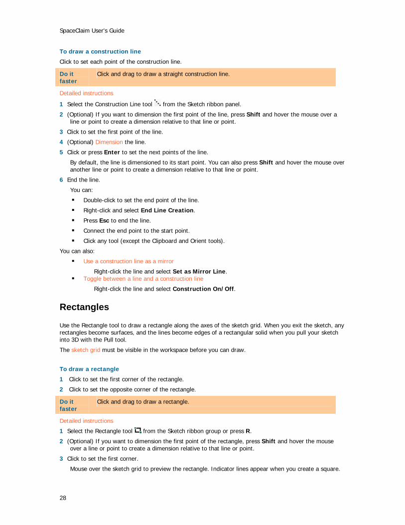
To draw a construction line
Click to set each point of the construction line.
Do it faster
Click and drag to draw a straight construction line.
Detailed instructions
1 Select the Construction Line tool from the Sketch ribbon panel.
2 (Optional) If you want to dimension the first point of the line, press Shift and hover the mouse over a line or point to create a dimension relative to that line or point.
3 Click to set the first point of the line.
4 (Optional) Dimension the line.
5 Click or press Enter to set the next points of the line.
By default, the line is dimensioned to its start point. You can also press Shift and hover the mouse over another line or point to create a dimension relative to that line or point.
6 End the line.
You can:
Double-click to set the end point of the line.
Right-click and select End Line Creation.
Press Esc to end the line.
Connect the end point to the start point.
Click any tool (except the Clipboard and Orient tools).
You can also:
Use a construction line as a mirror
Right-click the line and select Set as Mirror Line. Toggle between a line and a construction line
Right-click the line and select Construction On/Off.
Rectangles
Use the Rectangle tool to draw a rectangle along the axes of the sketch grid. When you exit the sketch, any rectangles become surfaces, and the lines become edges of a rectangular solid when you pull your sketch into 3D with the Pull tool.
The sketch grid must be visible in the workspace before you can draw.
To draw a rectangle
1 Click to set the first corner of the rectangle.
2 Click to set the opposite corner of the rectangle.
Do it faster
Click and drag to draw a rectangle.
Detailed instructions
1 Select the Rectangle tool from the Sketch ribbon group or press R.
2 (Optional) If you want to dimension the first point of the rectangle, press Shift and hover the mouse over a line or point to create a dimension relative to that line or point.
3 Click to set the first corner.
Mouse over the sketch grid to preview the rectangle. Indicator lines appear when you create a square.

Designing
29
4 (Optional) Dimension the rectangle from the first corner or press Shift and hover to create a reference dimension.
5 Click or press Enter to set the opposite corner of the rectangle.
Three-point rectangles
Use the Three-Point Rectangle tool to quickly sketch a rectangle at any angle in 2D. These lines will become the edges of a rectangular solid when you pull your sketch into 3D with the Pull tool.
The sketch grid must be visible in the workspace before you can draw.
To draw a three-point rectangle
1 Click to set the first corner of the rectangle.
2 Click to set the length of the first side.
3 Click to set the length of the second side.
Do it faster
Click and drag to draw the first side, then click to set the length of the second side.
Detailed instructions
1 Select the Three-Point Rectangle tool from the Sketch ribbon panel.
2 (Optional) If you want to dimension the first corner of the rectangle, press Shift and hover the mouse over a line or point to create a dimension relative to that line or point.
3 Click to set the first corner of the rectangle.
Mouse over the sketch grid to preview the rectangle. Indicator lines appear when you create a square or golden rectangle.
4 (Optional) Dimension the first side or press Shift and hover to create a reference dimension.
5 Click or press Enter to set the length of the second side or dimension it.
You can also press Shift and hover to create a reference dimension for the second side.
Circles
Use the Circle tool to sketch a circle in 2D when you know the location of the circle's center and a point on the circle’s edge, or the radius or diameter. The circle can become a cylinder or hole when you pull it into 3D with the Pull tool, or a sphere or torus if you rotate or sweep it.
The sketch grid must be visible in the workspace before you can draw.
To draw a circle
1 Click to set the circle’s center.
2 Click to set the circle's radius.
Detailed instructions
1 Select the Circle tool from the Sketch ribbon panel or press C.
2 (Optional) If you want to dimension the center of the circle, press Shift and hover the mouse over a line or point to create a dimension relative to that line or point.
3 Click to set the circle’s center.
4 (Optional) Dimension the radius.
5 Click or press Enter to set the circle's radius.
The circle will snap to existing sketches or determined circles and arcs in the plane of the sketch.

SpaceClaim User's Guide
30
Do it faster
Click and drag to draw a circle.
Three-point circles
Use the Three-Point Circle tool when you don’t know the center of the circle, but you know where the edge of the circle must be. This tool works with any combination of free points, known points, or tangent attachments. The circle will become a cylinder or hole when you pull it into 3D with the Pull tool. You can also rotate the circle about a line to make a sphere or torus.
The sketch grid must be visible in the workspace before you can draw.
To draw a three-point circle
1 Click to set the first point on the circle's edge.
2 Click to set the second point.
3 Click to set the third point.
Detailed instructions
1 Select the Three-Point Circle tool from the Sketch ribbon panel.
2 (Optional) If you want to dimension the first point of the circle, press Shift and hover the mouse over a line or point to create a dimension relative to that line or point.
3 Click to set the first point on the circle’s edge.
If you click a curve or line, the circle will be drawn tangent to the curve or line, unless you click the midpoint or vertex.
4 (Optional) If you want to dimension the second point of the circle, press Shift and hover the mouse over a line or point to create a dimension relative to that line or point.
5 Click or press Enterto set the second point on the circle’s edge.
As you mouse over the sketch grid, if the circle disappears, the cursor location cannot be included in any circle drawn through the first two points and the current one. If you click a curve or line, the circle will be drawn tangent to the curve or line, unless you click the midpoint or vertex.
6 (Optional) Dimension the radius or press Shift and hover to create a reference dimension.
7 Click or press Enter to set the last point on the circle’s edge.
Construction circles
Use the Construction Circle tool to draw circles that help you create an accurate sketch. Construction circles cannot be pulled into 3D, and are removed when you select a new sketch plane or exit sketching. The construction circle is useful for dimensioning or indicating a circular relationship of objects that lie on a virtual circular line of centers. For example, bolt hole circles around a flange.
The sketch grid must be visible in the workspace before you can draw.
To draw a circle
1 Click to set the circle’s center.
2 Click the set the circle's radius.
Do it faster
Click and drag to draw a construction circle.
Detailed instructions

Designing
31
1 Select the Construction Circle tool from the Sketch ribbon panel.
2 (Optional) If you want to dimension the center of the circle, press Shift and hover the mouse over a line or point to create a dimension relative to that line or point.
3 Click to set the circle’s center.
4 (Optional) Dimension the radius.
5 Click or press Enter to set the circle's radius.
The circle will snap to existing sketches or determined circles and arcs in the plane of the sketch.
Ellipses
Use the Ellipse tool to sketch an ellipse in 2D. The ellipse can become an elliptical solid or hole when you pull your sketch into 3D with the Pull tool. You can also sweep the ellipse in 3D, or rotate it.
The sketch grid must be visible in the workspace before you can draw.
To draw an ellipse
1 Click to set the center of the ellipse.
2 Click to set the overall length and angular orientation of the first axis.
3 Click to set the overall length of the second axis.
Detailed instructions
1 Select the Ellipse tool from the Sketch ribbon panel.
2 (Optional) If you want to dimension the center of the ellipse, press Shift and hover the mouse over a line or point to create a dimension relative to that line or point.
3 Click or press Enterto set the center of the ellipse.
4 Click or press Enter to set the overall length and angular orientation of the first axis.
You can dimension the axis.
5 Click or press Enter to set the length of the second axis.
You can also dimension this axis.
Tangent arcs
Use the Tangent Arc tool to sketch an arc tangent to any single curve or line in your design. This arc will become an edge when you pull your sketch into 3D with the Pull tool.
The sketch grid must be visible in the workspace before you can draw.
To draw a tangent arc
1 Click to set the start point of the arc on a line.
2 Click to set the radius and chord angle of the arc.
Detailed instructions
1 Select the Tangent Arc tool from the Sketch ribbon panel.
Mouse over the sketch grid to highlight curves and lines. If there are no curves or lines in the sketch, the tool is disabled. You must add a curve or line or move the grid to create a tangent arc.
2 Click the line or curve you want to draw tangent to.
Usually, this is done at the endpoint of a line, arc, or spline, but it can be on the line as well. If there are two lines sharing an end point, use the scroll wheel to set tangency to the other line.
You can dimension the radius and chord angle.
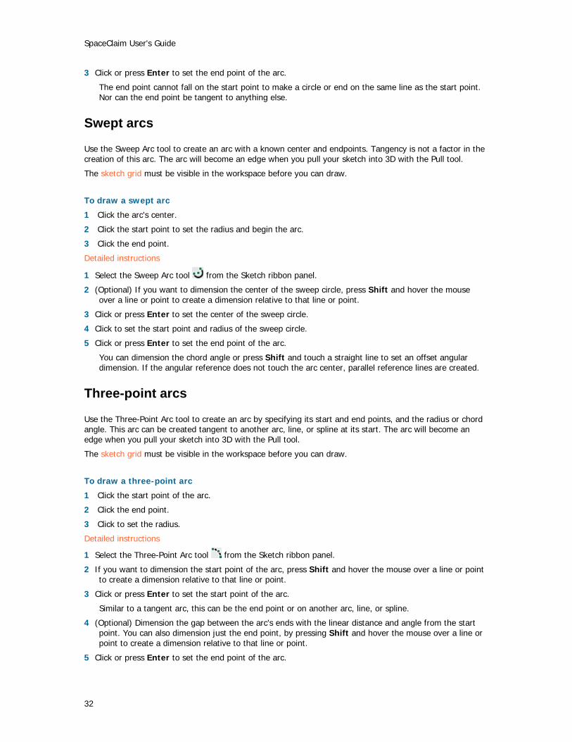
SpaceClaim User's Guide
32
3 Click or press Enter to set the end point of the arc.
The end point cannot fall on the start point to make a circle or end on the same line as the start point. Nor can the end point be tangent to anything else.
Swept arcs
Use the Sweep Arc tool to create an arc with a known center and endpoints. Tangency is not a factor in the creation of this arc. The arc will become an edge when you pull your sketch into 3D with the Pull tool.
The sketch grid must be visible in the workspace before you can draw.
To draw a swept arc
1 Click the arc's center.
2 Click the start point to set the radius and begin the arc.
3 Click the end point.
Detailed instructions
1 Select the Sweep Arc tool from the Sketch ribbon panel.
2 (Optional) If you want to dimension the center of the sweep circle, press Shift and hover the mouse over a line or point to create a dimension relative to that line or point.
3 Click or press Enter to set the center of the sweep circle.
4 Click to set the start point and radius of the sweep circle.
5 Click or press Enter to set the end point of the arc.
You can dimension the chord angle or press Shift and touch a straight line to set an offset angular dimension. If the angular reference does not touch the arc center, parallel reference lines are created.
Three-point arcs
Use the Three-Point Arc tool to create an arc by specifying its start and end points, and the radius or chord angle. This arc can be created tangent to another arc, line, or spline at its start. The arc will become an edge when you pull your sketch into 3D with the Pull tool.
The sketch grid must be visible in the workspace before you can draw.
To draw a three-point arc
1 Click the start point of the arc.
2 Click the end point.
3 Click to set the radius.
Detailed instructions
1 Select the Three-Point Arc tool from the Sketch ribbon panel.
2 If you want to dimension the start point of the arc, press Shift and hover the mouse over a line or point to create a dimension relative to that line or point.
3 Click or press Enter to set the start point of the arc.
Similar to a tangent arc, this can be the end point or on another arc, line, or spline.
4 (Optional) Dimension the gap between the arc's ends with the linear distance and angle from the start point. You can also dimension just the end point, by pressing Shift and hover the mouse over a line or point to create a dimension relative to that line or point.
5 Click or press Enter to set the end point of the arc.

Designing
33
If the start point is on another line, arc, or spline, then the arc will initially be drawn tangent to that line, arc, or spline..
6 Click or press Enter to set the arc's radius.
You can dimension the chord angle or radius.
Splines
Use the Spline tool to sketch splines in 2D. A spline is a continuously curved line, without sharp boundaries (that is, without vertices). Splines can become edges when you pull your sketch into 3D with the Pull tool. Sweeping along a spline in 3D lets you create smooth, curvy shapes.
The sketch grid must be visible in the workspace before you can draw.
To draw a spline
1 Click to set each point of the spline.
2 Double-click to end.
Detailed instructions
1 Select the Spline tool from the Sketch ribbon panel.
2 If you want to dimension the first point of the spline, hover the mouse over a line or point and press Shift to create a dimension relative to that line or point.
3 Click or press Enter to set the first point of the spline.
4 If you want to dimension the next points of the spline, hover the mouse over a line or point and press Shift to create a dimension relative to that line or point. If you click a spline, the dimension is always created from the start point of the spline.
5 Click or press Enter to set the next points of the spline.
You can dimension the spline by entering the coordinate distance from the start point to each point.
6 End the spline.
You can:
Double-click to set the end point of the spline.
Right-click and select Finish Spline.
Press Esc.
Connect the end point to the start point.
Click any tool (except the Clipboard and Orient tools).
You can also:
Move a spline
1 Click the Select tool in the Edit ribbon group.
2 Mouse over the spline to highlight the spline and display its defining points.
3 Click anywhere on the spline except for the defining points, and drag it to move it.
Edit a spline
1 Click the Select tool in the Edit ribbon group.
2 Mouse over the spline to highlight the spline and display its defining points.
2 Click and drag on any internal point or endpoint to move it, leaving the other spline points fixed in space.
3 (Optional) Edit the dimensions associated with that point.
4 Click an endpoint to display its endpoint control handle.

SpaceClaim User's Guide
34
The endpoint control handle is a light blue point at the end of a dotted line extending outwards from the end of the spline. In some cases, these endpoints may be located some distance away from your sketch. Zoom out from the sketch until you can see the endpoint control handle.
If another line, arc, or spline share that endpoint, the endpoint influence may snap into tangency with that sketch entity. To adjust the endpoint influence in this case, move the mouse a short distance away from the endpoint to display the endpoint control handle.
5 Drag the endpoint control handles to change the influence of that endpoint on the shape of the spline.
The amount of the endpoint's influence can be controlled by dragging the endpoint control handle closer to or further away from the endpoint.
Add spline points
1 Click the Select tool in the Edit ribbon group.
2 Mouse over the spline to highlight the spline and display its defining points.
3 Right-click anywhere on the spline except on the defining points, and select Add Spline Point to create another spline point at that location.
Remove spline points
1 Click the Select tool in the Edit ribbon group.
2 Click the spline to highlight it and display its defining points.
3 Right-click the point you want to remove and select Remove Spline Point.
The spline adjusts to accommodate the removal of the point. Create a closed spline
You can create a closed spline in the following ways:
When drawing a spline, end it on the start point.
When editing the spline, drag one endpoint on top of the other point.
Once you have created a closed spline, you cannot edit it into an open spline.
Splitting lines
Use the Split Curve tool to split one line with another line or point.
The sketch grid must be visible in the workspace before you can split lines.
To split a line
1 Select the Split Curve tool from the Sketch ribbon group.
2 Click the line you want to split.
3 Click the line or point that will split the first line where they intersect.
Trimming lines
Use the Trim Away tool to delete any line portion bounded by an intersection with a line or edge.
The sketch grid must be visible in the workspace before you can trim lines.
To delete a bounded line
Click the line portion you want to delete.
Detailed instructions
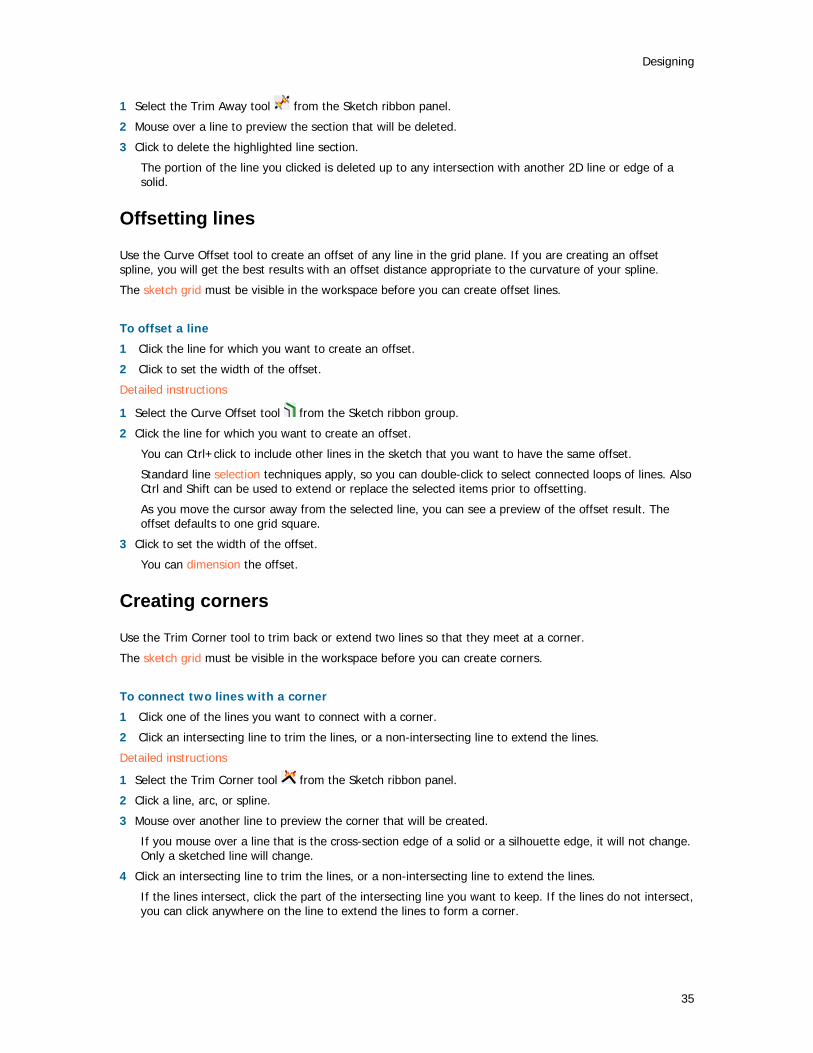
Designing
35
1 Select the Trim Away tool from the Sketch ribbon panel.
2 Mouse over a line to preview the section that will be deleted.
3 Click to delete the highlighted line section.
The portion of the line you clicked is deleted up to any intersection with another 2D line or edge of a solid.
Offsetting lines
Use the Curve Offset tool to create an offset of any line in the grid plane. If you are creating an offset spline, you will get the best results with an offset distance appropriate to the curvature of your spline.
The sketch grid must be visible in the workspace before you can create offset lines.
To offset a line
1 Click the line for which you want to create an offset.
2 Click to set the width of the offset.
Detailed instructions
1 Select the Curve Offset tool from the Sketch ribbon group.
2 Click the line for which you want to create an offset.
You can Ctrl+click to include other lines in the sketch that you want to have the same offset.
Standard line selection techniques apply, so you can double-click to select connected loops of lines. Also Ctrl and Shift can be used to extend or replace the selected items prior to offsetting.
As you move the cursor away from the selected line, you can see a preview of the offset result. The offset defaults to one grid square.
3 Click to set the width of the offset.
You can dimension the offset.
Creating corners
Use the Trim Corner tool to trim back or extend two lines so that they meet at a corner.
The sketch grid must be visible in the workspace before you can create corners.
To connect two lines with a corner
1 Click one of the lines you want to connect with a corner.
2 Click an intersecting line to trim the lines, or a non-intersecting line to extend the lines.
Detailed instructions
1 Select the Trim Corner tool from the Sketch ribbon panel.
2 Click a line, arc, or spline.
3 Mouse over another line to preview the corner that will be created.
If you mouse over a line that is the cross-section edge of a solid or a silhouette edge, it will not change. Only a sketched line will change.
4 Click an intersecting line to trim the lines, or a non-intersecting line to extend the lines.
If the lines intersect, click the part of the intersecting line you want to keep. If the lines do not intersect, you can click anywhere on the line to extend the lines to form a corner.

SpaceClaim User's Guide
36
Creating filleted corners
Use the Trim Fillet tool to trim back or connect two intersecting lines or arcs so that they meet with an arc tangent at both ends.
The sketch grid must be visible in the workspace before you can create filleted corners.
To connect two lines with a fillet
1 Click a line or arc.
2 Click an intersecting line to size and trim the arc.
Detailed instructions
1 Select the Trim Fillet tool from the Sketch ribbon panel.
2 Click a line or arc.
3 Mouse over another line to preview the fillet that will be created.
If you mouse over a line that is the edge of a solid, that edge will not change. Only a sketched line will change. The radius of the arc is previewed as you move the mouse. You can enter a radius to dimension it.
4 Click an intersecting line to trim the lines, or a non-intersecting line to connect the lines.
Where you click on the intersecting line defines the radius of the tangent arc, or you can dimension the fillet by entering its diameter.
If the lines intersect, click the part of the intersecting line you want to keep. (Circles are never trimmed.) If the lines do not intersect, you can click anywhere on the line to extend the lines to form a corner.
Projecting onto the sketch grid
Use the Project to Sketch tool to copy an edge or vertex of a solid to a 2D line or point that you can manipulate with the sketch tools. Except when explicitly selecting a new sketch plane, this is the only sketch tool that can select items that are not on the sketch grid.
The sketch grid must be visible in the workspace before you can project edges onto it.
To project an edge or vertex onto the sketch grid
Click any edge or vertex in your design.
Detailed instructions
1 Select the Project to Sketch tool from the Sketch ribbon panel.
2 Click the edge, edge chain, or vertex you want to project into the sketch plane.
The edge or vertex now appears as a sketched line to show that it is now a line or point in the sketch plane.
Standard edge selection methods apply, so you can double-click, Ctrl+click, and Shift+click to create or modify your selection. Successive double-click cycling replaces the previous selection with the current one in the sketch plane.
Duplicate edges (that appear on top of each other) in the sketch are consolidated when you exit the sketch.
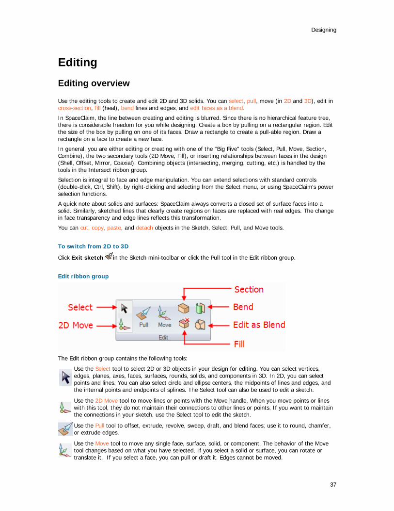
Designing
37
Editing Editing overview
Use the editing tools to create and edit 2D and 3D solids. You can select, pull, move (in 2D and 3D), edit in cross-section, fill (heal), bend lines and edges, and edit faces as a blend.
In SpaceClaim, the line between creating and editing is blurred. Since there is no hierarchical feature tree, there is considerable freedom for you while designing. Create a box by pulling on a rectangular region. Edit the size of the box by pulling on one of its faces. Draw a rectangle to create a pull-able region. Draw a rectangle on a face to create a new face.
In general, you are either editing or creating with one of the "Big Five" tools (Select, Pull, Move, Section, Combine), the two secondary tools (2D Move, Fill), or inserting relationships between faces in the design (Shell, Offset, Mirror, Coaxial). Combining objects (intersecting, merging, cutting, etc.) is handled by the tools in the Intersect ribbon group.
Selection is integral to face and edge manipulation. You can extend selections with standard controls (double-click, Ctrl, Shift), by right-clicking and selecting from the Select menu, or using SpaceClaim's power selection functions.
A quick note about solids and surfaces: SpaceClaim always converts a closed set of surface faces into a solid. Similarly, sketched lines that clearly create regions on faces are replaced with real edges. The change in face transparency and edge lines reflects this transformation.
You can cut, copy, paste, and detach objects in the Sketch, Select, Pull, and Move tools.
To switch from 2D to 3D
Click Exit sketch in the Sketch mini-toolbar or click the Pull tool in the Edit ribbon group.
Edit ribbon group
The Edit ribbon group contains the following tools:
Use the Select tool to select 2D or 3D objects in your design for editing. You can select vertices, edges, planes, axes, faces, surfaces, rounds, solids, and components in 3D. In 2D, you can select points and lines. You can also select circle and ellipse centers, the midpoints of lines and edges, and the internal points and endpoints of splines. The Select tool can also be used to edit a sketch.
Use the 2D Move tool to move lines or points with the Move handle. When you move points or lines with this tool, they do not maintain their connections to other lines or points. If you want to maintain the connections in your sketch, use the Select tool to edit the sketch.
Use the Pull tool to offset, extrude, revolve, sweep, draft, and blend faces; use it to round, chamfer, or extrude edges.
Use the Move tool to move any single face, surface, solid, or component. The behavior of the Move tool changes based on what you have selected. If you select a solid or surface, you can rotate or translate it. If you select a face, you can pull or draft it. Edges cannot be moved.
SpaceClaim User's Guide
38
Use the Section tool to edit solids by moving their edges and vertices in cross-section.
Use the Bend tool to bend straight lines and edges to form an arc. You can also use the Bend tool to adjust the radius of arcs and arced edges. Bend works on straight lines when you are sketching, when you are editing in cross-section, and when you are editing blend sections with the Edit as Blend tool.
Use the Fill tool to fill in the selected region with the surrounding surface or solid. The region must be completely surrounded to be filled.
You can use the Edit as Blend tool to edit any blended face or convert a regular face to a blended one. You can create a new blend section or delete one. You can move any blend section, or you can edit it by moving an edge, moving a vertex, or bending an edge.
Selecting
Use the Select tool to select 2D or 3D objects in your design for editing. You can select vertices, edges, planes, axes, faces, surfaces, rounds, solids, and components in 3D. In 2D, you can select points and lines. You can also select circle and ellipse centers, the midpoints of lines and edges, and the internal points and endpoints of splines.
The Select tool can also be used to edit a sketch.
To select
1 Click to select the highlighted object. Double-click to select an edge loop. (Double-click again to cycle through alternate loops.) Triple-click to select a solid.
2 (Optional) Ctrl+click and Shift+click to add or remove items. Alt+click to create a secondary selection set.
Detailed instructions
1 Select the Select tool from the Edit ribbon panel.
2 Mouse over the vertices, edges, faces in the workspace to preview the selectable items in your design.
If multiple objects occur at your cursor location, use the scroll wheel or arrow keys to preview each one. A vertex is the last item displayed when you scroll.
3 Click to select a vertex, edge, face, or round in 3D; click to select a line or point in 2D.
To select: Do this: All the edges around a face or closed loop
Double-click an edge or line. Double-click again to select the next loop of edges. Repeat as necessary. You can also right-click the edge or line and choose one of the loop options in the Select menu.
All tangent faces Double-click a face. (Tangent faces are created by rounds or when edges are drawn on a face.)
The sides (but not the top and bottom) of a solid
Triple-click the solid and Ctrl+click the top and bottom to remove them from the selection.
A solid or surface body Triple-click the solid, or right-click on the solid and select Select > Body.
A component Right-click on the component and select Select > Component. Everything in the design window or on the sketch grid
Press Ctrl+A. Layout surfaces are not selected.
Layout surfaces or components
Click the object in the Structure panel.
Anything completely within a selection box
Click and drag from the upper left to lower right to draw a selection box. You can also right-click and select Select > Box Select, then click and drag.

Designing
39
The inverse of the current selection
Right-click a selected object and select Select > Inverse Selection.
A protrusion Right-click on a protrusion and select Select > Protrusion. A depression Right-click inside a depression and select Select > Depression. One member of a pattern Right-click a pattern member and select Select > Pattern >
Member. All members of a pattern Right-click a pattern member and select Select > Pattern > All
Members. Anything partially in a selection box
Click and drag from the lower right to upper left to draw a selection box.
If any object was part of a group selection used to perform an action, the other parts of the group are highlighted when that object is selected. Click again to select the entire highlighted group.
4 (Optional) Ctrl+click and Shift+click to add or remove items from the selection set.
Ctrl+click to add or remove one item from the selection set. Shift+click to add everything between your first click and the Shift+click to the selection. You can add or remove items both in the workspace and on the Structure panel.
5 (Optional) Alt+click to create a secondary selection set.
Hold down the Alt key while performing any of the other selection techniques (double-click, triple-click, Ctrl, Shift) to create the second selection set. Alternate selections are shown in blue, and are used to guide the actions of the Pull and Move tools.
Click an unoccupied space in the Design window to clear the selection.
Tool guides
Within the Select tool, there are two tool guides that offer you alternative behaviors:
The Select tool guide is active by default. This tool offers the standard click, double-click, triple-click, Ctrl+click, Shift+click, and Alt+click behavior.
Use the Select Bounds to Extend Selection tool guide to click a face or edge to extend the current selection to include all objects bound by that face or edge. If you select a boundary, then click a contiguous face, all faces will be selected up to the boundary.
Options
You can add to a selection using the power selection tool on the Selection panel.
Selectable objects that are coincident in 2D and 3D
Sometimes objects appear at the same location in 2D. For example, a vertex and end point of a line are often located at the same point in space. When selecting, be sure to check that you have selected the correct object by using the scroll wheel without moving the mouse.

SpaceClaim User's Guide
40
Editing with the Pull tool
Use the Pull tool to offset, extrude, revolve, sweep, draft, and blend faces; use it to round, chamfer, or extrude edges. You can select a face, then pull, dragging anywhere to act, or you can click, drag, and release a highlighted face. In general, the result of a pull stays selected or highlighted after the pull operation.
The action of the Pull tool depends on which faces and edges you select to work with, and which faces, planes, or edges you select to drive the change. For example, if you choose to work with a face, then select an edge to "drive" the pull, the Pull tool infers that you want to pivot the face around that edge. When multiple actions can be inferred, you can use the tool guides to correct the Pull tool's inference. The Pull tool maintains any offset, mirror, pattern, or coaxial relationships.
When you are pulling a face, there are two main decisions you need to make. The first is to determine the direction you want to pull in. A default direction is offered to you, but it can be overridden using the Direction tool guide. The second is to determine what is going to happen at the edges of the face. By default, the edges of the face are determined by its neighbors, but you can override this behavior by including the edges in your Pull selection to create an extrusion.
To create and edit solids
1 Select the face and/or edges you want to work with.
2 (Optional) Alt+click the face or edge that will drive the pull.
3 Drag in the direction of the Pull arrow.
Detailed instructions
1 Select the Pull tool from the Edit ribbon panel.
Mouse over faces and edges in your design to preview the natural Pull direction. If your mouse is over multiple faces or edges, use the scroll wheel to preview the Pull direction for each one.
2 Select the faces and/or edges you want to pull to create 3D solids or surfaces.
3 (Optional) Alt+click to select the face or edge that will drive the change.
You can also select the appropriate tool guide, then click the face or edge. The driving edge or face is shown in blue.
4 (Optional) Select options from the Options panel, or right-click and select them from the mini-toolbar.
5 Click and drag in the direction of the Pull arrow to create or edit a solid.
To dimension the pull, type the distance you want to pull and press Enter. (If the dimension field does not appear editable, start typing while you are pulling to enter the dimension.)
You do not have to click and drag on (or even near) the Pull arrow. In fact, we recommend that you move your cursor away from the arrow for more precise control of the pull. The only important input to the Pull tool is the direction in which you are moving the cursor. When you pull, contiguous solids are automatically combined.
If you want to pull in a head-on view, use the ruler at the bottom right corner of the Design window to pull instead of the Pull arrow. Slide the gray bar to the left to subtract material, and to the right to add material.
You can also click the Up To tool guide, then click the face that sets the plane up to which you want to pull.
Press Esc to cancel the Pull.
Using the Pull tool, you can:
Offset or extrude faces
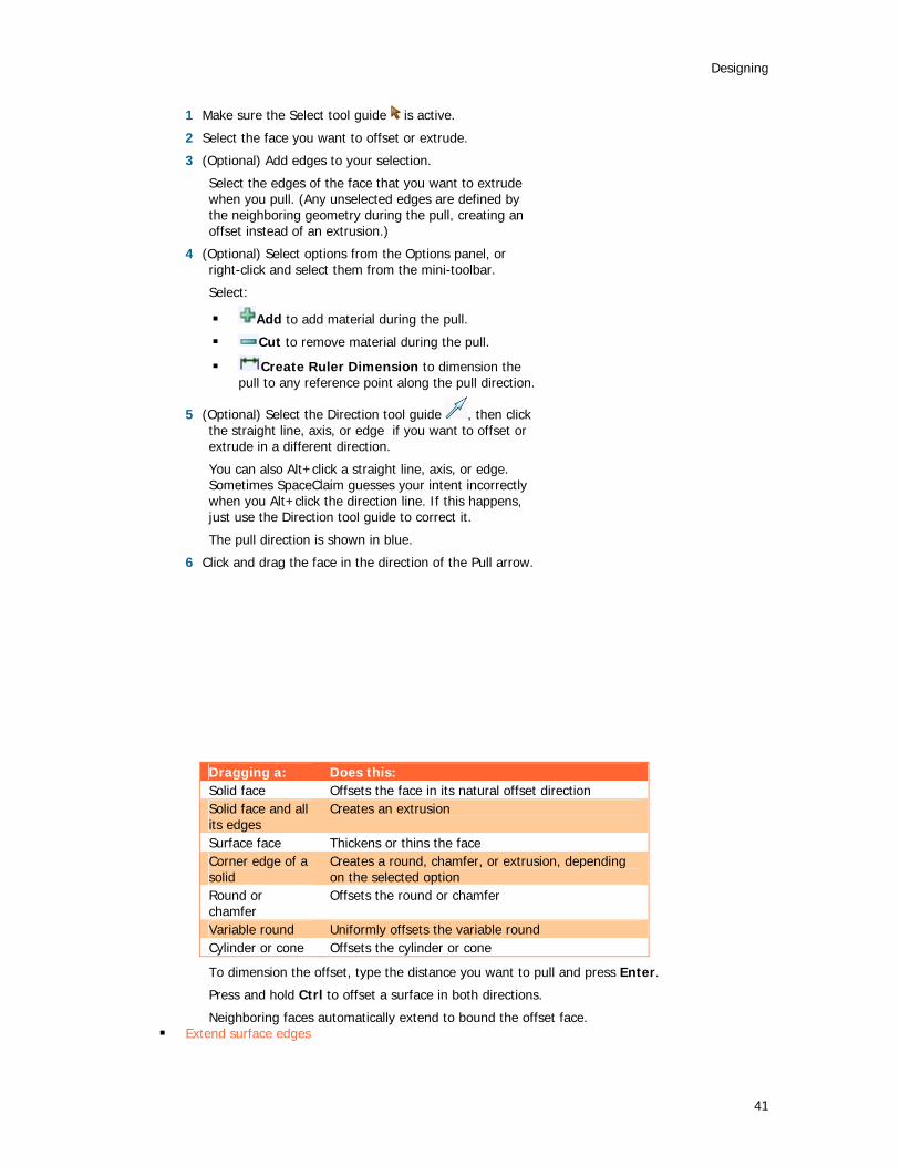
Designing
41
1 Make sure the Select tool guide is active.
2 Select the face you want to offset or extrude.
3 (Optional) Add edges to your selection.
Select the edges of the face that you want to extrude when you pull. (Any unselected edges are defined by the neighboring geometry during the pull, creating an offset instead of an extrusion.)
4 (Optional) Select options from the Options panel, or right-click and select them from the mini-toolbar.
Select:
Add to add material during the pull.
Cut to remove material during the pull.
Create Ruler Dimension to dimension the pull to any reference point along the pull direction.
5 (Optional) Select the Direction tool guide , then click the straight line, axis, or edge if you want to offset or extrude in a different direction.
You can also Alt+click a straight line, axis, or edge. Sometimes SpaceClaim guesses your intent incorrectly when you Alt+click the direction line. If this happens, just use the Direction tool guide to correct it.
The pull direction is shown in blue.
6 Click and drag the face in the direction of the Pull arrow.
Dragging a: Does this: Solid face Offsets the face in its natural offset direction Solid face and all its edges
Creates an extrusion
Surface face Thickens or thins the face Corner edge of a solid
Creates a round, chamfer, or extrusion, depending on the selected option
Round or chamfer
Offsets the round or chamfer
Variable round Uniformly offsets the variable round Cylinder or cone Offsets the cylinder or cone
To dimension the offset, type the distance you want to pull and press Enter.
Press and hold Ctrl to offset a surface in both directions.
Neighboring faces automatically extend to bound the offset face. Extend surface edges
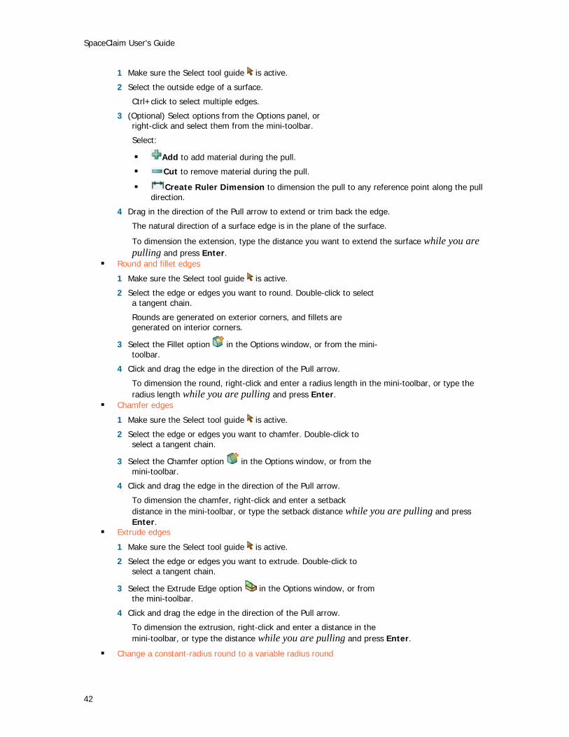
SpaceClaim User's Guide
42
1 Make sure the Select tool guide is active.
2 Select the outside edge of a surface.
Ctrl+click to select multiple edges.
3 (Optional) Select options from the Options panel, or right-click and select them from the mini-toolbar.
Select:
Add to add material during the pull.
Cut to remove material during the pull.
Create Ruler Dimension to dimension the pull to any reference point along the pull direction.
4 Drag in the direction of the Pull arrow to extend or trim back the edge.
The natural direction of a surface edge is in the plane of the surface.
To dimension the extension, type the distance you want to extend the surface while you are pulling and press Enter.
Round and fillet edges
1 Make sure the Select tool guide is active.
2 Select the edge or edges you want to round. Double-click to select a tangent chain.
Rounds are generated on exterior corners, and fillets are generated on interior corners.
3 Select the Fillet option in the Options window, or from the mini-toolbar.
4 Click and drag the edge in the direction of the Pull arrow.
To dimension the round, right-click and enter a radius length in the mini-toolbar, or type the radius length while you are pulling and press Enter.
Chamfer edges
1 Make sure the Select tool guide is active.
2 Select the edge or edges you want to chamfer. Double-click to select a tangent chain.
3 Select the Chamfer option in the Options window, or from the mini-toolbar.
4 Click and drag the edge in the direction of the Pull arrow.
To dimension the chamfer, right-click and enter a setback distance in the mini-toolbar, or type the setback distance while you are pulling and press Enter.
Extrude edges
1 Make sure the Select tool guide is active.
2 Select the edge or edges you want to extrude. Double-click to select a tangent chain.
3 Select the Extrude Edge option in the Options window, or from the mini-toolbar.
4 Click and drag the edge in the direction of the Pull arrow.
To dimension the extrusion, right-click and enter a distance in the mini-toolbar, or type the distance while you are pulling and press Enter.
Change a constant-radius round to a variable radius round

Designing
43
1 Make sure the Select tool guide is active.
2 Select the internal, smooth edge or corner edge of an existing round.
3 Click and drag the edge in the direction of the Pull arrow to set the round radius at that point.
Two rounds that intersect at a shared edge can be made variable together by selecting the shared sharp edge for modification. Both rounds become variable at that point. They can be made variable independently by selecting the sharp end edge that is not shared by the rounds.
Revolve faces
1 Make sure the Select tool guide is active.
2 Select the surfaces, faces, or solids you want to revolve.
3 Alt+click the straight line, axis, or edge to set the revolve axis.
You can also select the Rotate tool guide , then click to set the revolve axis. The revolve axis is shown in blue.
4 (Optional) Select options from the Options panel, or right-click and select them from the mini-toolbar.
Select:
Add to add material during the pull.
Cut to remove material during the pull.
Full Pull to revolve 360 degrees.
5 Click and drag in the direction of the Pull arrow to revolve the selected object, or select Full Pull from the Options panel or mini-toolbar.
Neighboring faces automatically extend to define the boundaries of the revolved faces of solids. Revolving from a flat surface face has no neighboring faces, so it makes new face boundaries.
To dimension the rotation, type the rotation angle while you are pulling and press Enter.
Revolve edges
1 Make sure the Select tool guide is active.
2 Select the edges you want to revolve.
3 Alt+click the straight line, axis, or edge to set the revolve axis.
You can also select the Rotate tool guide , then click the revolve axis. The revolve axis is shown in blue.
4 Click and drag in the direction of the Pull arrow to revolve the selected edge.
Ctrl+click to select edges of faces along with the face to force the pull tool to create new neighboring faces to contain these edges (essentially changing from a draft to a revolve). Unlike other CAD products, SpaceClaim allows revolving planar and non-planar edges and faces about lines that do not lie in those planes. This allows skewed rotational solids and surfaces.
To dimension the rotation, type the rotation angle while you are pulling and press Enter.
Sweep faces
1 Make sure the Select tool guide is active.
2 Select the surface or face you want to sweep.

SpaceClaim User's Guide
44
3 Alt+click the line or edge along which you want to sweep.
You can also select the Sweep tool guide , then click the sweep trajectory. The sweep trajectory is shown in blue. Alt+double-click to select a tangent chain.
Sweep works best when the sweep line is perpendicular to and touches the face you want to sweep. To quickly draw a sweep line, select the face, click the Line or Spline tool, select the Move Grid tool from the mini-toolbar, press Shift, and drag the Move handle's axis to rotate the sketch grid 90 degrees.
To quickly sketch a face perpendicular to a desired trajectory, select the end of the trajectory and select a sketching tool to place the sketch grid at that point. Then draw the face.
4 (Optional) Select options from the Options panel, or right-click and select them from the mini-toolbar.
Select:
Normal to Trajectory to keep the swept surface normal to the sweep trajectory.
Add to add material during the pull.
Cut to remove material during the pull.
5 Click and drag in the direction of the Pull arrow to sweep the selected objects, or select Full Pull from the Options panel or mini-toolbar to sweep the entire length of the trajectory.
Draft faces about a pivot plane
1 Make sure the Select tool guide is active.
2 Select the face or faces you want to draft.
3 Alt+click the face or surface about which you want to draft.
You can also select the Draft tool guide , then click the face or surface. The draft face or surface is shown in blue.
4 (Optional) Select options from the Options panel, or right-click and select them from the mini-toolbar.
Select:
Add to add material during the pull.
Cut to remove material during the pull.
Draft Both Sides topivot the face on the opposite side of the reference face as well as the selected face.
5 Click and drag in the direction of the Pull arrow to draft the selected faces.
To dimension the draft, type the rotation angle while you are pulling and press Enter. Blend faces
1 Make sure the Select tool guide is active.
2 Select the surfaces or faces you want to blend through.
The edges of the blend are displayed. If they aren't, check that Blend option is selected in the Options window.
3 (Optional) Click and drag the blend points to modify the blend edges.
4 (Optional) Select options from the Options panel, or right-click and select them from the mini-toolbar.
Select:
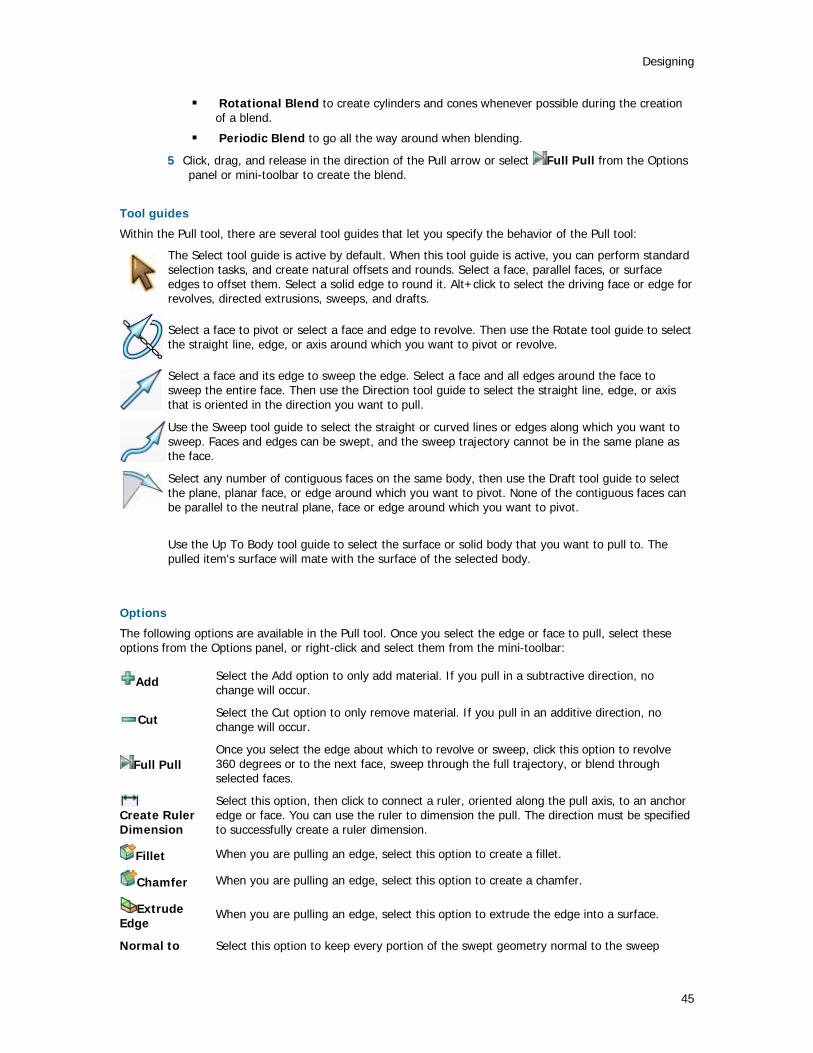
Designing
45
Rotational Blend to create cylinders and cones whenever possible during the creation of a blend.
Periodic Blend to go all the way around when blending.
5 Click, drag, and release in the direction of the Pull arrow or select Full Pull from the Options panel or mini-toolbar to create the blend.
Tool guides
Within the Pull tool, there are several tool guides that let you specify the behavior of the Pull tool:
The Select tool guide is active by default. When this tool guide is active, you can perform standard selection tasks, and create natural offsets and rounds. Select a face, parallel faces, or surface edges to offset them. Select a solid edge to round it. Alt+click to select the driving face or edge for revolves, directed extrusions, sweeps, and drafts.
Select a face to pivot or select a face and edge to revolve. Then use the Rotate tool guide to select the straight line, edge, or axis around which you want to pivot or revolve.
Select a face and its edge to sweep the edge. Select a face and all edges around the face to sweep the entire face. Then use the Direction tool guide to select the straight line, edge, or axis that is oriented in the direction you want to pull.
Use the Sweep tool guide to select the straight or curved lines or edges along which you want to sweep. Faces and edges can be swept, and the sweep trajectory cannot be in the same plane as the face.
Select any number of contiguous faces on the same body, then use the Draft tool guide to select the plane, planar face, or edge around which you want to pivot. None of the contiguous faces can be parallel to the neutral plane, face or edge around which you want to pivot.
Use the Up To Body tool guide to select the surface or solid body that you want to pull to. The pulled item's surface will mate with the surface of the selected body.
Options
The following options are available in the Pull tool. Once you select the edge or face to pull, select these options from the Options panel, or right-click and select them from the mini-toolbar:
Add Select the Add option to only add material. If you pull in a subtractive direction, no change will occur.
Cut Select the Cut option to only remove material. If you pull in an additive direction, no change will occur.
Full Pull Once you select the edge about which to revolve or sweep, click this option to revolve 360 degrees or to the next face, sweep through the full trajectory, or blend through selected faces.
Create Ruler Dimension
Select this option, then click to connect a ruler, oriented along the pull axis, to an anchor edge or face. You can use the ruler to dimension the pull. The direction must be specified to successfully create a ruler dimension.
Fillet When you are pulling an edge, select this option to create a fillet.
Chamfer When you are pulling an edge, select this option to create a chamfer.
Extrude Edge
When you are pulling an edge, select this option to extrude the edge into a surface.
Normal to Select this option to keep every portion of the swept geometry normal to the sweep

SpaceClaim User's Guide
46
Trajectory trajectory.
Blend Faces Select this option to force the Pull tool to blend between the selected faces.
Rotational Blend
Select this option to create cylinders and cones whenever possible during the creation of a blend.
Periodic Blend Select this option to go all the way around when blending.
Maintain Offset Select this option to maintain the offset relationship when pulling.
Show All Offset Baselines Select this option to display all baseline faces in blue.
Draft Both Sides
Select this option to pivot the face on the opposite side of the reference face as well as the selected face.
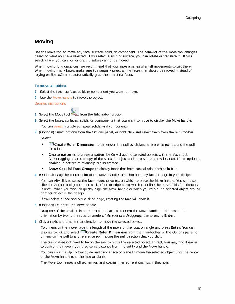
Designing
47
Moving
Use the Move tool to move any face, surface, solid, or component. The behavior of the Move tool changes based on what you have selected. If you select a solid or surface, you can rotate or translate it. If you select a face, you can pull or draft it. Edges cannot be moved.
When moving long distances, we recommend that you make a series of small movements to get there. When moving many faces, make sure to manually select all the faces that should be moved, instead of relying on SpaceClaim to automatically grab the interstitial faces.
To move an object
1 Select the face, surface, solid, or component you want to move.
2 Use the Move handle to move the object.
Detailed instructions
1 Select the Move tool from the Edit ribbon group.
2 Select the faces, surfaces, solids, or components that you want to move to display the Move handle.
You can select multiple surfaces, solids, and components.
3 (Optional) Select options from the Options panel, or right-click and select them from the mini-toolbar.
Select:
Create Ruler Dimension to dimension the pull by clicking a reference point along the pull direction.
Create patterns to create a pattern by Ctrl+dragging selected objects with the Move tool. Ctrl+dragging creates a copy of the selected object and moves it to a new location. If this option is enabled, a pattern relationship is also created.
Show Coaxial Face Groups to display faces that have coaxial relationships in blue.
4 (Optional) Drag the center point of the Move handle to anchor it to any face or edge in your design.
You can Alt+click to select the face, edge, or vertex on which to place the Move handle. You can also click the Anchor tool guide, then click a face or edge along which to define the move. This functionality is useful when you want to quickly align the Move handle or when you rotate the selected object around another object in the design.
If you select a face and Alt+click an edge, rotating the face will pivot it.
5 (Optional) Re-orient the Move handle.
Drag one of the small balls on the rotational axis to reorient the Move handle, or dimension the orientation by typing the rotation angle while you are dragging, thenpressing Enter.
6 Click an axis and drag in that direction to move the selected object.
To dimension the move, type the length of the move or the rotation angle and press Enter. You can also right-click and select Create Ruler Dimension from the mini-toolbar or the Options panel to dimension the pull to any reference point along the pull direction that you click.
The cursor does not need to be on the axis to move the selected object. In fact, you may find it easier to control the move if you drag some distance from the entity and the Move handle.
You can click the Up To tool guide and click a face or plane to move the selected object until the center of the Move handle is at the face or plane.
The Move tool respects offset, mirror, and coaxial inferred relationships, if they exist.
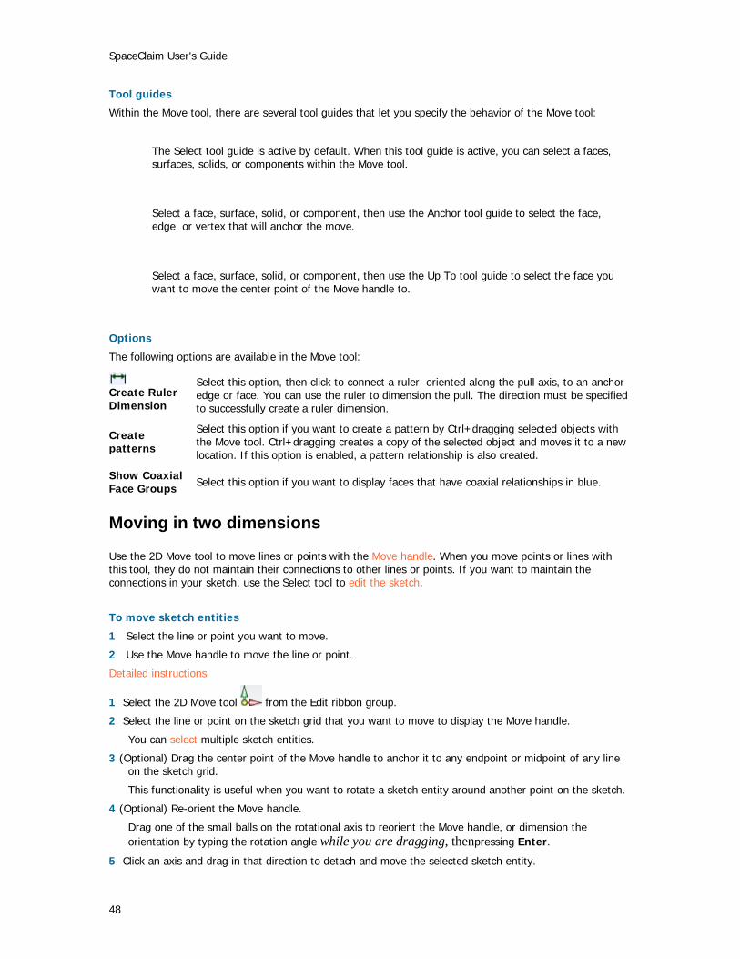
SpaceClaim User's Guide
48
Tool guides
Within the Move tool, there are several tool guides that let you specify the behavior of the Move tool:
The Select tool guide is active by default. When this tool guide is active, you can select a faces, surfaces, solids, or components within the Move tool.
Select a face, surface, solid, or component, then use the Anchor tool guide to select the face, edge, or vertex that will anchor the move.
Select a face, surface, solid, or component, then use the Up To tool guide to select the face you want to move the center point of the Move handle to.
Options
The following options are available in the Move tool:
Create Ruler Dimension
Select this option, then click to connect a ruler, oriented along the pull axis, to an anchor edge or face. You can use the ruler to dimension the pull. The direction must be specified to successfully create a ruler dimension.
Create patterns
Select this option if you want to create a pattern by Ctrl+dragging selected objects with the Move tool. Ctrl+dragging creates a copy of the selected object and moves it to a new location. If this option is enabled, a pattern relationship is also created.
Show Coaxial Face Groups Select this option if you want to display faces that have coaxial relationships in blue.
Moving in two dimensions
Use the 2D Move tool to move lines or points with the Move handle. When you move points or lines with this tool, they do not maintain their connections to other lines or points. If you want to maintain the connections in your sketch, use the Select tool to edit the sketch.
To move sketch entities
1 Select the line or point you want to move.
2 Use the Move handle to move the line or point.
Detailed instructions
1 Select the 2D Move tool from the Edit ribbon group.
2 Select the line or point on the sketch grid that you want to move to display the Move handle.
You can select multiple sketch entities.
3 (Optional) Drag the center point of the Move handle to anchor it to any endpoint or midpoint of any line on the sketch grid.
This functionality is useful when you want to rotate a sketch entity around another point on the sketch.
4 (Optional) Re-orient the Move handle.
Drag one of the small balls on the rotational axis to reorient the Move handle, or dimension the orientation by typing the rotation angle while you are dragging, thenpressing Enter.
5 Click an axis and drag in that direction to detach and move the selected sketch entity.

Designing
49
To dimension the move, type the length of the move or the rotation angle and press Enter.
The cursor does not need to be on the axis to move the selected object. In fact, you may find it easier to control the move if you drag some distance from the entity and the Move handle.
Editing in cross-section
Use the Section tool to edit solids by moving their edges and vertices in cross-section.
To edit solids in cross-section
1 Select or de-select options based on whether you want to maintain and view relationships while you edit in cross-section.
2 Select the face you want to use to create the cross-section.
3 (Optional) Move or rotate the cross-section grid and click the Section tool when you are finished.
4 Click and drag the edges and vertices of the cross-section to edit them.
You can also bend edges with the Bend tool.
We recommend zooming into your design so that it is easy to select the correct entity. For example, if you are trying to select an edge, but your design appears very small in the Design window, it is possible to accidentally select a midpoint or endpoint of the edge instead. Moving the midpoint or endpoint of an edge will not be reflected by a mirrored entity.
Options
The following options are available in the Section tool:
Maintain Mirror Select this option to maintain the influence of mirrors in your design while editing.
Maintain Offset Select this option to maintain the influence of baselines in your design while editing. Baseline faces are shown as blue edges when viewed in cross-section.
Show Offset Baselines Select this option to display the baselines of offset relationships in blue.
Show Coaxial Face Groups Select this option if you want to display faces that have coaxial relationships in blue.
Filling
Use the Fill tool to fill in the selected region with the surrounding surface or solid. Fill can "heal" many cuts made into geometry, such as chamfers and rounds, subtractive revolves, and regions removed by removing regions in the Combine tool.
The Fill tool is useful for cleaning up surface edges and capping surfaces.
To fill a region
1 Select the edges that define a surface region, or the faces that define a region within a solid.
2 Click the Fill tool .
You can use the Fill tool to: Cap a surface
Select the edges of the surface you want to cap and click the Fill tool. Patch a surface

SpaceClaim User's Guide
50
Select the edges of a void in the middle of a surface or the edges of a void on the edge of a surface and click the Fill tool.
Fill in a round or chamfer
Select the round or chamfer and click the Fill tool. Remove a protrusion or depression
Select the protrusion or depression and click the Fill tool.
Bending
Use the Bend tool to bend straight lines and edges to form an arc. You can also use the Bend tool to adjust the radius of arcs and arced edges. Bend works on straight lines when you are sketching and when you are editing in cross-section.
To bend a line or edge
1 Select the Bend tool from the Edit ribbon group.
2 If you are working in 3D, select the face containing the edge.
3 Click and drag a line or arc to bend it or change its radius.
Editing faces as a blend
You can use the Edit as Blend tool to edit any blended face or convert a regular face to a blended one. You can create a new blend section or delete one. You can move any blend section, or you can edit it by moving an edge, moving a vertex, or bending an edge.
If a face was originally created as a blend, the original blend surfaces will appear for editing, even if the faces originated as imported geometry. Any two planar faces can be edited as a blend, but a single face cannot be edited as a blend.
To edit a face as a blend
1 Select the faces you want to convert to blended surfaces, or select existing blended faces.
2 Use the Edit as Blend tool to display the blend sections.
3 Move, rotate, or edit the interior blend sections.
You can also add or delete interior blend sections.
Detailed instructions
1 Select the faces you want to convert to blended surfaces, or select existing blended surfaces.
We recommend that you use the more powerful Select tool to do this, but you can also select faces within the Edit as Blend tool after the next step.
2 Click the Edit as blend tool in the Edit ribbon group to display the blend sections.
If you did not pre-select the faces, you can select them in the Edit as Blend tool using the Select tool
guide .
Click a blend section to select it.
3 Move, rotate, or edit the interior blend sections.
To move or rotate the blend section
Click the Move tool guide and drag the Move handle to move or rotate the blend section.

Designing
51
To move a vertex or edge
Click the Edit tool guide , click a vertex or edge of the blend section, and drag it to edit the blend section.
To bend an edge
Click the Edit tool guide , right-click the edge, and select Bend. Drag in or out to bend the edge.
4 Add or remove interior blend sections.
To add a blend section
Click the Add Blend Section tool guide and click the face to insert a new blend section through the face at that location. The orientation of the new section is determined by the orientation of its neighboring blend sections.
To remove a blend section
Click a blend section, then click the Delete Blend Section tool guide to delete it. The faces are redrawn between the remaining blend sections. If you delete the wrong blend section, you can always press Ctrl+Z to undo.
Tool guides
Within the Edit as blend tool, there are several tool guides that help step you through the editing process:
If you did not pre-select the faces to edit, you can select them from within the Edit as Blend tool using the Select tool guide.
Select the Move Blend Plane tool guide to move and orient the selected blend plane using the Move handle.
Make edits to any blend section with the Edit Blend Section tool guide. You can move, bend, and replace edges or move vertices. Just click to select the vertex or edge you want to edit.
Select the Add New Blend Section tool guide to add new blend sections by clicking on the face to insert a new blend section through the face. You can modify your new blend sections just like the others.
Select the Delete Blend Section tool guide to click any blend section to delete it.
Power selection
SpaceClaim offers a powerful method for selecting similar objects to the one currently selected in the Selection window.

SpaceClaim User's Guide
52
To select objects similar to the currently selected object
1 Select any 3D object.
2 Click the Selection tab to display the Selection panel.
The Selection tab is initially located at the bottom of the Structure panel. It displays the number and type of objects currently selected.
3 (Optional) Select a type from the drop-down list to show only those objects with the selected relationship.
Select All Types to display all the geometry related to your selection.
4 Click the Find icon to search for related objects in your design.
Related objects are displayed in the Related list. Mouse over the objects in the list to highlight those objects in the Design window.
5 Click any number of the related objects in the list to add them to the current selection.

Designing
53
Intersecting You can use the intersect tools to merge and split a solid or surface in your design with another solid or surface. You can merge and split solids or surfaces with other solids or surfaces, split a body with a face, and split a face with another face. You can also project the edges of a face onto other solids and surfaces in your design.
SpaceClaim's intersection capabilities include the full suite of geometry combination, all done with one major tool (Combine) and two minor ones (Split Body and Split Face). Combine always takes two or more objects. The split tools always act on one object and that object is automatically selected from the cutter or projection face.
To understand what the Combine tool can do, the first step is to know which objects can be handled. Solid objects have faces that meet at corner edges. Edges that lie on faces can be deleted, but corners cannot. Surface objects have faces that come together at internal edges, and are surrounded by outside edges. Outside edges can be extended. Internal edges can be deleted if they are bounded by planar faces. For the purposes of combine, planes can be thought of as surface faces that extend across the design.
When surfaces enclose a volume, they automatically change into solid objects. When edges of the same surface become coincident, they will automatically merge. Planes cannot be split by any combine operation, but they can be used to split with. In general, layer, color, and visibility in the structure tree propagates from the first selected item (the target) to the result. What happens as a result of the combination can be overridden with the options (both in the panel and the mini-toolbar).
There is complete control over the pieces that solids and surfaces get cut into. When appropriate, the user will be prompted to remove regions, and this is entirely optional.
Intersect ribbon group
The Intersect ribbon group contains the following tools:
Use the Combine tool to merge and split solids and surfaces.
Use the Split Body tool to split a solid by one or more of its faces or edges. Then select one or more regions for deletion.
Use the Split Face tool to create an edge on a face by splitting it with another face or surface.
Use the Project to Solid tool to create edges on a solid's face by extending the edges of another solid or surface.
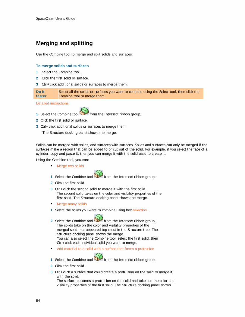
SpaceClaim User's Guide
54
Merging and splitting
Use the Combine tool to merge and split solids and surfaces.
To merge solids and surfaces
1 Select the Combine tool.
2 Click the first solid or surface.
3 Ctrl+click additional solids or surfaces to merge them.
Do it faster
Select all the solids or surfaces you want to combine using the Select tool, then click the Combine tool to merge them.
Detailed instructions
1 Select the Combine tool from the Intersect ribbon group.
2 Click the first solid or surface.
3 Ctrl+click additional solids or surfaces to merge them.
The Structure docking panel shows the merge.
Solids can be merged with solids, and surfaces with surfaces. Solids and surfaces can only be merged if the surfaces make a region that can be added to or cut out of the solid. For example, if you select the face of a cylinder, copy and paste it, then you can merge it with the solid used to create it.
Using the Combine tool, you can:
Merge two solids
1 Select the Combine tool from the Intersect ribbon group.
2 Click the first solid.
3 Ctrl+click the second solid to merge it with the first solid. The second solid takes on the color and visibility properties of the first solid. The Structure docking panel shows the merge.
Merge many solids
1 Select the solids you want to combine using box selection.
2 Select the Combine tool from the Intersect ribbon group. The solids take on the color and visibility properties of the merged solid that appeared top-most in the Structure tree. The Structure docking panel shows the merge. You can also select the Combine tool, select the first solid, then Ctrl+click each individual solid you want to merge.
Add material to a solid with a surface that forms a protrusion
1 Select the Combine tool from the Intersect ribbon group.
2 Click the first solid.
3 Ctrl+click a surface that could create a protrusion on the solid to merge it with the solid. The surface becomes a protrusion on the solid and takes on the color and visibility properties of the first solid. The Structure docking panel shows

Designing
55
the merge.
Merge two surfaces that share edges
1 Select the Combine tool from the Intersect ribbon group.
2 Click the first surface.
3 Ctrl+click the second surface to merge it with the first surface. The second surface takes on the color and visibility properties of the first surface. The Structure docking panel shows the merge.
Merge two surfaces that intersect to form an enclosed region
1 Select the surfaces that intersect to form an enclosed region using box selection.
2 Select the Combine tool from the Intersect ribbon group. The enclosed region becomes a solid and takes on the color and visibility properties of the merged surface that appeared top-most in the Structure tree. The Structure docking panel shows the merge.
To split solids and surfaces
1 Select the target.
2 Select the cutter.
3 (Optional) Select the region of the target to delete.
Do it faster
If you want to split a body by a face of the body, select the Split Body tool. If you want to create an edge on a face, select the Split Face tool.
Detailed instructions
1 Click the Combine tool from the Intersect ribbon panel.
2 Select the solid or surface you want to cut.
The Select Cutter tool guide is activated.
3 (Optional) Control the behavior of the cut by selecting options.
4 Click the surface you want to use to cut the solid.
Depending on the option you chose, the cutting surface will be kept or deleted. Review the information in the Structure panel to see the solids or surfaces created by the cut.
Mouse over the target solid to see the regions created by the cut.
5 Click each region you want to delete.
When you are finished selecting the areas to be deleted, click the Select Target tool guide to combine some more, or select another tool.
Using the Combine tool, you can:
Split a solid with a surface or plane
1 Select the Combine tool from the Intersect ribbon group.
2 Click the solid you want to cut.
3 Click the surface you want to cut the solid with.
4 Mouse over the solid to see the regions created by the cut.
5 Click the region you want to delete.
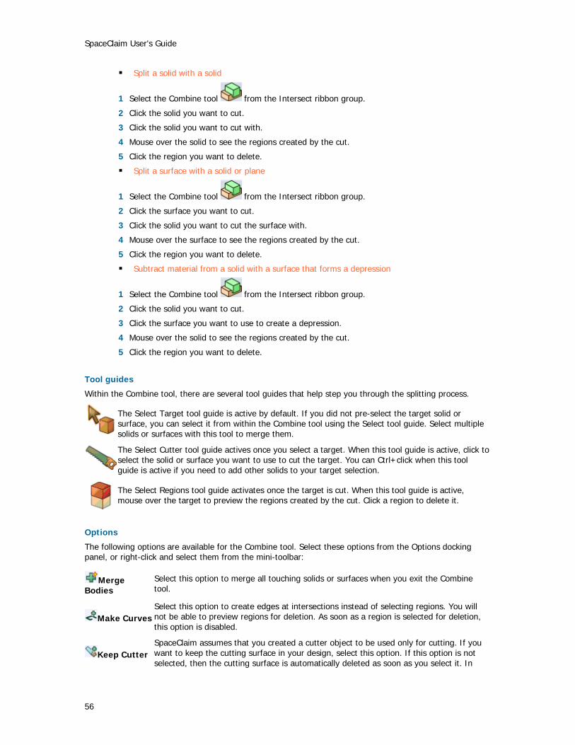
SpaceClaim User's Guide
56
Split a solid with a solid
1 Select the Combine tool from the Intersect ribbon group.
2 Click the solid you want to cut.
3 Click the solid you want to cut with.
4 Mouse over the solid to see the regions created by the cut.
5 Click the region you want to delete.
Split a surface with a solid or plane
1 Select the Combine tool from the Intersect ribbon group.
2 Click the surface you want to cut.
3 Click the solid you want to cut the surface with.
4 Mouse over the surface to see the regions created by the cut.
5 Click the region you want to delete.
Subtract material from a solid with a surface that forms a depression
1 Select the Combine tool from the Intersect ribbon group.
2 Click the solid you want to cut.
3 Click the surface you want to use to create a depression.
4 Mouse over the solid to see the regions created by the cut.
5 Click the region you want to delete.
Tool guides
Within the Combine tool, there are several tool guides that help step you through the splitting process.
The Select Target tool guide is active by default. If you did not pre-select the target solid or surface, you can select it from within the Combine tool using the Select tool guide. Select multiple solids or surfaces with this tool to merge them.
The Select Cutter tool guide actives once you select a target. When this tool guide is active, click to select the solid or surface you want to use to cut the target. You can Ctrl+click when this tool guide is active if you need to add other solids to your target selection.
The Select Regions tool guide activates once the target is cut. When this tool guide is active, mouse over the target to preview the regions created by the cut. Click a region to delete it.
Options
The following options are available for the Combine tool. Select these options from the Options docking panel, or right-click and select them from the mini-toolbar:
Merge Bodies
Select this option to merge all touching solids or surfaces when you exit the Combine tool.
Make Curves Select this option to create edges at intersections instead of selecting regions. You will not be able to preview regions for deletion. As soon as a region is selected for deletion, this option is disabled.
Keep Cutter SpaceClaim assumes that you created a cutter object to be used only for cutting. If you want to keep the cutting surface in your design, select this option. If this option is not selected, then the cutting surface is automatically deleted as soon as you select it. In

Designing
57
other words, cutter objects are normally "used up" unless you select this option. A kept cutter can be a surface or solid, but either way only the regions of the target can be removed. Kept cutters are not violated.
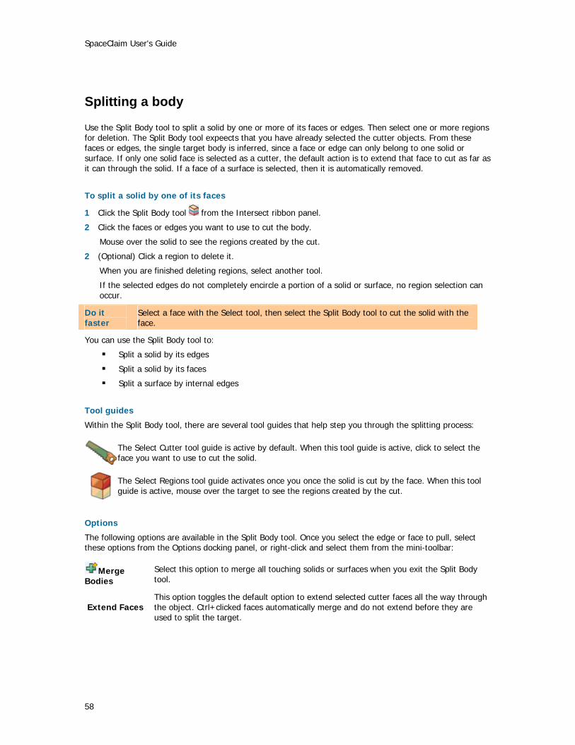
SpaceClaim User's Guide
58
Splitting a body
Use the Split Body tool to split a solid by one or more of its faces or edges. Then select one or more regions for deletion. The Split Body tool expeects that you have already selected the cutter objects. From these faces or edges, the single target body is inferred, since a face or edge can only belong to one solid or surface. If only one solid face is selected as a cutter, the default action is to extend that face to cut as far as it can through the solid. If a face of a surface is selected, then it is automatically removed.
To split a solid by one of its faces
1 Click the Split Body tool from the Intersect ribbon panel.
2 Click the faces or edges you want to use to cut the body.
Mouse over the solid to see the regions created by the cut.
2 (Optional) Click a region to delete it.
When you are finished deleting regions, select another tool.
If the selected edges do not completely encircle a portion of a solid or surface, no region selection can occur.
Do it faster
Select a face with the Select tool, then select the Split Body tool to cut the solid with the face.
You can use the Split Body tool to:
Split a solid by its edges
Split a solid by its faces
Split a surface by internal edges
Tool guides
Within the Split Body tool, there are several tool guides that help step you through the splitting process:
The Select Cutter tool guide is active by default. When this tool guide is active, click to select the face you want to use to cut the solid.
The Select Regions tool guide activates once you once the solid is cut by the face. When this tool guide is active, mouse over the target to see the regions created by the cut.
Options
The following options are available in the Split Body tool. Once you select the edge or face to pull, select these options from the Options docking panel, or right-click and select them from the mini-toolbar:
Merge Bodies
Select this option to merge all touching solids or surfaces when you exit the Split Body tool.
Extend Faces This option toggles the default option to extend selected cutter faces all the way through the object. Ctrl+clicked faces automatically merge and do not extend before they are used to split the target.

Designing
59
Splitting a face
Use the Split Face tool to create an edge on a face by splitting it with another face or surface.
To create an edge on a face
1 Click the Split Face tool from the Intersect ribbon panel.
2 Click to select the face you want to split.
Mouse over faces in your design to preview the edge that will be created on the target.
3 Click another face or surface to split the selected face with an edge.
Tool guides
Within the Split Body tool, there are two tool guides that help step you through the splitting process:
The Select Target tool guide is active by default. If you did not pre-select the target face or surface, you can select it from within the Split Face tool using the Select tool guide. Ctrl+click multiple surfaces or solid faces or select them before entering the Split Face tool.
The Select Cutter tool guide actives once you select a target. When this tool guide is active, click to select the face or surface you want to use to create an edge on the target.
Projecting to a solid
Use the Project to Solid tool to create edges on a solid's face by extending the edges of another solid or surface.
To project the edges of a face or surface to a solid
1 Select the Project to Solid tool from the Intersect ribbon panel.
2 Click the face or surfaces whose edges you want to project perpendicular to the face.
The nearest solid faces are determined automatically.
3 (Optional) Alt+click a face or edge to set another direction for the projection.
To project edges to selected faces of a solid
1 Select the Project to Solid tool from the Intersect ribbon panel.
2 Click the face or surfaces whose edges you want to project perpendicular to the face.
The nearest solid faces are determined automatically.
3 Select the Use Selected Faces option in the Options panel.
The purple edges disappear.
4 Select the faces you want to project onto individually.
Options
The following options are available for the Project to Solid tool. Select these options from the Options docking panel, or right-click and select them from the mini-toolbar:
Use Selected Faces Select this option to project only onto the faces you choose.
Project Through Select this option to project edges on all faces through the entire solid instead of just

SpaceClaim User's Guide
60
Solids the faces closest to the "projector" face.
Extend Projected Edges
When a projected edge does not completely span across a face, this option extends the lines until another edge is reached.

Designing
61
Inserting The Insert tools allow you to create relationships between the solids and surfaces in your design. You can create axis, shell, offset, or mirror relationships, as well as linear and circular patterns. Tools to insert a planar surface and move the sketch grid are also provided to help create relationships.
Inserting a plane
You can define a plane by selecting various faces, edges, axes, or lines in your design. The plane will extend a small amount beyond the edges of the face to make it easier to work with. The plane will maintain this margin around all the objects in your design, extending and trimming itself as you add, remove, or move solids within your design.
Planes are useful for creating layouts and annotations. Planes are not linked to the geometry used to create them; they must be explicitly selected to move along with other items. You can also use a plane to quickly clip your design to show only the geometry behind the plane.
To insert a plane
1 Select one of the following: Select a: To insert a plane: Planar face That contains the face Two parallel planar faces At the midpoint between the two faces Axial face Tangent to the face at the selection point Two axial faces with parallel axes
Tangent to both faces as close as possible to the selection points
Planar face and edge Through the edge and normal to the face Planar edges That contains the edges Axis That contains the axis Two parallel axes That contains the axes Endpoint of any line Through the endpoint and normal to the line at the endpoint Three points That contains those three points Two planar lines That contains those two lines
2 Select the Plane tool from the Insert ribbon group to insert the plane.
To clip your design with a plane
Right-click a plane and select Clip with Datum Plane to display only the portions of your design that appears behind the plane.
Inserting an axis
You can extend any axis in your design to make it available for revolves or rotations. The axis will extend small amount beyond the edge of the space containing your design. It will maintain this margin extending and trimming it as you add, remove, or move objects in your design. Axes are not linked to the geometry used to create them (unless they are an extension of existing axes); they must be explicitly selected to move along with other items.
To insert an axis
1 Select one of the following: Select a: To insert an axis:

SpaceClaim User's Guide
62
Axial face That contains the face's axis Two, non-parallel planar faces
At the intersection of the theoretical planes containing the two faces
Linear edge That contains the edge Cylinder and tangent plane
At the intersection of the cylinder and plane
Line That contains the line Circle or arc That contains the center point and is normal to the line Two points Through both points
2 Select the Axis tool from the Insert ribbon group to insert the axis.
Moving the sketch grid
Use the Move Grid tool to move the sketch grid. If you are sketching, you can select this tool by clicking it on the Sketch mini-toolbar. Make successive sketches by moving the grid after sketching closed line regions. These closed lines turn into regions when you move the grid.
To move the sketch grid
1 Click the Move Grid tool in the Insert ribbon group.
2 (Optional) Select any sketch entities that you want to move along with the sketch grid.
3 Drag along the arms of the Move handle to move or rotate the sketch grid.
Press Shift while dragging to snap the move to angular and linear increments based on your snap settings.
The Manipulator can be moved around by dragging the center ball onto appropriate entities on the sketch grid.
Creating a linear or rectangular pattern
You can create a linear or rectangular pattern of protrusions or depressions. In SpaceClaim, any pattern member can be used to modify the pattern after you create it.
To create a linear pattern
1 Select a protrusion or depression to be the first member of the pattern.
2 Select the Move tool.
3 Check the Create patterns box in the Options panel.
4 Ctrl+drag the first member to copy it in a linear direction.
5 Mouse up to set the location of the last member of the linear pattern. All pattern members will be created between the first member and this member in a straight line.
6 Press Tab, enter the number of members you want to have in the whole pattern in the Count field, and press Enter to create the linear pattern.
To create a rectangular pattern
Follow the steps for the linear pattern, but select a linear pattern as the first member of the pattern.
To edit a pattern
1 Select the face of one pattern member to display the pattern count and dimensions.

Designing
63
2 Press Tab to edit the pattern's properties, then press Enter.
To add rounds or chamfers to a pattern
1 Select the edge or edges of a pattern member.
2 Right-click the selected edge and click Select > Pattern > Edges to select all the corresponding edges in the pattern.
3 Modify the edge(s) to create a round or chamfer.
Creating a circular or cylindrical pattern
You can create a linear or rectangular pattern of protrusions or depressions. In SpaceClaim, any pattern member can be used to modify the pattern after you create it.
To create a circular pattern
1 Select a protrusion or depression to be the first member of the pattern.
2 Select the Move tool.
3 Check the Create patterns box in the Options panel.
4 Alt+click to center the Move tool on the center of the circular pattern.
5 Ctrl+drag the first member to copy it in a rotational direction.
As soon as you pass a certain rotation threshold, you can preview the possible patterns. If you want a more closely-packed pattern, edit the pattern after you create it.
6 Mouse up to select the circular pattern.
7 Press Tab to enter the number of members you want to have in the whole pattern in the Count field.
To edit a pattern
1 Select the face of one pattern member to display the pattern count and dimensions.
2 Press Tab to edit the pattern's properties, then press Enter.
To add rounds or chamfers to a pattern
1 Select the edge or edges of a pattern member.
2 Right-click the selected edge and click Select > Pattern > Edges to select all the corresponding edges in the pattern.
3 Modify the edge(s) to create a round or chamfer.
Turning a solid into a shell
Use the Shell tool to remove one of the faces of the solid and create a shell of a specified thickness. You can then use the Shell tool to remove other sides of the shell. SpaceClaim automatically creates an offset relationship between the sides of the solid for you.
To create a shell
1 Select the Shell tool from the Insert ribbon panel.
Mouse over the solids in your design to highlight the faces that could be removed.
2 Click the face you want to remove.

SpaceClaim User's Guide
64
The face is removed and a shell is created with the default thickness of 1/4" or 1/8". You can set this default thickness. The baseline of the offset is shown in blue.
3 (Optional) Right-click to change the thickness of the shell.
Any other shells created with the Shell tool will use this thickness. There are two undo commands on the mini-toolbar that appears.
Tool guides
This tool guide is active by default. Select a side of the solid to remove it and create a shell.

Designing
65
Creating an offset relationship
Use the Offset tool to create an offset relationship between two faces. This relationship will be maintained in the other 2D and 3D editing tools.
To create an offset relationship
1 Click the Offset tool in the Insert ribbon panel.
Mouse over your design to see the faces eligible for offset relationships.
2 (Optional) Control the behavior of the cut by selecting options.
Select the All the Same option if you want to select all contiguous face pairs that have the same offset distance as the pair you selected. If this option is not selected, the offset relationship is only created for the selected pair of faces.
2 Click the first face.
3 Click the second face.
You have now established an offset relationship between the face pair and other contiguous face pairs with the same offset distance (if the All the Same option is selected). The Toggle Baseline tool guide activates.
4 (Optional) Click to select the baseline face(s).
Tool guides
Within the Offset tool, there are several tool guides that help step you through the editing process:
The Face Pair tool guide is active by default. Select the two faces to look for all the solids in your design that have the same offset distance.
When the Toggle Baseline tool guide is active, click the faces that you want to be the baseline of the offset.
Creating a mirror relationship
Use the Mirror tool to designate a face or plane as a mirror. The plane becomes a persistent mirror once you create geometry using the mirror.
To mirror solids and faces
1 Select the plane you want to be a mirror, or select two faces of a solid between which you want to create a mirror plane.
2 Select the solid or face you want to mirror.
Detailed instructions
1 (Optional) Create the plane you want to use as a mirror using the Insert Plane tool and position it with the Move tool.
2 Click the Mirror tool in the Insert ribbon panel.
You can use the Mirror tool to:
Mirror a body or face

SpaceClaim User's Guide
66
1 Click the Mirror Body or Mirror Face tool guide .
Mouse over the solids or faces in your design to preview the solid or face that will be created on the other side of the mirror plane.
2 Click the solid or face to create the mirrored solid or face.
The mirror plane is also drawn and will persist in other tools.
Set up a mirror relationship between two faces
1 Click the Setup Mirror tool guide.
As you mouse over the faces in your design, the eligible faces are highlighted. A face is eligible if it is parallel to another face in your design.
2 Click two parallel faces.
The second face is highlighted in blue and the mirror plane appears halfway between the two faces. Actions on one face will now be mirrored on the other face.
Remove a mirror face or plane
1 Click the Remove Mirror tool guide.
Mouse over the solids or faces in your design to preview the solid or face that will be created on the other side of the mirror plane.
2 Click the solid or face to create the mirrored solid or face.
You can temporarily disable a plane in any tool. Select a mirrored face to display the mirror plane, then click the mirror icon to disable the mirror. Click the mirror icon again to enable the mirror.
Tool guides
Within the Mirror tool, there are several tool guides that help step you through the mirroring process:
The Select Mirror tool guide is active by default. Select a face or plane to use it as a mirror.
The Mirror Body tool guide activates automatically once you select a mirror face or plane. Mouse over the solids in your design to preview the solid that will be created by the mirror. Select the solid to mirror it.
Once you select a mirror face or plane, use the Mirror Face tool guide to select the faces you want to mirror. Mousing over the faces before you click them previews the face that will be created by the mirror.
The Setup Mirror tool can be used any time to create a mirror plane between two faces. Only those two faces will be affected by the mirror.
Use the Remove Mirror tool to select the mirror plane or face you want to remove.

Designing
67
Assembling components An assembly is a set of parts. When working with assemblies, the first selection in the first assembly command is the face to which all other parts will orient. When you align, center, or orient one component to another, relationship elements are created in the component you selected at the beginning of all your assembly operations. If your components are not fitting together the way you expect, try disabling some of these alignment relationships in the Structure window.
Use the Align, Center, and Orient tools to create mating conditions on the components in your design. You can toggle the conditions on and off, flip their alignment to the other side of the plane, and delete them in the Structure tree.
To toggle a mating condition
Uncheck the mating condition checkbox in the Structure tree to disable the mating condition. Check the box to enable the mating condition.
To delete a mating condition
Right-click the mating condition in the Structure tree and select Delete Mating Condition.
Inserting components into your design
You can import any number of components or assemblies into your design. Each assembly is imported into the center of the workspace, and the components of the assembly are displayed in the Structure window. SpaceClaim allows you to insert almost any CAD file, including ProE (.prt and .asm), Solidworks (.sldprt and .sldasm), Inventor (.ipt), CATIA version 4 and 5 (.CATPart and .CATProduct), Unigraphics (.prt), STEP (.stp and .step), VDA (.vda), IGES (.igs and .iges), AutoCAD (.dwg, .dxf), Parasolid (.x_t and .x_b), and ACIS (.sat and .sab) files.
To insert a component or assembly
1 Select the Insert from File tool from the Assembly ribbon group.
2 Navigate to the component and double-click to insert it.
The component is placed in the center of the workspace and its components (if it is an assembly) appear in the Structure panel. Assemblies imported from other modeling software can have only one color applied.
Aligning components
Use the Align tool to align the planar faces of different components.
To align the planar faces of two components
1 Right-click the component you want to stay in its current location and select Active Part.
2 Select the two faces that you want to align.
3 Click the Align tool in the Assembly ribbon group.
The two faces are aligned along the same plane, and an Align Plane mating condition appears under the non-active component. If you want to align the non-active component to the other side of the plane, right-click the Align Planes mating condition in the Structure tree and select Reverse Sense.

SpaceClaim User's Guide
68
The first mating condition you create determines which of the two parts are dependent and which is independent. The mating condition is placed under the active component if was already designated as the dependent part.
Centering components
Use the Center tool to align the axes of two components.
To align the axes of two components
1 Right-click the component you want to stay in its current location and select Active Part.
2 Select the axes that you want to align.
You can also select the faces defined by the axes.
3 Click the Center tool in the Assembly ribbon panel.
The two axes of the components are aligned and a Center Axes mating condition is created in the Structure tree under the non-active part.
The first mating condition you create determines which of the two parts are dependent and which is independent. The mating condition is placed under the active component if was already designated as the dependent part.
Orienting components
Use the Orient tool to align the directions of different components.
To orient two components
1 Center the two components.
2 Right-click the component you want to stay in its current location and select Active Part.
3 Select the two faces that you want to orient.
4 Click the Orient tool in the Assembly ribbon group.
The two faces are oriented, and an Orient Directions mating condition appears under the non-active component.
The first mating condition you create determines which of the two parts are dependent and which is independent. The mating condition is placed under the active component if was already designated as the dependent part.
Measuring Select a tool from the Measure ribbon group to display measurements for the edges, faces, and solids in your design.
Measure ribbon group
The Measure ribbon group contains the following tools:

Designing
69
Use the Mass Properties tool to display volume information for the solids in your design.
Use the Measure tool to display measurements of the edges and faces in your design.


71
Detailing The tools you use to detail your designs to communicate with others or to submit your designs for review are found on SpaceClaim's Detailing tab. With the detailing tools, you can annotate, create drawing sheets, and review changes to designs.
You can customize detailing settings to conform to standards.
Design tools are grouped into the following Ribbon panels:
Orient Quickly display a particular view of your design.
Annotation Create notes on your design with text, dimensions, geometric tolerances, and datum symbol objects.
Views Add views to a drawing sheet.
Sheet Setup Format a drawing sheet
Markup Create markup slids to illustrate the changes made to a design.

SpaceClaim User's Guide
72
Annotations You can annotate your designs, drawings, and 3D markups with notes, dimensions, and geometric tolerances.
Creating notes
Use the Create Note tool to annotate your designs, drawing sheets, and 3D markups. You can use this tool to create and edit notes.
To create a note
1 Select the Create Note tool from the Annotation ribbon group in the Detailing tab.
Mouse over the faces of your design to preview the eligible annotation planes.
2 Click a face to create the plane on which to place the note.
To create a plane for a cylinder, select the cylinder's axis.
3 Click to place the note on the plane.
To move the note box, mouse over the edge of the box until the cursor changes to the 2D Move icon. To size the box containing the note, drag the handles of the note box (the white circles). To rotate the note, drag the rotation handle.
4 Enter the text of the note.
You can adjust the font, size, style (bold, italic, underline), and alignment of the text within the box using the other tools in the Annotation ribbon panel, or by right-clicking the annotation and selecting from the mini-toolbar.
To edit an existing note, click it to move, rotate, or reformat it.
Creating note leaders
Use the Note Leader tool to create a arrow from your note.
To create a note leader
1 Select the Note Leader tool from the Annotation ribbon panel in the Detailing tab.
Mouse over notes on the active annotation plane to see the possible ways to connect the note leader to the note.
2 Click a note's connection point to draw the first segment of the note leader.
Mouse over your design to highlight the geometry to which you can attach the end of the note leader.
3 Click to set each point of the note leader line.
4 End the note leader.
Click a vertex, edge, or face to attach the end of the note leader to it, or double-click to end the note leader at any point. The end of the note leader is an arrow unless you attach it to a face.
Creating dimension annotations
Use the Dimension tool to add a measurement to your design, drawing sheet, or 3D markup.

Detailing
73
To create a dimension note
1 Select the Dimension tool from the Annotation ribbon panel in the Detailing tab.
Mouse over the faces of your design to preview the eligible annotation planes.
2 Click an edge or face to create a dimension annotation.
3 Drag to place the dimension.
4 (Optional) Click the arrowhead to cycle through alternative leaders.
5 (Optional) Click the dimension text to edit it.
You can edit the text and adjust the font, size, style (bold, italic, underline), and alignment of the text within the box using the other tools in the Annotation ribbon panel, or by right-clicking the annotation and selecting from the mini-toolbar.
You can also move the note box, mouse over the edge of the box until the cursor changes to the 2D Move icon. To size the box containing the note, drag the handles of the note box (the white circles). To rotate the note, drag the rotation handle.
Creating geometric tolerance annotations
Use the Datum Symbol and Geometric Tolerance tools in the Annotation ribbon group in the Detailing tab to add a tolerance to your design, or 3D markup. In SpaceClaim, geometric tolerances are not created automatically. You can enter anything in a geometric tolerance, so we recommend that you read the geometric tolerance tooltips carefully to create intelligent geometric tolerance annotations.
To create a geometric tolerance annotation
1 Select the Datum Symbol tool .
Mouse over the faces of your design to preview the eligible annotation planes.
2 Click to place the datum symbol on the appropriate annotation plane.
3 Draw the note leader.
4 Click the Geometric Tolerance tool .
5 Click to place the geometric tolerance annotation on the appropriate annotation plane and display the Format tab containing the tools you need to create the annotation.
6 Select the symbol from the Symbol drop-down list.
7 Enter a tolerance and enter a symbol from the Symbols ribbon group in the Tolerance field.
8 Press Esc to exit the annotation.
To edit a geometric tolerance annotation
1 Press Esc to cancel any actions and selections.
2 Click the geometric tolerance annotation once to open it for editing.
Displaying measurements
Use the Measure tool to display measurements of the edges and faces in your design.
To view a measurement
1 Select the Measure tool from the Measure ribbon group.
Mouse over your design to preview the faces and edges eligible for measurement.

SpaceClaim User's Guide
74
2 Click an edge or face to display measurement information.
Select two edges or faces to display the distance and angle between them.
Displaying mass properties
Use the Mass Properties tool to display volume information for the solids in your design.
To view mass properties of a solid
1 Select the Mass Properties tool from the Measure ribbon group.
2 Click a solid in the Structure tree or by triple-clicking it in the Design window to display its volume, center of mass, and principle moments and axes.
Detailing
75
Drawing sheets SpaceClaim helps you create drawing sheets. When you create a new drawing sheet, views of your design are created for you automatically. You can then add, remove, and edit these views, as well as move them around on the sheet using the tools in the Detailing tab. Drawing sheets are saved within your design.
When you are working within the Detailing tab, you may find it efficient to press S (or Esc if you are using another tool) to access the Select tool.
To create a new drawing sheet
Select New > New Drawing Sheet from the application menu.
A drawing sheet containing top, front, and right-side views appears in the Design window, and the Drawing Sheet appears in the Structure tree.
To display a drawing sheet in the Design window
Right-click the sheet in the Structure tree and select Open Sheet.
To delete a drawing sheet
Right-click the sheet in the Structure tree and select Delete.
Working with views
You can add and remove views from the drawing sheet, move them around the sheet, and modify their properties.
To add a view to the drawing sheet
Select one of the following tools from the Views ribbon group on the Detailing tab:
General View tool to add a new, independent view. Click the drawing sheet to add the view at that location.
Projected View tool to create a view projected from one of the other views on the drawing sheet. Select the view you want to use to create the projection and drag from the center of the view over the edge of the face you want to project to preview the projected view. Click to place the projected view onto the drawing sheet.
Cross Section tool to convert one of the drawings on the sheet to a cross-section through one of the other views on the sheet. Select the view you want to use to convert to a cross-section. Mouse over another drawing to display the cross-section indicator lines. Drag the indicator until the cross section you want to use is displayed. Hover over edges to snap to their midpoints. Click to select the cross-section.
To select a view on the drawing sheet
1 Press S to activate the Select tool. If you are in another tool, you can press Esc to cancel that action and activate the Select tool.
2 Mouse just outside the view on the drawing sheet until a dashed box around the view is displayed.
3 Click the box to select the view.
SpaceClaim User's Guide
76
To move a view on the drawing sheet
1 Select the view.
2 Drag the view to move it. Projected and cross-section views move together as a group.
To modify a view
1 Select the view.
2 Modify the view's properties in the Options panel or right-click and modify the view using the mini-toolbar.
Formatting a drawing sheet
You can select a template to apply to the drawing sheet, orient the page, select a paper size for the sheet. When you select the format and size of the drawing sheet, SpaceClaim automatically adjusts the scale. You can customize this scale for the sheet.
You format a drawing sheet using the tools in the Sheet Setup group on the Detailing tab.
To apply a template to the drawing sheet
1 Select the Format tool .
2 Select the template you want to apply.
If you want to create a custom format, save the .scdoc file into the /Library/DrawingFormats directory. To save a custom format as a default format, backup the existing .scdoc files and give your .scdoc file the same name as the default file.
To orient the page
1 Select the Orientation tool .
2 Select a portrait or landscape orientation for the page.
To select a page size
1 Select the Size tool .
2 Select the paper size.
To adjust the scale of all views on the drawing sheet
Enter a new scale in the Scale tool's drop-down field.
Detailing
77
3D markup SpaceClaim allows you to create 3D markup slides so that you can clearly communicate the changes to solid models and assemblies. Slides can be exported in PowerPoint and XPS formats.
To create a 3D markup
1 Open the design you want to mark up in the Design window.
2 Select Save As New Version from the Application menu to create a new version of your design.
3 Select New 3D Markup from the Application menu to create a new 3D markup slide.
The slide is shown in the 3D Markup panel, the design window, and the Structure tree. The new version of the design is labelled the Reference Design.
4 Select the Insert tool from the Design tab and insert a previous version of the design into the slide.
The design appears in the Structure tree, labelled as the Alternate Version. In the Design window, the previous version of the design is displayed in the wireframe transparent style and is placed directly on top of the new version.
5 Make your changes to the Reference Design.
You can use all the SpaceClaim design tools to make your changes to the 3D markup. Your changes are reflected in all slides.
6 Customize the slide using the tools in the Markup group in the Detailing tab.
You can document the dimension changes in dimension annotations, color the faces based on the type of changes made, and apply any other annotations using the tools in the Annotation group in the Detailing tab.
7 Create as many slides as you need to effectively communicate your changes.
8 Select Save As XPS or Save As PowerPoint from the Application menu to export the 3D markup slides to a separate document.
Creating 3D markup slides
Use the New Slide tool in the Markup ribbon panel on the Detailing tab to create a new 3D markup slide.
To create a 3D markup slide
1 Select the New Slide tool .
A new 3D markup slide appears in the 3D Markup panel.
Displaying changes to dimensions
Use the Display Original Dimension Values tool to create dimension annotations for the current and original dimensions.
To display changes to dimensions
1 Select the Original Dimension Values tool from the Markup ribbon panel on the Detailing tab.
2 Create dimension annotations with the Dimension tool.
The original dimension appears alongside the current one.
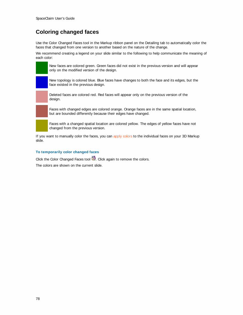
SpaceClaim User's Guide
78
Coloring changed faces
Use the Color Changed Faces tool in the Markup ribbon panel on the Detailing tab to automatically color the faces that changed from one version to another based on the nature of the change.
We recommend creating a legend on your slide similar to the following to help communicate the meaning of each color:
New faces are colored green. Green faces did not exist in the previous version and will appear only on the modified version of the design.
New topology is colored blue. Blue faces have changes to both the face and its edges, but the face existed in the previous design.
Deleted faces are colored red. Red faces will appear only on the previous version of the design.
Faces with changed edges are colored orange. Orange faces are in the same spatial location, but are bounded differently because their edges have changed.
Faces with a changed spatial location are colored yellow. The edges of yellow faces have not changed from the previous version.
If you want to manually color the faces, you can apply colors to the individual faces on your 3D Markup slide.
To temporarily color changed faces
Click the Color Changed Faces tool . Click again to remove the colors.
The colors are shown on the current slide.
79
Displaying your design The tools you use to customize the appearance of your design within the design window are found on SpaceClaim's Display tab. You can customize your design by modifying the style in which solids and edges are displayed, and by applying colors to the solids in your design. You can create layers to save different customizations and display characteristics. You can customize the workspace by creating windows or splitting the window to display multiple views of your design. You can also show or hide workspace tools. You can also configure the docking/detached location of all your workspace windows.
Display tools are grouped into the following Ribbon panels:
Orient Quickly display a particular view of your design.
Style Determine how the solids in your design will be displayed.
Window Create new design windows, split windows, and quickly switch between windows.
Show Display or hide tools in the design window.

SpaceClaim User's Guide
80
Graphics style Applying a graphics style to your design
Select an option from the Graphics Style tool from the Style ribbon group on the Display tab to display your design with that option.
You can select whichever option works best for you for any given task. You can display geometry with a shaded style, as wireframes, as wireframes with hidden lines displayed in light gray, and as wireframes with hidden lines removed. We recommend that you use the shaded style to most clearly indicate the difference between solids and surfaces.
Displaying edges
Use the Edges tool to customize which edges are displayed.
Select any combination of the following edge options from the Edges tool menu on the Display tab's Style ribbon panel. The edge selections apply to your entire design.
Select: To toggle the display of: Tangent Lines indicating tangent edges and edges that do not span a face Surface All edges on surfaces Solid All non-tangent edges on a solid Silhouette Lines indicating the silhouetted edges of all curved surfaces Layout Lines Layout lines on the layout planes shown in the Structure panel
Applying colors to your design
Use the Color tool to apply color to the solids, surfaces, and components in your design. You can also apply color to individual faces on a 3D markup slide. Sketches are drawn in the color of the active component.
Normally the colors of solids, surfaces, and components are determined by the layer they are on. However, you can override the layer colors.
To apply the layer color
1 Select the solid you want to color.
Assemblies imported from other modeling software can have only one color applied to the entire assembly.
2 Select Color by Layer from the Color tool on the Display tab's Style ribbon panel.
3 Select the layer from the Layer tool to place the solid on that layer and color it with the layer color.
To override the layer color for a solid
1 Select the solid you want to color.
Assemblies imported from other modeling software can have only one color applied to the entire assembly.
2 Select a color from the Color tool on the Display tab's Style ribbon panel.
If the color you want does not appear, select Custom Color and create the color.

Displaying your design
81
To override the layer and solid color for a face in a 3D markup slide
1 Select the face you want to color.
2 Select a color from the Color tool on the Display tab's Style ribbon panel.
If the color you want does not appear, select Custom Color and create the color.

SpaceClaim User's Guide
82
Layers Working with layers
SpaceClaim layers should be quite familiar to 2D CAD users. The concepts are simple. A layer can be thought of as a grouping mechanism for visual characteristics. Visual characteristics include visibility and color. Both of these can be locally overridden. Layers can be accessed in the Layer bar in the Style ribbon panel, or in the Layer Editor in the Structure panel.
Layers cannot be placed on layers. Objects are not automatically assigned by type. The default layer, Layer 0, cannot be renamed or deleted.
Layer bar
The Layer bar is located in the Style ribbon panel on the Display tab. The Layer bar displays the layer of the selected object. If no object is selected, it displays the current layer. It is blank if selected objects are on different layers. It also displays whether the selected object is colored based on its layer, or if its color is overridden. Layer visibility is also shown.
Select a different layer from the drop-down list to place the selected object(s) on that layer.
Layer Manager
Click the Layers tab on the Structure panel to display the Layer Manager. Use the Layer Editor to manipulate layer properties.
You can right-click to create new layers, rename layers, delete layers, activate a layer, show or hide a layer, set the color of objects on a layer, and set the selected color to the layer.
To place a solid, surface, or component on a layer
1 Select the solid, surface, or component.
2 Select the layer from the Layer tool on the Display tab's Style group to place the solid on that layer.

Displaying your design
83
Workspace windows Displaying your design in multiple windows
Use the New Window tool to create new workspace windows. Creating multiple windows allows you to set up several views of your design. Each window has a numbered tab at the bottom of the workspace.
To create a new workspace window
1 Select the New Window tool on the Display tab's Window ribbon panel.
A new tab appears at the bottom of your workspace and a number is appended to the design/drawing sheet/3D markup name.
Splitting the workspace window
Use the Split Window tool to divide the workspace window into multiple windows. Splitting the window allows you to see multiple views of your design simultaneously. Author's note: Include a still here of different views of the bracket.
Select how you want to split the workspace window from the Split Window tool menu on the Display tab's Window ribbon panel. The window is split based on your selection.
Switching between windows in the workspace
Use the Switch Window tool to select the window you want to display. This tool is useful if you have a large number of windows open. When you have fewer windows open, you will probably find it easier to select the window you want to display from the tabs at the bottom of the workspace.
Select the window you want to display from the Switch Window tool menu on the Display tab's Window ribbon panel.
Displaying workspace tools SpaceClaim offers the following tools to assist you while creating, editing, and detailing your designs:
The ruler is displayed at the lower right corner of the sketch grid.
Tool Guides appear in multi-step editing tools to help guide you through the editing process, and to provide greater flexibility when using the tool.
Tooltips appear when you however over tools, tool guides, and other icons. They briefly explain what will happen when you select the tool and provide some hints on how to use the tool.
The mini-toolbar appears near your cursor when you right-click. The contents of the mini-toolbar depend on the tool you are using.
The sketch grid appears in all the sketching tools. Displaying the sketch grid allows you to snap to grid lines and provides a visual cue to the orientation of your sketch within your design.

SpaceClaim User's Guide
84
To enable or disable workspace tools
Click the checkbox next to a tool in the Show ribbon panel on the Display tab to enable the tool. Click again to disable it.
You can also open the Application menu, click SpaceClaim Options, then enable or disable these tools in the Popular section.
85
Working with SpaceClaim documents
Designs, drawing sheets, and 3D markup When you create a new design, it appears on a tab in the workspace. Designs can contain drawing sheets, multiple windows, and 3D markups. Each drawing sheet and 3D markup appears on its own tab in the workspace. You can edit your design within the drawing sheet or on the design tab.
Click a tab to display that design/sheet/markup, or click the arrow icons to cycle between them. Click the x icon to close the tab.
To create a new design
Select New > New Design from the Application menu.
To open an existing design
select Open from the Application menu and select the file you want to open. The design and its windows, drawing sheets, and 3D markups open.
To save a design
Select Save or Save as from the Application menu.
If you select Save as, you can select a file type.
The XAML format saves only the solids in your design - planes, annotations, sketches, and other objects are not saved in this format.
When saving as an .STL file, the quality is based your graphics quality setting. We recommend setting the option to enable the highest possible graphics quality if you want your design to be useful as an SLA rapid prototype for form, fit, and function purposes.
To close a design
Make sure its window is active in the workspace, then select Close from the Application menu.

SpaceClaim User's Guide
86
Opening, importing, and exporting designs, drawing sheets, and 3D markups Use the Open command to open files created with SpaceClaim (.scdoc) or any other modeling application. Use the Save As command to export parts, assemblies, drawing sheets, and 3D markups to formats read by other applications. Your license type determines which of these actions are supported.
SpaceClaim supports ProE (.prt and .asm), Solidworks (.sldprt and .sldasm), Inventor (.ipt), CATIA version 4 (.model) and 5 (.CATPart and .CATProduct), Unigraphics (.prt), JT Open (.jt), Parasolid (.x_t and .x_b), ACIS (.sat and .sab) files, AutoCAD (.dwg, .dxf), VDA (.vda), STEP (.stp and .step), and IGES (.igs and .iges) files.
File type Supported actions ProE Open and insert parts and assemblies Solidworks Open and insert parts and assemblies Inventor Open and insert parts and assemblies CATIA version 4 and 5 Open and insert parts and assemblies
Export v5 parts and assemblies Unigraphics Open and insert parts and assemblies JT Open Open and insert parts and assemblies
Export parts and assemblies Parasolid Open and insert parts and assemblies
Export parts ACIS Open and insert parts and assemblies
Export parts AutoCAD Open and insert drawings, parts, and assemblies. Drawings can be
inserted as layouts or onto a drawing sheet. Export parts, assemblies, drawing sheets, and 3D markup slides
VDA Open and insert parts and assemblies Export parts
STEP Open and insert parts and assemblies Export parts
IGES Open and insert parts and assemblies Export parts
XAML, STL Export parts, assemblies, and drawing sheets Image (.jpg, .png, .bmp) Export parts, assemblies, drawing sheets, and 3D markup slides PowerPoint (.xps) Export 3D markup slides
To open or import a design
1 Select Open from the Application menu or click in the Quick Access toolbar.
2 Double-click the file you want to open.
The design is displayed in a new workspace window.
To export a design or 3D markup
1 Select Save as from the Application menu.
2 Select a file type.
The XAML format saves only the solids in your design - planes, annotations, sketches, and other objects are not saved in this format.

Working with SpaceClaim documents
87
When saving as an .STL file, the quality is based your graphics quality setting. We recommend setting the option to enable the highest possible graphics quality if you want your design to be useful as an SLA rapid prototype for form, fit, and function purposes.
Journals Journals record the actions you performed while creating your design.
Files are written to:
C:\Users\<User>\AppData\Roaming\SpaceClaim on Vista systems
C:\Documents and Settings\<User>\Application Data\SpaceClaim on XP systems
Design structure Each design document has a hierarchical structure, which is displayed in the Structure panel. Under the top-level design (your .scdoc file), components, solids, surfaces, planes, axes, and mating conditions. Create components to group geometry into assemblies. When you import a part or assembly, its structure appears in the Structure panel as a component, with any number of sub-components.
You can name each solid, surface, and component in the tree, import a file as a component, replace a component with another component, make components the active part to which new geometry will be added.

89
Customizing SpaceClaim You can customize SpaceClaim to best suit your working style. You can optimize performance, change the default units, modify the sketch grid, display or hide tools, customize the drawing and annotation styles, set advanced options, set snapping options, customize the ribbon and Quick Access bar, and configure the windows. You can also set the color scheme for the application and change the language of the interface. You can also customize your design and the design window.
Optimizing graphics and performance Depending on your needs, you can optimize SpaceClaim for speed or graphics quality.
To optimize performance
1 Select SpaceClaim Options from the Application menu to display the Popular options.
2 Move the Graphics Performance slider to the left to increase the speed of the application; slide it to the right to increase the quality of the graphics.
Increasing graphics quality may lower the SpaceClaim's responsiveness to actions in the Design window. If you notice a delay when selecting or working with other editing tools, modify this slider to increase application speed.
3 Click the Enable anti-aliasing checkbox if you want annotation text to be anti-aliased. Leaving this box unchecked will help speed performance.
Setting the color scheme You can modify the appearance of the SpaceClaim windows by selecting a color scheme and applying a color to the selected scheme.
To modify the color scheme
1 Select SpaceClaim Options from the Application menu to display the Popular options.
2 Select a theme from the Color scheme drop-down.
3 Select Custom Color from the Color scheme drop-down and mouse over the available colors to preview the change.
4 Click the color you want to use to modify the selected color scheme.
Changing the default units You can modify the default units shown when dimensioning your design. You can use the imperial or metric system, set the default unit of length, set how the units are displayed, and the symbol shown after the dimension value.
Most users prefer turning off the symbol and trailing zeros, and setting the number of decimal points to 1 if you are using millimeters as the default unit.
To change the default units
1 Select SpaceClaim Options from the Application menu to display the Popular options.
2 Click Units to display the unit settings.
3 Select whether you want to use metric or the imperial system from the Type drop-down.
SpaceClaim User's Guide
90
4 Select the default units to be used for length. (Angles are always shown in degrees.)
5 Select how you want dimension values displayed by checking or unchecking the Show symbol box.
6 Select whether you want to unit symbol displayed.
7 Click OK.
Modifying the sketch grid You can modify the size of the individual squares on the sketch grid and the size of the larger squares.
To modify the sketch grid
1 Select SpaceClaim Options from the Application menu to display the Popular options.
2 Click Sketch Grid to display the grid options.
3 Enter the size of each individual square in the Minor Grid Size field.
4 Enter the number of individual squares within the larger squares in the Minors in major field.
5 Click OK.
Displaying workspace tools SpaceClaim offers the following tools to assist you while creating, editing, and detailing your designs:
The ruler is displayed at the lower right corner of the sketch grid.
Tool Guides appear in multi-step editing tools to help guide you through the editing process, and to provide greater flexibility when using the tool.
Tooltips appear when you however over tools, tool guides, and other icons. They briefly explain what will happen when you select the tool and provide some hints on how to use the tool.
The mini-toolbar appears near your cursor when you right-click. The contents of the mini-toolbar depend on the tool you are using.
The sketch grid appears in all the sketching tools. Displaying the sketch grid allows you to snap to grid lines and provides a visual cue to the orientation of your sketch within your design.
To enable or disable workspace tools
Click the checkbox next to a tool in the Show ribbon panel on the Display tab to enable the tool. Click again to disable it.
You can also open the Application menu, click SpaceClaim Options, then enable or disable these tools in the Popular section.
Setting advanced options Additional options are available to specify how geometry is displayed in the Design window, allow you to view a journal of the actions that created a design, customize selection settings, and specify how files are imported and exported. You can also reset the configuration of the docking panels.
To set advanced options
1 Select SpaceClaim Options from the Application menu and select Advanced.
2 Modify the settings to specify how geometry is shown in the Design window and how drawings are imported and exported.
Copyright information
91
3 Click OK.
To customize how geometry is displayed in the Design window
1 Check the Enable view projection animation box to animate the steps when you select a view.
2 Check the Enable geometry animation box to animate all the steps when you select the Full Pull option to revolve, sweep, or blend your design.
3 Check the Enable loading of model in background box if you want to be able to orient large designs while they are loading.
4 Select when you want interim calculations performed when modifying solids from the Preview before modifying drop-down list. If calculations are turned off, previews appear as wireframes. Select:
Auto to allow SpaceClaim to determine when to perform interim calculations based on the size of the component and the capabilities of your graphics card.
On to always calculate previews.
Off to never calculate previews.
5 Check the Show cross sections box to display cross sections of solids with hatching.
To converge geometry automatically
If you want SpaceClaim to help you when you are moving solids together so that the edges (such as rounds) converge perfectly, click the Enable geometry convergence box. If this option is enabled, when you are moving solids together, SpaceClaim will display a progress bar as it performs the convergence steps.
To customize selection settings
1 Check the Show previous selections with prehighlight hint box to highlight all the geometry you last acted on that includes the selected vertex, edge, or face. If you click again with the Select tool, the previously selected group will be selected for you with that one click.
2 Enter the number of pixels that the cursor must be from a vertex, edge, or face to select it in the Hit radius field.
To review a journal of the actions that created a design
Check the Show Journal tab in the Ribbon box to save and play back a record of actions used to create a design.
To customize how files are imported and exported
1 Determine how you want DWG files imported into SpaceClaim. Select:
Open DWG - (Associated dimensions) to use SpaceClaim's translator. It will attach DWG dimensions to the geometry in your design.
Autodesk Real DWG to use Autodesk's translator. It will disconnect DWG dimensions from the geometry in your design.
2 Determine how you want DWG files exported from SpaceClaim. Select:
Open DWG - (Associated dimensions) to use SpaceClaim's translator. It will keep dimensions you created in SpaceClaim attached to the geometry in your design.
Autodesk Real DWG to use Autodesk's translator. It will disconnect dimensions from the geometry in your design.
Direct to AutoCAD (COM) if you are using a 64-bit machine. SpaceClaim will select this option for you if necessary.

SpaceClaim User's Guide
92
3 Select the version of ACIS you want to export to. You may want to adjust this option if you plan to use your SpaceClaim files with another piece of modeling software that is based on a different version of the ACIS geometry kernel.
To reset the layout of docking panels
To return the layout of the docking panels to the default configuration, click Reset Docking Layout.
Setting detailing options You can customize the style of your annotations in a single design document or set a custom style as the default for all designs. You can quickly customize the style to conform to ASME or ISO/JIS standards, or you can create a style by customizing note leaders, dimensions, and geometric tolerances.
To access annotation and drawing settings
Select SpaceClaim Options from the Application menu and click Detailing.
To customize annotations to conform to ASME or ISO/JIS standards
Click Reset to ASME Default to customize annotations for ASME systems.
Click Reset to ISO/JIS Default to customize annotations for ISO/JIS systems.
To customize annotations
1 Select whether you want to customize annotation for the current design document or all documents in the Detailing options for drop-down list.
2 Select the standard you want to use for projected views in drawings from the Default view projection drop-down list.
3 Enter the line length and arrow size for the cross-section indicators in drawings in the Section line arrow size and Section line length fields.
4 Enter the size of the circle that connects note leaders to faces in the Leader circle size field.
5 Enter the size of the arrowhead on note leaders in the Leader arrow width and Leader arrow length fields.
6 Enter the length of the line from the note text to the note leader arrow in the Leader shoulder length field.
7 Enter the size of the margin between the note text and the beginning of the note leader in the Leader textbox gap field.
8 Enter the size of the margin between geometry and the end of dimension lines in the Extension line gap field.
9 Enter the length that the dimension lines cross each other in the Extension line extend field.
10 Enter the length of the arrow that appears outside the dimension lines in the Dimension line extend field.
11 Select the style you want to use for the arrowheads on note leaders from the Default fill style drop-down list.
12 Select how you want to align the note leader text with the note leader line from the Default dimension text location drop-down list.
13 Select the font you want to use for geometric tolerance symbols from the Default GTOL font name drop-down list.
The two fonts in this drop-down list contain all the geometric tolerance symbols necessary. These symbols will be used as necessary in annotations, even when you select a different font for the annotation text.
Copyright information
93
14 Check the Enforce dimension line box to use the European standard of keeping the dimension line when the extension lines are shown.
15 Check the Horizontal dimension text box to keep all annotation text oriented horizontally.
16 Check the Override layer color for annotations box to set all annotation text to the color selected shown in the Annotation color control .
If you choose to override the layer color, select the color used for the override from the Annotation color control.
Changing the language The SpaceClaim interface is available in English and Japanese.
To change the language
1 Select SpaceClaim Options from the Application menu and click Advanced.
2 Select English or Japanese from the Language drop-down.
3 Click OK.
4 Exit SpaceClaim and restart it to display a different language.
Setting snapping options You can set snapping options for sketching and editing solids.
To set snapping options
1 Select SpaceClaim Options from the Application menu and click Snap.
2 Check each box next to the snapping options you want to use. Uncheck boxes to disable snapping in that situation.
3 Click OK.
Setting file paths To set common file locations to speed searching for your designs
1 Select SpaceClaim Options from the Application menu and click Files.
2 Add a file path.
3 Order file paths.
4 Click OK.
Customizing the ribbon and Quick Access toolbar The Quick Access toolbar (QAT) is located on the title bar. The Ribbon is the menubar that contains all the tools in groups. You can add or remove tools from this toolbar and control the placement and display of the Ribbon.
SpaceClaim User's Guide
94
To perform a task
1 Select SpaceClaim Options from the Application menu and click Customize.
2 Select the ribbon panel that contains the tool you want to include in the QAT from the drop-down menu.
3 Click the tool you want to include and click Add.
4 Click OK.
Configuring SpaceClaim windows SpaceClaim has several docking windows that are initially docked along the left side of the application. You can minimize these panels, detach them, or dock them to different sides of the application. You can also dock and detach your design windows.
To minimize a panel
Click the thumbtack icon to minimize the docked panel. Mousing over a minimized panel expands the panel while the cursor is over it. Once the cursor leaves the expanded panel, it returns to its minimized state.
To maximize a panel
Click the thumbtack icon to "stick" the panel to the application window.
To detach a panel or window
Drag a panel by its title bar to detach it. Drag a design window by its tab to detach it.
To dock a panel or window
Drag a panel or window by its title bar or tab. As you move the panel or window over the application, icons indicate possible docking positions. Mouse over an icon to preview the docked location. Click to dock the panel to that location.
To return docked panels to their default layout
1 Select SpaceClaim Options from the Application menu and select Advanced.
2 Click Reset Docking Layout.
3 Click OK.


![Formless: A User's Guide, [excerpt] A User's Guide to Entropy ...](https://static.fdocuments.in/doc/165x107/586b77ce1a28ab9c7d8bebd4/formless-a-users-guide-excerpt-a-users-guide-to-entropy-.jpg)