
Sp Column Presentation
27
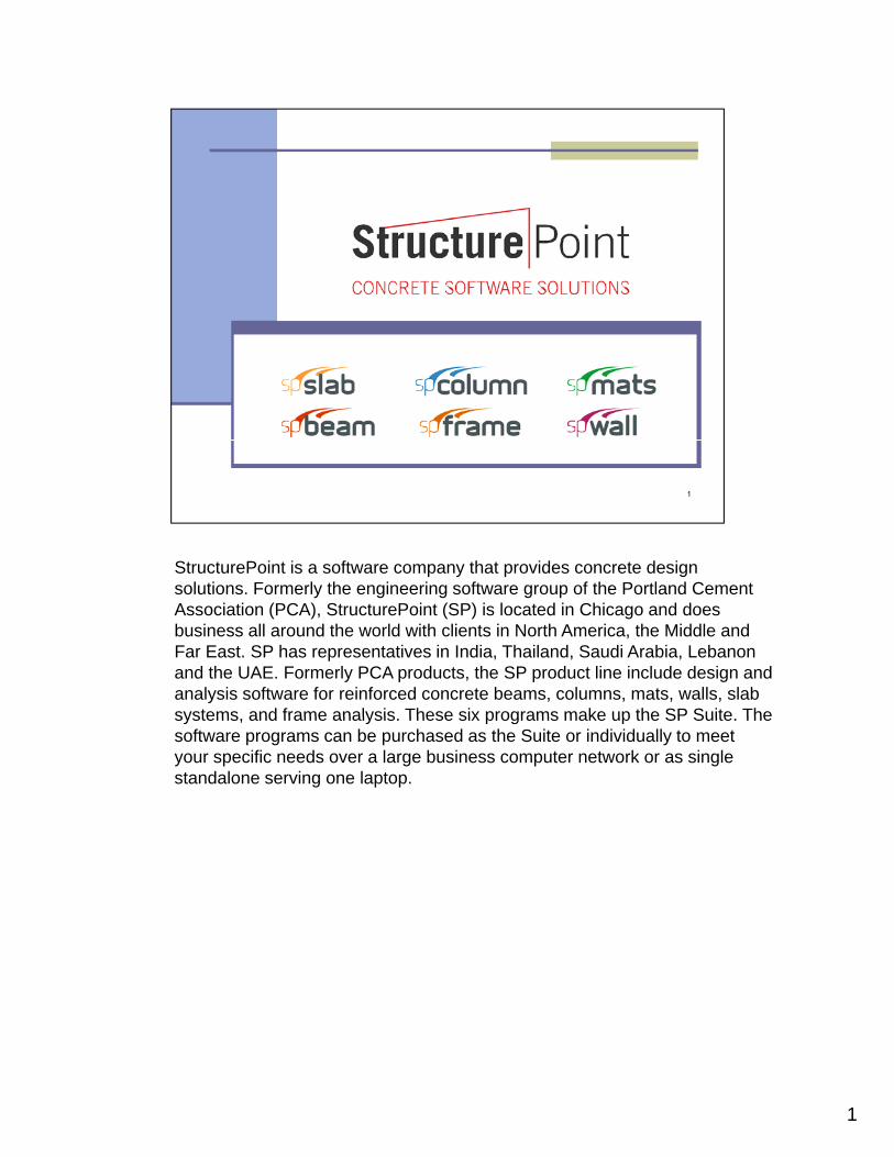
StructurePoint is a software company that provides concrete design solutions. Formerly the engineering software group of the Portland Cement Association (PCA), StructurePoint (SP) is located in Chicago and does business all around the world with clients in North America, the Middle and Far East. SP has representatives in India, Thailand, Saudi Arabia, Lebanon and the UAE. Formerly PCA products, the SP product line include design and analysis software for reinforced concrete beams, columns, mats, walls, slab systems and frame analysis These six programs make up the SP Suite The systems, and frame analysis. These six programs make up the SP Suite. The software programs can be purchased as the Suite or individually to meet your specific needs over a large business computer network or as single standalone serving one laptop. 1
description
column
Transcript of Sp Column Presentation
StructurePoint is a software company that provides concrete design solutions. Formerly the engineering software group of the Portland Cement Association (PCA), StructurePoint (SP) is located in Chicago and does business all around the world with clients in North America, the Middle and Far East. SP has representatives in India, Thailand, Saudi Arabia, Lebanon and the UAE. Formerly PCA products, the SP product line include design and analysis software for reinforced concrete beams, columns, mats, walls, slab systems and frame analysis These six programs make up the SP Suite Thesystems, and frame analysis. These six programs make up the SP Suite. The software programs can be purchased as the Suite or individually to meet your specific needs over a large business computer network or as single standalone serving one laptop.
1

The SP Suite has the capability to design an entire concrete structure from foundation to roof. These programs are based on the methods, equations, and procedures found in ACI 318 and CSA 23.3 in English and Metric units. Due to the schedule of updating the concrete codes, the five code driven software are given a major upgrade every three years along with annual updates. The SP suite is designed to allow the user to work quickly, simply and accurately. In essence, you can get to a final design solution fast with confidence and little training and wasted timeconfidence and little training and wasted time.
2

Use of the StructurePoint software can be found in many publications regarding reinforced concrete design and analysis.
3

spColumn has been the flagship of the SP Software Suite. It is a reputable program used for the design and investigation of rectangular, round, and irregular concrete columns. In addition to allowing any section geometry, spColumn is capable of analyzing any reinforcing arrangement. After taking the section material properties, geometry, and design specifications the program produces the corresponding interaction diagrams and failure surfaces along with a number of useful design results
4

spColumn’s many design options allow it to produce accurate results for any situation. Whether working within the US or Canadian code the program can handle both English and metric units. spColumn does not limit the user to just the most recent code release either. This feature allows the user to move through time and determine if a column designed to ACI 318-05 was adequate and then with the click of the mouse determine if it is compliant with the 2008 code requirements. Beyond choosing the code edition, the program allows for both the analysis and the design of columns subjected toprogram allows for both the analysis and the design of columns subjected to axial loading, uniaxial and biaxial bending as well as the consideration of slenderness. All of these program options add up to one thing; spColumn is universally applicable and regardless of the project spColumn will be a very useful tool.
5

One of the most useful capabilities of this program is its ability to perform slenderness column/wall analysis and moment magnification. The moment magnification can account for either sway or nonsway frames and will perform a series of calculations and checks to ensure that the column is properly designed. This figure demonstrates the methodology used to for consideration of slender columns within ACI 318-08/11.
6

This complexity of slenderness boils down to four inputs by the user: The column to be designed, the surrounding columns, the surrounding beams, and slenderness factors. For simplicity, spColumn allows for the user to define their own value for the effective length factor k, otherwise spColumn will calculate the exact value of for k for you.
7

The user options continue with allowing the type of section confinement to be specified. spColumn acccomodates tied confinement, spiral confinement, and user inputted confinement. These options dictate what strength (phi) factors are used in the section design and analysis.
There are four design criteria that the user can specify. The first is column type. Choosing to design the column as either a structural or architectural column will pre-set the range of reinforcing ratio. On the other hand, i di ti d fi d l t ill ll th t ll dj tindicating a user-defined column type will allow the user to manually adjust the minimum and maximum reinforcing ratios. The bar selection option allows the user to indicate to the program whether the ideal reinforcing is a minimum number of bars or a minimum area of steel. The user can also specify the clear spacing between bars as well as the ratio of provided to required reinforcement.
8

spColumn will design for concrete and steel material properties in the ranges available to the construction markets. Each property can be input individually, but for your convenience when the concrete or steel strength is entered, the rest of the variables will be automatically calculated. The program also handles precast models designed according to the CSA code.
9

With the material properties defined, the next step is to create the section dimensions. For the investigation mode this is straight forward. The user can choose between a rectangular section, a circular section, or their own specified irregular section.
For column design, the section input becomes little more involved. spColumn designs a column by starting with the smallest cross section allowable as specified by the user. The program then steps through each possible cross
ti t d fi d i t til it bl l i dsection at user defined increments until a suitable column size and reinforcement is determined. This process is the same for both rectangular and circular columns.
10

As mentioned, spColumn is capable of analyzing irregular sections as defined by the user. There are two methods to create an irregular section with the first one being a graphical creation tool. This picture is the irregular section editor. The section editor functions by creating a grid or mesh, of which the user can specify the spacing, and drawing lines between grid nodes. One of the foremost reasons for the irregular section editor is to allow for the inclusion of a void or opening within the column. These voids are created in the same way as the rest of the sectioncreated in the same way as the rest of the section.
11

The irregular section editor is not limited to just rectangular sections or the tedious method of approximating circular sections with straight lines. Circular sections that are defined before entering the section editor will be carried into the section editor as exact circles. From here the section can be edited and voids can be created to model the space where a steel I beam is included as shown.
12

If a section is more complicated than the irregular section editor can handle, the program can model sections by importing a table of section data points. The spColumn software includes a design assistant excel worksheet that creates the geometry of 7 different sections based on the users specifications. These 7 sections are based on the program’s included examples and the default dimensions are set to these examples. If these sections are not exactly the required section, any section can be manually created using this section input method Microsoft Excel or any othercreated using this section input method. Microsoft Excel or any other spreadsheet editor capable of performing this function.
13
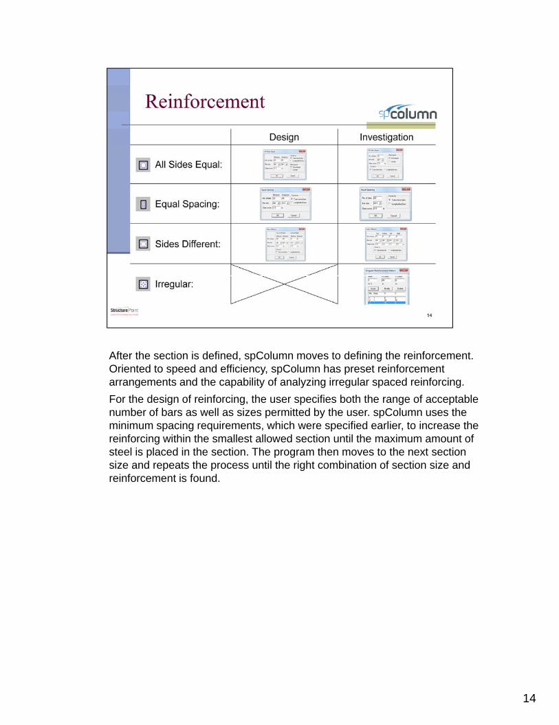
After the section is defined, spColumn moves to defining the reinforcement. Oriented to speed and efficiency, spColumn has preset reinforcement arrangements and the capability of analyzing irregular spaced reinforcing.
For the design of reinforcing, the user specifies both the range of acceptable number of bars as well as sizes permitted by the user. spColumn uses the minimum spacing requirements, which were specified earlier, to increase the reinforcing within the smallest allowed section until the maximum amount of t l i l d i th ti Th th t th t tisteel is placed in the section. The program then moves to the next section
size and repeats the process until the right combination of section size and reinforcement is found.
14

Similar to creating irregular sections, spColumn can define reinforcing using the irregular section editor. This ability allows reinforcing to be assigned using the cursor or, for the more complex reinforcing, by defining the exact coordinates. Assigning reinforcing in this manner is required for irregular sections, but it can also be used for rectangular or circular sections.
15

Reinforcing can also be assigned using the same method of inputting a data table of reinforcing locations. If the section was defined in the same manner, this may be the easiest way input the reinforcing. The same 7 design assistant worksheets provided for sections will create the reinforcing placement.
16

spColumn has many load options available to the user. Loads can be entered as factored loads or service loads depending on what the user is provided. The service loads and axial loads option are intended more for investigative purposes.
17
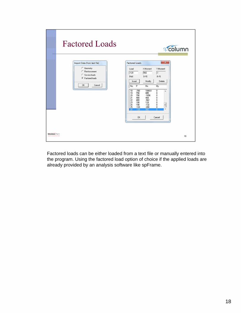
Factored loads can be either loaded from a text file or manually entered into the program. Using the factored load option of choice if the applied loads are already provided by an analysis software like spFrame.
18

Similar to the factored loads, service loads can be loaded from a text file or inputted manually. The choice between inputting the loads as service or factored loads is entirely based on what values the engineer is provided and his or her preference.
19
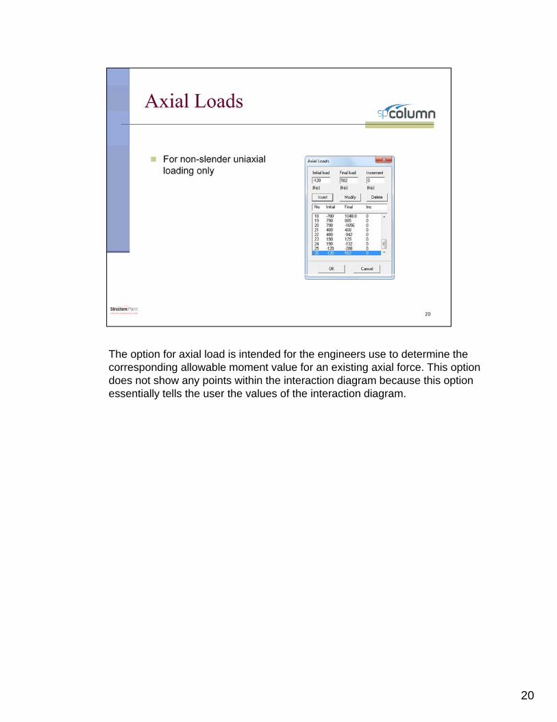
The option for axial load is intended for the engineers use to determine the corresponding allowable moment value for an existing axial force. This option does not show any points within the interaction diagram because this option essentially tells the user the values of the interaction diagram.
20
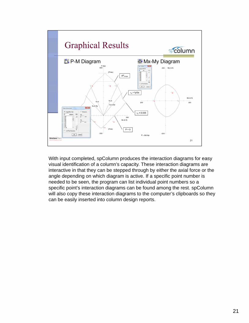
With input completed, spColumn produces the interaction diagrams for easy visual identification of a column’s capacity. These interaction diagrams are interactive in that they can be stepped through by either the axial force or the angle depending on which diagram is active. If a specific point number is needed to be seen, the program can list individual point numbers so a specific point’s interaction diagrams can be found among the rest. spColumn will also copy these interaction diagrams to the computer’s clipboards so they can be easily inserted into column design reportscan be easily inserted into column design reports.
21

The program can also provide the nominal interaction diagram to show the column’s capacity before it is factored.
22

One unique feature of spColumn is its ability to superimpose these interaction diagrams on each other. The superimposing feature might have its most useful application in comparing different section types. The column being analyzed is represented by the solid line while the superimposed interaction diagram is represented by the dotted line. In this case, the original column was found to be underdesigned. The superimposed interaction diagram demonstrates that this alternate design is acceptable for the current loading as well as how much more capacity is achieved than withthe current loading as well as how much more capacity is achieved than with the original design.
23

In addition to producing the graphical results, spColumn outputs a text report of the design or analysis process. The report is designed to provide all the necessary information an engineer needs to evaluate the designed column, but at the same time allow the user to easily identify the critical load combinations. In this example Factored Loads number 4, 9, 10, and 20 exceed the section capacity and require the column to be revised.
24

The batch mode feature of the program is a great automation tool to streamline the column investigation process. Intended for integration with 2D/3D structural analytical models, the batch mode takes text files that include all of the column properties and loading conditions and produces results like interaction diagrams, interaction diagram data, column section dxf files, and all graphical results. The process of setting up the batch files to run is where the time in this process is invested, but with intelligent methods the total required time can be greatly reducedtotal required time can be greatly reduced.
25

The text files that are used by the batch mode are spColumn Text Input (CTI) files. This is an example of what one looks like. This file contains all the information that spColumn needs to produce results. Luckily, there is no need to create these CTI files from scratch. Start by creating a typical column using the spColumn program. When everything has been defined, save the file as a CTI file. This will save the format which can then be used as a template for all future CTI files. Also, the spColumn user manual has a detailed section designed to help users modify and develop their CTI files fordetailed section designed to help users modify and develop their CTI files for batch mode analysis. Many users devised in-house scripts to further leverage this feature and connect with other software tools and BIM programs.
26

StructurePoint would be glad to hear from you and receive your feed back as well as answer any questions regarding the program features, capabilities, price, and licensing options
58