
sox5050 - HP Archivehparchive.com/Manuals/HP-410C-Manual.pdf · The Hewlett-Packard Model 4l0C...
63
TM 11-6625-1614-15 DEPARTMENT OF THE ARMY TECHNICAL MANUAL ORGANIZATIONAL, DS, GS, AND DEPOT MAINTENANCE MANUAL HEWLETT-PACKARD ELECTRONIC VOLTMETER MODEL 410C This copy IS a reprint which includes current pages from Change 1. HEADQUARTERS, DEPARTMENT OF THE ARMY AUGUST 1967
-
Upload
dangkhuong -
Category
Documents
-
view
218 -
download
0
Transcript of sox5050 - HP Archivehparchive.com/Manuals/HP-410C-Manual.pdf · The Hewlett-Packard Model 4l0C...
TM 11-6625-1614-15D E P A R T M E N T O F T H E A R M Y T E C H N I C A L M A N U A L
ORGANIZATIONAL, DS, GS,
AND DEPOT MAINTENANCE MANUAL
HEWLETT-PACKARD
ELECTRONIC VOLTMETER
MODEL 410C
T h i s c o p y I S a r e p r i n t w h i c h i n c l u d e s c u r r e n t
p a g e s f r o m C h a n g e 1 .
H E A D Q U A R T E R S , D E P A R T M E N T O F T H E A R M Y
AUGUST 1967
TM 11-6625-1614-15
WARNINGDANGEROUS VOLTAGES
EXIST IN THIS EQUIPMENT
Be careful when working on the power supplies
and the i r c i rcu i t s , o r on the 115- or 230-vol t
a c l i n e c o n n e c t i o n s .
DON’T TAKE CHANCES!

This manual contains copyrighted material prepared by the Hewlett-Packard Co.
TM 11-6625-1614-15
TECHNICAL MANUAL HEADQUARTERSDEPARTMENT OF THE ARMY
No. 11-6625-1614-15) W A S H I N G T O N, DC, 28 August 1 9 6 7
ORGANIZATIONAL, DS, GS, AND DEPOT MAINTENANCE MANUAL
HEWLETT–PACKARD ELECTRONIC VOLTMETERMODEL 410C
(NSN 6625-00-969-4105)
Section
I GENERAL1-A.1.1-A.2.1-A.3.1-A.4.1-A.5.1-A.6.1-1.1-4.
INFORMATION -------------------------------------------------------------------------------------------Scope --------------------------------------------------------------------------------------------------------Index of Publications ------------------------------------------------------------------------------------Maintenance Forms, Records, and Reports ---------------------------------------------------------Reporting Errors and Recommending Improvements --------------------------------------------Reporting Equipment Improvement Recommendations (EIR)---------------------------------Administrative Storage ----------------------------------------------------------------------------------Description -------------------------------------------------------------------------------------------------Accessories Available ------------------------------------------------------------------------------------
II INSTALLATION ----------------------------------------------------------------------------------------------------------2-1. Inspection ---------------------------------------------------------------------------------------------------2-3. Installation -------------------------------------------------------------------------------------------------2-5. Rack Mounting --------------------------------------------------------------------------------------------2-9. Three - Conductor Power Cable ----------------------------------------------------------------------2-12. Primary Power Requirements --------------------------------------------------------------------------2-14. Repackaging for Shipment ------------------------------------------------------------------------------
III OPERATION ---------------------------------------------------------------------------------------------------------------3-1. Introduction ------------------------------------------------------------------------------------------------3-3. Adjustment of Mechanical Zero----------------------------------------------------------------------3-5. Front and Rear Panel Description ---------------------------------------------------------------------3-7. Operating Procedures ------------------------------------------------------------------------------------3-9. DC Voltage Measurements (Figure 3-2)-------------------------------------------------------3-11. DC Current Measurements (Figure 3-3)-------------------------------------------------------3-13. AC Voltage Measurements (Figure 3-4) -------------------------------------------------------3-15. Precautions When Measuring AC Voltage ----------------------------------------------------3-28. Negative Pulses --------------------------------------------------------------------------------------------3-31. Measuring Resistance (Figure 3-7) --------------------------------------------------------------------3-33. Measuring DC Nano-Ampere Current (Figure 3-8) -----------------------------------------------
IV THEORY OF OPERATION ---------------------------------------------------------------------------------------------4-1. Overall Description ---------------------------------------------------------------------------------------4-4. Circuit Description ---------------------------------------------------------------------------------------4-5. Input Network ---------------------------------------------------------------------------------------4-16. Modulator - Demodulator ------------------------------------------------------------------------4-23. The Feedback Network ----------------------------------------------------------------------------4-27. Power Supply ----------------------------------------------------------------------------------------
V MAINTENANCE ----------------------------------------------------------------------------------------------------------5-1. Introduction -----------------------------------------------------------------------------------------------5-3. Test Equipment Required -------------------------------------------------------------------------------5-5. Performance Checks -------------------------------------------------------------------------------------
Change
Page
1-11-11-11-11-21-21-21-41-5
2-12-12-12-12-12-12-2
3-13-13-13-13-13-13-13-13-13-43-43-4
4-14-14-14-14-14-24-25-15-15-15-1
i

TM 11-6625-1614-15
Section
Number
1-1.3-1.5-1.5-2.5-3.5-4.5-5.5-6.5-7.5-8.5-9.5-10.
Number
1-1.2-1.2-2.2-3.2-4.3-1.3-2.3-3.3-4.3-5.3-6.3-7.3-8.4-1.4-2.4-3.
5 - 7 .5 - 9 .5 - 1 0 .5 - 1 3 .5 - 1 6 .5 - 1 7 .5 - 2 1 .5 - 2 2 .5 - 2 6 .5 - 2 8 .5 - 2 9 .5 - 3 0 .5 - 3 1 .5 - 3 3 .5 - 3 4 .5 - 3 5 .5 - 3 6 .5 - 4 5 .5 - 4 8 .
Alternate Voltage Source --------------------------------------------------------------------------Mechanical Meter Zero ----------------------------------------------------------------------------DC Voltmeter OWration --------------------------------------------------------------------------DC Ammeter Operation ---------------------------------------------------------------------------Ohmmeter Operation ------------------------------------------------------------------------------Amplifier Operation --------------------------------------------------------------------------------DC Amplifier Output Impedance Check -------------------------------------------------------AC Voltmeter Operation --------------------------------------------------------------------------
Adjustment and Calibration Prmedure --------------------------------------------------------------Chopper Frequency Adjust -----------------------------------------------------------------------Power Supply Adjustment ------------------------------------------------------------------------DC Zero Adjustment and Bias -------------------------------------------------------------------DC Amplifier Output Adjust ---------------------------------------------------------------------Ohms Adjust (R3)-----------------------------------------------------------------------------------AC Zero Adjust -------------------------------------------------------------------------------------AC Full Scale Adjust (.5 V Range) --------------------------------------------------------------
Troubleshooting Procedure -----------------------------------------------------------------------------Servicing Etched Circuit Boards -----------------------------------------------------------------Chopper, Assembly Installation -----------------------------------------------------------------
LIST OF TABLES
Specifications ------------------------------------------------------------------------------------------------------------Possible Eror When Measuring Voltage of Complex Waveforms -------------------------------------------Recommended Test Equipment -------------------------------------------------------------------------------------DCV Accuracy Test ----------------------------------------------------------------------------------------------------DCV Input Resistance Test -------------------------------------------------------------------------------------------DCA Accuracy Test ----------------------------------------------------------------------------------------------------DeletedAC Accuracy Test ------------------------------------------------------------------------------------------------------Power Supply Test -----------------------------------------------------------------------------------------------------AC Full Scale Adjust --------------------------------------------------------------------------------------------------Front Panel Troubleshooting Prmedure --------------------------------------------------------------------------Troubleshooting Prwedure ------------------------------------------------------------------------------------------
LIST OF ILLUSTRATIONS
The Combining Case . . . . . . . . . . . . . . . . . . . . . . . . . . . . . . . . . . . . . . . . . . . . . . . . . . . . . . . . . . . . . . . . . . . . . . . . . . . . . . . . . . . . . . . . . . . . . . . . . . .Steps to Place Instrument in Combining Case--------------------------------------------------------------------Adaptor Frame Instrument Combination . . . . . . . . . . . . . . . . . . . . . . . . . . . . . . . . . . . . . . . . . . . . . . . . . . . . . . . . . . . . . . . . . . . . . . . . .TWO Half Modules in Rack Adaptor -------------------------------------------------------------------------------Front and Rear Panel Controls --------------------------------------------------------------------------------------DC Voltage Measurements . . . . . . . . . . . . . . . . . . . . . . . . . . . . . . . . . . . . . . . . . . . . . . . . . . . . . . . . . . . . . . . . . . . . . . . . . . . . . . . . . . . . . . . . . . .DC Current Measurements . . . . . . . . . . . . . . . . . . . . . . . . . . . . . . . . . . . . . . . . . . . . . . . . . . . . . . . . . . . . . . . . . . . . . . . . . . . . . . . . . . . . . . . . . . .AD Voltage Measurements . . . . . . . . . . . . . . . . . . . . . . . . . . . . . . . . . . . . . . . . . . . . . . . . . . . . . . . . . . . . . . . . . . . . . . . . . . . . . . . . . . . . . . . . . . .Maximum AC Voltage Chart for 11036A Probe . . . . . . . . . . . . . . . . . . . . . . . . . . . . . . . . . . . . . . . . . . . . . . . . . . . . . . . . . . . . . . . . .Graph Used in Calculation of Pulse Voltage Readings . . . . . . . . . . . . . . . . . . . . . . . . . . . . . . . . . . . . . . . . . . . . . . . . . . . . . . . . .Resistance Measurements . . . . . . . . . . . . . . . . . . . . . . . . . . . . . . . . . . . . . . . . . . . . . . . . . . . . . . . . . . . . . . . . . . . . . . . . . . . . . . . . . . . . . . . . . . . . .DC Nano-Ampere Current Measurements . . . . . . . . . . . . . . . . . . . . . . . . . . . . . . . . . . . . . . . . . . . . . . . . . . . . . . . . . . . . . . . . . . . . . . . .Block Diagram, Model 410C . . . . . . . . . . . . . . . . . . . . . . . . . . . . . . . . . . . . . . . . . . . . . . . . . . . . . . . . . . . . . . . . . . . . . . . . . . . . . . . . . . . . . . . . .Modulator - Demodulator Mechanical Analogy . . . . . . . . . . . . . . . . . . . . . . . . . . . . . . . . . . . . . . . . . . . . . . . . . . . . . . . . . . . . . . . .Simplified Schematic, DC Current Measurement ---------------------------------------------------------------
Page
5- 15-15-15-25-45-45-55-55-85-85-95-105-105-115-125-125-125-145-15
1-33-35-05-25-35-3
5-65-95-135-165-17
The Model 410C Electronic Voltmeter
Page
1-02-02-02-12-23-23-53-63-73-83-93-103-114-04-04-3
ii
TM 11-6625-1614-15
Number
4-4.4-5.4-6.5-1.5-2.5-3.5-4.5-5.5-6.5-6.15-7.5-8.5-9.5-10.5-11.5-12.5-13.5-14.
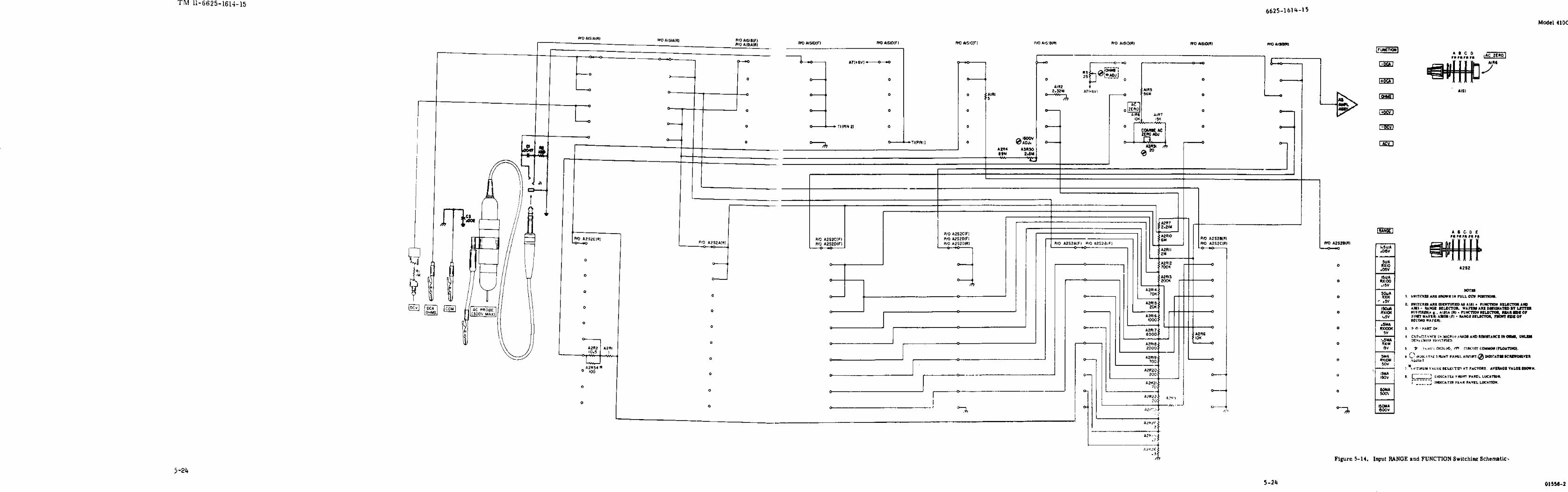
Simplified Schematic, DC Voltage Measurements --------------------------------------------------------------Simplified Schematic, Resistance Measurement -----------------------------------------------------------------Simplified Schematic, AC Voltage Measurement ---------------------------------------------------------------Alternate Voltage Source ---------------------------------------------------------------------------------------------DC Ammeter Operation ----------------------------------------------------------------------------------------------High Frequency Response Test --------------------------------------------------------------------------------------Low Frequency Response Test ---------------------------------------------------------------------------------------Troubleshooting Tree --------------------------------------------------------------------------------------------------A4 Chopper Assembly Installation ---------------------------------------------------------------------------------Chopper Frequency Adjust Setup -----------------------------------------------------------------------------------Power Supply Measurements ----------------------------------------------------------------------------------------Power Supply Schematic ----------------------------------------------------------------------------------------------Typical Amplifier Waveforms ---------------------------------------------------------------------------------------Amplifier Schematic---------------------------------------------------------------------------------------------------Model 11036A AC Probe Exploded --------------------------------------------------------------------------------Model l1036A Probe Schematic ------------------------------------------------------------------------------------RANGE and FUNCTION Switching (Pictorial) -----------------------------------------------------------------Input RANGE and FUNCTION Switching Schematic ---------------------------------------------------------
Page
4-44-54-65-15-35-55-65-145-155-16.15-175-195-205-215-225-225-235-24
i i i
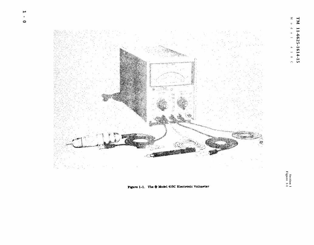
Figure 1-1.
TM
11-6625-1614-15
Mo
de
l
41
0C
Section
IF
igure 1-1
1-
0

TM 11-6625-1614-15
SECTION IGENERAL INFORMATION
1-A.1. Scopea. This manual includes installation and operation
instructions and covers operator’s, organizational,direct support (DS), general support (GS), and depotmaintenance. It describes Hewlett-Packard (Federalsupply code 28480) Electronic Voltmeter Model 410C.This manual applies to equipments with serial num-bers prefixed by 433 and serial number 532-03701and higher. If the first three digits on your instru-ment are 550, refer to figure 5-10, note 14 for thechange in equipments of this serial prefix.
b. A basic issue iterns list for this equipment isnot included as part of this manual.
1-A.2. Index of PublicationsRefer to the latest issue of DA Pam 310-4 to deter-mine whether there are new editions, changes, or ad-ditional publications pertaining to the equipment.
1-A.3. Maintenance Forms, Records,and Reports
a. Reports of Maintenance and UnsatisfactoryEquipment. Department of the Army forms andprocedures used for equipment maintenance will bethose prescribed by TM 38-750, The Army Mainte-nance Management System.
b. Report of Item and Packaging Discrepancies.Fill out and forward SF 364 (Report of Discrepancy(ROD) ) as prescribed in AR 735-1l-2/DLAR 4140.55/NAVMATINST 4355.73/AFR 400.54/MCO4430.3E.
c. Discrepancy in Shipment Report (DISREP)(SF361). Fill out and forward Discrepancy in Ship-ment Report (DISREP) (SF 361) as prescribed in AR
55-38/NAVSUPINST 4610.33B/AFR 75-18/MCOP4610.19C and DLAR 4500.15.
1-A.4. Reporting Errors and Recoin.mending ImprovementsYou can help improve this manual. If you find anymistakes or if you know of a way to improve the pro-cedures, please let us know. Mail your letter, DAForm 2028 (Recommended Changes to Publicationsand Blank Forms), direct to Commander, US ArmyCommunications and Electronics Materiel Readi-ness Command, ATTN: DRSEL-ME-MQ, FortMonmouth, NJ 07703. A reply will be furnished toyou.
1-A.5. Reporting Equipment Improve.ment Recommendations (EIR)If your Electronic Voltmeter needs improvement, letus know. Send us and EIR. You, the user are the onlyone who can tell us what you don’t like about yourequipment. Let us know why you don’t like the de-sign. Tell us why a procedure is hard to perform. Putit on an SF 368 (Quality Deficiency Report). Mail itto Commander, US Army Communications and Elec-tronics Materiel Readiness Command, ATTN: DRS-EL-ME-MQ, Fort Monmouth, NJ 07703. We’llsend you a reply.
1-A.6. Administrative StorageAdministrative storage of this equipment consists ofcovering the equipment with heavy paper taped in away to prevent entry of dust particles. If environmentis humid, use bags of dessicant inside the papercovering.
Change 1 1-1/ (1-2 Blank)


Table 1-1.
TM 11-6625-1614-15Section ITable 1-1
Model 410C
01556-2
1-3

TM 11-6625-1614-15 Model 410C
1-1. DESCRIPTION.
1-2. The Hewlett-Packard Model 4l0C Electronic Voltmeter can be
used to measure DC voltage and DC current; AC voltage and
resistance. Positive and negative DC voltages from 10 millivolts
to 1500 volts and positive and negative DC currents from 1.5
microamperes to 150 milliamperes can be measured full scale.
Resistance from 10 ohms to 10 megohms full scale can be measured
with an accuracy of ±5% of reading at midscale; resistance from
0.2 ohms to 500 megohms can be measured with reduced accuracy.
The Model 410C Electronic Voltmeter is shown in Figure 1-1; the
specifications are given in Table 1-1.
1-3. With the Model 11036A detachable AC Probe, the Voltmeter
can be used to measure AC voltage from 20 cps to 700 Mc. From
20 cps to 100 MC) AC voltage from 0.5 to 300 volts can be measured;
from 100 Mc to 700 Mc, refer to Figure 3-5 for maximum AC voltage
that can be applied to the AC Probe. For additional information
on the AC Probe, refer to Paragraph 1-8.
1-4

Model 410C TM 11-6625-1614-15
1-4. ACCESORIES AVAILABLE .
1-5. MODEL 11036A AC PROBE. This accessory, when used with the
Model 410C, permits AC voltage measurements from 0.5 volt rms
to 300 volts rms, full scale over a frequency range of 20 cps to
700 Mc. Reference calibration accuracy at 400 cps (sinusoidal)
is ±3% of full scale. Frequency response is ±10% from 20 cps to
700 Mc, with indications obtainable to 3000 Mc. Frequency
response at 100 Mc is within ±2%. The Model 110364 responds to
the positive-peak-above-average value of the signal applied. The
Model 410C is calibrated to read in RMS volts, for sine wave
inputs .
1 - 5

Model 410C
TM 11-6625-1614-15Section IIFigures 2-l and 2-2
Figure 2-1. The Combining Case
Figure 2-2. Steps to Place Instrument in Combining Case
2-0 01556-1

TM 11-6625-1614-15Model 410C Section II
Paragraphs 2-1 to 2-13
SECTION IIINSTALLATION
.
2-1. INSPECTION.
2-2. ‘This instrument was carefully inspected bothmechanically and electrically, before shipment. Itshould be physically free of mars or scratches and inperfect electrical order upon receipt. To confirmthis, the instrument should be inspected for physicaldamage in transit. Also, check for supplied acces-sories, and test the electrical performance of the in-strument using the procedure outlined in Paragraph5-5 Performance Checks. If there is anydamage or deficiency, refer toparagraph 1-A.3.2-3. INSTALLATION.
2-4. The Model 410C is transistorized except forone vacuum tube and requires no special cooling.However, the instrument should not be operated wherethe ambient temperature exceeds 55° C (140° F).
2-5. RACK MOUNTING.
2-6. The Model 410C is a submodular unit designedfor bench use. However, when used in combinationwith other submodular units, it can be bench and/orrack mounted. The Combining Cases and AdapterFrame are designed specifically for this purpose.
2-7. MODELS 1051A AND 1052A COMBINING CASES.The Combining Cases are full-module unita whichaccept various combinations of submodular units.Beinga full width unit, it can either be bench or rackmounted. An illustration of the Combining Case isshown in Figure 2-1. Instructions for installing theModel 410C are shown in Figure 2-2.
2-8. RACK ADAPTER FRAME ( Part No. 5060-0797). The adapter frame is a rack mounting framethat accepts various combinations of submodularunits. It can be rack mounted only. An illustrationof the adapter frame is given in Figure 2-3. Instruc-tions are given below.
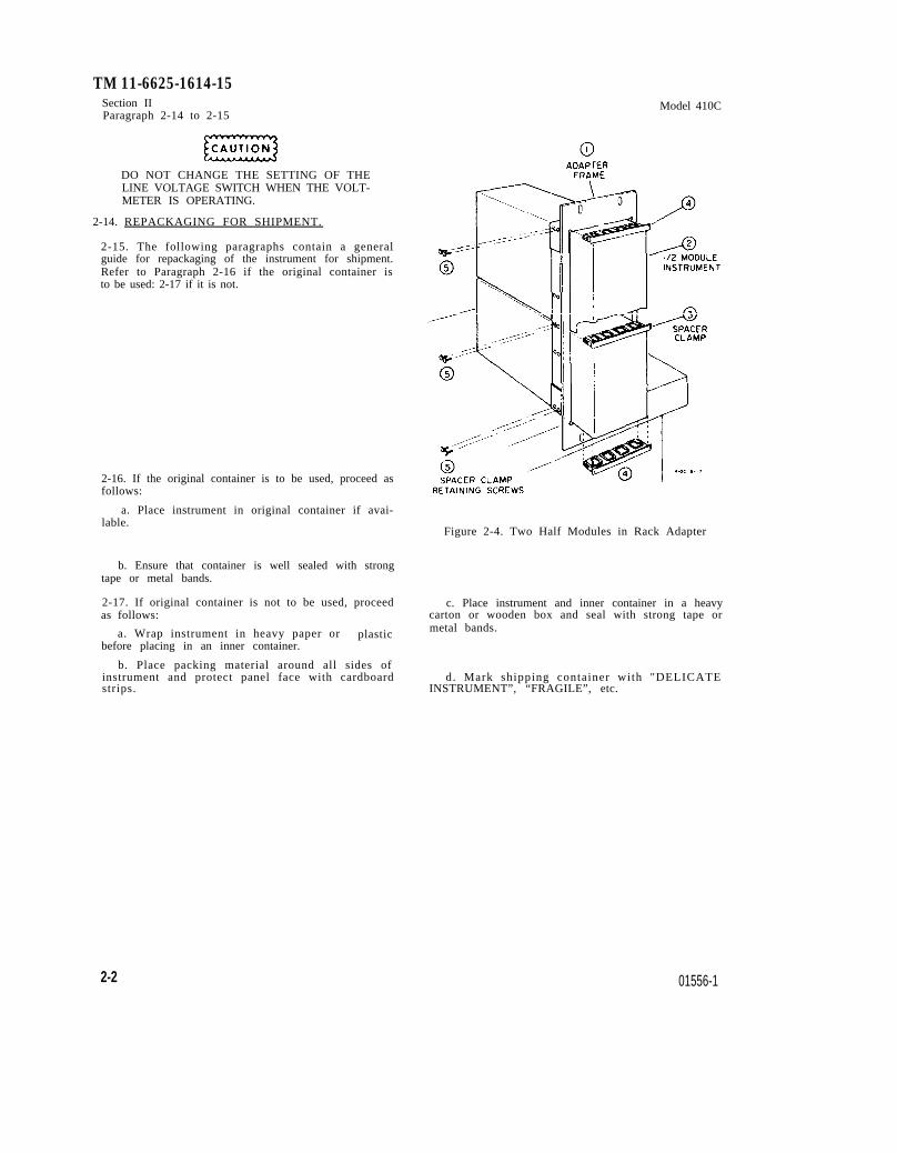
a. Place the adapter frame on edge of bench asshown in step 1, Figure 2-4.
b. Stack the submodular units in the frame asshown instep 2, Figure 2-4. Place the spacer clampsbetween instruments as shown in step 3, Figure 2-4.
c. Place spacer clamps on the two end instruments(see step 4, Figure 2-4) and push the combination intothe frame.
d. Insert screws on either side of frame, andtighten until submodular instruments are tight in theframe.
e. The compiete assembly is ready for rackmounting.
01556-2
2-9. THREE-CONDUCTOR POWER CABLE.
2-10. To protect operating personnel, the NationalElectrical Manufacturers’ Association (NEMA) re-commends that the instrument panel and cabinet begrounded. All Hewlett-Packard instruments areequipped with a three-conductor power cable whichgrounds the instrument when plugged into an appropri-ate receptacle.
2-11. To preserve the protection feature when oper-ating ihe instrument from a two-contact outlet, usethree - prong to two - prong adapter and connect thegreen pigtail on the adapter to ground.
2-12. PRIMARY POWER REQUIREMENTS.
2-13. The Modei 410C can be operated from either115 or 230 volts, 50 to 1000 cps. The instrument canbe easily converted from i 15- to 230- volt operation.The LINE VOLTAGE switch, S4 a two-position slideswitch located at the rear of the instrument, selectsthe mode of AC operation. The line voltage fromwhich the instrument is set to operate appears on thesiider of the switch. A 0.25-ampere, slo-blo fuse isused for both 115- and 230-volt operation.
Figure 2-3. Adapter Frame Instrument Combination
2-1
TM 11-6625-1614-15Section IIParagraph 2-14 to 2-15
DO NOT CHANGE THE SETTING OF THELINE VOLTAGE SWITCH WHEN THE VOLT-METER IS OPERATING.
2-14. REPACKAGING FOR SHIPMENT.
2-15. The following paragraphs contain a generalguide for repackaging of the instrument for shipment.Refer to Paragraph 2-16 if the original container isto be used: 2-17 if it is not.
2-16. If the original container is to be used, proceed asfollows:
a. Place instrument in original container if avai-
Model 410C
lable.Figure 2-4. Two Half Modules in Rack Adapter
b. Ensure that container is well sealed with strongtape or metal bands.
2-17. If original container is not to be used, proceed c. Place instrument and inner container in a heavyas follows: carton or wooden box and seal with strong tape or
a. Wrap instrument in heavy paper or metal bands.plasticbefore placing in an inner container.
b. Place packing material around all sides ofinstrument and protect panel face with cardboard d. Mark shipping container with "DELICATEstrips. INSTRUMENT”, “FRAGILE”, etc.
2-2 01556-1
TM 11-6625-1614-15Model 410C Section III
Paragraph 3-1 to 3-18
SECTION III
OPERATION
.
3-1. INTRODUCTION.
3-2. The Model 410C is used to measure AC and DCvoltage, DC current, and resistance. All measure-ment inputs are located on the front panel; a DC out-put connector is located on the rear panel. Frontpanel controls and indicators are color coded. DCvoltage, DC current and resistance knobs and indi-cators are in black; AC voltage controls and indica-tors are in red.
3-3. ADJUSTMENT OF MECHANICAL ZERO.
3-4. The procedure for adjustment of mechanicalzero is given in Section V.
3-5. FRONT AND REAR PANEL DESCRIPTION.
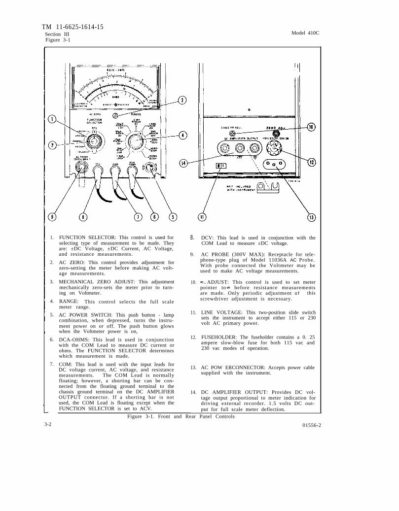
3-6. Figure 3-1 describes the function of all frontand rear panel controls, connectors and indicators .The description of each control, connector and indi-cator is keyed to a drawing which accompanies thefigure.
3-7. OPERATING PROCEDURES.
3-8. There are five operating procedures: DC Volt-age Measurements, Figure 3-2; DC Current Measure-ments, Figure 3-3; AC Voltage Measurements, Fig-ure 3-4; Resistance Measurements, Figure 3-7; andMeasuring DC Current in Nano-amperes, Figure 3-8.
3-9.
Note
Ageing of the neon tamps in the chopperassembly can cause a change in chopperfrequency which produces a slight osci-llatory movement of meter pointer. Ifthis oscillatory movement is observed,rotate Oac Freq Adj A3R5 (see Paragra-graph 5-28) in the ccw direction untiloscillation of pointer stops.
DC VOLTAGE MEASUREMENTS (Figure 3-2).
3-10. The Model 410C is normally floating; howevera shorting bar can be connected at the DC AMPLIFIEROUTPUT connector on the rear panel. When the instru-ment is floating, the COM Lead should not be connectedto voltages greater than 400 volts.
3-11. DC CURRENT MEASUREMENTS (Figure 3-3).
3-12. General instructions for the measurement ofDC current are the same as those given for DC volt-age measurements, Paragraph 3-9.
01556-2
3-13.
1
3-14.
AC VOLTAGE MEASUREMENT (Figure 3-4).
ONE SIDE OF ALMOST ALL POWERDISTRIBUTION SYSTEMS IS GROUNDED.EXTREME CAUTION MUST BE USED IFDIRECT MEASUREMENT OF POWERLINE VOLTAGES IS ATTEMPTED. IFTHE GROUND CLIP LEAD IS ACCIDEN-TALLY CONNECTED TO THE UN-GROUNDEDSIDE OF THE LINE. SEVEREDAMAGE TO THE 410C IS POSSIBLEBECAUSE OF THE SHORT CIRCUITCREATED. POWER LINE’ VOLTAGESCAN BE SAFELY MEASURED BY USINGTHE PROBE TIP ONLY. CONTACTINGTHE GROUNDED POWER CONDUCTORWILL GIVE A READING OF 0 VOLTSWHILE CONTACTING THE UN-GROUNDED LEAD WILL GIVE FULLVOLTAGE READING.
Although the Model 410C indicates a full scaleAC range of 500 volts, the optional Model 11036A ACProbe should not be connected to AC voltages in ex-cess of 300 volts RMS. AC voltage referenced to aDC voltage may be measured, but the AC Probe clip(alligator type) must be connected to the ground of the circuit under test.
WHEN MEASURING AC REFERENCEDTO DC, THE PEAK AC VOLTAGE PLUSDC VOLTAGE CONNECTED TO TREPROBE MUST NOT EXCEED 420 VOLTS.
3-15. PRECAUTION WHEN MEASURING AC VOLT-AGE.
3-16. Special considerations must be kept in mindwhen making AC voltage measurements. These con-siderations are discussed in the following paragraphs.
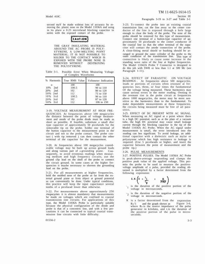
3-17. GENERAL CONSIDERATION OF COMPLEXWAVEFORMS. Waveforms containing appreciableharmonics or spurious voltages will introduce errorin the meter indication since the meter has been cali-brated to read RMS values of true sine waves whilethe Model 11036A Probe is a peak-above-averageresponding device.. The magnitude of error that maybe expected when harmonics are present on the mea-sured waveform is indicated in Table 3-1.
3-18. VOLTAGE MEASUREMENTS AT FREQUEN-CIES BELOW 50 CYCLES/SECOND. Voltage mea-surements at frequencies as low as 10 cycles per
3-1
TM 11-6625-1614-15Section III Model 410CFigure 3-1
1.
2.
3.
4.
5.
6.
7.
FUNCTION SELECTOR: This control is used forselecting type of measurement to be made. Theyare: ±DC Voltage, ±DC Current, AC Voltage,and resistance measurements.
AC ZERO: This control provides adjustment forzero-setting the meter before making AC volt-age measurements.
MECHANICAL ZERO ADJUST: This adjustmentmechanically zero-sets the meter prior to turn-ing on Voltmeter.
RANGE: This control selects the full scalemeter range.
AC POWER SWITCH: This push button - lampcombination, when depressed, turns the instru-ment power on or off. The push button glowswhen the Voltmeter power is on,
DCA-OHMS: This lead is used in conjunctionwith the COM Lead to measure DC current orohms. The FUNCTION SELECTOR determineswhich measurement is made.
COM: This lead is used with the input leads forDC voltage current, AC voltage, and resistancemeasurements. The COM Lead is normallyfloating; however, a shorting bar can be con-nected from the floating ground terminal to thechassis ground terminal on the DC AMPLIFIEROUTPUT connector. If a shorting bar is notused, the COM Lead is floating except when theFUNCTION SELECTOR is set to ACV.
8.
9.
10.
11.
12.
13.
14.
DCV: This lead is used in conjunction with theCOM Lead to measure ±DC voltage.
AC PROBE (300V MAX): Receptacle for tele-phone-type plug of Model 11036A AC Probe.With probe connected the Voltmeter may beused to make AC voltage measurements.
ADJUST: This control is used to set meterpointer to before resistance measurementsare made. Only periodic adjustment o f thisscrewdriver adjustment is necessary.
LINE VOLTAGE: This two-position slide switchsets the instrument to accept either 115 or 230volt AC primary power.
FUSEHOLDER: The fuseholder contains a 0. 25ampere slow-blow fuse for both 115 vac and230 vac modes of operation.
AC POW ERCONNECTOR: Accepts power cablesupplied with the instrument.
DC AMPLIFIER OUTPUT: Provides DC vol-tage output proportional to meter indication fordriving external recorder. 1.5 volts DC out-put for full scale meter deflection.
Figure 3-1. Front and Rear Panel Controls
3-2 01556-2
Model 410C
TM 11-6625-1614-15Section III
Paragraphs 3-19 to 3-27 and Table 3-1
second maY be made without loss of accuracy by re-moving the. plastic nose on the Model 11036A and usingin its place a 0.25 microfarad blocking capacitor inseries with the exposed contact of the probe.
THE GRAY INSULATING MATERIALAROUND THE AC PROBE IS POLY-STYRENE, A LOW-MELTING POINTMATERIAL. IT IS NOT POSSIBLE TOSOLDER TO THE CONTACT WHICH ISEXPOSED WITH THE PROBE NOSE ISREMOVED WITHOUT DESTROYINGTHE POLYSTYRENE.
Table 3-1. Possible Error When Measuring Voltageof Complex Waveforms
,% Harmonic
o10% 2nd20% 2nd50% 2ndl 0 % 3 r d20% 3rd50% 3rd
True RMS Value
100100.5102112100.5102112
Voltmeter Indication
10090 to 11080 to 12075 to 15090 to 11087 to 120106 to 150
3-19. VOLTAGE MEASUREMENT AT HIGH FRE-QUENCIES. At frequencies above 100 megacyclesthe distance between the point of voltage measure-ment and anode of the probe diode must be made asshort as possible. If feasible, substitute a small disctype capacitor of approximately 50 picofarsds for theremovable tip on the probe. Solder one terminal ofthe button capacitor to the measurement point in thecircuit and not to the probe contact. The probe con-tact ( with tip removed ) can then contact the otherterminal of the capacitor for the measurement.
3-20. At frequencies above 100 megacycles consid-erable voltage may be built up across ground leadsand along various part of a grounding piane. Con-sequently, to avoid erroneous readings when measur-ing medium and high frequency circuits, use theground clip lead on the shell of the probe to connectthe circuit ground. In some cases at the higher fre-quencies it maybe necessary to shorten the groundinglead on the probe.
3-21. For all measurements at higher frequencies,hold the molded nose of the probe as far from the ex-ternal ground piane or from object at ground potentialas can conveniently be done. Under typical conditions,this practice will keep the input capacitance severaltenths of a picofarad lower than otherwise.
3-22. For measurements above approximately 250megacycles it is almost mandatory that measurementsbe made on voltages which are confined to coaxialtransmission iine circuits. For applications of thistype, the Model 11036A Probe is particularly suitablebecause the physical configuration of the diode andprobe is that of a concentric line, and with a few pre-cautions it can be connected to typical coaxial trans-mission line circuits with little difficulty.
01556-2
3-23. TO connect the probe into an existing coaxialtransmission line, cut the line away so the center con-ductor of the line is exposed through a hole largeenough to clear the body of the probe. The nose of theprobe should be removed for this type of measurement.Connect one terminal of a button-type capacitor of ap-proximately 50 picofarads to the center conductor ofthe coaxial line so that the other terminal of the oapa-citor will contact the anode connection of the probe.A close-fitting metal shield or bushing should be ar-ranged to ground the outer cylinder of the probe to theouter conductor of the transmission line. This type ofconnection is likely to cause some increase in thestanding wave ratio of the line at higher frequencies.The Model 11042A Probe T Connector is designed todo this job with SWR or less than 1.1 at 500 Mc (seeParagraph 1-11).
3-24. EFFECT OF PARASITIC ON VOLTAGEREADINGS . At frequencies above 500 megacycles,leads or portions of circuits often resonate at fre-quencies two, three, or four times the fundamentalOf the voltage being measured. These harmonics maycause serious errors in the meter reading. Owning tothe resonant rise in the probe circuit at frequenciesabove 1000 megacycles, the meter may be more sen-sitive to the harmonics than to the fundamental. Tomake dependable measurements at these frequencies,the circuits being measured must be free of ail para-sitics.3-25. EFFECT OF DC PRESENT WITH AC SIGNAL.When measuring an AC signal at a point where thereis a high DC potential, such as at the plate of a vacuumtube, the high DC potential may cause small leakagecurrent through the blocking capacitor in the tip of theModel 11036A AC Probe. When the AC signal undermeasurement is small, the error introduced into thereading can bes significant. To avoid leakage, an addi-tional capacitor with a dielectric such as mylar orpolystyrene which has high resistance to leakage isrequired. (Use 5 picofarads or higher, and insert thecapacitor between the point of measurement and theprobe tip.)
3-26. PULSE MEASUREMENTS3-27. POSITIVE PULSES. The Model 11036A AC Probeis peak-above-average responding and clamps thepositive peak value of the applied voltage. This per-mits the probe to be used to measure the positive-voltage amplitude of a pulse, provided the reading ob-tained is multiplied by a factor determined from thefollowing expression:
t 1
t 2
K
is the duration of the positive portion of thevoltage in microseconds.
is the duration of the negative portion of thevoltage in microseconds.
is a factor determined from the expressionRo/t1 and the graph shown as Figure 3-6,where Ro is the source impedance of the pulsegenerator in kilohms, and t l is the duration ofthe positive portion of the pulse in micro-seconds.
3-3

TM 11-6625-1614-15Section IIIParagraphs 3-28 to 3-34
PRF is the pulse repetition frequency in pulses persecond (pps).
Suppose, for example:
t 1 =
t 2 =
K =
PRF =
10 microseconds
990 microseconds
0.55
1000 pps
To find K, assuming/
= 2 kilohms and tl=10micro-seconds: R o/
tl = 2 10° = 0.2. Location 0.2 on theX axis of the graph shown as Figure 3-6, and readingK where X and Y axes intersect the unmarked curve. Ifthe ratio of R o/
tl were greater than 1, multiply theX and Y axes by 10, and use the curve marked ”Ro/t1 and K each X10”.
Solving the expression for the multiplying factor,
Model 410C
3-28. NEGATIVE PULSES.
3-29. In the case of a 10 microsecond negative pulse(t2) and a pulse repetition frequency (PRF) of 1000 pps,tl would be 990 microseconds. Thus T o/
t1 would beapproximately 0, and from the graph it is seen thatK is approximately 0. The expression would thenreduce to
3-30. It can be seen that in the case of negative pulsesof short duration much smaller readings will be ob-tained for an equivalent positive pulse. As a result,large multiplying factors must be used and unless thepulse voltage is large, these measurements may beimpractical.
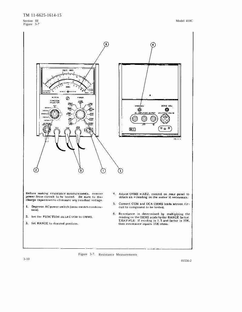
3-31. MEASURING RESISTANCE (Figure 3-7).
3-32. Before making resistance measurements, powermust be removed f rom the circuit to be tested. Also,make sure capacitors are discharged to eliminate anyresidual voltage.
3-33. MEASURING DC NANO-AMPERE CURRENT(Figure 3-8).
3-34. The Model 410C can be used to measure nano-ampere leakage current in transistors and diodes. Thethree most sensitive DC voltage measurement rangesare used to measure DC nano-ampere currents.
.
.
3-4

TM 11-6625-1614-15Model 410C Section III
F i g u r e 3 - 2
01556-2
Figure 3-2. DC Voltage Measurements
3-5

TM 11-6625-1614-15Section III Model 410CFigure 3-3
Figure 3-3. DC Current Measurements
3-601556-3

TM 11-6625-1614-15Model 410C Section III
Model 410C
Figure 3-4. AC Voltage Measurements
01556-3 3-7

Figure 3-5.
TM 11-6625-1614-15
Section III
Figure
3-5M
odel 410C
3-80
15
56
-2

TM 11-6625-1614-15Model 410C Section III
Figure 3-6
Figure 3-6. Graph Used in Calculation of Pulse Voltage Readings
01556-2 3-9
TM 11-6625-1614-15Section III Model 410CFigure 3-7
Figure 3-7. Resistance Measurements3-10 01556-2

TM 11-6625-1614-15Model 410C Section III
Figure 3-8
Figure 3-8. DC Nano-Amoere Current Measurements
01556-3 3-11

TM 11-6625-1614-15Section IVFigure 4-1 and 4-2
Model 410C
Figure 4-1. Block Diagram, Model 410C
F i g u r e 4 - 2 . M o d u l a t o r - D e m o d u l a t o r M e c h a n i c a l A n a l o g y
4-0 01556-2

TM 11-6625-1614-15Model 410C Section IV
Paragraph 4-1 to 4-18
4-1.
4-2.
OVERALL DESCRIPTION.
The Model 410C includes
SECTION IV
THEORY OF OPERATION
an input network, amodulator - amplifier- demodulator, and a metercircuit. A block diagram of the Model 410C is shownin Figure 4-1.
4-3. Signals to be measured are applied through theappropriate input lead to the input network. AC volt-ages are detected in the AC probe, and therefore allsignals to the input network are DC. The input net-work attenuates the DC signal to a level determinedby RANGE and FUNCTION SELECTOR settings. Theattenuated DC voltage is applied to the modulator whichconverts the DC to AC for amplification. The ampli-fied AC signal is converted back to DC voltage inthedemodulator and coupled to cathode follower VIB. Thecathode follower output to the DC AMPLIFIER OUT-PUT connector and meter circuit is a DC voltageproportional to the amplitude of the signal applied tothe input. A portion of the voltage to the meter circuitis returned to the modulator as feedback. When thefeedback voltage and attenuated DC voltage are nearlyequal, the meter stabilizes.
4-4. CIRCUIT DESCRIPTION.
4-5. INPUT NETWORK.
4-6. The input network includes a precision voltagedivider, which by means of the FUNCTION SELECTORand RANGE switches, providesa maximum of 15 milli-volts at the modulator input regardless of the rangeset and signal applied. The ± DCA, ±DCV, OHMS, andACV modes of operation are discussed below.
4-7. DC CURRENT MEASUREMENTS: Refer to Fig-ure 4-3, throughout this explanation. The purpose ofthe input network is to provide proper attenuation ofcurrents applied. Currents from 1.5 µa to 150 mafull scale are applied with input impedance decreasingfrom 9K ohms on the 1.5 µa range to approximately0.3 ohms on the 150 ma range.
4-6. Tbe change in input impedance is varied by usingDC current shunts in conjunction with RANGE switchA2S2. The DC voltage developed across these shuntresistors, when applied through the modulator-am-plifier-demodulator network to the meter, provide adeflection on the meter proportional to the DC currentbeing measured.
4-9. DC VOLTAGE MEASUREMENTS. Refer toFigure 4-4 throughout this explanation. The purposeof the input network is to accurately attenuate the in-put signal to a maximum of 15 millivolts at the modu-
01556-2
later input. The network presents an input impedanceof 10 megohms on the three most sensitive ranges and100 megohms on all other ranges.
4-10. The resistor R1 (located in the DCV probe) inconjunction with resistors A2R10 through A2R26, pro-vides the 10 megohm input impedance required for thethree most sensitive DCV ranges. Resistors A2R4and A3R30 are shunted out of the circuit by the RANGEswitch on the three most sensitive DCV ranges.
4-11. When using the eight less sensitive ranges,A2R4 and A3R30 are placed in series with Rl andA2R10 through A2R26 to present more than 100 meg-ohm impedance to the input.
4-12. A3R30 is used to calibrate full scale on the1500 volt range. (See Paragraph 5-35. )
4-13. RESISTANCE MEASUREMENTS. The purposeof the input network shown in Figure 4-5 is to placeapproximately 0. 6 volt DC source in series with aknown (reference) resistance. The resistance to bemeasured is ptaced in parallel with the known resis-tance, which changes the voltage proportionally. Themaximum changes in voltage applied to the modulatoris 15 mv because of attenuation provided by A2R4,A3R30, and A1R2.
4-14. A DC current of approximately 60 ma issupplied at the junction of A2R22 and A2R23 throughA7R10, R2, A2R2 and A2R1 to the input network. TheOHMS ADJ., R3, sets the meter for full scaleResistor A2R1 is shorted out in the XIM position ofthe RANGE switch; resistors A2R1 and A2R2 areshorted out in the X10M range. The resistors A2R2and/or A2R1 are electrically removed from the cir-cuit to increase the voltage at the junction of A2R22and A2R23. This is done to compensate for tbe load-ing of the attenuator (A2R4, A3R30, and A1R2) onthese ranges.
4-15. AC VOLTAGE MEASUREMENTS. Refer toFigure 4-6 throughout this explanation. Voltage atthe AC probe is converted to DC and applied to the in-put network. The input signal is attenuated to producea maximum of about 15 millivolts at the modulator in-put . AC zero adjustment of meter pointer is madewith the AC ‘ZERO control.
4-16. MODULATOR-DEMODULATOR.
4-17. Refer to the Amplifier Schematic, Figure 5-10 ,and to the Mechanical Analogy Schematic, Figure4-2 throughout this explanation.
4-18. The input network applies approximately 15millivolts DC, for full scale meter deflection (posi-tive or negative, depending on the polarity of the
4-1

TM 11-6625-1614-15Section IVParagraphs 4-19 to 4-31
Model 410C
voltage or current being measured) to the neon-photo-conductor chopper. Also applied to the opposite sideof the chopper is the amplifier feedback voltage, whichis of the same polarity and approximately 5 micro-volts lower in amplitude than the input voltage. Themodulator-chopper consists of two photoconductors,A4V1 and A4V2, which are alternately illuminated bytwo neon lamps, A4DS1 and A4DS2, respectively. Theneon lamps are part of a relaxation oscillator, whosefrequency is controlled by A3R5. The oscillator fre-quency is nominally set to 100 cps for operation from60 cps power line, or to 85 cps for 50 cps line. Thisfrequency is selected so that it is not harmonicallyrelated to the power line frequency, precluding pos-sible beat indications on the meter.
4-19. As the photoconductors are alternately illumi-nated by the neona, their respective resistances arelow (conductive ) when illuminated and high (non-con-ductive) when darkened. Therefore the input voltageand feedback voltage are alternately applied to theinput amplifier. The amplitude of the resultant signalto the amplifier is the voltage difference between theinput and feedback voltages.
4-20. The chopped DC signal is amplified by a threestage RC amplifier, consisting of A3V1A, A3Q1 andA3Q2. The amplified signal to the input of the de-modulator-chopper is 180° out of phase with the out-put of the modulator-chopper.
4-21. The demodulator - chopper consists of twophotoconductors, A4V3 and A4V4, which are alternatelyilluminated by neon tamps A4DS1 and A4DS2, respecti-vely. Approximately 150 millivolts square-wave isapplied to the demodulator from the amplifier. Sincethe same neon lamps illuminate both the modulatorand demodulator photoconductors, operation of the twochopper is synchronous. Therefore, when A4V1 issampling the input voltage, A4V3 is clamping theamplified and inverted difference voltage to ground.Alternately, when A4V2 is sampling the feedback vol-tage, A4V4 is charging capacitors A3C13 and A3C14to the peak value of the square-wave. These capaci-tors maintain this charge so long as the input voltageremains constant by virtue of having no dischargepath and because they are being repetitively rechargedby the demodulator.
4-22. Therefore, a DC potential, proportional to thedifference between the input and feedback voltages, isapplied to the grid of the cathode follower and subse-quently to meter circuit and DC AMPLIFIER OUTPUTconnector. A portion of the meter circuit voltage isfed back to the modulator. The meter stabilizes whenthe feedback voltage and input voltages are nearlyequal.
4-23. THE FEEDBACK NETWORK.
4-24. The feedback network drives the meter anddetermines the DC gain of the amplifier. The feed-back is varied depending on the position of the FUNC-TION and RANGE selectors. The different feedbackconfigurations are discussed below.
4-25. FEEDBACK NETWORK FOR ±DCA. OHMS,AND ±DCV. Figures 4-3, 4-4 and 4-5 show the feed-back configuration for ail positions of the FUNCTIONSELECTOR except ACV. The meter is electricallyinverted for ±DCV and ±DCA modes of operation. TheDC OUTPUT ADJ., A6R20 sets the output voltage. TheDC pot, A6R18 determines the amount of feedback tothe modulator. The resistor A2R30 is in the circuitin the ± .015 DCV and ±1.5 µa modes of operation, todecrease feedback and thus increase amplifier gain tocompensate for the decrease in input signal to themodulator on these ranges.
4-26. FEEDBACK CIRCUIT FORAC VOLTAGE MEA-SUREMENTS: Figure 4-6 shows the feedback confi-guration for the ACV position of the FUNCTION SEL-ECTOR switch, A2S2. The resistors that are placedin the circuit by the RANGE switch program the am-plifier gain to compensate for the non-linear responseof the AC probe. A6R16 and A6CR1 compensate thenon-linear response of the AC probe to the linearcalibration of the upper meter scale on the 5 voltrange.
4-27. POWER SUPPLY.
4-28. PRIMARY POWER. Either 115 or 230 volt acpower is connected through fuse R1 (0.25 amp slo-blo)and switch S3 to the primary of power transformerT1. Switch S4 connects T1 primaries in parallel forl15 volt operation of in series for 230 voit operation.
4-29. UNREGULATED AND ZENER REGULATEDPOWER SUPPLY. Full wave rectifier CR1 and CR2produces unregulated +270 volts, which is used todrive the photochopper neons. Unregulated +175 voltsand +140 volts are tapped off and are used to provideB+ to the plates of A4V1B and A4V1A, respectively.Zener regulators A7CR6 and CR7 provide regulated+38 volts and -9 volts to bias A3Ql and A3Q2. Filteringof the outputs is provided by the RC network consistingof A7R1 through A7R3 and C5A through C5D.
4-30. SERIES REGULATED POWER SUPPLY. Theoutput of the full wave rectifier CR3 and CR4 is re-gulatedbytransistor Ql, which is connected in serieswith the output. Zener diode A7CR8 provides referencevoltage to the base of Q1. Regulated +6 volts is suppliedto the filaments of A3VlA/B and the AC Probe diodeA6V1. +0.6 volts is provided through A7R10 to R3,the OHMS ADJ, control. Filtering of the outputs isprovided by C6A and C6B.
4-31. STANDBY FILAMENT SUPPLY. The filamenttap (Tl, Pins 1 and 2) provides 6.0 volts actothefilament of the AC probe diode, A8V1, so that thefilament remains warm when the Modei 410C is beingused in modes of operation other than ACV. W h e nFUNCTION selector A1S1 is switched to ACV, 6.0volts AC is removed from the filament and 6 volts DCis applied. Therefore, the ACV mode is ready forimrnediate use, without waiting for the filament towarm up.
4-2 01556-2

Figure 4-3.
Model 410C
TM
11-6625-1614-15S
ection IV
Figure
4-3
01556-24-3

Figure 4-4.
TM
11-6625-1614-15S
ection IV
Figure
4-4M
odel 410C
4-401556-2

Figure 4-5.
TM
11-6625-1614-15S
ection IV
Figure
4-5
01556-24-5
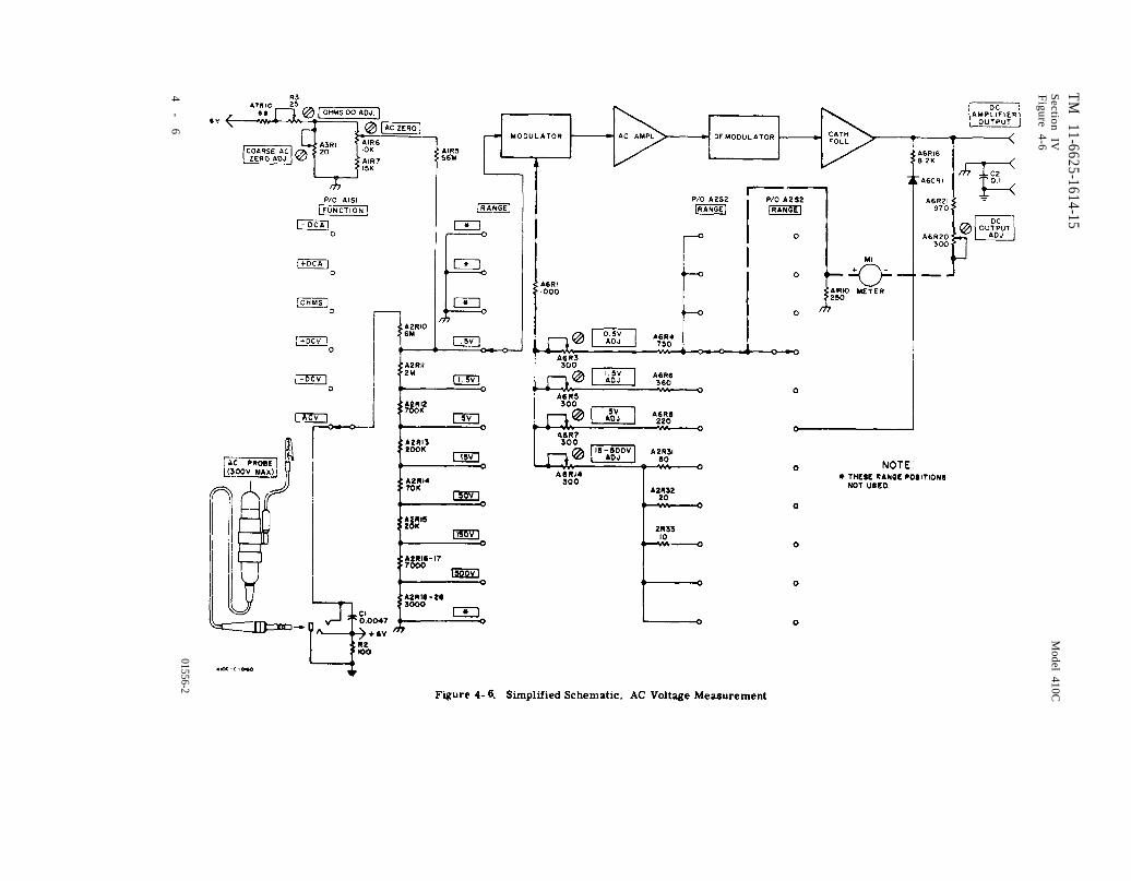
Figure 4-6.
TM 11-6625-1614-15
Section
IVF
igure 4-6
Model 410C
4-
601556-2


TM 11-6625-1614-15Section V Model 410CTable 5-1
Table 5-1. Recommended Test Equipment
Instrument Type Required Characteristics Use Recommended Model
Voltmeter Calibrator Range: .015 to 300 v AC and DC Accuracy @ Model 738BR Volt-Frequency: DC and 400 cps Checks and Calibration meter CalibratorAccuracy: +0. 370 AC Adjustments
*O. 2%0 DC
DC Power Supp Iy Range: O to 10 v continuous DC Ammeter Accuracy @Model 723A DC Power IChecks supply
DC Voltmeter Range: 10 v Accumcy Checks; Power @ Model 3440A/3442A i
Accuracy: +0. 2% Supply Measurements; Digital VoltmeterTroubleshooting
Frequency Response Frequency: 20 cps to 10 Mc Frequency Response Test @ Model 739AR Freq-Test Set with external oscillator uency Response Test
Output: 2 v into 50 ohms Set
Oscillator Frequency: 20 cps to 10 Mc Frequency Response Test @ Model 651A Testoutput : 2.0 v Oscillator
RF Signal Generator Frequency: 10 Mc to 480 Mc Frequency Response Test @ Model 608C RFSigmaloutput: 1.0 v Generator
Power Meter Frequency: 10Mc to700 Mc Frequency Response Test @ Model 431B PowerRange: 1.0 v Meter
VHF Signal Generator Frequency: 480 Mc to 700Mc Frequency Response Test @ Model 612A VHFSignal Generator
AC Voltmeter Range: 115 V Power Supply Measure- @ Model 3400A RMSments (ripple) Voltmeter
Electronic Counter Frequency Range: to at Chopper Frequency Adjust @ Model 521C Electronicleast 102 cps Counter
DC Standard output: 1000 v DC Adjust @ Model 740A DCAccuracy: +0. 2% Standard
Ohmmeter Range: 100 Mf2 Troubleshooting @ Model 412A DC VTVMAccuracy: +5%
Thermistor Mount Frequency: 10 Mc to 700Mc Frequency Response Test @? Model 478A CoaxialImpedance: 50 ohm match Thermistor Mount
Pr~be-T-Connector For use with 50 ohm trans- Frequency Response Test @ Model 11042A Probe-mission line T-Connector
10 KC Filter High pass fi 1 ter capable of Frequency Response Test @ Model K02-411A10 kc re]ection 10 KC Filter
Connector Adapter Male BNC to male BNC Frequency Response Test @ Part No. 1250-0216
Connector Adapter Type N male to BNC female Frequency Response Test @ Part No. 1250-0067
Resistors:
10 M!l Accuracy: *1% Performance Checks & Part No. 0730-01685 MQ Accuracy: +1% Performance Checks4,5Mfl Accuracy: +1%
@ Part No. 0730-0125Performance Checks @ Part No. 0730 -015’7
500 K Accuracy: +1% Performance Checks @ Part No. 0721-001156 K Accuracy: *1% Performance Checks @ Part No. 0730-005310 K Accuracy: +1% Performance Checks9K
@ Part No. 0727-0157Accuracy: *I?o Performance Checks
1.5K@ Part No. 0730-0026
Accuracy: *1% Performance Checks @ Part No. 0730 -001’7
56 ohms Accuracy: +1% Performance Checks10 ohms
@ Part No. 0811-0341Accuracy: *170 Performance Checks @ Part No. 0727-0335
.
5-0 01556-2
TM 11-6625-1614-15Model 410C Section V
Paragraphs 5-1 to 5-11
5 - 1 . I N T R O D U C T I O N .
SECTION VMAINTENANCE
5-2. This section contains maintenance proceduresfor the Model 410C Electronic Voltmeter.
5-3. TEST EQUIPMENT REQUIRED.
5-4. The test equipment required to maintain andadjust the Model 410C is listed in Table 5-1. Equi-pment having similar characteristics may be substi-tuted for items listed.
5-5. PERFORMANCE CHECKS.
5-6. The performance checks presented in thissection are front panel operations designed to com-pare the Model 410C with it’s published specifications.These operations may be incorporated in periodicmaintenance, post repair and incoming quality controlchecks. These operations should be conducted beforeany attempt is made at instrument calibration oradjustment. During performance checks, periodicallyvary the line voltage to the Model 410C, ± 10% on either115v or 230 v operation. A 1/2 hour warm-up periodshould be allowed before these tests are conducted.
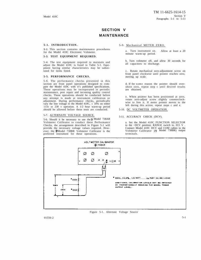
5-7. ALTERNATE VOLTAGE SOURCE.
5-6. Should it be necessary to use theVoltmeter Calibrator to conduct these PerformanceChecks, the arrangement described in Figure 5-1 willprovide the necessary voltage values required. How-ever; the Model 738BR Voltmeter Calibrator is the
5 -9 . Mechan ica l METER ZERO.
a. Turn instrument on. Allow at least a 20minute warm-up period.
b. Turn voltmeter off, and allow 30 seconds forall capacitors to discharge.
c. Rotate mechanical zero-adjustment screw onfront panel clockwise until pointer reaches zero,moving up scale.
d. If for some reason the pointer should over-shoot zero, repeat step c until desired resultsare obtained.
e. When pointer has been positioned at zero,rotate zero-adjust screw slightly counterclock-wise to free it. If meter pointer moves to theleft during this action, repeat steps c and e.
5-10. DC VOLTMETER OPERATION.
5-11. ACCURACY CHECK (DCV).Model 738AR
a. Set the Model 410C FUNCTION SELECTORto the +DCV position; RANGE switch to. 015 V .Connect Model 410C DCV and COM cables to theVoltmeter Calibrator Model 738BR) output
preferred instrument for these operations. terminals.
Figure 5-1. Alternate Voltage Source
01556-2 5-1
TM 11-6625-1614-15Section VParagraphs 5-12 to 5-15Table 5-2
Model 410C
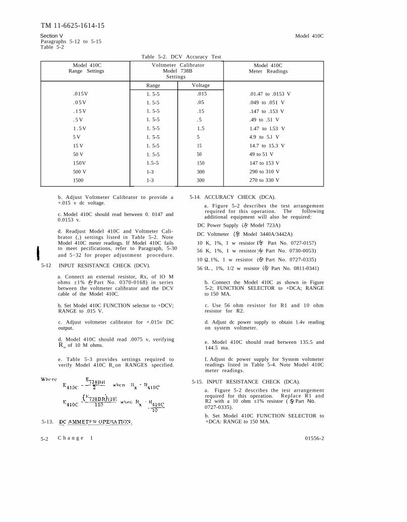
Table 5-2. DCV Accuracy Test
Model 410CRange Settings
.015V
. 0 5 V
. 1 5 V
. 5 V
1 . 5 V
5 V
15 V
50 V
150V
500 V
1500
5-12
Voltmeter CalibratorModel 738B
Settings
Range
1. 5-5
1. 5-5
1. 5-5
1. 5-5
1. 5-5
1. 5-5
1. 5-5
1. 5-5
1.5-5
1-3
1-3
b. Adjust Voltmeter Calibrator to provide a+.015 v dc voltage.
c. Model 410C should read between 0. 0147 and0.0153 v.
d. Readjust Model 410C and Voltmeter Cali-brator (,) settings listed in Table 5-2. NoteModel 410C meter readings. If Model 410C failsto meet pecifications, refer to Paragraph, 5-30and 5−32 for proper adjustment procedure.
INPUT RESISTANCE CHECK (DCV).
a. Connect an external resistor, Rx, of lO Mohms ±1% ( Part No. 0370-0168) in seriesbetween the voltmeter calibrator and the DCVcable of the Model 410C.
b. Set Model 410C FUNCTION selector to +DCV;RANGE to .015 V.
c. Adjust voltmeter calibrator for +.015v DCoutput.
d. Model 410C should read .0075 v, verifyingR in of 10 M ohms.
e. Table 5-3 provides settings required toverify Model 410C R in on RANGES specified.
5-13.
5-2
Voltage
.015
.05
.15
. 5
1.5
5
15
50
150
300
300
Model 410CMeter Readings
.01.47 to .0153 V
.049 to .051 V
.147 to .153 V
.49 to .51 V
1.47 to l.53 V
4.9 to 5.l V
14.7 to 15.3 V
49 to 51 V
147 to 153 V
290 to 310 V
270 to 330 V
5-14. ACCURACY CHECK (DCA).
a. Figure 5-2 describes the test arrangementrequired for this operation. The followingadditional equipment will also be required:
DC Power Supply Model 723A)
DC Voltmeter Model 3440A/3442A)
10 K, 1%, 1 w resistor Part No. 0727-0157)
56 K, 1%, 1 w resistor Part No. 0730-0053)
10 , 1%, 1 w resistor Part No. 0727-0335)
56 , 1%, 1/2 w resistor Part No. 0811-0341)
b. Connect the Model 410C as shown in Figure5-2; FUNCTION SELECTOR to +DCA; RANGEto 150 MA.
c. Use 56 ohm resistor for R1 and 10 ohmresistor for R2.
d. Adjust dc power supply to obtain 1.4v readingon system voltmeter.
e. Model 410C should read between 135.5 and144.5 ma.
f. Adjust dc power supply for System voltmeterreadings listed in Table 5-4. Note Model 410Cmeter readings.
5-15. INPUT RESISTANCE CHECK (DCA).
a. Figure 5-2 describes the test arrangementrequired for this operation. Replace R1 andR2 with a 10 ohm ±1% resistor Part No.0727-0335).
b. Set Model 410C FUNCTION SELECTOR to+DCA: RANGE to 150 MA.
C h a n g e 1 01556-2

TM 11-6625-1614-15Model 410C Section V
Tables 5-3 and 5-4Figure 5-2
Figure 5-2. DC Ammeter Operation
Table 5-3. DCV Input Resistance Test
Table 5-4. DCA Accuracy Test
01556-2 5-3

TM 11-6625-1614-15Section VParagraphs 5-16 to 5-19Table 5-5
Model 410C
g .
5-16.
c. Adjust dc power supply to provide systemvoltmeter reading of 1.50 v.
e. Model 410C should read approximately150 ma. This will verify a R in o f a p p r o x i -mately 0.3 ohms, where
R410C = Etotal - RX
I4 1 0 C
I410C
f. Set Model 410C RANGE to 1.5 µa.
Replace Rx with a 9 K ohm ±1% resistor Part No. 0730-0026).
h. Adjust dc power supply to provide systemvoltmeter reading of 13.5 mv.
j. Model 410C should read approximately 1.5µa. This will verify R in of 9 K on 1.5 µarange.
OHMMETER OPERATION.
a. A 10 ohm ±l% resistor Part No. 0727-0335) and a 10M resistor Part No. 0730-0168) will be required for this test.
b. Set Model 410C FUNCTION SELECTOR toOHMS; RANGE to RX10.
c. Set pointer to using rear panel adjust-ment (OHMS ADJ) if required.
h. If both of these ranges function properly, itcan be assumed that the remainder will also .If meter does not function properly, refer toParagraph 5-31 for adjustment procedure.
5-17. AMPLIFIER OPERATION.
D e l e t e dsee paras 5-19 and 5-24
d. Connect COM and DCA OHMS cables across10 ohm resistor.
5-19. AMPLIFIER GAIN CHECK.
e. Meter should read 1 (±5%), indicating 10ohms.
f. Reset Model 410C RANGE to RX10M. Re-place 10 ohm resistor with 10 M ohm resistor.
g. Meter should read 1 (+5%), indicating 10 Mohms.
Table 5-5. DC Voltage
a. Connect Voltmeter C a l i b r a t o r M o d e l738BR) output to Model 410C DCV and COMcables.
b. Connect DC Voltmeter Model 3440A/3442A) to DC AMPLIFIER OUTPUT on rearpanel of Model 410C. Set DC Voltmeter RANGEto 10 v.
Output Test
D e l e t e d
5-4 C h a n g e 1 01556-2
TM 11-6625-1614-15
.
Model 410C Section VParsgraphs 5-20 to 5-23
Figure 5-3
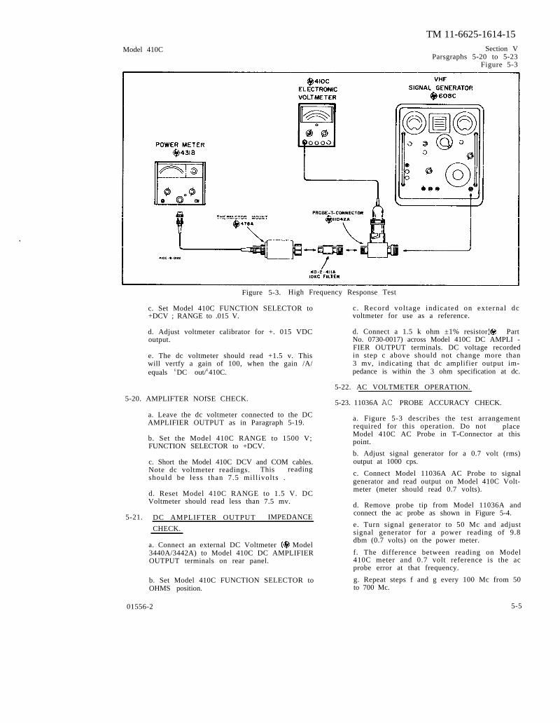
Figure 5-3. High Frequency Response Test
c. Set Model 410C FUNCTION SELECTOR to+DCV ; RANGE to .015 V.
d. Adjust voltmeter calibrator for +. 015 VDCoutput.
e. The dc voltmeter should read +1.5 v. Thiswill vertfy a gain of 100, when the gain /A/equals EDC out/E410C.
5-20. AMPLIFTER NOfSE CHECK.
a. Leave the dc voltmeter connected to the DCAMPLIFIER OUTPUT as in Paragraph 5-19.
b. Set the Model 410C RANGE to 1500 V;FUNCTION SELECTOR to +DCV.
c. Short the Model 410C DCV and COM cables.Note dc voltmeter readings. This readingshould be less than 7.5 mill ivolts .
d. Reset Model 410C RANGE to 1.5 V. DCVoltmeter should read less than 7.5 mv.
5-21. DC AMPLIFTER OUTPUT IMPEDANCE
CHECK.
a. Connect an external DC Voltmeter Model3440A/3442A) to Model 410C DC AMPLIFIEROUTPUT terminals on rear panel.
b. Set Model 410C FUNCTION SELECTOR toOHMS position.
c. Record voltage indicated on external dcvoltmeter for use as a reference.
d. Connect a 1.5 k ohm ±1% resistor PartNo. 0730-0017) across Model 410C DC AMPLI -FIER OUTPUT terminals. DC voltage recordedin step c above should not change more than3 mv, indicating that dc amplifier output im-pedance is within the 3 ohm specification at dc.
5-22. AC VOLTMETER OPERATION.
5-23. 11036A AC PROBE ACCURACY CHECK.
a. Figure 5-3 describes the test arrangementrequired for this operation. Do not placeModel 410C AC Probe in T-Connector at thispoint.
b. Adjust signal generator for a 0.7 volt (rms)output at 1000 cps.
c. Connect Model 11036A AC Probe to signalgenerator and read output on Model 410C Volt-meter (meter should read 0.7 volts).
d. Remove probe tip from Model 11036A andconnect the ac probe as shown in Figure 5-4.
e. Turn signal generator to 50 Mc and adjustsignal generator for a power reading of 9.8dbm (0.7 volts) on the power meter.
f. The difference between reading on Model410C meter and 0.7 volt reference is the acprobe error at that frequency.
g. Repeat steps f and g every 100 Mc from 50to 700 Mc.
01556-2 5-5

TM 11-6625-1614-15Section V Model 410CParsgraphs 5-24 to 5-25Figure 5-4, Table 5-6
Figure 5-4. Low Frequency Response Test
AC VOLTMETER ACCURACY CHECK.
a. A Voltmeter Calibrator Model 738BR)will be required for this operation.
b. Adjust voltmeter calibrator for 400 cps-rms output.
c. Set Model 410C FUNCTION SELECTOR toACV; RANGE to 500 V.
d. Adjust the voltmeter calibrator to settingslisted in Table 5-6. Model 410C should indicatereadings within limits specified. If not, refer
5-25. AC VOLTMETER FREQUENCY RESPONSECHECK.
a. A Frequency Response Test Set Model739AR), a Test Oscillator Model 651A), anRF Signal Generator Model 608 C), a PowerMeter Model 431 B), a Thermistor Mount Model 478A), a Probe - T - Connector Model 11042A), a VHF Signal Generator Model 612A) and a 10 KC Filter Model K02-411A) will be required for this operation. Fig-ure 5-3 and 5-4 describe the arrangement to be
Table 5-6. AC Accuracy Test
5-6 C h a n g e 1 01556-2
Model 410C TM 11-6625-1614-15
b . C o n n e c t t h e M o d e l 4 1 0 C a s s h o w n i n F i g u r e 5 - 4 . S e t M o d e l
410C FUNCTION SELECTOR toACV; RANGE to 1.5 V.
c . S e t f r e q u e n c y r e s p o n s e t e s t s e t t o E X T E R N A L .
d . A d j u s t t e s t o s c i l l a t o r o u t p u t A M P L I T U D E t o p r o v i d e M o d e l
410C reading of 1.4 V; FREQUENCY to 400 cps.
e . S e t f r e q u e n c y r e s p o n s e t e s t s e t M E T E R S E T t o c o n v e n i e n t
SET LEVEL.
f . V a r y t e s t o s c i l l a t o r f r e q u e n c y f r o m 2 0 c p s t o 1 0 M c . M o d e l
4 1 0 C s h o u l d r e a d b e t w e e n 1 . 2 5 a n d 1 . 5 5 v a t a l l f r e q u e n c i e s .
W h e n c h e c k i n g t h e f r e q u e n c y r e s p o n s e f r o m 2 0 c p s t o 5 0 c p s ,
d i s c o n n e c t t h e 1 1 0 4 2 A f r o m t h e t e s t s e t u p i n f i g u r e 5 - 4 . R e p l a c e
t h e p r o b e t i p o n t h e M o d e l 1 1 0 3 6 A a n d c o n n e c t d i r e c t l y t h r o u g h a
5 0 - o h m l o a d t o t h e o u t p u t o f t h e F r e q u e n c y R e s p o n s e T e s t S e t .
C o n n e c t t h e o u t p u t o f t h e T e s t O s c i l l a t o r d i r e c t l y t o t h e i n p u t
o f t h e F r e q u e n c y R e s p o n s e T e s t S e t . O b s e r v e s t e p g t h r o u g h o u t
t h e e n t i r e o p e r a t i o n .
g . I f f r e q u e n c y r e s p o n s e t e s t s e t d e f l e c t i o n v a r i e s f r o m p r e s e t
S E T L E V E L , a d j u s t t e s t o s c i l l a t o r o u t p u t a m p l i t u d e t o r e t u r n
p o i n t e r t o o r i g i n a l p o s i t i o n .
h . T o c h e c k M o d e l 4 1 0 C f r e q u e n c y r e s p o n s e f r o m 1 0 M c t o 4 8 0 M c ,
u s e a r r a n g e m e n t d e s c r i b e d i n F i g u r e 5 - 3 .
i . Set Model 410C FUNCTION SELECTOR to ACV; RANGE to .5 V.
j . A d j u s t R F s i g n a l g e n e r a t o r t o p r o v i d e M o d e l 4 1 0 C r e a d i n g
o f 0 . 4 5 V a t 1 0 M c . N o t e p o w e r m e t e r r e a d i n g ; m a r k f o r f u t u r e
r e f e r e n c e .
5 - 7

TM 11-6625-1614-15 Model 410C
k . V a r y R F s i g n a l g e n e r a t o r f r e q u e n c y f r o m 1 0 M c t o 4 8 0 M c .
M o d e l 4 1 0 C s h o u l d r e a d b e t w e e n 0 . 4 0 t o 0 . 5 0 v a t a l l f r e q u e n c i e s .
l . I f p o w e r m e t e r p o i n t e r v a r i e s f r o m r e f e r e n c e d e t e r m i n e d i n
s t e p j a b o v e , r e a d j u s t R F s i g n a l g e n e r a t o r O U T P U T L E V E L t o r e t u r n
p o i n t e r t o r e f e r e n c e d e f l e c t i o n .
m . T o c h e c k M o d e l 4 1 0 C f r e q u e n c y r e s p o n s e f r o m 4 8 0 M c t o 7 0 0
M c , r e p l a c e R F s i g n a l g e n e r a t o r w i t h V H F S i g n a l G e n e r a t o r ( H - P
M o d e l 6 1 2 A ) a n d r e p e a t s t e p s i t h r o u g h m a b o v e . M o d e l 4 1 0 C
s h o u l d n o t v a r y m o r e t h a n ± 1 0 % f r o m r e f e r e n c e .
5-26. ADJUSTMENT AND CALIBRATION PROCEDURE.
5 - 2 7 . T h e f o l l o w i n g i s a c o m p l e t e a d j u s t m e n t a n d c a l i b r a t i o n
p r o c e d u r E f o r t h e M o d e l 4 1 0 C . T h e s e o p e r a t i o n s s h o u l d b e c o n d u c t e d
o n l y i f i t h a s p r e v i o u s l y b e e n e s t a b l i s h e d b y P e r f o r m a n c e C h e c k s ,
P a r a g r a p h 5 - 5 , t h a t t h e M o d e l 4 1 0 C i s o u t o f a d j u s t m e n t .
I n d i s c r i m i n a t e a d j u s t m e n t o f t h e i n t e r n a l c o n t r o l s t o “ r e f i n e ”
s e t t i n g s m a y a c t u a l l y c a u s e m o r e d i f f i c u l t y . I f t h e p r o c e d u r e s
o u t l i n e d d o n o t r e c t i f y a n y d i s c r e p a n c y t h a t m a y e x i s t , a n d a l l
c o n n e c t i o n s a n d s e t t i n g s h a v e b e e n r e c h e c k e d , r e f e r t o P a r a g r a p h
5 - 3 6 , T r o u b l e s h o o t i n g , f o r p o s s i b l e c a u s e a n d r e c o m m e n d e d c o r r e c t i v e
a c t i o n .
5-28. CHOPPER FREQUENCY ADJUST.
a . A V o l t m e t e r C a l i b r a t o r ( H - P M o d e l 7 3 8 B R ) a n d a n E l e c t r o n i c
C o u n t e r ( H - P M o d e l 5 2 l C ) a n d a n A C V o l t m e t e r ( H - P M o d e l 3 4 0 0 A )
w i l l b e r e q u i r e d .
5 - 8

TM 11-6625-1614-15
b. U s e a c v o l t m e t e r t o v e r i f y M o d e l 4 1 0 C l i n e f. Observe counter, and adjust A3R5 for a chop-
voltage of 115 v. Chopper frequency wil l vary with per frequency of 100 cps ( ±2 cps) .
l ine voltage variat ions.
c . C o n n e c t 4 1 0 C , e l e c t r o n i c c o u n t e r , a n d5 - 2 9 . P o w e r S u p p l y A d j u s t m e n t
voltmeter as ahown in Figure 5-6.1. a. R e f e r t o T a b l e 5 - 7 f o r P o w e r S u p p l y c h e c k
d. Set M o d e l 4 1 0 C F U N C T I O N S E L E C T O R t op o i n t s a n d t y p i c a l v o l t a g e v a l u e s . M e a s u r e d c
+ D C V ; R A N G E t o 1 . 5 V .v o l t a g e s b e t w e e n c o m m o n a n d d e s i g n a t e d l o c a t i o n
o n A l .e. Adjust voltmeter cal ibrator to supply + 5 V dc b. S e t M o d e l 4 1 0 C F U N C T I O N t o A C V . S h o r t
to the Model 410C (DCV and COM cables) . A C V a n d C O M c a b l e .
Table 5-7, Power Supply Test
voltage Location on A7 Tolerance
+ 175 v Wht/blk and Orange ± 3 0 V+ 3 8 V Junction of CR6 and R4 ±8.0 V+ 6 V Cathode of CR8 ±0.6 V
–9.1 V Anode of CR7 + 1 . 8 V
c. Measure + 175 volt ac r ipple with ac voltmeter
(H-P Model 3400A). RMS value of r ipple should not
exceed 2.5 mv.
5 - 3 0 . D C Z e r o A d j u s t m e n t a n d B i a s
a. Se t Mode l 410C Func t ion Se l ec to r t o + DCV
and Range Switch to .5 V.
b. S h o r t D C V C a b l e t o C O M C a b l e .
c . A d j u s t A 3 R 2 1 f u l l y c o u n t e r c l o c k w i s e , a n d
then rotate about 20° clockwise.
d. Adjus t ZERO ADJ po t on r ea r pane l f o r z e ro
meter deflect ion. Switch to – DCV. If any deflect ion
i s o b s e r v e d , a d j u s t Z E R O A D J p o t t o r e t u r n m e t e r
pointer halfway back to zero. Check zero set t ing on
all ranges for both + DCV and – DCV. Zero offset
should not exceed 1070 in any case.
5 - 3 1 . D C A m p l i f i e r O u t p u t A d j u s t
a. S e t t h e M o d e l 4 1 0 C F U N C T I O N S E L E C T O R
to ACV; RANGE to 5 V .
b. C o n n e c t a D C V o l t m e t e r ( H - P M o d e l 3 4 4 0 A /
3 4 4 2 A ) t o t h e d c a m p l i f i e r O U T P U T o n t h e M o d e l
410C rear panel . Set dc voltmeter RANGE to 10 v.
c. C o n n e c t M o d e l 4 1 0 C A C P r o b e t o v o l t m e t e r
calibrator output . Adjust voltmeter cal ibrator to pro-
vide a 5 v, 400 cps signal.
d. Mode l 410C shou ld r ead fu l l s ca l e ( 5 v ) . The
dc voltmeter should indicate 1.5 V. If it does not, ad-
just A6R20 for 1.5 v reading.
5 - 3 2 . F u l l S c a l e D C A d j u s t m e n t
a. S e t M o d e l 4 1 0 C . F U N C T I O N S E L E C T O R t o
+ D C V ; R A N G E t o . 0 1 5 V .
C h a n g e 1 5-9/(5-10 Blank)


Model 410C TM 11-6625-1614-15
b . A d j u s t D C S t a n d a r d ( H - P M o d e l 7 4 0 A ) t o a p p l y . 0 1 5 t o M o d e l
410C .
c . M o d e l 4 1 0 C s h o u l d r e a d f u l l s c a l e . I f n o t , a d j u s t A 6 R 1 8
f o r p r o p e r p o i n t e r d e f l e c t i o n .
d . R e s e t M o d e l 4 1 0 C R A N G E t o 1 5 0 0 v . A d j u s t d c s t a n d a r d f o r
1 0 0 0 v o u t p u t .
e . A d j u s t A 3 R 3 0 f o r M o d e l 4 1 0 C r e a d i n g o f 9 8 5 v ( 1 % l o w ) .
f . I f a n e r r o r g r e a t e r t h a n ± 2 % o f f u l l s c a l e e x i s t s o n a n y
r a n g e b e t w e e n 0 . 5 v a n d 1 5 0 0 v I n c l u s i v e , s e l e c t n e w s e t t i n g f o r
A 3 R 3 0 t o y i e l d b e s t r e s u l t s o v e r t h e s e r a n g e s . I f e r r o r g r e a t e r
t h a n ± 2 % o f f u l l s c a l e s t i l l e x i s t s o n a n y o f t h e a b o v e r a n g e s ,
r e a d j u s t A 6 R 1 8 t o r e d u c e e r r o r .
g . I f e r r o r g r e a t e r t h a n ± 2 % o f f u l l s c a l e e x i s t s o n a n y
r a n g e b e t w e e n 1 5 m v a n d 1 5 0 m v i n c l u s i v e , s e l e c t n e w s e t t i n g f o r
A 6 R 1 8 t o y i e l d b e s t r e s u l t s o n t h e s e r a n g e s . I f e r r o r g r e a t e r
t h a n ± 2 % o f f u l l s c a l e s t i l l e x i s t s o n a n y o f t h e a b o v e r a n g e s ,
r e a d j u s t A 3 R 3 0 t o r e d u c e e r r o r .
h . I f e r r o r g r e a t e r t h a n ± 2 % o f f u l l s c a l e e x i s t s o n b o t h 1 5
m v t o 1 5 0 m v a n d 0 . 5 v t o 1 5 0 0 v r a n g e s ,
A 6 R 1 8 t o c o r r e c t 1 5 m v a n d 1 5 0 m v r a n g e .
s p e c i f i c a t i o n , p r o c e e d t o r e a d j u s t A 3 R 3 0
1 5 0 0 v r a n g e e r r o r .
5-33. OHMS ADJUST (R3).
s t a r t b y r e a d j u s t i n g
O n c e t h e y a r e w i t h i n
t o c o r r e c t 0 . 5 v t o
a . Set Model 410C FUNCTION SELECTOR to ORMS; RANGE to RX10M.
5 - 1 1
TM 11-6625-1614-15 Model 410C
b . S h o r t O H M S a n d C O M c a b l e s . M o d e l 4 1 0 C s h o u l d r e a d z e r o .
c . Vary Model 410C RANGE switch through remainder of OHMS
s e t t i n g s . M e t e r s h o u l d r e a d z e r o , e x c e p t a t R X 1 0 w h e n m e t e r
s h o u l d r e a d a b o u t 0 . 1 o h m ( r e s i s t a n c e o f l e a d s ) .
d . D i sconnec t OHMS and COM cab l e s . Mode l 410C me te r shou ld
r e a d . I f n o t , s e t O H M S A D J ( r e a r p a n e l ) f o r r e a d i n g .
Checks reading on al l OHMS RANGE sett ings.
5-34. AC ZERO ADJUST.
a . Set Model 410C FUNCTION SELECTOR to ACV; RANGE to .5 V.
b . S e t A C Z E R O v e r n i e r o n f r o n t p a n e l t o c e n t e r o f r o t a t i o n .
c . S h o r t M o d e l 4 1 0 C a c P r o b e a n d a c p r o b e c o m m o n ( s h o r t l e a d ) .
d. Adjust R1 for Model 410C zero deflection.
5-35. AC FULL SCALE ADJUST (.5 V RANGE).
a . C o n n e c t M o d e l 4 1 0 C a c p r o b e t o v o l t m e t e r c a l i b r a t o r o u t p u t
t e r m i n a l s . Set Model 410C FUNCTION SELECTOR to ACV; RANGE to
5 0 0 v .
b . A d j u s t v o l t m e t e r c a l i b r a t o r t o p r o v i d e 3 0 0 v , 4 0 0 c p s - r m s
o u t p u t . M o d e l 4 1 0 C s h o u l d r e a d 3 0 0 v ( ± 3 % ) . I f n o t , a d j u s t A 6 R 1 4
f o r p r o p e r r e a d i n g .
c . C o n t i n u e t e s t f o r r e m a i n d e r o f M o d e l 4 1 0 C a c r a n g e s u s i n g
s e t t i n g s p r o v i d e d i n T a b l e 5 - 8 .
5-36. TROUBLESHOOTING PROCEDURE.
5 - 3 7 . T h i s s e c t i o n c o n t a i n s p r o c e d u r e s d e s i g n e d t o a s s i s t i n t h e
i s o l a t i o n o f m a l f u n c t i o n s . T h e s e p r o c e d u r e s a r e b a s e d o n a
s y s t e m a t i c a n a l y s i s o f t h e
5 - 1 2

Table 5-8.
Mo
de
l
41
0C
TM 11-6625-1614-155
-13

TM 11-6625-1614-15Model 410C Section V
Paragraphs 5-38 to 5-46
instrument circuitry in an effort to localize the pro-blem. These operations should be undertaken onlyafter it has been established that the difficulty can notbe eliminated by the Adjustment and Calibration Pro-cedures, Paragraph 5-26. An investigation shouldalso be made to insure that the trouble is not a resultof conditions external to the Model 410C.
5-38. Conduct a visual check of the Model 410C forpossible burned or loose components, loose connec-tions, or any other obvious conditions which mightsuggest a source of trouble.
5-39. Table 5-9 contains a summary of the front-panel symptoms that may be encountered. It shouldbeueed in initial efforts to select a starting point fortroubleshooting operations.
5-40. Table 5-10, in conjunction with Figure 5-5,contains procedures which may be used as a guide inisolating malfunctions. The steps in Table 5-10 des-cribe the normal conditions which should be encoun-tered during the checks ( circled numbers inFigure 5-5.
Figure 5-55-41. The checks outlined in Table 5-10 are not de-signed to measure all circuit parameters, rather onlyto localize the malfunction. .Therefore, it is quitepossible that additional measurements will be requiredto completely isolate the problem. Amplifier gain mayalso vary slightly between instruments; therefore itshould not be necessary to precisely duplicate wave-forms or values described.
5-42. Voltage values indicated in Table 5-10 are basedon .5 vdc input, with Model 410C RANGE switch set to.015 v.
5-43. When required, check power supply voltagesas outlined in Paragraph 5-29.
5-44. Refer to Figure 5-9 for typical waveformsencountered in the Model 410C. Waveforms representsignals which occur when instrument is operatingduring overdriven conditions (.5 vdc input to .015 vRANGE).
5-45. SERVICING ETCHED CIRCUIT BOARDS.
5-46. The Model 410C has three etched circuit
Figure 5-5. Troubleshooting Tree
01566-2
5 - 1 4

Section Vparagraphs 5-47 to 5-48Figure 5-6boards. Use caution when removing them to avoiddamaging mounted components. The Part Numberfor the assembly is silk screened on the interior ofthe circuit board to identify it. Refer to Section VIfor parts replacement and Part Number information
5-47. The etched circuit boards are a plated-throughtype. The electrical connection between sides of theboard is made by a layer of metal plated through thecomponent holes. When working on these boards,observe the following general rules.
TM 11-6625-1614-15Model 410C
c. Component lead hole should be cleanedbefore inserting new lead.
d. To replace components, shape new leads andinsert them in holes. Reheat with iron and addsolder as required to insure a good electricalconnection.
e. Clean excess flux from the connection andadjoining area.
a. Use a low-heat (25 to 50 watts) small-tipf. To avoid surface contamination of the printed
soldering iron, and a small diameter rosincircuit, clean with weak solution of warm water
core aoider.and mild detergent after repair. Rinse thoroughlywith clean water. When completely dry, spray
b. Circuit components can be removed bylightly with Krylon (#1302 or equivalent).
placing the soldering iron on the componentlead on either aide of the board, and pulling up
5-48. CHOPPER ASSEMBLY INSTALLATION.
on lead. If a component is obviously damaged,clip leads as close to component as possible a. Figure 5-6 describes the physical orien-and then remove. Excess heat can cause the tation of chopper assembly on printed circuitcircuit and board to separate, or cause damage board. Note location of chopper assembly serialto the component. number in relation to circuit board pins.
F igu re 5 -6 . A4 Choppe r Assembly In s t a l l a t i on
01566-2
5 - 1 5

Table 5-9.
Paragraph 5-34
Table 5-10
TM 11-6625-1614-15Model 410C Section V
Table 5-9
01566-2
5 - 1 6
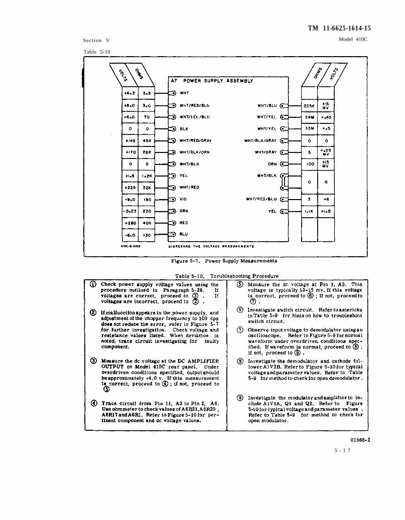
Figure 5-7.
Table 5-10.
Paragraph 5-29
Figure 5-10
Figure 5-7
Table 5-9
Figure 5-10 Figure 5-10
Table 5-9
TM 11-6625-1614-15
Section V Model 410C
Table 5-10
5 - 1 7

TM 11-6625-1614-15 Model 410C
Figure 5-11. Model 11036A AC Probe (Exploded View)
5-22
Figure 5-12. Model 11036A AC Probe Schematic
01556-2
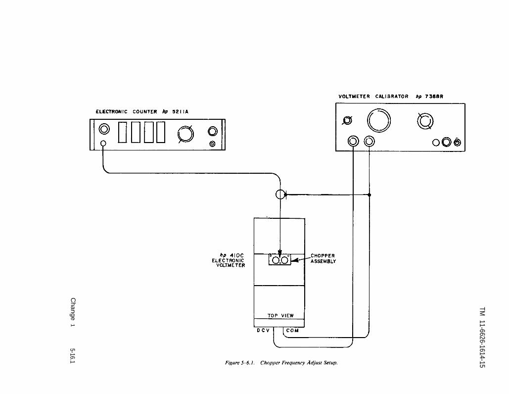
Figure 5-6.1.
TM 11-6626-1614-15
Change
15-16.1


TM 11-6625-1614-15Section VFigure 5-8
Figure 5-8.
Power Supply Schematic
5-19

5-20
TM 11-6625-1614-15
Figure 5-9. Typical Amplifier Waveforms


By Order of the secretary of the Army:
O f f i c i a l :KENNETH G. WICKHAM,Major General, United States Army,The Adjutant General.
Distribution:
Active Army;
USAMB (1)USACDCEC (.1)USACDCCEA (1)USA CDCCEA Ft Huachuca (1)
NG: None.
USAR: None.
For explanation of abbreviations used, see AR 320-50.
HAROLD K. JOHNSON,General, United States Army,Chief of Staff.
Eighth USA (5)SAAD (5)TOAD (5)LEAD (3)


THE METRIC SYSTEM AND EQUIVALENTS

PIN: 016288-000