Prioritizing Booster Pump Station Improvements Tom Peters, P.E. May 2, 2008.
Southwest Pump Station Improvements Project 10413/63903
ADD 1-0
BID PROJECT NO. 0102-17
MONROE COUNTY, NEW YORK
ADDENDUM NO. 2
TO THE CONTRACT DOCUMENTS
FOR CONSTRUCTION OF
SOUTHWEST PUMP STATION IMPROVEMENTS PROJECT
January 24, 2017
Contract No. P - Plumbing Contract No. H - HVAC
Contract No. E - Electrical
Prepared By: O’Brien & Gere 400 Andrews Street, Suite 710 Rochester, New York 14604
Prepared For: Monroe County Department of Environmental Services 50 West Main Street, Suite 7100 Rochester, New York 14614
Southwest Pump Station Improvements Project 10413/63903
ADD 1-1
TO ALL HOLDERS OF CONTRACT DOCUMENTS: Your attention is directed to the following interpretations of, changes in, and additions to the Contract Documents for the construction of the Southwest Pump Station Improvements Project.
This addendum is issued in accordance with Article 4 of the Instructions to Bidders, and is made part of the Contract Documents in accordance with Article I of the Agreement. CONTRACTOR shall acknowledge receipt of this Addendum in the space provided on the Proposal form; failure to do so may subject the Bidder to disqualification.
A. IN THE FRONT END DOCUMENTS
1. In the Table of Contents, Page TOC-3, under Division 6 – Carpentry, ADD the following:
“06 60 00 Fiberglass Grating
06 61 00 Glass Fiber and Resin (FRP) Fabrication”
B. IN THE SUPPLEMENTAL INFORMATION
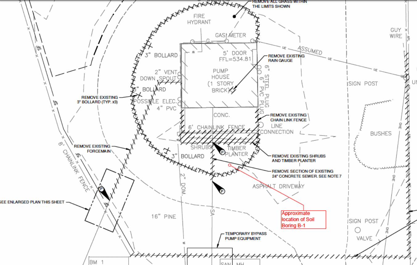
1. ADD the Subsurface Log for the Southwest Pump Station, Hole No. B-1, dated January 18, 2017, prepared by SJB Services, Inc. and the Soil Boring Location Map, copies of which are attached hereto and made part of this addendum.
C. IN THE TECHNICAL SPECIFICATIONS
1. ADD Section 06 60 00 – Fiberglass Grating, a copy of which is attached hereto and made part of this addendum.
2. ADD Section 06 61 00 – Glass Fiber and Resin (FRP) Fabrication, a copy of which is attached hereto and made part of this addendum.
3. DELETE Section 32 31 13 – Decorative Metal Fences and Gates in its entirety and SUBSTITUTE THEREFOR the attached Section 32 31 13 – Decorative Metal Fences and Gates, a copy of which is attached hereto and made part of this addendum.
4. In Section 40 05 23 – Process Valves Three Inches and Larger, DELETE Article 2.3.E in its entirety and SUBSTITUTE THEREFOR the following:
“E. DC Powered Actuators
1. Electrical equipment of the actuator shall be housed in a non-intrusive NEMA 4 or NEMA 6 watertight enclosure.
2. Motors shall be a low inertia, permanent magnet design and class F insulated rated for 15 minutes at average load.
3. Actuators shall be provided with a torque switch and temperature motor thermostats embedded in the motor windings.
4. Emergency Shutdown System Console
a. Each actuator shall be provided with an emergency shutdown system console

Southwest Pump Station Improvements Project 10413/63903
ADD 1-2
that provides 110V DC power from a 220/ 240 V AC supply.
b. Each emergency shutdown system console shall include the following:
i. AC power supply monitor relay
ii. Common fault alarm contact
iii. Indication panel with LCD display
iv. DC battery backup system with a battery life of 5 years/2000 cycles and a battery re-charge time of 2 hours. Battery backup system shall maintain valve operation in the event of AC main power failure.
c. Emergency shutdown system console shall be constructed of IP65 rated sheet steel and be suitable for wall mounting.
d. Emergency shutdown system consoles shall be supplied by Contract P and installed by Contract E.
5. DC powered actuators shall have a pressure range of 18 psi to 37 psi, with an average working pressure of 23 psi.
6. Actuators shall be Rotork IQD Actuators or approved equal.”
5. In Section 43 21 39 – Dry Pit Submersible Pumps, DELETE Article 2.5.A.2 in its entirety.
6. In Section 46 24 00 – Channel Grinder, in Article 2.3.A.1.b, DELETE “Channel grinder shall have two rotating screen drums” and SUBSTITUTE THEREFOR “Channel grinder shall have a single rotating screen drum”.
D. ON THE CONTRACT DRAWINGS
1. On Drawing G-102 (File No. 10413.63903-004, Revision 0), DELETE callout “3” Bollard (Typ. x6)” and SUBSTITUTE THEREFOR “6” Bollard (Typ. x5)”.
2. On Drawing G-102 (File No. 10413.63903-004, Revision 0), under General Notes, ADD the following:
“7. Existing groundwater well located in the Southwest corner of the site at a depth of 18 feet. Measured groundwater levels from the surface are as follows:
Low Groundwater Level: 6.3 feet Average Groundwater Level: 4.6 feet High Groundwater Level: 2.7 feet”
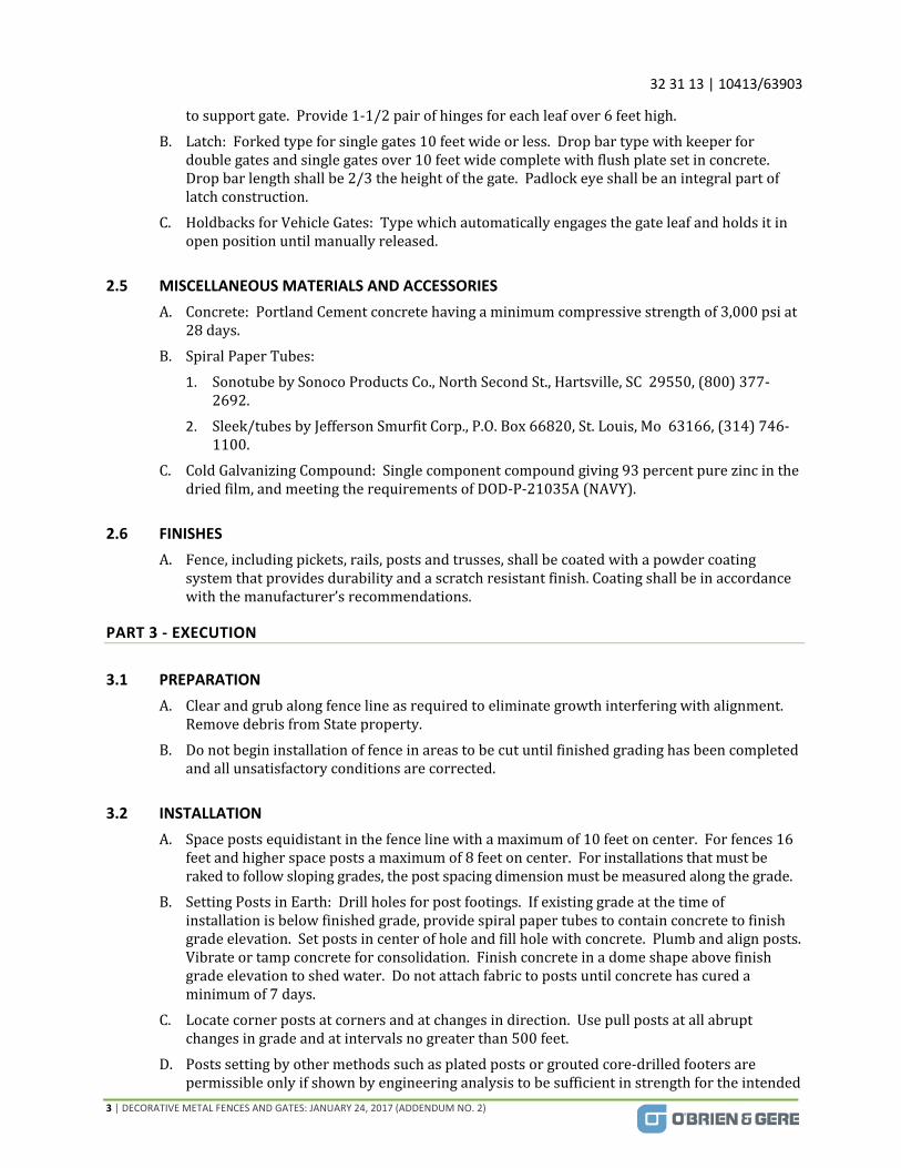
3. On Drawing S-101 (File No. 10413.63903-S101, Revision 0), in Demolition Plan at El. 534’8”, DELETE the callout “Remove exist. concrete slab” in its entirety and SUBSTITUTE THEREFOR “Remove exist. concrete slab and grating located at elevations 534’8” and 512’0” in its entirety. See Figure S-101A for demolition work at Elev. 512’0.” ADD Figure S-101A, a copy of which is attached hereto and made part of this addendum.
4. On Drawing S-102 (File No. 10413.63903-S102, Revision 0), in the Floor Plan at El. 505’8”, DELETE the callout “Additional concrete fillet at 24” influent pipe” and SUBSTITUTE THEREFOR “Additional concrete fillet at 24” influent pipe. Existing concrete fillets within

Southwest Pump Station Improvements Project 10413/63903
ADD 1-3
Wet Well to remain.”
5. On Drawing S-103 (File No. 10413.63903-S103, Revision 0), DELETE the callout “Alum. Removable Grating – See Plan Note 3” and SUBSTITUTE THEREFOR “FRP removable grating. See Plan Note 3.”
6. On Drawing S-103 (File No. 10413.63903-S103, Revision 0), in Plan Note 3, DELETE the first sentence in its entirety and SUBSTITUTE THEREFOR “Grating shall be fiberglass pultruded grating with 2” T Bearing bars spaced 1 ½” O.C.”
7. On Drawing S-301 (File No. 10413.63903-S301, Revision 0), in Section 1, DELETE “T/ Platform 517’-4 ¾”” and SUBSTITUTE THEREFOR “T/ Platform 516’-4 ¾”.”
8. On Drawing S-301 (File No. 10413.63903-S301, Revision 0), in Section 2, DELETE “T/ Platform 517’-4 ¾”” and SUBSTITUTE THEREFOR “T/ Platform 516’-4 ¾”.”
9. On Drawing S-302 (File No. 10413.63903-S302, Revision 0), in Section 1, DELETE “T/ Platform 517’-4 ¾”” and SUBSTITUTE THEREFOR “T/ Platform 516’-4 ¾”.”
10. On Drawing S-302 (File No. 10413.63903-S302, Revision 0), in Section 6, DELETE “T/ Platform 517’-4 ¾” and “Elev. 517.39, 517’-4 ¾”” and SUBSTITUTE THEREFOR “T/ Platform 516’-4 ¾”.”
11. On Drawing S-302 (File No. 10413.63903-S302, Revision 0), in Section 9, DELETE “T/ Platform 517’-4 ¾” and “Elev. 517.39, 517’-4 ¾”” and SUBSTITUTE THEREFOR “T/ Platform 516’-4 ¾”.”
12. On Drawing A-202 (File No. 10413.63903-133, Revision 0), in the West Elevation, DELETE the callout, “(4) panel fiberglass mock door and frame sealed shut” and SUBSTITUTE THEREFOR “Hollow metal mock door and frame sealed shut.”
13. On Drawing A-501 (File No. 10413.63903-134, Revision 0), in Eave Detail C, DELETE the callout “Standing seam metal roof with 30# felt underlayment and exterior grade 5/8” plywood decking” and SUBSTITUTE THEREFOR “Standing seam metal roof with 30# felt underlayment and exterior grade ¾” plywood decking.”
14. On Drawing P-102 (File No. 10413.63903-202, Revision 0), in Floor Plan at Elev. 534’8”, on the 1” diameter section of water piping located downstream of the backflow preventer that exits the building along the north wall, DELETE the callout “1”” and SUBSTITUTE THEREFOR “1 ½”.”
15. On Drawing P-102 (File No. 10413.63903-202, Revision 0), in Drawing Note 14, DELETE “Transition to 2” above floor.”
16. On Drawing P-102 (File No. 10413.63903-202, Revision 0), in Drawing Note 17, DELETE “1” male hose end adapter” and SUBSTITUTE THEREFOR “1½” male hose end adapter.”
17. On Drawing E-104 (File No. 10413-63903-355, Revision 0), in the Panelboard Schedule in Row 17C, DELETE “Blank” and SUBSTITUTE THEREFOR “Existing Groundwater System, 15A/1P.”
Southwest Pump Station Improvements Project 10413/63903
ADD 1-4
18. On Drawing E-105 (File No. 10413-63903-356, Revision 0), in Keynote 1, ADD “Rain gauge shall be mounted on a Type 304 stainless steel pole with Type 304 stainless steel hardware. Pole shall be 6 feet tall and have a minimum diameter of 6-inches. Pole shall be secured below grade in a 4,500 psi concrete encasement extending a minimum of 4’0” below grade and a minimum of 6-inches below the bottom of the pole. Concrete encasement shall have a minimum overall diameter of 1’6”.”
19. On Drawing E-105 (File No. 10413-63903-356, Revision 0), in Keynote 3 DELETE the first sentence in its entirety and SUBSTITUTE THEREFOR “Provide (1) 1” conduit with (2) #12 AWG and #12 GND cable for signaling from Rain Gauge location to PLC Cabinet in Building. Provide (1) 1” conduit with (2) #12 AWG and #12 GND cable for signaling from Groundwater System location to PLC Cabinet in Building.”
20. On Drawing E-106 (File No. 10413-63903-357, Revision 0), in the Plan at Elevation 505’8”, DELETE TSL-230 and the associated callout in its entirety. In the Plan at Elevation 534’8”, ADD TSL-230 with callout “Temperature Sensor, Keynote 6” within the Control Room in the Northeast corner.
21. On Drawing E-106 (File No. 10413-63903-357, Revision 0), in the Keynotes, ADD the following:
“12. Existing fiber optic cable to be disconnected from the existing PLC location and reconnected to the proposed PLC location by OWNER. Contract E shall provide 4” RGS Conduit with pullrope for extension of fiber optic cable.
13. Three emergency shutdown system consoles for the DC actuated valves shall be supplied by Contract P and installed by Contract E. Consoles shall be installed along the south wall of the Dry Well.”
22. On Drawing E-106 (File No. 10413-63903-357, Revision 0), DELETE Keynote 7 in its entirety and SUBSTITUTE THEREFOR “Provide (1) ¾” RGS Conduit with (8) #14 AWG to PLC Cabinet. ¾” RGS Conduit with (3) #12 AWG + GND to emergency shutdown system console. ¾” RGS Conduit with (3) #12 AWG+GND from each emergency shutdown system console to junction box. 1” RGS Conduit with (3) #6 AWG to MCC.”
23. On Drawing E-106 (File No. 10413-63903-357, Revision 0), DELETE the wiring from FU-141, FU-142 and FU-143 to the junction boxes along the west wall of the Dry Well. DELETE the three junction boxes along the west wall of the Dry Well and the wiring connecting the junction boxes. ADD three emergency shutdown system consoles along the south wall of the Dry Well, west of the receptacle. ADD wiring from FU-141, FU-142, and FU-143 to an individual emergency shutdown console. ADD wiring from each of the emergency shutdown system consoles to a junction box located above the consoles. From the junction box, install wiring along the south and west wall until the callout “Conduit up to MCC.”
24. On Drawing E-108 (File No. 10413-63903-359, Revision 0), in the Panelboard Schedule in Row 17C, DELETE “Blank” and SUBSTITUTE THEREFOR “Existing Groundwater System, 15A/1P”.
Southwest Pump Station Improvements Project 10413/63903
ADD 1-5
Attachments
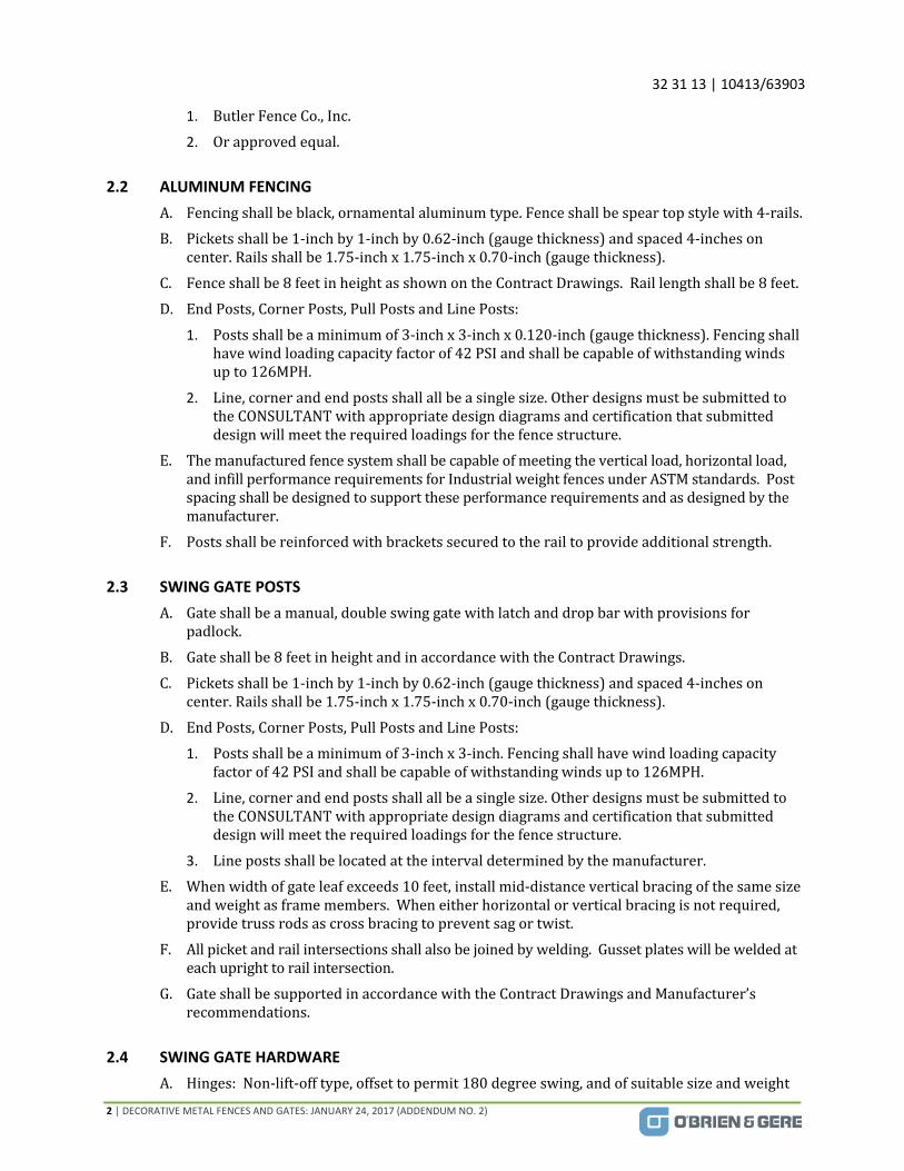
1. Subsurface Log for the Southwest Pump Station, Hole No. B-1, dated January 18, 2017, prepared by SJB Services, Inc. and the Soil Boring Location Map.
2. Section 06 60 00 – Fiberglass Grating.
3. Section 06 61 00 – Glass Fiber and Resin (FRP) Fabrication
4. Section 32 31 13 – Decorative Metal Fences and Gates
5. Figure S-101A – Demolition work at Elev. 512’0”
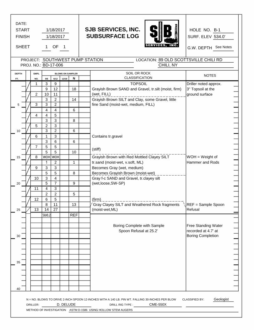
START SJB SERVICES, INC. HOLE NO. B-1
FINISH SUBSURFACE LOG SURF. ELEV 534.0'
SHEET 1 OF 1 G.W. DEPTH See Notes
LOCATION:
DEPTH SMPL BLOWS ON SAMPLER
FT. NO. 0/6 6/12 12/18 N
1 3 99 12 18
2 10 113 2 14
5 3 3 2
4 4 64 4 5
3 3 85 2 3
10 3 2 6
6 1 33 6 6
7 5 55 5 10
15 8 WOH WOH1 2 1
9 3 35 5 8
10 3 420 5 7 9
11 4 3
2 2 512 6 5
8 11 1325 13 14 27
50/0.2 REF
30
35
40
N = NO. BLOWS TO DRIVE 2-INCH SPOON 12-INCHES WITH A 140 LB. PIN WT. FALLING 30-INCHES PER BLOW CLASSIFIED BY: Geologist
DRILLER: DRILL RIG TYPE :
METHOD OF INVESTIGATION ASTM D-1586 USING HOLLOW STEM AUGERS
(stiff)
(wet,loose,SW-SP)
Becomes Gray (wet, medium)Becomes Grayish Brown (moist-wet)
tr.sand (moist-wet, v.soft, ML)
1/18/2017
1/18/2017
(wet, FILL)
PROJECT: PROJ. NO.:
SOIL OR ROCKNOTES
DATE:
SOUTHWEST PUMP STATIONBD-17-006
89 OLD SCOTTSVILLE CHILI RDCHILI, NY
Grayish Brown SILT and Clay, some Gravel, little
TOPSOILGrayish Brown SAND and Gravel, tr.silt (moist, firm)
CLASSIFICATION
Contains tr.gravel
Refusal
WOH = Weight of
Hammer and Rods
REF = Sample Spoon
ground surface
fine Sand (moist-wet, medium, FILL)
Gray f-c SAND and Gravel, tr.clayey silt
Boring Completion
Driller noted approx. 3" Topsoil at the
recorded at 4.7' atFree Standing Water
D. DELUDE CME-550X
(moist-wet,ML)
(firm)
Grayish Brown with Red Mottled Clayey SILT
Boring Complete with SampleSpoon Refusal at 25.2'
Gray Clayey SILT and Weathered Rock fragments
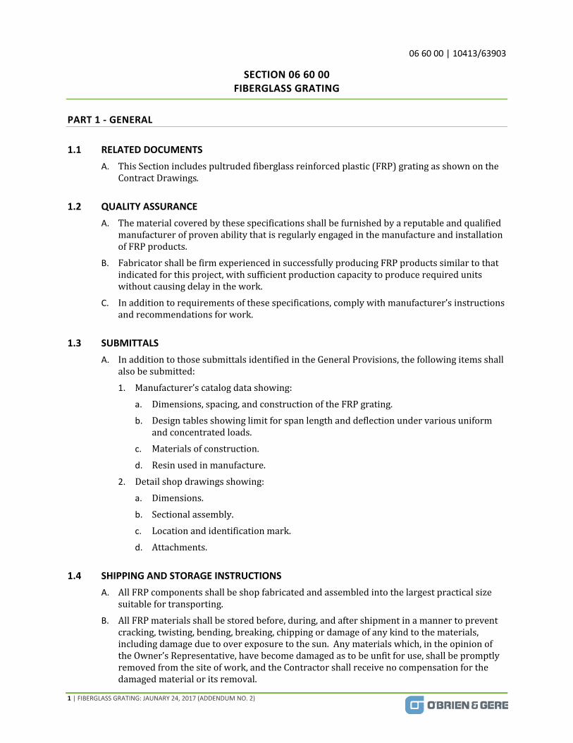
06 60 00 | 10413/63903
1 | FIBERGLASS GRATING: JAUNARY 24, 2017 (ADDENDUM NO. 2)
SECTION 06 60 00 FIBERGLASS GRATING
PART 1 ‐ GENERAL
1.1 RELATED DOCUMENTS
A. ThisSectionincludespultrudedfiberglassreinforcedplastic(FRP)gratingasshownontheContractDrawings.
1.2 QUALITY ASSURANCE
A. ThematerialcoveredbythesespecificationsshallbefurnishedbyareputableandqualifiedmanufacturerofprovenabilitythatisregularlyengagedinthemanufactureandinstallationofFRPproducts.
B. FabricatorshallbefirmexperiencedinsuccessfullyproducingFRPproductssimilartothatindicatedforthisproject,withsufficientproductioncapacitytoproducerequiredunitswithoutcausingdelayinthework.
C. Inadditiontorequirementsofthesespecifications,complywithmanufacturer’sinstructionsandrecommendationsforwork.
1.3 SUBMITTALS
A. InadditiontothosesubmittalsidentifiedintheGeneralProvisions,thefollowingitemsshallalsobesubmitted:
1. Manufacturer’scatalogdatashowing:
a. Dimensions,spacing,andconstructionoftheFRPgrating.
b. Designtablesshowinglimitforspanlengthanddeflectionundervariousuniformandconcentratedloads.
c. Materialsofconstruction.
d. Resinusedinmanufacture.
2. Detailshopdrawingsshowing:
a. Dimensions.
b. Sectionalassembly.
c. Locationandidentificationmark.
d. Attachments.
1.4 SHIPPING AND STORAGE INSTRUCTIONS
A. AllFRPcomponentsshallbeshopfabricatedandassembledintothelargestpracticalsizesuitablefortransporting.
B. AllFRPmaterialsshallbestoredbefore,during,andaftershipmentinamannertopreventcracking,twisting,bending,breaking,chippingordamageofanykindtothematerials,includingdamageduetooverexposuretothesun.Anymaterialswhich,intheopinionoftheOwner’sRepresentative,havebecomedamagedastobeunfitforuse,shallbepromptlyremovedfromthesiteofwork,andtheContractorshallreceivenocompensationforthedamagedmaterialoritsremoval.

06 60 00 | 10413/63903
2 | FIBERGLASS GRATING: JAUNARY 24, 2017 (ADDENDUM NO. 2)
C. Identifyandmatch‐markallmaterials,items,andfabricationsforinstallationandfieldassembly.
PART 2 ‐ PRODUCTS
2.1 MANUFACTURERS
A. ThefollowingmanufacturersarenamedtoestablishastandardofqualitynecessaryfortheProject:
1. StrongwellCo.
2. Fibergrate.
3. McNicholsCo.
4. AmericanGrating,LLC
5. DeltaComposites,LLC
6. IKGIndustries
7. Orequal.
B. FRPproductsusedonthisprojectshallbefromthesamemanufacturerunlessotherwisenotedintheContractDocuments.
2.2 GENERAL
A. MaterialsusedinthemanufactureoftheFRPgratingshallbenewstockofthebestqualityandshallbefreefromalldefectsandimperfectionsthatmightaffecttheperformanceofthefinishedproduct.
B. Afterfabrication,allcutends,holesandabrasionsofFRPgratingshallbesealedwithacompatibleresincoatingtopreventintrusionofmoisture.
C. FRPgratingexposedtoweathershallcontainanultravioletinhibitorandshallalsoreceiveasurfacingveiltoshieldfromultra‐violetlight.
D. Allexposedsurfacesshallbesmoothandtruetoform.Walkingsurfaceshallbegrittedforskidresistance.
2.3 PERFORMANCE REQUIREMENTS
A. UnlessotherwisenotedontheContractDrawings,gratingshallsupportaminimumuniformlydistributedpersonnelloadingof100lbs./sq.ft.withdeflectionnotexceeding0.25inchesforthespansindicatedontheContractDrawings.
2.4 PANEL WEIGHT LIMITS
A. Gratingshallbeconstructedsuchthatnosinglepanelshallweighmorethan150lbsforinstallation/removal/re‐installation.
2.5 MATERIALS AND CONSTRUCTION
A. FRPGrating
1. Gratingshallbeshippedfromthemanufacturer,palletizedandbandedwithexposededgesprotectedbycardboardtopreventdamageinshipment.
2. Eachpieceshallbeclearlymarkedshowingmanufacturer’sapplicabledrawingnumber.
06 60 00 | 10413/63903
3 | FIBERGLASS GRATING: JAUNARY 24, 2017 (ADDENDUM NO. 2)
3. GratingshallbeconstructedofacombinationofFRPreinforcementsandthermosetting,fireretardant,vinylesterresin.Gratingshallbeproducedbythepultrusionprocess.Glasscontentshallbeapproximately60percentbyweight.Fibersshallbecompletelysurroundedbyacontinuousglassfibermat.
4. BearingbarsshallbeofthedepthindicatedontheContractDrawings.Crossbarsshallbechemicallybondedtothebearingbars.
5. Gratingcolorshallbegray.
6. Acceptablegratingproductsincludethefollowing:
a. “Duradeck”bytheStrongwellCo.
b. “Safe‐T‐Span”bytheFibergrateCorporation.
c. “PultrudedI‐BarbytheMcNicholsCo.
d. Orequal.PART 1 EXECUTION
PART 3 ‐ EXECUTION
3.1 INSTALLATION
A. InstallFRPgratingspecifiedasindicatedandinaccordancewithmanufacturer’sinstructions.
B. Sealcutendsofgratingwithmanufacturersrecommendedresin.
C. Securegratingtosupportingmembersusingthegratingmanufacturer’sstandardstainlesssteelattachment,spacedatthegratingmanufacturer’srecommendedspacingbutnotlessthantwoattachmentsateachsupportofeachsectionofgrating.
END OF SECTION
06 61 00 | 10413/63903
1 |GLASS FIBER AND RESIN (FRP) FABRICATIONSSELECT FILL : JAUNARY 24, 2017 (ADDENDUM NO. 2)
SECTION 06 61 00 GLASS FIBER AND RESIN (FRP) FABRICATIONS
PART 1 ‐ GENERAL
1.1 RELATED DOCUMENTS
A. ThisSectionincludesglassfiberandresin(FRP)fabricationsincludingaccessories.
1.2 QUALITY ASSURANCE
A. ThematerialcoveredbythesespecificationsshallbefurnishedbyareputableandqualifiedmanufacturerofprovenabilitywhohasregularlyengagedinthemanufactureandinstallationofFRPgratingandstructuralshapes.
B. FabricatingfirmshallbeexperiencedinsuccessfullyproducingFRPfabricationssimilartothatindicatedforthisproject,withsufficientproductioncapacitytoproducerequiredunitswithoutcausingdelayinthework.
C. Inadditiontorequirementsofthesespecifications,complywithmanufacturer'sinstructionsandrecommendationsforwork.
1.3 SUBMITTALS
A. InadditiontothosesubmittalsidentifiedintheGeneralProvisions,thefollowingitemsshallalsobesubmitted:
1. Manufacturer'scatalogdatashowing:
a. Dimensionsandconstructionofstructuralshapes.
B. Materialsofconstruction.
1. Detailshopdrawingsshowing:
a. Dimensionsofstructuralshapes.
b. Sectionalassembly
c. Locationandidentificationmarks
1.4 DELIVERY, STORAGE AND HANDLING
A. Allstructuralshapesshallbeshop‐fabricated.
B. Allmaterialsandequipmentnecessaryforthefabricationandinstallationofthestructuralshapesshallbestoredbefore,during,andaftershipmentinamannertopreventcracking,twisting,bending,breaking,chippingordamageofanykindtothematerialsorequipment,includingdamageduetooverexposuretothesun.Anymaterialwhich,intheopinionoftheCommission,hasbecomedamagedastobeunfitforuse,shallbepromptlyremovedfromthesiteofwork,andtheContractorshallreceivenocompensationforthedamagedmaterialoritsremoval.
C. Identifyandmatch‐markallmaterials,items,andfabricationsforinstallationandfieldassembly.
06 61 00 | 10413/63903
2 |GLASS FIBER AND RESIN (FRP) FABRICATIONSSELECT FILL : JAUNARY 24, 2017 (ADDENDUM NO. 2)
PART 2 ‐ MATERIALS
2.1 MANUFACTURERS
A. ThefollowingmanufacturersarenamedtoestablishastandardofqualitynecessaryfortheProject:
1. Strongwell
2. FibergrateCompositeStructures
3. EnduroComposites,Inc.
4. StructuralFiberglass,Inc.
5. Orequal
2.2 MATERIALS AND CONSTRUCTION
A. StructuralShapes
1. Providestructuralshapesfabricatedwithfiberglassreinforcementandeitherpolyesterorvinylesterresins.
2. FRPStructuralShapeDesignRequirements
a. Minimumtensilestrengthshallbe30,000poundspersquareinch.
b. Minimummodulusofelasticityshallbe2,500,000poundspersquareinch.
c. IncludeUVinhibitorforfiberglassshapesexposedtosunlight.
3. FRPstructuralshapecolorshallbegray.
4. Provideasurfacingveiltoincreasecorrosionresistance.
5. Sealallcutends,holesandabrasionsofFRPstructuralshapeswithacompatibleresincoating.
B. Accessories
1. ProvidestainlesssteelboltsforconnectionsofFRPstructuralshapes.
PART 3 ‐ EXECUTION
3.1 PREPARATION
A. Examination
1. Examinesupportingsubstratesandadjacentconstructionforconditionsaffectinginstallationandperformanceofgratingsandstructuralshapes.
B. Installation
1. PerformcuttingandfittingrequiredforinstallationofFRPstructuralshapes.SetFRPstructuralshapesaccuratelyinlocation,alignment,andelevation;withedgesandsurfaceslevel,plumb,true,andfreeofrack;andmeasuredfromestablishedlinesandlevels.
a. Allfieldcutedgesandabrasionsshallbesealedwithacatalyzedresincompatiblewiththeoriginalresinasrecommendedbythemanufacturer.
b. Installspecifieditemsinaccordancewithmanufacturer'sinstructions.
END OF SECTION
32 31 13 | 10413/63903
1 | DECORATIVE METAL FENCES AND GATES: JANUARY 24, 2017 (ADDENDUM NO. 2)
SECTION 32 31 13 DECORATIVE METAL FENCES AND GATES
PART 1 ‐ GENERAL
1.1 RELATED DOCUMENTS
A. Themanufacturershallsupplyablack,aluminumornamentalfence.Fenceshallbe8feethighandlocatedasshownontheContractDrawings.
B. Drawings,GeneralConditions,SpecialConditionsandDivision32SpecificationsapplytothisSection.
1.2 REFERENCES
A. ComplywithASTMA53forrequirementsofSchedule40piping.
1.3 DEFINITIONS
A. HeightofFence:Distancemeasuredfromthetopofconcretefootingtothetopoffabric.
1.4 SUBMITTALS
A. ShopDrawings:Completedetaileddrawingsforeachheightandstyleoffenceandgaterequired.Includeseparatescheduleforeachlistingallmaterialsrequiredandtechnicaldatasuchassize,weight,andfinish,toensureconformancetospecifications.
B. ProductData:Manufacturer’scatalogcuts,specifications,andinstallationinstructionsforeachitemspecified.
C. Samples:
1. FenceFabric:Minimumonesquarefoot.
2. FenceandGatePosts:Twoeach,onefootlong,ifrequested.
3. MiscellaneousMaterialsandAccessories:Oneeach,ifrequested.
D. Manufacturer’slongtermwarrantyrequirements
E. Certifications:
1. Thealuminumweldersandweldingprocessmustbecertifiedpersection2.06D.
2. Manufacturershallsupplygatedesignperformancecertificationaspersection1.03C.
1.5 QUALITY ASSURANCE
A. Providealuminumfenceandrelatedgatesasacompletecompatiblesystemincludingnecessaryerectionaccessories,fittings,andfastenings.
B. Postsandrailsshallbecontinuouswithoutsplices.
PART 2 ‐ PRODUCTS
2.1 MANUFACTURERS
A. Thefollowingmanufacturersarenamedtoestablishastandardofqualitynecessaryfortheproject:
32 31 13 | 10413/63903
2 | DECORATIVE METAL FENCES AND GATES: JANUARY 24, 2017 (ADDENDUM NO. 2)
1. ButlerFenceCo.,Inc.
2. Orapprovedequal.
2.2 ALUMINUM FENCING
A. Fencingshallbeblack,ornamentalaluminumtype.Fenceshallbespeartopstylewith4‐rails.
B. Picketsshallbe1‐inchby1‐inchby0.62‐inch(gaugethickness)andspaced4‐inchesoncenter.Railsshallbe1.75‐inchx1.75‐inchx0.70‐inch(gaugethickness).
C. Fenceshallbe8feetinheightasshownontheContractDrawings.Raillengthshallbe8feet.
D. EndPosts,CornerPosts,PullPostsandLinePosts:
1. Postsshallbeaminimumof3‐inchx3‐inchx0.120‐inch(gaugethickness).Fencingshallhavewindloadingcapacityfactorof42PSIandshallbecapableofwithstandingwindsupto126MPH.
2. Line,cornerandendpostsshallallbeasinglesize.OtherdesignsmustbesubmittedtotheCONSULTANTwithappropriatedesigndiagramsandcertificationthatsubmitteddesignwillmeettherequiredloadingsforthefencestructure.
E. Themanufacturedfencesystemshallbecapableofmeetingtheverticalload,horizontalload,andinfillperformancerequirementsforIndustrialweightfencesunderASTMstandards.Postspacingshallbedesignedtosupporttheseperformancerequirementsandasdesignedbythemanufacturer.
F. Postsshallbereinforcedwithbracketssecuredtotherailtoprovideadditionalstrength.
2.3 SWING GATE POSTS
A. Gateshallbeamanual,doubleswinggatewithlatchanddropbarwithprovisionsforpadlock.
B. Gateshallbe8feetinheightandinaccordancewiththeContractDrawings.
C. Picketsshallbe1‐inchby1‐inchby0.62‐inch(gaugethickness)andspaced4‐inchesoncenter.Railsshallbe1.75‐inchx1.75‐inchx0.70‐inch(gaugethickness).
D. EndPosts,CornerPosts,PullPostsandLinePosts:
1. Postsshallbeaminimumof3‐inchx3‐inch.Fencingshallhavewindloadingcapacityfactorof42PSIandshallbecapableofwithstandingwindsupto126MPH.
2. Line,cornerandendpostsshallallbeasinglesize.OtherdesignsmustbesubmittedtotheCONSULTANTwithappropriatedesigndiagramsandcertificationthatsubmitteddesignwillmeettherequiredloadingsforthefencestructure.
3. Linepostsshallbelocatedattheintervaldeterminedbythemanufacturer.
E. Whenwidthofgateleafexceeds10feet,installmid‐distanceverticalbracingofthesamesizeandweightasframemembers.Wheneitherhorizontalorverticalbracingisnotrequired,providetrussrodsascrossbracingtopreventsagortwist.
F. Allpicketandrailintersectionsshallalsobejoinedbywelding.Gussetplateswillbeweldedateachuprighttorailintersection.
G. GateshallbesupportedinaccordancewiththeContractDrawingsandManufacturer’srecommendations.
2.4 SWING GATE HARDWARE
A. Hinges:Non‐lift‐offtype,offsettopermit180degreeswing,andofsuitablesizeandweight
32 31 13 | 10413/63903
3 | DECORATIVE METAL FENCES AND GATES: JANUARY 24, 2017 (ADDENDUM NO. 2)
tosupportgate.Provide1‐1/2pairofhingesforeachleafover6feethigh.
B. Latch:Forkedtypeforsinglegates10feetwideorless.Dropbartypewithkeeperfordoublegatesandsinglegatesover10feetwidecompletewithflushplatesetinconcrete.Dropbarlengthshallbe2/3theheightofthegate.Padlockeyeshallbeanintegralpartoflatchconstruction.
C. HoldbacksforVehicleGates:Typewhichautomaticallyengagesthegateleafandholdsitinopenpositionuntilmanuallyreleased.
2.5 MISCELLANEOUS MATERIALS AND ACCESSORIES
A. Concrete:PortlandCementconcretehavingaminimumcompressivestrengthof3,000psiat28days.
B. SpiralPaperTubes:
1. SonotubebySonocoProductsCo.,NorthSecondSt.,Hartsville,SC29550,(800)377‐2692.
2. Sleek/tubesbyJeffersonSmurfitCorp.,P.O.Box66820,St.Louis,Mo63166,(314)746‐1100.
C. ColdGalvanizingCompound:Singlecomponentcompoundgiving93percentpurezincinthedriedfilm,andmeetingtherequirementsofDOD‐P‐21035A(NAVY).
2.6 FINISHES
A. Fence,includingpickets,rails,postsandtrusses,shallbecoatedwithapowdercoatingsystemthatprovidesdurabilityandascratchresistantfinish.Coatingshallbeinaccordancewiththemanufacturer’srecommendations.
PART 3 ‐ EXECUTION
3.1 PREPARATION
A. Clearandgrubalongfencelineasrequiredtoeliminategrowthinterferingwithalignment.RemovedebrisfromStateproperty.
B. Donotbegininstallationoffenceinareastobecutuntilfinishedgradinghasbeencompletedandallunsatisfactoryconditionsarecorrected.
3.2 INSTALLATION
A. Spacepostsequidistantinthefencelinewithamaximumof10feetoncenter.Forfences16feetandhigherspacepostsamaximumof8feetoncenter.Forinstallationsthatmustberakedtofollowslopinggrades,thepostspacingdimensionmustbemeasuredalongthegrade.
B. SettingPostsinEarth:Drillholesforpostfootings.Ifexistinggradeatthetimeofinstallationisbelowfinishedgrade,providespiralpapertubestocontainconcretetofinishgradeelevation.Setpostsincenterofholeandfillholewithconcrete.Plumbandalignposts.Vibrateortampconcreteforconsolidation.Finishconcreteinadomeshapeabovefinishgradeelevationtoshedwater.Donotattachfabrictopostsuntilconcretehascuredaminimumof7days.
C. Locatecornerpostsatcornersandatchangesindirection.Usepullpostsatallabruptchangesingradeandatintervalsnogreaterthan500feet.
D. Postssettingbyothermethodssuchasplatedpostsorgroutedcore‐drilledfootersarepermissibleonlyifshownbyengineeringanalysistobesufficientinstrengthfortheintended

32 31 13 | 10413/63903
4 | DECORATIVE METAL FENCES AND GATES: JANUARY 24, 2017 (ADDENDUM NO. 2)
application.
E. Bracecornerposts,pullposts,endposts,andgatepoststoadjacentlinepostswithhorizontalrails.
F. Diagonallybracecornerposts,pullposts,endposts,andgatepoststoadjacentlinepostswithtrussrodsandturnbuckles.
G. Fencepanelsshallbeattachedtothepostswithbracketssuppliedbythemanufacturer.
H. Secureposttopsandaccessorieswithtamper‐resistantscrews.
I. Installgatesplumbandlevelandadjustforfullopeningwithoutinterference.Installground‐setitemsinconcreteforanchorage,asrecommendedbyfencemanufacturer.Adjusthardwareforsmoothoperationandlubricatewherenecessary.
J. Restoredisturbedgroundareastooriginalcondition.Topsoilandseedtomatchadjacentareas.
END OF SECTION

EXISTINGSUMP (TYP)
EXISTINGCONCRETEWALL
EXISTINGCONCRETESLAB
DRY WELL103
WET WELL104
REMOVE EXISTING CONCRETE INTERMEDIATE FLOOR SLABAND GRATING AT APPROX. ELEV. 512.00' (CONTRACTOR TOFIELD VERIFY). SEE SUPPLEMENTAL INFORMATION FORSELECT DRAWINGS FROM GATES CHILI OGDEN SEWERDISTRICT PROJECT NUMBER 1070L. SEE PHOTOS 1 & 2ON M-102. SEE NOTE 1.
PLAN NOTES:1. SAWCUT EXISTING INTERMEDIATE FLOOR SLAB TO PERIMETER WALLS OF THE EXISTING WET WELL STRUCTURE TO REMAIN. EXISTING SURFACES SHALL BE CUT SMOOTH AND HAVE EXPOSED REBAR SURFACES TREATED IN ACCORDANCE WITH SECTION "CUTTING AND PATCHING".
1/4" = 1'-0"
DEMOLITION PLAN AT ELEV. 515'-0"2' 4'2'04'