Sound Enclosure Assembly Instructions
17
M773LW3 Sound Enclosure Assembly Instructions www.northern-lights.com Corporate Headquarters 4420 14th Avenue NW Seattle, WA 98107 Tel: (206) 789-3880 Fax: (206) 782-5455 Southeastern U.S.A. 1419 W Newport Center Dr Deerfield Beach, FL 33442 Tel: (954) 421-1717 Fax: (954) 421-1712 Alaska Branch Office 1200 West International Airport Road Anchorage, AK 99519 Tel: (907) 562-2222 Fax: (907) 563-1921 East Coast Branch 15 Aegean Dr. Suite 4 Methuen MA 01844 Tel: (978) 475-7400 Fax: (978) 475-7745 Gulf Branch 19 Veterans Memorial Blvd. Kenner, LA 70062 Tel: (504) 360-2180 Toll Free: (800) 843-6140
Transcript of Sound Enclosure Assembly Instructions

M773LW3Sound Enclosure Assembly Instructions
www.northern-lights.com
Corporate Headquarters4420 14th Avenue NWSeattle, WA 98107Tel: (206) 789-3880Fax: (206) 782-5455
Southeastern U.S.A.1419 W Newport Center DrDeerfield Beach, FL 33442Tel: (954) 421-1717Fax: (954) 421-1712
Alaska Branch Office1200 West InternationalAirport RoadAnchorage, AK 99519Tel: (907) 562-2222Fax: (907) 563-1921
East Coast Branch15 Aegean Dr. Suite 4Methuen MA 01844Tel: (978) 475-7400Fax: (978) 475-7745
Gulf Branch19 Veterans Memorial Blvd.Kenner, LA 70062 Tel: (504) 360-2180 Toll Free: (800) 843-6140

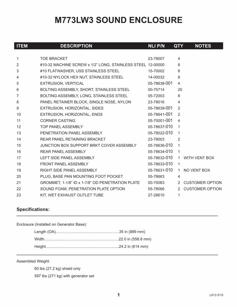
M773LW3 SOUND ENCLOSURE
ITEM DESCRIPTION NLI P/N QTY NOTES
1 TOEBRACKET 23-78007 42 #10-32MACHINESCREWx1/2”LONG,STAINLESSSTEEL 12-00000 83 #10FLATWASHER,USSSTAINLESSSTEEL 15-70002 84 #10-32NYLOCKHEXNUT,STAINLESSSTEEL 14-00032 85 EXTRUSION,VERTICAL 05-78638-001 46 BOLTINGASSEMBLY,SHORT,STAINLESSSTEEL 00-75714 207 BOLTINGASSEMBLY,LONG,STAINLESSSTEEL 05-72003 88 PANELRETAINERBLOCK,SINGLENOSE,NYLON 23-78016 49 EXTRUSION,HORIZONTAL,SIDES 05-78639-001 210 EXTRUSION,HORIZONTAL,ENDS 05-78641-001 211 CORNERCASTING 05-70001-001 412 TOPPANELASSEMBLY 05-78637-010 113 PENETRATIONPANELASSEMBLY 05-78022-010 114 REARPANELRETAININGBRACKET 23-78003 215 JUNCTIONBOXSUPPORTBRKTCOVERASSEMBLY 05-78636-010 116 REARPANELASSEMBLY 05-78634-010 117 LEFTSIDEPANELASSEMBLY 05-78632-010 1 WITHVENTBOX18 FRONTPANELASSEMBLY 05-78633-010 119 RIGHTSIDEPANELASSEMBLY 05-78631-010 1 NOVENTBOX20 PLUG,BASEPANMOUNTINGFOOTPOCKET 55-78663 421 GROMMET,1-1/8”IDx1-7/8”ODPENETRATIONPLATE 00-70083 2 CUSTOMEROPTION22 SOUNDFOAM,PENETRATIONPLATEOPTION 55-78066 2 CUSTOMEROPTION23 KIT,WETEXHAUSTOUTLETTUBE 27-28610 1
Specifications:
Enclosure(InstalledonGeneratorBase):
Length(OA)...........................................................35in(889mm)
Width.....................................................................22.0in(558.8mm)
Height....................................................................24.2in(614mm)
AssembledWeight:
60lbs(27.2kg)shieldonly
597lbs(271kg)withgeneratorset
1 L6135/15
2
1
2
3
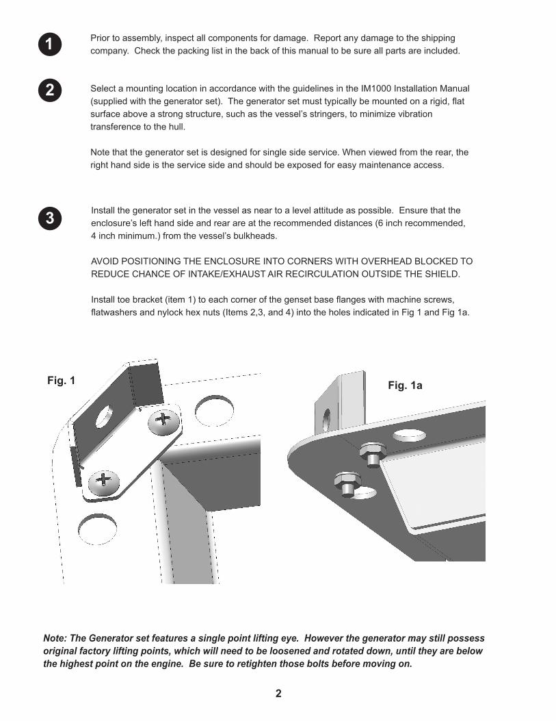
Priortoassembly,inspectallcomponentsfordamage.Reportanydamagetotheshippingcompany.Checkthepackinglistinthebackofthismanualtobesureallpartsareincluded.
Note: The Generator set features a single point lifting eye. However the generator may still possess original factory lifting points, which will need to be loosened and rotated down, until they are below the highest point on the engine. Be sure to retighten those bolts before moving on.
SelectamountinglocationinaccordancewiththeguidelinesintheIM1000InstallationManual(suppliedwiththegeneratorset).Thegeneratorsetmusttypicallybemountedonarigid,flatsurfaceaboveastrongstructure,suchasthevessel’sstringers,tominimizevibrationtransferencetothehull.
Notethatthegeneratorsetisdesignedforsinglesideservice.Whenviewedfromtherear,therighthandsideistheservicesideandshouldbeexposedforeasymaintenanceaccess.
Installthegeneratorsetinthevesselasneartoalevelattitudeaspossible.Ensurethattheenclosure’slefthandsideandrearareattherecommendeddistances(6inchrecommended,4inchminimum.)fromthevessel’sbulkheads.
AVOIDPOSITIONINGTHEENCLOSUREINTOCORNERSWITHOVERHEADBLOCKEDTOREDUCECHANCEOFINTAKE/EXHAUSTAIRRECIRCULATIONOUTSIDETHESHIELD.
Installtoebracket(item1)toeachcornerofthegensetbaseflangeswithmachinescrews,flatwashersandnylockhexnuts(Items2,3,and4)intotheholesindicatedinFig1andFig1a.
Fig. 1aFig. 1
3
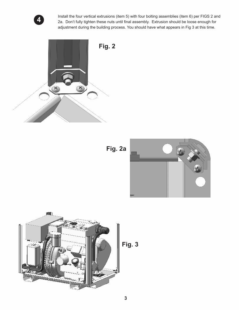
Fig. 2
Fig. 2a
Fig. 3
Installthefourverticalextrusions(item5)withfourboltingassemblies(item6)perFIGS2and2a.Don’tfullytightenthesenutsuntilfinalassembly.Extrusionshouldbelooseenoughforadjustmentduringthebuildingprocess.YoushouldhavewhatappearsinFig3atthistime.
4
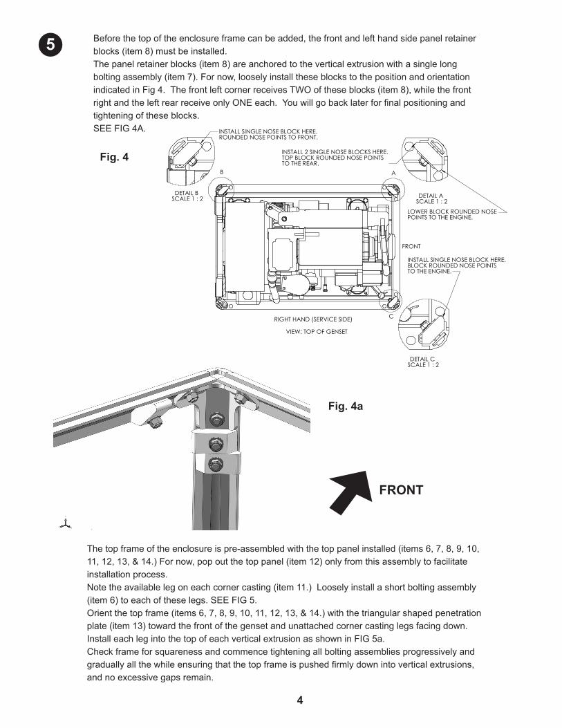
Beforethetopoftheenclosureframecanbeadded,thefrontandlefthandsidepanelretainerblocks(item8)mustbeinstalled.Thepanelretainerblocks(item8)areanchoredtotheverticalextrusionwithasinglelongboltingassembly(item7).Fornow,looselyinstalltheseblockstothepositionandorientationindicatedinFig4.ThefrontleftcornerreceivesTWOoftheseblocks(item8),whilethefrontrightandtheleftrearreceiveonlyONEeach.Youwillgobacklaterforfinalpositioningandtighteningoftheseblocks.SEEFIG4A.
Fig. 4a
Fig. 4
4
Thetopframeoftheenclosureispre-assembledwiththetoppanelinstalled(items6,7,8,9,10,11,12,13,&14.)Fornow,popoutthetoppanel(item12)onlyfromthisassemblytofacilitateinstallationprocess.Notetheavailablelegoneachcornercasting(item11.)Looselyinstallashortboltingassembly(item6)toeachoftheselegs.SEEFIG5.Orientthetopframe(items6,7,8,9,10,11,12,13,&14.)withthetriangularshapedpenetrationplate(item13)towardthefrontofthegensetandunattachedcornercastinglegsfacingdown.InstalleachlegintothetopofeachverticalextrusionasshowninFIG5a.Checkframeforsquarenessandcommencetighteningallboltingassembliesprogressivelyandgraduallyallthewhileensuringthatthetopframeispushedfirmlydownintoverticalextrusions,andnoexcessivegapsremain.
FRONT
5
DETAIL B SCALE 1 : 2
INSTALL SINGLE NOSE BLOCK HERE.ROUNDED NOSE POINTS TO FRONT.
DETAIL C SCALE 1 : 2
INSTALL SINGLE NOSE BLOCK HERE.BLOCK ROUNDED NOSE POINTS TO THE ENGINE.
VIEW: TOP OF GENSET
A
RIGHT HAND (SERVICE SIDE)
B
FRONT
C
DETAIL A SCALE 1 : 2
INSTALL 2 SINGLE NOSE BLOCKS HERE.TOP BLOCK ROUNDED NOSE POINTS TO THE REAR.
LOWER BLOCK ROUNDED NOSE POINTS TO THE ENGINE.

Nowinstallthejunctionboxsupportcover(item15)intoplace.Notetheshapeofthefoambackingandseethespacebeneaththegeneratorjunctionboxattherearofthegenset.SEEFIG6.InsertthefoamblockportionoftheJ-boxsupportcover(item15)intothecavityofthesupportbracketandpushuntilfirmlyengaged.SEEFIG6a.Whencorrectlyinstalled,thesupportcover(item15)shouldhaveaboutaninchoverlaponthegeneratorjunctionboxrearface.Theshapeofthefoaminsertisselfaligningandshouldholdthecoverinplace.Thepartmayappeartobepushingawayfromtherearfaceofthejunctionboxbut,oncetherearsoundshieldpanelisinstalled,thisunitwillbepushedbackintoposition.
5
Fig. 5 Fig. 5a
(ViewedfromBottom)
Notehowtheassemblyfitsinsideverticalextrusion.Fingertightenonlyuntilallfourcornershavebeenfullyinstalled.
Fig. 6 Fig. 6a
6
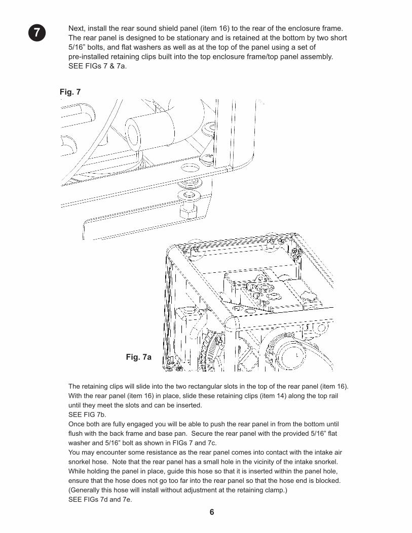
Next,installtherearsoundshieldpanel(item16)totherearoftheenclosureframe.Therearpanelisdesignedtobestationaryandisretainedatthebottombytwoshort5/16”bolts,andflatwashersaswellasatthetopofthepanelusingasetofpre-installedretainingclipsbuiltintothetopenclosureframe/toppanelassembly.SEEFIGs7&7a.
Theretainingclipswillslideintothetworectangularslotsinthetopoftherearpanel(item16).Withtherearpanel(item16)inplace,slidetheseretainingclips(item14)alongthetoprailuntiltheymeettheslotsandcanbeinserted.SEEFIG7b.Oncebotharefullyengagedyouwillbeabletopushtherearpanelinfromthebottomuntilflushwiththebackframeandbasepan.Securetherearpanelwiththeprovided5/16”flatwasherand5/16”boltasshowninFIGs7and7c.Youmayencountersomeresistanceastherearpanelcomesintocontactwiththeintakeairsnorkelhose.Notethattherearpanelhasasmallholeinthevicinityoftheintakesnorkel.Whileholdingthepanelinplace,guidethishosesothatitisinsertedwithinthepanelhole,ensurethatthehosedoesnotgotoofarintotherearpanelsothatthehoseendisblocked.(Generallythishosewillinstallwithoutadjustmentattheretainingclamp.)SEEFIGs7dand7e.
6
Fig. 7
Fig. 7a
7
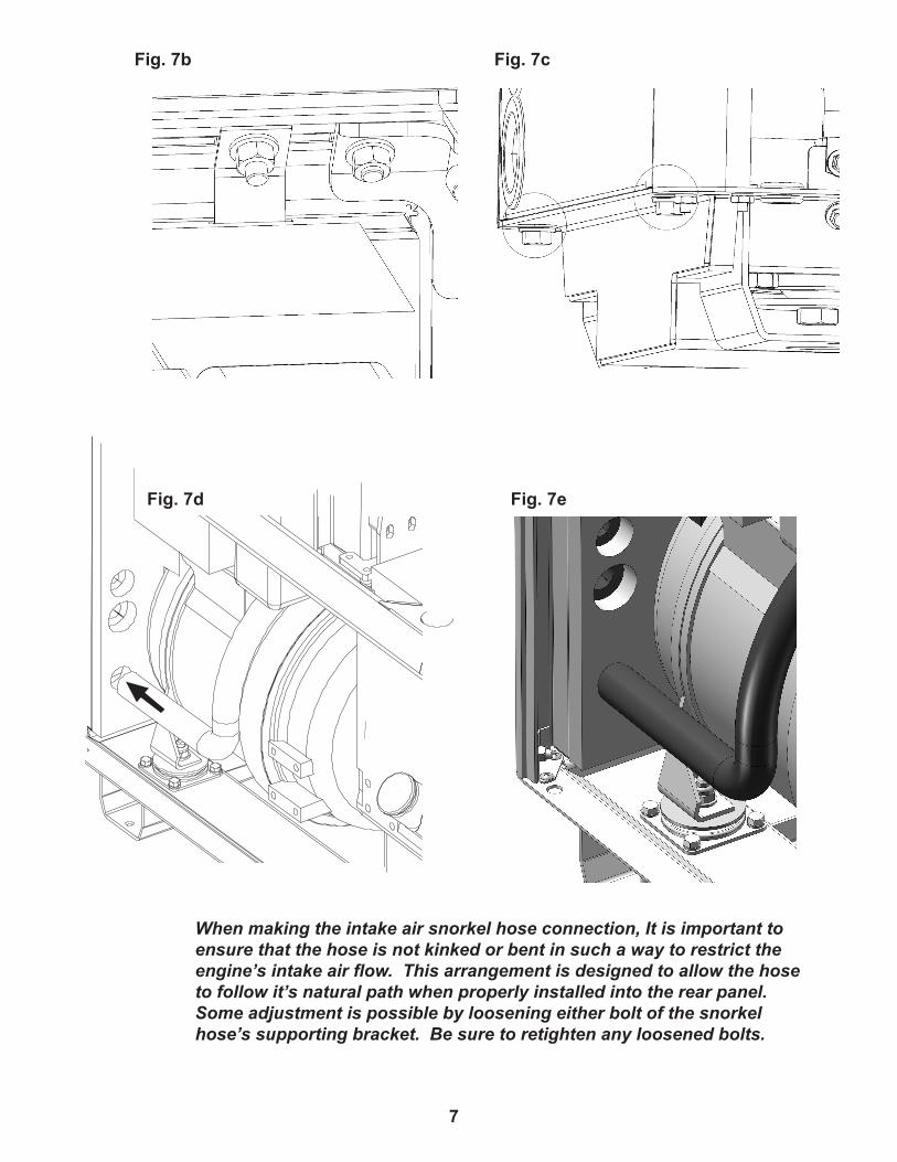
When making the intake air snorkel hose connection, It is important to ensure that the hose is not kinked or bent in such a way to restrict the engine’s intake air flow. This arrangement is designed to allow the hose to follow it’s natural path when properly installed into the rear panel. Some adjustment is possible by loosening either bolt of the snorkel hose’s supporting bracket. Be sure to retighten any loosened bolts.
7
Fig. 7b
Fig. 7d
Fig. 7c
Fig. 7e
8
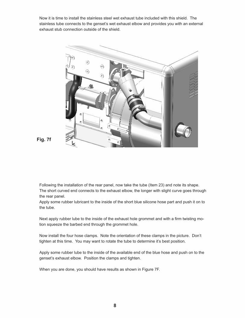
Followingtheinstallationoftherearpanel,nowtakethetube(Item23)andnoteitsshape.Theshortcurvedendconnectstotheexhaustelbow,thelongerwithslightcurvegoesthroughtherearpanel.Applysomerubberlubricanttotheinsideoftheshortbluesiliconehosepartandpushitontothetube.
Nextapplyrubberlubetotheinsideoftheexhaustholegrommetandwithafirmtwistingmo-tionsqueezethebarbedendthroughthegrommethole.
Nowinstallthefourhoseclamps.Notetheorientationoftheseclampsinthepicture.Don’ttightenatthistime.Youmaywanttorotatethetubetodetermineit’sbestposition.
Applysomerubberlubetotheinsideoftheavailableendofthebluehoseandpushontothegenset’sexhaustelbow.Positiontheclampsandtighten.
Whenyouaredone,youshouldhaveresultsasshowninFigure7F.
Nowitistimetoinstallthestainlesssteelwetexhausttubeincludedwiththisshield.Thestainlesstubeconnectstothegenset’swetexhaustelbowandprovidesyouwithanexternalexhauststubconnectionoutsideoftheshield.
Fig. 7f
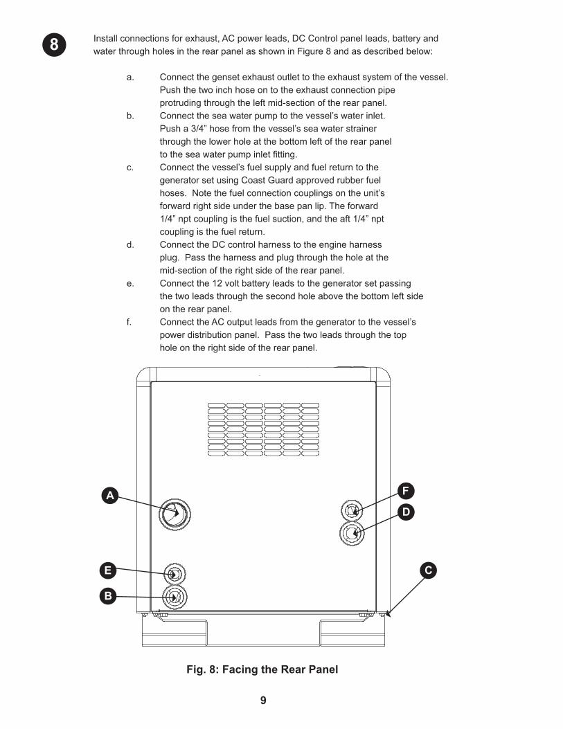
Installconnectionsforexhaust,ACpowerleads,DCControlpanelleads,batteryandwaterthroughholesintherearpanelasshowninFigure8andasdescribedbelow:
a. Connectthegensetexhaustoutlettotheexhaustsystemofthevessel. Pushthetwoinchhoseontotheexhaustconnectionpipe protrudingthroughtheleftmid-sectionoftherearpanel. b. Connecttheseawaterpumptothevessel’swaterinlet. Pusha3/4”hosefromthevessel’sseawaterstrainer throughthelowerholeatthebottomleftoftherearpanel totheseawaterpumpinletfitting. c. Connectthevessel’sfuelsupplyandfuelreturntothe generatorsetusingCoastGuardapprovedrubberfuel hoses.Notethefuelconnectioncouplingsontheunit’s forwardrightsideunderthebasepanlip.Theforward 1/4”nptcouplingisthefuelsuction,andtheaft1/4”npt couplingisthefuelreturn. d. ConnecttheDCcontrolharnesstotheengineharness plug.Passtheharnessandplugthroughtheholeatthe mid-sectionoftherightsideoftherearpanel. e. Connectthe12voltbatteryleadstothegeneratorsetpassing thetwoleadsthroughthesecondholeabovethebottomleftside ontherearpanel. f. ConnecttheACoutputleadsfromthegeneratortothevessel’s powerdistributionpanel.Passthetwoleadsthroughthetop holeontherightsideoftherearpanel.
9
Fig. 8: Facing the Rear Panel
8
A F
D
E C
B
10
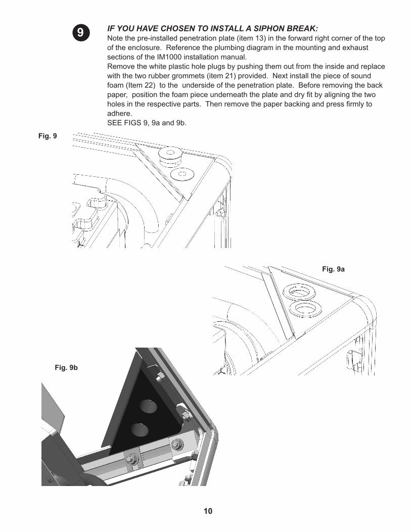
IF YOU HAVE CHOSEN TO INSTALL A SIPHON BREAK:Notethepre-installedpenetrationplate(item13)intheforwardrightcornerofthetopoftheenclosure.ReferencetheplumbingdiagraminthemountingandexhaustsectionsoftheIM1000installationmanual.Removethewhiteplasticholeplugsbypushingthemoutfromtheinsideandreplacewiththetworubbergrommets(item21)provided.Nextinstallthepieceofsoundfoam(Item22)totheundersideofthepenetrationplate.Beforeremovingthebackpaper,positionthefoampieceunderneaththeplateanddryfitbyaligningthetwoholesintherespectiveparts.Thenremovethepaperbackingandpressfirmlytoadhere.SEEFIGS9,9aand9b.
Fig. 9
Fig. 9b
Fig. 9a
9
a. Disconnectthehosefromtheseawaterpumpoutputandfrom therubberelbowontheexpansiontank.Installtwolengths of3/4”hose.Thehosesmustbeofadequatelengthtoallow mountingofasiphonbreak,aminimumof12inchesabovethe vessel’sloadedwaterline. b. Passtheseawaterpumpoutputhosethroughtheholeinthe penetrationplateclosesttothefrontoftheshield.Thehosefrom theexpansiontankmustgothroughtheholeinthepenetration plateclosesttothesideoftheshield. c. Formoreinformation,seethe“Exhaust”sectionoftheIM1000 InstallationManualincludedwiththegeneratorset.
11
CAUTION: GENERATOR SETS WITH WET EXHAUST THAT ARE INSTALLED NEAR OR BELOW THE VESSEL’S WATER LINE MUST USE A SIPHON BREAK TO PREVENT BACKFLOW OR WATER INTO THE ENGINE. THIS BACKFLOW CAN RUIN AN ENGINE AND POSSIBLY SINK THE VESSEL.Thepenetrationplate(item13)facilitatesthesiphonbreakinstallationasfollows:
Startthegeneratorsetandrununderloadtocheckforleaksoffuel,waterorexhaustgas.
Asyouinstallthepanels,observethatthereshouldbeaminimumclearanceofapproximately1/32”aroundthepanelparameter(exceptatthebottomofthesideandfrontpanels.)Youmayadjustforthisbylooseninganynumberofcornerboltingassembliesortoebracketsuntilfitissatisfactory.Tightenallconnectionswhendone.
Tosecuretheleftsidepanelandfrontpanelretainingblocks,installtheleftpanelinplace,takingnoteoftherectangularslotsoneachsideofthepanel.Slidetheretainingblocks(item8)uptheverticalextrusionlegsuntiltheblocksarecapturedbytheseslots.Proceedtotightentheboltingassemblywhileholdingtheblockinposition.Thendosimilarlyonthefrontpanel.Doensurethattheblockdoesnotrotateupontighteningasitmayaffectengagement.
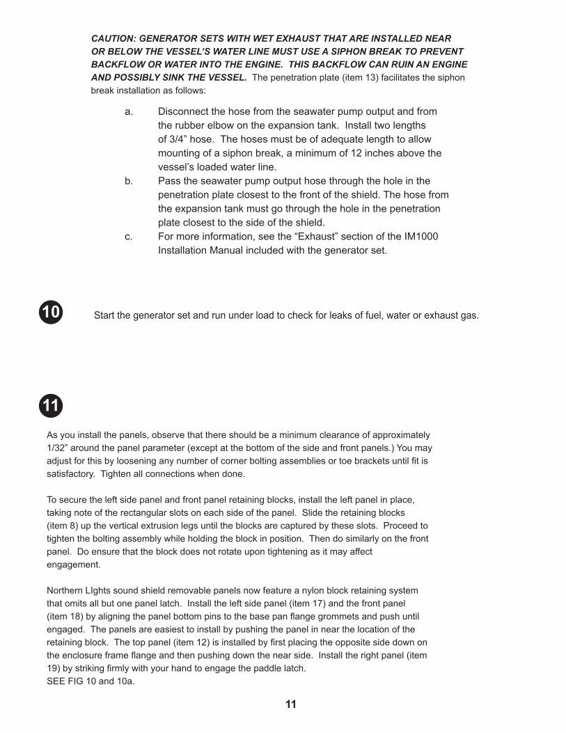
NorthernLIghtssoundshieldremovablepanelsnowfeatureanylonblockretainingsystemthatomitsallbutonepanellatch.Installtheleftsidepanel(item17)andthefrontpanel(item18)byaligningthepanelbottompinstothebasepanflangegrommetsandpushuntilengaged.Thepanelsareeasiesttoinstallbypushingthepanelinnearthelocationoftheretainingblock.Thetoppanel(item12)isinstalledbyfirstplacingtheoppositesidedownontheenclosureframeflangeandthenpushingdownthenearside.Installtherightpanel(item19)bystrikingfirmlywithyourhandtoengagethepaddlelatch.SEEFIG10and10a.
10
11
12
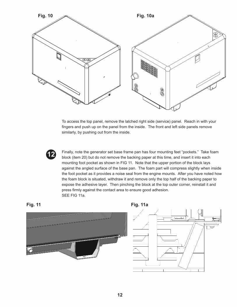
Finally,notethegeneratorsetbaseframepanhasfourmountingfeet“pockets.”Takefoamblock(item20)butdonotremovethebackingpaperatthistime,andinsertitintoeachmountingfootpocketasshowninFIG11.Notethattheupperportionoftheblocklaysagainsttheangledsurfaceofthebasepan.Thefoampartwillcompressslightlywheninsidethefootpocketasitprovidesanoisesealfromtheenginemounts.Afteryouhavenotedhowthefoamblockissituated,withdrawitandremoveonlythetophalfofthebackingpapertoexposetheadhesivelayer.Thenpinchingtheblockatthetopoutercorner,reinstallitandpressfirmlyagainstthecontactareatoensuregoodadhesion.SEEFIG11a.
Toaccessthetoppanel,removethelatchedrightside(service)panel.Reachinwithyourfingersandpushuponthepanelfromtheinside.Thefrontandleftsidepanelsremovesimilarly,bypushingoutfromtheinside.
Fig. 10
Fig. 11
Fig. 10a
Fig. 11a
12

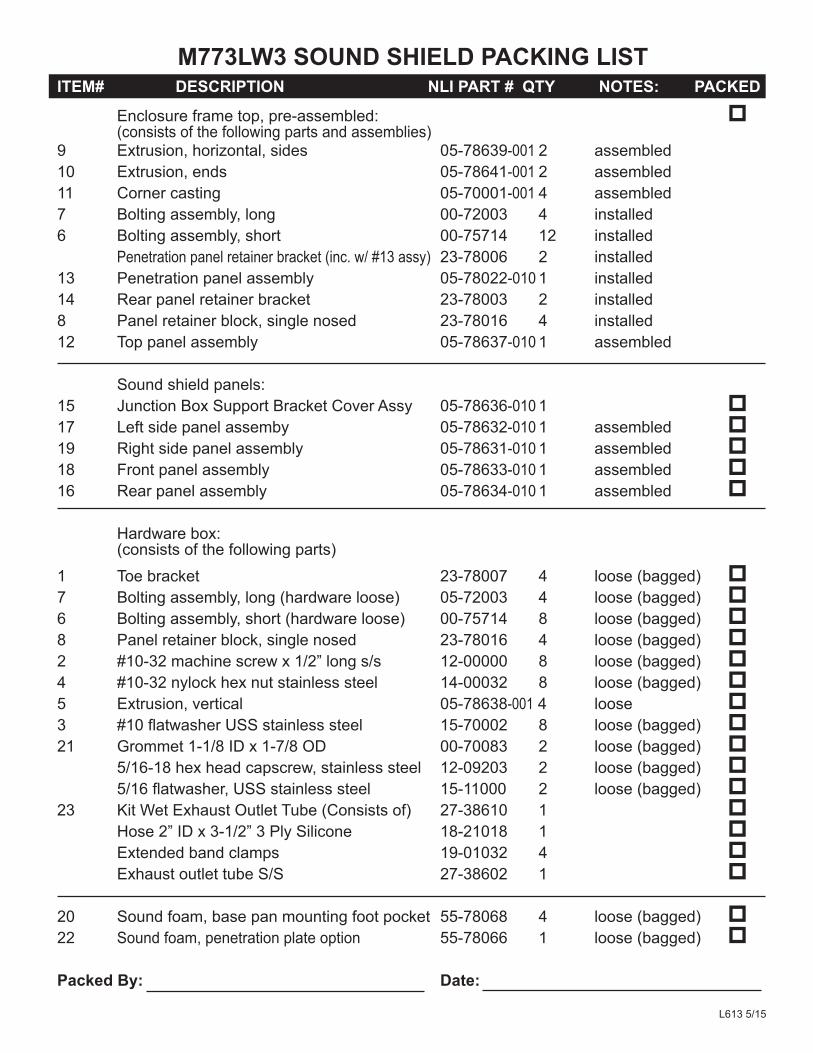
ITEM# DESCRIPTION NLI PART # QTY NOTES: PACKED Enclosureframetop,pre-assembled: p (consistsofthefollowingpartsandassemblies) 9 Extrusion,horizontal,sides 05-78639-0012 assembled 10 Extrusion,ends 05-78641-0012 assembled 11 Cornercasting 05-70001-0014 assembled 7 Boltingassembly,long 00-72003 4 installed 6 Boltingassembly,short 00-75714 12 installed Penetrationpanelretainerbracket(inc.w/#13assy) 23-78006 2 installed 13 Penetrationpanelassembly 05-78022-0101 installed 14 Rearpanelretainerbracket 23-78003 2 installed8 Panelretainerblock,singlenosed 23-78016 4 installed 12 Toppanelassembly 05-78637-0101 assembled Soundshieldpanels: 15 JunctionBoxSupportBracketCoverAssy 05-78636-0101 p17 Leftsidepanelassemby 05-78632-0101 assembled p19 Rightsidepanelassembly 05-78631-0101 assembled p18 Frontpanelassembly 05-78633-0101 assembled p16 Rearpanelassembly 05-78634-0101 assembled p Hardwarebox: (consistsofthefollowingparts) 1 Toebracket 23-78007 4 loose(bagged) p7 Boltingassembly,long(hardwareloose) 05-72003 4 loose(bagged) p6 Boltingassembly,short(hardwareloose) 00-75714 8 loose(bagged) p8 Panelretainerblock,singlenosed 23-78016 4 loose(bagged) p2 #10-32machinescrewx1/2”longs/s 12-00000 8 loose(bagged) p4 #10-32nylockhexnutstainlesssteel 14-00032 8 loose(bagged) p5 Extrusion,vertical 05-78638-0014 loose p3 #10flatwasherUSSstainlesssteel 15-70002 8 loose(bagged) p21 Grommet1-1/8IDx1-7/8OD 00-70083 2 loose(bagged) p 5/16-18hexheadcapscrew,stainlesssteel 12-09203 2 loose(bagged) p 5/16flatwasher,USSstainlesssteel 15-11000 2 loose(bagged) p23 KitWetExhaustOutletTube(Consistsof) 27-38610 1 p Hose2”IDx3-1/2”3PlySilicone 18-21018 1 p Extendedbandclamps 19-01032 4 p ExhaustoutlettubeS/S 27-38602 1 p 20 Soundfoam,basepanmountingfootpocket 55-78068 4 loose(bagged) p22 Soundfoam,penetrationplateoption 55-78066 1 loose(bagged) p
Packed By: Date:
M773LW3 SOUND SHIELD PACKING LIST
L6135/15
revised5-23-16
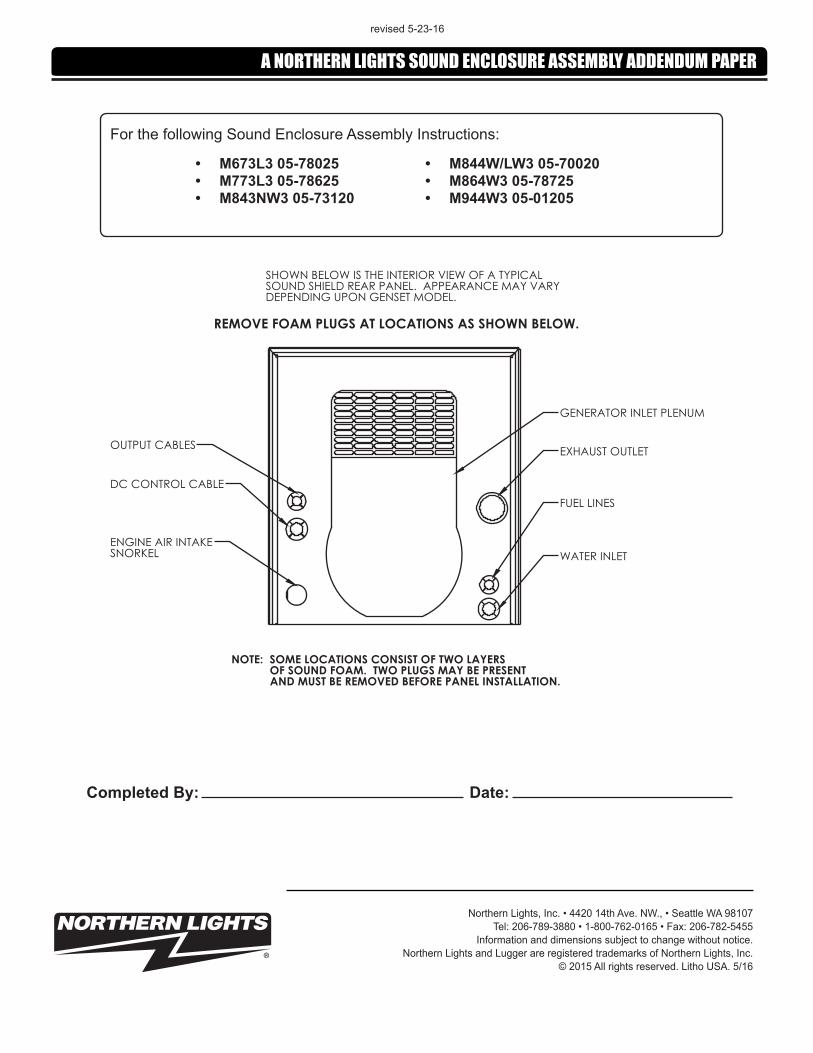
• M673L3 05-78025• M773L3 05-78625• M843NW3 05-73120
• M844W/LW3 05-70020• M864W3 05-78725• M944W3 05-01205
ForthefollowingSoundEnclosureAssemblyInstructions:
A NORTHERN LIGHTS SOUND ENCLOSURE ASSEMBLY ADDENDUM PAPER
WATER INLET
FUEL LINES
EXHAUST OUTLET
GENERATOR INLET PLENUM
OUTPUT CABLES
DC CONTROL CABLE
ENGINE AIR INTAKESNORKEL
NOTE: SOME LOCATIONS CONSIST OF TWO LAYERS OF SOUND FOAM. TWO PLUGS MAY BE PRESENT AND MUST BE REMOVED BEFORE PANEL INSTALLATION.
SHOWN BELOW IS THE INTERIOR VIEW OF A TYPICAL SOUND SHIELD REAR PANEL. APPEARANCE MAY VARY DEPENDING UPON GENSET MODEL.
REMOVE FOAM PLUGS AT LOCATIONS AS SHOWN BELOW.
Completed By: Date:
NorthernLights,Inc.•442014thAve.NW.,•SeattleWA98107Tel:206-789-3880•1-800-762-0165•Fax:206-782-5455
Informationanddimensionssubjecttochangewithoutnotice.NorthernLightsandLuggerareregisteredtrademarksofNorthernLights,Inc.
©2015Allrightsreserved.LithoUSA.5/16