SONET Topologies and Upgrades - · PDF fileSONET Topologies and Upgrades This chapter explains...
38
CHAPTER 12-1 Cisco ONS 15454 Reference Manual, R6.x 78-16890-01 12 SONET Topologies and Upgrades This chapter explains Cisco ONS 15454 SONET topologies and upgrades. To provision topologies, refer to the Cisco ONS 15454 Procedure Guide. Chapter topics include: • 12.1 SONET Rings and TCC2/TCC2P Cards, page 12-1 • 12.2 Bidirectional Line Switched Rings, page 12-2 • 12.3 Unidirectional Path Switched Rings, page 12-13 • 12.4 Dual-Ring Interconnect, page 12-18 • 12.5 Comparison of the Protection Schemes, page 12-25 • 12.6 Subtending Rings, page 12-26 • 12.7 Linear ADM Configurations, page 12-28 • 12.8 Path-Protected Mesh Networks, page 12-29 • 12.9 Four-Shelf Node Configurations, page 12-31 • 12.10 OC-N Speed Upgrades, page 12-32 • 12.11 In-Service Topology Upgrades, page 12-35 12.1 SONET Rings and TCC2/TCC2P Cards Table 12-1 shows the SONET rings that can be created on each ONS 15454 node using redundant TCC2/TCC2P cards. Table 12-1 ONS 15454 Rings with Redundant TCC2/TCC2P Cards Ring Type Maximum Rings per Node BLSRs 5 2-Fiber BLSR 5 4-Fiber BLSR 1 UPSR with SDCC 34 1 , 2 UPSR with LDCC 14 3 , 4
Transcript of SONET Topologies and Upgrades - · PDF fileSONET Topologies and Upgrades This chapter explains...

C78-16890-01
C H A P T E R 12
SONET Topologies and UpgradesThis chapter explains Cisco ONS 15454 SONET topologies and upgrades. To provision topologies, refer to the Cisco ONS 15454 Procedure Guide.
Chapter topics include:
• 12.1 SONET Rings and TCC2/TCC2P Cards, page 12-1
• 12.2 Bidirectional Line Switched Rings, page 12-2
• 12.3 Unidirectional Path Switched Rings, page 12-13
• 12.4 Dual-Ring Interconnect, page 12-18
• 12.5 Comparison of the Protection Schemes, page 12-25
• 12.6 Subtending Rings, page 12-26
• 12.7 Linear ADM Configurations, page 12-28
• 12.8 Path-Protected Mesh Networks, page 12-29
• 12.9 Four-Shelf Node Configurations, page 12-31
• 12.10 OC-N Speed Upgrades, page 12-32
• 12.11 In-Service Topology Upgrades, page 12-35
12.1 SONET Rings and TCC2/TCC2P CardsTable 12-1 shows the SONET rings that can be created on each ONS 15454 node using redundant TCC2/TCC2P cards.
Table 12-1 ONS 15454 Rings with Redundant TCC2/TCC2P Cards
Ring Type Maximum Rings per Node
BLSRs 5
2-Fiber BLSR 5
4-Fiber BLSR 1
UPSR with SDCC 341 ,2
UPSR with LDCC 143 ,4
12-1isco ONS 15454 Reference Manual, R6.x

Chapter 12 SONET Topologies and Upgrades12.2 Bidirectional Line Switched Rings
12.2 Bidirectional Line Switched RingsThe ONS 15454 can support five concurrent bidirectional line switch rings (BLSRs) in one of the following configurations:
• Five two-fiber BLSRs
• Four two-fiber and one four-fiber BLSR
Each BLSR can have up to 32 ONS 15454s. Because the working and protect bandwidths must be equal, you can create only OC-12 (two-fiber only), OC-48, or OC-192 BLSRs.
Note For best performance, BLSRs should have one LAN connection for every ten nodes in the BLSR.
12.2.1 Two-Fiber BLSRsIn two-fiber BLSRs, each fiber is divided into working and protect bandwidths. For example, in an OC-48 BLSR (Figure 12-1), STSs 1 to 24 carry the working traffic, and STSs 25 to 48 are reserved for protection. Working traffic (STSs 1 to 24) travels in one direction on one fiber and in the opposite direction on the second fiber. The Cisco Transport Controller (CTC) circuit routing routines calculate the shortest path for circuits based on many factors, including user requirements, traffic patterns, and distance. For example, in Figure 12-1, circuits going from Node 0 to Node 1 typically travel on Fiber 1, unless that fiber is full, in which case circuits are routed on Fiber 2 through Node 3 and Node 2. Traffic from Node 0 to Node 2 (or Node 1 to Node 3) can be routed on either fiber, depending on circuit provisioning requirements and traffic loads.
UPSR with LDCC and SDCC 265
1. Total SDCC usage must be equal to or less than 84 SDCCs.
2. See the “12.3 Unidirectional Path Switched Rings” section on page 12-13.
3. Total LDCC usage must be equal to or less than 28 LDCCs.
4. See the “12.3 Unidirectional Path Switched Rings” section on page 12-13.
5. Total LDCC and SDCC usage must be equal to or less than 84. When LDCC is provisioned, an SDCC termination is allowed on the same port, but is not recommended. Using SDCC and LDCC on the same port is only needed during a software upgrade if the other end of the link does not support LDCC. You can provision SDCCs and LDCCs on different ports in the same node.
Table 12-1 ONS 15454 Rings with Redundant TCC2/TCC2P Cards (continued)
Ring Type Maximum Rings per Node
12-2Cisco ONS 15454 Reference Manual, R6.x
78-16890-01

Chapter 12 SONET Topologies and Upgrades12.2.1 Two-Fiber BLSRs
Figure 12-1 Four-Node, Two-Fiber BLSR
The SONET K1, K2, and K3 bytes carry the information that governs BLSR protection switches. Each BLSR node monitors the K bytes to determine when to switch the SONET signal to an alternate physical path. The K bytes communicate failure conditions and actions taken between nodes in the ring.
If a break occurs on one fiber, working traffic targeted for a node beyond the break switches to the protect bandwidth on the second fiber. The traffic travels in a reverse direction on the protect bandwidth until it reaches its destination node. At that point, traffic is switched back to the working bandwidth.
Figure 12-2 shows a traffic pattern sample on a four-node, two-fiber BLSR.
Node 0
Node 1
Node 2
Node 3 OC-48 Ring
= Fiber 1
= Fiber 2 6193
8
STSs 1-24 (working)
STSs 25-48 (protect)
STSs 1-24 (working)
STSs 25-48 (protect)
12-3Cisco ONS 15454 Reference Manual, R6.x
78-16890-01
Chapter 12 SONET Topologies and Upgrades12.2.1 Two-Fiber BLSRs
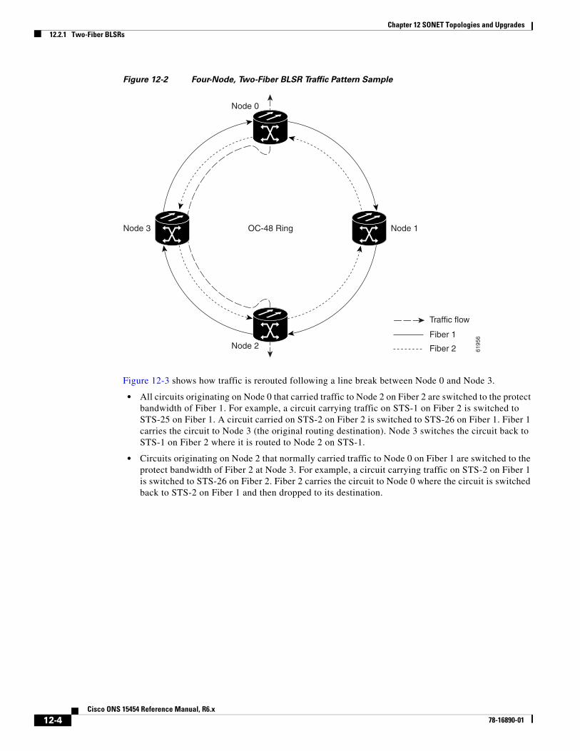
Figure 12-2 Four-Node, Two-Fiber BLSR Traffic Pattern Sample
Figure 12-3 shows how traffic is rerouted following a line break between Node 0 and Node 3.
• All circuits originating on Node 0 that carried traffic to Node 2 on Fiber 2 are switched to the protect bandwidth of Fiber 1. For example, a circuit carrying traffic on STS-1 on Fiber 2 is switched to STS-25 on Fiber 1. A circuit carried on STS-2 on Fiber 2 is switched to STS-26 on Fiber 1. Fiber 1 carries the circuit to Node 3 (the original routing destination). Node 3 switches the circuit back to STS-1 on Fiber 2 where it is routed to Node 2 on STS-1.
• Circuits originating on Node 2 that normally carried traffic to Node 0 on Fiber 1 are switched to the protect bandwidth of Fiber 2 at Node 3. For example, a circuit carrying traffic on STS-2 on Fiber 1 is switched to STS-26 on Fiber 2. Fiber 2 carries the circuit to Node 0 where the circuit is switched back to STS-2 on Fiber 1 and then dropped to its destination.
Node 0
Node 1
Traffic flow
Node 2
Node 3 OC-48 Ring
Fiber 1
Fiber 2 6195
6
12-4Cisco ONS 15454 Reference Manual, R6.x
78-16890-01

Chapter 12 SONET Topologies and Upgrades12.2.2 Four-Fiber BLSRs
Figure 12-3 Four-Node, Two-Fiber BLSR Traffic Pattern Following Line Break
12.2.2 Four-Fiber BLSRsFour-fiber BLSRs double the bandwidth of two-fiber BLSRs. Because they allow span switching as well as ring switching, four-fiber BLSRs increase the reliability and flexibility of traffic protection. Two fibers are allocated for working traffic and two fibers for protection, as shown in Figure 12-4. To implement a four-fiber BLSR, you must install four OC-48, OC-48 AS, or OC-192 cards at each BLSR node.
Node 0
Node 1
Node 2
Node 3 OC-48 Ring
6195
7
Traffic flow
Fiber 1
Fiber 2
12-5Cisco ONS 15454 Reference Manual, R6.x
78-16890-01

Chapter 12 SONET Topologies and Upgrades12.2.2 Four-Fiber BLSRs
Figure 12-4 Four-Node, Four-Fiber BLSR
Four-fiber BLSRs provide span and ring switching:
• Span switching (Figure 12-5 on page 12-7) occurs when a working span fails. Traffic switches to the protect fibers between the nodes (Node 0 and Node 1 in the example in Figure 12-5) and then returns to the working fibers. Multiple span switches can occur at the same time.
Node 0
Node 1
Node 2
Node 3
Span 1
Span 2Span 3
Span 4
Span 8
Span 7Span 6
Span 5
OC-48 Ring
= Working fibers
= Protect fibers 6193
2
12-6Cisco ONS 15454 Reference Manual, R6.x
78-16890-01

Chapter 12 SONET Topologies and Upgrades12.2.2 Four-Fiber BLSRs
Figure 12-5 Four-Fiber BLSR Span Switch
• Ring switching (Figure 12-6) occurs when a span switch cannot recover traffic, such as when both the working and protect fibers fail on the same span. In a ring switch, traffic is routed to the protect fibers throughout the full ring.
Node 0
Node 1
Node 2
Node 3
Span 1
Span 2Span 3
Span 4
Span 8
Span 7Span 6
Span 5
OC-48 Ring
= Working fibers
= Protect fibers 6195
9
12-7Cisco ONS 15454 Reference Manual, R6.x
78-16890-01

Chapter 12 SONET Topologies and Upgrades12.2.3 BLSR Bandwidth
Figure 12-6 Four-Fiber BLSR Ring Switch
12.2.3 BLSR BandwidthBLSR nodes can terminate traffic coming from either side of the ring. Therefore, BLSRs are suited for distributed node-to-node traffic applications such as interoffice networks and access networks.
BLSRs allow bandwidth to be reused around the ring and can carry more traffic than a network with traffic flowing through one central hub. BLSRs can also carry more traffic than a unidirectional path switched ring (UPSR) operating at the same OC-N rate. Table 12-2 shows the bidirectional bandwidth capacities of two-fiber BLSRs. The capacity is the OC-N rate divided by two, multiplied by the number of nodes in the ring minus the number of pass-through STS-1 circuits.
Node 0
Node 1
Node 2
Node 3
Span 1
Span 2Span 3
Span 4
Span 8
Span 7Span 6
Span 5
OC-48 Ring
= Working fibers
= Protect fibers 6196
0
Table 12-2 Two-Fiber BLSR Capacity
OC Rate Working Bandwidth Protection Bandwidth Ring Capacity
OC-12 STS1-6 STS 7-12 6 x N1 – PT2
1. N equals the number of ONS 15454 nodes configured as BLSR nodes.
2. PT equals the number of STS-1 circuits passed through ONS 15454 nodes in the ring (capacity can vary depending on the traffic pattern).
OC-48 STS 1-24 STS 25-48 24 x N – PT
OC-192 STS 1-96 STS 97-192 96 x N – PT
12-8Cisco ONS 15454 Reference Manual, R6.x
78-16890-01

Chapter 12 SONET Topologies and Upgrades12.2.3 BLSR Bandwidth
Table 12-3 shows the bidirectional bandwidth capacities of four-fiber BLSRs.
Figure 12-7 shows an example of BLSR bandwidth reuse. The same STS carries three different traffic sets simultaneously on different spans around the ring: one set from Node 3 to Node 1, another set from Node 1 to Node 2, and another set from Node 2 to Node 3.
Figure 12-7 BLSR Bandwidth Reuse
Table 12-3 Four-Fiber BLSR Capacity
OC Rate Working Bandwidth Protection Bandwidth Ring Capacity
OC-48 STS 1-48 (Fiber 1) STS 1-48 (Fiber 2) 48 x N1 – PT2
1. N equals the number of ONS 15454 nodes configured as BLSR nodes.
2. PT equals the number of STS-1 circuits passed through ONS 15454 nodes in the ring (capacity can vary depending on the traffic pattern).
OC-192 STS 1-192 (Fiber 1) STS 1-192 (Fiber 2) 192 x N – PT
STS#1 STS#1
STS#1 STS#1
Node 0
Node 1
Node 2
Node 3
32
13
1
= Node 3 – Node 1 traffic
= Node 1 – Node 2 traffic
= Node 2 – Node 3 traffic
12-9Cisco ONS 15454 Reference Manual, R6.x
78-16890-01

Chapter 12 SONET Topologies and Upgrades12.2.4 BLSR Application Example
12.2.4 BLSR Application ExampleFigure 12-8 shows a two-fiber BLSR implementation example with five nodes. A regional long-distance network connects to other carriers at Node 0. Traffic is delivered to the service provider’s major hubs.
• Carrier 1 delivers six DS-3s over two OC-3 spans to Node 0. Carrier 2 provides twelve DS-3s directly. Node 0 receives the signals and delivers them around the ring to the appropriate node.
• The ring also brings 14 DS-1s back from each remote site to Node 0. Intermediate nodes serve these shorter regional connections.
• The ONS 15454 OC-3 card supports a total of four OC-3 ports so that two additional OC-3 spans can be added at little cost.
Figure 12-8 Five-Node Two-Fiber BLSR
Node 0
56 localDS-1s 4 DS-3s 14 DS-1s
14 DS-1s
14 DS-1s
14 DS-1s
8 DS-3s
4 DS-3s
2 DS-3s
Carrier 12 OC-3s
Node 1
Node 2
Node 3
Node 4
= Fiber 1
= Fiber 2 3213
8
Carrier 212 DS-3s
12-10Cisco ONS 15454 Reference Manual, R6.x
78-16890-01
Chapter 12 SONET Topologies and Upgrades12.2.4 BLSR Application Example
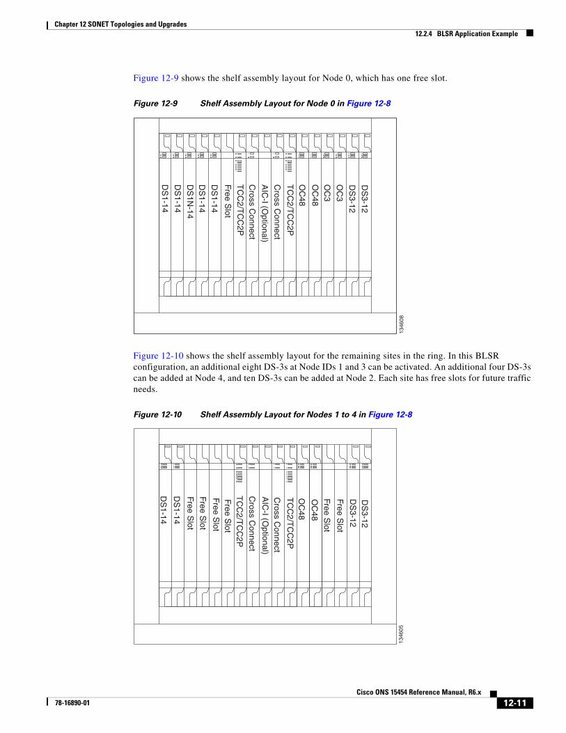
Figure 12-9 shows the shelf assembly layout for Node 0, which has one free slot.
Figure 12-9 Shelf Assembly Layout for Node 0 in Figure 12-8
Figure 12-10 shows the shelf assembly layout for the remaining sites in the ring. In this BLSR configuration, an additional eight DS-3s at Node IDs 1 and 3 can be activated. An additional four DS-3s can be added at Node 4, and ten DS-3s can be added at Node 2. Each site has free slots for future traffic needs.
Figure 12-10 Shelf Assembly Layout for Nodes 1 to 4 in Figure 12-8
DS
1-14
DS
1-14
DS
1N-14
DS
1-14
DS
1-14
OC
48
TC
C2/T
CC
2PC
ross Connect
AIC
-I (Optional)
Cross C
onnect
TC
C2/T
CC
2PO
C48
OC
3
OC
3
DS
3-12
DS
3-12
Free Slot
1346
08D
S1-14
DS
1-14
TC
C2/T
CC
2P
Cross C
onnect
AIC
-I (Optional)
Cross C
onnect
TC
C2/T
CC
2P
Free Slot
Free Slot
OC
48
DS
3-12D
S3-12
Free Slot
Free Slot
Free Slot
OC
48
Free Slot
1346
05
12-11Cisco ONS 15454 Reference Manual, R6.x
78-16890-01

Chapter 12 SONET Topologies and Upgrades12.2.5 BLSR Fiber Connections
12.2.5 BLSR Fiber ConnectionsPlan your fiber connections and use the same plan for all BLSR nodes. For example, make the east port the farthest slot to the right and the west port the farthest slot to the left. Plug fiber connected to an east port at one node into the west port on an adjacent node. Figure 12-11 shows fiber connections for a two-fiber BLSR with trunk cards in Slot 5 (west) and Slot 12 (east). Refer to the Cisco ONS 15454 Procedure Guide for fiber connection procedures.
Note Always plug the transmit (Tx) connector of an OC-N card at one node into the receive (Rx) connector of an OC-N card at the adjacent node. Cards display an SF LED when Tx and Rx connections are mismatched.
Figure 12-11 Connecting Fiber to a Four-Node, Two-Fiber BLSR
For four-fiber BLSRs, use the same east-west connection pattern for the working and protect fibers. Do not mix working and protect card connections. The BLSR does not function if working and protect cards are interconnected. Figure 12-12 shows fiber connections for a four-fiber BLSR. Slot 5 (west) and Slot 12 (east) carry the working traffic. Slot 6 (west) and Slot 13 (east) carry the protect traffic.
5529
7
Node 1
West East
West East
West East
West East
Slot 5
TxRx
Slot 12
TxRx
Node 4
Slot 5
TxRx
Slot 12
TxRx
Node 2
Slot 5
TxRx
Slot 12
TxRx
Node 3
Slot 5
TxRx
Slot 12
TxRx
12-12Cisco ONS 15454 Reference Manual, R6.x
78-16890-01

Chapter 12 SONET Topologies and Upgrades12.3 Unidirectional Path Switched Rings
Figure 12-12 Connecting Fiber to a Four-Node, Four-Fiber BLSR
12.3 Unidirectional Path Switched RingsUPSRs provide duplicate fiber paths around the ring. Working traffic flows in one direction and protection traffic flows in the opposite direction. If a problem occurs with the working traffic path, the receiving node switches to the path coming from the opposite direction.
CTC automates ring configuration. UPSR traffic is defined within the ONS 15454 on a circuit-by-circuit basis. If a path-protected circuit is not defined within a 1+1 or BLSR line protection scheme and path protection is available and specified, CTC uses UPSR as the default.
A UPSR circuit requires two DCC-provisioned optical spans per node. UPSR circuits can be created across these spans until their bandwidth is consumed.
Note If a UPSR circuit is created manually by TL1, data communications channels (DCCs) are not needed; therefore, UPSR circuits are limited by the cross-connection bandwidth or the span bandwidth, but not by the number of DCCs.
The span bandwidth consumed by a UPSR circuit is two times the circuit bandwidth, because the circuit is duplicated. The cross-connection bandwidth consumed by a UPSR circuit is three times the circuit bandwidth at the source and destination nodes only. The cross-connection bandwidth consumed by an intermediate node has a factor of one.
6195
8
Node 1
West East
West East
West East
West East
Slot5
Slot12
Node 4
Slot5
Slot12
Node 2
Slot5
Slot12
Node 3
Slot5
Slot12
TxRx
Slot6
Slot13
TxRx
Slot6
Slot13
TxRx
Slot6
Slot13
TxRx
Slot6
Slot13
Working fibersProtect fibers
12-13Cisco ONS 15454 Reference Manual, R6.x
78-16890-01
Chapter 12 SONET Topologies and Upgrades12.3 Unidirectional Path Switched Rings
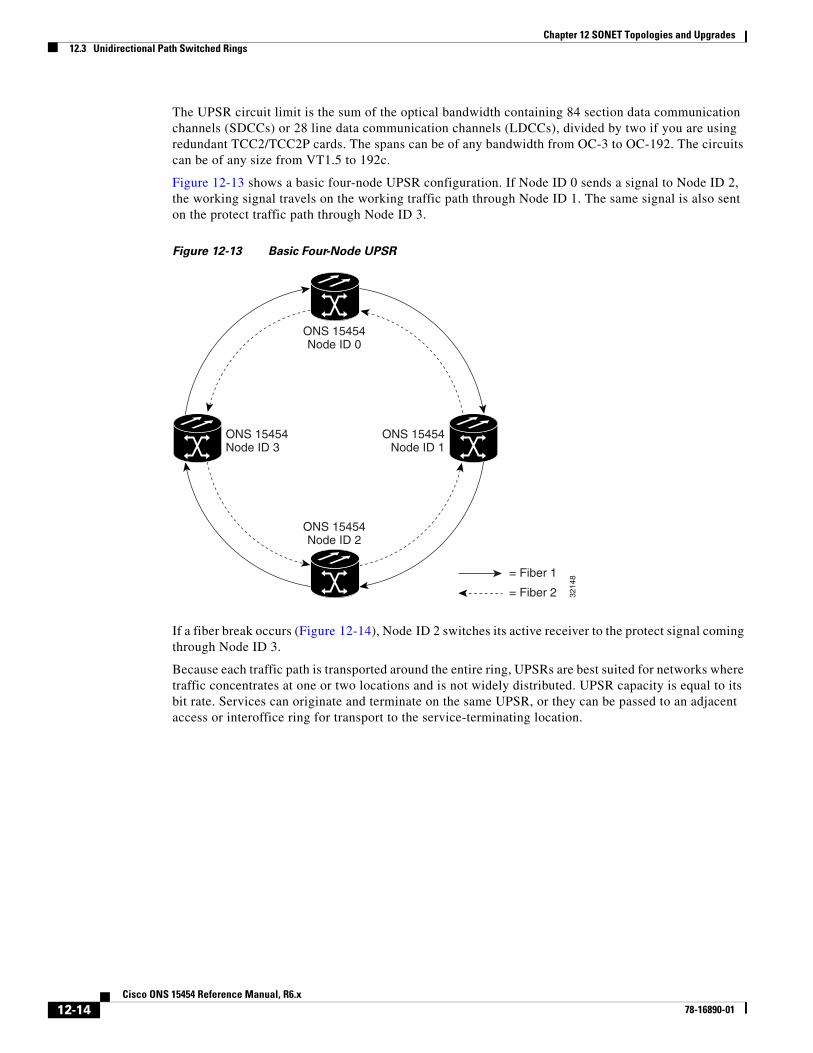
The UPSR circuit limit is the sum of the optical bandwidth containing 84 section data communication channels (SDCCs) or 28 line data communication channels (LDCCs), divided by two if you are using redundant TCC2/TCC2P cards. The spans can be of any bandwidth from OC-3 to OC-192. The circuits can be of any size from VT1.5 to 192c.
Figure 12-13 shows a basic four-node UPSR configuration. If Node ID 0 sends a signal to Node ID 2, the working signal travels on the working traffic path through Node ID 1. The same signal is also sent on the protect traffic path through Node ID 3.
Figure 12-13 Basic Four-Node UPSR
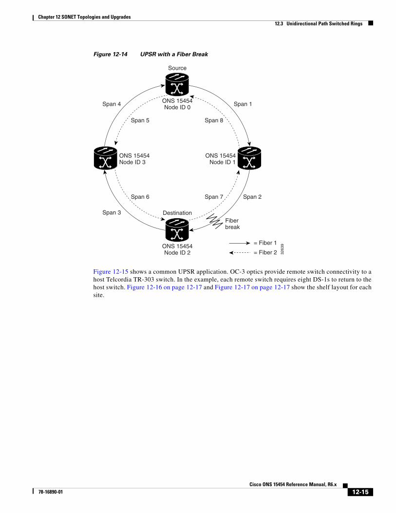
If a fiber break occurs (Figure 12-14), Node ID 2 switches its active receiver to the protect signal coming through Node ID 3.
Because each traffic path is transported around the entire ring, UPSRs are best suited for networks where traffic concentrates at one or two locations and is not widely distributed. UPSR capacity is equal to its bit rate. Services can originate and terminate on the same UPSR, or they can be passed to an adjacent access or interoffice ring for transport to the service-terminating location.
ONS 15454Node ID 0
ONS 15454Node ID 1
ONS 15454Node ID 2
ONS 15454Node ID 3
3214
8= Fiber 1
= Fiber 2
12-14Cisco ONS 15454 Reference Manual, R6.x
78-16890-01
Chapter 12 SONET Topologies and Upgrades12.3 Unidirectional Path Switched Rings
Figure 12-14 UPSR with a Fiber Break
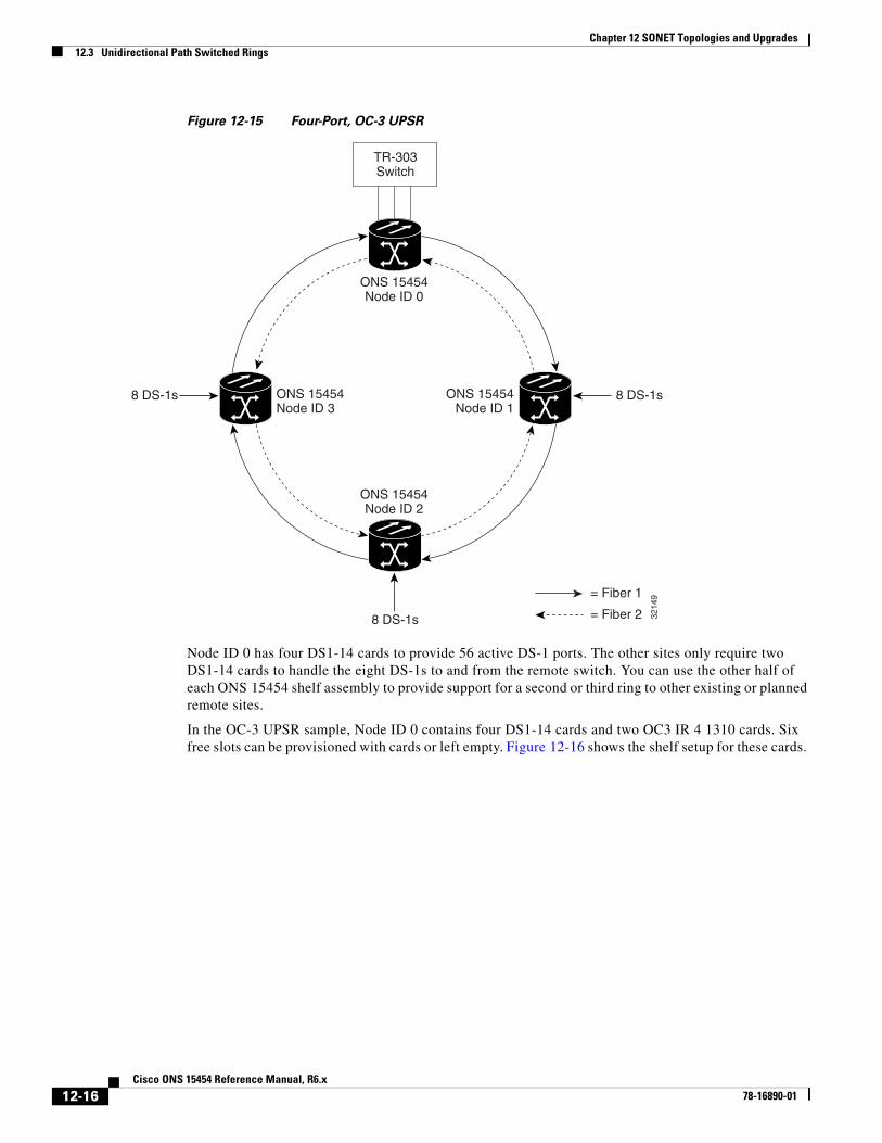
Figure 12-15 shows a common UPSR application. OC-3 optics provide remote switch connectivity to a host Telcordia TR-303 switch. In the example, each remote switch requires eight DS-1s to return to the host switch. Figure 12-16 on page 12-17 and Figure 12-17 on page 12-17 show the shelf layout for each site.
Span 1
Span 2
Span 3
Span 4
Span 8
Span 7Span 6
Span 5
Fiberbreak
Source
Destination
3263
9
ONS 15454Node ID 0
ONS 15454Node ID 1
ONS 15454Node ID 2
ONS 15454Node ID 3
= Fiber 1
= Fiber 2
12-15Cisco ONS 15454 Reference Manual, R6.x
78-16890-01
Chapter 12 SONET Topologies and Upgrades12.3 Unidirectional Path Switched Rings
Figure 12-15 Four-Port, OC-3 UPSR
Node ID 0 has four DS1-14 cards to provide 56 active DS-1 ports. The other sites only require two DS1-14 cards to handle the eight DS-1s to and from the remote switch. You can use the other half of each ONS 15454 shelf assembly to provide support for a second or third ring to other existing or planned remote sites.
In the OC-3 UPSR sample, Node ID 0 contains four DS1-14 cards and two OC3 IR 4 1310 cards. Six free slots can be provisioned with cards or left empty. Figure 12-16 shows the shelf setup for these cards.
8 DS-1s
8 DS-1s
8 DS-1s
TR-303Switch
3214
9
ONS 15454Node ID 0
ONS 15454Node ID 1
ONS 15454Node ID 2
ONS 15454Node ID 3
= Fiber 1
= Fiber 2
12-16Cisco ONS 15454 Reference Manual, R6.x
78-16890-01

Chapter 12 SONET Topologies and Upgrades12.3 Unidirectional Path Switched Rings
Figure 12-16 Layout of Node ID 0 in the OC-3 UPSR Example in Figure 12-15
In the Figure 12-15 on page 12-16 example, Nodes IDs 1 to 3 each contain two DS1-14 cards and two OC3 IR 4 1310 cards. Eight free slots exist. They can be provisioned with other cards or left empty. Figure 12-17 shows the shelf assembly setup for this configuration example.
Figure 12-17 Layout of Node IDs 1 to 3 in the OC-3 UPSR Example in Figure 12-15
DS
1-14
DS
1-14
TC
C2/T
CC
2P
Cross C
onnect
AIC
-I (Optional)
Cross C
onnect
TC
C2/T
CC
2P
Free Slot
OC
3 IR 4 1310
Free Slot
Free Slot
OC
3 IR 4 1310
Free Slot
Free Slot
Free Slot
DS
1-14
DS
1-14
1346
06D
S1-14
DS
1-14
TC
C2/T
CC
2P
Cross C
onnect
AIC
-I (Optional)
Cross C
onnect
TC
C2/T
CC
2P
Free Slot
OC
3 IR 4 1310
Free Slot
Free Slot
OC
3 IR 4 1310
Free Slot
Free Slot
Free Slot
Free Slot
Free Slot
1346
07
12-17Cisco ONS 15454 Reference Manual, R6.x
78-16890-01

Chapter 12 SONET Topologies and Upgrades12.4 Dual-Ring Interconnect
12.4 Dual-Ring InterconnectDual-ring interconnect (DRI) topologies provide an extra level of path protection for circuits on interconnected rings. DRI allows users to interconnect BLSRs, UPSRs, or a UPSR with a BLSR, with additional protection provided at the transition nodes. In a DRI topology, ring interconnections occur at two or four nodes.
The drop-and-continue DRI method is used for all ONS 15454 DRIs. In drop-and-continue DRI, a primary node drops the traffic to the connected ring and routes traffic to a secondary node within the same ring. The secondary node also routes the traffic to the connected ring; that is, the traffic is dropped at two different interconnection nodes to eliminate single points of failure. To route circuits on DRI, you must choose the Dual Ring Interconnect option during circuit provisioning. Dual transmit is not supported.
Two DRI topologies can be implemented on the ONS 15454:
• A traditional DRI requires two pairs of nodes to interconnect two networks. Each pair of user-defined primary and secondary nodes drops traffic over a pair of interconnection links to the other network.
• An integrated DRI requires one pair of nodes to interconnect two networks. The two interconnected nodes replace the interconnection ring.
For DRI topologies, a hold-off timer sets the amount of time before a selector switch occurs. It reduces the likelihood of multiple switches, such as:
• Both a service selector and a path selector
• Both a line switch and a path switch of a service selector
For example, if a UPSR DRI service selector switch does not restore traffic, then the path selector switches after the hold-off time. The UPSR DRI hold-off timer default is 100 ms. You can change this setting in the UPSR Selectors tab of the Edit Circuits window. For BLSR DRI, if line switching does not restore traffic, then the service selector switches. The hold-off time delays the recovery provided by the service selector. The BLSR DRI default hold-off time is 100 ms and cannot be changed.
12.4.1 BLSR DRIUnlike BLSR automatic protection switching (APS) protocol, BLSR-DRI is a path-level protection protocol at the circuit level. Drop-and-continue BLSR-DRI requires a service selector in the primary node for each circuit routing to the other ring. Service selectors monitor signal conditions from dual feed sources and select the one that has the best signal quality. Same-side routing drops the traffic at primary nodes set up on the same side of the connected rings, and opposite-side routing drops the traffic at primary nodes set up on the opposite sides of the connected rings. For BLSR-DRI, primary and secondary nodes cannot be the circuit source or destination.
Note A DRI circuit cannot be created if an intermediate node exists on the interconnecting link. However, an intermediate node can be added on the interconnecting link after the DRI circuit is created.
DRI protection circuits act as protection channel access (PCA) circuits. In CTC, you set up DRI protection circuits by selecting the PCA option when setting up primary and secondary nodes during DRI circuit creation.
12-18Cisco ONS 15454 Reference Manual, R6.x
78-16890-01

Chapter 12 SONET Topologies and Upgrades12.4.1 BLSR DRI
Figure 12-18 shows ONS 15454s in a traditional BLSR-DRI topology with same-side routing. In Ring 1, Nodes 3 and 4 are the interconnect nodes, and in Ring 2, Nodes 8 and 9 are the interconnect nodes. Duplicate signals are sent between Node 4 (Ring 1) and Node 9 (Ring 2), and between Node 3 (Ring 1) and Node 8 (Ring 2). The primary nodes (Nodes 4 and 9) are on the same side, and the secondary nodes (Nodes 3 and 8) provide an alternative route. In Ring 1, traffic at Node 4 is dropped (to Node 9) and continued (to Node 3). Similarly, at Node 9, traffic is dropped (to Node 4) and continued (to Node 8).
Figure 12-18 ONS 15454 Traditional BLSR Dual-Ring Interconnect (Same-Side Routing)
Service Selector
Secondary Path
Primary Path, Drop and Continue to Bridge
Drop and Continue
1152
35
BLSRRing 1
PrimaryNode
SecondaryNode
Node 5
Node 4 Node 3
Node 9 Node 8
Node 1
Node 2
BLSRRing 2
PrimaryNode
SecondaryNode
Node 10
Node 6
Node 7
12-19Cisco ONS 15454 Reference Manual, R6.x
78-16890-01
Chapter 12 SONET Topologies and Upgrades12.4.1 BLSR DRI
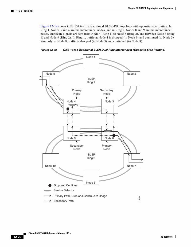
Figure 12-19 shows ONS 15454s in a traditional BLSR-DRI topology with opposite-side routing. In Ring 1, Nodes 3 and 4 are the interconnect nodes, and in Ring 2, Nodes 8 and 9 are the interconnect nodes. Duplicate signals are sent from Node 4 (Ring 1) to Node 8 (Ring 2), and between Node 3 (Ring 1) and Node 9 (Ring 2). In Ring 1, traffic at Node 4 is dropped (to Node 9) and continued (to Node 3). Similarly, at Node 8, traffic is dropped (to Node 3) and continued (to Node 8).
Figure 12-19 ONS 15454 Traditional BLSR Dual-Ring Interconnect (Opposite-Side Routing)
Service Selector
Secondary Path
Primary Path, Drop and Continue to Bridge
Drop and Continue
1152
34
BLSRRing 1
PrimaryNode
SecondaryNode
Node 5
Node 4 Node 3
Node 9 Node 8
Node 1
Node 2
BLSRRing 2
SecondaryNode
PrimaryNode
Node 10
Node 6
Node 7
12-20Cisco ONS 15454 Reference Manual, R6.x
78-16890-01
Chapter 12 SONET Topologies and Upgrades12.4.2 UPSR DRI
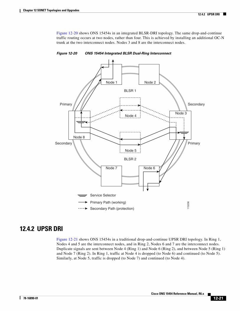
Figure 12-20 shows ONS 15454s in an integrated BLSR-DRI topology. The same drop-and-continue traffic routing occurs at two nodes, rather than four. This is achieved by installing an additional OC-N trunk at the two interconnect nodes. Nodes 3 and 8 are the interconnect nodes.
Figure 12-20 ONS 15454 Integrated BLSR Dual-Ring Interconnect
12.4.2 UPSR DRIFigure 12-21 shows ONS 15454s in a traditional drop-and-continue UPSR DRI topology. In Ring 1, Nodes 4 and 5 are the interconnect nodes, and in Ring 2, Nodes 6 and 7 are the interconnect nodes. Duplicate signals are sent between Node 4 (Ring 1) and Node 6 (Ring 2), and between Node 5 (Ring 1) and Node 7 (Ring 2). In Ring 1, traffic at Node 4 is dropped (to Node 6) and continued (to Node 5). Similarly, at Node 5, traffic is dropped (to Node 7) and continued (to Node 4).
Service Selector
Secondary Path (protection)
Primary Path (working)
1152
36
BLSR 1
Primary
Secondary
Secondary
Primary
BLSR 2
Node 8
Node 3
Node 1 Node 2
Node 6Node 7
Node 5
Node 4
12-21Cisco ONS 15454 Reference Manual, R6.x
78-16890-01

Chapter 12 SONET Topologies and Upgrades12.4.2 UPSR DRI
Figure 12-21 ONS 15454 Traditional UPSR Dual-Ring Interconnect
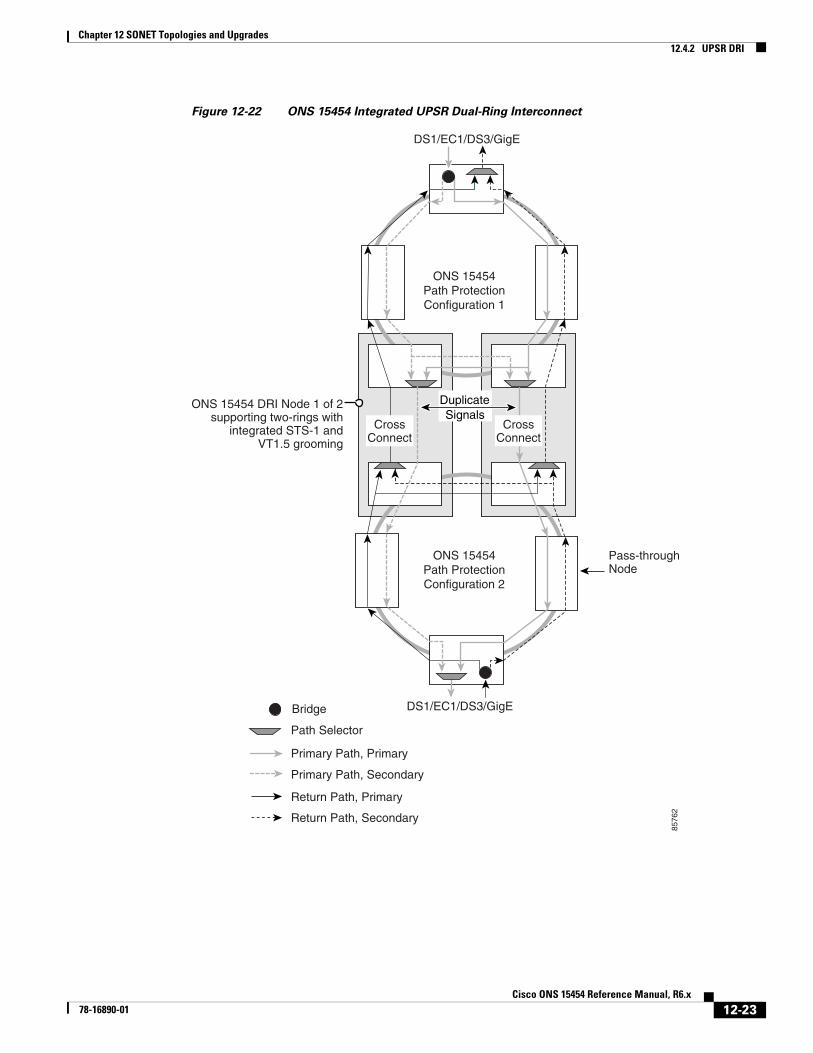
Figure 12-22 shows ONS 15454s in an integrated DRI topology. The same drop-and-continue traffic routing occurs at two nodes, rather than four. This is achieved by installing an additional OC-N trunk at the two interconnect nodes.
Path Selector
Primary Path, Primary
Return Path, Secondary
Return Path, Primary
Primary Path, Secondary
UPSR
Ring 1
DuplicateSignals
Pass-throughNode
UPSR
Ring 2
Bridge
8576
1
Node 1
Node 2Node 3
Node 5Node 4
Node 7Node 6
12-22Cisco ONS 15454 Reference Manual, R6.x
78-16890-01
Chapter 12 SONET Topologies and Upgrades12.4.2 UPSR DRI
Figure 12-22 ONS 15454 Integrated UPSR Dual-Ring Interconnect
Path Selector
Primary Path, Primary
Return Path, Secondary
Return Path, Primary
Primary Path, Secondary
ONS 15454Path ProtectionConfiguration 1
ONS 15454Path ProtectionConfiguration 2
DS1/EC1/DS3/GigE
DuplicateSignals
Pass-throughNode
DS1/EC1/DS3/GigEBridge
8576
2
CrossConnect
CrossConnect
ONS 15454 DRI Node 1 of 2supporting two-rings with
integrated STS-1 andVT1.5 grooming
12-23Cisco ONS 15454 Reference Manual, R6.x
78-16890-01
Chapter 12 SONET Topologies and Upgrades12.4.3 UPSR/BLSR DRI Handoff Configurations
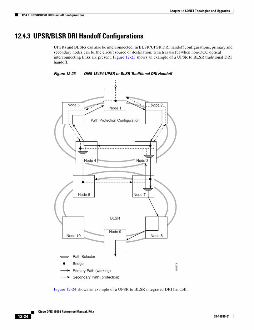
12.4.3 UPSR/BLSR DRI Handoff ConfigurationsUPSRs and BLSRs can also be interconnected. In BLSR/UPSR DRI handoff configurations, primary and secondary nodes can be the circuit source or destination, which is useful when non-DCC optical interconnecting links are present. Figure 12-23 shows an example of a UPSR to BLSR traditional DRI handoff.
Figure 12-23 ONS 15454 UPSR to BLSR Traditional DRI Handoff
Figure 12-24 shows an example of a UPSR to BLSR integrated DRI handoff.
Path Selector
Secondary Path (protection)
Primary Path (working)
Bridge
1152
73
Path Protection Configuration
BLSR
Node 1Node 5 Node 2
Node 10
Node 6 Node 7
Node 4 Node 3
Node 8Node 9
12-24Cisco ONS 15454 Reference Manual, R6.x
78-16890-01

Chapter 12 SONET Topologies and Upgrades12.5 Comparison of the Protection Schemes
Figure 12-24 ONS 15454 UPSR to BLSR Integrated DRI Handoff
12.5 Comparison of the Protection SchemesTable 12-4 shows a comparison of the different protection schemes using OC-48 as an example.
Path Selector
Bridge
1152
72
Path Protection Configuration
BLSR
Node 4 Node 3
Node 1Node 5 Node 2
Node 8 Node 6Node 7
12-25Cisco ONS 15454 Reference Manual, R6.x
78-16890-01

Chapter 12 SONET Topologies and Upgrades12.6 Subtending Rings
12.6 Subtending RingsThe ONS 15454 supports up to 84 SONET SDCCs or 28 SONET LDCCs with TCC2/TCC2P cards. See Table 12-1 on page 12-1 for ring, SDCC, and LDCC information.
Subtending rings reduce the number of nodes and cards required, and reduce external shelf-to-shelf cabling. Figure 12-25 shows an ONS 15454 with multiple subtending rings.
Table 12-4 Comparison of the Protection Schemes
Topology Ring Capacity
Protected Bandwidth Between Any Two Nodes
Protection Channel Access
Dual Failure Number of Cards
Path Protection 48 - PT STS 1-48 Not supported
Not supported
2 x N
Two-Fiber BLSR 24 x N1 - PT2
STS 1-24 STS 25-48 Not supported
2 x N
Four-Fiber BLSR 48 x N - PT STS 1-48 (Fiber 1)
STS 1-48 (Fiber 2)
Supported 4 x N
Two-Fiber BLSR DRI 24 x N - PT STS 1-24 STS 25-48 Supported (2 x N) + 4
Path Protection DRI 48 - PT STS 1-48 Not supported
Supported (2 x N) + 4
1. N equals the number of ONS 15454 nodes configured as BLSR nodes.
2. PT equals the number of STS-1 circuits passed through ONS 15454 nodes in the ring (capacity can vary depending on the traffic pattern).
12-26Cisco ONS 15454 Reference Manual, R6.x
78-16890-01

Chapter 12 SONET Topologies and Upgrades12.6 Subtending Rings
Figure 12-25 ONS 15454 with Multiple Subtending Rings
Figure 12-26 shows a UPSR subtending from a BLSR. In this example, Node 3 is the only node serving both the BLSR and UPSR. OC-N cards in Slots 5 and 12 serve the BLSR, and OC-N cards in Slots 6 and 13 serve the UPSR.
Figure 12-26 UPSR Subtending from a BLSR
The ONS 15454 can support two BLSRs on the same node. This allows you to deploy an ONS 15454 in applications requiring SONET Digital Cross-connect Systems (DCSs) or multiple SONET add/drop multiplexers (ADMs).
PathProtected
Nodes
BLSR
BLSR55
302
Node 3
Node 1
Node 2
BLSR
Node 455
303
Slot 13
Slot 12
Slot 12
Slot 12
Slot 13
Slot 6 Slot 5
Slot 5
Slot 5Slot 6
12-27Cisco ONS 15454 Reference Manual, R6.x
78-16890-01

Chapter 12 SONET Topologies and Upgrades12.7 Linear ADM Configurations
Figure 12-27 shows two BLSRs shared by one ONS 15454. Ring 1 runs on Nodes 1, 2, 3, and 4. Ring 2 runs on Nodes 4, 5, 6, and 7. Two BLSR rings, Ring 1 and Ring 2, are provisioned on Node 4. Ring 1 uses cards in Slots 5 and 12, and Ring 2 uses cards in Slots 6 and 13.
Note Nodes in different BLSRs can have the same, or different node IDs.
Figure 12-27 BLSR Subtending from a BLSR
After subtending two BLSRs, you can route circuits from nodes in one ring to nodes in the second ring. For example, in Figure 12-27 you can route a circuit from Node 1 to Node 7. The circuit would normally travel from Node 1 to Node 4 to Node 7. If fiber breaks occur, for example between Nodes 1 and 4 and Nodes 4 and 7, traffic is rerouted around each ring: in this example, Nodes 2 and 3 in Ring 1 and Nodes 5 and 6 in Ring 2.
12.7 Linear ADM ConfigurationsYou can configure ONS 15454s as a line of add/drop multiplexers (ADMs) by configuring one set of OC-N cards as the working path and a second set as the protect path. Unlike rings, point-to-point ADMs (two-node configurations) and linear ADMs (three-node configurations) require that the OC-N cards at each node be in 1+1 protection to ensure that a break to the working line is automatically routed to the protect line.
Figure 12-28 shows three ONS 15454s in a linear ADM configuration. Working traffic flows from Slot 5/Node 1 to Slot 5/Node 2, and from Slot 12/Node 2 to Slot 12/Node 3. You create the protect path by placing Slot 6 in 1+1 protection with Slot 5 at Nodes 1 and 2, and Slot 12 in 1+1 protection with Slot 13 at Nodes 2 and 3.
5529
8
Node 5
Slot 6West
EastSlot 13
Node 7
Slot 13East
Slot 6West
Slot 6West
Slot 13East
Node 6
Node 1
Slot 5West
Slot 5West
Slot 12East
Slot 12East
Node 3
Slot 12East
Slot 5West
Node 2
Slot 5West
Slot 12East
Slot 13East
Slot 6West
Node 4
BLSRRing 1
BLSRRing 2
12-28Cisco ONS 15454 Reference Manual, R6.x
78-16890-01
Chapter 12 SONET Topologies and Upgrades12.8 Path-Protected Mesh Networks
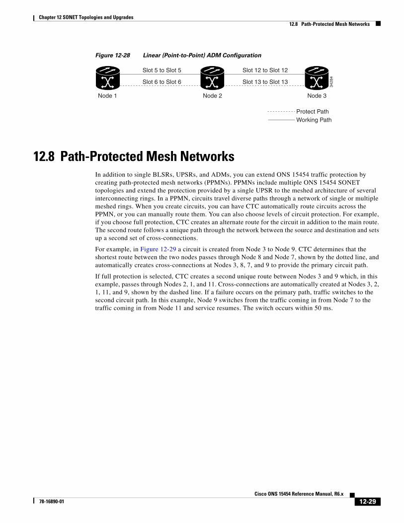
Figure 12-28 Linear (Point-to-Point) ADM Configuration
12.8 Path-Protected Mesh NetworksIn addition to single BLSRs, UPSRs, and ADMs, you can extend ONS 15454 traffic protection by creating path-protected mesh networks (PPMNs). PPMNs include multiple ONS 15454 SONET topologies and extend the protection provided by a single UPSR to the meshed architecture of several interconnecting rings. In a PPMN, circuits travel diverse paths through a network of single or multiple meshed rings. When you create circuits, you can have CTC automatically route circuits across the PPMN, or you can manually route them. You can also choose levels of circuit protection. For example, if you choose full protection, CTC creates an alternate route for the circuit in addition to the main route. The second route follows a unique path through the network between the source and destination and sets up a second set of cross-connections.
For example, in Figure 12-29 a circuit is created from Node 3 to Node 9. CTC determines that the shortest route between the two nodes passes through Node 8 and Node 7, shown by the dotted line, and automatically creates cross-connections at Nodes 3, 8, 7, and 9 to provide the primary circuit path.
If full protection is selected, CTC creates a second unique route between Nodes 3 and 9 which, in this example, passes through Nodes 2, 1, and 11. Cross-connections are automatically created at Nodes 3, 2, 1, 11, and 9, shown by the dashed line. If a failure occurs on the primary path, traffic switches to the second circuit path. In this example, Node 9 switches from the traffic coming in from Node 7 to the traffic coming in from Node 11 and service resumes. The switch occurs within 50 ms.
Node 1 Node 3Node 2
Slot 5 to Slot 5
Slot 6 to Slot 6
Slot 12 to Slot 12
Slot 13 to Slot 13
Working PathProtect Path
3428
4
12-29Cisco ONS 15454 Reference Manual, R6.x
78-16890-01

Chapter 12 SONET Topologies and Upgrades12.8 Path-Protected Mesh Networks
Figure 12-29 Path-Protected Mesh Network
PPMN also allows spans with different SONET speeds to be mixed together in “virtual rings.” Figure 12-30 shows Nodes 1, 2, 3, and 4 in a standard OC-48 ring. Nodes 5, 6, 7, and 8 link to the backbone ring through OC-12 fiber. The “virtual ring” formed by Nodes 5, 6, 7, and 8 uses both OC-48 and OC-12 cards.
= Primary path= Secondary path
Working trafficProtect traffic
Source Node
DestinationNode
3213
6
Node 1
Node 11
Node 2
Node 4
Node 5
Node 6
Node 7
Node 8Node 10
Node 9
Node 3
12-30Cisco ONS 15454 Reference Manual, R6.x
78-16890-01

Chapter 12 SONET Topologies and Upgrades12.9 Four-Shelf Node Configurations
Figure 12-30 PPMN Virtual Ring
12.9 Four-Shelf Node ConfigurationsYou can link multiple ONS 15454s using their OC-N cards (that is, create a fiber-optic bus) to accommodate more access traffic than a single ONS 15454 can support. Refer to the Cisco ONS 15454 Procedure Guide. For example, to drop more than 112 DS-1s or 96 DS-3s (the maximum that can be aggregated in a single node), you can link the nodes but not merge multiple nodes into a single ONS 15454. You can link nodes with OC-12 or OC-48 fiber spans as you would link any other two network nodes. The nodes can be grouped in one facility to aggregate more local traffic.
Figure 12-31 on page 12-32 shows a four-shelf node setup. Each shelf assembly is recognized as a separate node in the ONS 15454 software interface and traffic is mapped using CTC cross-connect options. In Figure 12-31, each node uses redundant fiber-optic cards. Node 1 uses redundant OC-N transport and OC-N bus (connecting) cards for a total of four cards, with eight free slots remaining. Nodes 2 and 3 each use two redundant OC-N bus cards for a total of four cards, with eight free slots remaining. Node 4 uses redundant OC-12 bus cards for a total of two cards, with ten free slots remaining. The four-shelf node example presented here is one of many ways to set up a multiple-node configuration.
OC-48 OC-12OC-12
3213
7
ONS 15454Node 5
ONS 15454Node 1
ONS 15454Node 6
ONS 15454Node 2
ONS 15454Node 4
ONS 15454Node 8
ONS 15454Node 3
ONS 15454Node 7
12-31Cisco ONS 15454 Reference Manual, R6.x
78-16890-01

Chapter 12 SONET Topologies and Upgrades12.10 OC-N Speed Upgrades
Figure 12-31 Four-Shelf Node Configuration
12.10 OC-N Speed UpgradesA span is the optical fiber connection between two ONS 15454 nodes. In a span (optical speed) upgrade, the transmission rate of a span is upgraded from a lower to a higher OC-N signal but all other span configuration attributes remain unchanged. With multiple nodes, a span upgrade is a coordinated series of upgrades on all nodes in the ring or protection group. You can perform in-service span upgrades for the following ONS 15454 cards:
• Single-port OC-12 to OC-48
• Single-port OC-12 to OC-192
• Single-port OC-12 to four-port OC-12
• Single-port OC-12 to MRC-12
• OC-48 to OC-192
• OC-48 to OC192SR1/STM64IO Short Reach or OC192/STM64 Any Reach
You can also perform in-service card upgrades for the following ONS 15454 cards:
• Four-port OC-3 to eight-port OC-3
• Single-port OC-12 to four-port OC-12
• Single-port OC-12 to OC-48
• Single-port OC-12 to OC-192
• Single-port OC-12 to MRC-12
• OC-48 to MRC-12
• OC-192 to OC192-XFP
Redundant OC-N Bus
OC-N Feed
Redundant OC-N Bus
Redundant OC-N Bus
Up to 72 DS-3s, 84 DS-1s
Up to 72 DS-3s, 84 DS-1s
ONS 15454, Node 1
ONS 15454, Node 2
ONS 15454, Node 3
ONS 15454, Node 4
Redundant
Up to 72 DS-3s, 84 DS-1s
Up to 96 DS-3s, 112 DS-1s
32097
12-32Cisco ONS 15454 Reference Manual, R6.x
78-16890-01

Chapter 12 SONET Topologies and Upgrades12.10 OC-N Speed Upgrades
• OC-48 to OC192SR1/STM64IO Short Reach or OC192/STM64 Any Reach
Table 12-5 lists permitted upgrades for Slots 5, 6, 12, and 13 (high-speed slots).
Table 12-6 lists permitted upgrades for Slots 1 through 4 and 14 through 17 (low-speed slots).
Table 12-5 Slot 5, 6, 12, and 13 Upgrade Options
CardsFour-port OC-3
Eight-port OC-3
One-port OC-12
Four-port OC-12 OC-48 OC-192 MRC-12
Four-port OC-3 — Not supported
Not supported
Not supported
Not supported
Not supported
Not supported
Eight-port OC-31
1. The eight-port OC-3 is not supported in Slots 5, 6, 12, and 13.
Not supported
— Not supported
Not supported
Not supported
Not supported
Not supported
One-port OC-12 Not supported
Not supported
— Not supported
Supported Supported Supported
Four-port OC-122
2. The four-port OC-12 is not supported in Slots 5, 6, 12, and 13.
Not supported
Not supported
Not supported
— Not supported
Not supported
Not supported
OC-48 Not supported
Not supported
Supported Not supported
— Supported Supported
OC-192 Not supported
Not supported
Supported Not supported
Supported — Not supported
MRC-12 Not supported
Not supported
Supported Not supported
Supported Not supported
—
Table 12-6 Upgrade Options for Slots 1 through 4 and 14 through 17
CardsFour-port OC-3
Eight-port OC-3
One-port OC-12
Four-port OC-12 OC-48 OC-192 MRC-12
Four-port OC-3 — Supported Not supported
Not supported
Not supported
— Not supported
Eight-port OC-3 Supported — Not supported
Not supported
Not supported
— Not supported
One-port OC-12 Not supported
Not supported
— Supported Supported — Supported
Four-port OC-12 Not supported
Not supported
Supported — Not supported
— Not supported
OC-48 Not supported
Not supported
Supported Not supported
— — Supported
OC-1921
1. The OC-192 is not supported on Slots 1 through 4 and 14 through 17.
— — — — — — Not supported
MRC-12 Not supported
Not supported
Supported Not supported
Supported Not supported
—
12-33Cisco ONS 15454 Reference Manual, R6.x
78-16890-01

Chapter 12 SONET Topologies and Upgrades12.10.1 Span Upgrade Wizard
Note Replacing cards that are the same speed are not considered span upgrades. For example replacing a four-port OC-3 with an eight-port OC-3 card or replacing a single-port OC-12 with a four-port OC-12 card.
To perform a span upgrade, the higher-rate OC-N card must replace the lower-rate card in the same slot. If the upgrade is conducted on spans residing in a BLSR, all spans in the ring must be upgraded. The protection configuration of the original lower-rate OC-N card (two-fiber BLSR, four-fiber BLSR, UPSR, and 1+1) is retained for the higher-rate OC-N card.
To perform a span upgrade on either the OC192-XFP or MRC-12 card with an SFP/XFP (known as pluggable port modules, PPMs, in CTC), the higher-rate PPM must replace the lower-rate PPM in the same slot. If you are using a multi-rate PPM, you do not need to physically replace the PPM but can provision the PPM for a different line rate. All spans in the network must be upgraded. The 1+1 protection configuration of the original lower-rate PPM is retained for the higher-rate PPM.
When performing span upgrades on a large number of nodes, we recommend that you upgrade all spans in a ring consecutively and in the same maintenance window. Until all spans are upgraded, mismatched card types or PPM types are present.
We recommend using the Span Upgrade Wizard to perform span upgrades. Although you can also use the manual span upgrade procedures, the manual procedures are mainly provided as error recovery for the wizard. The Span Upgrade Wizard and the Manual Span Upgrade procedures require at least two technicians (one at each end of the span) who can communicate with each other during the upgrade. Upgrading a span is non-service affecting and causes no more than three switches, each of which is less than 50 ms in duration.
Note Span upgrades do not upgrade SONET topologies (for example, a 1+1 group to a two-fiber BLSR). Refer to the Cisco ONS 15454 Procedure Guide for topology upgrade procedures.
12.10.1 Span Upgrade WizardThe Span Upgrade Wizard automates all steps in the manual span upgrade procedure (BLSR, UPSR, and 1+1). The wizard can upgrade both lines on one side of a four-fiber BLSR or both lines of a 1+1 group; the wizard upgrades UPSRs and two-fiber BLSRs one line at a time. The Span Upgrade Wizard requires that all working spans have DCC enabled.
The Span Upgrade Wizard provides no way to back out of an upgrade. In the case of an error, you must exit the wizard and initiate the manual procedure to either continue with the upgrade or back out of it. To continue with the manual procedure, examine the standing conditions and alarms to identify the stage in which the wizard failure occurred.
12.10.2 Manual Span UpgradesManual span upgrades are mainly provided as error recovery for the Span Upgrade Wizard, but they can be used to perform span upgrades. Downgrading can be performed to back out of a span upgrade. The procedure for downgrading is the same as upgrading except that you choose a lower-rate card type. You cannot downgrade if circuits exist on the STSs that will be removed (the higher STSs).
Procedures for manual span upgrades can be found in the “Upgrade Cards and Spans” chapter in the Cisco ONS 15454 Procedure Guide. Five manual span upgrade options are available:
12-34Cisco ONS 15454 Reference Manual, R6.x
78-16890-01

Chapter 12 SONET Topologies and Upgrades12.11 In-Service Topology Upgrades
• Upgrade on a two-fiber BLSR
• Upgrade on a four-fiber BLSR
• Upgrade on a UPSR
• Upgrade on a 1+1 protection group
• Upgrade on an unprotected span
12.11 In-Service Topology UpgradesTopology upgrades can be performed in-service to convert a live network to a different topology. An in-service topology upgrade is potentially service-affecting, and generally allows a traffic hit of 50 ms or less. Traffic might not be protected during the upgrade. The following in-service topology upgrades are supported:
• Unprotected point-to-point or linear ADM to UPSR
• Point-to-point or linear ADM to two-fiber BLSR
• UPSR to two-fiber BLSR
• Two-fiber to four-fiber BLSR
• Node addition or removal from an existing topology
You can perform in-service topology upgrades irrespective of the service state of the involved cross-connects or circuits; however, a circuit must have a DISCOVERED status.
Circuit types supported for in-service topology upgrades are:
• STS, VT, and VT tunnels
• Virtual concatenated circuits (VCAT)
• Unidirectional and bidirectional
• Automatically routed and manually routed
• CTC-created and TL1-created
• Ethernet (unstitched)
• Multiple source and destination (both sources should be on one node and both drops on one node)
You cannot upgrade stitched Ethernet circuits during topology conversions. For in-service topology upgrade procedures, refer to the “Convert Network Configurations” chapter in the Cisco ONS 15454 Procedure Guide. For procedures to add or remove a node, refer to the “Add and Remove Nodes” chapter of the Cisco ONS 15454 Procedure Guide.
Note A database restore on all nodes in a topology returns converted circuits to their original topology.
Note Open-ended UPSR and DRI configurations do not support in-service topology upgrades.
12-35Cisco ONS 15454 Reference Manual, R6.x
78-16890-01

Chapter 12 SONET Topologies and Upgrades12.11.1 Unprotected Point-to-Point or Linear ADM to UPSR
12.11.1 Unprotected Point-to-Point or Linear ADM to UPSRCTC provides a topology conversion wizard for converting an unprotected point-to-point or linear ADM topology to UPSR. This conversion occurs at the circuit level. CTC calculates the additional UPSR circuit route automatically or you can do it manually. When routing the UPSR circuit, you can provision the USPR as go-and-return or unidirectional.
When performing an in-service topology upgrade on a configuration with VCAT circuits, CTC allows you to select member circuits to upgrade individually. When upgrading VT tunnels, CTC does not convert the VT tunnel to UPSR, but instead creates a secondary tunnel for the alternate path. The result is two unprotected VT tunnels using alternate paths.
To convert from point-to-point or linear ADM to a UPSR, the topology requires an additional circuit route to complete the ring. When the route is established, CTC creates circuit connections on any intermediate nodes and modifies existing circuit connections on the original circuit path. The number and position of network spans in the topology remains unchanged during and after the conversion.
Figure 12-32 shows an unprotected point-to-point ADM configuration converted to a UPSR. An additional circuit routes through Node 3 to complete the UPSR.
Figure 12-32 Unprotected Point-to-Point ADM to UPSR Conversion
12.11.2 Point-to-Point or Linear ADM to Two-Fiber BLSRA 1+1 point-to-point or linear ADM to a two-fiber BLSR conversion is manual. You must remove the protect fibers from all nodes in the linear ADM and route them from the end node to the protect port on the other end node. In addition, you must delete the circuit paths that are located in the bandwidth that will become the protection portion of the two-fiber BLSR (for example, circuits in STS 25 or higher on an OC-48 BLSR) and recreate them in the appropriate bandwidth. Finally, you must provision the nodes as BLSR nodes.
To complete a conversion from an unprotected point-to-point or linear ADM to a two-fiber BLSR, use the CTC Convert Unprotected/UPSR to BLSR wizard from the Tools > Topology Upgrade menu.
OC-48 OC-12
37
ONS 15454Node 1
ONS 15454Node 4
ONS 15454Node 8
12-36Cisco ONS 15454 Reference Manual, R6.x
78-16890-01
Chapter 12 SONET Topologies and Upgrades12.11.3 UPSR to Two-Fiber BLSR
12.11.3 UPSR to Two-Fiber BLSRCTC provides a topology conversion wizard to convert a UPSR to a two-fiber BLSR. An upgrade from a UPSR to a two-fiber BLSR changes path protection to line protection. A UPSR can have a maximum of 16 nodes before conversion. Circuits paths must occupy the same time slots around the ring. Only the primary path through the UPSR is needed; the topology conversion wizard removes the alternate UPSR path during the conversion. Because circuit paths can begin and end outside of the topology, the conversion might create line-protected segments within UPSR paths of circuits outside the scope of the ring. The physical arrangement of the ring nodes and spans remains the same after the conversion.
12.11.4 Two-Fiber BLSR to Four-Fiber BLSR CTC provides a wizard to convert two-fiber OC-48 or OC-192 BLSRs to four-fiber BLSRs. To convert the BLSR, you must install two OC-48 or OC-192 cards at each two-fiber BLSR node, then log into CTC and convert each node from two-fiber to four-fiber. The fibers that were divided into working and protect bandwidths for the two-fiber BLSR are now fully allocated for working BLSR traffic.
12.11.5 Add or Remove a Node from a TopologyYou can add or remove a node from a linear ADM, BLSR, or UPSR configuration. Adding or removing nodes from BLSRs is potentially service affecting; however, adding and removing nodes from an existing 1+1 linear ADM or UPSR configuration does not disrupt traffic. CTC provides a wizard for adding a node to a point-to-point or 1+1 linear ADM. This wizard is used when adding a node between two other nodes.
12-37Cisco ONS 15454 Reference Manual, R6.x
78-16890-01

Chapter 12 SONET Topologies and Upgrades12.11.5 Add or Remove a Node from a Topology
12-38Cisco ONS 15454 Reference Manual, R6.x
78-16890-01