SOLUTION · 2016-04-04 · rin Basic nineerin Circit nalsis 11 1 Chapter 01: Basic Concepts Problem...
52
Irwin, Basic Engineering Circuit Analysis, 11/E 1 Chapter 01: Basic Concepts Problem 1.1 SOLUTION: 1.1 If the current in an electric conductor is 2.4 A, how many coulombs of charge pass any point in a 30-second interval?
Transcript of SOLUTION · 2016-04-04 · rin Basic nineerin Circit nalsis 11 1 Chapter 01: Basic Concepts Problem...

Irwin, Basic Engineering Circuit Analysis, 11/E 1
Chapter 01: Basic Concepts Problem 1.1
SOLUTION:
1.1 If the current in an electric conductor is 2.4 A, how many coulombs of charge pass any point in a 30-second interval?

Irwin, Basic Engineering Circuit Analysis, 11/E 1
Chapter 01: Basic Concepts Problem 1.2
SOLUTION:
1.2 Determine the time interval required for a 12-A battery charger to deliver 4800 C.

Irwin, Basic Engineering Circuit Analysis, 11/E 1
Chapter 01: Basic Concepts Problem 1.3
SOLUTION:
1.3 A lightning bolt carrying 30,000 A lasts for 50 micro-seconds. If the lightning strikes an airplane flying at 20,000 feet, what is the charge deposited on the plane?

Irwin, Basic Engineering Circuit Analysis, 11/E 1
Chapter 01: Basic Concepts Problem 1.4
SOLUTION:
1.4 If a 12-V battery delivers 100 J in 5 s, find (a) the amount of charge delivered and (b) the current produced.

Irwin, Basic Engineering Circuit Analysis, 11/E 1
Chapter 01: Basic Concepts Problem 1.5
SOLUTION:
1.5 The current in a conductor is 1.5 A. How many coulombs of charge pass any point in a time interval of 1.5 minutes?

Irwin, Basic Engineering Circuit Analysis, 11/E 1
Chapter 01: Basic Concepts Problem 1.6
SOLUTION:
1.6 If 60 C of charge pass through an electric conductor in 30 seconds, determine the current in the conductor.

Irwin, Basic Engineering Circuit Analysis, 11/E 1
Chapter 01: Basic Concepts Problem 1.7
SOLUTION:
1.7 Determine the number of coulombs of charge produced by a 12-A battery charger in an hour.

Irwin, Basic Engineering Circuit Analysis, 11/E 1
Chapter 01: Basic Concepts Problem 1.8
SOLUTION:
1.8 Five coulombs of charge pass through the element in Fig. P1.8 from point A to point B. If the energy absorbed by the element is 120 J, determine the voltage across the element.
B
A
+
−
V1
Figure P1.8

Irwin, Basic Engineering Circuit Analysis, 11/E 1
Chapter 01: Basic Concepts Problem 1.9
SOLUTION:
1.9 The current that enters an element is shown in Fig. P1.9. Find the charge that enters the element in the time interval 0 < t < 20 s.
i(t) mA
t (s)0
10
10 20
Figure P1.9

Irwin, Basic Engineering Circuit Analysis, 11/E 1
Chapter 01: Basic Concepts Problem 1.10
SOLUTION:
1.10 The charge entering the positive terminal of an element is q(t) = −30 e −4t mC. If the voltage across the element is 120 e −2t V, determine the energy delivered to the element in the time interval 0 < t < 50 ms.

Irwin, Basic Engineering Circuit Analysis, 11/E 1
Chapter 01: Basic Concepts Problem 1.11
SOLUTION:
1.11 The charge entering the positive terminal of an element is given by the expression q(t) = −12 e−2t mC. The power delivered to the element is p(t) = 2.4 e −3t W. Compute the current in the element, the voltage across the element, and the energy delivered to the element in the time interval 0 < t < 100 ms.

Irwin, Basic Engineering Circuit Analysis, 11/E 1
Chapter 01: Basic Concepts Problem 1.12
SOLUTION:
1.12 The voltage across an element is 12 e −2t V. The current entering the positive terminal of the element is 2 e −2t A. Find the energy absorbed by the element in 1.5 s starting from t = 0.

Irwin, Basic Engineering Circuit Analysis, 11/E 1
Chapter 01: Basic Concepts Problem 1.13
SOLUTION:
1.13 The power absorbed by the BOX in Fig. P1.13 is 2 e −2t W. Calculate the amount of charge that enters the BOX between 0.1 and 0.4 seconds.
4e−t V BOX+−
Figure P1.13

Irwin, Basic Engineering Circuit Analysis, 11/E 1
Chapter 01: Basic Concepts Problem 1.14
SOLUTION:
1.14 The power absorbed by the BOX in Fig. P1.14 is 0.1 e −4t W. Calculate the energy absorbed by the BOX during this same time interval.
10e−2t V BOX+−
Figure P1.14

Irwin, Basic Engineering Circuit Analysis, 11/E 1
Chapter 01: Basic Concepts Problem 1.15
SOLUTION:
1.15 The energy absorbed by the BOX in Fig. P1.15 is shown below. How much charge enters the BOX between 0 and 10 milliseconds?
Figure P1.15
15 V BOX+−
i (t)
w(t) (mJ)
t (ms)
5
10
15
−10
−15
−5
1 2 3 4 5 6 7 8 9 10
15 V BOX+−
i (t)
w(t) (mJ)
t (ms)
5
10
15
−10
−15
−5
1 2 3 4 5 6 7 8 9 10
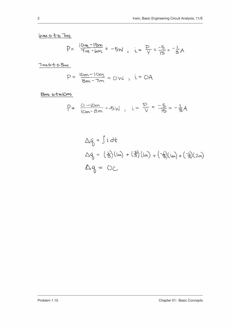
2 Irwin, Basic Engineering Circuit Analysis, 11/E
Problem 1.15 Chapter 01: Basic Concepts

Irwin, Basic Engineering Circuit Analysis, 11/E 1
Chapter 01: Basic Concepts Problem 1.16
SOLUTION:
1.16 The charge that enters the BOX in Fig. P1.16 is shown in the graph below. Calculate and sketch the current flowing into and the power absorbed by the BOX between 0 and 10 milliseconds.
12 V BOX+−
i (t)
q(t) (mC)
t (ms)
1
2
3
−2
−3
−1
1 2 3 4
5
6 7 8 9 10
12 V BOX+−
i (t)
q(t) (mC)
t (ms)
1
2
3
−2
−3
−1
1 2 3 4
5
6 7 8 9 10
Figure P1.16

2 Irwin, Basic Engineering Circuit Analysis, 11/E
Problem 1.16 Chapter 01: Basic Concepts

Irwin, Basic Engineering Circuit Analysis, 11/E 3
Chapter 01: Basic Concepts Problem 1.16

Irwin, Basic Engineering Circuit Analysis, 11/E 1
Chapter 01: Basic Concepts Problem 1.17
SOLUTION:
1.17 The energy absorbed by the BOX in Fig. P1.17 is given below. Calculate and sketch the current flowing into the BOX. Also calculate the charge which enters the BOX between 0 and 12 seconds.
10 V BOX+−
i (t)
w(t) (J)
t (s)
5
−2.5
1 2 3 4 5
6 7 8
9
10
11
12
10 V BOX+−
i (t)
w(t) (J)
t (s)
5
−2.5
1 2 3 4 5
6 7 8
9
10
11
12
Figure P1.17

2 Irwin, Basic Engineering Circuit Analysis, 11/E
Problem 1.17 Chapter 01: Basic Concepts

Irwin, Basic Engineering Circuit Analysis, 11/E 1
Chapter 01: Basic Concepts Problem 1.18
1.18 The charge entering the upper terminal of the BOX in Fig. P1.18 is shown below. How much energy is absorbed by the BOX between 0 and 9 seconds?
12 V BOX+−
i (t)
q(t) (C)
t (s)
0.5
1
−1
−1.5
−0.5
1 2 3 4 5 6 7 8 9
12 V BOX+−
i (t)
q(t) (C)
t (s)
0.5
1
−1
−1.5
−0.5
1 2 3 4 5 6 7 8 9
Figure P1.18
SOLUTION:

2 Irwin, Basic Engineering Circuit Analysis, 11/E
Problem 1.18 Chapter 01: Basic Concepts

Irwin, Basic Engineering Circuit Analysis, 11/E 1
Chapter 01: Basic Concepts Problem 1.19
SOLUTION:
1.19 The energy absorbed by the BOX in Fig. P1.19 is shown in the graph below. Calculate and sketch the current flowing into the BOX between 0 and 10 milliseconds.
12 V BOX+−
i (t)
w(t) (mJ)
t (ms)
10
20
30
−20
−30
−10
1 2 3 4
5 6 7
8 9 10
12 V BOX+−
i (t)
w(t) (mJ)
t (ms)
10
20
30
−20
−30
−10
1 2 3 4
5 6 7
8 9 10
Figure P1.19

2 Irwin, Basic Engineering Circuit Analysis, 11/E
Problem 1.19 Chapter 01: Basic Concepts
Irwin, Basic Engineering Circuit Analysis, 11/E 1
Chapter 01: Basic Concepts Problem 1.20
SOLUTION:
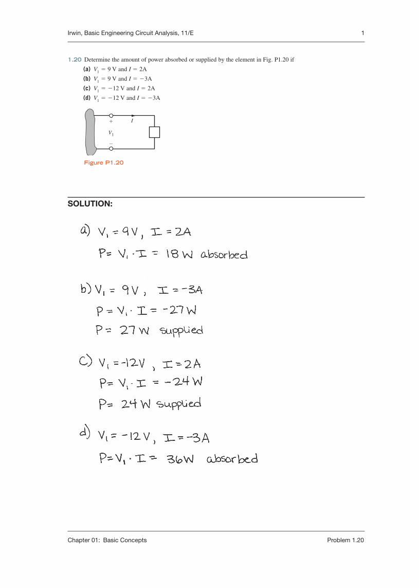
1.20 Determine the amount of power absorbed or supplied by the element in Fig. P1.20 if
(a) V1 = 9 V and I = 2A
(b) V1 = 9 V and I = −3A
(c) V1 = −12 V and I = 2A
(d) V1 = −12 V and I = −3A
+
−
V1
I
Figure P1.20

Irwin, Basic Engineering Circuit Analysis, 11/E 1
Chapter 01: Basic Concepts Problem 1.21
SOLUTION:
1.21 Calculate the power absorbed by element A in Fig. P1.21.
A15 V
3 A
−
+
Figure P1.21

Irwin, Basic Engineering Circuit Analysis, 11/E 1
Chapter 01: Basic Concepts Problem 1.22
SOLUTION:
1.22 Calculate the power supplied by element A in Fig. P1.22.
A20 V
2 A
−
+
Figure P1.22

Irwin, Basic Engineering Circuit Analysis, 11/E 1
Chapter 01: Basic Concepts Problem 1.23
SOLUTION:
1.23 Element A in the diagram in Fig. P1.23 absorbs 30 W of power. Calculate V x .
A
2 A
Vx
−
+
Figure P1.23

Irwin, Basic Engineering Circuit Analysis, 11/E 1
Chapter 01: Basic Concepts Problem 1.24
SOLUTION:
1.24 Element B in the diagram in Fig. P1.24 supplies 60 W of power. Calculate I x .
B24 V
Ix
−
+
Figure P1.24

Irwin, Basic Engineering Circuit Analysis, 11/E 1
Chapter 01: Basic Concepts Problem 1.25
SOLUTION:
1.25 Element B in the diagram in Fig. P1.25 supplies 72 W of power. Calculate V A .
B
3 A
VA–
+
Figure P1.25

Irwin, Basic Engineering Circuit Analysis, 11/E 1
Chapter 01: Basic Concepts Problem 1.26
SOLUTION:
1.26 Element B in the diagram in Fig. P1.26 supplies 72 W of power. Calculate Ix.
B18 V
Ix
−
+
Figure P1.26

Irwin, Basic Engineering Circuit Analysis, 11/E 1
Chapter 01: Basic Concepts Problem 1.27
SOLUTION:
1.27 (a) In Fig. P1.27 (a), P1 = 36 W. Is element 2 absorbing or supplying power, and how much?
(b) In Fig. P1.27 (b), P2 = −48 W. Is element 1 absorbing or supplying power, and how much?
(a) (b)
12 V−
+
6 V−
+
6 V+
−
24 V−
+
1
2
1
2
Figure P1.27

Irwin, Basic Engineering Circuit Analysis, 11/E 1
Chapter 01: Basic Concepts Problem 1.28
SOLUTION:
1.28 Two elements are connected in series, as shown in Fig. P1.28. Element 1 supplies 24 W of power. Is element 2 absorbing or supplying power, and how much?
3 V−
+
6 V+
−
1
2
Figure P1.28

Irwin, Basic Engineering Circuit Analysis, 11/E 1
Chapter 01: Basic Concepts Problem 1.29
SOLUTION:
1.29 Element 2 in Fig. P1.29 absorbed 32 W. Find the power absorbed or supplied by elements 1 and 3.
8 V−
+
12 V−
+
2
4 V+
−1
3
Figure P1.29

Irwin, Basic Engineering Circuit Analysis, 11/E 1
Chapter 01: Basic Concepts Problem 1.30
SOLUTION:
1.30 Choose Is such that the power absorbed by element 2 in Fig. P1.30 is 7 W.
4 V
Is6 V 2 V
+
+
−
−
+
−
1
2
Figure P1.30

Irwin, Basic Engineering Circuit Analysis, 11/E 1
Chapter 01: Basic Concepts Problem 1.31
SOLUTION:
1.31 Find the power that is absorbed or supplied by the circuit elements in Fig. P1.31.
20 V 2 A
2 A
1
14 V+
−
−+ 6 V2 A
+− 16 V 4 A
1
4 A
+
−
−+ 8 V
+−
Ix = 4 A
2Ix
(a) (b)
20 V 2 A
2 A
1
14 V+
−
−+ 6 V2 A
+− 16 V 4 A
1
4 A
+
−
−+ 8 V
+−
Ix = 4 A
2Ix
(a) (b)
Figure P1.31

Irwin, Basic Engineering Circuit Analysis, 11/E 1
Chapter 01: Basic Concepts Problem 1.32
SOLUTION:
1.32 Find the power that is absorbed or supplied by the network elements in Fig. P1.32.
(a)
Ix = 2 A 2 A
2 A
2Ix
1
8 V
12 V
+ −
(b)
Ix = 2 A2 A 2 A
2 A
4Ix 2 12 V+
−
1
20 V24 V+ −
+−
+−
− +
+−
Figure P1.32
Irwin, Basic Engineering Circuit Analysis, 11/E 1
Chapter 01: Basic Concepts Problem 1.33
SOLUTION:
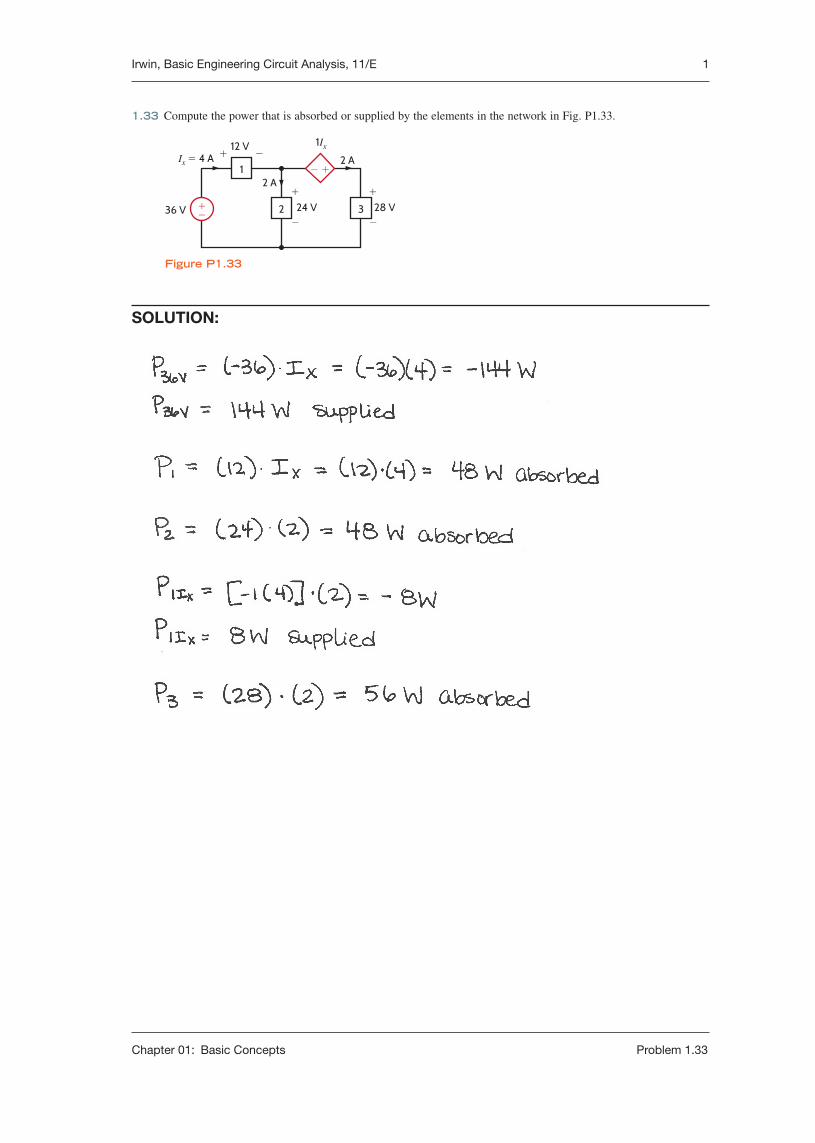
1.33 Compute the power that is absorbed or supplied by the elements in the network in Fig. P1.33.
Ix = 4 A
36 V
2 A
2 A
1Ix
2 3
1 − +
12 V+ −
28 V+
−24 V
+
−+−
Figure P1.33

Irwin, Basic Engineering Circuit Analysis, 11/E 1
Chapter 01: Basic Concepts Problem 1.34
SOLUTION:
1.34 Find the power that is absorbed or supplied by element 2 in Fig. P1.34.
1
4 V
12 V
2 A
2 A
+ −2Vx
−+
2 Vx
+
−+−
Figure P1.34

Irwin, Basic Engineering Circuit Analysis, 11/E 1
Chapter 01: Basic Concepts Problem 1.35
SOLUTION:
1.35 Find Ix in the network in Fig. P1.35.
1
12 V
28 V36 V
Ix
2 A
+ −1Ix
−+
3+
−+−
2 A
2 24 V
+
−
Figure P1.35

Irwin, Basic Engineering Circuit Analysis, 11/E 1
Chapter 01: Basic Concepts Problem 1.36
SOLUTION:
1.36 Determine the power absorbed by element 1 in Fig. P1.36.
1
12 V
16 V36 V
Ix + −2
8 V+ −
2Ix 3+
−+−
2 A
24 V
+
−
Figure P1.36

Irwin, Basic Engineering Circuit Analysis, 11/E 1
Chapter 01: Basic Concepts Problem 1.37
SOLUTION:
1.37 Find the power absorbed or supplied by element 1 in Fig. P1.37.
1
6 V
18 V
Ix
Ix
− +2
4 V+ −
20 V+− 24 V +
−
2 A
2Ix
+
−
Figure P1.37

Irwin, Basic Engineering Circuit Analysis, 11/E 1
Chapter 01: Basic Concepts Problem 1.38
SOLUTION:
1.38 Find the power absorbed or supplied by element 3 in Fig. P1.38.
1
4 V+ −
+−
+−
+−
2 16 V
4 A
2 A
2 A 2 A
12 V
12 V
+
−
3 Vx
2Vx
+
−
4 20 V+
−
2 A
Figure P1.38

Irwin, Basic Engineering Circuit Analysis, 11/E 1
Chapter 01: Basic Concepts Problem 1.39
SOLUTION:
1.39 Find the power absorbed or supplied by element 1 in Fig. P1.39.
1
4 V+ −
4Ix
Ix
+−
3 20 V
+
−4 20 V
+
−2 8 V12 V
4 A
4 A
2 A
12 V
+
−
+
−
Figure P1.39

Irwin, Basic Engineering Circuit Analysis, 11/E 1
Chapter 01: Basic Concepts Problem 1.40
SOLUTION:
1.40 Find Vx in the network in Fig. P1.40 using Tellegen’s theorem.
Vx+ −
321+ −
+ −
24 V12 V
16 V2 A
12 V9 V −+
−+
+−
Figure P1.40

Irwin, Basic Engineering Circuit Analysis, 11/E 1
Chapter 01: Basic Concepts Problem 1.41
SOLUTION:
1.41 Find Ix in the circuit in Fig. P1.41 using Tellegen’s theorem.
IxIx2 A
18 V 12 V+ −
8 V+ −
4 V+ −
6 V
2 A
24 V 2 A+
−12 V+
−+−
−+
Figure P1.41

Irwin, Basic Engineering Circuit Analysis, 11/E 1
Chapter 01: Basic Concepts Problem 1.42
SOLUTION:
1.42 Is the source Vs in the network in Fig. P1.42 absorbing or supplying power, and how much?
3 A 9 A
3 A
VS
+
−8 V
6 A−
+10 V 9 A 16 V
−
+
6 V+ −
+−
Figure P1.42

Irwin, Basic Engineering Circuit Analysis, 11/E 1
Chapter 01: Basic Concepts Problem 1.43
SOLUTION:
1.43 Find Io in the network in Fig. P1.43 using Tellegen’s theorem.
Ix=2 A
Io
4Ix
+4
5
2
+−
6
3
1
6 V−
+−8 V
8 V+ −
16 V
24 V
3 A
3 A
6 A
4 A
1 A
+
−
10 V
+
−
6 V+
−
+−
Figure P1.43

Irwin, Basic Engineering Circuit Analysis, 11/E 1
Chapter 01: Basic Concepts Problem 1.44
SOLUTION:
1.44 Calculate the power absorbed by each element in the circuit in Fig. P1.44. Also, verify that Tellegen’s theorem is satisfied by this circuit.
5
24 V+ −
12 V+ −
3Ix
−+
1 22 A
2 A
4 A
6 A
4 A
12 V
4
9 V
24 V +−
3 15 V6 V
+
−
+
−
− +6 V
+ −
4 A
2 A
Ix = 2 A
+−
Figure P1.44

Irwin, Basic Engineering Circuit Analysis, 11/E 1
Chapter 01: Basic Concepts Problem 1.45
SOLUTION:
1.45 Calculate the power absorbed by each element in the circuit in Fig. P1.45. Also, verify that Tellegen’s theorem is satisfied by this circuit.
5
30 V
40 V
1
5 V+ −2
1 A
5 A
+−
+−
4 A
4 A
3 A
1 A
15 V
4
5 V+ −
+
−5 V
−
+
10 V
+
−
3
10 V+ −
Figure P1.45

Irwin, Basic Engineering Circuit Analysis, 11/E 1
Chapter 01: Basic Concepts Problem 1.46
SOLUTION:
1.46 In the circuit in Fig. P1.46, element 1 absorbs 40 W, element 2 supplies 50 W, element 3 supplies 25 W, and element 4 absorbs 15 W. How much power is supplied by element 5?
543
1 2
Figure P1.46