SolidWorks Tutorial 5 TIC-TAC-TOE - Harran...
33
SolidWorks ® Tutorial 5 TIC-TAC-TOE
Transcript of SolidWorks Tutorial 5 TIC-TAC-TOE - Harran...
SolidWorks® Tutorial 5
TIC-TAC-TOE
Tutorial 5: Tic Tac Toe 2
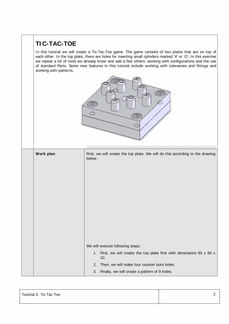
TIC-TAC-TOEIn this tutorial we will create a Tic-Tac-Toe game. The game consists of two plates that are on top ofeach other. In the top plate, there are holes for inserting small cylinders marked ‘X’ or ‘O’. In this exercisewe repeat a lot of tools we already know and add a few others: working with configurations and the useof standard Parts. Some new features in this tutorial include working with tolerances and fittings andworking with patterns.
Work plan First, we will create the top plate. We will do this according to the drawingbelow.
We will execute following steps:
1. First, we will create the top plate first with dimensions 60 x 60 x10.
2. Then, we will make four counter bore holes.
3. Finally, we will create a pattern of 9 holes.
Tutorial 5: Tic Tac Toe 3
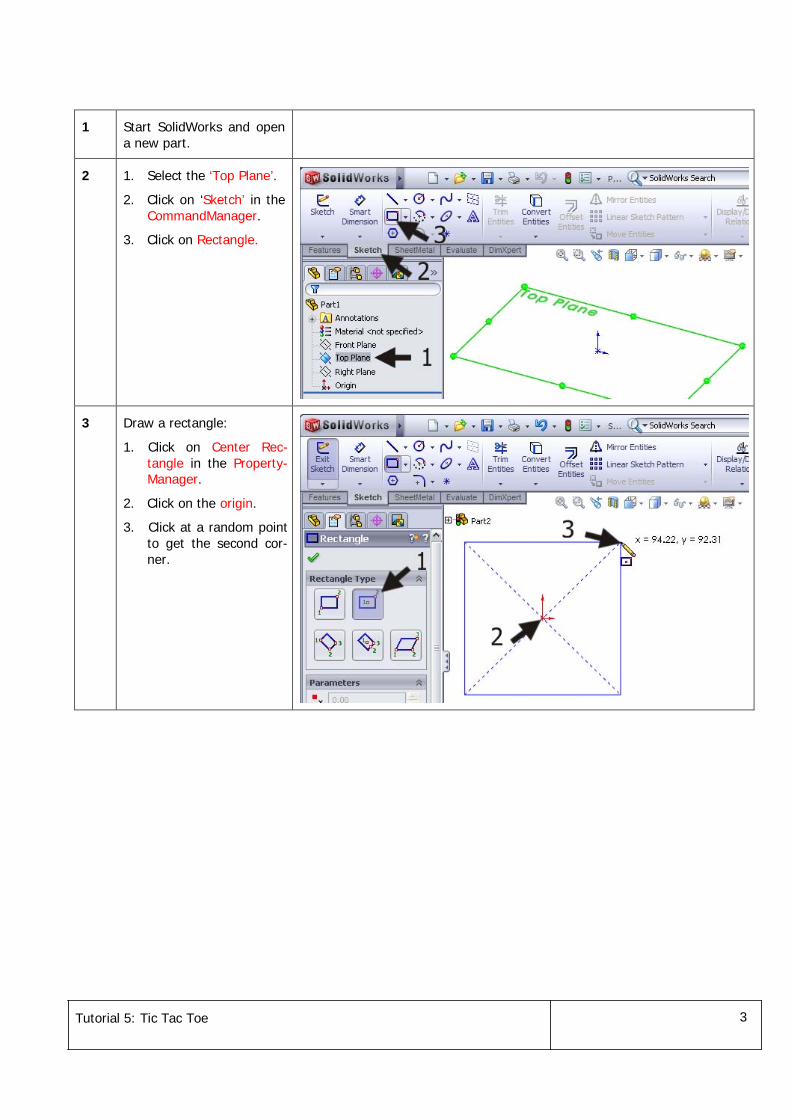
1 Start SolidWorks and opena new part.
2 1. Select the ‘Top Plane’.
2. Click on ‘Sketch’ in theCommandManager.
3. Click on Rectangle.
3 Draw a rectangle:
1. Click on Center Rec-tangle in the Property-Manager.
2. Click on the origin.
3. Click at a random pointto get the second cor-ner.
Tutorial 5: Tic Tac Toe 4
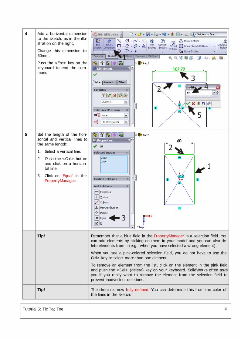
4 Add a horizontal dimensionto the sketch, as in the illu-stration on the right.
Change this dimension to60mm.
Push the <Esc> key on thekeyboard to end the com-mand.
5 Set the length of the hori-zontal and vertical lines tothe same length:
1. Select a vertical line.
2. Push the <Ctrl> buttonand click on a horizon-tal line.
3. Click on ‘Equal’ in thePropertyManager.
Tip! Remember that a blue field in the PropertyManager is a selection field. Youcan add elements by clicking on them in your model and you can also de-lete elements from it (e.g., when you have selected a wrong element).
When you see a pink-colored selection field, you do not have to use theCtrl> key to select more than one element.
To remove an element from the list, click on the element in the pink fieldand push the <Del> (delete) key on your keyboard. SolidWorks often asksyou if you really want to remove the element from the selection field toprevent inadvertent deletions.
Tip! The sketch is now fully defined. You can determine this from the color ofthe lines in the sketch:
Tutorial 5: Tic Tac Toe 5
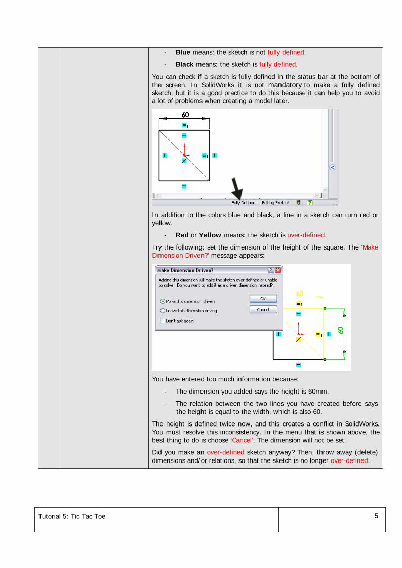
- Blue means: the sketch is not fully defined.
- Black means: the sketch is fully defined.
You can check if a sketch is fully defined in the status bar at the bottom ofthe screen. In SolidWorks it is not mandatory to make a fully definedsketch, but it is a good practice to do this because it can help you to avoida lot of problems when creating a model later.
In addition to the colors blue and black, a line in a sketch can turn red oryellow.
- Red or Yellow means: the sketch is over-defined.
Try the following: set the dimension of the height of the square. The ‘MakeDimension Driven?’ message appears:
You have entered too much information because:
- The dimension you added says the height is 60mm.
- The relation between the two lines you have created before saysthe height is equal to the width, which is also 60.
The height is defined twice now, and this creates a conflict in SolidWorks.You must resolve this inconsistency. In the menu that is shown above, thebest thing to do is choose ‘Cancel’. The dimension will not be set.
Did you make an over-defined sketch anyway? Then, throw away (delete)dimensions and/or relations, so that the sketch is no longer over-defined.
Tutorial 5: Tic Tac Toe 6
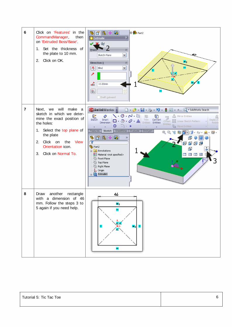
6 Click on ‘Features’ in theCommandManager, thenon ‘Extruded Boss/Base’.
1. Set the thickness ofthe plate to 10 mm.
2. Click on OK.
7 Next, we will make asketch in which we deter-mine the exact position ofthe holes:
1. Select the top plane ofthe plate
2. Click on the ViewOrientation icon.
3. Click on Normal To.
8 Draw another rectanglewith a dimension of 46mm. Follow the steps 3 to5 again if you need help.
Tutorial 5: Tic Tac Toe 7
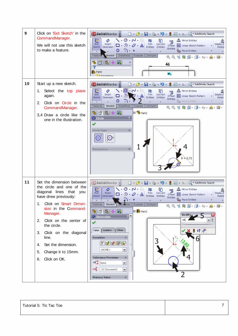
9 Click on ‘Exit Sketch’ in theCommandManager.
We will not use this sketchto make a feature.
10 Start up a new sketch.
1. Select the top planeagain.
2. Click on Circle in theCommandManager.
3,4 Draw a circle like theone in the illustration.
11 Set the dimension betweenthe circle and one of thediagonal lines that youhave drew previously:
1. Click on Smart Dimen-sion in the Command-Manager.
2. Click on the center ofthe circle.
3. Click on the diagonalline.
4. Set the dimension.
5. Change it to 15mm.
6. Click on OK.
Tutorial 5: Tic Tac Toe 8
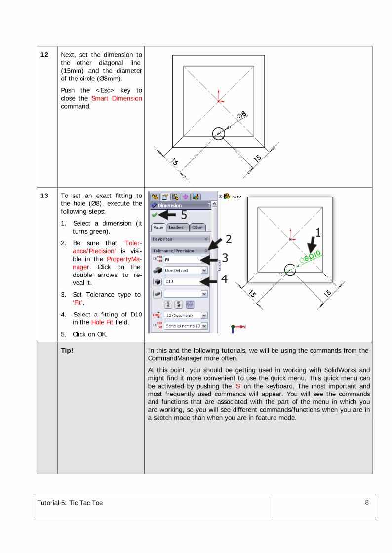
12 Next, set the dimension tothe other diagonal line(15mm) and the diameterof the circle (Ø8mm).
Push the <Esc> key toclose the Smart Dimensioncommand.
13 To set an exact fitting tothe hole (Ø8), execute thefollowing steps:
1. Select a dimension (itturns green).
2. Be sure that ‘Toler-ance/Precision’ is visi-ble in the PropertyMa-nager. Click on thedouble arrows to re-veal it.
3. Set Tolerance type to‘Fit’.
4. Select a fitting of D10in the Hole Fit field.
5. Click on OK.
Tip! In this and the following tutorials, we will be using the commands from theCommandManager more often.
At this point, you should be getting used in working with SolidWorks andmight find it more convenient to use the quick menu. This quick menu canbe activated by pushing the ‘S’ on the keyboard. The most important andmost frequently used commands will appear. You will see the commandsand functions that are associated with the part of the menu in which youare working, so you will see different commands/functions when you are ina sketch mode than when you are in feature mode.
Tutorial 5: Tic Tac Toe 9
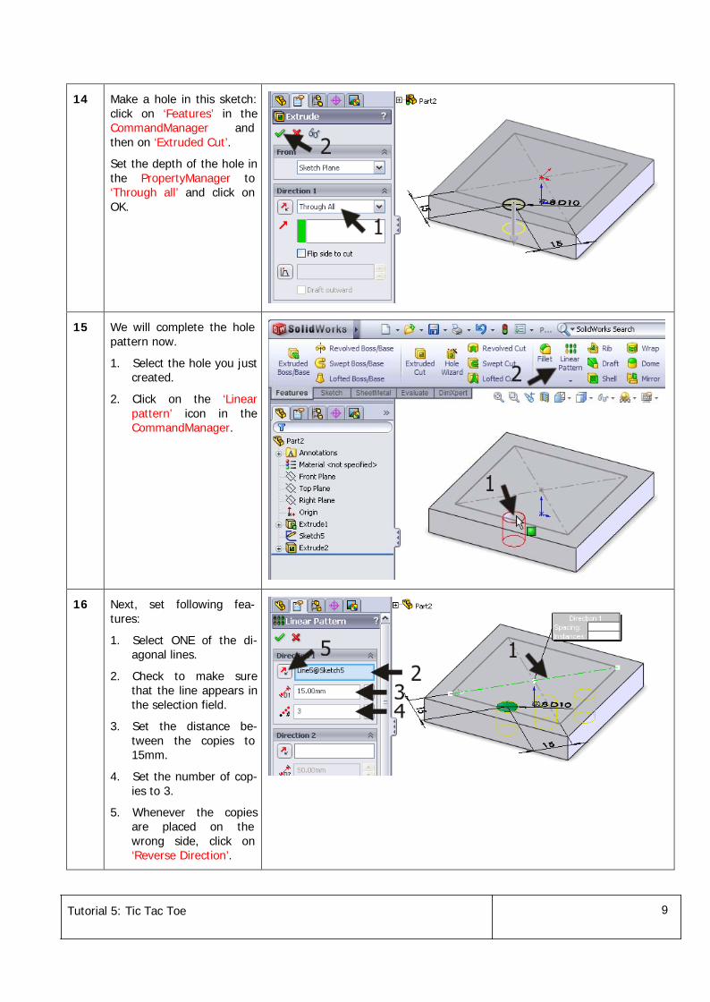
14 Make a hole in this sketch:click on ‘Features’ in theCommandManager andthen on ‘Extruded Cut’.
Set the depth of the hole inthe PropertyManager to‘Through all’ and click onOK.
15 We will complete the holepattern now.
1. Select the hole you justcreated.
2. Click on the ‘Linearpattern’ icon in theCommandManager.
16 Next, set following fea-tures:
1. Select ONE of the di-agonal lines.
2. Check to make surethat the line appears inthe selection field.
3. Set the distance be-tween the copies to15mm.
4. Set the number of cop-ies to 3.
5. Whenever the copiesare placed on thewrong side, click on‘Reverse Direction’.
Tutorial 5: Tic Tac Toe 10
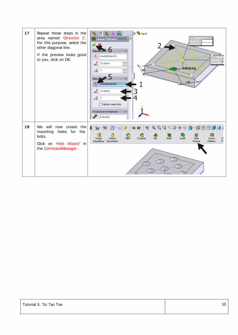
17 Repeat these steps in thearea named ‘Direction 2’.For this purpose, select theother diagonal line.
If the preview looks goodto you, click on OK.
18 We will now create themounting holes for thebolts.
Click on ‘Hole Wizard’ inthe CommandManager.
Tutorial 5: Tic Tac Toe 11
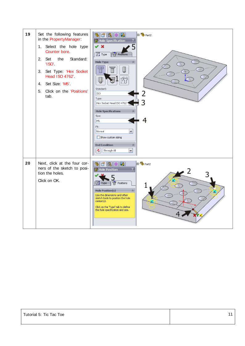
19 Set the following featuresin the PropertyManager:
1. Select the hole typeCounter bore.
2. Set the Standard:‘ISO’.
3. Set Type: ‘Hex SocketHead ISO 4762’.
4. Set Size: ‘M5’.
5. Click on the ‘Positions’tab.
20 Next, click at the four cor-ners of the sketch to posi-tion the holes.
Click on OK.
Tutorial 5: Tic Tac Toe 12
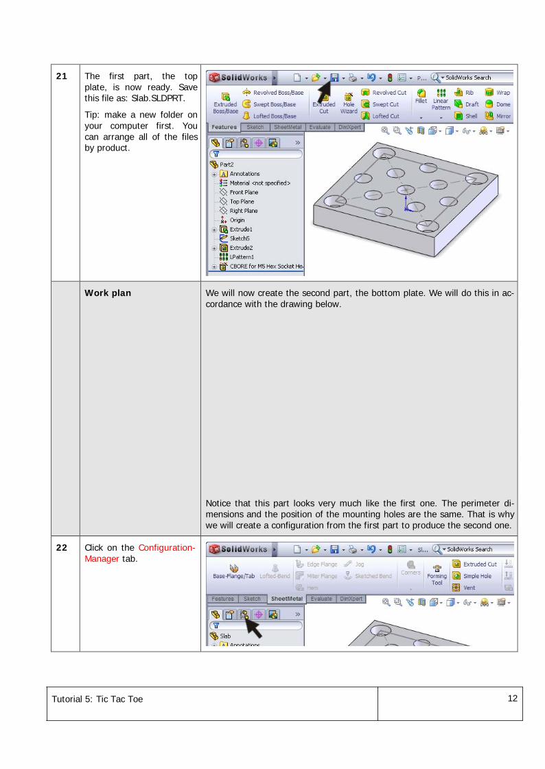
21 The first part, the topplate, is now ready. Savethis file as: Slab.SLDPRT.
Tip: make a new folder onyour computer first. Youcan arrange all of the filesby product.
Work plan We will now create the second part, the bottom plate. We will do this in ac-cordance with the drawing below.
Notice that this part looks very much like the first one. The perimeter di-mensions and the position of the mounting holes are the same. That is whywe will create a configuration from the first part to produce the second one.
22 Click on the Configuration-Manager tab.
Tutorial 5: Tic Tac Toe 13
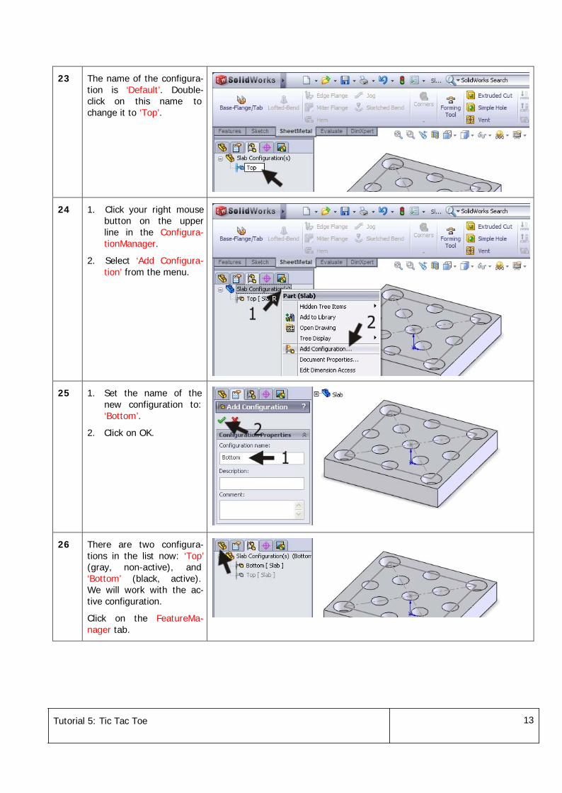
23 The name of the configura-tion is ‘Default’. Double-click on this name tochange it to ‘Top’.
24 1. Click your right mousebutton on the upperline in the Configura-tionManager.
2. Select ‘Add Configura-tion’ from the menu.
25 1. Set the name of thenew configuration to:‘Bottom’.
2. Click on OK.
26 There are two configura-tions in the list now: ‘Top’(gray, non-active), and‘Bottom’ (black, active).We will work with the ac-tive configuration.
Click on the FeatureMa-nager tab.
Tutorial 5: Tic Tac Toe 14
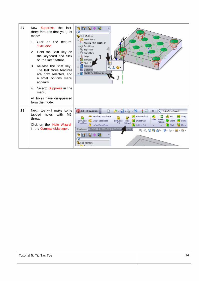
27 Now Suppress the lastthree features that you justmade:
1. Click on the feature‘Extrude2’.
2. Hold the Shift key onthe keyboard and clickon the last feature.
3. Release the Shift key.The last three featuresare now selected, anda small options menuappears.
4. Select: Suppress in themenu.
All holes have disappearedfrom the model.
28 Next, we will make sometapped holes with M5thread.
Click on the ‘Hole Wizard’in the CommandManager.
Tutorial 5: Tic Tac Toe 15
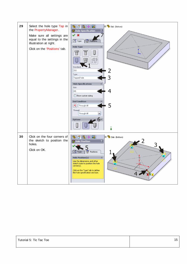
29 Select the hole type Tap inthe PropertyManager.
Make sure all settings areequal to the settings in theillustration at right.
Click on the ‘Positions’ tab.
30 Click on the four corners ofthe sketch to position theholes.
Click on OK.
Tutorial 5: Tic Tac Toe 16
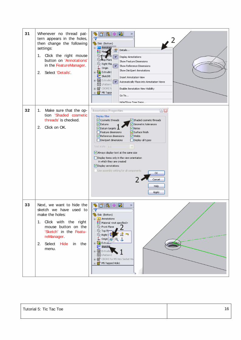
31 Whenever no thread pat-tern appears in the holes,then change the followingsettings:
1. Click the right mousebutton on ‘Annotations’in the FeatureManager.
2. Select ‘Details’.
32 1. Make sure that the op-tion ‘Shaded cosmeticthreads’ is checked.
2. Click on OK.
33 Next, we want to hide thesketch we have used tomake the holes:
1. Click with the rightmouse button on the‘Sketch’ in the Featu-reManager.
2. Select Hide in themenu.
Tutorial 5: Tic Tac Toe 17
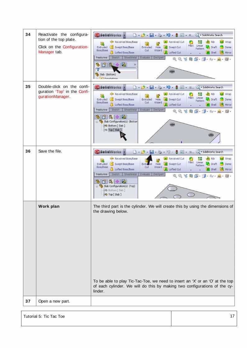
34 Reactivate the configura-tion of the top plate.
Click on the Configuration-Manager tab.
35 Double-click on the confi-guration ‘Top’ in the Confi-gurationManager.
36 Save the file.
Work plan The third part is the cylinder. We will create this by using the dimensions ofthe drawing below.
To be able to play Tic-Tac-Toe, we need to insert an ‘X’ or an ‘O’ at the topof each cylinder. We will do this by making two configurations of the cy-linder.
37 Open a new part.
Tutorial 5: Tic Tac Toe 18
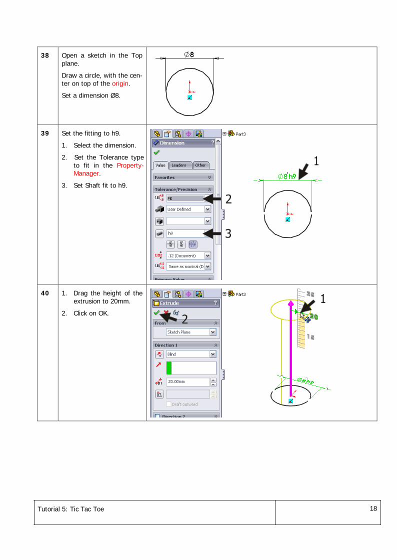
38 Open a sketch in the Topplane.
Draw a circle, with the cen-ter on top of the origin.
Set a dimension Ø8.
39 Set the fitting to h9.
1. Select the dimension.
2. Set the Tolerance typeto fit in the Property-Manager.
3. Set Shaft fit to h9.
40 1. Drag the height of theextrusion to 20mm.
2. Click on OK.
Tutorial 5: Tic Tac Toe 19
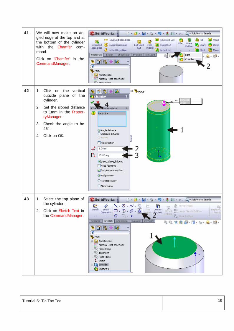
41 We will now make an an-gled edge at the top and atthe bottom of the cylinderwith the Chamfer com-mand.
Click on ‘Chamfer’ in theCommandManager.
42 1. Click on the verticaloutside plane of thecylinder.
2. Set the sloped distanceto 1mm in the Proper-tyManager.
3. Check the angle to be45°.
4. Click on OK.
43 1. Select the top plane ofthe cylinder.
2. Click on Sketch Text inthe CommandManager.
Tutorial 5: Tic Tac Toe 20
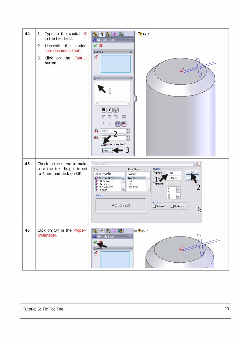
44 1. Type in the capital ‘X’in the text field.
2. Uncheck the option‘Use document font’.
3. Click on the ‘Font…’button.
45 Check in the menu to makesure the text height is setto 4mm, and click on OK.
46 Click on OK in the Proper-tyManager.
Tutorial 5: Tic Tac Toe 21
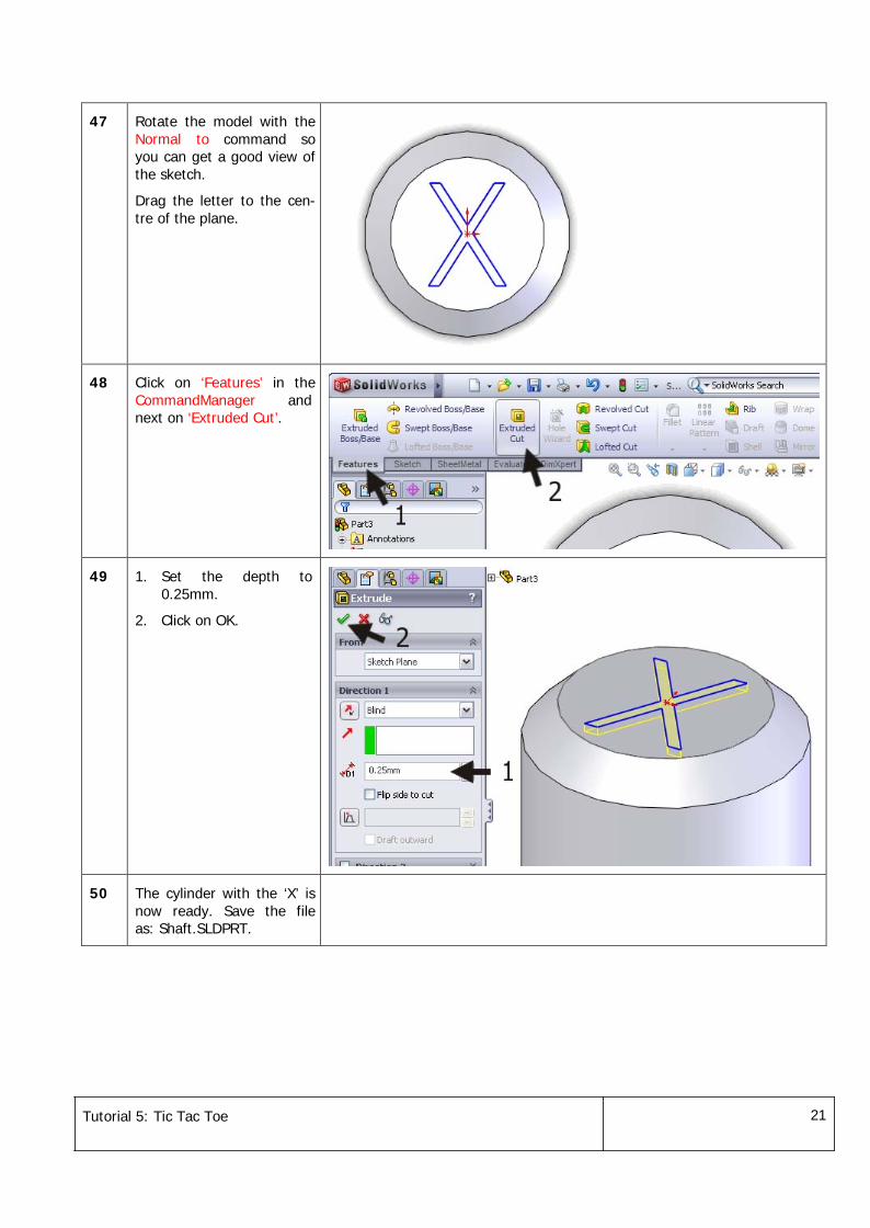
47 Rotate the model with theNormal to command soyou can get a good view ofthe sketch.
Drag the letter to the cen-tre of the plane.
48 Click on ‘Features’ in theCommandManager andnext on ‘Extruded Cut’.
49 1. Set the depth to0.25mm.
2. Click on OK.
50 The cylinder with the ‘X’ isnow ready. Save the fileas: Shaft.SLDPRT.
Tutorial 5: Tic Tac Toe 22
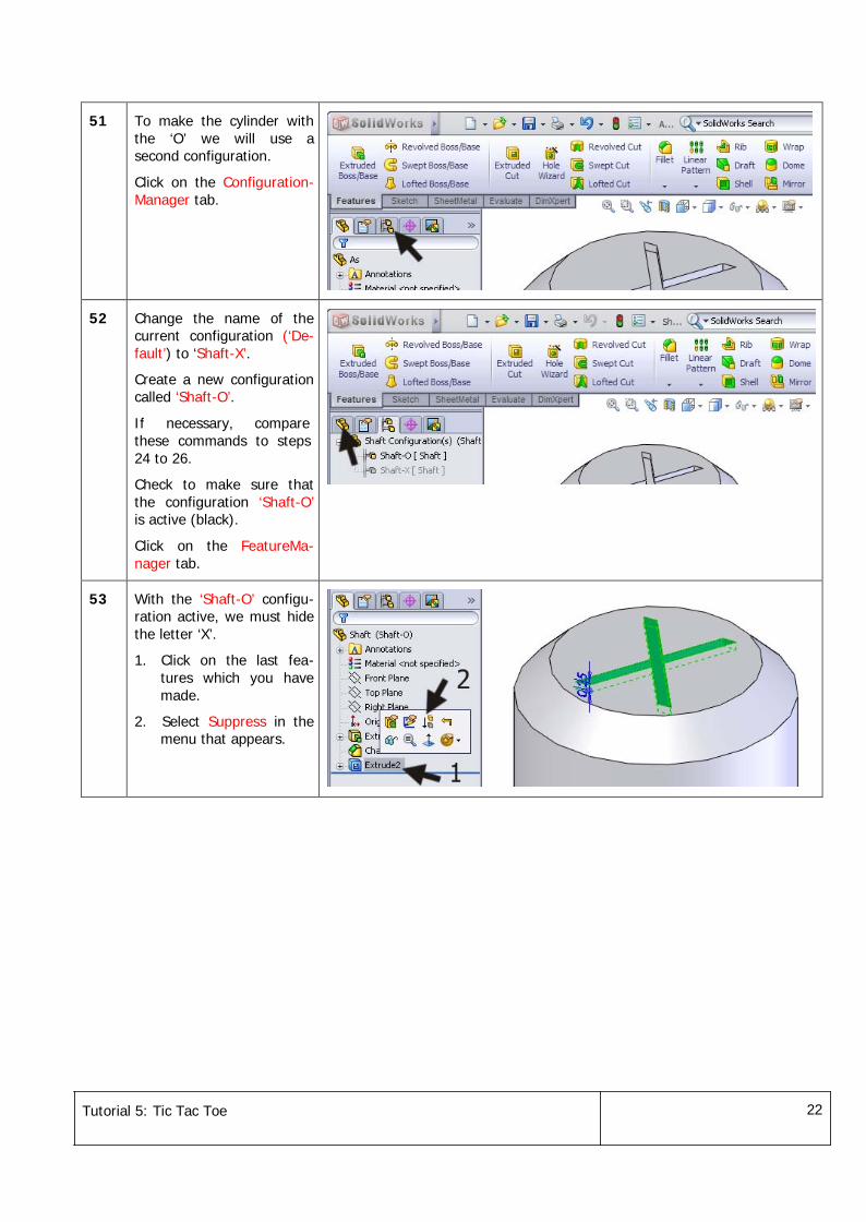
51 To make the cylinder withthe ‘O’ we will use asecond configuration.
Click on the Configuration-Manager tab.
52 Change the name of thecurrent configuration (‘De-fault’) to ‘Shaft-X’.
Create a new configurationcalled ‘Shaft-O’.
If necessary, comparethese commands to steps24 to 26.
Check to make sure thatthe configuration ‘Shaft-O’is active (black).
Click on the FeatureMa-nager tab.
53 With the ‘Shaft-O’ configu-ration active, we must hidethe letter ‘X’.
1. Click on the last fea-tures which you havemade.
2. Select Suppress in themenu that appears.
Tutorial 5: Tic Tac Toe 23
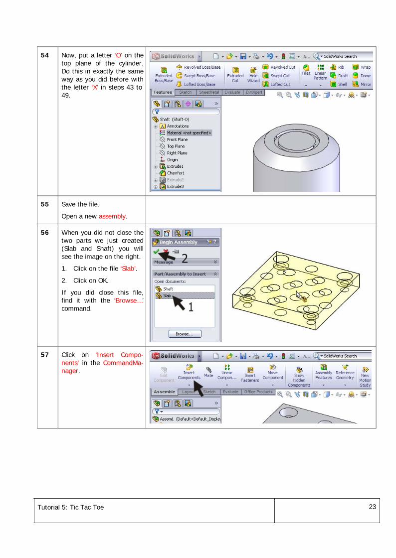
54 Now, put a letter ‘O’ on thetop plane of the cylinder.Do this in exactly the sameway as you did before withthe letter ‘X’ in steps 43 to49.
55 Save the file.
Open a new assembly.
56 When you did not close thetwo parts we just created(Slab and Shaft) you willsee the image on the right.
1. Click on the file ‘Slab’.
2. Click on OK.
If you did close this file,find it with the ‘Browse…’command.
57 Click on ‘Insert Compo-nents’ in the CommandMa-nager.
Tutorial 5: Tic Tac Toe 24
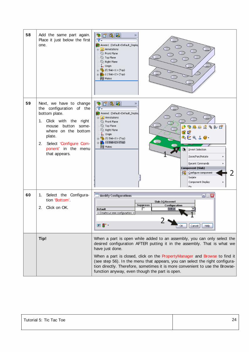
58 Add the same part again.Place it just below the firstone.
59 Next, we have to changethe configuration of thebottom plate.
1. Click with the rightmouse button some-where on the bottomplate.
2. Select ‘Configure Com-ponent’ in the menuthat appears.
60 1. Select the Configura-tion ‘Bottom’.
2. Click on OK.
Tip! When a part is open while added to an assembly, you can only select thedesired configuration AFTER putting it in the assembly. That is what wehave just done.
When a part is closed, click on the PropertyManager and Browse to find it(see step 56). In the menu that appears, you can select the right configura-tion directly. Therefore, sometimes it is more convenient to use the Browse-function anyway, even though the part is open.
Tutorial 5: Tic Tac Toe 25
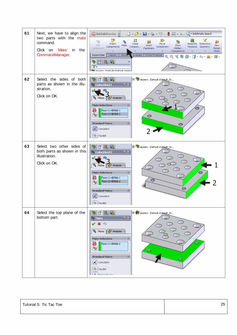
61 Next, we have to align thetwo parts with the matecommand.
Click on ‘Mate’ in theCommandManager.
62 Select the sides of bothparts as shown in the illu-stration.
Click on OK.
63 Select two other sides ofboth parts as shown in thisillustration.
Click on OK.
64 Select the top plane of thebottom part.
Tutorial 5: Tic Tac Toe 26
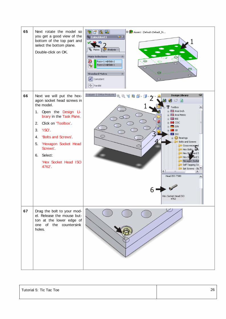
65 Next rotate the model soyou get a good view of thebottom of the top part andselect the bottom plane.
Double-click on OK.
66 Next we will put the hex-agon socket head screws inthe model.
1. Open the Design Li-brary in the Task Pane.
2. Click on ‘Toolbox’.
3. ‘ISO’.
4. ‘Bolts and Screws’.
5. ‘Hexagon Socket HeadScrews’.
6. Select:
‘Hex Socket Head ISO4762’.
67 Drag the bolt to your mod-el. Release the mouse but-ton at the lower edge ofone of the countersinkholes.
Tutorial 5: Tic Tac Toe 27
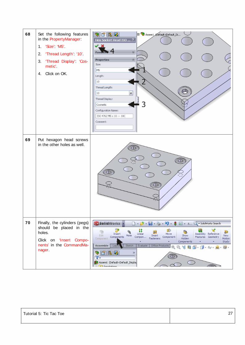
68 Set the following featuresin the PropertyManager:
1. ‘Size’: ‘M5’.
2. ‘Thread Length’: ‘10’.
3. ‘Thread Display’: ‘Cos-metic’.
4. Click on OK.
69 Put hexagon head screwsin the other holes as well.
70 Finally, the cylinders (pegs)should be placed in theholes.
Click on ‘Insert Compo-nents’ in the CommandMa-nager.
Tutorial 5: Tic Tac Toe 28
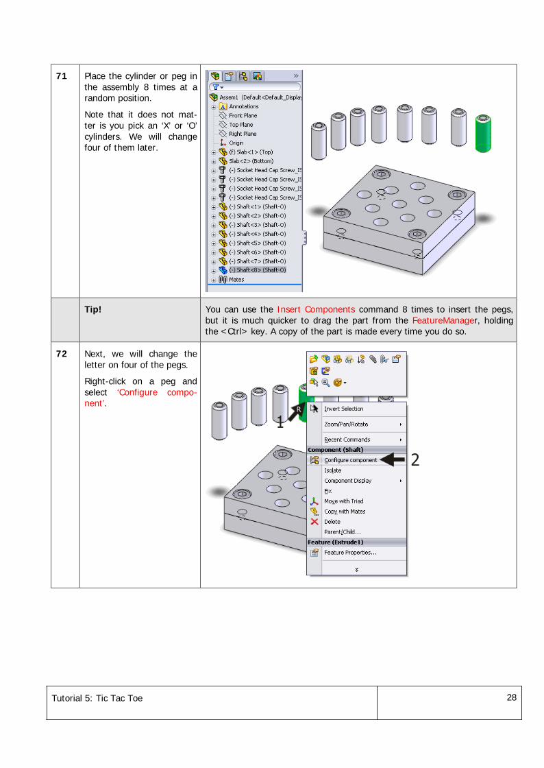
71 Place the cylinder or peg inthe assembly 8 times at arandom position.
Note that it does not mat-ter is you pick an ‘X’ or ‘O’cylinders. We will changefour of them later.
Tip! You can use the Insert Components command 8 times to insert the pegs,but it is much quicker to drag the part from the FeatureManager, holdingthe <Ctrl> key. A copy of the part is made every time you do so.
72 Next, we will change theletter on four of the pegs.
Right-click on a peg andselect ‘Configure compo-nent’.
Tutorial 5: Tic Tac Toe 29
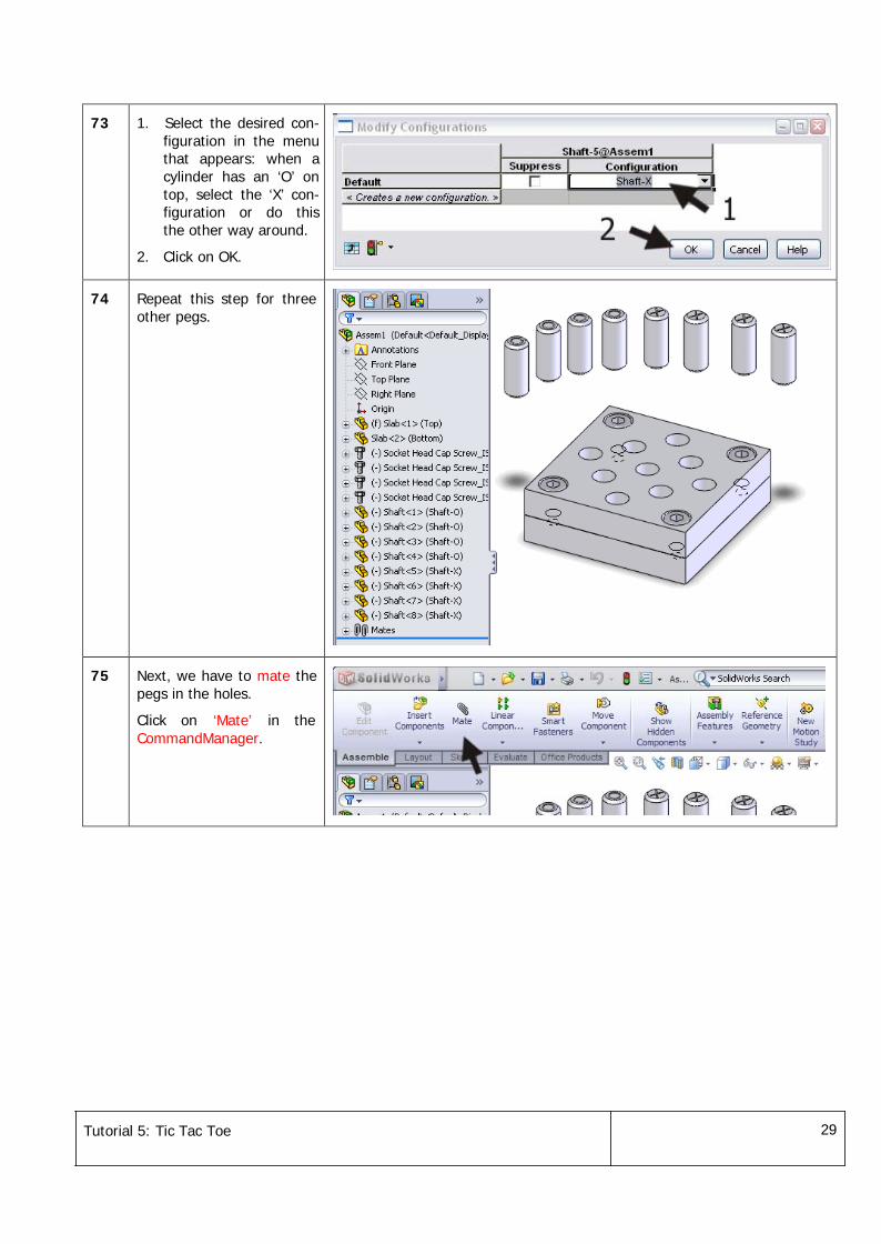
73 1. Select the desired con-figuration in the menuthat appears: when acylinder has an ‘O’ ontop, select the ‘X’ con-figuration or do thisthe other way around.
2. Click on OK.
74 Repeat this step for threeother pegs.
75 Next, we have to mate thepegs in the holes.
Click on ‘Mate’ in theCommandManager.
Tutorial 5: Tic Tac Toe 30
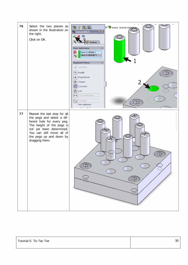
76 Select the two planes asshown in the illustration onthe right.
Click on OK.
77 Repeat the last step for allthe pegs and select a dif-ferent hole for every peg.The height of the pegs isnot yet been determined.You can still move all ofthe pegs up and down bydragging them.
Tutorial 5: Tic Tac Toe 31
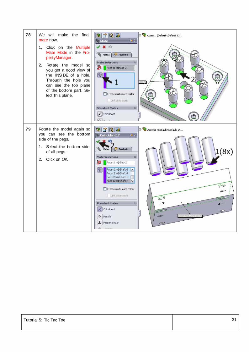
78 We will make the finalmate now.
1. Click on the MultipleMate Mode in the Pro-pertyManager.
2. Rotate the model soyou get a good view ofthe INSIDE of a hole.Through the hole youcan see the top planeof the bottom part. Se-lect this plane.
79 Rotate the model again soyou can see the bottomside of the pegs.
1. Select the bottom sideof all pegs.
2. Click on OK.
Tutorial 5: Tic Tac Toe 32
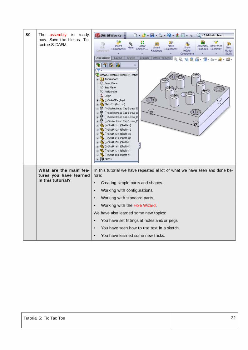
80 The assembly is readynow. Save the file as: Tic-tactoe.SLDASM.
What are the main fea-tures you have learnedin this tutorial?
In this tutorial we have repeated al lot of what we have seen and done be-fore:
• Creating simple parts and shapes.
• Working with configurations.
• Working with standard parts.
• Working with the Hole Wizard.
We have also learned some new topics:
• You have set fittings at holes and/or pegs.
• You have seen how to use text in a sketch.
• You have learned some new tricks.

Tutorial 5: Tic Tac Toe 33