SolidWorks 2000 - Old Dominion Universitybao/xmodulece5.pdf · Fall 2001 H.P. Bao. Dept of ME 4...
25
Fall 2001 H.P. Bao. Dept of ME 1 SolidWorks 2000 Tutorial
Transcript of SolidWorks 2000 - Old Dominion Universitybao/xmodulece5.pdf · Fall 2001 H.P. Bao. Dept of ME 4...
Fall 2001 H.P. Bao. Dept of ME 1
SolidWorks 2000
Tutorial

Fall 2001 H.P. Bao. Dept of ME 2
Fundamental features of SolidModeling
• Parts are designed as solids, ie 3-D

Fall 2001 H.P. Bao. Dept of ME 3
Fundamental features of SolidModeling
2. SolidWorks is a dimension-driven system

Fall 2001 H.P. Bao. Dept of ME 4
Fundamental features of SolidModeling
3. A SolidWorks 3D model consists of parts,assemblies, and 2-D drawings
Part Model

Fall 2001 H.P. Bao. Dept of ME 5
Assembly• Assembly Model
Fall 2001 H.P. Bao. Dept of ME 6
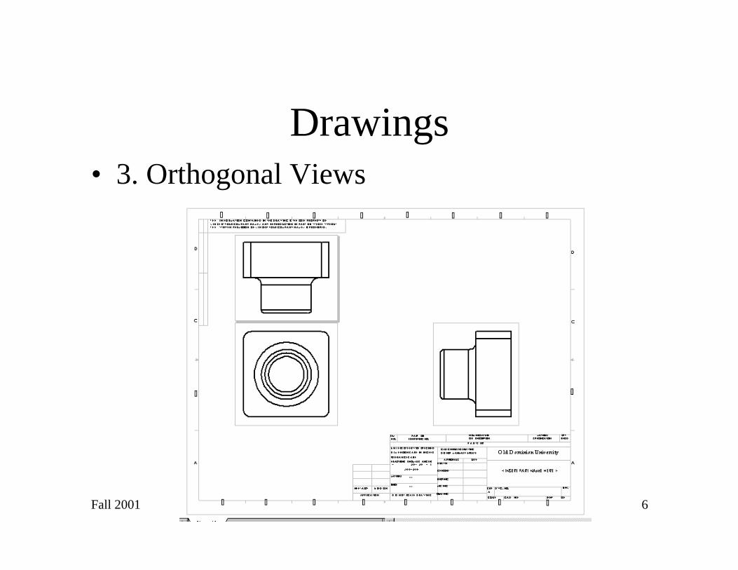
Drawings• 3. Orthogonal Views

Fall 2001 H.P. Bao. Dept of ME 7
Other Features
• Sectional View:

Fall 2001 H.P. Bao. Dept of ME 8
Other Features
• Measure any
dimension:

Fall 2001 H.P. Bao. Dept of ME 9
Other Features• Material Properties:

Fall 2001 H.P. Bao. Dept of ME 10
Useful Keys
• “F” key to fit design to window
• “Z” key to zoom out
• Shift “Z” key to zoom in
• Ctrl “Z” key to cancel last command
• “ESC” key to disable latest operation mode
• “Space Bar” to select different views
Fall 2001 H.P. Bao. Dept of ME 11
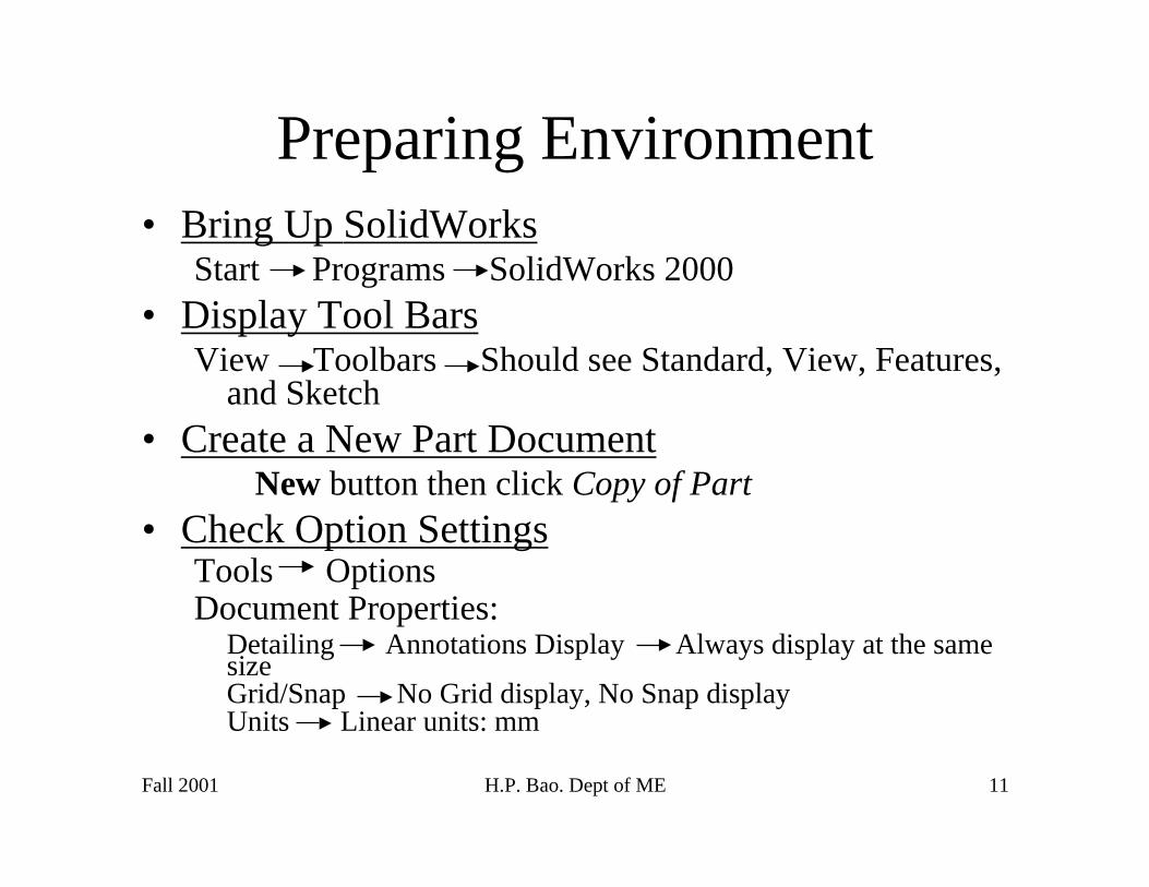
Preparing Environment• Bring Up SolidWorks
Start Programs SolidWorks 2000• Display Tool Bars
View Toolbars Should see Standard, View, Features,and Sketch
• Create a New Part Document New button then click Copy of Part
• Check Option SettingsTools OptionsDocument Properties:
Detailing Annotations Display Always display at the samesizeGrid/Snap No Grid display, No Snap displayUnits Linear units: mm

Fall 2001 H.P. Bao. Dept of ME 12
Practice – Part1
Objective is to create this part
• Create a New PartClick (New) then click Copy of Part
• Check Options (as before)
• Open a sketchClick
Build Base-Extrude 120x120x50 mm high

Fall 2001 H.P. Bao. Dept of ME 13
First Practice
4. Open a sketch then build Boss-Extrude170 mm dia x 25 mm high
5. Open a sketch then build Cut-Extrude150 mm dia then extrude cut through all
6. Shell partSelect surface then click shell icon, 2mm thick
6. Add fillet1 to 4 corners at 10 mm7. Add fillet2 to 4 edges and base of Boss-Extrude1
at 5 mm

Fall 2001 H.P. Bao. Dept of ME 14
First Practice: Final Result
Save as tutor1.sldprt
Fall 2001 H.P. Bao. Dept of ME 15
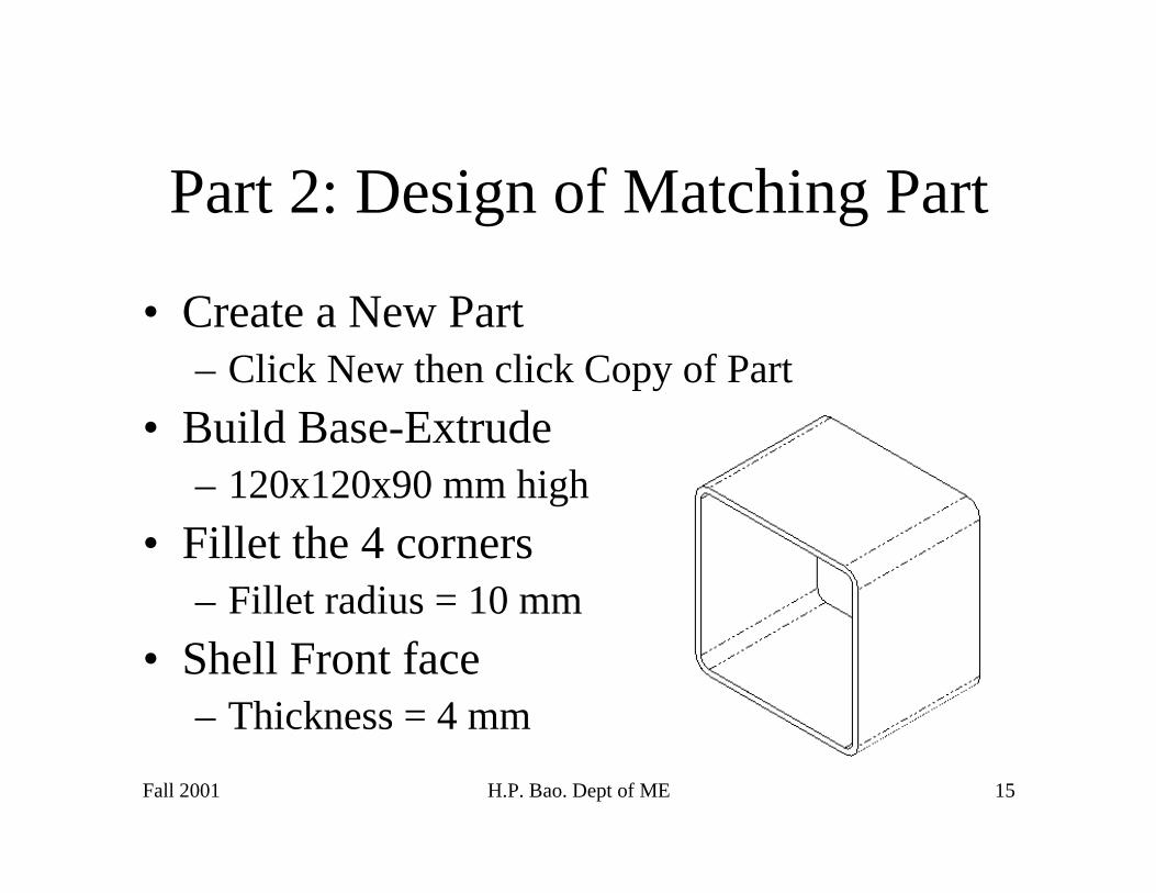
Part 2: Design of Matching Part
• Create a New Part– Click New then click Copy of Part
• Build Base-Extrude– 120x120x90 mm high
• Fillet the 4 corners– Fillet radius = 10 mm
• Shell Front face– Thickness = 4 mm

Fall 2001 H.P. Bao. Dept of ME 16
Design of Matching Part• Create a Lip
– Zoom in at a corner of a wall
– Select front surface and open a sketch
– Click Convert Entity
– Click front surface
– Click Offset Entities, 2 mm
– Click Extrude Cut at depth of 30 mm
• Save as tutor2.sldprt

Fall 2001 H.P. Bao. Dept of ME 17
Design of Matching Part
Fall 2001 H.P. Bao. Dept of ME 18
Part 3: Design of Assembly
• Open both Tutor1 and Tutor2
• Open a New Assembly Design:– Click New then select Open Assembly
• Show all three designs:– Click Window then click Tile Horizontally
– Drag Tutor 1 from Feature Manager to Assembly Panel
– Drag Tutor2 from Feature Manager to Assembly Panel
– Delete Tutor1 and Tutor2 Panels
Fall 2001 H.P. Bao. Dept of ME 19
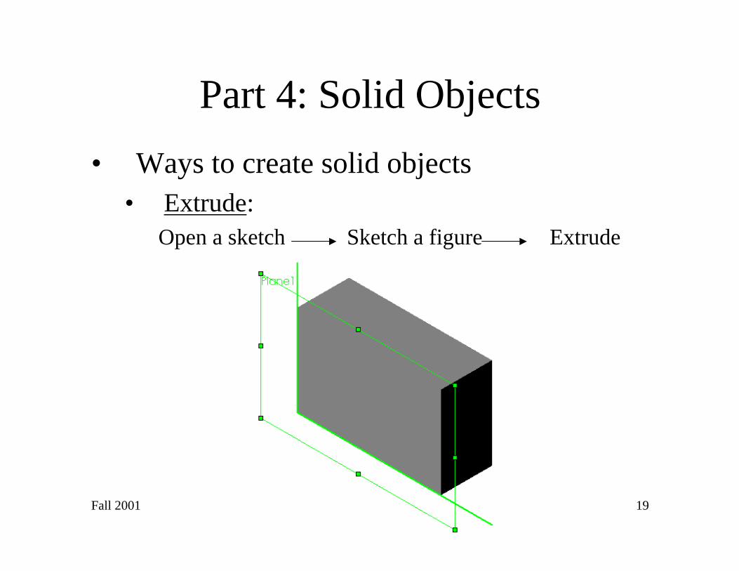
Part 4: Solid Objects
• Ways to create solid objects• Extrude:
Open a sketch Sketch a figure Extrude

Fall 2001 H.P. Bao. Dept of ME 20
1- Ways to create object solid• Revolve:
– Requires a Center Line
– Sketch a close contour, click Insert, then Basethen revolve.

Fall 2001 H.P. Bao. Dept of ME 21
1. Ways to create solid object• Sweep:
– Sketch a close profile on one plane
– Sketch sweep path on another plane
– Click Insert, then Base, then Sweep
– Specify sweep section, sweep path

Fall 2001 H.P. Bao. Dept of ME 22
1. Ways to create solid object
• Loft:– First, create a series of
reference planes, sayP4, P5, and P6; allparallel to P1
– Sketch a close profileon each of P1, P4, P5,P6
– Click Loft feature thenspecify the sketches insequence

Fall 2001 H.P. Bao. Dept of ME 23
2- Add relations
• Examples of relations:collinear, parallel,concentric, equal, etc…
• Example of part withconcentric features:– Open sketch, sketch circular
profile then extrude– Open sketch on front face
of cylinder, sketch circle– Click Add Relations icon,
then specify relation– Extrude boss
Fall 2001 H.P. Bao. Dept of ME 24
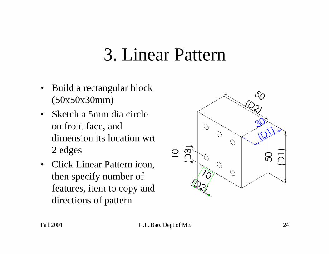
3. Linear Pattern
• Build a rectangular block(50x50x30mm)
• Sketch a 5mm dia circleon front face, anddimension its location wrt2 edges
• Click Linear Pattern icon,then specify number offeatures, item to copy anddirections of pattern

Fall 2001 H.P. Bao. Dept of ME 25
4. Circular Pattern
• Build a rectangular block(50x50x30mm)
• Sketch a 5mm dia circleon front face, anddimension its location wrta reference center line
• Click Linear Pattern icon,then specify number offeatures, item to copy anddirections of pattern