Solid Rocket Boosters and Post-Launch Processing … 2/Solid Rocket Boosters...Solid Rocket Boosters...
5
Solid Rocket Boosters and Post-Launch Processing I t’s a familiar sight during a shuttle launch: When the twin solid rocket boosters (SRBs) have expended all their fuel, they jettison away from the orbiter with help from the booster separation motors, about 26.3 nautical miles above the Earth’s surface. ey don’t fall immediately because their momentum keeps them traveling upward for about 70 seconds, to approxi- mately 38.6 nautical miles. en they begin their tumble back toward the ocean. e twin sets of boosters provide 80 percent of the space shuttle launch thrust. Each SRB is made up of four “loaded” solid propellant segments called solid rocket motors or SRMs. e SRBs operate parallel with the space shuttle main engines for the first two minutes of flight, providing additional thrust needed to escape the gravitational pull of the Earth. e spent SRBs are recovered, cleaned, disassembled, refur- bished and reused aſter each launch. e recovery and clean- ing process, however, is not like driving your car through a car wash. Much of it is dangerous, from diving in the open ocean to handling hazardous materials. To slow the boosters as they begin their descent to the ocean, the nose cap separates at an altitude of 2.5 nautical miles and releases a pilot parachute that, in turn, deploys a drogue chute. is action provides initial deceleration and proper orientation for the SRBs. At 6,000 feet, the frustum is separated when the ordnance system fires the separation ring, located between the frustum and forward skirt structure, containing a linear-shaped charge. e separation pulls out the three main parachutes, providing a “soſt” landing in the ocean for the SRBs. Slowing from a speed of 230 miles per hour, they impact at a speed of 51 miles per hour. e entire descent takes about 5 minutes. Because the parachutes provide for a nozzle-first impact, air is trapped in the empty (burned out) motor casing, causing the booster to float with the forward end approxi- NASA Facts National Aeronautics and Space Administration
Transcript of Solid Rocket Boosters and Post-Launch Processing … 2/Solid Rocket Boosters...Solid Rocket Boosters...

Solid Rocket Boosters and Post-Launch Processing
I t’s a familiar sight during a shuttle launch: When the twin solid rocket boosters (SRBs) have expended all their fuel,
they jettison away from the orbiter with help from the booster separation motors, about 26.3 nautical miles above the Earth’s surface. They don’t fall immediately because their momentum keeps them traveling upward for about 70 seconds, to approxi-mately 38.6 nautical miles. Then they begin their tumble back toward the ocean.
The twin sets of boosters provide 80 percent of the space shuttle launch thrust. Each SRB is made up of four “loaded” solid propellant segments called solid rocket motors or SRMs. The SRBs operate parallel with the space shuttle main engines for the first two minutes of flight, providing additional thrust needed to escape the gravitational pull of the Earth.
The spent SRBs are recovered, cleaned, disassembled, refur-bished and reused after each launch. The recovery and clean-ing process, however, is not like driving your car through a car wash. Much of it is dangerous, from diving in the open ocean to handling hazardous materials.
To slow the boosters as they begin their descent to the ocean, the nose cap separates at an altitude of 2.5 nautical miles and releases a pilot parachute that, in turn, deploys a drogue chute. This action provides initial deceleration and proper orientation for the SRBs.
At 6,000 feet, the frustum is separated when the ordnance system fires the separation ring, located between the frustum and forward skirt structure, containing a linear-shaped charge. The separation pulls out the three main parachutes, providing a “soft” landing in the ocean for the SRBs.
Slowing from a speed of 230 miles per hour, they impact at a speed of 51 miles per hour. The entire descent takes about 5 minutes. Because the parachutes provide for a nozzle-first impact, air is trapped in the empty (burned out) motor casing, causing the booster to float with the forward end approxi-
NA
SA
Fact
s
National Aeronautics and Space Administration

mately 30 feet out of the water.The boosters (with aft skirts still attached), frus-
tums, and parachutes are recovered by two SRB re-trieval ships: the Liberty Star and Freedom Star. The nose cap and the aft portion of the exit cone are the only sections left behind. If the nose cap is needed for a special reason, such as post-flight inspection, it will be included in the retrieval process if it can be located.
The main parachutes are reeled on board the ship first, followed by the drogue parachutes, which are still attached to the frustum. Once the frustum is about 100 feet from the ship, the parachute lines are reeled in until the frustum can be lifted from the water by a 10-ton crane on board the ship.
Recovery of the SRB is the last part of booster retrieval.
Divers plug the nozzle of the SRB with an en-hanced diver-operated plug, or EDOP. A 2,000-foot-long airline attached to the EDOP is plugged into an air compressor located onboard the ship. Air is pumped into the booster and forces all the water out, causing the SRB to topple over into a horizontal position. When the flight hardware is safed, the ships return to Hangar AF at Cape Canaveral Air Force Station (CCAFS), Fla., where the disassembly of the solid rocket boosters will begin.
While the SRBs are en route, a 200-ton, straddle lift crane at the hangar is moved into position over the slip, and its lifting slings are dropped into the water. Upon arrival, each ship noses up to a wharf so its SRB can be in line with the hoisting slip. The lead rope is wrapped around an electric capstan that helps to draw the SRB into the slip over the slings. In addition, various technicians surround the SRB and help tow it gently into the slip.
In turn, the crane raises each SRB above the water and all remaining saltwater contamination is washed off. While an SRB is being removed from the slip, its frustum and parachutes are offloaded from the ships and placed on transpor-tation platforms.
The parachutes will be moved to the Parachute Refurbishment Facility for cleaning and reuse on a future launch. The frustum, however, is moved inside the Hangar AF high bay, where it will undergo assessment and disassembly.
When each SRB is ready, it will be moved to a safing area and lowered onto a rail dolly. Technicians then begin the initial safing process. Afterward, the SRB is driven through the wash bay for a cleaning and rinsing, then moved back to the safing area. Ordnance is removed from the forward skirt and the thrust vector control system is depressurized.
Assessment teams move in to determine if the booster received any damage during flight or post-Workers at CCAFS help maneuver the SRB into the hoisting sling.2
SRB SEGMENTS
flight activities. Once the SRBs have received a clean bill of health, they are moved into the east and west wash bays. In these bays, they receive the ultimate pressure cleaning – known as “hydrolasing” – that re-moves the foam, or thermal protection system (TPS), from around the tunnel covers, solid rocket motors and aft skirt attach points.
Hyrdolasing requires two workers: one to oper-ate the rotating head gun and the other to act as a safety monitor. The gun operates at 15,000 pounds per square inch, producing an extremely loud sound as the water impacts the SRB. Hearing protection is required to work in and around the area.
Following hydrolasing operations, the SRB is moved inside the hangar so that the aft skirts can be removed. Due to the hydrazine still inside the thrust vector control systems, the hangar is cleared of all non-essential personnel. Once an “all clear” has been established, the aft skirt operations can begin. A sepa-ration ring is placed on the SRB to ready the aft skirt for demating. Technicians operate hydraulic control panels that are connected by lines to the separation rings. As hydraulic fluid flows through the lines, the aft skirt is forced away from the aft segment.
Next, the crane trolley backs up, clearing the aft skirt away from the SRB. The aft skirt is then rotated and lowered onto blocks, lifted and placed on a trans-portation dolly, and moved inside the Thrust Vector Control Deservicing Facility for hydrazine removal and additional disassembly operations.
Inside, technicians prepare the aft skirts for deservicing. The auxiliary power units are removed, followed by the thrust vector control system and,
finally, the aft booster separation motors. The aft skirt is then transported to the Robotic Hydrolase Facility for removal of the TPS.
The SRBs are rinsed one more time and then moved inside the hangar, where they remain for the rest of the disassembly operations. The nozzle, which is the component that helps steer the shuttle during its first two minutes of flight, is the next item to be removed from the SRBs.
Nozzle removal is basically the same as aft skirt removal. Both procedures require the use of a crane and hydraulic panels. The nozzle is pulled straight out and moved over to a transportation platform and placed in the horizontal position. Once again, assessment teams move in to verify damage, if any. The nozzles are placed inside a shipping container and sent to ATK (Alliant Techsystems) in Utah for final processing.
The spent case segments are also sent back to Utah for build-up, but they must first be separated from each other.
The forward skirt is separated first, followed by the rest of the segments.
The pins attaching the segments to each other are removed at the start. Separation rings are then low-ered into place. Each ring has three joints that help mold the ring around the segment. The air motor is turned on and the drive mechanism on the front ring rotates, causing the four jack screws to turn and press against the pads on the second ring. This forces the front segment to move slightly away from the back segment. Technicians help finish the job by pushing
A spent SRB is lifted in a hoisting slip in the Hangar AF area at CCAFS. It will be washed down and moved to the hangar.
After retrieval post-launch, an SRB is processed through the washing station at Hangar AF. 3

4
the rail car forward.Because of the impact when the boosters fall into
the ocean, all internal segment debris ends up in the forward segments. This type of debris is rinsed out into special carts and taken away. Assessment teams make one last check before the segments are placed on flatbed trucks.
The individual segments are transferred to a railhead located on the launch side at Kennedy Space Center. Upon arrival, a segment is moved underneath a 60-ton crane that lifts it off the flatbed. A train backs up and the segment is lowered onto a rail car. Yellow transportation covers are placed over each seg-ment and secured. The covered segments are moved to J and J Railroad, where they will be hooked up to yet another train for the long trip back to Utah.
Meanwhile, work at the hangar continues. The re-maining light hardware – the frustum, forward skirt and aft skirt – must be refurbished. All three pieces go through the same procedures following disassem-bly: hydrolasing to remove the TPS and media blast-ing to remove paint coatings, as well as the application of alodine, primer, paint and sealants.
Let’s follow the frustum through the sequence.The frustum was offloaded from the retrieval ship
and moved inside the Hangar AF High Bay for disas-sembly. Various parts, such as the flotation curtains and foam blocks, now are removed. Some parts, like the barometric switch tubes, are sent to “Small Parts,” an area inside the hangar.
Robotic hydrolasing is used to remove TPS from the exterior surface of the frustum. The frustum is placed on a mobile access refurbishment stand, or MARS, and moved inside the Robotic Hydrolase Fa-cility. The robot moves into position and the MARS begins to rotate on a turntable. After one complete rotation, the robot moves up slightly, removing TPS materials from the next portion of the frustum. The robot continues in this fashion until it reaches the top of the hardware.
Putting the larger pieces of hardware through this process removes the majority of the TPS, topcoat, primer and black sealant.
The stripped-down frustum is now transported to a base support contractor, where it is blasted with a plastic media to remove remnants of the protective finish. The plastic bead blast strips the frustum down to bare metal, preparing it for the next stage of pro-cessing: a water-break test and alodine application.
(Far left) Workers at Hangar AF, CCAFS, examine an aft section of an empty SRB.
(Left) The segment is in the west wash area at Hangar AF, CCAFS, on a rail car dolly prior to SRB aft skirt demating. Residual aft skirt foam can be seen.
(Below) At Hangar AF, a tech-nician cleans an area around the field joint of one of the SRBs recovered after a launch.
(Below, far left) The railroad engine transports SRB segments (in yellow containers) to Utah. The segments will be prepared for a future launch and returned to KSC.
5
6
The frustum undergoes extensive inspection, non-destructive evaluation, and repair procedures before the application of protective finishes.
To help the frustum maintain a protective coating of alodine, the entire surface must be clean. The wa-ter-break test determines the success of the bead blast-ing. As water is sprayed over the frustum, technicians watch for trouble spots. The water must flow down in sheets. If it beads up, then the frustum is not clean in certain areas and requires further cleaning by hand.
After the frustum has passed the water-break test, alodine is applied. The brownish liquid is used as a preventive measure for corrosion control and is handled as a hazardous material. The technician fills a large container with the alodine and moves around the frustum while spraying. As the alodine hits the structure surface, it “burns,” or leaves an etching be-hind. A second technician follows, rinsing off any ex-cessive residue, which flows down into a special drain. The leftover alodine will be picked up by a hazardous
At CCAFS, the frustum of a forward skirt assembly from
a spent SRB is removed from the
retrieval ship. It will be moved inside
Hangar AF High Bay for disassembly.
materials group for disposal.Using a system much like a shop vacuum, the
excessive water is removed from the frustum before it is moved next door to a paint and primer booth.
Technicians mix the primer and paint and apply both to the larger pieces, both inside and out, using spray guns attached to a roll-around canister. The primer is applied the first day, with the topcoat usu-ally done the following day.
After the paint has cured, the frustum moves to a large work area across from the paint booth, where sealant is applied. Sealant is mixed with a catalyst to create a moisture-resistant material for certain areas of the vehicle where water intrusion is not desired.
Later, the frustum, aft skirt and forward skirt will be moved to the Assembly and Refurbishment Facil-ity for final assembly build-up and testing.
All of these post-flight procedures are repeated after each mission.
7
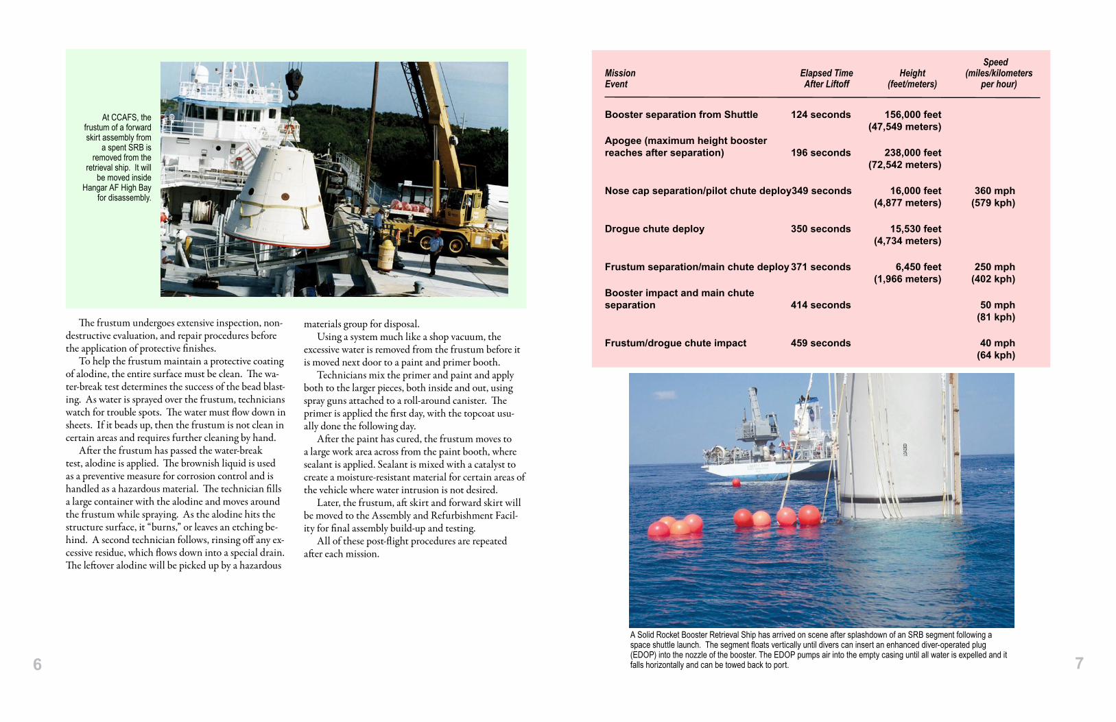
SpeedMission ElapsedTime Height (miles/kilometersEvent AfterLiftoff (feet/meters) perhour)
Booster separation from Shuttle 124 seconds 156,000 feet (47,549 meters)Apogee (maximum height boosterreaches after separation) 196 seconds 238,000 feet (72,542 meters)
Nose cap separation/pilot chute deploy 349 seconds 16,000 feet 360 mph (4,877 meters) (579 kph)
Drogue chute deploy 350 seconds 15,530 feet (4,734 meters)
Frustum separation/main chute deploy 371 seconds 6,450 feet 250 mph (1,966 meters) (402 kph)Booster impact and main chuteseparation 414 seconds 50 mph (81 kph)
Frustum/drogue chute impact 459 seconds 40 mph (64 kph)
A Solid Rocket Booster Retrieval Ship has arrived on scene after splashdown of an SRB segment following a space shuttle launch. The segment floats vertically until divers can insert an enhanced diver-operated plug (EDOP) into the nozzle of the booster. The EDOP pumps air into the empty casing until all water is expelled and it falls horizontally and can be towed back to port.

Captions, front page:
(Top) The solid rocket boosters on Space Shuttle Discovery spew a column of flame as it races toward space on mission STS-105 to the International Space Station. The twin sets of boosters provide 80 percent of the space shuttle launch thrust. Approximately 2 minutes after launch, the boosters will be jettisoned into the Atlantic Ocean and recovered for future use.
(Middle) The SRB Retrieval Ship Liberty Star maneuvers a spent booster toward the Hangar AF wharf at CCAFS so its SRB can be in line with the hoisting slip. A 200-ton, straddle lift crane lifts the booster above the water and all remaining saltwater contamination is washed off.
(Bottom) The individual segments are transferred to a railhead located on the launch side at Kennedy Space Center. A train backs up and the segment is lowered onto a rail car. Yellow transportation covers are placed over each segment and secured. The covered segments are moved to J and J Railroad, where they are hooked up to yet another train for the long trip back to Utah.
National Aeronautics and Space Administration
Kennedy Space Center, FL
www.nasa.gov
FS-2004-07-012-KSC (Rev. 2006)
NA
SA
Fact
s
8