Solar sailor project report newest rev
69
June 2011 Solar Sailor Interactive Educational Game DRAFT – Revision 2B Project Report Project Report Interactive Educational Game Prepared by: Victor Arosemena, William McNally, Anthony Santistevan, Jeremy Struebing, Taylor DeIaco, Joe Rodriguez, Loren Karl Schwappach and Noemi Reyes Wikstrom. EE490 – EE491 Product Design Series Capstone Project Team DRAFT – Revision 2B Creative Solutions Team LLC Colorado Technical University 4435 N. Chestnut Street Colorado Springs, CO 80907 Accepted by: Professor Dr. Kathy Kasley Department of Computer and Electrical Engineering Colorado Technical University June 2011
-
Upload
loren-schwappach -
Category
Business
-
view
8.258 -
download
5
Transcript of Solar sailor project report newest rev

June 2011 Solar Sailor Interactive Educational Game DRAFT – Revision 2B Project Report
Project Report
Interactive Educational Game
Prepared by:
Victor Arosemena, William McNally, Anthony Santistevan, Jeremy Struebing,
Taylor DeIaco, Joe Rodriguez, Loren Karl Schwappach and Noemi Reyes Wikstrom.
EE490 – EE491 Product Design Series
Capstone Project Team
DRAFT – Revision 2B
Creative Solutions Team LLC Colorado Technical University
4435 N. Chestnut Street
Colorado Springs, CO 80907
Accepted by:
Professor Dr. Kathy Kasley
Department of Computer and Electrical Engineering
Colorado Technical University
June 2011

June 2011 Solar Sailor Interactive Educational Game DRAFT – Revision 2B Project Report
2 | P a g e
CREATIVE SOLUTIONS DESIGN TEAM
Victor Arosemena Senior Undergraduate Electrical Engineer
Taylor DeIaco Junior Undergraduate Electrical Engineer
William McNally Senior Undergraduate Computer Engineer
Joe Rodriguez Junior Undergraduate Electrical Engineer
Anthony Santistevan Senior Undergraduate Electrical Engineer
Loren Schwappach Senior Undergraduate Computer/Electrical Engineer
Jeremy Struebing Junior Undergraduate Electrical Engineer
Noemi R. Wikstrom Senior Undergraduate Electrical Engineer

June 2011 Solar Sailor Interactive Educational Game DRAFT – Revision 2B Project Report
3 | P a g e
RECORD OF REVISION
Revision Description Name Date
1A Drafted Volume I. Changes EE490 Report NRW 05/07/2011
1B Correction on Grammar Errors WM 05/20/2011
1B Adding Information and Format NRW 05/24/2011
1C Entered frame & Air flow system descriptions/figures
from previous. Updated figure reference numbers.
VA 05/24/2011
1C User‟s Demographics NRW 05/25/2011
1D Add Instructions in Spanish NRW 05/26/2011
2A Editing of the Report NRW 06/10/2011
2B Editing of Report added information on Power
Distribution/Play Surface/Air Flow System/Home
Base/Power Systems/Graphics.
LKS 06/16/2011

June 2011 Solar Sailor Interactive Educational Game DRAFT – Revision 2B Project Report
4 | P a g e
ACKNOWLEDGMENTS
The Creative Solutions Team, LLC would like to acknowledge and extend a heartfelt gratitude to
the following persons and companies who have made the completion of the Solar Sailor
Interactive Educational Game possible:
Our Dean, Dr. Kathy Kasley, for her vital encouragement, guidance and support.
All Colorado Technical University, Department of IT and Computer and Electrical Engineering
faculty members and Staff.
To Mrs. Deborah Thornton from the Kennedy Imagination Celebration Center, for the inspiration
she extended.
To Mr. Barry Farley from the Chimaera Group for his contribution and creative inspiration in the
design of the backdrop board.
To Mr. Mike Studebaker from Anthony‟s Manufacturing service for his amazing craftsmanship
and precious time dedicated in the construction of the Solar Sailor‟s metal frame.
To Anthony Sharer for the printing of the Informational display, Backdrop display and User
Interface displays.
To Scott Phelps for his contribution on the design and construction of the plastic resin molding
and materials of the Shuttle for the Solar Sailor Project.
To Michaela Schwappach for her cheerful disposition and constant reminder of our primary
customer, the Children of Colorado Springs.
To Frank VLcek for allowed us the use of his tools in the construction of the Solar Sailor IEG.
To Analog Devices for donating the ADuC7026 microcontroller unit, vital to the communication
system of the Solar Sailor IEG.
A very special thank you to one our own team members, Mr. William McNally for sharing his
knowledge and experience with all of us.
Most especially to our family and friends.
And to God, who made all things possible.

June 2011 Solar Sailor Interactive Educational Game DRAFT – Revision 2B Project Report
5 | P a g e
ABSTRACT
The Solar Sailor Interactive Educational Game project report provides the game definition,
block diagram with interfaces and individual components design details, operating instructions,
testing, costs and trade-offs.
This includes:
User Interface
Acceptance Testing Checklist
Safety Concerns
Components and Connections
Design Trade-Offs
Conclusion
June 2011 Solar Sailor Interactive Educational Game DRAFT – Revision 2B Project Report
6 | P a g e
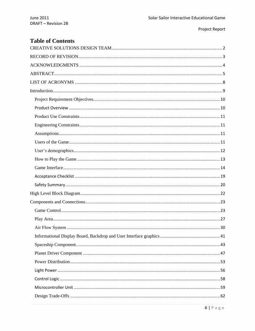
Table of Contents
CREATIVE SOLUTIONS DESIGN TEAM ................................................................................................ 2
RECORD OF REVISION ............................................................................................................................. 3
ACKNOWLEDGMENTS ............................................................................................................................ 4
ABSTRACT .................................................................................................................................................. 5
LIST OF ACRONYMS ................................................................................................................................ 8
Introduction ................................................................................................................................................... 9
Project Requirement Objectives.............................................................................................................. 10
Product Overview ................................................................................................................................... 10
Product Use Constraints .......................................................................................................................... 11
Engineering Constraints .......................................................................................................................... 11
Assumptions ............................................................................................................................................ 11
Users of the Game ................................................................................................................................... 11
User‟s demographics ............................................................................................................................... 12
How to Play the Game ............................................................................................................................ 13
Game Interface ........................................................................................................................................ 14
Acceptance Checklist .............................................................................................................................. 19
Safety Summary ...................................................................................................................................... 20
High Level Block Diagram ......................................................................................................................... 22
Components and Connections ..................................................................................................................... 23
Game Control .......................................................................................................................................... 23
Play Area ................................................................................................................................................. 27
Air Flow System ..................................................................................................................................... 30
Informational Display Board, Backdrop and User Interface graphics .................................................... 41
Spaceship Component ............................................................................................................................. 43
Planet Driver Component ....................................................................................................................... 47
Power Distribution .................................................................................................................................. 53
Light Power ............................................................................................................................................. 56
Control Logic ........................................................................................................................................... 58
Microcontroller Unit ............................................................................................................................... 59
Design Trade-Offs .................................................................................................................................. 62

June 2011 Solar Sailor Interactive Educational Game DRAFT – Revision 2B Project Report
7 | P a g e
Design Cycle ............................................................................................................................................... 63
CONCLUSION ............................................................................................................................................... 66

June 2011 Solar Sailor Interactive Educational Game DRAFT – Revision 2B Project Report
8 | P a g e
LIST OF ACRONYMS
Acronym Definition of Term
AFS Air Flow System
ARS Air Return System
AWG American Wire Gage
CFM Cubic Feet per Minute
CPSC Consumer Product Safety Commission
EDS Electrostatic Discharge Sensitive
IEG Interactive Educational Game
LCD Liquid Crystal Display
LED Light-Emitting Diode
MCU Microcontroller
NEC National Electric Code
PWM Pulse-width Modulation
RF Radio Frequency
RPM Revolutions Per Minute
SS Solar Sailor
SSE Solar Sailor Explorer
STEAM Science, Technology, Engineering, Art, and Mathematics
UI User Interface

June 2011 Solar Sailor Interactive Educational Game DRAFT – Revision 2B Project Report
9 | P a g e
Introduction
The Creative Solutions Team has designed an educational, interactive, astronomy game
whose purpose is to teach children about the solar system and orbital mechanics. The Solar
Sailor is designed to expose the player to some aspects of the science behind space travel. The
objective of this project report is to provide a detail account of the design process and
construction of the Solar Sailor Interactive Educational Game. The final product will be donated
to the Kennedy Center Imagination Celebration. The Kennedy Center Imagination Celebration is
an independent foundation that serves the community by providing arts, science and educational
programs to children in the Pikes Peak Region.
Figure 1: Solar Sailor Features

June 2011 Solar Sailor Interactive Educational Game DRAFT – Revision 2B Project Report
10 | P a g e
Figure 1 Solar Sailor Features
1 User Interface Panel
2 Mission Select Button and Indicator Panel
3 Success and Failure Indicators
4 Home base
5 Shuttle
6 Rotating Planet
7 Game Play Surface
8 Air Return Rails
9 Creative Backdrop
10 Power Lights
11 Clear Windows (on both sides)
Table 1: Solar Sailor Features as depicted on Figure 1.
Project Requirement Objectives
The primary objectives for the Solar Sailor include:
Demonstrate the concept of frictionless space.
Provide an interactive learning tool for engaging astronomical information.
Exhibit the mechanics involved in space vehicle thrust.
Teach children the importance of fuel conservation in space exploration.
Present the physics of planetary motion around a solar body.
Product Overview
The Solar Sailor interactive game is design to be played as an enclosed system contained
within approximately 8 ft. high by 4 ft. 10 inches wide by 4 ft. 6 inches long table. Within these
dimensions the system can be broken up into three primary levels. The top of the Solar Sailor
system will be contained within a transparent Plexiglas cover and overhead lighting system. The
first level of the system contains the play field of the table. This level contains two objects, a
central model sun and an orbiting planet. The planet will rotate around the playfield in a circular
solar orbit at various speeds determined by the player selected planetary mission. This motion is
achieved via a mechanical arm connected to the central sun and controlled by a game controller.
An air propelled rover (spaceship) will be navigated by the user over a table similar to air
hockey game (demonstrating frictionless space). The player will be given a mission to visit one
of the eight planetary bodies in our solar system. The player will then proceed to navigate the air
propelled space ship using a limited amount of fuel (represented by time) to the planet. If the

June 2011 Solar Sailor Interactive Educational Game DRAFT – Revision 2B Project Report
11 | P a g e
spaceship reaches the planet, then the planet will flash/illuminate and an LCD will display
planetary facts, the distance covered, and amount of fuel used. Thereafter the LCD will provide
the player with their next planetary mission after positioning the spaceship back at home base. If
the player fails to reach the planet (runs out of fuel) the LCD will inform the user of the mission
failure and reset the system for the next attempt.
Product Use Constraints
The SS shall require AC power and should be located within 3 feet of a 110 volts electric
receptacle. The game shall be contained within a large table with a locked removable side
opening for service and repair. To ensure the safety of the users, no individual is allowed to
touch the internal components of the system without a thorough understanding of the electrical
and mechanical components of the design.
Engineering Constraints
The complete cost for the project shall not exceed the amount of $800.00 USD. The
actual cost of the project is $1634.45 approved by the costumer. (See Appendix/Part Lists) The
design shall be light enough for transportation, no more than 200 pounds. The design shall be as
robust and reliable as possible, since no maintenance will be provided by the Creative Solutions
team after the completion of the project. The life expectancy of all components of the design
shall be greater than 3 years without maintenance.
Assumptions
Product assumptions for the SS system include: Users are a minimum of 3 feet 6 inches
in height. (See Appendix/Height Chart) The SS will be contained within the Imagination
Celebration at the Citadel Mall in a conditioned indoor environment with standard temperature,
humidity, and air quality. The SS will be provided a local conditioned 120VAC power source.
The SS will sits on a flat, level floor.
Users of the Game
The Solar Sailor is intended to be played by children from the ages of six to twelve years old, but
it can be challenging to all ages. The game is designed to provide visual clues and auditory references
throughout the game to assist younger players in navigating the Shuttle for successful mission
completion. Adult supervision is required for children 8 years and younger; in compliance with the
Consumer Product Safety Commission (http://www.cpsc.gov). Users should be no less than 3‟6‟‟ in
height to reach the User Interface control panel. A first grade reading level or higher is suggested for

June 2011 Solar Sailor Interactive Educational Game DRAFT – Revision 2B Project Report
12 | P a g e
understanding the information provided via the Solar Sailor informational display and additional
information covered on the informational display board (backdrop poster board). The user will require
motor skills as necessary to operate the joystick, and select one of the planetary missions.
User’s demographics
Edited by Noemi Wikstrom
As part of the design process is necessary to research the product‟s target audience. The
game is designed to fulfill the needs of our primary customer. As stated before, the Solar Sailor
is an Interactive Educational Game. The Solar Sailor game target audience is children ages six to
twelve years old in the Pikes Peak Region who visits the Imagination Celebration Center.
One of the major concerns in the design on the Solar Sailor was to provide a console that
will be ergonomically efficient for our target audience. The average height of 6 year old child is
3 feet six inches (see Appendix/ Growth Chart). The Creative Solutions team designed the
Control Panel for the Solar Sailor Game slanted downwards in a 45 degree angle thus making the
joystick, the mission select buttons and the LCD available to the user. Safety measures and
considerations in the design process will be discussed further in this publication under the Safety
Summary Section.
In a study conducted by the Consumer Product Safety Commission relating to
children‟s age to toy characteristics and play behavior it shows that computer and interactive
educational games for children on the age group six to eight years old are increasingly
sophisticated. These children can use a joystick to move objects, and can use both
navigational systems and exploratory programs and are very attracted to console and hand
held scientific games.
Children from ages ranging from 9 to 12 years old are interested in complex games
with complex subjects, music creation games, and educational games like multimedia
activities. They enjoy games based on popular sports and activities, like skating and complex
fantasy games. This age group depending on their experience can have very sophisticated
computer skills. Children play with audiovisual equipment at different ages. The volume
level, length of the game, visual images, language presentation and content/theme
represented in the game determines the age for which the game is appropriate. [38]
The Creative Solutions team took the above criteria in consideration when designing
the Solar Sailor game. The Solar Sailor provides an educational aspect at the inclusion of
planetary and physics facts in addition offer the experience of maneuvering a space shuttle in
a frictionless environment. All of these aspects are related to the Science of Astronomy.
Another aspect of our research led us to the inclusion Spanish instructions in the game console.
According with the U.S. Census Bureau 12% of the population in Colorado Springs is Hispanic
or Latino origin. (http://quickfacts.census.gov/qfd/states/08/0816000.html) The users of the Solar
June 2011 Solar Sailor Interactive Educational Game DRAFT – Revision 2B Project Report
13 | P a g e
Sailor game will have the opportunity to listen to the instructions in English or Spanish. Audio
instructions are included to reinforce and ease the experience of our younger players.
How to Play the Game
Lead Engineer: Taylor DeIaco, Alternate Bill McNally. Audio recorded by Noemi Wikstrom and
Loren Schwappach. Instructions and Editing by Noemi Wikstrom.
Goal of the Game
The player must navigate the Solar Sailor Shuttle from home base using the joystick and
land the Shuttle near the mission selected rotating planet before exhausting their limited fuel
supply.
Contents of the Game
A Playfield
A sun replica
A rotating planet
A RF Controlled Shuttle
Joystick
Fuel gauge
Informational Display
Start/Reset Buttons
Mission Selection buttons
Game Instructions
Informational Display Board (Back drop poster board)
Game Instructions
1. Press START button to begin
2. Select a mission by pressing the button of your chosen planetary destination.
3. Wait for the countdown to complete.
4. Use the joystick to rotate and propel your Solar Sailor Shuttle to the planet.
5. Monitor the Fuel Gauge.
6. Try to land on the Planet
7. Do not run out of fuel.

June 2011 Solar Sailor Interactive Educational Game DRAFT – Revision 2B Project Report
14 | P a g e
Game Interface
The user will be provided visual instructions written in English and Spanish displayed on the User
Interface and on the LCD. The user will also be presented with audio instructions recorded by Noemi
Wikstrom (Spanish) and Loren Schwappach (English). After the user finishes reading/hearing the initial
instruction the user will then initiate the game by pressing Start as currently being prompted by the audio
and LCD:
“SOLAR SAILOR PRESS START TO BEGIN”
Spanish: “EXPLORADOR SOLAR PRESSIONE EL BOTON DE INICIO”
Auditory clue: Press Start to continue. (Pause, 30 seconds, message repeats)
Spanish: Presione el botón de inicio para continuar.
The start button will be pressed which will display the following on the LCD:
“SELECT MISSION WITH MISSION SELECT BUTTONS”
Spanish: “SELECCIONE LA MISION UTILIZANDO LOS BOTONES DE SELECTION
PLANETARIA”
Auditory clue: Select the Mission using the Mission Select Buttons in the Control
Panel. The Mission Select Buttons are located in the right hand side of the Control
Panel indicating the planet‟s name: Mercury, Venus, Earth, Mars, Jupiter, Saturn,
Uranus and Neptune.
Seleccione la misión utilizando los botones de selección planetaria. Los botones
de selección planetaria están localizados a la mano derecha de panel de controles
indicando el nombre de los planetas: Mercurio, Venus, Planeta Tierra, Martes,
Júpiter, Saturno, Urano y Neptuno.
Once the user selects the mission, as the menu states, the overhead lighting will turn on
and the air table will be activated levitating the shuttle and simulating frictionless space. The
planet motor will also begin to drive the planet at the appropriate speed as determined by the
player selected mission. The RF communication system will allow the shuttle to communicate
with the game controller to provide future control to the user. A blastoff countdown timer will
then be displayed on the informational display to prepare the user for blast-off and user control.
The user will not have control of the Shuttle until the blastoff countdown timer reaches zero.
LCD will display a graphic indicating a 10 – 0 countdown:

June 2011 Solar Sailor Interactive Educational Game DRAFT – Revision 2B Project Report
15 | P a g e
Auditory clue: Beginning of Blast off, all stations ready: (Pause 3 seconds) 10, 9,
8, 7, 6, 5, 4, 3, 2, 1, 0.
Comienzo de cuenta regresiva. (Pausa de 3 segundos) Diez, nueve, ocho, siete,
seis, cinco, cuatro, tres. dos, uno, zero.
Once the blast off countdown timer reaches zero the LCD will display:
“BLAST OFF!
Auditory Clue: BLAST OFF!
DESPEGUE!
The fuel gauge will then show full and the user will be able to use the joystick to
navigate/control the shuttle.
The LCD will display the following message:
FUEL GAUGE – FULL
Auditory Clue: Monitor the Fuel Gauge. Use the propulsion system carefully,
you have limited amount of fuel to reach the planet. Each time you move the
joystick, the fuel will be depleted. Plan your mission accordingly.
Observe la válvula de combustible. Use el sistema de propulsión
cuidadosamente, solo tiene una cantidad limitada de combustible para alcanzar el
planeta. Cada vez que mueva la palanca de control agotara los niveles de
combustible. Calcule la misión en respecto de los niveles de combustible
disponible.
The user will control the shuttle with the directional joystick. Pressing forward or reverse
will thrust the shuttle forward or backward using the shuttles fan system. Pressing left and right
will rotate the shuttle around its middle axis. Whenever the user thrusts the shuttle, the shuttle
fuel indicator will deplete according to how long the fans are used.
LCD will display the following message:
“USE THE JOYSTICK TO ROTATE AND PROPEL YOUR SOLAR SAILOR
SHUTTLE TO THE PLANET”
“UTILICE LA PALANCA DE CONTROL PARA HACER GIRAR Y ACELERAR LA
NAVE ESPACIAL HACIA EL PLANETA”

June 2011 Solar Sailor Interactive Educational Game DRAFT – Revision 2B Project Report
16 | P a g e
Auditory Clue: USE THE JOYSTICK TO ROTATE AND PROPEL YOUR SOLAR
SAILOR SHUTTLE TO THE PLANET. Push up to propel the shuttle in a forward
movement. Push left to rotate the shuttle in a clockwise movement. Push right to rotate
the shuttle in a counterclockwise movement. Push down to propel the shuttle backwards.
Utilice la palanca de control para hacer girar y acelerar la nave especial hacia el planeta.
Presione hacia arriba para mover la nave espacial en movimiento directo. Presione hacia
la derecha para mover la nave espacial en movimiento lateral Este. Presione hacia la
izquierda para mover la nave espacial en movimiento lateral Oeste. Presione hacia abajo
para mover la nave espacial en movimiento reverso.
The player will maneuver the shuttle to the outside edge of the rotating planet in order to
“dock” or “land” on the planet.
LCD will display the following message:
“TRY TO LAND ON THE PLANET”
“TRATE ALCANZAR EL PLANETA”
Auditory Clue: Try to land on the Planet. The shuttle should hover closely to the planet
for at least 5 seconds.
Trate de alcanzar el planeta. La nave espacial deberá aterrizar cerca del planeta por al
menos 5 segundos.
If the shuttle docks on the planet, before the shuttle fuel is depleted, this indicates a
successful mission. The user will be congratulated with flashing lights and a message from an
LED on the Control Panel:
“CONGRATULATIONS! PLANET REACHED. MISSION SUCCESS!”
“FELICITACIONES! HA ATERRIZADO EN EL PLANETA. LA MISION EXITOSA!
<<PAUSE>>
Auditory Clue: Congratulations! You have completed the mission. (Music will play
for 30 seconds)
Felicitaciones, usted ha completado la misión.
This will initiate a reset for a new game to be played.

June 2011 Solar Sailor Interactive Educational Game DRAFT – Revision 2B Project Report
17 | P a g e
If the fuel is fully depleted before the shuttle lands on the planet, the mission is failed. A
failure notification will be displayed on the Control Panel:
“MISSION FAILED. TRY AGAIN”
MISION FALLIDA. TRATE DE NUEVO.
<<PAUSE>>
Auditory Clue: Mission Failed. Please try again. (Music will play for 30 seconds)
Misión Fallida. Por favor trate de nuevo.
Upon the fuel being exhausted the air system and lights will turn for a period of 30
seconds. This will give the player the illusion of being stranded in space. After the 30 second
timer has expired the game will enter the shuttle return mode. The air system and lights will
again turn on and also the shuttle return air system will also be enabled. The system will stay in
this mode till the shuttle arrives at the home port tripping the magnetic sensor and returning the
game to its idle state.
Figure 1: User Interface Panel
The user interface is shown in Figure 1 above. The LCD display will output various directives to
help the user play the game. Number 2, is the fuel gauge, which displays the remaining fuel for the
shuttle. Number 3 shows the joystick which is used to direct the shuttle in the four directions. Finally,
the Start and Reset button are self explanatory.
Figure 2: Solar Sailor user interface panel.

June 2011 Solar Sailor Interactive Educational Game DRAFT – Revision 2B Project Report
18 | P a g e
Figure 3: Solar Sailor play surface.
On the play field a fan propelled shuttle (puck) will be levitated during play by an air hockey like
table design. The air table is used by the Solar Sailor to simulate a frictionless surface. The player will
select a mission via the control panel display (Figure 2) using the mission selection buttons (Figure 1
item 2). The player will have a limited amount of fuel available to reach their chosen planetary
destination, and this limit will be indicated by the 'fuel gauge' display located on the control panel
(Figure 1 part 4). If the Shuttle is successfully navigated by the user to the planet (before running out of
fuel), a magnetic sensor on the rotating planet will transmits a mission success message to the game
controller, and an LED on the far end of the playfield will illuminate indicating a green “Congratulations
– Mission Complete” if the mission was successful or a red “Mission Failure” LED if the mission was
unsuccessful.
The informational display will also display facts to the player about the completed mission. Once
either mission success or failure is detected the simulation will pause (the planet will stop rotating, the
Shuttle will no longer be levitated, and the primary lighting will turn off) to allow the user to take in
mission success/failure. After a set amount of time the system will then reset by initiating directional
airflow to return the Shuttle to home base. The system will then provide the player the option to select
their next planetary mission. The active/inactive players will also have an informational display board
located behind the Solar Sailor game relative to the control panel. This display will be approximately 3
feet height by 6 feet wide. On this informational display board will be accurate information and pictures
of the various Solar Sailor planetary missions to include astronomical information, physics equations and
relative size and distances of each body from the sun as well as relevant information/equations pertaining
to the concepts used in the Solar Sailor system game.

June 2011 Solar Sailor Interactive Educational Game DRAFT – Revision 2B Project Report
19 | P a g e
Acceptance Checklist
Item Criteria Verifications Fail Pass
1.0 Solar Sailor system
turns on
The game is connected to the power source
1.1 Informational display
turns on
Informational Display (LCD) shows message
“Solar Sailor Press Start to begin”
2.0 Start Button functional Game is waiting to start
ON = Start
Idle = Reset (approximately 2 minutes of inactivity)
2.1 Mission Selection
Buttons Functional
Press each Planetary Mission
Rotating Planet will move, the speed depending
upon the selection.
2.2 Shuttle is functional Using the joystick, the shuttle moves back, forward,
counterclockwise and clockwise.
Mission Complete – Shuttle Reach Planet
Mission Failure – Shuttle remains inactive for more
than 2 minutes
Mission Failure – Shuttle navigates until fuel is
exhausted.
2.3 Planet Driver
Functional
Planet Driver moves at selected speed
Planet Driver Stops when Shuttle Reach the planet
Planet Driver Stops when game is Idle (after two
minutes of inactivity)
2.4 Joystick is functional Joystick inactive until countdown reaches zero
Shuttle moves forward, backwards, clockwise and
counterclockwise
2.5 Fuel Gauge Functional LEDs show fuel when game starts
LEDs decrease after joystick is moved
LEDs show fuel empty after joystick is moved a
maximum of 15 times
3.0 Playfield Functional Shuttle Lifts up when air compressor turns on
Shuttle returns to home base when side fans turns on
Air compressor turns off when game is on idle
mode.
Air Compressor turns on, when game starts
Air Compressor turns off, when mission fails
4.0 Control Panel
Functional
Informational Display provides instructions to the
player
Informational Display prompt player to press start
Informational Display shows countdown
Informational Display provide player with planetary
facts
Mission Complete LED turns on
Mission Failed LED turns on

June 2011 Solar Sailor Interactive Educational Game DRAFT – Revision 2B Project Report
20 | P a g e
Safety Summary Edited by: Noemi Wikstrom, Safety Labels engineered/added by: Loren Schwappach
The primary consideration for safety in the design of the Solar Sailor is to assure that the
use of the interactive game does not cause injury to the user. Creative Solutions also
acknowledge that safety can also extend beyond human injury to include property damage and
environmental damage. Therefore; the Creative Solutions teams have also consider the issues of
safety in design because of liability arising from the use of an unsafe product. Liability refers to
the manufacturer of a machine or product being liable, or financially responsible, for any injury
or damage resulting from the use of an unsafe product. [2] To assure that the Solar Sailor
Interactive game will not cause injury or loss, the Creative Solutions Team design safety into the
product. Each component and section in this report will include the safety considerations and
measures taken by the designers to provide a safe product to our customers.
The Solar Sailor Game was designed as enclosed system due to safety considerations.
The primary target audience of the product is children. By making the moving parts, electrical
components and small components inaccessible to the user, the Solar Sailor prevents electrical
hazards, shocking hazards and potential damage to the equipment. Enclosing the system also
provides durability to the components of the game.
Another important safety feature of the Solar Sailor Game is the tampered switch added
to the back panel. The purpose of the tampered switch is to shut-off all power to the game once
the utility door on the side of the game is open. The utility door provides access to internal
components such as the MCU and the Air Compressor.
As an extra safety measure Warning, Caution and Note labels are also included on the
Solar Sailor Game. The safety labels include labels informing the user to remove power before
opening the access panel, warning the user not to touch the hot air ventilation system near the
lights, informing the user of the systems weight and that multiple people are required to lift /
remove the top, and informing the user of the risk of electric shock, high current devices and
power warnings both inside the system and outside.
The following are general safety precautions that are not related to any specific procedure
and therefore do not appear elsewhere in this publication. The safety recommendations must be
followed during the operations and maintenance of the Solar Sailor IEG. [3]
Electrical Precautions
Safety regulations must be observed at all times. Under certain conditions, dangerous
potentials may exist in circuits with power control in the OFF position because of the charges
retained by capacitors. To avoid casualties, before touching circuits, always remove power,
discharge, and ground the circuits. Under no circumstances should any person reach within or

June 2011 Solar Sailor Interactive Educational Game DRAFT – Revision 2B Project Report
21 | P a g e
enter an enclosure for the purpose of servicing or adjusting the equipment without the presence
or assistance of another person capable of rendering aid.
Notes, Cautions, and Warnings
The following warnings and cautions appear in the text of the Project Report and repeated
here for emphasis.
Ensure that all systems are grounded to prevent electrical shock.
Ensure that all electrical circuits are de-energized.
The printed circuit boards contain Electrostatic Discharge Sensitive (EDS) devices.
Improper board handling could result in damage of the board. The following precautions are
recommended when handling the board:
Make sure you are grounded electrically by using a wrist strap connected to an
electrically grounded component or physically touching the chassis or something
electrically connected to the chassis. Any movement can generate a damaging
static voltage. Additional discharging to a known ground may be needed after
movement.
Handle circuit boards by the edge only. Do not touch the printed circuitry or the
connector pins on the circuit cards.
Notes, Cautions, and Warnings are applied under the conditions described below:
Note
A NOTE statement is used to notify people of installation, operations, programming, or
maintenance information that are important, but not hazard-related.
Caution
CAUTION indicated a potentially hazardous situation which, if not avoided, could result
in minor or moderate injury. It may also be used to alert against unsafe practices.
Warning
WARNING indicates potentially hazardous situation which, if not avoided, could result
in death or serious injury.
For a detailed explanation and further safety considerations please refer to the User
Manual and Safety Instructions in the Appendix section.

June 2011 Solar Sailor Interactive Educational Game DRAFT – Revision 2B Project Report
22 | P a g e
Tamper Switch
Lead Engineers and Designers: William McNally and Noemi Wikstrom, Installed by: Loren
Schwappach
End switches or tamper switch are typically wired to a component serving as an open/not
open indicator. When the tamper is powered open, one of the tamper blades makes contact with
the spring rod of the end of the switch which in turn makes a connection allowing power to flow
to the Solar Sailor. This set up is used as a safety precaution, to ensure that all components of the
game are powered off when the access panel is open during maintenance or servicing of the
game. The following figure shows the tamper switch component in the lower back panel of the
Solar Sailor.
Figure S1: Tamper Switch
High Level Block Diagram Created by: Loren Schwappach, Edited by: Noemi Wikstrom
The Solar Sailor will have several hardware components that will directly interact with
the MCU. The microcontroller will provide commands to turn on and off the air table, lights, and
return fans, and directives to adjust the speed and sensors to indicate when the spaceship has
reached its destination (home base or planet). Each sensor has a specific purpose in the overall
design mainly to define the states that will enable and reset the condition of the main controller.
June 2011 Solar Sailor Interactive Educational Game DRAFT – Revision 2B Project Report
23 | P a g e
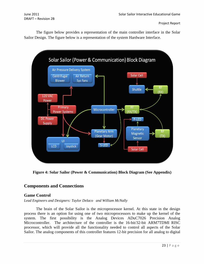
The figure below provides a representation of the main controller interface in the Solar
Sailor Design. The figure below is a representation of the system Hardware Interface.
Figure 4: Solar Sailor (Power & Communication) Block Diagram (See Appendix)
Components and Connections
Game Control
Lead Engineers and Designers: Taylor DeIaco and William McNally
The brain of the Solar Sailor is the microprocessor kernel. At this state in the design
process there is an option for using one of two microprocessors to make up the kernel of the
system. The first possibility is the Analog Devices ADuC7026 Precision Analog
Microcontroller. The architecture of the controller is the 16-bit/32-bit ARM7TDMI RISC
processor, which will provide all the functionality needed to control all aspects of the Solar
Sailor. The analog components of this controller features 12-bit precision for all analog to digital

June 2011 Solar Sailor Interactive Educational Game DRAFT – Revision 2B Project Report
24 | P a g e
(ADC) and digital to analog (DAC) conversions. The controller provides up to 16 input ADC
channels or 12 input ADC channels and four DAC output channels. [5]
The second microprocessor under consideration is the Atmel ATMega24, the big brother
to the ATiny24 which will be the microprocessor on the puck receiving the transmitted signal
from the main processor. Experimentation is scheduled as one of the first design validation steps
upon the receipt of the hardware that will be ordered upon the approval of the initial design
concept. Regardless of the actual processor chosen, the requirements of the design are consistent.
The software control as shown in Figure 4 will be the operation of the communication between
the controller kernel and the entire game system.
The input into the system will be received from the user interface. Each input signal will
be passed through a second-order low pass filter to eliminate signal switch bounce from being
introduced into the processor kernel. All processes instantiated by the microprocessor will be
interrupt driven. They will be separated into two operations, game mode and non-game mode. As
shown in Figure 1, the first operation after the initial power up routines is to ensure that the puck
is in its home position. If the puck is not in the home position will automatically launch the puck
return system. Once system has determined that the puck is home the system will enter an idle
state waiting from input from the user. Standard messages will be displayed to the LCD interface
upon entering the game mode.
Once a game mode instance has been initiated and the welcoming text has been
presented, the mission statistics will be displayed. This state will allow the user to select from all
the possible missions available. Revision one of the Solar Sailor will incorporate the planet
characteristics of solar system that Earth is a member of, later revisions will have the opportunity
of modifying these parameters to simulate other solar systems around the universe. Once the
user accepts the displayed mission, the mission parameters will be loaded into the instantiation of
the game class. The communication channels between the processor kernel and the puck, and the
processor and the planet will be initiated. The blower motor will be enabled and the game will
wait for the planet rotation to come up to speed.
June 2011 Solar Sailor Interactive Educational Game DRAFT – Revision 2B Project Report
25 | P a g e
Internal Diagnostics
Check Home Proximity Sensor
Puck at Home Position?
Initiate Return System
Initialize Power
No
Idle Mode
Yes
Interrupt Received
No
Display Welcome Message
Yes
Display Mission Stats
Accept Mission?
Increment Mission Counter
No
Initialize Mission Parameters
Yes
Initialize Drive Motor
Start Blower Motor
Wait for Start Button
Start Button Pressed
No
Wait for Joy Stick
Yes
Joy Stick True
Drive Motor
Yes
Joy Stick False
Halt Motor
Yes
Check Fuel Status Fuel Exhausted?
Yes
Planet Reached
No
No
Game Over
Yes
Return to Idle Mode
No
No
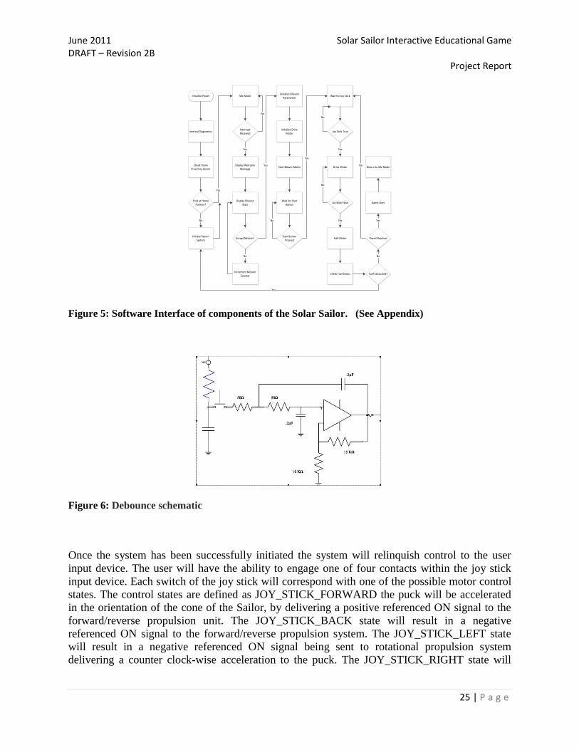
Figure 5: Software Interface of components of the Solar Sailor. (See Appendix)
Figure 6: Debounce schematic
Once the system has been successfully initiated the system will relinquish control to the user
input device. The user will have the ability to engage one of four contacts within the joy stick
input device. Each switch of the joy stick will correspond with one of the possible motor control
states. The control states are defined as JOY_STICK_FORWARD the puck will be accelerated
in the orientation of the cone of the Sailor, by delivering a positive referenced ON signal to the
forward/reverse propulsion unit. The JOY_STICK_BACK state will result in a negative
referenced ON signal to the forward/reverse propulsion system. The JOY_STICK_LEFT state
will result in a negative referenced ON signal being sent to rotational propulsion system
delivering a counter clock-wise acceleration to the puck. The JOY_STICK_RIGHT state will

June 2011 Solar Sailor Interactive Educational Game DRAFT – Revision 2B Project Report
26 | P a g e
result in a positive referenced ON signal being delivered to the rotational propulsion system
delivering a clock-wise acceleration to the puck.
Upon the release of any joy stick movement the propulsion systems will terminate and the
calculated fuel, or propulsion time remaining, will be updated for the interactive statistics
provided to the user via the LCD display. The system will monitor the fuel level through
iterations of the propulsion sequence until exhausted. If the fuel is exhausted before the mission
is accomplished the system will exit game mode and initiate the puck return sequence. If the
planet is encountered the system will initiate GAME_LEVEL_SUCCESS mode and the next
level of difficulty will be presented to the user for their acceptance.
At any time during any game mode there has been no user input detected for more than 45
seconds, game mode will terminate shutting down the blower system. After 15 minutes of no
user input the system will enter sleep mode.
Parts required for the MCU and Software design:
4 – Switch, PB, SPST, On/Off, Red
1 – LCD Display Parallel
1 – Joystick
1 – ARV Dragon (Software)
1 – Amp 20 – Position, 2-Row Straight Breakaway Header Connector
1 – AMP 40 –Position, 2-Row Straight Breakaway Header Connector
1 ARES 40-Pin ZIF Socket
1 – Precision Analog Microcontroller 12 Analog I/O ARM7TDMI MCU
1 – Low Voltage Octal Bidirectional Transceiver
16 – 47 Ω +/- 10% resistor
20 - .2µF 100V 5% Capacitor
8 - 10KΩ resistor +/- 5%
5 – Op-Amp
2 - Adapter for standard 80 pin TQFP SMD Parts
2 - 20-pin SSOP Adapter
2 - Versa Strip Phenolic Prototype Board
1 - Stand-off Hex M/F .875" 6-32BR
100 - Phillips Machine Screw 6-32-1/2
100 - Washer Flat #6
100 - Washer Lock Internal Teeth #6 Zinc
100 - Nut Hex 6-32 Zinc
2 - ATtiny24 PDIP
2 - ATmega16 PDIP

June 2011 Solar Sailor Interactive Educational Game DRAFT – Revision 2B Project Report
27 | P a g e
Play Area
Lead Engineers and Designers: Victor Arosemena (Primary) and Loren Schwappach (Alternate)
The Solar Sailor play area is the largest part of the system. The play area can only be
described along with the frame. The frame is the main component of the system. This frame
shown in Figure 7 was constructed by Anthony‟s Manufacturing Services Company to
specifications shown in Figure 10. The frame was constructed in two pieces, the top and bottom.
The frame is one inch rolled square steel tubing and L-bars. This was done for transportation,
maintenance, and strength purposes. The entire frame was painted and coated with spray epoxy
to prevent rust. The top section covers the play area. The halogen lights are mounted to the top
section with steel L-bars. Siding for the top is Plexiglas to allow visibility of the entire play
surface as well as safety of the user and observers. The play area will be inaccessible once the
top section is attached to the bottom. The main air chamber was constructed to approximately
four feet in length by four feet in width by two inches in height; actual dimensions are four feet
by four feet by 43/4 inches. The deeper air chamber was for aesthetic purposes.
Figure 7: Solar Sailor Frame – Initial Product without support cross beams
The top of this chamber is the play surface where the shuttle is levitated. The remaining
six inches on the two sides of the play area were originally the air return system. The play
surface was created by drilling a one inch square matrix of 1/32'' holes (Figure 8). Sealing the
play surface to the air chamber was the most important aspect to the play surface functioning
properly. Creating a level play surface is crucial in the operation of the Solar Sailor. To ensure a
safe seal for the air pressure within the chamber all seams on the interior were blocked with one
inch square blocks. Once these seals were secured in place they were additionally sealed with
silicon. All interior walls were tested frequently for uniform height.

June 2011 Solar Sailor Interactive Educational Game DRAFT – Revision 2B Project Report
28 | P a g e
Figure 8: Solar Sailor Play Area – Drilling 1/32” Holes.
Modifications made during the construction process include cross bar supports on the
bottom and middle layer of the frame. A „vented top‟ was created with cross bars in an X
configuration for halogen light mount. Three sides of the top were made with steel mesh for air
circulation to occur over the halogen lights. A design change reduced the pressurized area of the
air return to be reduced to only one corner of the table with air return rails running the length of
the play area. Side cross bars were also added to the top section at the discretion of Anthony‟s
Manufacturing Service for additional stability. This benefited the design by the improved
stability and defining the side of the play area.
Figure 9: Solar Sailor Frame – Modification adding X-configuration cross bars for lights.

June 2011 Solar Sailor Interactive Educational Game DRAFT – Revision 2B Project Report
29 | P a g e
Figure 10: Solar Sailor Table Frame CAD Drawing. Side and top profiles respectively.

June 2011 Solar Sailor Interactive Educational Game DRAFT – Revision 2B Project Report
30 | P a g e
Air Flow System
Lead Engineers and Designers: Loren Schwappach (Primary) and Victor Arosemena (Alternate)
Figure 11: The Air Flow System (Air Table and Air Return System)
The Solar Sailor primary Air Flow System (AFS) Figure 11, utilizes an air-hockey-like table
design. The primary air chamber is approximately four feet in length by four feet in width by four inches
in height and was built using standard .75 inch thick hardwood (pressboard) for strength, stability, and
noise/vibration isolation.
Typical standard four foot by eight foot air hockey tables normally operate at approximately 300-
350 Cubic Feet per Minute (CFM) of air flow. There is no direct correlation between CFM and air
pressure [28] However, top-of-the-line tables such as tournament play tables are rated at approximately
350-400 CFM. The best rated air-hockey tables use commercial grade blowers, although most tables
operate using several high CFM fans [29].
To ensure an adequate amount of air is delivered to the Solar Sailor Shuttle it was determined by
the Air Flow System team that a high output centrifugal blower capable of producing a minimum 400
CFM was required. With the Solar Sailor primary air chamber less than 5.28 Cubic Feet (CF) in size
(4‟x4‟x.33‟=5.28 CF) the air chamber received enough in-chamber air flow needed to ensure appropriate
levitation of the Solar Sailor Shuttle. However a delicate balance between the number of 1/32” output air
chamber holes (1200+ holes drilled) Figure 8 and the input air was needed to ensure air flow did not
return through the blower. After the primary chamber was sealed every other 1/32” hole was drilled again
using 1/16” drill bits to increase outward airflow and ensure pressure would not reenter the centrifugal
June 2011 Solar Sailor Interactive Educational Game DRAFT – Revision 2B Project Report
31 | P a g e
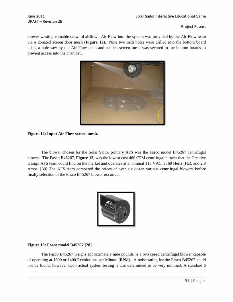
blower wasting valuable outward airflow. Air Flow into the system was provided by the Air Flow team
via a donated screen door mesh (Figure 12). Nine two inch holes were drilled into the bottom board
using a hole saw by the Air Flow team and a thick screen mesh was secured to the bottom boards to
prevent access into the chamber.
Figure 12: Input Air Flow screen mesh.
The blower chosen for the Solar Sailor primary AFS was the Fasco model B45267 centrifugal
blower. The Fasco B45267, Figure 13, was the lowest cost 460 CFM centrifugal blower that the Creative
Design AFS team could find on the market and operates at a nominal 115 VAC, at 60 Hertz (Hz), and 2.9
Amps. [30] The AFS team compared the prices of over six dozen various centrifugal blowers before
finally selection of the Fasco B45267 blower occurred.
Figure 13: Fasco model B45267 [28]
The Fasco B45267 weighs approximately nine pounds, is a two speed centrifugal blower capable
of operating at 1600 or 1400 Revolutions per Minute (RPM). A noise rating for the Fasco B45267 could
not be found; however upon actual system testing it was determined to be very minimal. A standard 6
June 2011 Solar Sailor Interactive Educational Game DRAFT – Revision 2B Project Report
32 | P a g e
feet, 16AWG power cable was used to connect the Fasco blower to a standard 6 outlet 115VAC power
strip, controlled by the micro controller via a relay.
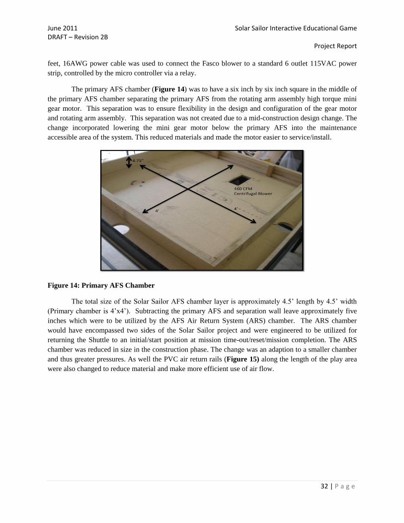
The primary AFS chamber (Figure 14) was to have a six inch by six inch square in the middle of
the primary AFS chamber separating the primary AFS from the rotating arm assembly high torque mini
gear motor. This separation was to ensure flexibility in the design and configuration of the gear motor
and rotating arm assembly. This separation was not created due to a mid-construction design change. The
change incorporated lowering the mini gear motor below the primary AFS into the maintenance
accessible area of the system. This reduced materials and made the motor easier to service/install.
Figure 14: Primary AFS Chamber
The total size of the Solar Sailor AFS chamber layer is approximately 4.5‟ length by 4.5‟ width
(Primary chamber is 4‟x4‟). Subtracting the primary AFS and separation wall leave approximately five
inches which were to be utilized by the AFS Air Return System (ARS) chamber. The ARS chamber
would have encompassed two sides of the Solar Sailor project and were engineered to be utilized for
returning the Shuttle to an initial/start position at mission time-out/reset/mission completion. The ARS
chamber was reduced in size in the construction phase. The change was an adaption to a smaller chamber
and thus greater pressures. As well the PVC air return rails (Figure 15) along the length of the play area
were also changed to reduce material and make more efficient use of air flow.

June 2011 Solar Sailor Interactive Educational Game DRAFT – Revision 2B Project Report
33 | P a g e
Figure 15: Air Return System – PVC Rails
It was initially determined by the Air Flow System team that two high CFM fans capable of
producing a minimum of 250 CFM would produce enough directed air flow to sufficiently accomplish the
task of repositioning the Shuttle. With the Solar Sailor ARS air chamber less than .672 Cubic Feet (CF)
in size (4‟x.42‟x.4‟=.672 CF) the air chamber shall receive more than enough in-chamber directed air
flow required to ensure appropriate repositioning of the Solar Sailor Shuttle. The Air Flow System team
initially reduced the size of the Air Return System into one combined smaller chamber (Figure 16) with
two 250 CFM fans to further increase airflow, however the output air flow was insufficient and it was
observed through several tests that the majority of airflow was exiting the system back through the High
CFM fans.

June 2011 Solar Sailor Interactive Educational Game DRAFT – Revision 2B Project Report
34 | P a g e
Figure 16: Air Return System – Modification of ARS Chamber
To fix the problem with the Air Return System two additional high CFM fans were purchased at
the beginning of week ten and installed by the Air Flow team directly above the primary air chambers.
These four high CFM fans were then tested and resulted in more than sufficient directional airflow
providing the force needed to return all test shuttles back to home (Figure 17).
Figure 17: Air Return System – Final Modification of the Air Return System

June 2011 Solar Sailor Interactive Educational Game DRAFT – Revision 2B Project Report
35 | P a g e
To accomplish the task of the ARS the AFS team reviewed over fifty compact DC fan designs,
however the vast majority of the designs analyzed were either too large and too costly, or were unable to
produce enough air flow necessary to meet the ARS objective. Luckily a small 120 mm x 120 mm x 38
mm (4.72 x 4.72 x 1.5 inch) 205 CFM fan was discovered. The ARS team chose to utilize two of the
ultra-high performance Mechatronics model MD1238X fans. The Mechatronics MD1238X, Figure 18, is
the most cost effective high CFM fan the ARS design team could find. The Mechatronics MD1238X
achieves 205 CFM of air by revolving at 4,500 RPM using 12 VDC at 2.5 Amps [29]. The Mechatronics
MD1238X weighs approximately 411g (411g is approximatelly.906lbs) and produces 62 dBA of noise.
For comparison a normal conversation is typically rated at 60-70 dB, and city traffic (inside car) typically
produces 85dB of noise. [30]. However this noise is still within safety limits and only occurs during the
return of the shuttle back to home at the end of each mission.
Figure 18: Mechatronix MD1238X Fan. [29]
As possible alternatives for the Mechatronics MD1238X fan the AFS team looked into using four
COMPAQ model PSD1212PMBX, 12VDC fans capable of 105 CFM each. The other big consideration
was whether to use two FFB model 1212EHE 12VDC fans rated at 190 CFM. However, the COMPAQ
fans were above budget constraints and would create too much system noise and the FFB fans were twice
the cost of the Mechatronics MD1238X. In order to control the Fasco B45267, 110VAC, 2.9A,
centrifugal blower and Mechatronics MD1238X, 12VDC, 2.5A, fan with the microcontroller the AFS
team reviewed several Single-Pole Single-Throw (SPST) relays.
A relay is essentially a large mechanical switch that can be toggled off or on by energizing a coil.
There are two parts to most relays, the contact and the coil. The contact part of the relay is the path in
which the primary devices power travels and is either open or closed [32]. In order to control the Fasco
B45267 and Mechatronics MD1238X the contact needed to be able to support at least 110VAC @ 2.9A
and 12VDC at 2.5A. For safety concerns the AFS design team researched relays capable of handling at
least a maximum load of 200VAC @5A and 28VDC @5A.

June 2011 Solar Sailor Interactive Educational Game DRAFT – Revision 2B Project Report
36 | P a g e
The coil is the second half of the relay and is basically a small electromagnet used to open/close
the switch. Several relays were looked at during this part of the research phase however most relays
looked at were costly and could not meet the requirements above. The microcontroller research team
specified that the microcontroller would be sending a 3VDC or 5VD signal at a range from 40 – 400 mA
to control the relay (using one or more pins).
In order to meet these requirements the AFS team found two inexpensive, quality, relays from
suppliers (Digikey and Sparkfun) recommended by the part procurement official. The two primary relays
identified by the AFS team were the Tyco T9A Series and the Panasonic DK Series shown by Figures 19
and 20 below.
Figure 19: Tyco T9A Series Relay [33]
Figure 20: Panasonic DK Series Relay [32]
June 2011 Solar Sailor Interactive Educational Game DRAFT – Revision 2B Project Report
37 | P a g e
The Panasonic DK1A-L2-3V-F relay (Digikey part number 255-2053-ND) has a contact rating of
10A and a maximum switching voltage of 250 VAC, 125 VDC [32]. The Panasonic DK1A-L2-3V-F
relay coil requires 3VDC at 66.7mA for switching the SPST relay on and off, however the relay is four
times the price of the Tyco T9A series (Sparkfun SKU: COM-00101) relay. The Tyco relay has a contact
rating of 30A and a maximum switching voltage of 240 VAC, 20A @ 28VDC [33].
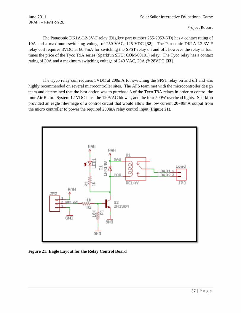
The Tyco relay coil requires 5VDC at 200mA for switching the SPST relay on and off and was
highly recommended on several microcontroller sites. The AFS team met with the microcontroller design
team and determined that the best option was to purchase 3 of the Tyco T9A relays in order to control the
four Air Return System 12 VDC fans, the 120VAC blower, and the four 500W overhead lights. Sparkfun
provided an eagle file/image of a control circuit that would allow the low current 20-40mA output from
the micro controller to power the required 200mA relay control input (Figure 21).
Figure 21: Eagle Layout for the Relay Control Board
June 2011 Solar Sailor Interactive Educational Game DRAFT – Revision 2B Project Report
38 | P a g e
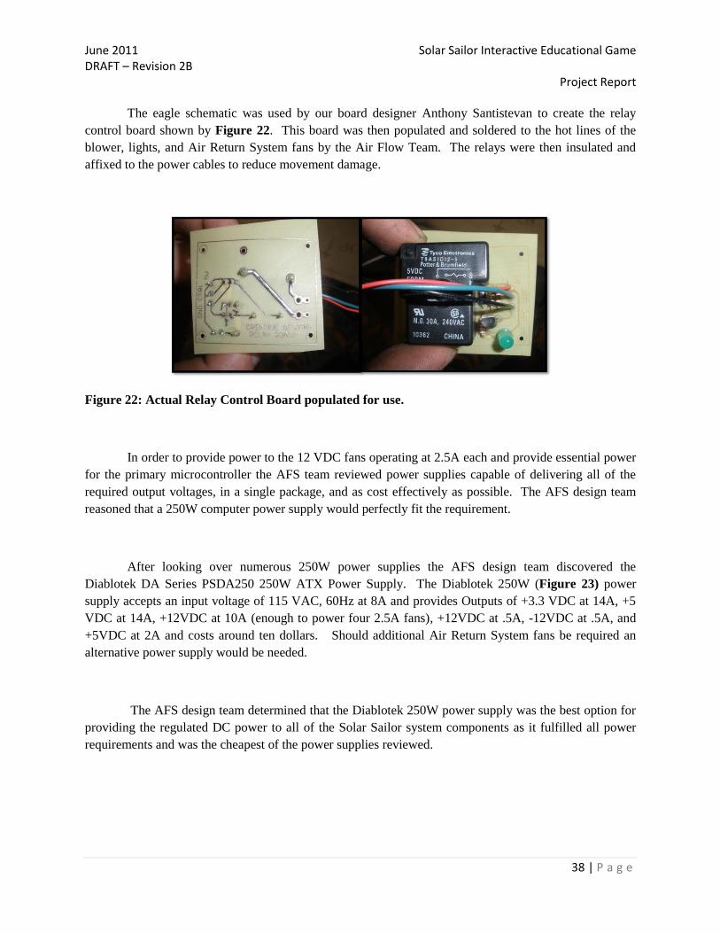
The eagle schematic was used by our board designer Anthony Santistevan to create the relay
control board shown by Figure 22. This board was then populated and soldered to the hot lines of the
blower, lights, and Air Return System fans by the Air Flow Team. The relays were then insulated and
affixed to the power cables to reduce movement damage.
Figure 22: Actual Relay Control Board populated for use.
In order to provide power to the 12 VDC fans operating at 2.5A each and provide essential power
for the primary microcontroller the AFS team reviewed power supplies capable of delivering all of the
required output voltages, in a single package, and as cost effectively as possible. The AFS design team
reasoned that a 250W computer power supply would perfectly fit the requirement.
After looking over numerous 250W power supplies the AFS design team discovered the
Diablotek DA Series PSDA250 250W ATX Power Supply. The Diablotek 250W (Figure 23) power
supply accepts an input voltage of 115 VAC, 60Hz at 8A and provides Outputs of +3.3 VDC at 14A, +5
VDC at 14A, +12VDC at 10A (enough to power four 2.5A fans), +12VDC at .5A, -12VDC at .5A, and
+5VDC at 2A and costs around ten dollars. Should additional Air Return System fans be required an
alternative power supply would be needed.
The AFS design team determined that the Diablotek 250W power supply was the best option for
providing the regulated DC power to all of the Solar Sailor system components as it fulfilled all power
requirements and was the cheapest of the power supplies reviewed.

June 2011 Solar Sailor Interactive Educational Game DRAFT – Revision 2B Project Report
39 | P a g e
Figure 23: Diabloteck 250W Power Supply [26].
Figure 24: Solar Sailor Air Flow Block Diagram.

June 2011 Solar Sailor Interactive Educational Game DRAFT – Revision 2B Project Report
40 | P a g e
Air Flow System parts required for assembly:
1 - Fasco B45267 Centrifugal Blower (460 CFM)
4 - Mechatronics MD1238 Fans (205 CFM each)
3 – PWR Relays SPST-NO 30A
1 - Diablotek DA Series 250W ATX Power Supply
1 – 18 AWG Power Cable
1 – 6 Outlet 110VAC, 15A Surge Protector
3 - 4.5'L x 4.5'W x.75"H Hardwood boards
4 - 4.5'W x 10"L x .75"H Hardwood boards
4 - 4.5'W x 5"L x .75"H Hardwood boards
2 - 4.5'W x 5"L x .75"H Hardwood boards
4 - 1'L x 2"W x .75"H Hardwood boards
2 – 18 fl. oz. bottles of Gorilla Glue (Wood)
4 – 3M containers of Silicon Sealant
Safety Considerations
All the components of the Air Flow Systems are not accessible to the users, unless the plaxiglass
is removed from the Solar Sailor game or the relays, power and centrifugal blower is accessed from the
access panel. For maintanance considerations all the parts required to replace any of the components are
listed in the Appendix under the Part List.
CAUTION: The Air Return System 12VDC fan blades and Centrifugal blower have sharp blades
and cause cutting injuries. Remove and replace units if malfunctioning. Do not run fans/blower
while Plexiglas is removed or access panel is open.
WARNING: Do not remove any components of the air system (fans/blower) and/or power
system (AC outlet, relays, tamper switch, power supply, surge protector, grounding wire) unless
the Solar Sailor Game is powered off (to include primary power, surge protector, and power
supply) and disconnected from the electrical outlet. Failure to disconnect the Solar Sailor game
could result in death by Electrical Shock.

June 2011 Solar Sailor Interactive Educational Game DRAFT – Revision 2B Project Report
41 | P a g e
Informational Display Board, Backdrop and User Interface graphics
Lead Engineers and Designers: Loren Schwappach and Barry Farley (Chimaera) (Primary) and
Taylor DeIaco (Alternate)
The Solar Sailor informational display (Figure 25) was designed by Loren Schwappach
using a royalty free image of the sun and the eight planets created by NASA. NASA authorized
the modification and use of the image for educational or informational purposes, including photo
collections, textbooks, public exhibits and Internet Web pages. The NASA image was resized
and altered using GIMP (A freeware graphics editor) to make the image appear more surreal and
the names, graphics and planetary/physics information was added as separate layers with 75%
transparency. Facts about each of the eight planets (to include: diameter, mass (relative to earth),
avg. density, distance from sun, surface gravity, orbital time, number of moons, and surface
temperature were compiled using several sources with NASA being the primary), Newton and
Keplers three laws and information about achieving orbit were also added to the illustration to
increase the audiences understanding of gravity, inertia, forces, and frictionless motion in space.
Figure 25: Solar Sailor Informational Display

June 2011 Solar Sailor Interactive Educational Game DRAFT – Revision 2B Project Report
42 | P a g e
The Solar Sailor backdrop (Figure 26) was created by Barry Farley (CTU Chimaera).
The design was created to illustrate the creativity and wonder of space travel while playing the
Solar Sailor game.
Figure 26: Solar Sailor Backdrop
The Solar Sailor User Interface (Figure 27) was conceived initially by Taylor DeIaco.
This design was then modified / resized by Loren Schwappach with the colors, instructions (in
English and Spanish) and planetary scheme of the backdrop poster to provide a unified vision of
the game.
Figure 27: Solar Sailor User Interface

June 2011 Solar Sailor Interactive Educational Game DRAFT – Revision 2B Project Report
43 | P a g e
Spaceship Component
Lead Engineers and Designers: Anthony Santistevan and Joe Rodriguez
Contributing Engineer: Taylor DeIaco
The Solar Flyer (Shuttle) is the physical representation of the interactive element of the system
design. The item will be created from scratch using plastic resin molding techniques. Creating the play
piece from scratch will allow for having direct input to the amount of mass introduced to the air table.
This will make it easier to accurately simulate zero friction environment provided by the air table.
The plastic resin molding process also produces a robust product that will be able to withstand the
stresses of accidental collisions. The molding process will first require creating a clay positive of the
spaceship. This spaceship will then be hollow molded to provide area inside the fuselage for installing
the needed components.
Weight was the primary consideration when casting the base and fuselage of the shuttle.
Research initially pointed towards air hockey pucks having a mass between 18 and 48 grams. Testing on
the completed air table showed that movement was likely when the shuttle was under a mass of 44 grams.
In order to move a higher mass shuttle, more airflow by way of an additional blower will be required.
Finished product mass is 42g with all components added.
The base will be 3.5" in diameter and 1" tall. The base will be left open air. This will allow for
the storage of the electrical components and assist with keeping under the mass limit. The fan rotors will
be 1.5" diameter for the fore and aft directional motors, and 1.5" diameter for the forward and reverse
thrust motor in the rear. The rotors were sourced from a local hobby shop as inconsistencies with the
molding process were interfering with the aerodynamics needed for movement.
Figure 28: Graphic Representation, top view of the spaceship component, planned and actual [12]
The spaceship will be controlled by an amplitude modulated radio frequency (RF) serial data
stream from the joy stick controller by way of the main microcontroller. This signal will be input to the

June 2011 Solar Sailor Interactive Educational Game DRAFT – Revision 2B Project Report
44 | P a g e
spaceship at the 433MHz Receiver. This receiver was chosen due to the low availability of small form
low power RF receivers. The serial data stream is then decoded by the ATtiny24 microprocessor.
Individual control signals are then sent to the Inverting Buffer IC from the ATtiny24, and subsequently
used as biasing for the transistor arrays that will directly drive the motors. A crystal oscillator is utilized
to stabilize the clock signals of the ATtiny24 microprocessor.
A circuit diagram is provided below in Figure 29. A larger version of this figure can also be found in the
Appendix for easier viewing.
Figure 29: Circuit Diagram, Spaceship Component [14][15] (See Appendix)
Power is provided to the mobile spaceship by way of solar cells. The fan motors are connected to
an unregulated 3.3V solar circuit. The max provided current of this circuit is estimated to be 80mA.
Testing under the current lighting scheme yields the available current of 67mA. The max draw of the
motor circuit at any given time is 50mA [15]. The control signal flow is separated to an unregulated 6.5V
solar power supply circuit. This is done to ensure that the higher current draw of the motors will not
interfere with receiving commands from the MCU. The max current provided by this circuit is estimated
at 33mA, and the max current draw is estimated at 12mA [18]. All components were populated onto a
custom printed circuit board (PCB) shown in Figure 30. The process for creating the PCB is listed in the
Appendix.

June 2011 Solar Sailor Interactive Educational Game DRAFT – Revision 2B Project Report
45 | P a g e
Figure 30: Graphic Representation side view, planned and actual, and PCB[13].
The spaceship will be controlled by three small fans. Two fans will be place fore and aft of the
spaceship perpendicular to the fuselage as shown in Figure 30. The two motors will be wired into the
circuit inversely; if one motor is running forward, the second will be running in reverse. When the fore
motor is running forward and the aft is running reverse, the spaceship will achieve a clockwise rotation.
If the signal is reversed, the fore motor will be running in reverse and the aft motor will run forward, and
the ship will achieve a counterclockwise rotation. These actions allow the spaceship to point in the
desired direction. The third fan in the rear is the thrust fan. The rear fan enables forward and reverse
movement in whichever direction it is respectively pointed.
User Begins Game
By Pressing Start
Button
System Idle
User Input
Direction
Fore Fan Forward;
Aft Fan ReverseCounter-Clockwise
Rear Fan Forward
Fore Fan Reverse;
Aft Fan ForwardClockwise
Rear Fan Reverse
Planetary
Capture?User input?
Reverse
Success
Forward
Power
Available?
Yes
Yes
Wait for Solar
Cells to Charge
System
No
Yes
No
No
Figure 31: Behavioral Flowchart of the Spaceship (See Appendix)

June 2011 Solar Sailor Interactive Educational Game DRAFT – Revision 2B Project Report
46 | P a g e
Control signals received from the MCU will follow this table:
Directional Motor Array
Input1 Enable1 Motor
X H Standby
H L Clockwise
L L Counter-Clockwise
Thrust Motor Array
Input 2 Enable 2 Motor
X H Standby
H L Forward
L L Reverse
Table 2: Truth Table, Motor Control Circuit [14]
The spaceship will also have a permanent magnet that will activate the proximity sensor located
at home base and the Planet Driver. The magnet will be mounted on the starboard side of the spaceship in
order to simulate a spaceship in orbit. The operator will need to align the magnet with the sensor and
capture device to ensure a successful orbit.
Spaceship Parts required for assembly:
3 – Small Pager Motor.
2 - 37 x 33mm Monocrystalline Solar Cell
1 - Receiver AM Mini Hybrid 433MHZ
4 - Transistor Array NPN and PNP DUAL 30V
2 - Capacitor 1000uF 25V
2 - Capacitor .1uF 25V
1 - 74HC240 Enable line Invertor
1 - ATTINY24-20PU-ND 14 Pin Microcontroller
8 - 1KΩ Resistor
1 – Crystal Oscillator
1 – completed circuit board
1 – neodymium magnet
1 liter - Plastic Resin Molding Materials
500g - Molding Clay
June 2011 Solar Sailor Interactive Educational Game DRAFT – Revision 2B Project Report
47 | P a g e
Planet Driver Component
Lead Engineers and Designers: Noemi Wikstrom and Jeremy Struebing
Alternate Engineers and Contributors: William McNally, Taylor DeIaco, Anthony Santistevan
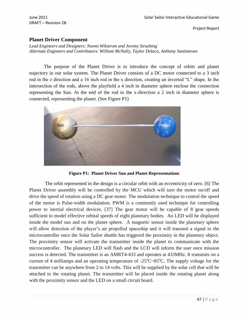
The purpose of the Planet Driver is to introduce the concept of orbits and planet
trajectory in our solar system. The Planet Driver consists of a DC motor connected to a 3 inch
rod in the z direction and a 16 inch rod in the x direction, creating an inverted “L” shape. In the
intersection of the rods, above the playfield a 4 inch in diameter sphere enclose the connection
representing the Sun. At the end of the rod in the x-direction a 2 inch in diameter sphere is
connected, representing the planet. (See Figure P1)
Figure P1: Planet Driver Sun and Planet Representations
The orbit represented in the design is a circular orbit with an eccentricity of zero. [6] The
Planet Driver assembly will be controlled by the MCU which will turn the motor on/off and
drive the speed of rotation using a DC gear motor. The modulation technique to control the speed
of the motor is Pulse-width modulation. PWM is a commonly used technique for controlling
power to inertial electrical devices. [37] The gear motor will be capable of 8 gear speeds
sufficient to model effective orbital speeds of eight planetary bodies. An LED will be displayed
inside the model sun and on the planet sphere. A magnetic sensor inside the planetary sphere
will allow detection of the player‟s air propelled spaceship and it will transmit a signal to the
microcontroller once the Solar Sailor shuttle has triggered the proximity in the planetary object.
The proximity sensor will activate the transmitter inside the planet to communicate with the
microcontroller. The planetary LED will flash and the LCD will inform the user once mission
success is detected. The transmitter is an AMRT4-433 and operates at 433MHz. It transmits on a
current of 4 milliamps and an operating temperature of -25oC~85
oC. The supply voltage for the
transmitter can be anywhere from 2 to 14 volts. This will be supplied by the solar cell that will be
attached to the rotating planet. The transmitter will be placed inside the rotating planet along
with the proximity sensor and the LED on a small circuit board.
Sun Planet
June 2011 Solar Sailor Interactive Educational Game DRAFT – Revision 2B Project Report
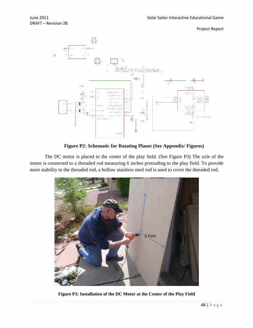
48 | P a g e
Figure P2: Schematic for Rotating Planet (See Appendix/ Figures)
The DC motor is placed in the center of the play field. (See Figure P3) The axle of the
motor is connected to a threaded rod measuring 6 inches protruding to the play field. To provide
more stability to the threaded rod, a hollow stainless steel rod is used to cover the threaded rod.
Figure P3: Installation of the DC Motor at the Center of the Play Field
2 Feet

June 2011 Solar Sailor Interactive Educational Game DRAFT – Revision 2B Project Report
49 | P a g e
The “sun” was originally design to be represented by 4” diameter hemisphere (Sun).
However; one of the main concerns was to provide the user with more play field area to
maneuver the spaceship. It was decided to use a Sphere instead located above the playfield about
4 inches above the surface. A 16 inch shaft is connected to the main rod in the y-direction. A 2
inch diameter plastic sphere is attached to the secondary shaft representing the planet.
The motor move the shaft and planet around the sun with an orbit circumference of 2πr =
9.42 feet. Using the circumference of 9.42 feet we can calculate the required motor velocities
scaled to the Planet Driver. Assuming that one revolution equates to 10 seconds and 60 seconds
equate to 1 minute. At maximum speed the motor rotates at 6 rpm.
To represent the planet‟s rotations around the sun, the speed of the motor will be
controlled by the comparison of the planet‟s orbital (Earth days) rotations around the sun. For
example, Mercury has the smallest orbit, it take approximately 88 days to complete a rotation
[6]. Equating Mercury‟s orbital rotation at 6 rpm, we can scale the rest of the planet‟s orbital
speeds. The table below lists the calculated planet‟s orbital speeds scaled for the planet driver.
Planet rpm
Mercury 6
Venus 5
Earth 4
Mars 3
Jupiter 0.5
Saturn 0.25
Uranus 0.125
Neptune 0.025
Table P1: Planet Driver revolutions per minute for each planet
The sphere (planet) connected to the rotating shaft will contain a flashing LED. The LED will
light up when the spaceship reach the planet. To be able to detect the spaceship the planet will also serve
as a sensor. Inside the sphere a 3.6 x 5.0 x 1.0 mm [7] proximity sensor will detect the changes in the
magnetic field when the spaceship has reached the planet.

June 2011 Solar Sailor Interactive Educational Game DRAFT – Revision 2B Project Report
50 | P a g e
Figure P4: Proximity Sensor with leads in the ports.
The 2-Axis Magnetic sensor uses the strength and the direction of the magnetic field to measure
in a range of +/- 2 Gauss. The sensor will transmit the signal to microcontroller and the component will
stop and the game reset. In Figure 4, notice that the magnetic sensor has a very small (~3mm x 4mm)
surface mount IC package making the pins extremely small and difficult to prototype. For that reason, the
magnetic sensor is mounted to a PCB for easier connection to rest of the Planet Driver circuit.
The planet circuit contains an A tiny microcontroller brain. This processor takes the magnetic
sensor voltage as in input, analyses this voltage level, and outputs a pulse width modulated signal
according to whether or not the magnetic sensor‟s voltage level is higher than a threshold level. The
outputted pulse width modulated signal is routed into a RF transmitter to be broadcast to the CPU
receiver.
To provide power to the sensor inside the planet and the flashing LED, a 37 x 33mm Mono-
Crystalline Solar Cell will be also attached to the planet circuit board. The solar cell will provide 6.1 volts
at 23mA. The reason Solar Cells are used instead of routing power from the main power supply, is that
the planet is rotating, and any wires being routed through the planet shaft will twist together until they
break.
Figure P6: Soldering of the 24 gauge wire to the DC Motor for the Planet Driver

June 2011 Solar Sailor Interactive Educational Game DRAFT – Revision 2B Project Report
51 | P a g e
The Planet Driver component will use a DC Motor: High Torque Mini DC Gear Motor 3-12V, 5-
25 rpm. The nominal operating voltage is 6 volts with an operating voltage range of 3 – 12 volts and an
operating life 8000 hours.[8] The diameter of the spindle is 7 mm and the motor is 40 mm long and 48
mm in diameter. The power will be provided by the power supply unit of the Solar Sailor Table.
The motor speed will be varied using pulse-width modulation (PWM). The average value of
voltage (and current) fed to the load is controlled by providing power only a certain percent of time,
effectively slowing the motors speed. [9] The PWM will be controlled by a signal from the
microcontroller.
Figure P7: DC Motor: High Torque Mini DC Gear Motor. [8]
The following flowchart represents the behavior of the Planet Driver component.
Figure P8: Solar Sailor Planet Driver Behavior flowchart.
Planet Driver Parts required for assembly:

June 2011 Solar Sailor Interactive Educational Game DRAFT – Revision 2B Project Report
52 | P a g e
1 - 4” diameter Plastic Sphere
1 - 2” diameter Plastic Sphere
1 - Proximity Sensor. HMC6042- 2-Axis Magnetic Sensor
1 - 37 x 33mm Mono-crystalline Solar Cell
1 – TWS-434 Transmitter
1 – 16 inch metal rod
1 – 12 inch metal rod
1 – Threaded Rod
1 – LED
In the process of the planet driver design, some parts were eliminated or replaced. The original
idea was to run wires through a PVC pipe to supply power for the components inside the planet. The
problem encountered was the realization that the wires will twist, and damage the signal line. The solution
is to use solar cells embeded in the planet to provide power for the electrical components, remotly, from
inside the plant. The other issue with the design was the use of PVC pipe, which is not aesthetically
pleasing. The solution was to use, thin metallic rods, which are very resistant and lighter than the PVC.
An added benefit of the lighter metallic rods are in the load for the motor. The spheres use in the design,
were chosen due to durability and cost, the spheres are made of plastic as opposed to metal or glass.
Although there were several alternatives for the gear motor, the team decided to use the High Torque
Mini DC Gear motor [8] depicted in Figure P7 due to its comparable price and efficiency. The threaded
rods are covered by stainless steal hollow rods to provide stability to the motor axle and prevent bending
due to the load.
Recommendation from Tailor DeIaco
The result of the planet driver was that it worked as expected. There seems to be a minot stability
issue at the sun. The time constraint did not allow for final testing of the motor or installation of the
electronics into the rotating planet. There are a couple of things that can be improved in the planet driver
assembly. First add a small rod inside the sun at the 90o turn for added stability. Second, replace the
connector with an elbow. The last thing that could be improved on is the shaft leading out to the rotating
planet. This could be a solid piece of material.
Safety Considerations
All the component of the Planet Driver are not accessible to the users, unless the plaxiglass is removed
from the Solar Sailor game or the motor is access from the bottom section of the Play field. For
maintanance considerations all the parts required to replace any of the components are listed in the
Appendix under the Part List.

June 2011 Solar Sailor Interactive Educational Game DRAFT – Revision 2B Project Report
53 | P a g e
The paint used to decorate the “Sun” and the “Planet” do not contain lead, as required by the United
States Environmental Protection Agency.
WARNING: Do not remove any components of the Planet Driver unless the Solar
Sailor Game is disconnected from the electrical outlet. Failure to disconnect the
Solar Sailor game could result in Electrical Shock.
Power Distribution
Lead Engineer: Loren Schwappach, Alternate Engineer: William McNally
The purpose of the Power Distribution System is to supply power to all of the
components of the Solar Sailor. Primary power is fed into the system from an external 120VAC
20A outlet via a 12 AWG cable to an internal 20A outlet controlled by a primary 30A capable
on/off switch and a 20A capable tamper switch (via the hot/black wire). This power then feeds a
15A Surge Protector Power Strip (with a 15A circuit breaker). The circuit breaker feeds all of
the units of the Solar Sailor to include the 120VAC, 2A (240W) power for the Air Flow System
blower controlled via relay, the 250W Power Supply feeding the microcontroller and Air Return
System fan relay powering four 12V, 2.5A fans (10A, 120W), and the Solar Sailor 2000W solar
cell lighting system powering four 500W halogen lights via a 15A 120VAC outlet and controlled
by the microcontroller via relay. The Solar Sailor was designed so that the lighting system and
fans would not operate at the same time and if so trip the 15A surge protector. This was more of
a game design feature (to add effect when the player completes his/her mission) than a system
and user safety feature but was essential after redesigning the Air Flow Return System to utilize
four fans vs. two and tripling the power of the lighting system to utilize 500W vs. 150W halogen
bulbs. The frame itself was further grounded as an additional safety measure.
Figure 32: Wiring of the Power Distribution System
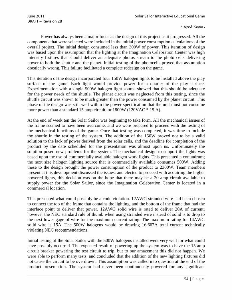
June 2011 Solar Sailor Interactive Educational Game DRAFT – Revision 2B Project Report
54 | P a g e
Power has always been a major focus as the design of this project as it progressed. All the
components that were selected were included in the initial power consumption calculations of the
overall project. The initial design consumed less than 300W of power. This iteration of design
was based upon the assumption that the lighting at the Imagination Celebration Center was high
intensity fixtures that should deliver an adequate photos stream to the photo cells delivering
power to both the shuttle and the planet. Initial testing of the photocells proved that assumption
drastically wrong. This failure facilitated a complete redesign on the game.
This iteration of the design incorporated four 150W halogen lights to be installed above the play
surface of the game. Each light would provide power for a quarter of the play surface.
Experimentation with a single 500W halogen light source showed that this should be adequate
for the power needs of the shuttle. The planet circuit was neglected from this testing, since the
shuttle circuit was shown to be much greater than the power consumed by the planet circuit. This
phase of the design was still well within the power specification that the unit must not consume
more power than a standard 15 amp circuit, or 1800W (120VAC * 15 A).
At the end of week ten the Solar Sailor was beginning to take form. All the mechanical issues of
the frame seemed to have been overcome, and we were prepared to proceed with the testing of
the mechanical functions of the game. Once that testing was completed, it was time to include
the shuttle in the testing of the system. The addition of the 150W proved not to be a valid
solution to the lack of power derived from the solar cells, and the deadline for completion of the
product by the date scheduled for the presentation was almost upon us. Unfortunately the
solution posed new problems for the system. The mechanical design to support the lights was
based upon the use of commercially available halogen work lights. This presented a conundrum;
the next size halogen lighting source that is commercially available consumes 500W. Adding
these to the design brought the power consumption of the product to 2300W. Team members
present at this development discussed the issues, and elected to proceed with acquiring the higher
powered lights, this decision was on the hope that there may be a 20 amp circuit available to
supply power for the Solar Sailor, since the Imagination Celebration Center is located in a
commercial location.
This presented what could possibly be a code violation. 12AWG stranded wire had been chosen
to connect the top of the frame that contains the lighting, and the bottom of the frame that had the
interface point to deliver that power. 12AWG solid wire is rated to deliver 20A of current;
however the NEC standard rule of thumb when using stranded wire instead of solid is to drop to
the next lower gage of wire for the maximum current rating. The maximum rating for 14AWG
solid wire is 15A. The 500W halogens would be drawing 16.667A total current technically
violating NEC recommendations.
Initial testing of the Solar Sailor with the 500W halogens installed went very well for what could
have possibly occurred. The expected result of powering up the system was to have the 15 amp
circuit breaker powering the test circuit to trip, but to our amazement this did not happen. We
were able to perform many tests, and concluded that the addition of the new lighting fixtures did
not cause the circuit to be overdrawn. This assumption was called into question at the end of the
product presentation. The system had never been continuously powered for any significant

June 2011 Solar Sailor Interactive Educational Game DRAFT – Revision 2B Project Report
55 | P a g e
length of time and after the presentation had concluded and the product was being viewed by the
audience, the overload protection on the power strip that is used for power distribution for the
120VAC devices tripped. After resetting the overload protection, it tripped again after some
length of time. This is an indication that the power distribution design has failed to deliver
adequate power for the unit.
To overcome this failure will require certain experiments to be run to make the system
functional. First the actual draw of the halogen lights needs to be measured. Our testing showed
that the lights are not actually consuming 500W of power each, since the four lamps in parallel
did not trip a standard 15 amp circuit breaker. However the fact that the overload protection of
the power strip trips after some length of time indicates that the system is at the borderline of
exceeding the power specifications. Once the actual current is measured to the lights, it may be
possible to redistribute the power through multiple surge protected devices, so that individual
devices can derive power from different legs of the circuit. This approach would require two
supply circuits from the base to the top of the frame so that only two lights derive power from
the same power distribution point.
Power System Parts required for assembly:
1 – 30A, Primary Power On/Off Button
1 – 20A, 120VAC Outlet
1 – 20A, Tamper switch
1 – 6 Outlet 110VAC, 15A Surge Protector
2 – 12ft, 12 AWG Power Cables
1 - Diablotek DA Series 250W ATX Power Supply
3 – PWR Relays SPST-NO 30A
Safety Considerations
All the components of the Power System are not accessible to the users, unless the plaxiglass is
removed from the Solar Sailor game or the relays, wires, and power control devices are accessed via the
access panel. For maintanance considerations all the parts required to replace any of the components are
listed in the Appendix under the Part List.
WARNING: Do not remove any components of the power system (AC outlet, relays,
tamper switch, power supply, surge protector, grounding wire, and wiring) unless
the Solar Sailor Game is powered off (to include primary power, surge protector,
and power supply) and disconnected from the electrical outlet. Failure to
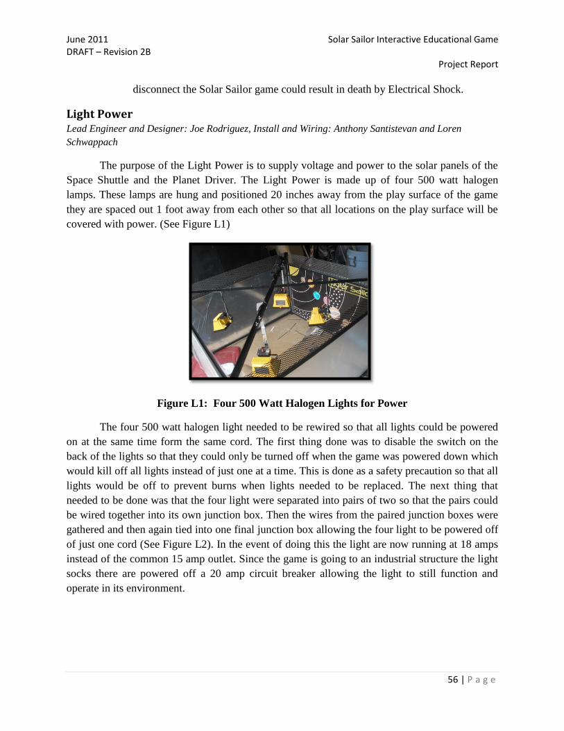
June 2011 Solar Sailor Interactive Educational Game DRAFT – Revision 2B Project Report
56 | P a g e
disconnect the Solar Sailor game could result in death by Electrical Shock.
Light Power Lead Engineer and Designer: Joe Rodriguez, Install and Wiring: Anthony Santistevan and Loren
Schwappach
The purpose of the Light Power is to supply voltage and power to the solar panels of the
Space Shuttle and the Planet Driver. The Light Power is made up of four 500 watt halogen
lamps. These lamps are hung and positioned 20 inches away from the play surface of the game
they are spaced out 1 foot away from each other so that all locations on the play surface will be
covered with power. (See Figure L1)
Figure L1: Four 500 Watt Halogen Lights for Power
The four 500 watt halogen light needed to be rewired so that all lights could be powered
on at the same time form the same cord. The first thing done was to disable the switch on the
back of the lights so that they could only be turned off when the game was powered down which
would kill off all lights instead of just one at a time. This is done as a safety precaution so that all
lights would be off to prevent burns when lights needed to be replaced. The next thing that
needed to be done was that the four light were separated into pairs of two so that the pairs could
be wired together into its own junction box. Then the wires from the paired junction boxes were
gathered and then again tied into one final junction box allowing the four light to be powered off
of just one cord (See Figure L2). In the event of doing this the light are now running at 18 amps
instead of the common 15 amp outlet. Since the game is going to an industrial structure the light
socks there are powered off a 20 amp circuit breaker allowing the light to still function and
operate in its environment.

June 2011 Solar Sailor Interactive Educational Game DRAFT – Revision 2B Project Report
57 | P a g e
Figure L2: Rewired 500 Watt Halogen Lamps
The four 500 watt halogen lights get very hot so as a safety measure the lights only power up
when the game is about to start and immediately powers down once the game is not in use. This is done
because while the game is running the air form the play surface is being release up and over the light
and out the top was vented. This is controlled by the games internal CPU and programming. The lights
are also aimed away from the glass so that children or adults will not go blind while playing the game.
When first designed we used four 150 watt Halogen Lamps thinking that this would be enough
light to power the solar cells from 20 inches above the play surface. After running some test and not
being able to get the solar cells to even charge off of these Halogens we decided to go to the four 500
which worked and accomplished the goal of powering the cells. The only problem with going to the 500
watt halogens is that they get much hotter faster than the others.
Safety Considerations
All the components of the Light System are not accessible to the users, unless the plaxiglass is removed
from the Solar Sailor game. For maintanance considerations all the parts required to replace any of the
components are listed in the Appendix under the Part List.
CAUTION: The halogen light bulbs and ventilation area may become hot during increased game
play. Do not touch or expose flammable objects to the upper game chamber.
WARNING: Do not remove any components of the air system (fans/blower) and/or power
system (AC outlet, relays, tamper switch, power supply, surge protector, grounding wire) unless
the Solar Sailor Game is powered off (to include primary power, surge protector, and power
supply) and disconnected from the electrical outlet. Failure to disconnect the Solar Sailor game
could result in death by Electrical Shock.
June 2011 Solar Sailor Interactive Educational Game DRAFT – Revision 2B Project Report
58 | P a g e
Control Logic Lead Engineer and Designer: William McNally
The control logic flow for the game is initialized at power up. By default the ADuC7026
embedded controller will start executing code stored in non-volatile memory at address 0x8000.
Once the device completes its initialization a two second delay loop will be entered allowing the
RF devices to synchronize. Once the loop completes, the HomeMagSensor will be polled to
ensure that the shuttle is in its default location. If this test fails, ReturnMode module will
execute, and the game return system will return the shuttle to its home.
The system will then enter IdleMode. In IdleMode the system will play the 15 minute
loop of space sounds that are stored on an SD card in the SOMO-14D embedded audio-sound
module. If the system does not receive a user generated interrupt, i.e. a player pressing the start
button, the system will enter a 15 minute SleepMode. Once the sleep period has elapsed the
system will again enter the IdleMode state, to gain attention of potential players.
PreGameMode is entered upon a user generated interrupt, i.e. pressing the start button. A
welcome message will be displayed upon the LCD display and the English/Spanish Audio tracks
will explain the planning and objectives of the missions. The next audio file to play will be the
Mission Select track. The system will then wait for 30 seconds waiting for the user to select the
planet that they will to try to land on. If no mission is selected, the then repeats the Mission
Objective, Mission Planning and Mission Select audio tracks. If no user input is generated after a
second loop through these audio tracks, the game will return to IdleMode.
Once the user presses one of the mission select buttons, the PlanetStatistics parameters
will be loaded into the proper registers to initialize the rotational speed of the planet. The user
will then be prompted to press the start button to continue with the selected mission. If the user
presses a different mission button, new PlanetStatistics parameters will be loaded and the speed
will be change appropriately. The planets speed will range from 0.125 RPMs to 6 RPMs to
comply with the calculated orbital mechanics.
The user will accept a mission by pressing the start button, and the mission countdown
will commence. At this point, the overhead lights will turn on, the main blower will turn on and
the audio countdown will commence. The Blast Off track will indicate a transition from
PreGameMode to GameMode, and the joy stick will be enabled for the user to control the
shuttle.
Upon entering GameMode, the system will play the Mission Control track to assist the
user in controlling the shuttle. A JoyStickUp interrupt will be generated every time that the
system detects the joy stick being pressed forward, causing forward thrust to be applied. A
JoyStickDown interrupt will be generated every time the joy stick is pulled back by the user,
causing reverse thrust to be applied to the shuttle. A JoyStickLeft interrupt will be generated
every time the joy stick is moved to the left, this will apply a counterclockwise rotation to the
shuttle. A JoySticRight interrupt will be generated every time the joy stick is moved to the right,
this will generate a clockwise rotation to the shuttle. No diagonal movements of the joy stick will

June 2011 Solar Sailor Interactive Educational Game DRAFT – Revision 2B Project Report
59 | P a g e
be recognized, so the shuttle cannot simultaneously receive rotate and a forward/reverse
commands.
The system will stay in GameMode as long as the player continues to generate interrupts
controlling the shuttle, has not exhausted the mission fuel supply or the player successfully
concludes the mission. If no user interrupt is received for 60 seconds, the game will enter
SleepMode. If during the course of play, the user consumes the allotted fuel supply, the main
blower will turn off, and an audio track will inform the user that the mission has failed. The fuel
level for each mission is one of the planet parameters loaded into a register in the processor. This
register will be decremented for every 250mS that the joy stick is enabled. 15 seconds after the
main blower shuts down, the system will enter ReturnMode and return the shuttle to its home.
The final exit from GameMode is when the user completes the mission successfully. A
successful mission is defined by the user “orbiting” the planet for a period of five seconds. This
period would be measured by the PlanetMagSensor staying true for a period of three seconds.
Upon successfully completing the mission the main blower will shut off, the planet will stop
rotation, and an audio track will informed the user that they have successfully completed the
mission. The system will enter ReturnMode after 15 seconds has elapsed.
The only exception to this normal control flow is if at any time an interrupt is detected
that the user has pressed the reset button. This exception will have different affects depending
upon the mode that the game is in when the interrupt is received. If the game is in IdleMode, the
reset will have no effect upon the system. If the game is in PreGameMode the system will return
to IdleMode. If the system is in GameMode, the overhead lights will be extinguished and the
system will enter ReturnMode.
Microcontroller Unit Lead Engineer and Designer: William McNally
At the start of week one of this quarter an unwise decision was made in how the project
was to proceed. The decision was based upon the assumption that incorporating the Atmel
ATmega16 controller would simplify communications between the system and the shuttle. The
shuttle includes an ATtiny14 controller has part circuitry, and the two controllers are members of
the same family. This assumption continued to influence our design decisions until an oversight
was discovered. This oversight was the ability to control the SOMO-14D. Three GPIO lines are
required to control the SOMO and all GPIO functionality of the ATmega16 had been consumed.
This was a major obstacle to the successful completion of the project.
The ATmega16 was replaced with the Analog Devices ADuC7026 Precision Analog
Microcontroller. Because of this change, all development work on the software to control the
system was render naught, and would have to be developed from scratch, since the command
sets of the two microcontrollers are not compatible. This even coincided with the major build
phase of the frame of the project, and the software development of the system took a backseat to
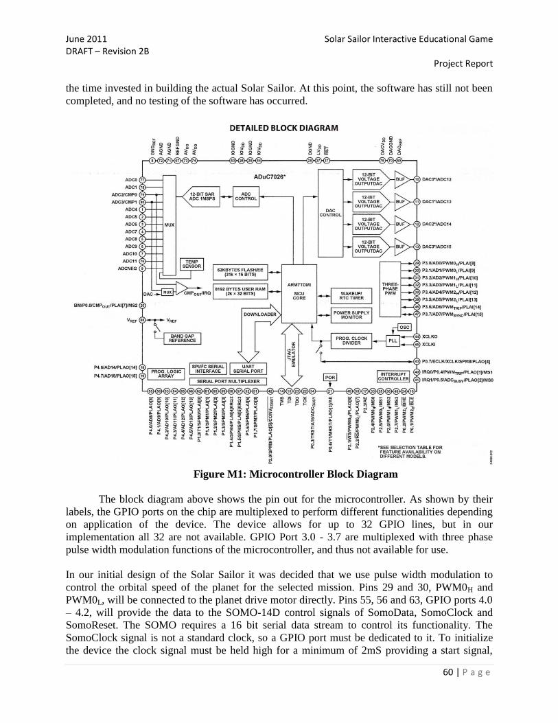
June 2011 Solar Sailor Interactive Educational Game DRAFT – Revision 2B Project Report
60 | P a g e
the time invested in building the actual Solar Sailor. At this point, the software has still not been
completed, and no testing of the software has occurred.
Figure M1: Microcontroller Block Diagram
The block diagram above shows the pin out for the microcontroller. As shown by their
labels, the GPIO ports on the chip are multiplexed to perform different functionalities depending
on application of the device. The device allows for up to 32 GPIO lines, but in our
implementation all 32 are not available. GPIO Port 3.0 - 3.7 are multiplexed with three phase
pulse width modulation functions of the microcontroller, and thus not available for use.
In our initial design of the Solar Sailor it was decided that we use pulse width modulation to
control the orbital speed of the planet for the selected mission. Pins 29 and 30, PWM0H and
PWM0L, will be connected to the planet drive motor directly. Pins 55, 56 and 63, GPIO ports 4.0
– 4.2, will provide the data to the SOMO-14D control signals of SomoData, SomoClock and
SomoReset. The SOMO requires a 16 bit serial data stream to control its functionality. The
SomoClock signal is not a standard clock, so a GPIO port must be dedicated to it. To initialize
the device the clock signal must be held high for a minimum of 2mS providing a start signal,

June 2011 Solar Sailor Interactive Educational Game DRAFT – Revision 2B Project Report
61 | P a g e
then it provides the clocked for the serial data stream. To terminate the data stream the
SomoClock signal must be held high for a minimum of 2mS.
The user interface encoder circuit will interface with the kernel using pins 61, 60, 59 and 58,
GPIO ports P1.1 – P1.4 respectively. The table below summarizes the user interface data.
Address Function
0000 JoyStickForward
0001 JoyStickBack
0010 JoyStickLeft
0011 JoyStickRight
0100 START
0101 RESET
0110 N/A
0111 N/A
1000 Mercury
1001 Venus
1010 Earth
1011 Jupiter
1100 Saturn
1101 Neptune
1111 Uranus
Table M1: User Interface Data
The table below contains the track addresses within the SD card for the SOMO-14D
Track Address
Solar Sailor Sound Track 0000.ad4
Press Start 0001.ad4
Mission Select 0002.ad4
Mission Planning 0003.ad4
Mission Objectives 0004.ad4
Count Down 0005.ad4
Blast Off 0006.ad4
Mission Control 0007.ad4
Mission Complete 0008.ad4
Mission Failed 0009.ad4
Table M2: Track Addresses within the SD Card
GPIO ports P1.5 – P1.7, pins 57, 52 and 51 will be used to enable the fan, blower and lights
relays. GPIO ports P2.1 – P2.7, pins 49, 50, 17, 33, 35, 36, and 48, and ports 4.3 – 4.6 will be
combined to deliver the 11 IO lines to drive the LCD display.

June 2011 Solar Sailor Interactive Educational Game DRAFT – Revision 2B Project Report
62 | P a g e
Pin 10, DAC0, will be the interface to the shuttle‟s RF receiver. Pin 66, ADC0, will be the
interface to the planet transmitter, and pin 76, ADC1, will be the interface to the home port
sensor.
Early on in the design phase it was decided that to eliminate a physical connection to the shuttle
and the planet, the system would incorporate AM band radio frequency transmissions to deliver
the command data stream to the shuttle and from the planet. The AM-HRR30 series of
transmitters and receivers were selected to accomplish the task. The shuttle employs a 433 MHz
communications channel for data transmission. The planet uses a 315 MHz communication
channel allowing enough signal separation to avoid crosstalk between communications channels.
Design Trade-Offs
Edited by Noemi Wikstrom, Updated by the Solar Sailor Team
Problem Solution Design Changes
Insufficient lighting provided at
the Kennedy Imagination
Celebration to power solar cells
Add Halogen Lights to the play
field
Design and construction of the
top half of the metal frame to
provide support for the halogen
lights.
Lexan cover not required and use
Plexiglas to enclose the
components in the play field
Increased in the height and
weight of the game console
Revision of safety considerations
due to heat and brightness of the
Halogen Lights
Insufficient air flow to return the
Shuttle to Home Base
Re-Designed the Air Return
System
Initially redesigned to use PVC
piping and directional valves
however very little pressure was
realized.
Redesigned ARS chamber into
smaller area combined chamber
in attempt to fix above however
most pressure continued to return
through fans.
Reinstalled fans and added two
additional fans to upper game
chamber. This provided more
than enough directed air to return

June 2011 Solar Sailor Interactive Educational Game DRAFT – Revision 2B Project Report
63 | P a g e
the shuttle to the home position.
However the design of the puck
is essential to providing enough
contact area.
Insufficient Lighting provided by
the 150 watt Halogen lamps
150 watt halogen lights replaced
with 500 watt lights
Four 500 watt halogen lights
provided sufficient power to
charge the solar cells.
Potential obstruction in the
playfield due to the position of
the Sun replica
Move the Sun sphere above the
playfield
The Sun sphere was moved
above the playfield area covering
the L shape connection of the
rods in the z and y direction.
No LEDs inside the Sun Replica
DC Gear motor position under
the playfield area.
Customer required sound for the
User Interface
Include a sound card and
recorded instructions by Noemi
and Loren.
Difficulty for the player to select
the planetary mission
Install mission selection buttons
on the Control Panel
corresponding each of the planets
Using scroll buttons and a LCD
display for the menu is not very
engaging for children. Therefore
a pushbutton for each planet was
added to the game.
MCU not capable to handle all
the inputs
Originally the CPU selected was
the ATmega series. This chip
was insufficient for out IO needs,
and therefore we switched to the
Analog Devices ADuC7026.
Wheels installed unable to
sustain the Solar Sailor weight
Removed the wheels and
replaced with a more robust
solution.
Design Cycle Edited by Noemi Wikstrom
In the quest to deliver the best product possible, the team evaluated various design
alternatives. The following section explains briefly the three major designs considered.
The first design idea was to design a pinball machine with a ball launcher (Gravity
Crash). Using magnets placed under the playfield and a metal ball launched in to the board. The
mission was to reach each planet and gather planetary facts in the journey. The idea behind the
game was to launch the ball after the player has answered an astronomy question correctly, the
ball then would be released and moved to the next target. The goal of the game was for the ball
to reach the intended target meanwhile the level of difficulty increase on each level.

June 2011 Solar Sailor Interactive Educational Game DRAFT – Revision 2B Project Report
64 | P a g e
A problem encounter with this design was the ball return mechanism. A solution
suggested was to use the board inside the pinball machine as a return mechanism. After the
highest target has been reached the board will tilt continuing the game and making the ball return
to home base. The game required the user to have knowledge of science facts and did not serve
the interactive learning experience required. In addition the playfield for the design was limited
and the team decided to explore other alternatives.
The Second design purpose was to demonstrate principles of physical science and
engineering through an interactive simulation. Users would propel a ball into a playing field
comprised of a center point „sun‟ and an orbiting mass, the „planet‟. The design focus was to
simulate the gravity pull of the sun and the gravity wells creative by the sun magnetic field. To
simulate the time-space gravity fields the team suggested the use of a latex material. The various
gravity “space-time” maps were to be simulated by varying the depths on the space time fabric
according to the planet mass. The Planetary Gravity Simulator design consisted of a 6 feet by 6
feet rotating table. The player would launch a metal ball to the play field, depending on the speed
and the distance reached by the metal ball, the ball will be affected by the gravitational pull of
the sun or reach the planet‟s orbit. The next figure is a representation of the Planetary Gravity
Simulator.
Figure 33: Drawing of the Planetary Gravity Simulator
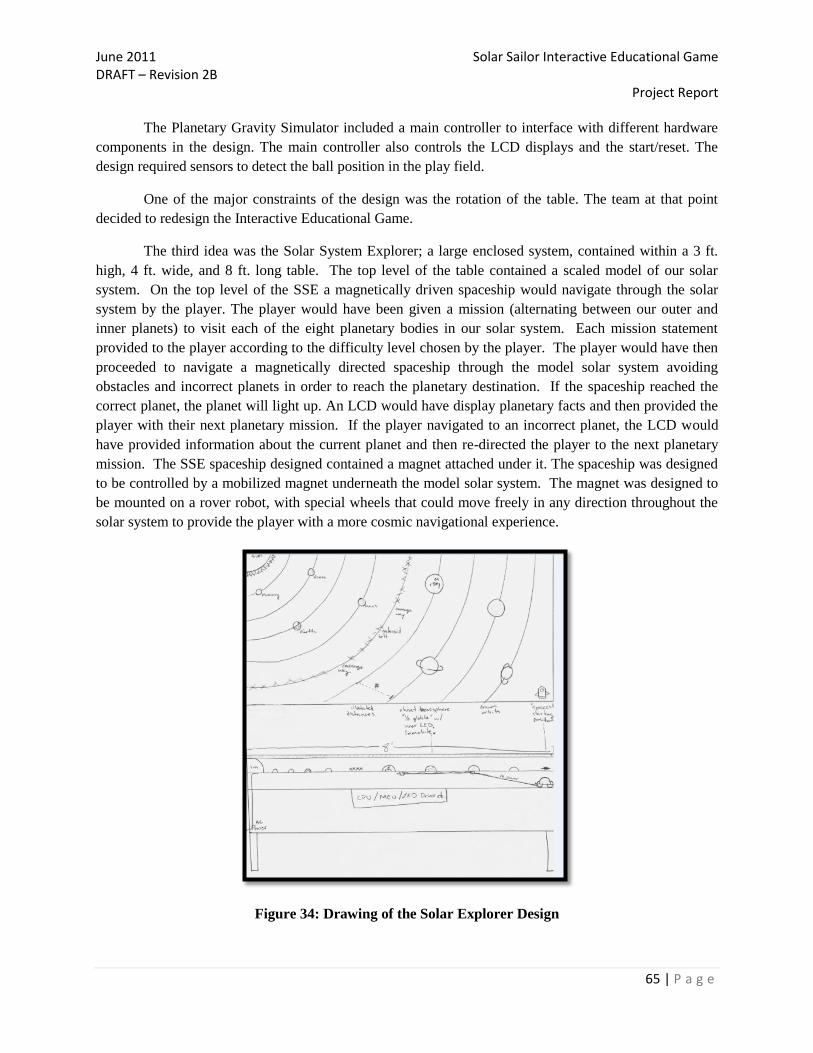
June 2011 Solar Sailor Interactive Educational Game DRAFT – Revision 2B Project Report
65 | P a g e
The Planetary Gravity Simulator included a main controller to interface with different hardware
components in the design. The main controller also controls the LCD displays and the start/reset. The
design required sensors to detect the ball position in the play field.
One of the major constraints of the design was the rotation of the table. The team at that point
decided to redesign the Interactive Educational Game.
The third idea was the Solar System Explorer; a large enclosed system, contained within a 3 ft.
high, 4 ft. wide, and 8 ft. long table. The top level of the table contained a scaled model of our solar
system. On the top level of the SSE a magnetically driven spaceship would navigate through the solar
system by the player. The player would have been given a mission (alternating between our outer and
inner planets) to visit each of the eight planetary bodies in our solar system. Each mission statement
provided to the player according to the difficulty level chosen by the player. The player would have then
proceeded to navigate a magnetically directed spaceship through the model solar system avoiding
obstacles and incorrect planets in order to reach the planetary destination. If the spaceship reached the
correct planet, the planet will light up. An LCD would have display planetary facts and then provided the
player with their next planetary mission. If the player navigated to an incorrect planet, the LCD would
have provided information about the current planet and then re-directed the player to the next planetary
mission. The SSE spaceship designed contained a magnet attached under it. The spaceship was designed
to be controlled by a mobilized magnet underneath the model solar system. The magnet was designed to
be mounted on a rover robot, with special wheels that could move freely in any direction throughout the
solar system to provide the player with a more cosmic navigational experience.
Figure 34: Drawing of the Solar Explorer Design
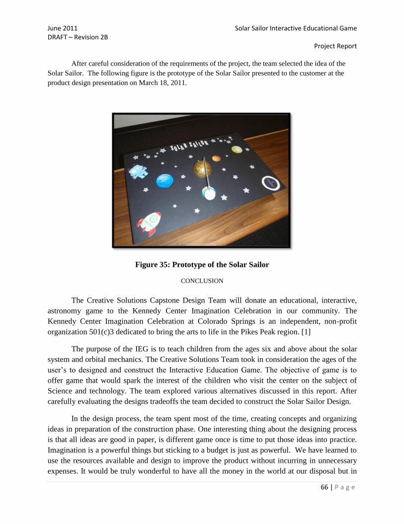
June 2011 Solar Sailor Interactive Educational Game DRAFT – Revision 2B Project Report
66 | P a g e
After careful consideration of the requirements of the project, the team selected the idea of the
Solar Sailor. The following figure is the prototype of the Solar Sailor presented to the customer at the
product design presentation on March 18, 2011.
Figure 35: Prototype of the Solar Sailor
CONCLUSION
The Creative Solutions Capstone Design Team will donate an educational, interactive,
astronomy game to the Kennedy Center Imagination Celebration in our community. The
Kennedy Center Imagination Celebration at Colorado Springs is an independent, non-profit
organization 501(c)3 dedicated to bring the arts to life in the Pikes Peak region. [1]
The purpose of the IEG is to teach children from the ages six and above about the solar
system and orbital mechanics. The Creative Solutions Team took in consideration the ages of the
user‟s to designed and construct the Interactive Education Game. The objective of game is to
offer game that would spark the interest of the children who visit the center on the subject of
Science and technology. The team explored various alternatives discussed in this report. After
carefully evaluating the designs tradeoffs the team decided to construct the Solar Sailor Design.
In the design process, the team spent most of the time, creating concepts and organizing
ideas in preparation of the construction phase. One interesting thing about the designing process
is that all ideas are good in paper, is different game once is time to put those ideas into practice.
Imagination is a powerful things but sticking to a budget is just as powerful. We have learned to
use the resources available and design to improve the product without incurring in unnecessary
expenses. It would be truly wonderful to have all the money in the world at our disposal but in

June 2011 Solar Sailor Interactive Educational Game DRAFT – Revision 2B Project Report
67 | P a g e
the real world, every project has its constraints and requirements. One of the project‟s
requirements was to build the Solar Sailor within the budget of $800.00, in the design process we
realize that requirement would not be met, and we stand at $1899.45 including the parts donated
by team members (See Appendix/Part List). It is important to keep in mind that the budget for
building a prototype or conducting a proof-of-concept is not the same budget and cost of
building the final product. The team had to revise the original parts list to include items that
were needed after the original design. If the Solar Sailor were to be sent to production the cost of
the materials will be reduced since the correct parts and amounts will be clearly stated and the
building process also revised.
In addition to the parts list is important to mention the quantity of hours worked on this
project. The team used an excel spreadsheet to account for all activities related to the project.
Some team members worked mostly in the design and administration of the project and others in
the construction and logistics of the game. Overall the team spent 493.50 hours in the design and
administration and 521.50 hours in the construction.
Communication is the key for the success of any design. The Creative Solutions team
reviewed all current and past activities to allow each team member to understand what have been
done and improvements that were necessary. At the beginning of the Product Design series, the
team went to the storming phase, the team struggled in the first weeks of the project to
disseminate information and clarification was often delivered in the classroom. One way that the
communication improved within the team, was the use of the “Dropbox” software. The use of
the “Dropbox” software proved vital, not only could a team member update a document without
creating a new version, but it provided a logical method of storing information.
Recommendations for further design and construction the overall system is 85 percent
complete. The electronics have been installed and there will be additional testing to ensure the
safety and reliability of the Solar Sailor IEG. In addition several pieces will be replaced due to
mechanical failures. The wheels to ensure portability have been removed due to the weight of the
game console. Sliders have been provided instead. In the process of transporting the game
console back to the construction site, the top unit was damaged due to strong winds.
In summary, the product design series has been a challenging and rewarding experience
for the members of the Creative Solutions Team. The knowledge gathered from this experience
will help each member in their future careers in the aspects ranging from team dynamics, design
specifications and requirements, budget constraints and most importantly the Ethical obligation
as future engineers to provide a product to our customer.

June 2011 Solar Sailor Interactive Educational Game DRAFT – Revision 2B Project Report
68 | P a g e
References
[1] n.d. The Kennedy Center. Imagination Celebration. Information Pamphlet. 1515 N Academy Blvd. Suite 200,
Colorado Springs, CO 80909.
[2] Khandani,S. (2005) Engineering Design Process. Education Transfer Plan. Retrieved from:
http://www.iisme.org/etp/HS%20Engineering-%20Engineering.pdf on May 24, 2011.
[3] MIT/LL Labs (2005) – AUST-1 Manual. Safety Considerations and regulations.
[4] Novak, J. (2005) Game Development Essentials. 2nd
Edition. Cengage Learning. Information published at
http://theinteractivelearningcenter.com/
[5] Halliday, D. (2001) Physics Volume I. New York New York: John Wiley & Sons.
[6] Serway, R. (2004) Physics for Scientists and Engineers. Sixth edition. Brooks/Cole.
[7] Thomas, R. (2006) The Analysis and Design of Linear Circuits. . Hoboken, NJ: John Wiley & Sons
[8] McGraw-Hill Science & Technology Dictionary, Circular Object. Retrieved from
http://www.answers.com/topic/circular-orbit on March 10, 2011
[9] Honeywell Datasheet. HMC6042 2-Axis Mag Sensor Circuit .Honeywell 12001 Highway 55 Plymouth, MN
55441 Tel: 800-323-8295 www.honeywell.com/magneticsensors
[10] http://www.solarbotics.net/starting/200111_dcmotor/200111_dcmotor2.html
[11] DC Motor: High Torque Mini DC Gear Motor 3-12V, 5-25 rpm for Hobby / Robots (Batteryspace.com)
[12] Pulse-width modulation. Stemmler, H. (August 1964). "Geregelter Drehstrom-Umkehrantrieb mit gesteuertem
Umrichter nach dem Unterschwingungsverfahren". BBC Mitteilungen (Brown Boveri et Cie) 51 (8/9): 555–577.
Retrieved from http://en.wikipedia.org/wiki/Pulse-width_modulation
[13] Culbertson, F. (2001). Diagrams, Space Shuttle. NASA. http://history.nasa.gov/SP-
4225/diagrams/shuttle/shuttle-diagram-1.htm. Retrieved 16 March 2011.
[14] Schaffran, M. (2003) Inverter Buffered H-Bridges. Solarbotics.net. Information published at http://
http://www.solarbotics.net/library/circuits/driver_buf_h.html/ Retrieved 16 March 2011.
[15] Seale, E. (2003) The "Miller" Solar Engine. Solarbotics.net. Information published at
http://www.solarbotics.net/library/circuits/se_t1_mse.html. Retrieved 16 March 2011.
[16] Solarbotics. Tiny Pager Motor. http://www.solarbotics.com/products/tpm2/. Retrieved 16 March 2011
[17] STS01DTP06. (2006). Datasheet, Dual NPN-PNP complementary Bipolar Transistor. STMicroelectronics.
http://www.st.com/stonline/books/pdf/docs/11404.pdf. Retrieved 16 March 2011
[18] L4931ABxx, L4931Cxx. (2008) Datasheet, Very Low Drop Voltage Regulators With Inhibit.
STMicroelectronics.
http://www.st.com/internet/com/TECHNICAL_RESOURCES/TECHNICAL_LITERATURE/DATASHEET/C
D00000971.pdf. Retrieved 16 March 2011.
[19] 74HC240; 74HCT240. (2007). Datasheet, Octal Buffer/Line Driver; 3-State; Inverting. NXP B.V.
http://www.nxp.com/documents/data_sheet/74HC_HCT240.pdf. Retrieved 16 March 2011
[20] L4931ABxx...
[21] AM-HRR30-XXX. (2004). Datasheet, Miniature AM Super-Regen Receiver. RFSolutions Ltd.
http://www.rfsolutions.co.uk/acatalog/DS014-1.pdf. Retrieved 16 March 2011.
[22] ATtiny20. (2010). Datasheet, 8-bit AVR Microcontroller with 2K Bytes In-System Programmable Flash.
Atmel Corporation. http://www.atmel.com/dyn/resources/prod_documents/8235S.pdf. Retrieved 16 March
2011.
[23] Fasco model B45267 centrifugal blower. Retrieved on 14 March 2010 from the Electric Motor Warehouse
website: http://www.electricmotorwarehouse.com/fasco/fasco_blower.htm
[24] Mechatronics MD1238X fan. Retrieved on 14 March 2010 from the Cooler Guys website:
http://www.coolerguys.com/840556021698.html
[25] Tyco T9A Series relay. Retrieved on 15 March 2010 from the Sparkfun website:
http://www.sparkfun.com/products/101
[26] Panasonic DK Series relay. Retrieved on 16 March 2010 from the Digikey website:
http://search.digikey.com/scripts/DkSearch/dksus.dll?Detail&name=255-2053-ND
[27] Diablotek 250W Power Supply. Retrieved on 16 March 2010 from the NewEgg website:
http://www.newegg.com/Product/Product.aspx?Item=N82E16817822006&nm_mc=OTC-
Froogle&cm_mmc=OTC-Froogle-_-Power+Supplies-_-Diablotek-_-17822006
[28] http://wrw51.wordpress.com/2008/02/21/understanding-compressed-air-cfm-psi-force-flow/

June 2011 Solar Sailor Interactive Educational Game DRAFT – Revision 2B Project Report
69 | P a g e
[29] http://www.ehow.com/how-does_5347986_air-hockey-tables-work.html
[30] http://www.fasco.com/pdf/CentrifugalBlowers_2008.pdf
[31] http://www.mechatronics.com/pdf/MD1238.pdf
[30] http://www.gcaudio.com/resources/howtos/loudness.html
[31] http://www.sparkfun.com/tutorials/119
[32]http://pewa.panasonic.com/assets/pcsd/catalog/dk-catalog.pdf
[33]http://www.sparkfun.com/datasheets/Components/T9A_DS.pdf
[34]http://www.newegg.com/Product/Product.aspx?Item=N82E16817822006&nm_mc=OTC-
Froogle&cm_mmc=OTC-Froogle-_-Power+Supplies-_-Diablotek-_-17822006
[35] (n.d) Document #281. For Kids‟ sake: Think Toy Safety from the Consumer Product Safety Commission,
Office of Information and Public Affairs, 4330 East West Highway, Bethesda, MD 20814
[36] (2010) EPA Identifies Noise Levels Affecting Health and Welfare. Retrieved from: epa.gov/history/topics/noise
on March 16, 2011.
[37] (2011) Pulse-width modulation tutorial. Schönung, A.; Stemmler, H. (August 1964). "Geregelter Drehstrom-
Umkehrantrieb mit gesteuertem Umrichter nach dem Unterschwingungsverfahren". BBC Mitteilungen (Brown
Boveri et Cie) 51 (8/9): 555–577. Retrieved from: http://en.wikipedia.org/wiki/Pulse-width_modulation
[38] Therrel, J. (2002) Age Determination Guidelines Relating to Children‟s Age to Toy Charactersistics and Play
Behavior. Retrieved from: www.cpsc.gov/businfo.adg.pdf