SOLAR SAIL PERFORMANCE REQUIREMENTS FOR SOLAR SAIL PERFORMANCE REQUIREMENTS FOR MISSIONS TO THE...
9
55th International Astronautical Congress 2004 - Vancouver, Canada SOLAR SAIL PERFORMANCE REQUIREMENTS FOR MISSIONS TO THE OUTER SOLAR SYSTEM AND BEYOND Bernd Dachwald German Aerospace Center (DLR), Institute of Space Simulation, Linder Hoehe, 51147 Cologne [email protected] ABSTRACT Solar sails enable missions to the outer solar system and beyond, although the solar radiation pressure decreases with the square of solar distance. For such missions, the solar sail may gain a large amount of energy by first making one or more close approaches to the sun. Within this paper, optimal trajectories for solar sail missions to the outer planets and into near interstellar space (200AU) are presented. Thereby, it is shown that even near/medium-term solar sails with relatively moderate performance allow reasonable transfer times to the boundaries of the solar system. INTRODUCTION Utilizing solely the freely available solar radiation pressure for propulsion, solar sails make a wide range of high-ΔV missions feasible. They enable even missions to the outer solar system and beyond, despite the fact that the solar radiation pressure decreases with the square of the sun–sail distance. Sauer observed that the solar sail may gain a large amount of energy by making a close approach to the sun, turning the trajectory into a hyperbolic one [1], a maneuver for which Leipold coined the term ’solar photonic assist’ (SPA) [2, 3]. Sauer made parametric studies for near-interstellar mis- sions to 100 AU, 250 AU and 1000 AU using ideal 1 very-high-performance solar sails that perform only a single SPA [4]. Leipold observed that solar sails with a more conservative performance require mul- tiple SPAs to achieve solar system escape. He gave some (non-optimized) example trajectories for ideal solar sails but made no parametric studies. Within this paper, optimal trajectories for solar sail missions to the outer planets and into near inter- stellar space (200 AU) are presented, both for ideal and for non-ideal 2 sails. It will be shown that – even for near/medium-term solar sails with rela- tively moderate performance – multiple SPA tra- jectories allow reasonable transfer times (without the need to perform any gravity assist maneuver). 1 where the incident radiation is reflected specularly 2 where a fraction of the incoming radiation is absorbed and a fraction of the reflected radiation is reflected non- specularly Nevertheless, without the use of additional propul- sive devices and/or an aerocapture maneuver at the target, only fast flybys can be accomplished due to the associated large hyperbolic excess velocities. For the calculation of near-globally optimal tra- jectories, evolutionary neurocontrol is used, a novel method that is based on artificial neural networks and evolutionary algorithms [5, 6, 7]. SOLAR SAIL FORCE MODELS For describing the solar radiation pressure (SRP) force exerted on a solar sail, it is convenient to in- troduce two unit vectors. The first one is the sail normal vector n, which is perpendicular to the sail surface and always directed away from the sun. Its direction, which describes the sail attitude, is ex- pressed by the sail clock angle α and the sail cone angle β (Fig. 1). Fig. 1: Definition of the sail normal vector 1 IAC-04-S.P.11
Transcript of SOLAR SAIL PERFORMANCE REQUIREMENTS FOR SOLAR SAIL PERFORMANCE REQUIREMENTS FOR MISSIONS TO THE...
55th International Astronautical Congress 2004 - Vancouver, Canada
SOLAR SAIL PERFORMANCE REQUIREMENTS FOR
MISSIONS TO THE OUTER SOLAR SYSTEM AND BEYOND
Bernd Dachwald
German Aerospace Center (DLR), Institute of Space Simulation, Linder Hoehe, 51147 Cologne
ABSTRACT
Solar sails enable missions to the outer solar system and beyond, although the solar
radiation pressure decreases with the square of solar distance. For such missions, the
solar sail may gain a large amount of energy by first making one or more close approaches
to the sun. Within this paper, optimal trajectories for solar sail missions to the outer
planets and into near interstellar space (200AU) are presented. Thereby, it is shown that
even near/medium-term solar sails with relatively moderate performance allow reasonable
transfer times to the boundaries of the solar system.
INTRODUCTION
Utilizing solely the freely available solar radiationpressure for propulsion, solar sails make a widerange of high-∆V missions feasible. They enableeven missions to the outer solar system and beyond,despite the fact that the solar radiation pressuredecreases with the square of the sun–sail distance.Sauer observed that the solar sail may gain a largeamount of energy by making a close approach tothe sun, turning the trajectory into a hyperbolicone [1], a maneuver for which Leipold coined theterm ’solar photonic assist’ (SPA) [2, 3]. Sauermade parametric studies for near-interstellar mis-sions to 100 AU, 250AU and 1000 AU using ideal1
very-high-performance solar sails that perform onlya single SPA [4]. Leipold observed that solar sailswith a more conservative performance require mul-tiple SPAs to achieve solar system escape. He gavesome (non-optimized) example trajectories for idealsolar sails but made no parametric studies.
Within this paper, optimal trajectories for solarsail missions to the outer planets and into near inter-stellar space (200 AU) are presented, both for idealand for non-ideal2 sails. It will be shown that –even for near/medium-term solar sails with rela-tively moderate performance – multiple SPA tra-jectories allow reasonable transfer times (withoutthe need to perform any gravity assist maneuver).
1where the incident radiation is reflected specularly2where a fraction of the incoming radiation is absorbed
and a fraction of the reflected radiation is reflected non-specularly
Nevertheless, without the use of additional propul-sive devices and/or an aerocapture maneuver at thetarget, only fast flybys can be accomplished due tothe associated large hyperbolic excess velocities.
For the calculation of near-globally optimal tra-jectories, evolutionary neurocontrol is used, a novelmethod that is based on artificial neural networksand evolutionary algorithms [5, 6, 7].
SOLAR SAIL FORCE MODELS
For describing the solar radiation pressure (SRP)force exerted on a solar sail, it is convenient to in-troduce two unit vectors. The first one is the sailnormal vector n, which is perpendicular to the sailsurface and always directed away from the sun. Itsdirection, which describes the sail attitude, is ex-pressed by the sail clock angle α and the sail coneangle β (Fig. 1).
Fig. 1: Definition of the sail normal vector
1
IAC-04-S.P.11

55th International Astronautical Congress 2004 - Vancouver, Canada
The second unit vector is the thrust unit vectorf , which points always along the direction of theSRP force. Its direction is described likewise by thethrust clock angle γ and the thrust cone angle δ(Fig. 2).
Fig. 2: Definition of the thrust vector
At a distance r from the sun, the SRP is
P =S0
c
(r0
r
)2
= 4.563µNm2
·(r0
r
)2
where S0 = 1368 W/m2 is the solar constant, c isthe speed of light in vacuum, and r0 = 1 AU.
For the optical characteristics of a solar sail, dif-ferent assumptions can be made, which result indifferent models for the magnitude and direction ofthe SRP force acting on the sail. The most simplemodel assumes a specularly reflecting sail surface.The SRP force on such an ideal sail of area A is
FSRP = 2PA cos2 β n (1)
Thus, the SRP force it is always along the directionof the sail normal vector, f = n.
Another SRP force model that is widely encoun-tered uses an overall sail efficiency factor η ≤ 1 withthe intention of describing the non-ideal reflectivityof the sail. Using this factor, the SRP force actingon the sail is
FSRP = 2ηPA cos2 β n (2)
Also for this model, the SRP force is always alongthe direction of the sail normal vector, f = n.Therefore, this model also describes a specularly re-flecting sail surface, where the angle of incidence isequal to the angle of reflection. From the perspec-tive of trajectory analysis, this models is equivalentto the ideal sail model because a decrease of η canalways be offset with an inversely proportional in-crease of A. Therefore, this model is not furtherconsidered here.
Because the surface of a real solar sail is nota specular reflector, a thorough trajectory simu-lation must consider the optical characteristics ofthe real sail film, as they can be parameterized bythe absorption coefficient α, the reflection coeffi-cient ρ, the transmission coefficient τ , and the emis-sion coefficient ε, with the constraint α + ρ + τ =1. The reflection coefficient can be further di-vided into a coefficient for specular reflection ρs,a coefficient for diffuse reflection ρd, and a coef-ficient for back reflection ρb, with the constraintρs + ρd + ρb = ρ. The non-ideal solar sail forcemodel used within this paper considers the opticalparameters P = {α, ρs, ρd, ρb, τ, εf , εb} of a sail filmthat is aluminum-coated on the front side (emissiv-ity εf = 0.05) and chromium-coated on the back side(emissivity εb = 0.55) to keep the sail temperaturewithin moderate limits3. Using the non-ideal solarsail force model, the SRP force has a component
F⊥ = 2PAq⊥(β,P)
perpendicular to the sail surface and a component
F‖ = 2PAq‖(β,P)
parallel to the sail surface.Using the optical parameters for an Al|Cr-coated
sail [8], one gets
q⊥(β,PAl|Cr) = 0.9136 cos2 β − 0.005444 cos β
q‖(β,PAl|Cr) = 0.0864 sinβ cos β
The SRP force may be written as
FSRP =√
F 2⊥ + F 2
‖ f
and by defining
Q2(β,P) =√
q2⊥(β,P) + q2
‖(β,P)
as
FSRP = 2PAQ2(β,P) f (3)
Thus, the SRP force is not along the direction ofthe sail normal vector (except for β = 0). The anglebetween n and f is
ε = arctan(q‖/q⊥)
SOLAR SAIL ORBITAL DYNAMICS
The orbital dynamics of solar sails is in many re-spects similar to the orbital dynamics of other
3as it will become clear later from equation (4)
2

55th International Astronautical Congress 2004 - Vancouver, Canada
low-thrust spacecraft. Other low-thrust spacecraft,however, may orient its thrust vector into any de-sired direction, whereas the thrust vector of a solarsail is constrained to lie on the surface of a bubblethat is always directed away from the sun (Fig. 3).Nevertheless, by controlling the sail orientation rel-ative to the sun, a solar sail can gain orbital angu-lar momentum and spiral outwards – away from thesun – or lose orbital angular momentum and spiralinwards – towards the sun.
Fig. 3: Spiralling towards and away from the sun
For SPA trajectories, the minimal flight time de-pends not only on the lightness of the solar sail butalso on the minimal solar distance along the tra-jectory (see Fig. 5). The smaller the minimal solardistance, the larger the amount of energy that canbe gained during a SPA. The sail’s equilibrium tem-perature at a distance r from the sun is
T =(
1− ρ
εf + εb
S0
σ
r20
r2cos β
)1/4
∝ cos1/4 β
r1/2(4)
where σ is the Stefan-Boltzmann constant [9].Therefore, the minimal distance to the sun is – fora given sail attitude – limited by the temperaturelimit of the sail film.
Trajectory optimization for SPA trajectories isexceedingly difficult because one must not only be-ware of flying too close to the sun but one mustalso take care that the trajectory becomes not hy-perbolic too early, so that no additional energy canbe gained. At the same time, one must find the opti-mal trade-off between the time that is spent withinthe inner solar system – to gain energy – and thetime that is required to fly outwards after the tra-jectory became hyperbolic.
SOLAR SAIL PERFORMANCEPARAMETERS
The following performance parameters are com-monly used to describe the lightness of solar sails:
The sail assembly loading is defined as themass of the sail assembly (the sail film and the re-quired structure for storing, deploying and tension-ing the sail, index ’SA’) per unit area:
σSA =mSA
A(5)
The sail assembly loading is the key parameter forthe efficiency of the solar sail’s structural design.
The sailcraft loading, the key parameter for thelightness of the entire solar sailcraft, is defined asthe specific mass of the sailcraft including the pay-load (index ’PL’), where the term payload standsfor the total sailcraft except the solar sail assembly(i.e., except the propulsion system):
σ =m
A=
mSA + mPL
A= σSA +
mPL
A(6)
The characteristic acceleration is an equiva-lent parameter for expressing the lightness of theentire solar sailcraft. It is defined as the SRP accel-eration acting on a solar sail that is oriented per-pendicular to the sun-line at 1 AU:
ac =2S0/c ·A · q⊥(0,P)
m=
Peff,0(P) ·Am
=Peff,0(P)
σSA + mPL/A(7)
For an Al|Cr-coated sail, Peff,0(PAl|Cr) = 2S0/c ·q⊥(0,PAl|Cr) = 8.288 µN/m2.
SOLAR SAIL TRAJECTORYOPTIMIZATION
Within this paper, evolutionary neurocontrol(ENC) is used for the calculation of near-globallyoptimal trajectories. This method is based on arti-ficial neural networks (ANNs) and evolutionary al-gorithms (EAs). ENC attacks trajectory optimiza-tion problems from the perspective of artificial in-telligence and machine learning. Here, it can onlybe sketched how this method is used to search op-timal solar sail trajectories. The reader who is in-terested in the details of the method is referred toRefs. [5, 6, 7].
The problem of searching an optimal solar sailtrajectory x?[t] = (r?[t], r?[t]), where ’[t]’ denotesthe time history of the preceding variable, is equiv-alent to the problem of searching an optimal sail
3

55th International Astronautical Congress 2004 - Vancouver, Canada
normal vector history n?[t], as it is defined by theoptimal time history of the so-called direction unitvector d?[t], a unit vector that points along the op-timal thrust direction. Within the context of ma-chine learning, a trajectory is regarded as the resultof a sail steering strategy S that maps the prob-lem relevant variables (the solar sail state x andthe target state xT) onto the direction unit vector,S : {x,xT} ⊂ R12 7→ {d} ⊂ R3, from which n is cal-culated. This way, the problem of searching x?[t]is equivalent to the problem of searching (or learn-ing) the optimal sail steering strategy S?. An ANNmay be used as a so-called neurocontroller (NC) toimplement solar sail steering strategies. It can beregarded as a parameterized function Nπππ (the net-work function) that is – for a given network topol-ogy – completely defined by the internal parameterset πππ of the ANN. Therefore, each πππ defines a sailsteering strategy Sπππ. The problem of searching x?[t]is therefore equivalent to the problem of searchingthe optimal NC parameter set πππ?. EAs that workon a population of strings can be used for findingπππ? because πππ can be mapped onto a string ξ (alsocalled chromosome or individual). The trajectoryoptimization problem is solved when the optimalchromosome ξ? is found. Fig. 4 sketches the sub-sequent transformation of a chromosome into a so-lar sail trajectory. An evolutionary neurocontroller(ENC) is a NC that employs an EA for learning (orbreeding) the optimal sail steering strategy.�
���
chromosome/individual/string ξ=
NC parameter set πππ
��
��
NC network function N=
sail steering strategy S
�� ��sail normal vector history n[t]
�� ��solar sail trajectory x[t]
?
?
?
Fig. 4: Transformation of a chromosome into a solarsail trajectory
ENC was implemented by the author within alow-thrust trajectory optimization program calledInTrance, which stands for Intelligent Trajectoryoptimization using neurocontroller evolution. In-Trance is a smart global trajectory optimization
method that requires only the target body/stateand intervals for the initial conditions as input tofind a near-globally optimal trajectory for the spec-ified problem. It works without an initial guess anddoes not require the attendance of a trajectory op-timization expert.
RESULTS
The gravitational forces of all celestial bodies, theSRP force, and disturbing forces are influencing themotion of solar sails. Ideally, all these forces have tobe considered for a thorough mission analysis. Formission feasibility analysis, however, as it is donewithin this paper, the following simplifications arevalid: (1) the solar sail is moving under the soleinfluence of solar gravitation and radiation, (2) thesun is a point mass and a point light source, (3) thesolar sail attitude can be changed instantaneously,and (4) the optical characteristics of the sail film donot degrade over time.
All trajectories calculated within this paper as-sume direct interplanetary insertion of the solar sailwith zero hyperbolic excess energy (C3 = 0km2/s2).To find the absolute flight time minima – inde-pendent of the actual constellation of Earth andthe respective target – no flyby at the target it-self but only a crossing of its orbit within a dis-tance of less than 106 km is required, and In-Trance is allowed to vary the launch date withina one year interval. Therefore, the resulting flighttimes represent lower bounds that are strictly validonly for the optimal constellation of Earth andthe respective target. Specific suboptimal launchdates/constellations might yield much longer flighttimes.
Before calculating minimal flight times for mis-sions to all outer planets and into near interstel-lar space (200 AU), a Neptune flyby mission willbe used to assess the general features of SPA tra-jectories, to compare different solar sail force mod-els (ideal vs. non-ideal solar sails), and to comparedifferent optimization constraints (limitation of al-lowed minimal solar distance vs. limitation of al-lowed maximal sail temperature).
1. Dependency of Minimal Flight Time onLightness and Minimal Solar Distance forIdeal Solar Sails
For a Neptune flyby, InTrance was used to calculateminimal flight times for ideal solar sails with differ-ent characteristic accelerations and different solardistance limits. Fig. 5 shows the results. As ex-pected, the trajectories are faster for lighter solar
4

55th International Astronautical Congress 2004 - Vancouver, Canada
Fig. 5: Flight time over minimal solar distance for dif-ferent characteristic accelerations
sails and for sails that are allowed to make closerapproaches to the sun. Interestingly, the flight timeobeys approximately a linear law for all three val-ues of ac. Figs. 7 and 8 show optimal Neptune flybytrajectories for four different characteristic accelera-tions, the allowed minimal solar distance being lim-ited to 0.1 AU in all four cases. One can see thatmore and more SPAs are required as the character-istic acceleration of the sail decreases.
2. Ideal vs. Non-Ideal Solar Sails
In the previous section, minimal flight times havebeen presented for ideal solar sails because, to theauthors knowledge, all previous solar sail trajectoryanalyses for solar system escape missions assumeideal reflectivity of the sail. A real solar sail, how-ever, is not an ideal reflector and a thorough tra-jectory analysis must take into account the opticalcharacteristics of the real sail film [10]. In Fig. 6,flight times are compared for an ideal and a non-ideal solar sail with ac = 1.0 mm/s2. Fig. 6 showsthat the flight times are about 5% longer, if the non-ideal reflectivity of the sail is taken into account.
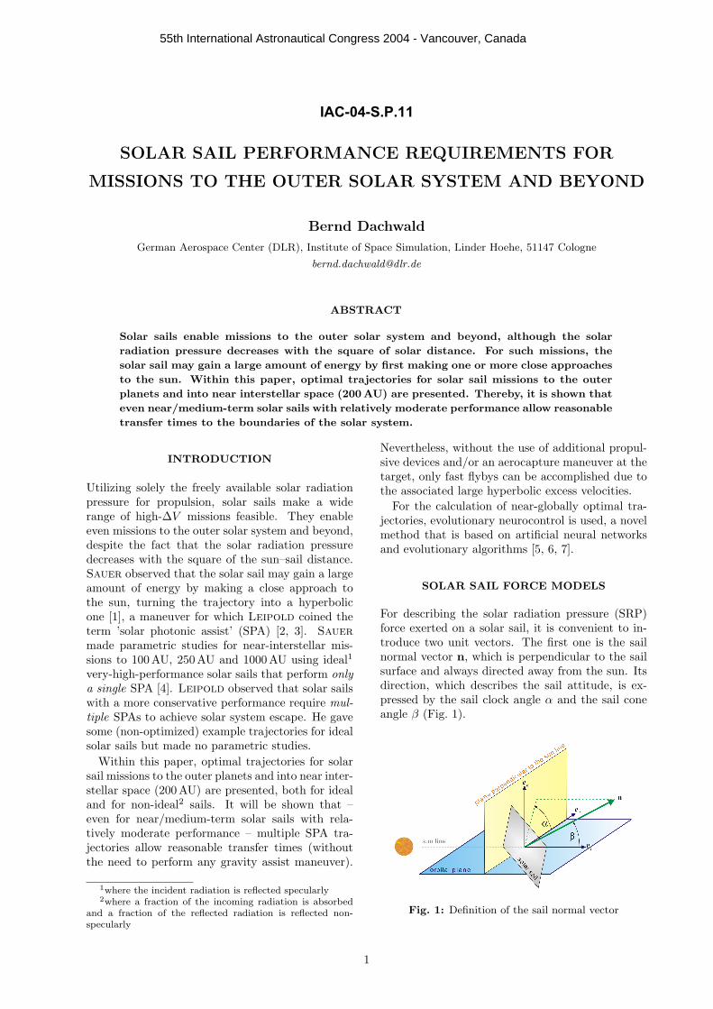
3. Distance-Limited vs. Temperature-LimitedTrajectories
From now on, it will become necessary to distin-guish trajectories, for which the allowed minimalsolar distance was constrained, from trajectories,for which the allowed maximal sail film tempera-ture was constrained. Therefore, let rlim denote theallowed minimal solar distance (distance limit) and
Fig. 6: Comparison of minimal flight times for idealand non-ideal solar sails
rmin the minimal solar distance along the trajec-tory, and let Tlim denote the allowed maximal sailfilm temperature (sail temperature limit) and Tmax
the maximal sail film temperature along the trajec-tory. Using this notation, Tmax = Tmax(rlim) (fordistance-limited trajectories) and rmin = rmin(Tlim)(for temperature-limited trajectories).
In previous papers by Leipold [2, 3] andSauer [4], rlim was used as a path constraint forthe trajectory optimization of ideal solar sails, withthe argument that such a constraint enforces thatsome Tlim will not be exceeded during the closest so-lar approach.4 According to equation (4), however,the temperature at a given solar distance r dependsalso on the light incidence angle β. It might there-fore yield faster trajectories, if not rlim but Tlim isdirectly used as a path constraint. This can berealized by constraining the sail attitude so thatthe light incidence angle can not become smallerthan the critical one, β > βlim(r, Tlim), where Tlim
would be exceeded. Fig. 9 shows two exemplary tra-jectories, one distance-limited (Fig. 9(a)) and onetemperature-limited (Fig. 9(b)).
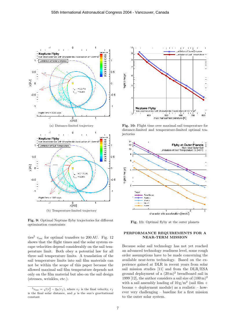
By keeping β large enough during the closestapproach, the temperature-limited trajectory ap-proaches the sun closer while maintaining the sailtemperature below the temperature that is given bythe distance-limited trajectory (so that Tmax is thesame for both trajectories). The resulting trajec-tory is faster than the distance-limited one. Fig. 10shows that for a given Tlim, optimal temperature-limited trajectories are on average about 5% faster
4although – strictly – the temperature of an ideal sail isalways 0K according to equation (4)
5

55th International Astronautical Congress 2004 - Vancouver, Canada
(a) ac = 2.0mm/s2, one solar photonic assist
(b) ac = 1.0mm/s2, two solar photonic assists
Fig. 7: Topology of optimal Neptune flyby trajectoriesfor different characteristic accelerations
than optimal distance-limited ones. Interestingly,the flight time and and the maximal sail temper-ature are nearly inversely proportional for bothcurves.
4. Minimal Flight Times to the Outer Planetsand Near Interstellar Space
Fig. 11 shows the minimal flight times for opti-mal temperature-limited flyby trajectories to theouter planets using a non-ideal solar sail. Thesail film temperature was limited to Tlim = 240◦C.Interestingly, the flight time obeys nearly a poten-tial law for all targets. Even near-term solar sails
(a) ac = 0.75 mm/s2, three solar photonic assists
(b) ac = 0.5mm/s2, four solar photonic assists
Fig. 8: Topology of optimal Neptune flyby trajectoriesfor different characteristic accelerations
(ac ≈ 0.4 mm/s2) are able to reach Uranus withinless than 10 years, and even medium-term solar sails(ac ≈ 0.6 mm/s2) are able to reach Neptune and theinner Edgeworth-Kuiper belt within less than 10years.
5. Dependency of Minimal Flight Time on SailTemperature Limit for Non-Ideal Solar Sails
Fig. 12 shows for three different sail temperaturelimits (200◦C, 240◦C, and 280◦C) the minimal flighttimes and the achieved solar system escape veloci-
6
55th International Astronautical Congress 2004 - Vancouver, Canada
(a) Distance-limited trajectory
(b) Temperature-limited trajectory
Fig. 9: Optimal Neptune flyby trajectories for differentoptimization constraints
ties5 vesc for optimal transfers to 200 AU. Fig. 12shows that the flight times and the solar system es-cape velocities depend considerably on the sail tem-perature limit. Both obey a potential law for allthree sail temperature limits. A translation of thesail temperature limits into sail film materials cannot be within the scope of this paper because theallowed maximal sail film temperature depends notonly on the film material but also on the sail design(stresses, wrinkles, etc.).
5vesc =√
(v2f − 2µ/rf ), where vf is the final velocity, rf
is the final solar distance, and µ is the sun’s gravitationalconstant
Fig. 10: Flight time over maximal sail temperature fordistance-limited and temperature-limited optimal tra-jectories
Fig. 11: Optimal flyby at the outer planets
PERFORMANCE REQUIREMENTS FOR ANEAR-TERM MISSION
Because solar sail technology has not yet reachedan advanced technology readiness level, some roughorder assumptions have to be made concerning theavailable near-term technology. Based on the ex-perience gained at DLR in recent years from solarsail mission studies [11] and from the DLR/ESAground deployment of a (20m)2 breadboard sail in1999 [12], the author considers a sail size of (100 m)2
with a sail assembly loading of 10 g/m2 (sail film +booms + deployment module) as a realistic – how-ever very challenging – baseline for a first missionto the outer solar system.
7

55th International Astronautical Congress 2004 - Vancouver, Canada
Fig. 12: Optimal transfer to 200AU
For a square sail, equation (7) gives
ac =Peff,0
σSA + mPL/s2(8)
One can see that the characteristic acceleration de-pends on three design parameters, the sail assem-bly loading σSA, the payload mass mPL, and thesail side length s (or sail area s2), defining a three-dimensional solar sailcraft design space. Figs. 13and 14 show parametric sections of this design spacefor a fixed σSA = 10 g/m2 and for a fixed s = 100 m,respectively. One can read from Fig. 13 that a max-imal characteristic acceleration of 0.829 mm/s2 canbe achieved without any payload. For a lower char-acteristic acceleration, some payload can be accom-modated, depending on the sail size. To achieveac > 0.829 mm/s2, the sail assembly loading has tobe reduced below 10 g/m2 (Fig. 14).
Fig. 13: Characteristic acceleration as a function of sand mPL for σSA = 10 g/m2
Fig. 14: Characteristic acceleration as a function of σSA
and mPL for s = 100m
For an exemplary payload of mPL = 100 kg, acharacteristic acceleration of 0.4144 mm/s2 couldbe achieved (see Fig. 13). According to Fig. 11,this is sufficient to reach the inner Edgeworth-Kuiper-belt within less than 13 years. For ac =0.4144 mm/s2, Fig. 15 shows the trade-off betweensail size and sail assembly loading for various val-ues of mPL. One can see that for mPL = 100 kg areduction of the sail assembly loading yields only asmall decrease in sail size, whereas an increase inthe sail assembly loading requires a much larger so-lar sail. For σSA ' 19.5 g/m2, the sail becomes tomassive to achieve ac = 0.4144 mm/s2 even withoutany payload.
8

55th International Astronautical Congress 2004 - Vancouver, Canada
Fig. 15: Sail side length that is required to achieveac = 0.4144mm/s2 as a function of σSA and mPL
SUMMARY AND CONCLUSIONS
The material presented within this paper providestrajectory and performance trade-offs for missionsto the outer solar system and into near interstel-lar space (200 AU). Minimal flight times have beengiven for different solar sail performance levels. Forthe 200 AU-mission, also different maximal sail tem-peratures have been investigated and the achievedsolar system escape velocities have been given. Tothe authors knowledge, all previous trajectory anal-yses for solar system escape missions have been car-ried out for ideal high-performance sails. Withinthis paper, optimal trajectories have been presentedalso for non-ideal solar sails and for near/medium-term solar sails with a relatively moderate perfor-mance. It was shown that a thorough trajectoryanalysis must consider the non-ideal reflectivity ofthe solar sail, which yields minimal flight times thatare about 5% longer than those of ideal sails. To theauthors knowledge, all previous trajectory analysesfor solar system escape missions constrain the mini-mal solar distance to enforce that some sail temper-ature limit will not be exceeded during the closestsolar approach. The trajectories calculated withinthis paper demonstrate that about 5% faster trajec-tories can be obtained, if not the allowed minimalsolar distance but the allowed maximal sail tem-perature is directly used as an optimization con-straint. A near/medium-term (100 m)2 solar sailwith a specific mass of 10 g/m2 would be able totransport a payload of 100 kg to Uranus within lessthan 10 years or to the inner Edgeworth-Kuiperbelt within less than 13 years.
References
[1] C.G. Sauer. Optimum solar-sail interplanetarytrajectories. San Diego, USA, August 1976.AIAA/AAS Astrodynamics Conference. 76-792.
[2] M. Leipold and O. Wagner. ’Solar photonic assist’trajectory design fo solar sail missions to the outersolar system and beyond. Greenbelt, USA, May1998. AAS/GSFC 13th International Symposiumon Space Flight Dynamics.
[3] M. Leipold. To the sun and Pluto with solar sailsand micro-sciencecraft. Acta Astronautica, 45(4-9):549–555, 1999.
[4] C.G. Sauer. Solar sail trajectories for solar polarand interstellar probe missions. In K.C. Howell,F.R. Hoots, and B. Kaufman, editors, Astrodynam-ics 1999, volume 103 of Advances in the Astronau-tical Sciences, pages 547–562. Univelt, Inc., 2000.
[5] B. Dachwald. Low-Thrust Trajectory Optimizationand Interplanetary Mission Analysis Using Evolu-tionary Neurocontrol. Doctoral thesis, Universitatder Bundeswehr Munchen; Fakultat fur Luft- undRaumfahrttechnik, 2004.
[6] B. Dachwald. Optimization of interplanetary solarsailcraft trajectories using evolutionary neurocon-trol. Journal of Guidance, Control, and Dynamics,27(1):66–72.
[7] B. Dachwald. Evolutionary neurocontrol: Asmart method for global optimization of low-thrust trajectories. Providence, USA, August 2004.AIAA/AAS Astrodynamics Specialist Conference.AIAA-2004-5405.
[8] J. L. Wright. Space Sailing. Gordon and BreachScience Publishers, Philadelphia, 1992.
[9] C.R. McInnes. Solar Sailing. Technology, Dynam-ics and Mission Applications. Springer–Praxis Se-ries in Space Science and Technology. Springer–Praxis, Berlin, Heidelberg, New York, Chicester,1999.
[10] B. Dachwald. Minimum transfer times for nonper-fectly reflecting solar sailcraft. Journal of Space-craft and Rockets, 41(4):693–695.
[11] W. Seboldt and B. Dachwald. Solar sail (WP 01-80). Technical report, ESA Propulsion 2000 Pro-gram (Phase II), 2003. Final Report Issue 1.
[12] W. Seboldt, M. Leipold, M. Rezazad, L. Herbeck,W. Unkenbold, D. Kassing, and M. Eiden. Ground-based demonstration of solar sail technology. Riode Janeiro, Brazil, 2000. 51st International Astro-nautical Congress. IAF-00-S.6.11.
9