SOLAR BOOST™ 2000E - pdf.wholesalesolar.com pdf folder/SB2000EManual.pdf · CHARGER LOCATION &...
15
SOLAR BOOST™ 2000E 25A 12V MAXIMUM POWER POINT TRACKING PHOTOVOLTAIC CHARGE CONTROLLER INSTALLATION AND OPERATION MANUAL THIS MANUAL INCLUDES IMPORTANT SAFETY INSTRUCTIONSFOR MODEL SB2000E SAVE THESE INSTRUCTIONS COVERED UNDER US PATENT 6,111,391 © RV Power Products, Inc 2003 430-0012 E
Transcript of SOLAR BOOST™ 2000E - pdf.wholesalesolar.com pdf folder/SB2000EManual.pdf · CHARGER LOCATION &...

SOLAR BOOST™ 2000E25A 12V MAXIMUM POWER POINT TRACKING
PHOTOVOLTAIC CHARGE CONTROLLER
INSTALLATION AND OPERATION
MANUAL
THIS MANUAL INCLUDES IMPORTANTSAFETY INSTRUCTIONSFOR MODEL SB2000E
SAVE THESE INSTRUCTIONS
COVERED UNDER US PATENT 6,111,391
© RV Power Products, Inc 2003 430-0012 E
RV Power Products - Solar Boost 2000E
1
TABLE OF CONTENTSIMPORTANT SAFETY INSTRUCTIONS.............................................................................. 2
PRODUCT DESCRIPTION................................................................................................... 3Part Numbers And Options ...................................................................................... 3
OPERATION .................................................................................................................... 3Two Stage Charge Control....................................................................................... 4
Bulk Charge ................................................................................................ 4Constant Voltage Charge............................................................................ 4
Charge Status Indicator ........................................................................................... 4Optional Temperature Compensation...................................................................... 5Equalization.............................................................................................................. 6Maximum Power Point Tracking (MPPT)................................................................. 6
Typical Current Boost Performance............................................................ 7How MPPT And Current Boost Works........................................................ 7
INSTALLATION .................................................................................................................... 8Over Voltage / Reverse Polarity Protection.............................................................. 8Electrostatic Handling Precautions .......................................................................... 8Enabling Temperature Compensation ..................................................................... 8Charge Voltage ........................................................................................................ 9Maximum Power Voltage ......................................................................................... 9
Optimizing MPPT ........................................................................................ 9Solar Boost 2000E Installation ................................................................................. 9System Wiring.......................................................................................................... 10
SPECIFICATIONS ................................................................................................................ 12
THREE YEAR LIMITED WARRANTY .................................................................................. 12
TROUBLESHOOTING GUIDE ............................................................................................ 13
TABLES AND FIGURESTable 1 Charge Status Indicator........................................................................ 5Table 2 Typical Current Boost Performance ..................................................... 7Table 3 Maximum One Way Wire Length For Less Than 0.42V Drop.............. 11Figure 1 Panel Layout......................................................................................... 4Figure 2 Charge Voltage -vs.- Battery Temperature .......................................... 5Figure 3 Setup Adjustments and Field Connections .......................................... 10Figure 4 Preferred Wiring Method ...................................................................... 11Figure 5 Mounting Template............................................................................... 14
RV Power Products, Inc.2598 Fortune Way, Suite K
Vista CA, 92083, USA
800-493-RVPP •••• 760-597-1642 •••• Fax 760-597-1731www.rvpowerproducts.com

Installation and Operation Manual
2
IMPORTANT SAFETY INSTRUCTIONSThis manual contains important instructions for Model SB2000E
SAVE THESE INSTRUCTIONS
1. Refer installation and servicing to qualified service personnel. Incorrect installation or use may result in risk ofelectric shock or fire. No user serviceable parts in this unit.
2. PERSONAL PRECAUTIONSa) Working in the vicinity of lead-acid batteries is dangerous. Batteries produce explosive gasses during normal
battery operation.b) To reduce risk of battery explosion, follow these instructions and those published by battery manufacturer and
manufacturer of any equipment you intend to use in vicinity of battery.c) Someone should be within range of your voice or close enough to come to your aid when you work near a lead-
acid battery.d) Have plenty of fresh water and soap nearby in case battery acid contacts skin, clothing or eyes.e) Wear complete eye protection and clothing protection. Avoid touching eyes while working near battery.f) If battery acid contacts skin or clothing, wash immediately with soap and water. If acid enters eye, immediately
flood eye with running cold water for at least 10 minutes and get medical attention immediately.g) NEVER SMOKE or allow a spark or flame in vicinity of battery.h) Be extra cautious to reduce risk of dropping metal tool onto battery. It might spark or short circuit battery or
other electrical part that may cause explosion.i) Remove personal metal items such as rings, bracelets and watches when working with a lead-acid battery. A
lead-acid battery can produce a short circuit current high enough to weld a ring or the like to metal, causing asevere burn.
j) Remove all sources of power, photovoltaic and battery before servicing or installing.
3. CHARGER LOCATION & INSTALLATIONa) This unit is designed to charge flooded or sealed type lead-acid chemistry batteries. Follow battery
manufacturers charging recommendations when considering this unit for use with other battery chemistry, i.e.,NiCd.
b) This unit employs components that tend to produce arcs or sparks. NEVER install in battery compartment or inthe presence of explosive gases.
c) This unit must be installed and wired in accordance with National Electrical Code, ANSI/NFPA 70.d) Over current protection for the battery must be provided externally. To reduce the risk of fire, connect to a circuit
provided with 30 amperes maximum over current protection in accordance with National Electrical Code,ANSI/NFPA 70.
e) Insure that unit is properly configured for the battery being charged.f) Unit is not water tight. Do not expose to rain or snow.g) Insure all terminating connections are clean and tight.h) Charging system must be properly installed as described in these instructions prior to operation.i) Do not connect to a PV array capable of producing greater than 20 amps of short circuit current @ 25°C.
4. PREPARING TO CHARGEa) Never charge a frozen battery.b) Be sure battery is mounted in a well ventilated compartment.c) Add distilled water in each cell of a lead-acid battery until battery acid reaches level specified by battery
manufacturer. This helps purge excessive gas from the cells. Do not overfill. For batteries other than floodedlead-acid type, or sealed batteries without cell caps, carefully follow manufacturers charging instructions.

RV Power Products - Solar Boost 2000E
3
PRODUCT DESCRIPTIONSolar Boost™ 2000E is a 12 volt 25 amp fully automatic, very high performance Maximum Power Point
Tracking (MPPT) photovoltaic (PV) charge controller. Through the use of patented MPPT technology, Solar Boost2000E can increase charge current up to 30% or more. A high accuracy digital display is also provided to monitor PVcharge performance. The controller is fully protected against voltage transients, reverse polarity, and overloadconditions.
Solar Boost 2000E employs series pass Pulse Width Modulation (PWM) charge voltage control. Precise PWMvoltage control leads to a more fully charged battery, with longer life and less maintenance. Solar Boost 2000E alsoincludes automatic electronic current limit which allows you to use the full 25 amp capability without worrying aboutoverload or nuisance fuse blow from excessive current. A manual equalize function is also included to periodicallycondition liquid electrolyte lead-acid batteries. The PWM control system uses highly efficient and reliable powerMOSFET transistors. The MOSFET’s are turned on and off at high frequency to precisely control charge voltage andMPPT. An environmentally sealed high current high reliability relay is used to disconnect the PV array at night toprevent unwanted current drain. A relay is used rather than blocking diodes for improved power conversion efficiencyand MPPT current boost performance. The relay is not stressed by functioning as part of the voltage control systemand continually turning on and off as with other PV controllers. It simply turns on in the morning and off in the evening,and in this application has a life expectancy in excess of 105 operations.
Fully automatic temperature compensation of charge voltage is available as an option to further improvecharge control, battery performance and battery life. The available SensorLug™ battery temperature sensor is built forlong term reliability. The sensor element is environmentally sealed and encapsulated into a copper lug which mountsdirectly to the battery terminal. Order the SensorLug with 20ft/6.1m of cable as RVPP part number 930-0022-20.
PART NUMBERS AND OPTIONS• SB2000E ........................ Solar Boost 2000E with digital display• 930-0022-20................... SensorLug™ battery temperature sensor with 20’ cable• 720-0011-01................... Wall mount box for SB2000E
OPERATIONCharge control and MPPT current boost operations are fully automatic. Charge turns on whenever the PV
array is capable of producing approximately 0.15 amps at @ 14 volts. Note that there must be a battery in thesystem with a minimum voltage of 10 volts or greater for the Solar Boost 2000E to operate. Electronic current limitprevents the possibility of overload by limiting output current to 25 amps regardless of available PV input current orinput power.
The highly accurate digital display consumes very little power and is always on and available for use. Asshown in Figure 1, the display can be selected to show Solar Panel Current, Output Charge Current or BatteryVoltage. Solar Panel Current displays current in amps flowing from the solar array to Solar Boost 2000E, whereasOutput Charge Current displays current in amps flowing from Solar Boost 2000E to the battery. When MPPT currentboost is functioning, Output Charge Current will be greater than Solar Panel Current. If operating conditions aresuch that PV output power is insufficient for MPPT current boost to function, Output Charge Current may show 0.1amps less than Solar Panel Current. This is normal as Solar Boost 2000E consumes approximately 0.090 amps tooperate when PV charge is on. When PV charge is off, standby current consumption is quite low at approximately0.017 amps.
Battery Voltage is measured at the Solar Boost 2000E battery terminals. Although the measurement systemis highly accurate, displayed voltage will be somewhat higher than actual battery terminal voltage when high chargecurrent is being delivered to the battery. This is due to voltage drop in the wires between the Solar Boost 2000E andbattery. Error during charge can be minimized by using large low resistance wiring.

Installation and Operation Manual
4
The front panel serves as a heat sink for power control devices. Itis normal for the front panel to be warm during operation.
PANEL LAYOUT
Figure 1
TWO STAGE CHARGE CONTROLSolar Boost 2000E charges the battery in a two stage charge process, bulk and constant voltage. A third
manually initiated equalization mode is also available to periodically condition liquid electrolyte lead-acid batteries.
Bulk Charge
Solar Boost 2000E will be in the bulk charge stage when the battery is at a low state of charge, typically lessthan 90% full. Solar Boost 2000E delivers as much charge current as possible during bulk to recharge the battery asrapidly as possible. Maximum charge current varies with the number and size of solar panels installed, availablesolar energy, and operation of the proprietary MPPT current boosting system. Battery voltage increases as thebattery recovers charge in the bulk stage. When the battery recovers sufficient charge for battery voltage to reach thecharge voltage setpoint, the system switches to the constant voltage stage. During the bulk charge stage, the ChargeStatus LED will be on continuously.
Constant Voltage Charge
Once the battery becomes more than approximately 90% charged, the system changes to a constant voltagemode and the Charge Status LED blinks. The charge voltage setpoint is factory calibrated to approximately 14.0 volts.While charge voltage is held constant, charge current slowly decreases as the last 10% or so of battery capacity isrestored. If there was no DC load on the system, output current from Solar Boost 2000E would eventually drop toapproximately the battery amp-hour rating divided by 500, or approximately 0.5 amps for a 230 amp-hour battery.The precision PWM voltage control method provided by Solar Boost 2000E prevents over charge while maintaininga more fully charged battery.
CHARGE STATUS INDICATORA Charge Status indicator LED is provided on the Solar Boost 2000E panel. For small scale solar electric
systems where the Solar Boost 2000E is typically used, an excellent indication of a highly charged battery is when theSolar Boost 2000E is able to hold the battery at the desired charge voltage. These systems usually consist of 75 – 400watts of solar power, and charge a battery bank in the range of 200 – 800 amp-hours. With sufficient sun and the

RV Power Products - Solar Boost 2000E
5
battery under light load so that there is at least 1 amp of net charge current per 100 amp-hours of battery capacity, thesystem will show the battery to be charged when the battery is greater than approximately 90 – 95% full. When theCharge Status LED blinks showing the Solar Boost 2000E to be in the constant voltage mode, the battery is consideredcharged.
If solar power generation is too low and/or load current is too high for there to be at least 1 amp of net chargecurrent available per 100 amp-hours of battery capacity the Solar Boost 2000E may be unable to hold battery voltage atthe desired charge voltage setpoint. This will cause a discharged condition to be displayed even though the battery maybe highly charged. A charged condition will again be displayed if sufficient net charge current becomes available andthe battery is indeed charged. A smaller battery and/or larger solar array will tend to show a charged condition sooner.
CHARGE STATUS INDICATOR
INDICATORACTION
CHARGEMODE
TYPICAL BATTERY STATEOF CHARGE
OFF CHARGE OFFNO SOLAR INPUT
NOT DISPLAYED
CONTINUOUSLY ON BULK LESS THAN 90% FULL
BLINKING2 SEC ON / 2 SEC OFF
CONSTANT VOLTAGE GREATER THAN 90% FULL
BLINKING RAPIDLY0.2 SEC ON / 0.2 SEC OFF
EQUALIZE N/A
Table 1
OPTIONAL TEMPERATURE COMPENSATIONThe charge voltage required by lead-acid batteries changes with battery temperature. Temperature
compensation of charge voltage leads to increased battery life and decreased battery maintenance. If your systemincludes the optional battery temperature sensor (p/n 930-0022-20), charge voltage will continuously adjust to theproper value based on measured battery temperature. Both liquid and gel electrolyte 12 volt lead-acid batteriesrequire the same compensation characteristic of –30.0 millivolts/°C. The graph of Figure 2 shows charge voltagesetpoint vs. battery temperature for the factory setting of 14.0 volts @ 80°F. The slope of curve remains constant fordifferent 80°F voltage settings. As described in the installation section, Solar Boost 2000E can also provide thenecessary –20.0 millivolts/°C compensation curve for NiCd (10 cell) batteries.
CHARGE VOLTAGE SETPOINT -VS.- BATTERY TEMPERATURE
Figure 2

Installation and Operation Manual
6
EQUALIZATION
WARNING: Not all batteries can be safely equalized. Equalization shouldonly performed on vented liquid electrolyte lead-acid batteries. Followbattery manufacturers recommendations pertaining to equalization.
Equalization is essentially a controlled over charge and should only be performed on vented liquid electrolytelead-acid batteries. Since each cell of a battery is not identical, repeated charge/discharge cycles can lead to animbalance in the specific gravity of individual battery cells. Stratification of the electrolyte can also occur. Equalizationbrings all battery cells up to the same specific gravity, and eliminates stratification by heavily gassing the battery.Periodic equalization per the battery manufacturers recommendations will greatly improve battery performance and life.Most batteries fail due to sulfation, which periodic equalization helps to prevent.
A proper equalization cycle is a substantial over charging of the battery at relatively high voltages withsignificant battery gassing. Solar Boost 2000E features a manually operated equalization function since an operatorshould always plan and monitor the process. The operator should ensure that equipment connected to the battery cantolerate the high equalization voltage which will be applied to the battery, and that the battery attains the proper voltagefor the desired time period. Battery voltage setpoint during equalization will be the present charge voltage setpoint plus1.2 volts or 15.2 volts for the factory calibrated charge voltage setpoint of 14.0 volts. Note that with temperaturecompensation, the equalization voltage can be quite high at cool temperatures.
As shown in Figure 1, the blue equalization push-button is located on the front of the Solar Boost 2000E panel.Equalization is enabled when the push-button is in, and the Charge Status LED blinks rapidly. Equalization is normallyconducted approximately once per month, with the battery held at the equalization voltage for a period of approximatelytwo hours. It is best to equalize a battery that is already fully charged so that the desired equalization voltage is reachedquickly. Following the desired equalization period, the equalization cycle is terminated and normal charge operation isresumed by again pressing the equalization push-button. The battery should then be topped off with distilled water perthe battery manufacturers recommendations.
Equalization works best with a relatively large PV array. This is because approximately 2.8 amps of chargecurrent per 100 amp-hours of battery capacity is required to actually drive battery voltage up to the desired 15.2 volts @80°F. This means at least 12 amps of charge current is needed to properly equalize a 440 amp-hour battery. Even ifyour solar array is too small to drive battery voltage up to the desired 15.2 volts, substantial benefit will be realized byperiodically applying an increased charge voltage for several hours once a month.
MAXIMUM POWER POINT TRACKING (MPPT)MPPT and associated current boost operation is fully automatic and will function whenever sufficient PV
voltage and current are available. The percent increase you will receive in Output Charge Current relative to SolarPanel Current is variable, and will change with operating conditions. When conditions are such that sufficient PVvoltage and current are not available to produce an increase in output current, Solar Boost 2000E will operate as a highperformance series pass PWM controller. Boost performance can be easily monitored using the digital display.Whenever Output Charge Current is greater than Solar Panel Current, MPPT current boost is functioning. A minimumPV current of just under one amp is required before MPPT can begin to operate.
The principal operating conditions which affect current boost performance are battery voltage and PV arraytemperature. At constant solar intensity the power available from a PV array changes with PV array temperature. A PVarray’s power vs. temperature characteristic is such that a cool PV array can produce a higher voltage, and thereforemore power, than a hot PV array. When PV voltage is sufficiently high for MPPT to operate, Solar Boost 2000E deliversa constant power output to the battery. Since output power is essentially constant while MPPT is operating, a decreasein battery voltage produces a corresponding increase in charge current. This means that the greatest current increaseoccurs with a combination of cool ambient temperature and low battery voltage. Solar Boost 2000E delivers the highestcharge current increase when you need it most, in cold weather with a discharged battery.

RV Power Products - Solar Boost 2000E
7
Because output power is constant while MPPT is operating, anything that leads to lower battery voltage willproduce an increase in Output Charge Current. While a discharged battery is one way to produce lower output voltage,and therefore higher output current, other normal conditions may produce lower voltage as well. Any 12 volt powerconsumption during the day will decrease net battery charge current, which decreases battery voltage.
TYPICAL CURRENT BOOST PERFORMANCE
As described above current boost performance for a particular installation varies with PV array temperatureand battery voltage. Two of the other primary factors which affect boost performance include system wiring and PVpanel design. The effect wiring has on performance is that power wasted heating undersized wiring becomesunavailable for charging. The effect PV panel design has on performance is that panels with a maximum power voltage(VMP) of 17 volts or greater will tend to produce more boost, whereas PV panels with VMP less than 17 volts will tend toproduce less boost. Additionally, more PV panels will tend to produce more boost, whereas fewer PV panels will tend toproduce less boost.
For a system using four 75 watt PV panels with peak power specifications of 4.45 amps @ 17 volts @ 25°C,representative boost performance under a variety of operating conditions is shown in Table 2. Your current boostperformance will vary due to a variety of factors. What you can be sure of is that Solar Boost 2000E will automaticallydeliver the highest charge current possible for a given installation and set of operating conditions.
TYPICAL CURRENT BOOST PERFORMANCEFOUR 75 WATT PV PANELS
BATTERY CONDITIONAND VOLTAGE
AMBIENTCONDITIONS
PV INPUTCURRENT
OUTPUT CHARGECURRENT
PERCENTINCREASE
FULLY DISCHARGED10.9V
35°FEARLY MORNING
8.8 AMPS 12.1 AMPS 38%
HIGHLY CHARGED13.8V
45°FCLOUDY, BREEZY
7.9 AMPS 9.3 AMPS 18%
HIGHLY DISCHARGED11.8V
65°FCLEAR, STILL AIR
16.7 AMPS 18.4 AMPS 10%
HIGHLY CHARGED13.8V
75°FCLEAR, STILL AIR
18.5 AMPS 18.5 AMPS 0%
TABLE 2
HOW MPPT AND CURRENT BOOST WORKS
A PV panel is a constant current type device. As shown on a typical PV panel voltage vs. current curve, currentremains relatively constant over a wide range of voltage. A typical 75 watt panel is specified to deliver 4.45 amps @ 17volts @ 25°C. Traditional PV controllers essentially connect the PV array directly to the battery when battery voltage islow. When this 75 watt panel is connected directly to a battery charging at 12 volts, the PV panel still providesapproximately the same current. But, because PV output voltage is now held at 12 volts by the battery rather than 17volts, it only delivers 53 watts to the battery. This wastes 22 watts of available power.
Solar Boost 2000E’s patented MPPT technology operates in a very different fashion. Under these conditionsSolar Boost 2000E calculates the maximum power voltage (VMP) at which the PV panel delivers its maximum availablepower, in this case 17 volts. It then operates the PV panel at 17 volts which extracts maximum power from the PVpanel. Solar Boost 2000E continually recalculates the maximum power voltage as operating conditions change. This isreferred to as Maximum Power Point Tracking (MPPT).
Input power from the MPPT controller, in this case 75 watts, feeds a switching type power converter whichreduces the 17 volt input to battery voltage at the output. The full 75 watts which is now being delivered at 12 voltswould produce a charge current of 6.25 amps. A charge current increase of 1.8 amps or 40% is achieved by convertingthe 22 watts that would have been wasted into useable charge current. Note that this example assumes 100%

Installation and Operation Manual
8
efficiency to illustrate the principal of operation. In actual operation, boost will be somewhat less as some availablepower is lost in wiring, connections, fuse and in Solar Boost 2000E.
INSTALLATIONWARNING: Read, understand and follow the Important Safety Instructions inthe beginning of this manual before proceeding. Over current protection forthe battery must be provided externally. To reduce the risk of fire, connect to acircuit provided with 30 amperes maximum over current protection inaccordance with National Electrical Code, ANSI/NFPA 70.
IMPORTANT: Solar Boost 2000E is not protected against and will bedamaged by reverse battery connection to the PV terminals. Install in adry non-corrosive environment. Damage due to reverse batteryconnection to the PV terminals, corrosion, or adjustments or connectionsother than those shown in Figure 3 void the limited warranty.
OVER VOLTAGE / REVERSE POLARITY PROTECTIONSolar Boost 2000E is protected against reverse polarity and high voltage transients for both the PV array and
the battery. If the battery is connected reverse polarity, Solar Boost 2000E will not operate and there will be nothingshown on the display. If the PV array is connected reverse polarity, Solar Boost 2000E will not provide output currentand the PV input current display will show negative current. Should high PV current be available during reverse PVconnection, the front panel will become quite warm. High reverse PV current applied for an extended period maydamage the Solar Boost 2000E and is not covered by the limited warranty.
ELECTROSTATIC HANDLING PRECAUTIONSWhile transient voltage protection is provided for terminal block connections, exposed circuits may be
damaged by electrostatic discharge during installation and handling. Discharge yourself by touching a water faucet orother electrical ground prior to handling the unit and avoid touching components on the circuit board. Keep Solar Boost2000E in it’s electrostatic protective bag until the unit is installed. All electronic circuits may be damaged by staticelectricity and these instructions combined with special packaging are provided to minimize the possibility of damage.The risk of electrostatic damage is highest when relative humidity drops below 40%.
ENABLING TEMPERATURE COMPENSATIONFor temperature compensation to operate, the SensorLug battery temperature sensor must be installed and
temperature compensation must be enabled. The sensor is electrically isolated and mounts directly to any batteryterminal. Note that connections are polarized (red/black), and must be connected as shown in Figure 3.
SWITCH3
SWITCH4
TEMPERATURE COMPENSATION
OFF OFF DISABLEDON ON LEAD-ACID BATTERY –30.0 millivolts/°CON OFF NiCd (10cell) –20.0 millivolts/°C
WARNING: Solar Boost 2000E cannot control battery voltage iftemperature compensation is enabled with the sensor installedreverse polarity. Additionally, output current will be disabled iftemperature compensation is enabled with the sensor not installed.

RV Power Products - Solar Boost 2000E
9
CHARGE VOLTAGEThe factory setting of approximately 14.0 volts is suitable for most liquid electrolyte batteries and does not
require adjustment. For a predominately float application, a somewhat lower voltage of perhaps 13.8 volts may bebeneficial in decreasing water loss. For a heavily cycling application, a somewhat higher voltage of perhaps 14.5 voltsmay be beneficial in decreasing charge time and increasing amp-hours delivered. The adjustment potentiometerlocation is shown in Figure 3. With the Charge Status LED blinking indicating that the battery at or near full charge,adjust the charge voltage as desired. If optional temperature compensation option is installed, first turn switches #3 & 4off to disable temperature compensation. Adjust the charge voltage to the desired 80°F value, and then turntemperature compensation back on.
The charge voltage setpoint is calibrated by adjusting actual battery charge voltage as displayed on the unit.Setting charge voltage therefore requires that the battery be at or near full charge so that the unit is actually controllingbattery voltage. This can sometimes be hard to achieve when battery capacity is large compared to available solarcharge current. Charge Voltage Calibration Tool P/N 930-0031-01 as described in technical bulletin #100209 simplifiescharge voltage calibration be eliminating the need to have the battery be highly charged. To access this and othertechnical bulletins, see the RV Power Products internet web site at www.rvpowerproducts.com.
MAXIMUM POWER VOLTAGEThe nominal setting for this adjustment is the difference between the PV panel’s open circuit voltage (VOC)
and maximum power voltage (VMP). These voltage values are typically listed on both the PV panel datasheet and onthe rating label affixed to each PV panel. This value needs to be set correctly for the MPPT system to delivermaximum current boost. The factory setting is 4.4 volts which is the appropriate value for many popular 36 cell PVpanels. These panels typically list VOC at ≈21.4 volts and VMP at ≈17.0 volts, which yields; 21.4V - 17.0V = 4.4V.
OPTIMIZING MPPT
As indicated above, the peak power voltage setting (VOC – VMP) is a nominal value. The combined effects ofmanufacturing tolerances in the PV panel and wiring resistance in a particular installation can sometimes shift theoptimum setting. While not required, it is recommended that for maximum boost performance this adjustment befine tuned following installation. This is a one time setup and does not require seasonal adjustment. Fine tuning isalso desirable following installation of additional PV panels or other substantial system change.
Fine tuning is easily accomplished by slowly adjusting the MPPT adjust potentiometer to obtain maximumOutput Charge Current. Adjustment is best done in near full sun with a discharged battery and cool ambienttemperatures. The red MPPT Active LED above the potentiometer turns on when MPPT is functioning andadjustment can be made. Verify that the LED remains on at the maximum current adjustment point, and as youcheck for a slight drop in current on either side of the maximum point. If LED does not remain on, MPPT is notoperating due to a combination of high PV temperature and/or high battery voltage. MPPT can usually be made tooperate by lowering battery voltage through application of a heavy DC load. If in doubt, leave the adjustment at thefactory default position of midway between 11:00 and 12:00 o’clock as shown in Figure 3. Note that the LED brieflyturns off every 10 seconds while the system recalculates the MPPT operating point.
SOLAR BOOST 2000E INSTALLATIONThe Solar Boost 2000E panel should be mounted in a dry location that provides easy routing of large size wires
to the PV array and battery, and keeps PV/battery wire length as short as practical. The location should also providefree air circulation around the front of the panel, and if possible, around the rear. Take great care not to damage circuitboard components as this damage is not covered under the limited warranty. Figure 5 provides a 1:1 template for thepanel cut-out. A surface mounting box is also available as RVPP part number 720-0011-01.
IMPORTANT: The front panel serves as a heat sink for power control devicesand requires free air circulation for cooling. Do not enclose the front panelbehind a tight fitting door or otherwise substantially restrict air flow.
Installation and Operation Manual
10
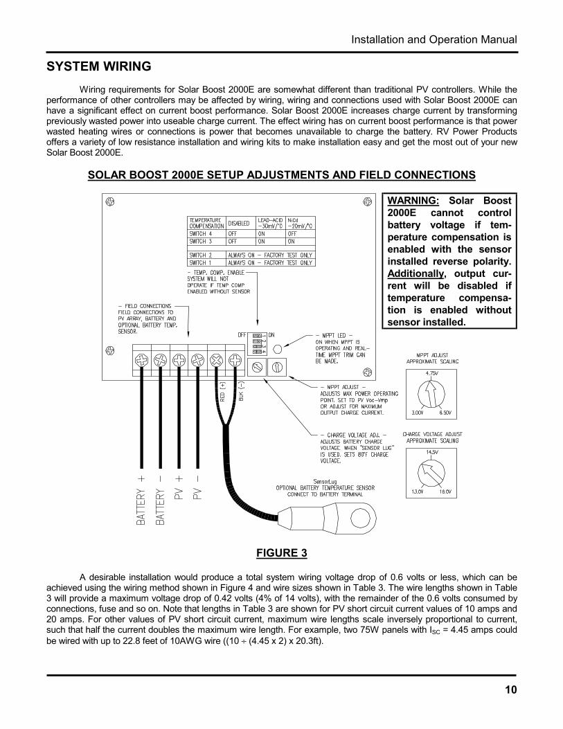
SYSTEM WIRINGWiring requirements for Solar Boost 2000E are somewhat different than traditional PV controllers. While the
performance of other controllers may be affected by wiring, wiring and connections used with Solar Boost 2000E canhave a significant effect on current boost performance. Solar Boost 2000E increases charge current by transformingpreviously wasted power into useable charge current. The effect wiring has on current boost performance is that powerwasted heating wires or connections is power that becomes unavailable to charge the battery. RV Power Productsoffers a variety of low resistance installation and wiring kits to make installation easy and get the most out of your newSolar Boost 2000E.
SOLAR BOOST 2000E SETUP ADJUSTMENTS AND FIELD CONNECTIONS
FIGURE 3
A desirable installation would produce a total system wiring voltage drop of 0.6 volts or less, which can beachieved using the wiring method shown in Figure 4 and wire sizes shown in Table 3. The wire lengths shown in Table3 will provide a maximum voltage drop of 0.42 volts (4% of 14 volts), with the remainder of the 0.6 volts consumed byconnections, fuse and so on. Note that lengths in Table 3 are shown for PV short circuit current values of 10 amps and20 amps. For other values of PV short circuit current, maximum wire lengths scale inversely proportional to current,such that half the current doubles the maximum wire length. For example, two 75W panels with ISC = 4.45 amps couldbe wired with up to 22.8 feet of 10AWG wire ((10 ÷ (4.45 x 2) x 20.3ft).
WARNING: Solar Boost2000E cannot controlbattery voltage if tem-perature compensation isenabled with the sensorinstalled reverse polarity.Additionally, output cur-rent will be disabled iftemperature compensa-tion is enabled withoutsensor installed.
RV Power Products - Solar Boost 2000E
11
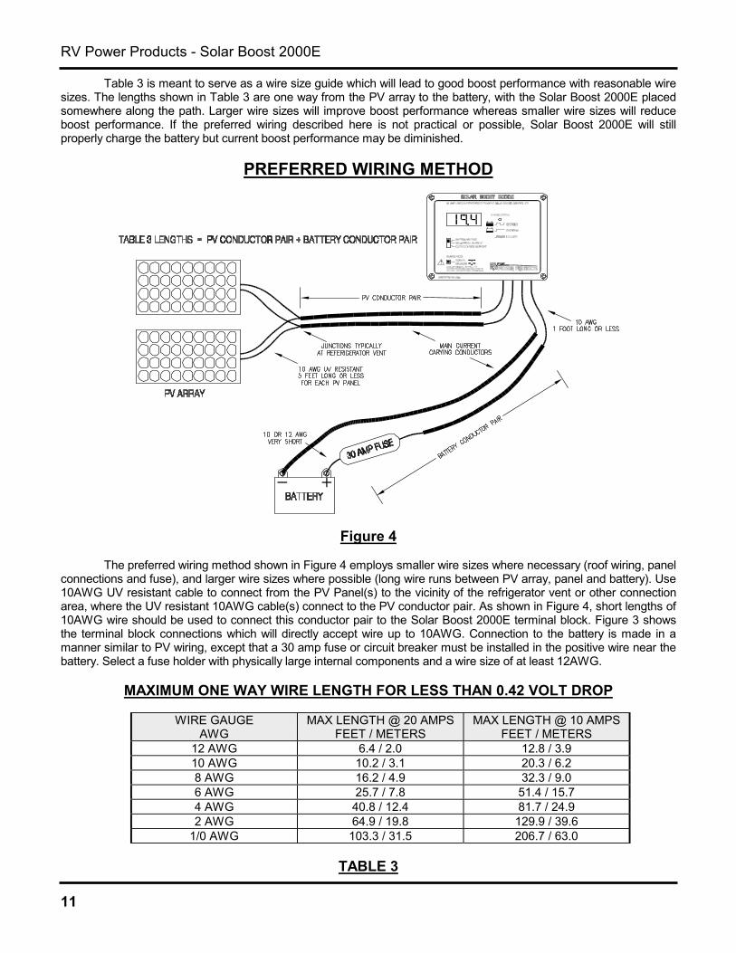
Table 3 is meant to serve as a wire size guide which will lead to good boost performance with reasonable wiresizes. The lengths shown in Table 3 are one way from the PV array to the battery, with the Solar Boost 2000E placedsomewhere along the path. Larger wire sizes will improve boost performance whereas smaller wire sizes will reduceboost performance. If the preferred wiring described here is not practical or possible, Solar Boost 2000E will stillproperly charge the battery but current boost performance may be diminished.
PREFERRED WIRING METHOD
Figure 4
The preferred wiring method shown in Figure 4 employs smaller wire sizes where necessary (roof wiring, panelconnections and fuse), and larger wire sizes where possible (long wire runs between PV array, panel and battery). Use10AWG UV resistant cable to connect from the PV Panel(s) to the vicinity of the refrigerator vent or other connectionarea, where the UV resistant 10AWG cable(s) connect to the PV conductor pair. As shown in Figure 4, short lengths of10AWG wire should be used to connect this conductor pair to the Solar Boost 2000E terminal block. Figure 3 showsthe terminal block connections which will directly accept wire up to 10AWG. Connection to the battery is made in amanner similar to PV wiring, except that a 30 amp fuse or circuit breaker must be installed in the positive wire near thebattery. Select a fuse holder with physically large internal components and a wire size of at least 12AWG.
MAXIMUM ONE WAY WIRE LENGTH FOR LESS THAN 0.42 VOLT DROP
WIRE GAUGEAWG
MAX LENGTH @ 20 AMPSFEET / METERS
MAX LENGTH @ 10 AMPSFEET / METERS
12 AWG 6.4 / 2.0 12.8 / 3.910 AWG 10.2 / 3.1 20.3 / 6.28 AWG 16.2 / 4.9 32.3 / 9.06 AWG 25.7 / 7.8 51.4 / 15.74 AWG 40.8 / 12.4 81.7 / 24.92 AWG 64.9 / 19.8 129.9 / 39.6
1/0 AWG 103.3 / 31.5 206.7 / 63.0
TABLE 3

Installation and Operation Manual
12
SPECIFICATIONSOutput current rating.................... 25ASystem voltage ............................ 12V nominalMax. PV Open circuit voltage ...... 30VMax. battery voltage..................... 30VOutput current limit ...................... 25±1AVolt meter full scale range........... 19.99VVolt meter accuracy..................... ±0.1% full-scaleCurrent meter full scale range..... ±26ACurrent meter accuracy............... ±0.75% full-scaleCharge voltage adjustment ......... 13 - 16V typicalEqualization voltage..................... charge set +1.2VPower conversion efficiency........ 95% typical @ 15A
Temperature compensation coefficientLead-acid ........................-30.0mV/°CNiCd................................-20.0mV/°C
Current consumptionStandby...........................17mA typicalCharge on.......................90mA typical
Panel dimensions.........................4.6”Hx6.4”Wx1.8”DStorage temperature range..........-40 to +85°CSpecified temperature range .......0 to +40°C
Extended range ..............-40 to +50°C(will operate but may not meet specifications,
see Technical Bulletin #100206)
THREE YEAR LIMITED WARRANTYRV Power Products, Inc. (hereinafter RVPP), hereby warrants to the original consumer purchaser, that the
product or any part thereof will be free from defects due to defective workmanship or materials for a period of three(3) years subject to the conditions set fourth below. If within the coverage of this limited warranty, RVPP will repair orreplace the product at RVPP’s discretion. During year one (1), parts and labor are provided at no cost. During years two(2) and three (3), parts are provided at no cost and labor is charged at RVPP’s prevailing labor rate. The originalconsumer purchaser is responsible for all transportation costs and insurance.
1. This limited warranty is extended to the original consumer purchaser of the product, and is not extended toany other party.
2. The limited warranty period commences on the date the product is sold to original consumer purchaser.
3. This limited warranty does not apply to any product or part thereof damaged by; a) alteration ordisassembly, b) repair or service not rendered by an RVPP authorized repair facility, c) accident or abuse,d) corrosion, or e) operation or installation contrary to instructions pertaining to the product.
4. RVPP’s liability for any defective product or any part thereof shall be limited to the repair or replacement ofthe product, at RVPP’s discretion. RVPP will not be liable for any loss or damage to person or property, orany other damages, whether incidental, consequential or otherwise, caused by any defect in the product orany part thereof. Some states do not allow exclusions or limitations of incidental or consequential damages,so the above limitation may not apply to you.
5. Any implied warranty for merchantability or fitness for a particular purpose is limited in duration to the lengthof this warranty. Some states do not allow exclusions or limitations on how long an implied warranty lasts,so the above limitation may not apply to you.
6. This warranty gives you specific legal rights, and you may also have other rights which vary from state tostate.
7. To obtain warranty repairs, contact RVPP at 800-493-7877 or 760-597-1642 to obtain a Returned GoodsAuthorization (RGA) number. Mark the outside of the package with the RGA number and return the product,postage prepaid and insured to the address below. A copy of the purchase receipt identifying originalconsumer purchaser must accompany the product to obtain warranty repairs.
RV Power Products, Inc.2598 Fortune Way, Suite KVista CA, 92083, USA
Optional five year extended warrantycoverage is available at additional cost.See Technical Bulletin #100208 availableat www.rvpowerproducts.com.

RV Power Products - Solar Boost 2000E
13
TROUBLESHOOTING GUIDESYMPTOM PROBABLE CAUSE ITEMS TO EXAMINE OR CORRECTCompletely dead, nodisplay
No battery power Battery disconnected, overly discharged, or connected reverse polarity. Battery powers thesystem, not PV.
Display OK, butsystem will not turn on(charge status LEDoff)
PV disconnected
PV reverse polarity
PV- connected to BAT-
Verify PV connection. Requires PV to supply at least 0.15A at ≈14V to begin charge.
Reverse polarity PV will cause front panel to heat, and display to show “negative” PV currentif battery is connected.
PV- & BAT- must be separate for proper operation. PV- must receive earth ground via shuntsin the SB2000E which internally connect PV- to BAT-. External connection prevents properoperation of the internal current measurement system.
Charge status LED onin Bulk, but no outputcharge current
Dip switches set incorrectly Double check dip switches #1-4.
Charge status LED onin Constant Voltagemode but no outputcharge current
Battery voltage greater thancharge voltage setpoint
Temp comp. enabled withoutsensor, or sensor failed open
Battery voltage too low
This is normal operation. Output is off due to high battery voltage which may be caused byother charging systems.
Disable temp compensation, or replace sensor. Proper temp sensor terminal voltage whenconnected is 2.98V at 25°C, changing at +10mV/°C.
A minimum battery voltage of ≈9.0V is required for the unit to operate.Charge status LED onin Constant Voltage,relays click on/off
Charge current is very low andthe system is on the edge ofbeing able to stay on
If charge current is very low (≈0.1 – 0.2A) because battery voltage is at setpoint, relays mayswitch on/off. This normal and will cause no harm. The on/off symptom will go away with aslight increase or decrease in battery voltage, or load current.
Relays click on/offrapidly
Dip switch #2 off Double check dip switch #2, must always be on. Used for factory test only.
Charge status LEDblinking, chargevoltage high
System in equalize mode
Temp sensor failed short, orinstalled reverse polarity
Disable equalize by pressing the equalize pushbutton.
Replace sensor, or remove sensor and disable temp compensation. Proper temp sensorterminal voltage when connected is 2.98V at 25°C, changing at +10mV/°C.
Charge current islower than expected,PV current may be lowas well
Battery is highly charged
Worn out PV modules
Low insolation
PV- connected to BAT-
MPPT improperly setup
Normal operation, system will be in Constant Voltage mode and current is reduced to controlbattery voltage.
Replace, or use as is.
Atmospheric haze, PV’s dirty, sun low on horizon, etc.
PV- & BAT- must be separate for proper operation. PV- must receive earth ground via shuntsinside the SB2000E which internally connect PV- to BAT-. External connection preventsproper operation of the internal current measurement system.
See Maximum Power Voltage and Optimizing MPPT sections.MPPT Current boost isless than expected
PV maximum power voltage(VMP) is not much higher thanbattery voltage, leaving littleextra power to be extracted
PV’s hot
MPPT improperly setup
May result from PV’s with low VMP. PV’s with higher VMP produce greater power and currentboost potential. PV’s with VMP ≥ 17V work best, PV’s with <36 cells tend to work poorly.
Excessive PV wiring voltage drop due to undersize wiring, poor connections, etc., consumesand wastes available power. This simulates having PV’s with low VMP.
Battery is nearly charged and battery voltage is near setpoint. Output during MPPT operationis “constant power” so higher battery voltage produces less charge current.
VMP and available power decrease with increasing PV cell temperature. Cooler PV’s willproduce greater boost. MPPT LED off indicates that extra power is not available from PVarray. It is normal for boost to decrease as temperature rises.
See Maximum Power Voltage and Optimizing MPPT sections.At high temperature,unit shuts down
System temporarily shutsdown due to high temperature
Improve ventilation or reduce PV power. Providing sufficient ventilation or operatingconditions which do not cause over temperature shut down will improve reliability.

Installation and Operation Manual
14
MOUNTING TEMPLATE
Figure 5