SOFA SLIDEOUT SYSTEM OPERATION AND … Slide-Web.pdf · SYSTEM WARNING FAILURE TO ACT IN ACCORDANCE...
16
OPERATION AND SERVICE MANUAL SOFA SLIDEOUT SYSTEM
Transcript of SOFA SLIDEOUT SYSTEM OPERATION AND … Slide-Web.pdf · SYSTEM WARNING FAILURE TO ACT IN ACCORDANCE...

OPERATION AND SERVICE MANUAL SOFA SLIDEOUT SYSTEM

TABLE OF CONTENTS
SYSTEM…………………………………………………… Warning……………………………………….. Description…………………………………….. Prior to Operation……………………………
OPERATION………………………………………………
Main Components…………………………… Mechanical……………………………….. Electrical…………………………………..
Operating System….……………………….. Extending Slideout Room……………. Retracting Slideout Room…………… Manual Operation……………………….
Preventative Maintenance……………….. Electrical Maintenance………………. Mechanical Maintenance…………… SERVICE………………………………………………….. Troubleshooting………………………………
Chart………………………………………… Power Unit…………………………………
Wiring Diagram…………………………. Ordering Parts………………………………..
3 3 3 4
5 5 5 6 7 7 7 8
11 11 12
13 13 14 15 16 17
2

SYSTEM
WARNINGFAILURE TO ACT IN ACCORDANCE WITH THE FOLLOWINGMAY RESULT IN SERIOUS PERSONAL INJURY OR DEATH.
The Lippert Sofa Slideout System is intended for the solepurpose of extending and retracting the slideout room.It’s function should not be used for any other purpose orreason and to actuate the slideout room. To use thesystem for any reason other than what it is designed formay result in damage to the coach and/or cause seriousinjury or even death.
Before actuating the system, please keep these things inmind:
1. Parking locations should be clear of obstructions thatmay casue damage when the slideout room is actuated.
2. Be sure all persons are clear of the coach prior to theslideout room actuation.
3. Keep hands and other body parts away from slideoutmechanisms during actuation. Severe injury or death mayresult.
4. To optimize slideout actuation, park coach on solid andlevel ground.
DESCRIPTION
The Lippert Sofa Slideout System is a rack and pinion style slide system.Utilizing a bi-directional electric motor to actuate the drive shaft, theslideout room is extended and retracted from the same source. Theactuator has a built-in automatic clutching feature. The Lippert SofaSlideout System is designed as a negative or positive ground system.
There are no serviceable parts within the electric motor. If the motorfails, it must be replaced.
Disassembly of the motor voids the warranty.
Mechanical portions of the slideout system are replaceable. ContactLippert Components, Inc. to obtain replacement parts.
3

PRIOR TO OPERATION
Prior to operating the Lippert Sofa Slideout System, follow these four (4)guidelines:
1. Coach should be parked on the most level surface available.2. The PARKING BRAKE must be engaged.3. The coach’s transmission must be in NEUTRAL or PARK.4. The coach’s ignition must be in the RUN position or the coach’s engine must be running. (Class A and C only)
4

OPERATION
MAIN COMPONENTS
MECHANICAL
Fig. 1
5
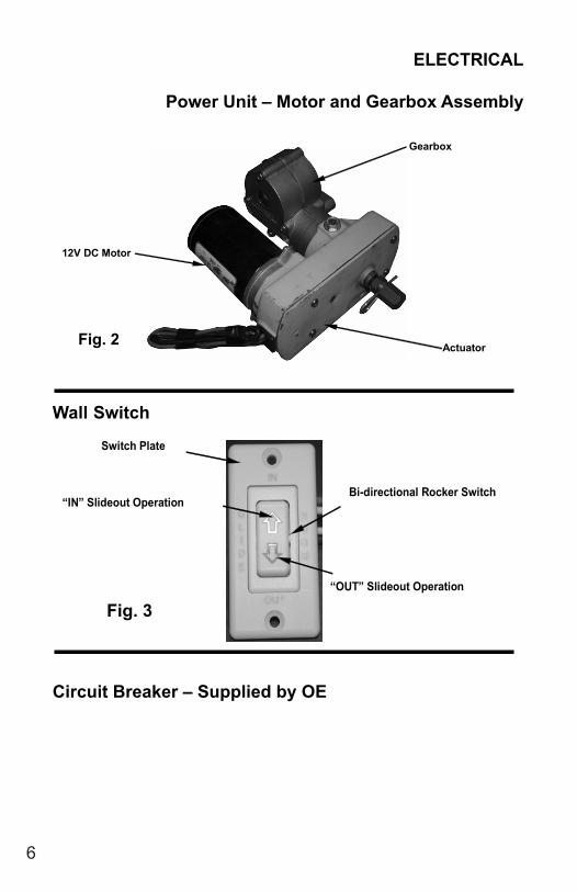
12V DC Motor
Actuator
Gearbox
Fig. 2
Switch Plate
“IN” Slideout Operation
“OUT” Slideout Operation
Bi-directional Rocker Switch
Fig. 3
ELECTRICAL
Power Unit – Motor and Gearbox Assembly
Wall Switch
Circuit Breaker – Supplied by OE
6

OPERATING SYSTEM
WARNINGFAILURE TO ACT IN ACCORDANCE WITH THE FOLLOWING MAYRESULT IN SERIOUS PERSONAL INJURY OR DEATH.
ALWAYS MAKE SURE THAT THE SLIDEOUT ROOM PATH IS CLEAR OFPEOPLE AND OBJECTS BEFORE AND DURING OPERATION OF THESLIDEOUT ROOM.
ALWAYS KEEP AWAY FROM THE SLIDE RAILS WHEN THE ROOM IS BEINGOPERATED. THE GEAR ASSEMBLY MAY PINCH OR CATCH ON LOOSECLOTHING CAUSING PERSONAL INJURY.
INSTALL TRANSIT BARS (IF SO EQUIPPED) ON THE SLIDEOUT ROOMDURING STORAGE AND TRANSPORTATION.
THE FAMILY OF LIPPERT SOFA SLIDE SYSTEMS IS CONTROLLED BY ASWITCH MOUNTED ON THE COACH WALL, NORMALLY LOCATED CLOSETO THE ENTRY DOOR.
EXTENDING SLIDEOUT ROOM
1. Level the unit.2. Verify the battery is fully charged and hooked-up to the electrical system.3. Remove the transit bars (if so equipped).4. Press and hold the IN/OUT switch (Fig. 4B) in the OUT position until the
room is fully extended and stops moving.5. Release the switch, which will lock the room into position.NOTE: If the slideout switch is held after the room in fully extended, the controlwill sense that the room has stopped and will shut off the motor after a fewseconds.
RETRACTING SLIDEOUT ROOM1. Verify the battery is fully charged and hooked-up to the electrical system.2. Press and hold the IN/OUT switch (Fig. 4C) in the IN position until the room
is fully retracted and stops moving.3. Release the switch, which will lock the room into position. NOTE: If the
slideout switch is held after the room in fully retracted, the control will sensethat the room has stopped and will shut off the motor after a few seconds.
4. Install the transit bars (if so equipped).
7

B
Fig. 5 - Slideout Switch and Switch Plate
C
1. Locate coach’s house battery and disconnect the leads. 2. Access the slideout mechanism. Note: This is an above floor style slideout. The motor and slideout mechanism is located inside the coach.
Fig. 6
MANUAL OPERATION
The ABF-24-711-18:1 is equipped with a backup auxiliary power (BAP) systemthat allows you to extend or retract a room if the rooms do not move when switchis pushed.
Check the troubleshooting guide on pages 10-13 for possible solutions beforeusing the backup auxiliary system.
8
WARNING!Always disconnect battery from system prior to manually operating system. Failureto disconnect battery can cause electricity to backfeed through the motor and causeserious damage to the system as well as void the warranty.

3. Disconnect the motor wire. Note: Only one lead needs to be disconnected. CAUTION – If neither lead is disconnected from battery, actuating the system may push an electrical charge back through the motor and damage the motor or other electrical components.
Fig. 7
4. Using a 5/8 in wrench or socket/ratchet combination, rotate the shaft in the counterclockwise to retract slideout room.
Fig. 8
9
WARNING!The gears can be stripped out if the room is manually retracted/extended to it’sfullest extent and the operator continues to rotate manual override.Any damage due to misuse of the Manual Override feature will disqualify any and allclaims to the Limited Warranty.

ELECTRICAL SYSTEM MAINTENANCE
For optimum performance, slide-out system requires full battery current andvoltage. The battery must be maintained at full capacity. Other than good batterymaintenance, check the terminals and other connections at the battery, thecontrol switch, and the electric motor for corrosion, and loose or damagedterminals. Check motor leads under the motorhome chassis. Since theseconnections are subject to damage from road debris, be sure they are in goodcondition.
Note: The Lippert Sofa Slideout System is designed to operate as a negativeground system. A negative ground system utilizes the chassis frame as a groundand an independent ground wire back to battery is necessary (see page 12 forwiring diagram). It is important that the electrical components have good wire tochassis contact. Over 90% of unit electrical problems are due to bad groundconnections.
Note - Once the room has reached its fully extended/retracted position, apply pressure to the wrench to firmly set the room. The worm gear in the gear box will prevent the room from drifting in or out.
5. Using a 5/8 in wrench or socket/ratchet combination, rotate the shaft in the clockwise to extend slideout room.
Fig. 9
10

MECHANICAL MAINTENANCE
Although the system is designed to be almost maintenance free, inspect theslideout for any visible signs of external damage after and before movement ofthe room. Remember to inspect inside the coach as well as the slideout systemoutside the coach.
Note: For long-term storage: It is recommended that the room be closed(retracted).
• When the room is out, visually inspect the Slide Floor and Drive BoxAssemblies. Refer to Fig. 1 for location of rail assemblies. Check forexcess build-up of dirt or other foreign material; remove any debris that maybe present.
• If the system squeaks or makes any noises it is permissible to apply acoat of lightweight oil to the drive shaft and roller areas but remove anyexcess oil so dirt and debris do not build-up. DO NOT use grease.
WARNINGDO NOT WORK ON YOUR SLIDEOUT SYSTEM UNLESS THE BATTERY IS
DISCONNECTED.FAILURE TO ACT IN ACCORDANCE WITH THE FOLLOWING MAY RESULT
IN SERIOUS PERSONAL INJURY OR DEATH.
11

SERVICE
TROUBLESHOOTING
The Lippert Sofa Slideout System is only one of four inter-related slideout soomsystem components. These four components are as follows: chassis, slideoutroom coach and Lippert Sofa Slideout System. Each one needs to functioncorrectly with the others or misalignment problems will occur.
Every coach has it’s own personality and what may work to fix one coach maynot work on another even if the symptoms appear to be the same.
When something restricts room travel, system performances will beunpredictable. It is very important that slide rails, inner and outer, be free ofcontamination and allowed to travel freely the full distance or “STROKE.” Ice ormud build-up during travel is an example of some types of contamination thatmay occur.
When beginning to troubleshoot the system, make sure the battery is fullycharged, there is no visible signs of external damage to the actuator, motor orrails and that the motor is wired properly and all connections are secure.
You can adjust room extension by modifying the position of the rack gear on theslide floor rail to the spur gear on the gear assembly.
During troubleshooting, remember, by changing, altering or adjusting one thing, itmay affect something else. Be sure any changes do not create a new problem.
Additional information on the Lippert Sofa Slideout System by calling 866-524-7821 and asking for technical assistance.
IF YOU HAVE ANY PROBLEMS OR QUESTIONS CONSULT YOUR LOCALAUTHORIZED DEALER OR CALL LIPPERT AT:
(866) 524-7821.
12

TROUBLESHOOTING CHART
The folowing troubleshooting chart outlines some common problems, their causes and possiblecorrective actions. When reference is made to a “Power Unit,” the term includes the motor andthe actuator as a complete unit. All Power Units are shipped from the factory with a serial numberand date code, which should be given to the service technician when asking for assistance.
Notes:If the slideout room will not retract there is a manual override that is located on the opposite sideof the slideout room. A crank handle is provided with your unit. Once you have the room in theclosed position take you unit to the closest dealer. See pages 9-11 for Manual OverrideInstructions.
ROOM DOESN’T MOVE WHEN SWITCH IS PRESSED
PROBABLE CAUSE CORRECTIVE ACTIONRestriction or obstruction inside or outside of unit Check for and clear obstruction
Low battery voltage, blown fuse, defective wiring Check battery voltage and charge if needed
Find and check fuse, replace if blown. Check battery terminals and wiring. Look for loose disconnected or corroded connectors.
Excessive room drag Check that transit bars are removed
POWER UNIT RUNS, ROOM DOES NOT MOVE
Motor turns, room does not move Gear key is broken or lost, replace gear drive assembly
Broken gear on drive shaft Replace gear drive assembly
Broken gear in gearbox Replace motor/gearbox assembly
Bad motor or gearbox Replace motor/gearbox assembly
POWER UNIT RUNS, ROOM MOVES SLOWLY
Low battery, poor ground, extremely low Charge battery, check ground wiretemperature
Room in bind Adjust to proper room setting
Incorrect height adjustment Check for proper room height
ROOM STARTS TO MOVE AND STOPS
Low battery voltage, blown fuse, defective wiring Check battery voltage and charge if needed
Find and check fuse, replace if blown. Check battery terminals and wiring. Look for loose disconnected or corroded connectors.
Obstruction of room inside or outside Check for and remove any obstruction
Dirts or corrosion build up on mechanism Clean dirt or corrosion and coat LIGHTLY with oil
ROOM CHATTERS DURING OPERATION
Teeth on gear drive broken or worn Replace gear drive assembly
Teeth on inner rail broken or worn Replace inner rail assembly
13

Switch related problems:• If room moves opposite from what the switch plate indicates, reverse the motor wires on the back of the switch (refer to the wiring diagram page 12). Wire size must be 10ga. Min.• If a gear is stripped, the entire gearbox must be replaced.• If the room does not seal fully, refer to page 11.
TROUBLESHOOTING – POWER UNIT
Before attempting to troubleshoot the PowerUnit, make sure an adequate powersource is available. The unit batteries should be fully charged or the unit shouldbe plugged into to A/C service with batteries installed. Do not attempt totroubleshoot the Power Unit without assuring a full 12V DC charge
The following tests require only a DC voltmeter (or DC test light) and a jumperlead.
Step 1 - Attach voltmeter (or test light) leads to the negative and positive switchterminals on back of wall switch (See Fig. 11). Does the meter indicate 12V DC?If YES, see Step 2; if NO see Step 3.
Step 2 - If YES, at the motor, check the incoming leads to 12V DC (if necessary,disconnect leads at wire splices). Does meter indicate 12V DC? If YES, PowerUnit needs to be replaced. The motor is not field serviceable. DO NOTATTEMPT TO REPAIR. If NO, Inspect all wires and connections bewtween thewall switch and the motor. Repair connections as necessary. Recheck as inStep 1.
Step 3 - If NO, Inspect all connections between battery and switch. Inspect 30ACircuit Breaker (See Fig. 11). Recheck as above in Step 1.
Since there are no field serviceable parts in the motor of the Power Unit,electrical troubleshooting and service is limited to replacing only thosecomponents as previously outlined.
Thorough inspection of wiring and connections is the only other electrical servicethat can be performed.
14

B
ATTE
RY
MO
TOR
R
ED
CH
ANG
E O
F P
OLA
RIT
Y R
EV
ER
SES
MO
TOR
GR
EE
N
M
OTO
R
10 G
A W
IRE
MIN
IMU
M
30A
AU
TO R
ESE
T B
RE
AK
ER
LOC
ATE
WIT
HIN
18”
OF
BAT
TER
Y
IN
SWIT
CH
BAT
TER
Y (-
) WH
ITE
BAT
TER
Y (+
) BLA
CK
BAT
TER
Y (-
) W
HIT
E
OU
T
-
+
RE
D
M
OTO
R
BLA
CK B
ATTE
RY
(-)
BAT
TER
Y (+
)
CA
UTI
ON
! H
IGH
VO
LTA
GE
Fig. 11
WIRING DIAGRAM
15

ORDERING PARTS
To assist the customer service when ordering parts, please provide the followinginformation:
1. Your Name
2. Company Name
3. Phone Number
4. Shipping Address
5. Billing Address
6. Purchase Order Number
7. Coach A. Serial # and/or VIN # B. Make C. Model
8. Part Number
9. Description
10. Quantity
Please take your coach to an authorized service center for repairs. Systemsthat have been modified, adjusted, repaired or augmented by a party otherthan an authorized service center may void any warranty claim with LippertComponents, Inc.
16