5th Wheel Hydraulic Slideout Landing Gear-Web WARNING FAILURE TO ACT IN ACCORDANCE WITH THE...
31
OPERATION AND SERVICE MANUAL LIPPERTCOMPONENTS 5TH WHEEL HYDRAULIC SLIDEOUT AND LANDING GEAR (HLG) SYSTEM
-
Upload
truongdieu -
Category
Documents
-
view
224 -
download
1
Transcript of 5th Wheel Hydraulic Slideout Landing Gear-Web WARNING FAILURE TO ACT IN ACCORDANCE WITH THE...
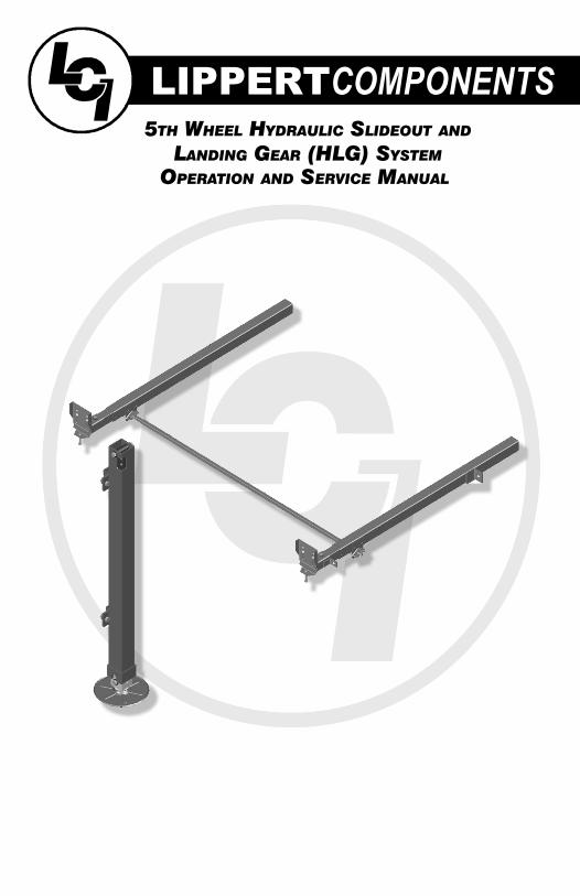
OPERATION AND SERVICE MANUAL
LIPPERTCOMPONENTS5TH WHEEL HYDRAULIC SLIDEOUT AND
LANDING GEAR (HLG) SYSTEM
334456
8899
1012
1313
1414151819202426283032
TABLE OF CONTENTS
SYSTEM……………………………………………........….…..Warning…………………………………........……....Prior to Operation…………………….......………Description………………………………........……..Preventative Maintenance……….......………..System Maintenance....................................
OPERATION-SLIDEOUTS………….……........……………Warning.........................................................Extending Slideout Room….............………….Retracting Slideout Room…….............……...Slideout Diagram..........................................Auxiliary Operation…………….......................
OPERATION-HYDRAULIC LANDING GEAR...............Warning.........................................................
SERVICE…………………………..………………........………Filling Procedures........................................Adjustment Instructions……….......…………..Syncronizing System...................................Replacing Actuator......................................Troubleshooting…………………….........………Plumbing Diagram……….……….….......………Manifold Diagram………..……….….......………Wiring Harness Diagram..………………………Switch Diagram...........................................Ordering Parts.............................................
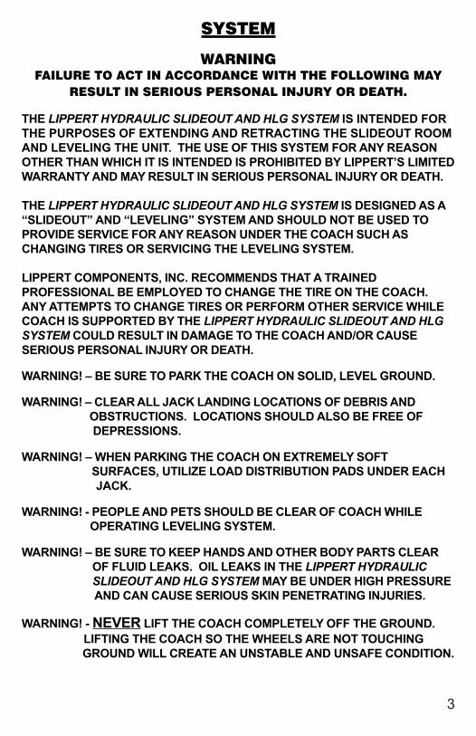
SYSTEM
WARNINGFAILURE TO ACT IN ACCORDANCE WITH THE FOLLOWING MAY
RESULT IN SERIOUS PERSONAL INJURY OR DEATH.
THE LIPPERT HYDRAULIC SLIDEOUT AND HLG SYSTEM IS INTENDED FORTHE PURPOSES OF EXTENDING AND RETRACTING THE SLIDEOUT ROOMAND LEVELING THE UNIT. THE USE OF THIS SYSTEM FOR ANY REASONOTHER THAN WHICH IT IS INTENDED IS PROHIBITED BY LIPPERT’S LIMITEDWARRANTY AND MAY RESULT IN SERIOUS PERSONAL INJURY OR DEATH.
THE LIPPERT HYDRAULIC SLIDEOUT AND HLG SYSTEM IS DESIGNED AS A“SLIDEOUT” AND “LEVELING” SYSTEM AND SHOULD NOT BE USED TOPROVIDE SERVICE FOR ANY REASON UNDER THE COACH SUCH ASCHANGING TIRES OR SERVICING THE LEVELING SYSTEM.
LIPPERT COMPONENTS, INC. RECOMMENDS THAT A TRAINEDPROFESSIONAL BE EMPLOYED TO CHANGE THE TIRE ON THE COACH.ANY ATTEMPTS TO CHANGE TIRES OR PERFORM OTHER SERVICE WHILECOACH IS SUPPORTED BY THE LIPPERT HYDRAULIC SLIDEOUT AND HLGSYSTEM COULD RESULT IN DAMAGE TO THE COACH AND/OR CAUSESERIOUS PERSONAL INJURY OR DEATH.
WARNING! – BE SURE TO PARK THE COACH ON SOLID, LEVEL GROUND.
WARNING! – CLEAR ALL JACK LANDING LOCATIONS OF DEBRIS AND OBSTRUCTIONS. LOCATIONS SHOULD ALSO BE FREE OF DEPRESSIONS.
WARNING! – WHEN PARKING THE COACH ON EXTREMELY SOFT SURFACES, UTILIZE LOAD DISTRIBUTION PADS UNDER EACH JACK.
WARNING! - PEOPLE AND PETS SHOULD BE CLEAR OF COACH WHILE OPERATING LEVELING SYSTEM.
WARNING! – BE SURE TO KEEP HANDS AND OTHER BODY PARTS CLEAR OF FLUID LEAKS. OIL LEAKS IN THE LIPPERT HYDRAULIC
SLIDEOUT AND HLG SYSTEM MAY BE UNDER HIGH PRESSURE AND CAN CAUSE SERIOUS SKIN PENETRATING INJURIES.
WARNING! - NEVER LIFT THE COACH COMPLETELY OFF THE GROUND. LIFTING THE COACH SO THE WHEELS ARE NOT TOUCHING GROUND WILL CREATE AN UNSTABLE AND UNSAFE CONDITION.
3
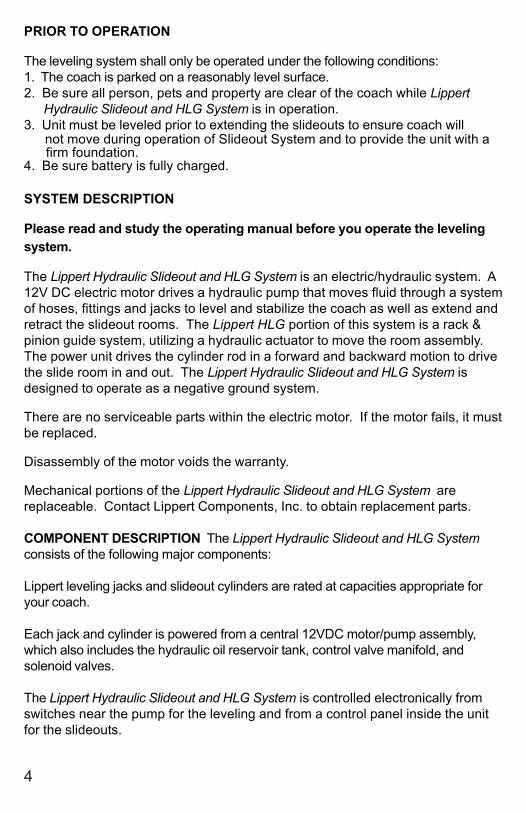
PRIOR TO OPERATION
The leveling system shall only be operated under the following conditions:1. The coach is parked on a reasonably level surface.2. Be sure all person, pets and property are clear of the coach while Lippert Hydraulic Slideout and HLG System is in operation.3. Unit must be leveled prior to extending the slideouts to ensure coach will not move during operation of Slideout System and to provide the unit with a firm foundation.4. Be sure battery is fully charged.
SYSTEM DESCRIPTION
Please read and study the operating manual before you operate the levelingsystem.
The Lippert Hydraulic Slideout and HLG System is an electric/hydraulic system. A12V DC electric motor drives a hydraulic pump that moves fluid through a systemof hoses, fittings and jacks to level and stabilize the coach as well as extend andretract the slideout rooms. The Lippert HLG portion of this system is a rack &pinion guide system, utilizing a hydraulic actuator to move the room assembly.The power unit drives the cylinder rod in a forward and backward motion to drivethe slide room in and out. The Lippert Hydraulic Slideout and HLG System isdesigned to operate as a negative ground system.
There are no serviceable parts within the electric motor. If the motor fails, it mustbe replaced.
Disassembly of the motor voids the warranty.
Mechanical portions of the Lippert Hydraulic Slideout and HLG System arereplaceable. Contact Lippert Components, Inc. to obtain replacement parts.
COMPONENT DESCRIPTION The Lippert Hydraulic Slideout and HLG Systemconsists of the following major components:
Lippert leveling jacks and slideout cylinders are rated at capacities appropriate foryour coach.
Each jack and cylinder is powered from a central 12VDC motor/pump assembly,which also includes the hydraulic oil reservoir tank, control valve manifold, andsolenoid valves.
The Lippert Hydraulic Slideout and HLG System is controlled electronically fromswitches near the pump for the leveling and from a control panel inside the unitfor the slideouts.
4

PREVENTATIVE MAINTENANCE PROCEDURES
The Lippert Hydraulic Slideout and HLG System has been designed to require verylittle maintenance. To ensure the long life of your system, read and follow thesefew simple procedures.
1. Change fluid every 36 months (in reservoir ONLY!).a) Check fluid only when jacks and slideouts are fully retracted.b) Always fill the reservoir with the jacks and slideouts are in the fully retracted
position. Filling reservoir when jacks and slideouts are extended will causereservoir to overflow into its compartment when jacks and slideouts areretracted.
c) When checking fluid level, fluid should be within 1/2” of fill spout lip.
2. Check the fluid level every month.
3. Inspect and clean all Pump Unit electrical connections every 12 months.
4. Remove dirt and road debris from jacks and slideout arms and cylinders as needed.
WARNING!YOUR COACH SHOULD BE SUPPORTED AT BOTH FRONT AND REAR
AXLES WITH JACK STANDS BEFORE WORKING UNDERNEATH.FAILURE TO DO SO MAY RESULT IN PERSONAL INJURY OR DEATH.
5. If jacks are down and/or slideouts are extended for lengthy periods, it is recommended to spray exposed jack and cylinder rods with a silicone lubricant every seven days for protection. If your coach is located in a salty environment, it is recommended to spray the rods every 2 to 3 days.
IF YOU HAVE ANY PROBLEMS OR QUESTIONS CONSULT YOUR LOCALAUTHORIZED DEALER OR CALL LIPPERT AT:
(866) 524-7821.
WARNING!DO NOT WORK ON YOUR SLIDEOUT SYSTEM UNLESS THE BATTERY IS
DISCONNECTED. FAILURE TO ACT IN ACCORDANCE WITH THEFOLLOWING MAY RESULT IN SERIOUS PERSONAL INJURY OR DEATH.
5
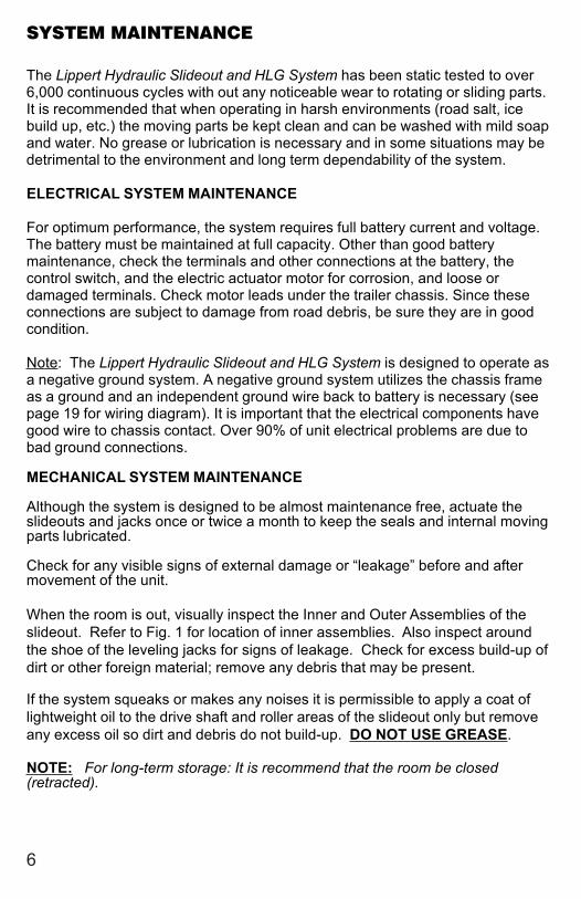
SYSTEM MAINTENANCE
The Lippert Hydraulic Slideout and HLG System has been static tested to over6,000 continuous cycles with out any noticeable wear to rotating or sliding parts.It is recommended that when operating in harsh environments (road salt, icebuild up, etc.) the moving parts be kept clean and can be washed with mild soapand water. No grease or lubrication is necessary and in some situations may bedetrimental to the environment and long term dependability of the system.
ELECTRICAL SYSTEM MAINTENANCE
For optimum performance, the system requires full battery current and voltage.The battery must be maintained at full capacity. Other than good batterymaintenance, check the terminals and other connections at the battery, thecontrol switch, and the electric actuator motor for corrosion, and loose ordamaged terminals. Check motor leads under the trailer chassis. Since theseconnections are subject to damage from road debris, be sure they are in goodcondition.
Note: The Lippert Hydraulic Slideout and HLG System is designed to operate asa negative ground system. A negative ground system utilizes the chassis frameas a ground and an independent ground wire back to battery is necessary (seepage 19 for wiring diagram). It is important that the electrical components havegood wire to chassis contact. Over 90% of unit electrical problems are due tobad ground connections.
MECHANICAL SYSTEM MAINTENANCE
Although the system is designed to be almost maintenance free, actuate theslideouts and jacks once or twice a month to keep the seals and internal movingparts lubricated.
Check for any visible signs of external damage or “leakage” before and aftermovement of the unit.
When the room is out, visually inspect the Inner and Outer Assemblies of theslideout. Refer to Fig. 1 for location of inner assemblies. Also inspect aroundthe shoe of the leveling jacks for signs of leakage. Check for excess build-up ofdirt or other foreign material; remove any debris that may be present.
If the system squeaks or makes any noises it is permissible to apply a coat oflightweight oil to the drive shaft and roller areas of the slideout only but removeany excess oil so dirt and debris do not build-up. DO NOT USE GREASE.
NOTE: For long-term storage: It is recommend that the room be closed(retracted).
6
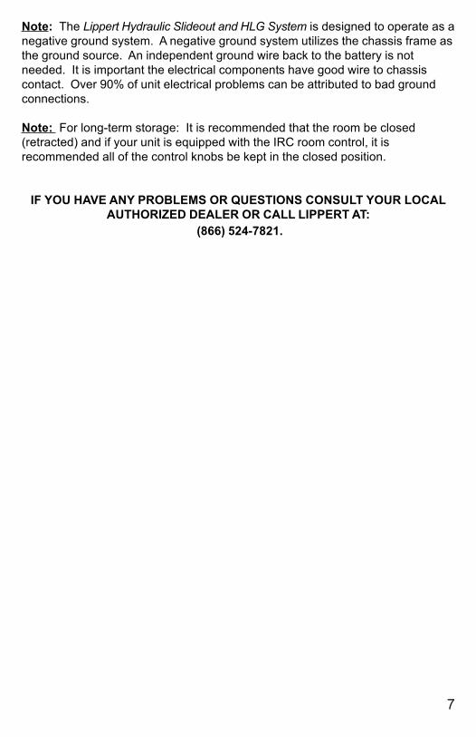
Note: The Lippert Hydraulic Slideout and HLG System is designed to operate as anegative ground system. A negative ground system utilizes the chassis frame asthe ground source. An independent ground wire back to the battery is notneeded. It is important the electrical components have good wire to chassiscontact. Over 90% of unit electrical problems can be attributed to bad groundconnections.
Note: For long-term storage: It is recommended that the room be closed(retracted) and if your unit is equipped with the IRC room control, it isrecommended all of the control knobs be kept in the closed position.
IF YOU HAVE ANY PROBLEMS OR QUESTIONS CONSULT YOUR LOCALAUTHORIZED DEALER OR CALL LIPPERT AT:
(866) 524-7821.
7

OPERATION-HYDRAULIC SLIDEOUT
WARNINGFAILURE TO ACT IN ACCORDANCE WITH THE FOLLOWING MAYRESULT IN SERIOUS PERSONAL INJURY OR DEATH.
ALWAYS MAKE SURE THAT THE SLIDEOUT ROOM PATH IS CLEAR OFPEOPLE AND OBJECTS BEFORE AND DURING OPERATION OF THESLIDEOUT ROOM.
ALWAYS KEEP AWAY FROM THE SLIDE RAILS WHEN THE ROOM IS BEINGOPERATED. THE GEAR ASSEMBLY MAY PINCH OR CATCH ON LOOSECLOTHING CAUSING PERSONAL INJURY.
INSTALL TRANSIT BARS (IF SO EQUIPPED) ON THE SLIDEOUT ROOMDURING STORAGE AND TRANSPORTATION.
Fig. 1
SLIDEOUT CONTROL PANEL
1a
1b
8
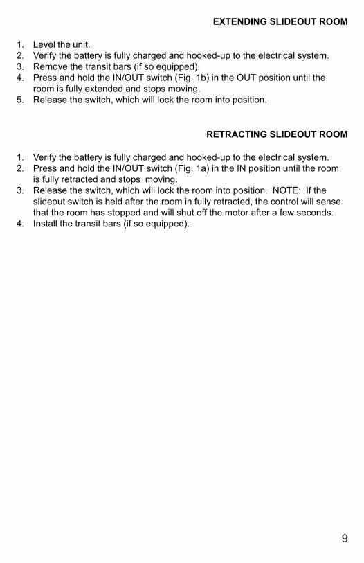
EXTENDING SLIDEOUT ROOM
1. Level the unit.2. Verify the battery is fully charged and hooked-up to the electrical system.3. Remove the transit bars (if so equipped).4. Press and hold the IN/OUT switch (Fig. 1b) in the OUT position until the
room is fully extended and stops moving.5. Release the switch, which will lock the room into position.
RETRACTING SLIDEOUT ROOM
1. Verify the battery is fully charged and hooked-up to the electrical system.2. Press and hold the IN/OUT switch (Fig. 1a) in the IN position until the room
is fully retracted and stops moving.3. Release the switch, which will lock the room into position. NOTE: If the
slideout switch is held after the room in fully retracted, the control will sensethat the room has stopped and will shut off the motor after a few seconds.
4. Install the transit bars (if so equipped).
9
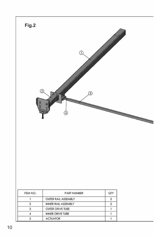
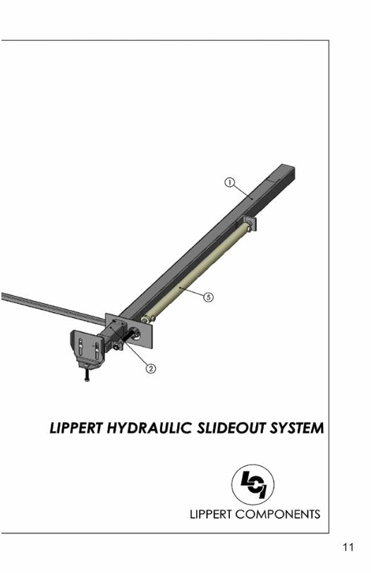
Fig.2
10
11
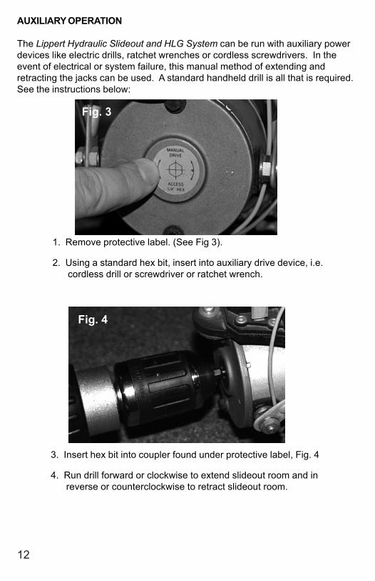
AUXILIARY OPERATION
The Lippert Hydraulic Slideout and HLG System can be run with auxiliary powerdevices like electric drills, ratchet wrenches or cordless screwdrivers. In theevent of electrical or system failure, this manual method of extending andretracting the jacks can be used. A standard handheld drill is all that is required.See the instructions below:
1. Remove protective label. (See Fig 3).
2. Using a standard hex bit, insert into auxiliary drive device, i.e. cordless drill or screwdriver or ratchet wrench.
3. Insert hex bit into coupler found under protective label, Fig. 4
4. Run drill forward or clockwise to extend slideout room and in reverse or counterclockwise to retract slideout room.
Fig. 3
Fig. 4
12
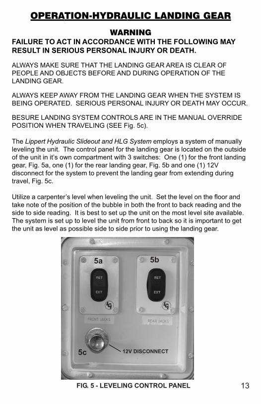
OPERATION-HYDRAULIC LANDING GEAR
WARNINGFAILURE TO ACT IN ACCORDANCE WITH THE FOLLOWING MAYRESULT IN SERIOUS PERSONAL INJURY OR DEATH.
ALWAYS MAKE SURE THAT THE LANDING GEAR AREA IS CLEAR OFPEOPLE AND OBJECTS BEFORE AND DURING OPERATION OF THELANDING GEAR.
ALWAYS KEEP AWAY FROM THE LANDING GEAR WHEN THE SYSTEM ISBEING OPERATED. SERIOUS PERSONAL INJURY OR DEATH MAY OCCUR.
BESURE LANDING SYSTEM CONTROLS ARE IN THE MANUAL OVERRIDEPOSITION WHEN TRAVELING (SEE Fig. 5c).
The Lippert Hydraulic Slideout and HLG System employs a system of manuallyleveling the unit. The control panel for the landing gear is located on the outsideof the unit in it’s own compartment with 3 switches: One (1) for the front landinggear, Fig. 5a, one (1) for the rear landing gear, Fig. 5b and one (1) 12Vdisconnect for the system to prevent the landing gear from extending duringtravel, Fig. 5c.
Utilize a carpenter’s level when leveling the unit. Set the level on the floor andtake note of the position of the bubble in both the front to back reading and theside to side reading. It is best to set up the unit on the most level site available.The system is set up to level the unit from front to back so it is important to getthe unit as level as possible side to side prior to using the landing gear.
FIG. 5 - LEVELING CONTROL PANEL
12V DISCONNECT
5a 5b
5c
13
SERVICE
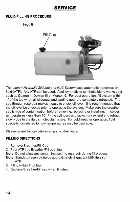
FLUID FILLING PROCEDURE
The Lippert Hydraulic Slideout and HLG System uses automatic transmissionfluid (ATF). Any ATF can be used. A full synthetic or synthetic blend works bestsuch as Dexron II, Dexron III or Mercon 5. For best operation, fill system within1” of the top when all slideouts and landing gear are completely retracted. Thesee through reservoir makes it easy to check oil level. It is recommended thatthe oil level be checked prior to operating the system. Make sure the breathercap is free of contamination before removing, replacing or installing. In coldertemperatures (less than 10° F) the cylinders and jacks may extend and retractslowly due to the fluid’s molecular nature. For cold weather operation, fluidspecially formulated for low temperatures may be desirable.
Please consult factory before using any other fluids.
FILLING DIRECTIONS
1. Remove Breather/Fill Cap2. Pour ATF into Breather/Fill opening.Note: Do not allow any contamination into reservoir during fill process.Note: Standard reservoir holds approximately 2 quarts (1.89 liters) of ATF.3. Fill to within 1” of top.4. Replace Breather/Fill cap when finished.
14
Fig. 6
Fill Cap

15
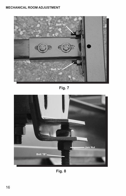
MECHANICAL ROOM ADJUSTMENT
Vertical & Horizontal Room Adjustment
NOTE: All slideout room adjustments must be performed by certified service technicians. Adjustments made by non-certified persons may void any and all warranty claims.
Horizontal adjustment - See pg. 16, Fig. 7
1. Loosen 2 carriage bolts “A” on each bracket located at the end of each guide tube.2. Room is ready to be positioned horizontally by pushing on the outside, sidewall or by using a prying devise inserted into the opening between the room and coach.
Note: Use caution when using prying devise so seals do not becomedamaged.
Vertical adjustment - See pg. 16, Fig. 8
1. Loosen 2 carriage bolts “A” on each bracket located at the end of each guide tube2. Loosen jam nut3. For vertical adjustment turn vertical adjustment bolt “B” up or down to locate room height.
Once room is located, tighten “A” and Jam Nut bolts.
MECHANICAL ROOM ADJUSTMENT
Fig. 7
Bolt “B”
Jam Nut
Bolt “A”
Bolt “A”
Fig. 8
16
17
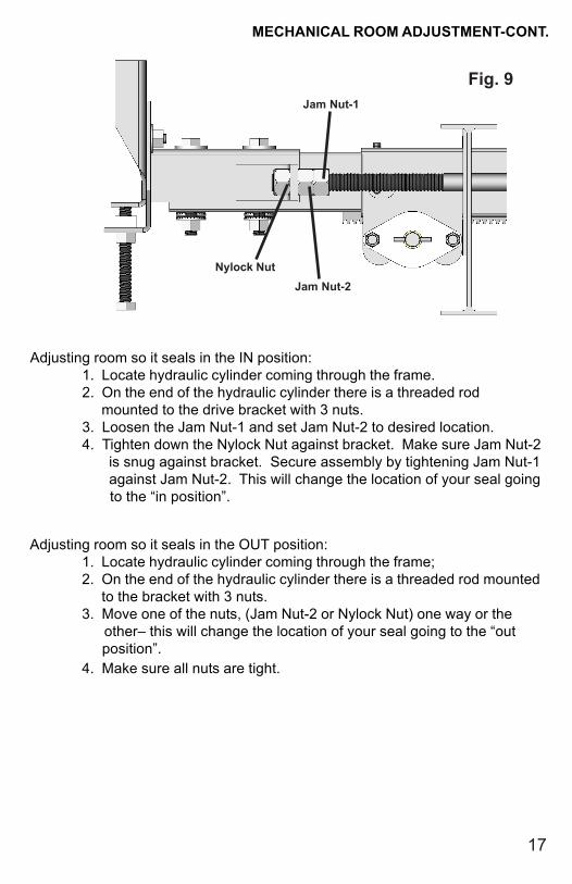
MECHANICAL ROOM ADJUSTMENT-CONT.
Jam Nut-1
Jam Nut-2
Fig. 9
Nylock Nut
Adjusting room so it seals in the IN position:1. Locate hydraulic cylinder coming through the frame.2. On the end of the hydraulic cylinder there is a threaded rod mounted to the drive bracket with 3 nuts.3. Loosen the Jam Nut-1 and set Jam Nut-2 to desired location.4. Tighten down the Nylock Nut against bracket. Make sure Jam Nut-2
is snug against bracket. Secure assembly by tightening Jam Nut-1 against Jam Nut-2. This will change the location of your seal going to the “in position”.
Adjusting room so it seals in the OUT position:1. Locate hydraulic cylinder coming through the frame;2. On the end of the hydraulic cylinder there is a threaded rod mounted to the bracket with 3 nuts.3. Move one of the nuts, (Jam Nut-2 or Nylock Nut) one way or the
other– this will change the location of your seal going to the “out position”.
4. Make sure all nuts are tight.
18
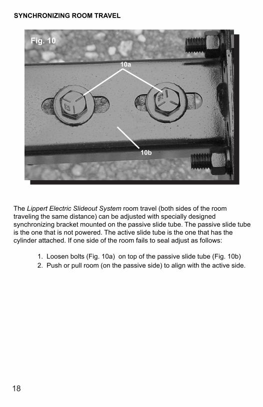
SYNCHRONIZING ROOM TRAVEL
The Lippert Electric Slideout System room travel (both sides of the roomtraveling the same distance) can be adjusted with specially designedsynchronizing bracket mounted on the passive slide tube. The passive slide tubeis the one that is not powered. The active slide tube is the one that has thecylinder attached. If one side of the room fails to seal adjust as follows:
1. Loosen bolts (Fig. 10a) on top of the passive slide tube (Fig. 10b)2. Push or pull room (on the passive side) to align with the active side.
Fig. 10
10a
10b
19
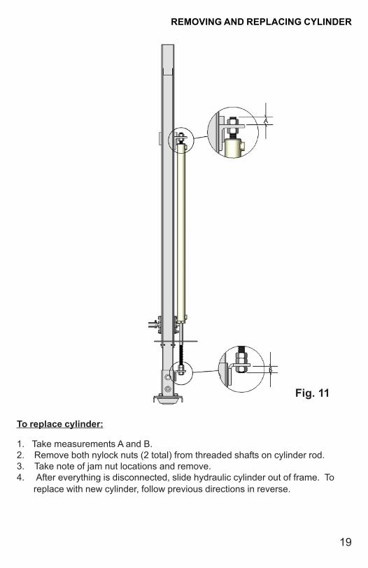
To replace cylinder:
1. Take measurements A and B.2. Remove both nylock nuts (2 total) from threaded shafts on cylinder rod.3. Take note of jam nut locations and remove.4. After everything is disconnected, slide hydraulic cylinder out of frame. To replace with new cylinder, follow previous directions in reverse.
REMOVING AND REPLACING CYLINDER
Fig. 11

20
TROUBLESHOOTING
Hydraulic Landing Gear (HLG).................................................21
Hydraulic Slideout System.......................................................21
Troubleshooting Chart - Slideouts..........................................22
Troubleshooting Chart - HLG...................................................22
Checking for Bad Cylinder.......................................................23
Power Unit.................................................................................23
21
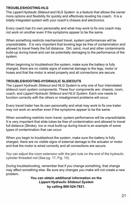
TROUBLESHOOTING-HLGThe Lippert Hydraulic Slideout and HLG System is a feature that allows the ownermore options and flexibility for quickly and effectively leveling his coach. It is atotally integrated system with your coach’s chassis and electronics.
Every coach has it’s own personality and what may work to fix one coach maynot work on another even if the symptoms appear to be the same.
When something restricts mechanized travel, system performances will beunpredictable. It is very important that leveling legs be free of contamination andallowed to travel freely the full distance. Dirt, sand, mud and other contaminantsbuild-up during travel and can be potentially damaging to the performance of thesystem.
When beginning to troubleshoot the system, make sure the battery is fullycharged, there are no visible signs of external damage to the legs, motor orhoses and that the motor is wired properly and all connections are secure.
TROUBLESHOOTING-HYDRAULIC SLIDEOUTSThe Lippert Hydraulic Slideout and HLG System is only one of four interrelatedslideout room system components. These four components are: chassis, room,coach, and Lippert Hydraulic Slideout and HLG System. Each one needs tofunction correctly with the others or misalignment problems will occur.
Every travel trailer has its own personality and what may work to fix one trailermay not work on another even if the symptoms appear to be the same.
When something restricts room travel, system performance will be unpredictable.It is very important that slide tubes be free of contamination and allowed to travelfull distance (Stroke). Ice or mud build-up during travel is an example of sometypes of contamination that can occur.
When you begin to troubleshoot the system, make sure the battery is fullycharged, there are no visible signs of external damage to the actuator or motorand that the motor is wired correctly and all connections are secure.
You can adjust the room extension with the jam nuts on the end of the hydrauliccylinder threaded rod (See pg. 17, Fig. 10).
During troubleshooting, remember that if you change something, that changemay affect something else. Be sure any changes you make will not create a newproblem.
You can obtain additional information on theLippert Hydraulic Slideout System
by calling 866-524-7821.

22
TROUBLESHOOTING CHART - SLIDEOUT
The following troubleshooting chart outlines some common problems, their causes and possiblecorrective actions. When reference is made to a “Power Unit,” the term includes the motor andthe actuator as a complete unit. All Power Units are shipped from the factory with a serial numberand date code, which should be given to the service technician when asking for assistance.
ROOM DOESN’T MOVE WHEN SWITCH IS PRESSEDPROBABLE CAUSE CORRECTIVE ACTIONRestrictions both inside and outside of unit Check for and clear restriction
Low battery voltage, blown fuse, defective wiring Check battery. Charge battery or add auxiliarypower source. Check battery terminals, and all
other wiring. Look for loose or corrodedconnections
Power Unit not functioning See “Power Unit Troubleshooting” page 22
POWER UNIT RUNS, ROOM DOES NOT MOVERestrictions both inside and outside of unit Check for and clear restriction
POWER UNIT RUNS, ROOM MOVES SLOWLYLow battery, poor ground, extremely low Charge battery, and check ground wireoutdoor temperature.
Leaking cylinder See “Checking for Bad Cylinder” page 22
ROOM DRIFTS IN BOTH IN & OUT POSITIONSCheck for leaks in the hydraulic system Tighten fittings
Air in system After checking all connections, cycle pumpseveral times in and out
IN THE CLOSED POSITION, ROOM DRIFTS OUTLeaking cylinder seal See “Checking for Bad Cylinder” page 22
Fluid bypassing cylinder piston See “Checking for Bad Cylinder” page 22
Hose from pump is leaking Tighten fitting or replace hose
Air in system After checking all connections, cycle pumpseveral times in and out
Loose mounting bolts Tighten mounting bolts
IN THE OPEN POSITION, ROOM DRIFTS INHose from pump is leaking Tighten fitting or replace hose
Leaking cylinder seal See “Checking for Bad Cylinder” page 22
Fluid bypassing cylinder piston See “Checking for Bad Cylinder” page 22
TROUBLESHOOTING CHART - HLG JACKS WILL NOT EXTEND TO GROUND, PUMP IS RUNNING
PROBABLE CAUSE CORRECTIVE ACTION
Little or no fluid in reservoir Fill reservoir with DEXRON III ATF, See pg. 14Leg valve is inoperative Clean, repair or replaceElectronic signal is lost between switch Trace wires for voltage drop or loss of signal and leg valves Repair or replace necessary wires or replace
switch. ANY ONE OR TWO JACKS WILL NOT RETRACT
PROBABLE CAUSE CORRECTIVE ACTION
Hose damaged or unconnected Replace with new hose or reconnect hoseReturn valve inoperative Replace inoperative return valveElectronic signal is lost between switch Attempt to retract jacks in MANUAL mode. and solenoid If successful, replace control pad; if not, test for voltage drop between switch and leg valve Repair bad wiring or replace defective board or valve.
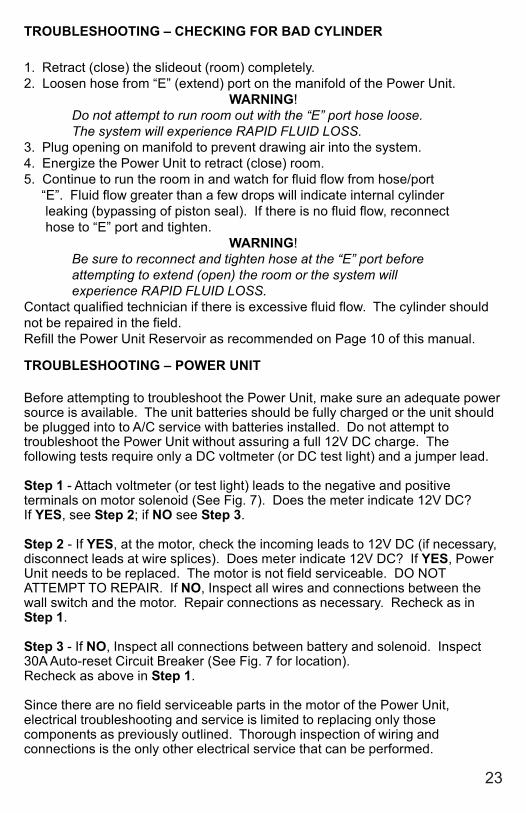
TROUBLESHOOTING – CHECKING FOR BAD CYLINDER
1. Retract (close) the slideout (room) completely.2. Loosen hose from “E” (extend) port on the manifold of the Power Unit.
WARNING!Do not attempt to run room out with the “E” port hose loose.The system will experience RAPID FLUID LOSS.
3. Plug opening on manifold to prevent drawing air into the system.4. Energize the Power Unit to retract (close) room.5. Continue to run the room in and watch for fluid flow from hose/port “E”. Fluid flow greater than a few drops will indicate internal cylinder leaking (bypassing of piston seal). If there is no fluid flow, reconnect hose to “E” port and tighten.
WARNING!Be sure to reconnect and tighten hose at the “E” port beforeattempting to extend (open) the room or the system willexperience RAPID FLUID LOSS.
Contact qualified technician if there is excessive fluid flow. The cylinder shouldnot be repaired in the field.Refill the Power Unit Reservoir as recommended on Page 10 of this manual.
TROUBLESHOOTING – POWER UNIT
Before attempting to troubleshoot the Power Unit, make sure an adequate powersource is available. The unit batteries should be fully charged or the unit shouldbe plugged into to A/C service with batteries installed. Do not attempt totroubleshoot the Power Unit without assuring a full 12V DC charge. Thefollowing tests require only a DC voltmeter (or DC test light) and a jumper lead.
Step 1 - Attach voltmeter (or test light) leads to the negative and positiveterminals on motor solenoid (See Fig. 7). Does the meter indicate 12V DC?If YES, see Step 2; if NO see Step 3.
Step 2 - If YES, at the motor, check the incoming leads to 12V DC (if necessary,disconnect leads at wire splices). Does meter indicate 12V DC? If YES, PowerUnit needs to be replaced. The motor is not field serviceable. DO NOTATTEMPT TO REPAIR. If NO, Inspect all wires and connections between thewall switch and the motor. Repair connections as necessary. Recheck as inStep 1.
Step 3 - If NO, Inspect all connections between battery and solenoid. Inspect30A Auto-reset Circuit Breaker (See Fig. 7 for location).Recheck as above in Step 1.
Since there are no field serviceable parts in the motor of the Power Unit,electrical troubleshooting and service is limited to replacing only thosecomponents as previously outlined. Thorough inspection of wiring andconnections is the only other electrical service that can be performed.
23
24
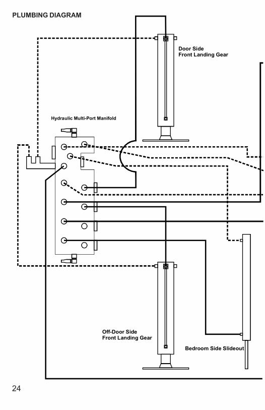
PLUMBING DIAGRAM
Door SideFront Landing Gear
Off-Door SideFront Landing Gear
Bedroom Side Slideout
Hydraulic Multi-Port Manifold
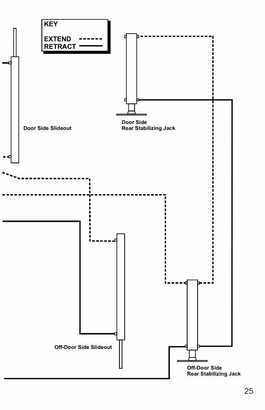
25
Door SideRear Stabilizing Jack
Off-Door SideRear Stabilizing Jack
Door Side Slideout
Off-Door Side Slideout
KEY
EXTENDRETRACT

26
YELLOW
GREEN
PURP
LEBL
ACK/
WHI
TE
RED
PURPLE/WHITE& BLACK
PURPLE& BLACK TAN
& BLACK
ORANGE& BLACK
BLUE& BLACK
BLACK/WHITE
REDGREY
GREYRED
PURPLE
TAN
ORANGE
1
6
5
4
3
2
1
12
34
1
34
2
3
456
CONNECTOR KEY
- DEUTSCH STYLE
- FEMALE FAST-ON
- SINGLE WIRE EYE
27
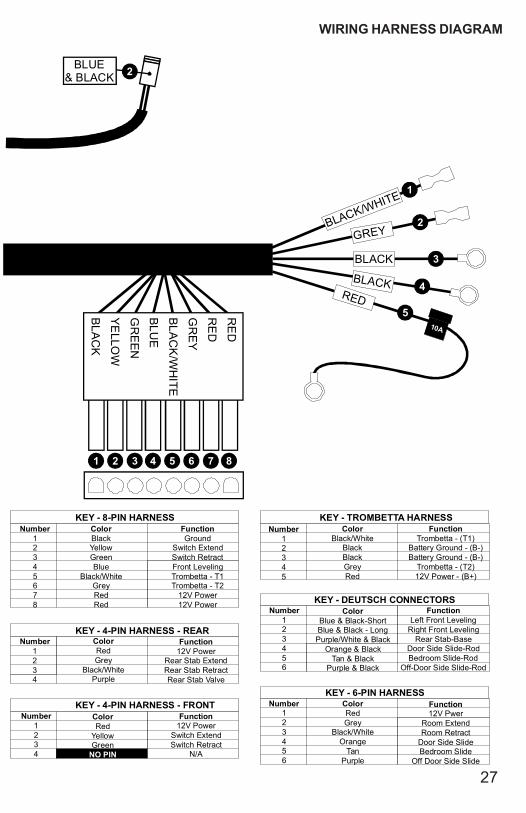
WIRING HARNESS DIAGRAM
RE
D
RE
D
GR
EY
BLA
CK
/WH
ITE
BLU
E
GR
EE
N
YE
LLOW
BLA
CK
BLACK
BLACK/WHITE
GREY
RED
10A
BLUE& BLACK
3
2
1
BLACK
4
5
1 2 3 4 5 6 7 8
2
Number12345678
ColorBlack YellowGreenBlue
Black/WhiteGreyRedRed
FunctionGround
Switch ExtendSwitch RetractFront LevelingTrombetta - T1Trombetta - T2
12V Power12V Power
KEY - 4-PIN HARNESS - REAR
KEY - 8-PIN HARNESS
KEY - 4-PIN HARNESS - FRONT
KEY - TROMBETTA HARNESS
KEY - DEUTSCH CONNECTORS
KEY - 6-PIN HARNESS
Number1234
ColorRed Grey
Black/WhitePurple
Number1234
ColorRed
YellowGreen
NO PIN
Number12345
ColorBlack/White
BlackBlackGreyRed
Number123456
ColorBlue & Black-ShortBlue & Black - Long
Purple/White & BlackOrange & Black
Purple & BlackTan & Black
Number123456
ColorRed Grey
Black/WhiteOrange
TanPurple
Function12V Power
Rear Stab ExtendRear Stab RetractRear Stab Valve
FunctionTrombetta - (T1)
Battery Ground - (B-)Battery Ground - (B-)
Trombetta - (T2)12V Power - (B+)
FunctionLeft Front Leveling
Right Front LevelingRear Stab-Base
Door Side Slide-Rod
Off-Door Side Slide-RodBedroom Slide-Rod
Function12V Pwer
Room ExtendRoom Retract
Door Side SlideBedroom Slide
Off Door Side Slide
Function12V Power
Switch ExtendSwitch Retract
N/A

28
- +
M1T1
B- B+T2
M2
12345678
8-PIN HARNESS
BATTERY
RESERVOIRMOTORM
AN
IFO
LD
TROMBETTA
DELAY TIMER
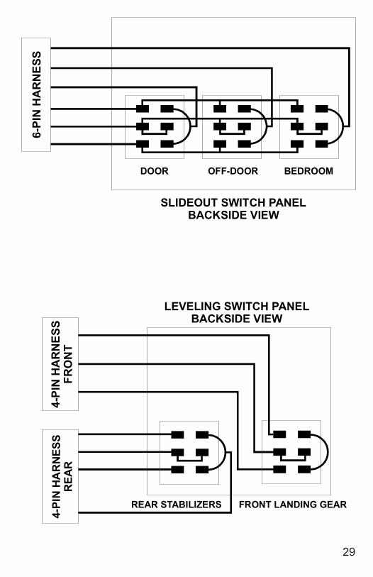
NOTE: Please reference WIRING HARNESS DIAGRAM - Pg. 28
29
6-PI
N H
AR
NES
S4-
PIN
HA
RN
ESS
REA
R4-
PIN
HA
RN
ESS
FRO
NT
SLIDEOUT SWITCH PANELBACKSIDE VIEW
LEVELING SWITCH PANELBACKSIDE VIEW
DOOR OFF-DOOR BEDROOM
REAR STABILIZERS FRONT LANDING GEAR
311413
16
10
12
2 4 6 811
9
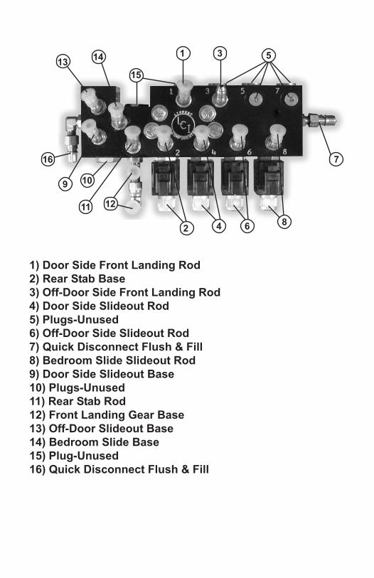
1) Door Side Front Landing Rod2) Rear Stab Base3) Off-Door Side Front Landing Rod4) Door Side Slideout Rod5) Plugs-Unused6) Off-Door Side Slideout Rod7) Quick Disconnect Flush & Fill8) Bedroom Slide Slideout Rod9) Door Side Slideout Base10) Plugs-Unused11) Rear Stab Rod12) Front Landing Gear Base13) Off-Door Slideout Base14) Bedroom Slide Base15) Plug-Unused16) Quick Disconnect Flush & Fill
7
15
5
ORDERING PARTS
To assist the customer service when ordering parts, please provide the followinginformation:
1. Your Name
2. Company Name
3. Phone Number
4. Shipping Address
5. Billing Address
6. Purchase Order Number
7. Coach A. Serial # and/or VIN # B. Make C. Model
8. Part Number
9. Description
10. Quantity
Please take your coach to an authorized service center for repairs. Systemsthat have been modified, adjusted, repaired or augmented by a party otherthan an authorized service center may void any warranty claim with LippertComponents, Inc.