SmartMonitor 2 PS SmartMonitor 2 PSL Professional … · SmartMonitor 2 PSL Professional...
189
SmartMonitor 2 PS SmartMonitor 2 PSL Professional Operator’s Manual
Transcript of SmartMonitor 2 PS SmartMonitor 2 PSL Professional … · SmartMonitor 2 PSL Professional...

SmartMonitor 2 PSSmartMonitor 2 PSLProfessional Operator’s Manual

Warranty
Children’s Medical Ventures, LLC warrants that the monitor will be free from defects in materials and workmanship for a period of two years from the time of purchase. Children’s Medical Ventures, LLC accessories are warranted to be free of defects in materials and workmanship for a period of 90 days from the time of purchase.
The Children’s Medical Ventures, LLC equipment and authorized accessories are designed to function as described in the operator’s manual. The user/owner of this equipment shall have sole responsibility and liability for any injury to persons or damage to property (including this equipment) resulting from• Operationnotinaccordancewithsuppliedoperatinginstructions;• Maintenancenotinaccordancewithauthorizedmaintenance/operationalinstructions;• Servicebyanyoneotherthanafactoryauthorizedservicerepresentative;• Modificationoftheequipmentoraccessories;or• Useofdamagedorunauthorizedcomponentsandaccessories.
THISLIMITEDWARRANTYISINLIEUOFANYANDALLOTHERWARRANTIES,EX-PRESSEDORIMPLIED,INCLUDINGWITHOUTLIMITATIONIMPLIEDWARRANTIESOFMERCHANTABILITYANDFITNESSFORAPARTICULARPURPOSE;TOTHEEX-TENTTHATSTATEORFEDERALLAWPROHIBITSEXCLUSIONSOFIMPLIEDWAR-RANTIES,ANYSUCHIMPLIEDWARRANTYIMPOSEDBYLAWSHALLBELIMITEDTOAPERIODOFNINETY(90)DAYSFROMTHEDATEOFTHEINITIALPURCHASEFROMChildren’s Medical Ventures, LLC.
User/OWner respOnsibility
This Philips Children’s Medical Ventures equipment and the authorized accessories are designed to work as described in the operator’s manual. The user(s) of this equipment should not use parts that have failed, exhibit excessive wear, are contaminated, or are otherwise ineffective. The monitor and its accessoriesshouldnotbemodified.Thefollowinglistincorporatestheowner’sresponsibilities:
• Periodiccheck,maintenance,andcalibrationofequipment;• Replacementofcomponentsasrequiredforsafeandreliableoperation;• ReplacementofineffectivepartswithpartssuppliedbyPhilipsChildren’sMedicalVentures;• Equipmentwhichisnotfunctioningproperlymustnotbeuseduntilallnecessarymaintenance
hasbeencompletedandafactory-authorizedservicerepresentativehascertifiedtheequipmentasreadyforuse;
• Themonitorandanyofitsaccessoriesshouldnotbemodified;• Asageneralrule,theproperperformanceofthismonitorshouldbeverifiedwithaPhilipsChil-
dren’sMedicalVenturesModel5000SimulatoraccordingtotheCheckoutProcedureManualbetween each patient use and/or every 6 to 12 months, whichever is more frequent.
Theuserofthisequipmentisresponsibleforreading,understanding,andfollowingtheWarningandCaution statements throughout this manual.
©2012KoninklijkePhilipsElectronicsN.V.Allrightsreserved.

1SmartMonitor 2 PS Professional Manual
SmartMonitor 2 PS

2 SmartMonitor 2 PS Professional Manual
Manufactured forChildren’s Medical Ventures, LLC191 Wyngate DriveMonroeville, PA 15146 USA
0086
Respironics DeutschlandGewerbestrasse 1782211 Herrsching, Germany

3SmartMonitor 2 PS Professional Manual
Table of ConTenTs
IntroductIon ....................................................................................................................................7
unpackIng and InspectIon ..............................................................................................7
about thIs Manual .........................................................................................................7
IndIcatIons for use .........................................................................................................7
suMMary of clInIcal perforMance evaluatIon............................................................8
study desIgn ............................................................................................................8
Methods ...................................................................................................................8
WarnIngs and cautIons .............................................................................................................. 13
WarnIngs ....................................................................................................................... 13
cautIons ........................................................................................................................ 15
hoMecare provIder preparatIon for hoMe setup .................................................................... 16
hoW does the sMartMonItor 2 ps Work? .............................................................................. 17
syMbols table ........................................................................................................ 18
fcc part 68 telecoM InforMatIon ............................................................................ 20
regIstratIon nuMber and ren ........................................................................... 20
usoc Jack ............................................................................................................ 20
coMplIant accessorIes ......................................................................................... 20
nuMber of rens ................................................................................................... 20
changes In servIce ................................................................................................ 20
probleMs ................................................................................................................ 21
repaIrs .................................................................................................................... 21
party lInes ............................................................................................................ 21
Industry canada requIreMents .................................................................................. 21
Ic abbrevIatIon ..................................................................................................... 21
ren ........................................................................................................................ 21
Industry canada cs-03 notIce ........................................................................ 22
fcc part 15 ........................................................................................................ 22
gettIng to knoW the MonItor .................................................................................................... 23
sMartMonItor 2 ps features ..................................................................................... 24
top panel features ............................................................................................... 24
front panel features ........................................................................................... 25
spo2 lIghts ........................................................................................................... 25
speaker ................................................................................................................... 26

4 SmartMonitor 2 PS Professional Manual
systeM lIghts .........................................................................................................26
sIde panel features .......................................................................................................26
self-test connector .............................................................................................26
MeMory card (optIonal) .....................................................................................27
back panel features......................................................................................................27
nurse call (optIonal) ..........................................................................................27
ModeM (optIonal) ................................................................................................27
I/o connectIons ....................................................................................................28
dc poWer ...............................................................................................................28
stand ..............................................................................................................................28
settIng alarM and recordIng lIMIts...........................................................................................29
Manual setup ................................................................................................................29
the sMartMonItor 2 ps paraMeters..........................................................................................31
systeM setup Menu .......................................................................................................................41
vIeW Menu Mode ...........................................................................................................43
usIng auxIlIary equIpMent ...........................................................................................43
usIng nurse call equIpMent ........................................................................................44
patIent setup .................................................................................................................................47
hospItal Mode ..............................................................................................................................53
respondIng to alarMs ..................................................................................................................55
patIent alarM ................................................................................................................55
testIng the alarM ..........................................................................................................55
If an alarM sounds ......................................................................................................56
respondIng to systeM alarMs ....................................................................................59
reducIng false alarMs .................................................................................................61
MonItorIng ....................................................................................................................................63
turnIng the MonItor on ................................................................................................63
turnIng the MonItor off - sIblIng alarM ..................................................................64
MonItorIng breathIng ..................................................................................................65
respIratIon lIght/dIsplay ....................................................................................65
apnea lIght ...........................................................................................................65
MonItorIng heart actIvIty ..........................................................................................66
heart rate lIght/dIsplay ....................................................................................................................................................................65hIgh heart rate lIght ..............................................................................................................................................................................65loW heart rate lIght ..........................................................................................66

5SmartMonitor 2 PS Professional Manual
MonItorIng the patIent’s oxygen concentratIon level ...........................................67
spo2 lIght .............................................................................................................67
hIgh spo2 alarM lIght ........................................................................................68
loW spo2 alarM lIght ........................................................................................68
portable operatIon of the sMartMonItor 2 ps.......................................................................71
chargIng the MonItor’s battery .................................................................................71
sMartMonItor 2 ps battery pack ..............................................................................72
battery InstallatIon InstructIons ...............................................................................72
transferrIng sMartMonItor 2 ps InforMatIon ........................................................................73
MeMory ManageMent In the MonItor ........................................................................73
to recover the old data usIng a MeMory card .............................................73
to recover the old data by doWnloadIng usIng synergy-e .........................73
ModeM doWnload ........................................................................................................74
ModeM auto dIal .................................................................................................74
ModeM auto ansWer In coMMunIcatIons Mode ...............................................75
ModeM auto ansWer In MonItor Mode .............................................................76
transferrIng MonItor data to a MeMory card .......................................................76
transferrIng MonItor data usIng a coMputer .........................................................78
coMMunIcatIons Mode setup ...............................................................................78
carIng for the sMartMonItor 2 ps ...........................................................................................79
cleanIng InstructIons ...................................................................................................79
electrodes ..............................................................................................................79
soft carryIng case ...............................................................................................79
Insect InfestatIon decontaMInatIon procedures ...............................................80
perforMIng a functIonal self-test .............................................................................80
self-test troubleshootIng ...........................................................................................82
troubleshootIng ............................................................................................................................83
specIfIcatIons .................................................................................................................................87
devIce sIze ..............................................................................................................89
electrIcal ratIngs .................................................................................................89
envIronMental condItIons ...................................................................................89
dIsposal ..................................................................................................................89
eMc requIreMents ........................................................................................................................91
glossary.........................................................................................................................................95

6 SmartMonitor 2 PS Professional Manual

7SmartMonitor 2 PS Professional Manual
InTroduCTIon
unpaCkIng and InspeCTIon
When you receive the SmartMonitor 2 PS, unpack the shipping case and do the following:• Carefullyexaminethecontents.• Savetheshippingcarton.• Makesureyouhaveallthenecessaryitemsandthattheyarenotdamaged.• ReportanythingmissingordamagedtoPhilipsChildren’sMedicalVentures.
abouT ThIs Manual
This manual provides all the information you need to set up and operate the SmartMonitor 2 PS and explainshowtouseittomonitorthepatient’svitalfunctions.Carefullyreadandunderstandthismanualbeforeusingthesystem.
IndICaTIons for use
The SmartMonitor 2 PS is intended for use in the continuous monitoring of respiration, heart rate, and SpO2levelsofinfant,pediatric,andadultpatients.Itdetectsandalarmsforperiodsofhighorlowheartrate,highorlowbreathrate,andhighorlowsaturation.Whenusedasaninfantmonitoritisintendedforuseinahomeorhospitalenvironment.Forinfantsonly,itmonitorsandalarmsforcentralapneas.Whenusedasapediatricoradultmonitor,itisintendedforuseinahospitalenviron-ment.
WhaT Is The purpose of The sMarTMonITor 2 ps?SmartMonitor2PSisanapneamonitordesignedtomonitorandrecordthepatient’sbreathing(respi-ration),heart(cardiac)activityandSpO2(functionaloxygenconcentration)levels.Themonitoralertsyouifanyoftheseactivitiesexceedthelimitsprescribedbythephysician.
Patient alarm limits are set by the health care professional before the monitor is delivered to the pa-tient.Duringmonitoring,whenthebreathingeffort,heartactivityandSpO2 level are not within these setboundaries,anindicatorlightcomesonandanalarmsounds.Thismanualexplainshowtosetupthemonitorhowtomonitorthepatient,andhowtotransferinformation.
OtherdevicesmaybeusedwiththeSmartMonitor2PS.Refertothesection“UsingAuxiliaryEquip-ment”formoreinformation.

8 SmartMonitor 2 PS Professional Manual
suMMary of ClInICal perforManCe evaluaTIon
NOTE: The following study involved the SmartMonitor 2 predicate device and is being used as the basis for perfor-mance evaluation of the SmartMonitor 2 PS. The study was done with infant patients only.
TheSmartMonitor2wasevaluatedinaclinicalstudyaccordingtothemostrecentFDArecommenda-tions.TheserecommendationsareavailableintheGuidanceforApneaMonitor510(k)submission.
sTudy desIgn
Thiswasamulti-center,prospective,non-randomizedstudycarriedoutatsixclinicalsitesintheUnitedStates.Infantsinnurseriesandothersettingsappropriateforattendedmonitoring,whowereconsidered to be appropriate candidates for cardio-respiratory monitoring, were recruited and enrolled inthestudy.
MeThods
Enrollmentwascompetitive,andeachsitewasinstructedtocontinuepatientenrollmentuntilasamplesizeofatleast100qualifiedcentralapneaswasobtained.
InClusIon CrITerIa
Spontaneouslybreathing,newborninfant(lessthanorequalto12monthsofage),eithergenderwithoutregardtoethnicity.
Appropriatecandidateforcardio-respiratorymonitoringincludinganyoneormoreofthefollowing:• diagnosisofcardiac,respiratoryorneurologicaldisease• witnessedorsuspectedepisodesofapneaorperiodicbreathing• gestationalagelessthanorequalto36weeks• historyofsibling(s)experiencingALTE’sorSIDS
• patientsrequiringsupplementaloxygen
exClusIon CrITerIa
Anycandidatewithoneormoreofthefollowingwasexcludedfromenrollment:• presenceofanartificialairway• receivingmechanicalventilation• receivingcontinuouspositiveairwaypressure(CPAP)• presenceofacardiacordiaphragmaticpacemaker
EachpatientwasconnectedtoadataacquisitionsystemthatincludedthePhilipsChildren’sMedicalVenturesSmartMonitorandSmartMonitor2,andtheAlicesystem.Respirationandheartratesignalswererecordedusinginfantelectrocardiogramelectrodes.TheAlicesystemwasusedtogatherphysi-ologicalsignalsandrecordsignalsforairflow,breathingeffort,andmovement.

9SmartMonitor 2 PS Professional Manual
AllAlicesystemdatawerereviewedbyaqualified,credentialedclinicianusinganAlicepolysomno-graphsystem.Waveformsweremanuallyreviewedandscoredonanelectronicmedium.Thebeat/breath detection and alarm channels from the SmartMonitor and SmartMonitor 2 were hidden prior toscoringbytheclinician.Theclinicianidentifiedapnea,bradycardia,andtachycardiaeventsontheAlicesystem.
EventswereidentifiedasrequiredbytheGuidanceforInfant/ChildApneaMonitor510(k)Submis-sions,released2002.
resulTs
SummaryofResults
ComparedtotheSmartMonitor,theSmartMonitor2identified6.8%moreapneas.TheSmartMoni-tor2alsohad12.3%fewerfalsealarmsandmissed6.8%fewercentralapneasthantheSmartMonitor.TheresultsofthisstudydemonstratethatthenewSmartMonitor2issubstantiallyequivalenttothepredicateSmartMonitor.Adetailedbreakdownofstudyresultsisprovidedinthefollowingsections.reCruITMenT suMMary
To T a l # e n r o l l e d # ev a l u a T e d # W I T h 1 o r M o r e C e n T r a l a p n e a s
To T a l # o f a p n e a s I n a n a l y s I s
54 patients 52 patients 35 patients 142
Twopatientswereenrolledbutnotincludedintheevaluation.Onlythefirstsixapneaswereusedfromanyindividualpatient.
deMographIC suMMary
e T h n I C I T y
C l I n I C a l s I T e
n u M b e r o f pa T I e n T s
# M a l e
# fe M a l e
C a u C a s I a n a f r I C a n a M e r I C a n
a s I a n h I s p a n I C o T h e r M e a n b I r T h We I g h T ( g r a M s )
M e a n g e s T a T I o n a l a g e ( We e k s )
Site #1 10 6 4 10 0 0 0 0 1779.70 31.10
Site #2 5 4 1 3 2 0 0 0 2340.40 32.80
Site #3 10 2 8 2 2 2 3 1 3746.90 39.20
Site #4 7 3 4 4 2 0 1 0 1387.00 30.00
Site #5 13 4 9 8 1 0 4 0 1504.46 29.77
Site #6 7 5 2 6 1 0 0 0 2565.43 34.86
Total 52 24 28 33 8 2 8 1 2220.65 (Mean Value)
32.95 (Mean Value)
10 SmartMonitor 2 PS Professional Manual
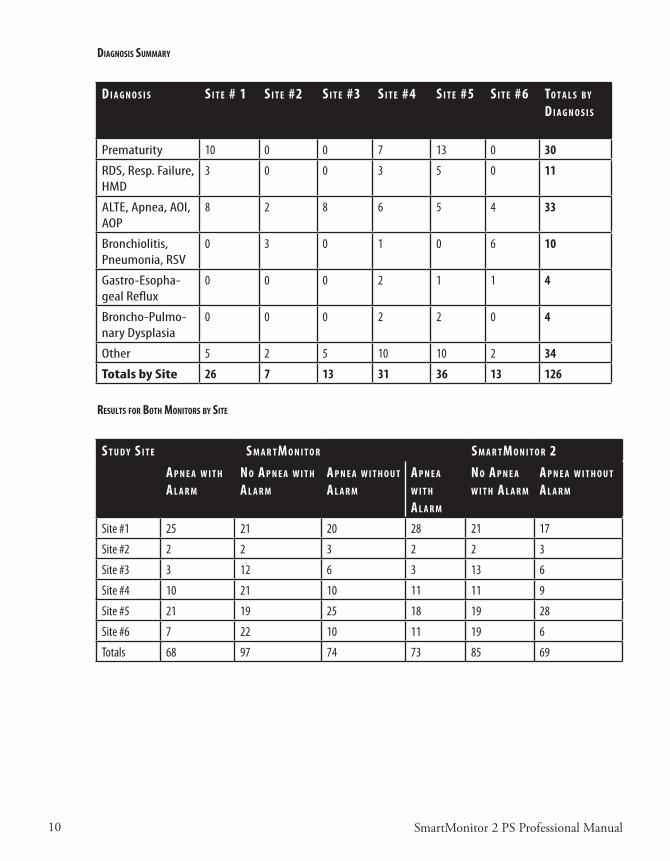
dIagnosIs suMMary
d I a g n o s I s s I T e # 1 s I T e #2 s I T e #3 s I T e #4 s I T e #5 s I T e #6 To T a l s b y d I a g n o s I s
Prematurity 10 0 0 7 13 0 30
RDS, Resp. Failure, HMD
3 0 0 3 5 0 11
ALTE, Apnea, AOI, AOP
8 2 8 6 5 4 33
Bronchiolitis, Pneumonia, RSV
0 3 0 1 0 6 10
Gastro-Esopha-geal Reflux
0 0 0 2 1 1 4
Broncho-Pulmo-nary Dysplasia
0 0 0 2 2 0 4
Other 5 2 5 10 10 2 34
Totals by Site 26 7 13 31 36 13 126
resulTs for boTh MonITors by sITe
s T u d y s I T e s M a r T M o n I T o r s M a r T M o n I T o r 2a p n e a W I T h a l a r M
n o a p n e a W I T h a l a r M
a p n e a W I T h o u T a l a r M
a p n e a W I T h a l a r M
n o a p n e a W I T h a l a r M
a p n e a W I T h o u T a l a r M
Site #1 25 21 20 28 21 17
Site #2 2 2 3 2 2 3
Site #3 3 12 6 3 13 6
Site #4 10 21 10 11 11 9
Site #5 21 19 25 18 19 28
Site #6 7 22 10 11 19 6
Totals 68 97 74 73 85 69

11SmartMonitor 2 PS Professional Manual
analysIs of resulTs
s M a r T M o n I T o r
a p n e a W I T h a l a r M
s M a r T M o n I T o r 2 a p n e a W I T h a l a r M
d I f f e r e n C e (s M a r T M o n I T o r 2 – s M a r T M o n I T o r )
% d I f f e r e n C e
68 73 5 6.8
The sensitivity for SmartMonitor is 100*68/142 = 47.89% with 95% confidence limits (39.44%, 56.42%). The positive predictive value for SmartMonitor is 100*68/165 = 41.21% with exact 95% confidence limits (33.62%, 49.13%). The sensitivity for SmartMonitor 2 is 100*73/142 = 51.41% with 95% confidence limits (38.25%, 54.30%).The positive predictive value of SmartMonitor 2 is 100*73/158 = 46.20% with exact 95% confidence limits (38.25%, 54.30%).
s M a r T M o n I T o r n o a p n e a W I T h a l a r M
(fa l s e a l a r M )
s M a r T M o n I T o r 2 n o a p n e a W I T h a l a r M
(fa l s e a l a r M )
d I f f e r e n C e (s M a r T M o n I T o r 2 – s M a r T M o n I T o r )
% d I f f e r e n C e
97 85 -12 -12.3%
The false apnea rate for SmartMonitor is 97/(95.95) = 1.01. The false apnea rate for SmartMonitor 2 is 85/95.95 = 0.89.
s M a r T M o n I T o r a p n e a W I T h n o a l a r M
(M I s s e d ev e n T )
s M a r T M o n I T o r 2 a p n e a W I T h n o a l a r M
(M I s s e d ev e n T )
d I f f e r e n C e (s M a r T M o n I T o r 2 – s M a r T M o n I T o r )
% d I f f e r e n C e
74 69 -5 -6.8%

12 SmartMonitor 2 PS Professional Manual
13SmartMonitor 2 PS Professional Manual
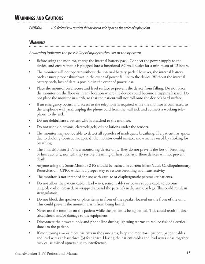
WarnIngs and CauTIons
CAUTION! U.S. federal law restricts this device to sale by or on the order of a physician.
WarnIngs
A warning indicates the possibility of injury to the user or the operator.
• Beforeusingthemonitor,chargetheinternalbatterypack.Connectthepowersupplytothedevice,andensurethatitispluggedintoafunctionalACwalloutletforaminimumof12hours.
• Themonitorwillnotoperatewithouttheinternalbatterypack.However,theinternalbatterypackensurespropershutdownintheeventofpowerfailuretothedevice.Withouttheinternalbatterypack,lossofdataispossibleintheeventofpowerloss.
• Placethemonitoronasecureandlevelsurfacetopreventthedevicefromfalling.Donotplacethemonitoronthefloororinanylocationwherethedevicecouldbecomeatrippinghazard.Donotplacethemonitorinacrib,sothatthepatientwillnotrollontothedevice’shardsurface.
• Ifanemergencyoccursandaccesstothetelephoneisrequiredwhilethemonitorisconnectedtothe telephone wall jack, unplug the phone cord from the wall jack and connect a working tele-phonetothejack.
• Donotdefibrillateapatientwhoisattachedtothemonitor.• Donotuseskincreams,electrodegels,oilsorlotionsunderthesensors.• Themonitormaynotbeabletodetectallepisodesofinadequatebreathing.Ifapatienthasapnea
duetochoking(obstructiveapnea),themonitorcouldmistakemovementcausedbychokingforbreathing.
• TheSmartMonitor2PSisamonitoringdeviceonly.Theydonotpreventthelossofbreathingorheartactivity,norwilltheyrestorebreathingorheartactivity.Thesedeviceswillnotpreventdeath.
• AnyoneusingtheSmartMonitor2PSshouldbetrainedincurrentinfant/adultCardiopulmonaryResuscitation(CPR),whichisaproperwaytorestorebreathingandheartactivity.
• Themonitorisnotintendedforusewithcardiacordiaphragmaticpacemakerpatients.• Donotallowthepatientcables,leadwires,sensorcablesorpowersupplycabletobecome
tangled,coiled,crossed,orwrappedaroundthepatient’sneck,arms,orlegs.Thiscouldresultinstrangulation.
• Donotblockthespeakerorplaceitemsinfrontofthespeakerlocatedonthefrontoftheunit.Thiscouldpreventthemonitoralarmfrombeingheard.
• Neverusethemonitoronthepatientwhilethepatientisbeingbathed.Thiscouldresultinelec-tricalshockand/ordamagetotheequipment.
• Disconnectthepowersupplyandphonelineduringlightningstormstoreduceriskofelectricalshocktothepatient.
• Ifmonitoringtwoormorepatientsinthesamearea,keepthemonitors,patient,patientcablesandleadwiresatleastthree(3)feetapart.Havingthepatientcablesandleadwiresclosetogethermaycausemissedapneasduetointerference.

14 SmartMonitor 2 PS Professional Manual
• DonotconnectthepatienttothemonitorifthemonitorisplacedintheCommunicationsMode.Thealarmsdonotworkwhenthemonitorisinthismode.
• Donotusethemonitoratthesametimeasotherimpedancemonitors.Thismaycausemissedapneasduetointerference.
• Donotrockthepatientorsleepinthesamebedwiththepatientwhilemonitoring.Touchingormovingnearthepatient,monitor,orcablescouldcausethemonitortomissapneas.
• Inspectthepowercordsandcablesoftenforanysignsofdamage.Replaceadamagedcordorcableimmediately.
• Donotusenon-safetystyleleadwiresandpatientcableconfigurationswiththismonitor.Theirusemayposeariskofsevereelectricalshockordeath.Refertotheinstructionsinthismanualtoensureproperconnections.UseonlyPhilipsChildren’sMedicalVenturesrecommendedsafetyleadwires,patientcables,electrodesandsensors.
• PinsofconnectorsidentifiedwiththeESDwarningsymbolshouldnotbetouched.Connec-tionsshouldnotbemadetotheseconnectorsunlessESDprecautionaryproceduresareused.Precautionaryproceduresincludemethodstopreventbuild-upofelectrostaticdischarge(e.g.,airconditioning,humidification,conductivefloorcoverings,non-syntheticclothing),dischargingone’sbodytotheframeoftheequipmentorsystemortoearthoralargemetalobject,andbond-ingoneselfbymeansofawriststraptotheequipmentorsystemortoearth.
• Donottouchthedeviceandthepatientsimultaneously.• Theconductivepartsofelectrodesandpatientcablesshouldnotcontactotherconductiveparts,
includingearth.• TheSpO2sensorsitemustbechangedeveryfour(4)hours.Note:Exerciseextremecautionwith
poorly perfused patients; skin erosion and pressure necrosis can be caused when the sensor is not frequentlymoved.Assessthesiteatleasteverytwo(2)hourswithpoorlyperfusedpatients.
• IftheSpO2sensorisdamagedinanyway,discontinueuseimmediately.• Topreventdamage,donotsoakorimmersetheSpO2sensorinanyliquidsolution.Donotat-
tempttosterilize.• IntravasculardyesmayleadtoinaccurateSpO2measurements.• ElevatedlevelsofCarboxyhemoglobin(COHb)mayleadtoinaccurateSpO2measurements.• ElevatedlevelsofMethemoglobin(MetHb)willleadtoinaccurateSpO2measurements.• FailuretoapplytheSpO2sensorproperlymaycauseincorrectmeasurements.• DonotusethemonitorortheSpO2sensorduringMRIscanning.• AvoidplacingtheSpO2sensoronanyextremitywithanarterialcatheterorbloodpressurecuff.• DonotuseduringHighFrequencysurgicalprocedures.• Explosionhazard.Donotusethemonitorinthepresenceofflammableanestheticsorotherflam-
mablesubstancesincombinationwithair,oxygen-enrichedenvironments,ornitrousoxide.• Ifanalarmconditionoccurswhilethealarmsilenceperiodisactive,theonlyalarmindications
willbevisualdisplaysandsymbolsrelatedtothealarmcondition.• Themonitoristobeoperatedbyqualifiedpersonnelonly.Thismanual,accessorydirectionsfor
use,allprecautionaryinformation,andspecificationsshouldbereadbeforeuse.
15SmartMonitor 2 PS Professional Manual
• Donotusedamagedpatientcables.Donotimmersethepatientcablesinwater,solvents,orcleaningsolutions.(Thepatientcableconnectorsarenotwaterproof.)Donotsterilizebyirradia-tion,steamorethyleneoxide.Seethecleaninginstructionsinthedirectionsforuseforreusablepatientcables.
• TheNurseCallfeatureofthisdeviceisforconvenienceonlyinamedicallysupervisedenviron-ment.TheaudibleindicationprovidedbytheNurseCallsystemisnottoberelieduponastheprimaryindicationoftheoperatingstateofthedeviceorofpatientevents.
• TheNurseCallfeatureshouldbeconsideredabackuptothemonitordevice’sprimaryalarmsystem.TheoperatorshouldnotrelysolelyontheNurseCallfeature.
CauTIons
A caution indicates the possibility of damage to the device.
• Performthefunctionalself-testifthemonitorhasbeenx-rayedbyanairportsecuritycheck.• Donotsendinformationviamodemduringelectricalstorms.Informationcouldbelost,or
equipmentcouldbedamaged.• Handletheleadwirescarefullytopreventthemfrombreakinginsidetheinsulation.Alwaysgrasp
theleadwireatthestrainreliefareatoremovethemfromtheelectrodesorECGpatientcable.• Anyforeignmatterthatgetsintotheenclosureofthemonitormaycausemalfunction.• UseonlyPhilipsChildren’sMedicalVentures-suppliedsensorsandaccessories.Useofotheracces-
soriescoulddegradesignalquality.• Ifyounoticeanyunexplainedchangesintheperformanceofthisdevice,ifitismakingunusual
or harsh sounds, if the device is dropped or mishandled, if water is spilled into the enclosure, or if theenclosureisbroken,discontinueuseandcontactyourhomecareprovider.
• Ifthepatientisbreathingquietlyandtherespirationlightflashesmoreorfewertimesthanthepatientbreathes,contactPhilipsChildren’sMedicalVenturesforservice.
• Insomelocations,themonitorwillnotworkproperly.Ifthemonitorisaffectedbyexternalinterferenceinthearea,youmaynotbeabletousethemonitor.ContactPhilipsChildren’sMedi-calVenturesforfurtherassistance.Useofathird(RL)electrodeandleadwireisnormallynotrequiredbutmayhelpreduceexcessivefalselowheartratealarms.
16 SmartMonitor 2 PS Professional Manual
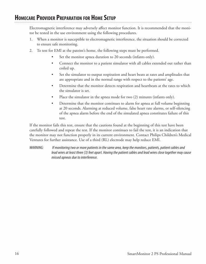
hoMeCare provIder preparaTIon for hoMe seTup
Electromagneticinterferencemayadverselyaffectmonitorfunction.Itisrecommendedthatthemoni-torbetestedintheuseenvironmentusingthefollowingprocedures.1. Whenamonitorissusceptibletoelectromagneticinterference,thesituationshouldbecorrected
toensuresafemonitoring.2. TotestforEMIatthepateint’shome,thefollowingstepsmustbeperformed.
• Setthemonitorapneadurationto20seconds(infantsonly).• Connectthemonitortoapatientsimulatorwithallcablesextendedoutratherthan
coiledup.• Setthesimulatortooutputrespirationandheartbeatsatratesandamplitudesthat
areappropriateandinthenormalrangewithrespecttothepatients’age.• Determinethatthemonitordetectsrespirationandheartbeatsattheratestowhich
thesimulatorisset.• Placethesimulatorintheapneamodefortwo(2)minutes(infantsonly).• Determinethatthemonitorcontinuestoalarmforapneaatfullvolumebeginning
at20seconds.Alarmingatreducedvolume,falseheartratealarms,orself-silencingof the apnea alarm before the end of the simulated apnea constitutes failure of this test.
Ifthemonitorfailsthistest,ensurethatthecautionsfoundatthebeginningofthistesthavebeencarefullyfollowedandrepeatthetest.Ifthemonitorcontinuestofailthetest,itisanindicationthatthemonitormaynotfunctionproperlyinitscurrentenvironment.ContactPhilipsChildren’sMedicalVenturesforfurtherassistance.Useofathird(RL)electrodemayhelpreduceEMI.
WARNING: If monitoring two or more patients in the same area, keep the monitors, patients, patient cables and lead wires at least three (3) feet apart. Having the patient cables and lead wires close together may cause missed apneas due to interference.
17SmartMonitor 2 PS Professional Manual
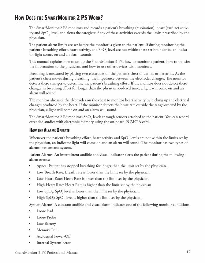
hoW does The sMarTMonITor 2 ps Work?TheSmartMonitor2PSmonitorsandrecordsapatient’sbreathing(respiration),heart(cardiac)activ-ity and SpO2level,andalertsthecaregiverifanyoftheseactivitiesexceedsthelimitsprescribedbythephysician.
Thepatientalarmlimitsaresetbeforethemonitorisgiventothepatient.Ifduringmonitoringthepatient’sbreathingeffort,heartactivity,andSpO2 level are not within these set boundaries, an indica-torlightcomesonandanalarmsounds.
ThismanualexplainshowtosetuptheSmartMonitor2PS,howtomonitorapatient,howtotransfertheinformationtothephysician,andhowtouseotherdeviceswithmonitors.
Breathingismeasuredbyplacingtwoelectrodesonthepatient’schestunderhisorherarms.Asthepatient’schestmovesduringbreathing,theimpedancebetweentheelectrodeschanges.Themonitordetectsthesechangestodeterminethepatient’sbreathingeffort.Ifthemonitordoesnotdetectthesechangesinbreathingeffortforlongerthanthephysician-orderedtime,alightwillcomeonandanalarmwillsound.
The monitor also uses the electrodes on the chest to monitor heart activity by picking up the electrical changesproducedbytheheart.Ifthemonitordetectstheheartrateoutsidetherangeorderedbythephysician,alightwillcomeonandanalarmwillsound.
The SmartMonitor 2 PS monitors SpO2levelsthroughsensorsattachedtothepatient.Youcanrecordextendedstudieswithelectronicmemoryusingtheon-boardPCMCIAcard.
hoW The alarMs operaTe
Wheneverthepatient’sbreathingeffort,heartactivityandSpO2 levels are not within the limits set by thephysician,anindicatorlightwillcomeonandanalarmwillsound.Themonitorhastwotypesofalarms:patientandsystem.
PatientAlarms:Anintermittentaudibleandvisualindicatoralertsthepatientduringthefollowingalarm events:• Apnea:Patienthasstoppedbreathingforlongerthanthelimitsetbythephysician.• LowBreathRate:Breathrateislowerthanthelimitsetbythephysician.• LowHeartRate:HeartRateislowerthanthelimitsetbythephysician.• HighHeartRate:HeartRateishigherthanthelimitsetbythephysician.• LowSpO2: SpO2levelislowerthanthelimitsetbythephysician.• HighSpO2: SpO2levelishigherthanthelimitsetbythephysician.
SystemAlarms:Aconstantaudibleandvisualalarmindicatesoneofthefollowingmonitorconditions:• Looselead• LooseProbe• LowBattery• MemoryFull• AccidentalPower-Off• InternalSystemError
18 SmartMonitor 2 PS Professional Manual
Lights on the monitor indicate which of these conditions exists. See the section “Monitoring” for more information on alarms.
The monitor may also alarm if there is an internal system error. If the monitor alarms and the lights are not illuminated, or if all of the lights are blinking on-and-off, look at the LCD display on the bottom of the unit. If there is an internal error, a code will be displayed and logged into the memory. Discontinue use of the monitor and contact Philips Children’s Medical Ventures Customer Service at 1-800-345-6443.
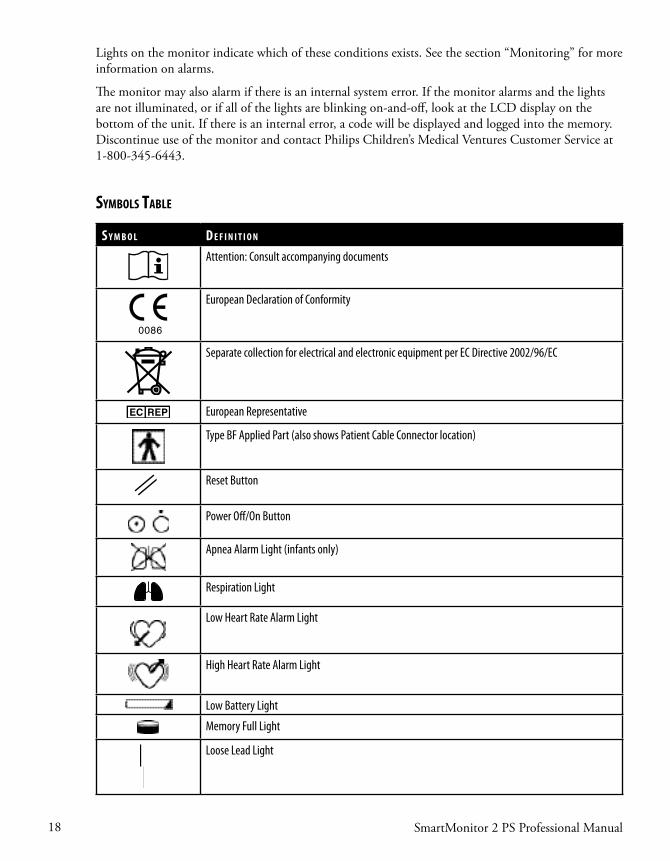
SymbolS Table
S y m b o l D e f i n i T i o n
Attention: Consult accompanying documents
0086
European Declaration of Conformity
Separate collection for electrical and electronic equipment per EC Directive 2002/96/EC
European Representative
Type BF Applied Part (also shows Patient Cable Connector location)
Reset Button
Power Off/On Button
Apnea Alarm Light (infants only)
Respiration Light
Low Heart Rate Alarm Light
High Heart Rate Alarm Light
Low Battery Light
Memory Full Light
Loose Lead Light
19SmartMonitor 2 PS Professional Manual
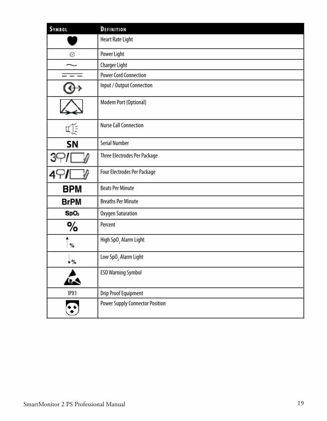
S y m b o l D e f i n i T i o n
Heart Rate Light
Power Light
Charger Light
Power Cord Connection
Input / Output Connection
Modem Port (Optional)
Nurse Call Connection
SN Serial Number
Three Electrodes Per Package
Four Electrodes Per Package
Beats Per Minute
Breaths Per Minute
Oxygen Saturation
Percent
High SpO2 Alarm Light
Low SpO2 Alarm Light
ESD Warning Symbol
IPX1 Drip Proof Equipment
Power Supply Connector Position

20 SmartMonitor 2 PS Professional Manual
fCC parT 68 TeleCoM InforMaTIon
regIsTraTIon nuMber and ren
Thismonitor’smodemcomplieswithPart68oftheFederalCommunicationCommission(FCC)rules.Onthebottomofthemonitorisalabelthatcontains,amongotherinformation,theFCCreg-istrationnumberandtheringerequivalencenumber(REN)forthemodem.Ifrequested,thisnumbermustbeprovidedtothetelephonecompany.TheFCCregistrationnumberis:CMVMM05B4000-20
usoC JaCk
Themonitor’smodemisdesignedtobeusedonstandarddevicetelephonelines.ThesuitableUSOCjack(UniversalServiceOrderCodeconnectingarrangement)forthismodemisRJ11CorRJ11W(singleline).
CoMplIanT aCCessorIes
ThetelephonecordandmodularplugprovidedwiththisequipmentarecompliantwithapplicableFederalCommunicationCommission(FCC)rules.Thisequipmentisdesignedforconnectiontothepremiseswiringandtelephonenetworkusingacompatiblemodularjackthatisalsocompliant.Seeinstallationinstructionsfordetails.
nuMber of rens
TheRingerEquivalenceNumber(REN)isusedtodeterminethenumberofdevicesthatmaybecon-nectedtoatelephoneline.ExcessiveRENsonatelephonelinemayresultinthedevicesnotringinginresponsetoanincomingcall.Inmostbutnotallareas,thesumofRENsshouldnotexceedfive(5.0).Tobecertainofthenumberofdevicesthatmaybeconnectedtoaline,asdeterminedbythetotalRENs,contactthelocaltelephonecompany.
CAUTION: If the modem causes harm to the telephone network, the telephone company will notify you in advance that temporary discontinuance of service may be required. But if advance notice is not practical, the telephone company will notify you as soon as possible. Also, you will be advised of your right to file a complaint with the Federal Communications Commission (FCC) if you believe filing a complaint is necessary.
Changes In servICe
Thetelephonecompanymaymakechangesinitsfacilities,equipment,operations,orproceduresthatcouldaffecttheoperationofthisequipment.Ifthishappens,thetelephonecompanywillprovideadvancenoticeinorderforyoutomakenecessarymodificationstomaintainuninterruptedservice.
21SmartMonitor 2 PS Professional Manual
probleMs
Iftroubleisexperiencedwiththismodem,pleasecontactyourhomecareproviderorPhilipsChildren’sMedicalVenturesat1-800-345-6443forrepairorwarrantyinformation.Iftheequipmentiscausingharmtothetelephonenetwork,thetelephonecompanymayrequestthatyoudisconnecttheequip-mentuntiltheproblemisresolved.
repaIrs
Norepairsaretobemadebyyou.Wheneveratechnicalproblemoccursthatyoucannothandle,con-tactyourhomecareprovider.Unauthorizedrepairsvoidregistrationandwarranty.
parTy lInes
Connectiontopartylineserviceissubjecttostatetariffs.Contactthestatepublicutilitycommission,publicservicecommissionorcorporationcommissionforinformation.
CAUTION: If your home has specially wired alarm equipment connected to the telephone line, ensure that the installa-tion of the monitor’s modem does not disable your alarm equipment. If you have questions about what will disable alarm equipment, consult your telephone company or a qualified installer.
IndusTry Canada requIreMenTs
IC abbrevIaTIon
ThisequipmentmeetstheapplicableIndustryCanadaTerminalEquipmentTechnicalSpecifications.Thisisconfirmedbytheregistrationnumber.Theabbreviation,IC,beforetheregistrationnumbersig-nifiesthatregistrationwasperformedbasedonaDeclarationofConformityindicatingthatIndustryCanadatechnicalspecificationsweremet.ItdoesnotimplythatIndustryCanadaapprovedtheequip-ment.TheICnumberis:9141A-400020.
ren
TheRingerEquivalenceNumber(REN)forthisterminalequipmentis0.5B.TheRENisanindica-tionofthemaximumnumberofdevicesallowedtobeconnectedtoatelephoneinterface.Thetermi-nationontheinterfacemayconsistofanycombinationofdevicessubjectonlytotherequirementthatthesumoftheRENsofallthedevicesdoesnotexceedfive.

22 SmartMonitor 2 PS Professional Manual
IndusTry Canada Cs-03 noTICe
NOTICE:TheIndustryCanada(IC)labelonthemonitoridentifiescertifiedequipment.Thiscerti-ficationmeansthattheequipmentmeetscertaintelecommunicationsnetworkprotective,operationalandsafetyrequirementsasprescribedintheappropriateTerminalEquipmentTechnicalrequirementsdocument(s).TheDepartmentdoesnotguaranteetheequipmentwilloperatetotheuser’ssatisfaction.
Beforeinstallingthemonitor,usersshouldensurethatitispermissibletobeconnectedtothefacilitiesofthelocaltelecommunicationscompany.Theequipmentmustalsobeinstalledusinganacceptablemethodofconnection.Thecustomershouldbeawarethatcompliancewiththeaboveconditionsmightnotpreventdegradationofserviceinsomesituations.
ThePhilipsChildren’sMedicalVenturesServiceCentershouldcoordinaterepairstocertifiedequip-mentat1-800-345-6443.Anyrepairsoralterationsmadebytheusertothisequipment,orequipmentmalfunctions,maygivethetelecommunicationscompanycausetorequesttheusertodisconnecttheequipment.
Usersshouldensure,fortheirownprotection,thattheelectricalgroundconnectionsofthepowerutility,telephonelines,andinternalmetallicwaterpipesystem,ifpresent,areconnectedtogether.Thisprecautionmaybeparticularlyimportantinruralareas.
CAUTION: Users should not attempt to make such connections themselves, but should contact the appropriate electric inspection authority, or electrician, as appropriate.
fCC parT 15
ThisequipmenthasbeentestedandfoundtocomplywiththelimitsforaClassBdigitaldevice,pur-suanttoPart15oftheFCCrules.Theselimitsaredesignedtoprovidereasonableprotectionagainstharmfulinterferenceinaresidentialinstallation.
Becausethisequipmentgenerates,uses,andcanradiateradiofrequencyenergy,ifitisnotinstalledand used in accordance with the instructions, it may cause harmful interference to radio communica-tions.
However,thereisnoguaranteethatinterferencewillnotoccurinaparticularinstallation.Thiscanbedeterminedbyturningtheequipmentoffandon.Ifthisequipmentdoescauseharmfulinterferencetoradio or television reception, you are encouraged to try to correct the interference by one or more of the following measures:• Reorientorrelocatethereceivingantenna.• Increasetheseparationbetweentheequipmentandreceiver.• Plugtheequipmentintoanoutletonacircuitdifferentfromthattowhichthereceiveriscon-
nected.• Consultthedealeroranexperiencedradio/TVtechnicianforhelp.
ThisdevicecomplieswithPart15oftheFCCrules.Operationofthisdeviceissubjecttothefollow-ing conditions:
(1)Thisdevicemaynotcauseharmfulinterference,and(2)thisdevicemustacceptanyinterferencethatmaycauseundesiredoperation.
CAUTION: Changes or modifications to this unit not expressly approved by the party responsible for compliance could void the user’s authority to operate the equipment.

23SmartMonitor 2 PS Professional Manual
geTTIng To knoW The MonITor1
2
5
6
8
9
10
7 113
4
SpO2%%
Parents’
Guide
When you receive the SmartMonitor 2 PS, make sure that you have all the necessary items and that theyarenotdamaged.ImmediatelyreportanythingmissingordamagedtoPhilipsChildren’sMedicalVentures.
The standard package should include the following:1. SmartMonitor2PS2. SoftCarryingCase3. Parents’Guide4. PowerSupplyandPowerCord.Yournewmonitorissuppliedwithanexternalpowersupply(P/N
1031372)anda3-wireACinputcord.Ifyoudonothaveagrounded(3-wire)poweroutlet,con-tactPhilipsChildren’sMedicalVenturesCustomerServiceat1-800-345-6443toobtaina2-wirepowersupply(P/N1016966)andACinputcord.The3-wiresupplyandthe2-wiresupplybothprovidethesamelevelofoperatorandpatientsafetyaccordingtoIEC60601-1.However,whenthemonitorisusedonapatientwhohasothermedicalequipmentconnectedatthesametime,the 3-wire power supply may provide greater immunity to electrical noise for the monitor and othermedicalequipment.
NOTE: The appearance of the power supply and cord will vary, depending on country of use. In the illustrations in this guide, the power supply is represented by a standard U.S. domestic 2-wire configuration.
5. ECGPatientCable6. OximeterPatientCable7. LeadWires8. Electrodes9. Electrodebelt10. Handle/Stand11. BatteryPack12. SymbolReferenceCard(notshownhere)13. PhoneLineSplitter(notshownhere)(optional)14. PhoneLineCord(notshownhere)(optional)
NOTE: Oximeter sensors are not included in the standard package and need to be ordered separately.
24 SmartMonitor 2 PS Professional Manual
sMarTMonITor 2 ps feaTures
Thissectiondescribesthephysicalfeaturesofthemonitor.
Top panel feaTures
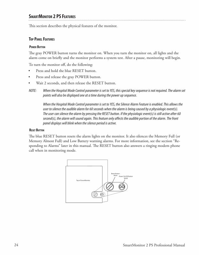
poWer buTTon
ThegrayPOWERbuttonturnsthemonitoron.Whenyouturnthemonitoron,alllightsandthealarmcomeonbrieflyandthemonitorperformsasystemtest.Afterapause,monitoringwillbegin.
Toturnthemonitoroff,dothefollowing:• PressandholdtheblueRESETbutton.• PressandreleasethegrayPOWERbutton.• Wait2seconds,andthenreleasetheRESETbutton.
NOTE: When the Hospital Mode Control parameter is set to YES, this special key sequence is not required. The alarm set points will also be displayed one at a time during the power up sequence.
When the Hospital Mode Control parameter is set to YES, the Silence Alarm Feature is enabled. This allows the user to silence the audible alarm for 60 seconds when the alarm is being caused by a physiologic event(s). The user can silence the alarm by pressing the RESET button. If the physiologic event(s) is still active after 60 second(s), the alarm will sound again. This feature only affects the audible portion of the alarm. The front panel displays will blink when the silence period is active.
reseT buTTon
TheblueRESETbuttonresetsthealarmlightsonthemonitor.ItalsosilencestheMemoryFull(orMemoryAlmostFull)andLowBatterywarningalarms.Formoreinformation,seethesection“Re-spondingtoAlarms”laterinthismanual.TheRESETbuttonalsoanswersaringingmodemphonecallwheninmonitoringmode.

25SmartMonitor 2 PS Professional Manual
fronT panel feaTures
paTIenT InpuT ConneCTors
Twopatientinputconnectorsappearonthemonitor.ThetopconnectorsupportsconnectionoftheSpO2patientcable.ThebottomconnectionisfortheHeart/Respirationpatientcable.
SpO 2
%%
Heart Display RespirationDisplay
SpO2 Display
Heart Lights Respiration LightsOximeter PatientCable ConnectionSpO2 Lights
Speaker Power Charger Low Battery
Memory Full
Loose Lead ECG PatientCable Connection
System Lights
dIsplay of values
Valuesforheartrate,breathrateandSpO2levelareviewablefromthefrontpaneldisplay.YoucanincreasethebrightnessofDisplayValuesonthemonitorbypressingthe or buttons.
NOTE: You can disable this feature through the user interface on the bottom of the monitor. You can also disable the oximeter functionality through the user interface.
respIraTIon lIghTs
The green respiration light blinkswitheachbreaththemonitordetects.Theredapnealightwill come on if the monitor detects a pause in breathing that is longer than the limit set by the physi-cian.
hearT lIghTs
The green heart light blinkswitheachheartbeatthemonitordetects.Theredhighlight comesonwhenthemonitordetectsaheartratehigherthanthelimitsetbythephysician.Theredlowlight comesonwhenthemonitordetectsaheartratelowerthanthelimitsetbythephysician.
spo2 lIghTs
The green SpO2 light will appear solid when the probe is connected to the patient and is moni-toringastrongsignal.AsolidorangelightwillappearifthedeviceismonitoringtheSpO2level.Iftheprobe is disconnected, is not transmitting a signal, or is transmitting a moderate or marginal signal, a red SpO2 lightwillappear.Theredhighlight comes on when the SmartMonitor 2 PS detects an SpO2levelhigherthanthelimitsetbythephysician.Theredlowlight comes on when the SmartMonitor 2 PS detects an SpO2levellowerthanthelimitsetbythephysician.
26 SmartMonitor 2 PS Professional Manual
speaker
Themonitor’sspeakerallowsyoutohearanyalarmthatsoundsduringmonitoring.Thisspeakerusestwointernalbuzzers,andyoumaynoticetwoslightlydifferenttoneswhenthedeviceisalarming.
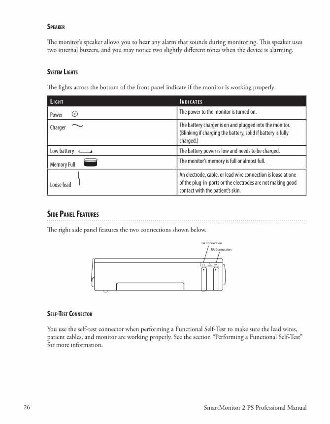
sysTeM lIghTs
The lights across the bottom of the front panel indicate if the monitor is working properly:
l I g h T I n d I C a T e s
Power The power to the monitor is turned on.
Charger The battery charger is on and plugged into the monitor. (Blinking if charging the battery, solid if battery is fully charged.)
Low battery The battery power is low and needs to be charged.
Memory Full The monitor’s memory is full or almost full.
Loose lead
An electrode, cable, or lead wire connection is loose at one of the plug-in-ports or the electrodes are not making good contact with the patient’s skin.
sIde panel feaTures
Therightsidepanelfeaturesthetwoconnectionsshownbelow.
self-TesT ConneCTor
Youusetheself-testconnectorwhenperformingaFunctionalSelf-Testtomakesuretheleadwires,patientcables,andmonitorareworkingproperly.Seethesection“PerformingaFunctionalSelf-Test”formoreinformation.
27SmartMonitor 2 PS Professional Manual
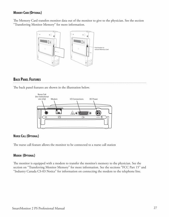
MeMory Card (opTIonal)
TheMemoryCardtransfersmonitordataoutofthemonitortogivetothephysician.Seethesection“TransferringMonitorMemory”formoreinformation.
enterenter
Push button toremove Memory Card
baCk panel feaTures
Thebackpanelfeaturesareshownintheillustrationbelow.
nurse Call (opTIonal)
The nurse call feature allows the monitor to be connected to a nurse call station
ModeM (opTIonal)
Themonitorisequippedwithamodemtotransferthemonitor’smemorytothephysician.Seethesectionon“TransferringMonitorMemory”formoreinformation.Seethesections“FCCPart15”and“IndustryCanadaCS-03Notice”forinformationonconnectingthemodemtothetelephoneline.
28 SmartMonitor 2 PS Professional Manual
I/o ConneCTIons
Thisconnectorconnectsthemonitorwithotherdevices.
EnsurethatthedevicesuseddonotexceedSELV(SafetyExtraLowVoltage)levelsasdescribedinEN60601-1.
dC poWer
UsetheDCPowerconnectorwiththepowercord/batterycharger.Wheneverthemonitorisnotbeingtransported(onbatterypoweronly)itshouldbeconnectedtothebatterycharger.
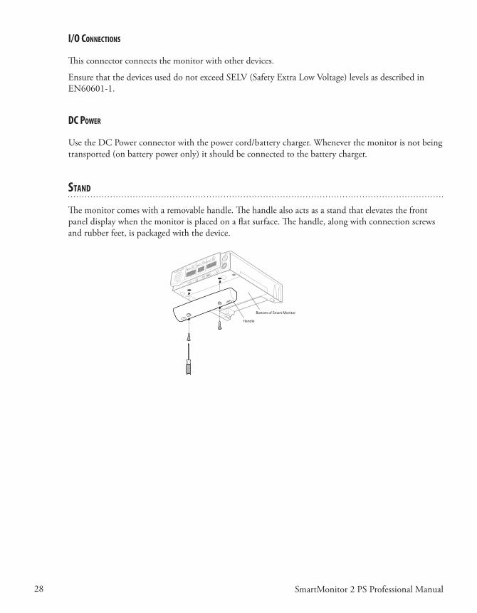
sTand
Themonitorcomeswitharemovablehandle.Thehandlealsoactsasastandthatelevatesthefrontpaneldisplaywhenthemonitorisplacedonaflatsurface.Thehandle,alongwithconnectionscrewsandrubberfeet,ispackagedwiththedevice.

29SmartMonitor 2 PS Professional Manual
seTTIng alarM and reCordIng lIMITs
Themonitorhastheabilitytoprogramalarmandrecordinglimitsasprescribedbythephysician.There are two methods, including direct connect via serial link to a computer or manually through the displayonthebottomofthemonitor.
Manual seTup
Removethedisplaydoorfromthebottomofthemonitor.Beneaththedisplaydoor,youwillfindthedisplayorLCDandthreebuttons.Thesebuttonsareusedtokeyina“Password”intothemoni-tor.Themenusystemhasthreepasswords.Eachpasswordallowsaccesstoadifferentlevelofoptions.ThesethreelevelsareMonitorSetup,SystemSetup,andViewOnly.Thefollowingdiscussestheseindetail.
TheMonitorSetupMenuisusedtoselectallalarmandrecordingsettings.Youcanadjustsettingsmanually,bymodem,orbydirectcommunication.WhenyouaccesstheMonitorSetupMenu,themonitorisinMenumode.
NOTE: The monitor will beep once every 10 seconds to signal that it is powered on and in Menu mode.
ToSetorModifyParametersManually,EnterMenuMode• PressthePOWERbuttontoturnthemonitorON.Afterashortdelay,thedisplaywillread: INITIALIZINGPLEASEWAIT
Memory Display Detail
INITIALIZINGPLEASE WAIT
Then, MENUMODE?ENTERPROPERKEYSEQUENCE• Pressthekeysinthefollowingsequencewithin10seconds: DOWNARROWbutton,UPARROWbutton,UPARROWbutton,ENTERbutton,ENTER
button,ENTERbutton.• ThedisplaywillreadSMARTMONITOR2PSMENUSELECTION.• Themonitor’smenuhasover40entriesthatarepresentedinacontinuousloop.UsetheUPAR-
ROWbuttontodisplaythenextmenuentry.• UsetheDOWNARROWbuttontodisplaytheprecedingmenuentry.• Whentheparameteryouwanttochangeisdisplayed,presstheENTERbutton.Thecurrent
valuefortheparameterdisplayedwillflash.

30 SmartMonitor 2 PS Professional Manual
• Usethe or keytochangetheparametertothedesiredvalue.• Whenthedesiredvalueisdisplayed,presstheENTERbuttontoacceptthevalue.• PresstheUPARROWbuttontochoosethemenupathyouwanttoreview.There are four menu paths to choose from:• AllMenu• AlarmMenu• RecordingMenu• SystemMenu.
Oncethechangesarecompleted,turnthemonitoroffbypressingthefollowingbuttons:• PressandholdtheblueRESETbutton.• PressandreleasethegrayPOWERbutton.• Waittwoseconds,andthenreleasetheRESETbutton.
NOTE: When you power the monitor off and then back on, the new values will be implemented.
When the Hospital Mode Control parameter is set to YES, the special key sequence is not necessary to turn the monitor off.

31SmartMonitor 2 PS Professional Manual
The sMarTMonITor 2 ps paraMeTers
ThefollowingmenuflowisforAllMenus.ThispathencompassesmenusforAlarm,Recording,andSystem.Forinstance,toquicklyaccessanalarmsetting,selecttheAlarmMenu.
StandardvaluesforAlarmsandRecordingparametersappearinbold.
M e n u o p T I o n lCd d I s p l a y d e s C r I p T I o n o f o p T I o n o r I n s T r u C T I o n s M e n u pa T h
View Prior Events VIEW PRIOR EVENTS? This menu option allows the user to view a summary of the ten most recent physiological events via the LCD screen. To view events:• Press the ENTER button to activate.• Press or to change the selection to Yes.
Then press the ENTER button.• Press or to browse through the most
recent events (up to ten).• Press the ENTER button to exit this menu option.
All MenusSystem Menus
Patient Name
PATIENT NAME To enter the Patient Name:• Press the ENTER button to begin entering the
patient name.• Press or to browse through the alphabet
and select the letter you need. When the letter you want appears, press the ENTER button. Press the ENTER button twice to place a space in between the first and last name.
• When you have finished the name, press or until the ^ appears. Then press the ENTER
button.
NOTE: The ^ is just before the letter “a”.
• Press to proceed to the next menu or to move to the previous menu.
All MenusAlarm MenuRecord MenuSystem Menu
Patient Identification Number
PATIENT ID NUMBER To enter the Patient ID:• Press or until Patient ID is displayed.• Press the ENTER button to activate.• Press or to browse through the numbers
and select the digit you need. When the digit you want displays, press the ENTER button.
• When you have finished the ID, press or until the ^ appears. Then press the ENTER button.
NOTE: ^ is just before “0”.
• Press to proceed to the next menu or to move to the previous menu.
All MenusAlarm MenuRecord MenuSystem Menu

32 SmartMonitor 2 PS Professional Manual
M e n u o p T I o n lCd d I s p l a y d e s C r I p T I o n o f o p T I o n o r I n s T r u C T I o n s M e n u pa T h
Standard Alarm Parameters
STD ALARM PARAMETERS
Are SelectedOr
Are Not Selected
• Press the ENTER button to activate.• Press or to change the selection.• When you have your selection displayed, press the
ENTER button.
All MenusAlarm Menu
Standard Record Parameters
STD RECORD PARMS.Are Selected
OrAre Not Selected
• Press the ENTER button to activate.• Press or to change the selection.• When you have your selection displayed, press the
ENTER button.
All MenusRecord Menu
Standard System Parameters
STD SYSTEM PARMS.Are Selected
OrAre Not Selected
• Press the ENTER button to activate.• Press or to change the selection.• When you have your selection displayed, press the
ENTER button.
All MenusSystem Menu
Apnea Alarm Setpoint (Infants only)
APNEA ALARM in seconds
Establishes the amount of time of no respiration detec-tion prior to activation of the apnea alarm.Values:10, 15, 20, 25, 30, 40 secondsStandard value: 20 seconds
All MenusAlarm Menu
Low Breath Rate Alarm Setpoint
LOW BREATH ALARM BrPM
Establishes the alarm set point based on frequency of detected respiratory effort.Values:OFF, 4, 5, 6, 7, 8, 9, 10, 12, 14, 16, 18, 20, 25, 30 breaths per minuteStandard value: OFF
All MenusAlarm Menu
Bradycardia Alarm Setpoint
BRADYCARDIA ALARM BPM
Establishes the LOW heart rate alarm set point based on the average detected ECG signal.Values:40, 50, 60, 70, 80, 90, 100 beats per minuteStandard value: 80 BPM
All MenusAlarm Menu
Bradycardia Alarm Delay
BRADY ALARM DELAY in seconds
Enables a delay to the audible alarmValues:0 or 5 secondsStandard value: 0 seconds
NOTE: If this parameter is set to 5 seconds, the audible alarm will not activate unless the alarm set point is violated for 5 seconds or more.
This is a physician decision and is based on such factors as the known condition of the patient, number of short Bradycardia alarms documented by the monitor, the current Bradycardia alarm set point, and the patient’s average resting heart rate.
All MenusAlarm Menu
33SmartMonitor 2 PS Professional Manual
M e n u o p T I o n lCd d I s p l a y d e s C r I p T I o n o f o p T I o n o r I n s T r u C T I o n s M e n u pa T h
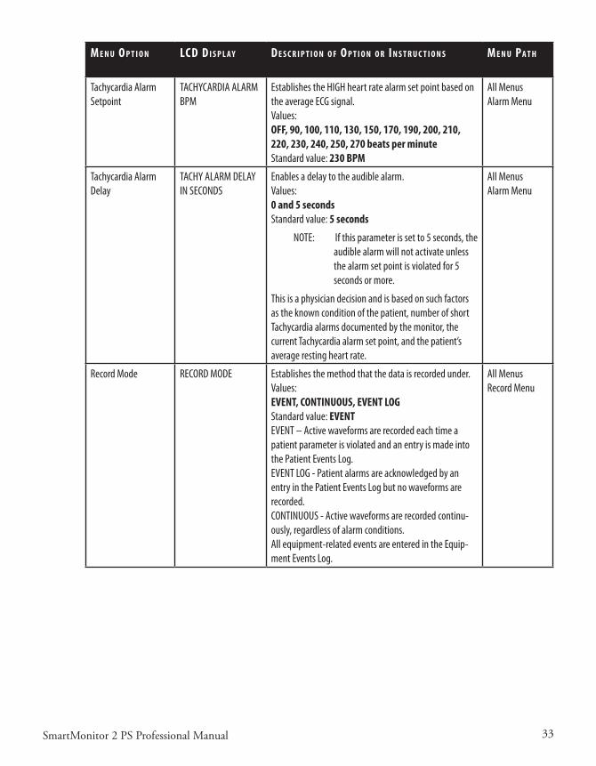
Tachycardia Alarm Setpoint
TACHYCARDIA ALARM BPM
Establishes the HIGH heart rate alarm set point based on the average ECG signal.Values:OFF, 90, 100, 110, 130, 150, 170, 190, 200, 210, 220, 230, 240, 250, 270 beats per minuteStandard value: 230 BPM
All MenusAlarm Menu
Tachycardia Alarm Delay
TACHY ALARM DELAYIN SECONDS
Enables a delay to the audible alarm.Values:0 and 5 secondsStandard value: 5 seconds
NOTE: If this parameter is set to 5 seconds, the audible alarm will not activate unless the alarm set point is violated for 5 seconds or more.
This is a physician decision and is based on such factors as the known condition of the patient, number of short Tachycardia alarms documented by the monitor, the current Tachycardia alarm set point, and the patient’s average resting heart rate.
All MenusAlarm Menu
Record Mode RECORD MODE Establishes the method that the data is recorded under.Values:EVENT, CONTINUOUS, EVENT LOGStandard value: EVENTEVENT – Active waveforms are recorded each time a patient parameter is violated and an entry is made into the Patient Events Log.EVENT LOG - Patient alarms are acknowledged by an entry in the Patient Events Log but no waveforms are recorded.CONTINUOUS - Active waveforms are recorded continu-ously, regardless of alarm conditions. All equipment-related events are entered in the Equip-ment Events Log.
All MenusRecord Menu

34 SmartMonitor 2 PS Professional Manual
M e n u o p T I o n lCd d I s p l a y d e s C r I p T I o n o f o p T I o n o r I n s T r u C T I o n s M e n u pa T h
Apnea for Record APNEA RECORD LIMITin seconds
Allows active waveforms to be recorded during the respi-ratory pauses prior to activation of the Apnea alarm.Values:OFF, 6, 8, 10, 12, 14, 16, 18, 20, 22, 24, 26, 28, 30, 32, 34, 36, 38, 40 secondsStandard value: 16 secondsWhen in Event Mode with the Apnea Alarm set to 20 seconds and the Apnea for Record set to 16 seconds, the system will perform as follows:• For a respiratory pause of <16 seconds, no wave-
forms will be recorded and no alarm will occur.• For a respiratory pause of >16 seconds, but less
than 20 seconds, waveforms will be recorded, but no alarm will occur.
• For a respiratory pause of >20 seconds, waveforms will be recorded and an alarm will occur.
All MenusRecord Menu
Bradycardia for Record
BRADY RECORD LIMIT BPM
Allows active waveforms to be recorded during a brady-cardia event prior to activation of the Bradycardia alarm.Values:OFF, 50, 55, 60, 65, 70, 75, 80, 85, 90, 95, 100 beats per minuteStandard value: OFFWhen in Event Mode with the Bradycardia Alarm set to 70 BPM and the Bradycardia for Record set to 80 BPM, the system will perform as follows:• For a heart rate of >80 BPM, no waveforms will be
recorded and no alarm will occur.• For a heart of >70 BPM and <80 BPM, waveforms
will be recorded but no alarm will occur.• For a heart rate of <70 BPM, waveforms will be
recorded and an alarm will occur.
All MenusRecord Menu
Pre/Post Time PRE/POST TIME in seconds
This parameter allows the user to prescribe both the number of seconds that waveforms are recorded prior to the occurrence of a physiologic event and after the event has terminated. PRE defines the number of seconds that waveforms will be recorded prior to the event.
POST defines the number of seconds that waveforms will be recorded after the event has terminated.Values:30/15, 30/60, 45/45, 60/30, 30/30, 75/15, 60/15, 45/15 secondsStandard value: 30/15 seconds
All MenusRecord Menu

35SmartMonitor 2 PS Professional Manual
M e n u o p T I o n lCd d I s p l a y d e s C r I p T I o n o f o p T I o n o r I n s T r u C T I o n s M e n u pa T h
Impedance Record RECORD IMPEDANCE? This parameter allows the user to select whether or not the respiration waveform will be recorded. Values:YES or NOStandard value: YES
All MenusRecord Menu
Respiration Rate Record
RECORD RESP RATE? This parameter allows the user to select whether or not the Breath-To-Breath and the Average Respiration Rates will be recorded. Values:YES or NOStandard value: YES
All MenusRecord Menu
Heart Rate Record RECORD HEARTRATE? This parameter allows the user to select whether or not the Beat-To-Beat and the Average Heart Rates will be recorded.Values:YES or NOStandard value: YES
All MenusRecord Menu
ECG Record RECORD ECG? This parameter allows the user to select whether or not the ECG waveform will be recorded.Values:YES or NOStandard value: YES
All MenusRecord Menu
Oximeter Control OXIMETER ENABLED This parameter allows the user to disable/enable the internal Oximeter. Values:YES and NOStandard value: YES
All MenusAlarm MenusRecord MenuSystem Menu
Front Panel Control ENABLE PANEL DISPLAY
This parameter allows the user to enable/disable the Front Panel Display. Values:YES and NOStandard value: YES
All MenusSystem Menu
Oximeter Probe Off Functionality
PROBE OFF FUNCTION This parameter allows the user to select what system actions the monitor will take when an “Oximeter Probe Off” condition occurs. Values:No Events Or Alarms – Not documented in equip-ment log, no audible alarmsDo Events, No Alarms – Documented in equipment log, no audible alarm soundsDo Events, Do Alarms – Event documented in log and alarm soundsStandard value: Do Events, Do Alarms
All MenusSystem Menu
36 SmartMonitor 2 PS Professional Manual
M e n u o p T I o n lCd d I s p l a y d e s C r I p T I o n o f o p T I o n o r I n s T r u C T I o n s M e n u pa T h
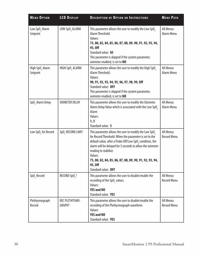
Low SpO2 Alarm Setpoint
LOW SpO2 ALARM This parameter allows the user to modify the Low SpO2 Alarm Threshold. Values:75, 80, 82, 84, 85, 86, 87, 88, 89, 90, 91, 92, 93, 94, 95, OffStandard value: 85This parameter is skipped if the system parameter, oximeter enabled, is set to NO
All MenusAlarm Menu
High SpO2 Alarm Setpoint
HIGH SpO2 ALARM This parameter allows the user to modify the High SpO2 Alarm Threshold.Values:90, 91, 92, 93, 94, 95, 96, 97, 98, 99, OffStandard value: OFFThis parameter is skipped if the system parameter, oximeter enabled, is set to NO
All MenusAlarm Menu
SpO2 Alarm Delay OXIMETER DELAY This parameter allows the user to modify the Oximeter Alarm Delay Value which is associated with the Low SpO2 AlarmValues:1, 5Standard value: 5
All MenusAlarm Menu
Low SpO2 for Record SpO2 RECORD LIMIT This parameter allows the user to modify the Low SpO2 for Record Threshold. When the parameter is set to the default value, after a Probe Off/Low SpO2 condition, the alarm will be delayed for 5 seconds to allow the oximeter reading to stabilize.Values:75, 80, 82, 84, 85, 86, 87, 88, 89, 90, 91, 92, 93, 94, 95, OffStandard value: OFF
All MenusRecord Menu
SpO2 Record RECORD SpO2? This parameter allows the user to disable/enable the recording of the SpO2 values.Values:YES and NOStandard value: YES
All MenusRecord Menu
Plethysmograph Record
REC PLETHYSMO-GRAPH?
This parameter allows the user to disable/enable the recording of the Plethysmograph waveform. Values:YES and NOStandard value: YES
All MenusRecord Menu

37SmartMonitor 2 PS Professional Manual
M e n u o p T I o n lCd d I s p l a y d e s C r I p T I o n o f o p T I o n o r I n s T r u C T I o n s M e n u pa T h
Pulse Rate Record RECORD PULSE RATE? This parameter allows the user to disable/enable the recording of the Oximeter Pulse Rate values. Values:YES and NOStandard value: NO
All MenusRecordMenu
Auxiliary 1 Record RECORD AUXILIARY 1 This parameter allows the user to select whether or not waveforms will be recorded on Auxiliary 1.Standard value: OFFFor additional information, refer to the “Auxiliary Signal Interface” section of this manual.
All MenusRecord Menu
Auxiliary 2 Record RECORD AUXILIARY 2 This parameter allows the user to select whether or not waveforms will be recorded on Auxiliary 2.Standard value: OFFFor additional information, refer to the “Auxiliary Signal Interface” section of this manual.
All MenusRecord Menu
Auxiliary 3 Record RECORD AUXILIARY 3 This parameter allows the user to select whether or not waveforms will be recorded on Auxiliary 3.Standard value: OFFFor additional information, refer to the “Auxiliary Signal Interface” section of this manual.
All MenusRecord Menu
Auxiliary 4 Record RECORD AUXILIARY 4 This parameter allows the user to select whether or not waveforms will be recorded on Auxiliary 4.Standard value: OFFFor additional information, refer to the “Auxiliary Signal Interface” section of this manual.
All MenusRecord Menu
External Physiological Trigger
EXT. PHYSIO TRIGGER Ext. Physio. Trigger allows external equipment to trigger a monitor recording when a physiological parameter is violated in the external auxiliary device. Select from:• OFF• Trigger when high• Trigger when low
See the section “Using Auxiliary Equipment.”
Standard value: OFF
All Menus Record Menu

38 SmartMonitor 2 PS Professional Manual
M e n u o p T I o n lCd d I s p l a y d e s C r I p T I o n o f o p T I o n o r I n s T r u C T I o n s M e n u pa T h
External Equipment Trigger
EXT. EQUIP. TRIGGER Ext. Equip. Trigger allows external equipment to cause an entry in the monitor’s Equipment Log when an equipment parameter is violated in the external auxiliary device.Select from:• OFF• Trigger when high• Trigger when low
See the section “Using Auxiliary Equipment.”
Standard value: OFF
All MenusRecord Menu
When the auxiliary equipment channels are turned on and the auxiliary equipment is not connected to the monitor, a flat line will be recorded and reported. The auxiliary channels enable you to interface other signals to monitor. Options for each of these channels are best defined with the System Software. External auxiliary devices can be interfaced to provide SpO2, Pulse, EtCO2, pH, or any analog signal in the range of –1.25 to +1.25 volt.The Synergy-E™ software will allow you to customize the channel label, voltage range, and value scale. For instance, an Oxim-eter may have a range of 0-1 volt and a scale of 0-100%. Refer to the Synergy-E Manual for more information.
Date Format Selection DATE FORMAT This parameter allows the user to display the date in either U.S. or international formats
Values:Month/Day/YearDay/Month/YearStandard Value: Month/Day/Year
All MenusSystem Menu
Date DATE To enter the date:• Press the ENTER button to begin.• Press or until the number required is
displayed.• Press the ENTER button to select. • Once you have entered the date, the display will
stop flashing. • Press to proceed to the next menu or to
move to the previous menu.
All MenusSystem Menu
Time TIME To enter the Time:• Press the ENTER button to begin.• Press or until the number required is
displayed.• Press the ENTER button to select. • Once you have entered the time, the display will
stop flashing. • Press to proceed to the next menu or to
move to the previous menu.
All MenusSystem Menu
39SmartMonitor 2 PS Professional Manual
M e n u o p T I o n lCd d I s p l a y d e s C r I p T I o n o f o p T I o n o r I n s T r u C T I o n s M e n u pa T h
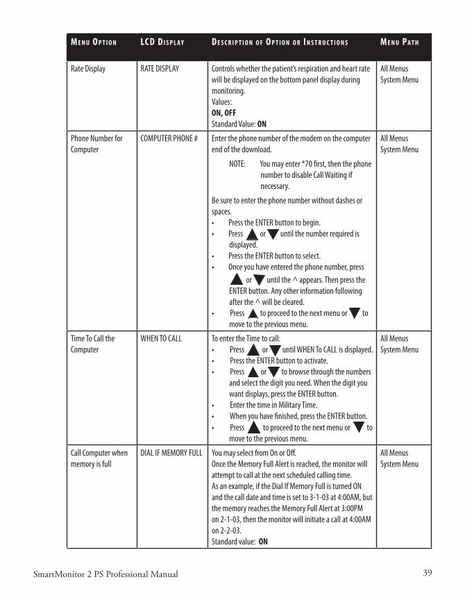
Rate Display RATE DISPLAY Controls whether the patient’s respiration and heart rate will be displayed on the bottom panel display during monitoring.Values:ON, OFFStandard Value: ON
All MenusSystem Menu
Phone Number for Computer
COMPUTER PHONE # Enter the phone number of the modem on the computer end of the download.
NOTE: You may enter *70 first, then the phone number to disable Call Waiting if necessary.
Be sure to enter the phone number without dashes or spaces.• Press the ENTER button to begin.• Press or until the number required is
displayed.• Press the ENTER button to select. • Once you have entered the phone number, press
or until the ^ appears. Then press the ENTER button. Any other information following after the ^ will be cleared.
• Press to proceed to the next menu or to move to the previous menu.
All MenusSystem Menu
Time To Call the Computer
WHEN TO CALL To enter the Time to call:• Press or until WHEN To CALL is displayed.• Press the ENTER button to activate.• Press or to browse through the numbers
and select the digit you need. When the digit you want displays, press the ENTER button.
• Enter the time in Military Time.• When you have finished, press the ENTER button.• Press to proceed to the next menu or to
move to the previous menu.
All MenusSystem Menu
Call Computer when memory is full
DIAL IF MEMORY FULL You may select from On or Off.Once the Memory Full Alert is reached, the monitor will attempt to call at the next scheduled calling time.As an example, if the Dial If Memory Full is turned ON and the call date and time is set to 3-1-03 at 4:00AM, but the memory reaches the Memory Full Alert at 3:00PM on 2-1-03, then the monitor will initiate a call at 4:00AM on 2-2-03.Standard value: ON
All MenusSystem Menu

40 SmartMonitor 2 PS Professional Manual
M e n u o p T I o n lCd d I s p l a y d e s C r I p T I o n o f o p T I o n o r I n s T r u C T I o n s M e n u pa T h
Move Data to Card MOVE DATA TO CARD?(other possible mes-sages)
Insert Card – Retry
Transferring Data…
Data Transferred
This menu is used to download the recorded data to the Memory Card. To move data to the Memory Card:• Press the ENTER button. The word NO will begin
to blink.• To select YES, press either arrow button.• Should a Memory Card not be inserted, the moni-
tor will ask for the card.• Place the card in the slot located just below the
display.• Press the ENTER button. • The display will now show “Transferring Data….”
Once the transfer is complete, the display will show “Data Transferred”.
All MenusSystem Menu
Memory Status MEMORY STATUS X PERCENT FULL
This is a display-only menu. It provides an indication of the amount of memory in use by the monitor. This display cannot be changed. The Memory Status setting takes into account the Patient Event Log, Equipment Event Log, and Waveform Memory.
All MenusSystem Menu
Clear Memory CLEAR MEMORY? Permits the memory to be erased. NOTE: Erasing memory does not affect the alarm and / or the record parameters, or the patient name and patient ID. • The memory should be cleared before using the
monitor on a new patient or after the data has been downloaded and saved.
• Once the memory is cleared the unit will display the following:
“It Is Cleared”.
All MenusSystem Menu
Afterthenewparametershavebeenenteredintothemonitor,itmustbeturnedofftoexitMenuMode.
TosettheparametersthroughtheSynergy-Ecomputersoftware,refertotheSynergy-E Manual for instructionsoncommunicatingwiththemonitor.
41SmartMonitor 2 PS Professional Manual
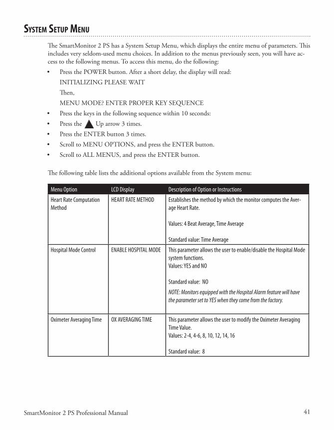
sysTeM seTup Menu
TheSmartMonitor2PShasaSystemSetupMenu,whichdisplaystheentiremenuofparameters.Thisincludesveryseldom-usedmenuchoices.Inadditiontothemenuspreviouslyseen,youwillhaveac-cesstothefollowingmenus.Toaccessthismenu,dothefollowing:• PressthePOWERbutton.Afterashortdelay,thedisplaywillread: INITIALIZINGPLEASEWAIT Then, MENUMODE?ENTERPROPERKEYSEQUENCE• Pressthekeysinthefollowingsequencewithin10seconds:• Pressthe Uparrow3times.• PresstheENTERbutton3times.• ScrolltoMENUOPTIONS,andpresstheENTERbutton.• ScrolltoALLMENUS,andpresstheENTERbutton.
The following table lists the additional options available from the System menu:
Menu Option LCD Display Description of Option or Instructions
Heart Rate Computation Method
HEART RATE METHOD Establishes the method by which the monitor computes the Aver-age Heart Rate.
Values: 4 Beat Average, Time Average
Standard value: Time Average
Hospital Mode Control ENABLE HOSPITAL MODE This parameter allows the user to enable/disable the Hospital Mode system functions. Values: YES and NO
Standard value: NO
NOTE: Monitors equipped with the Hospital Alarm feature will have the parameter set to YES when they come from the factory.
Oximeter Averaging Time OX AVERAGING TIME This parameter allows the user to modify the Oximeter Averaging Time Value. Values: 2-4, 4-6, 8, 10, 12, 14, 16
Standard value: 8

42 SmartMonitor 2 PS Professional Manual
Menu Option LCD Display Description of Option or Instructions
Alarm Hold-Off Delay Fol-lowing Probe Off
OX PROBE ON DELAY This parameter allows the user to modify the Alarm Hold-Off Delay Time after exiting a Probe Off condition. This parameter is factory set but can be adjusted to eliminate nuisance alarms. After a Probe Off condition, the Low SpO2 Alarm will be delayed for five seconds to allow the oximeter reading to stabilize.Values: 1, 2, 3, 4, 5, 6, 7, 8, 9, 10, 11, 12, 13, 14, 15, Off
Standard value: 5
Date Format Selection DATE FORMAT This parameter allows the user to display the date in either U.S. or international formats.
Values: MONTH/DAY/YEAR, DAY/MONTH/YEAR
Standard value: MONTH/DAY/YEAR
Memory Full Alert MEMORY FULL ALERT Two options are available: 80% full or 50% full. When the memory usage reaches the selected limit (50% or 80%), the unit will generate an alarm.
Standard value: 50%
Memory Full Audible MEMORY FULL AUDIBLE Used to enable/disable the audible alarm when the unit reaches the selected memory almost full limit (50%/80%). NOTE: This param-eter does not affect the visual indicator; it cannot be disabled.Values: ON, OFF
Standard Value: OFF
Modem Speed -Monitor MODEM SPEED-MONITOR The default setting is 38,400 BPS. This setting should not be changed unless directed to do so by Philips Children’s Medical Ventures Customer Service.
Modem Speed - Host MODEM SPEED – HOST The default setting is 115,500 BPS. This setting should not be changed unless directed to do so by Philips Children’s Medical Ventures Customer Service.
Embedded Software Revision
SOFTWARE REVISION Display-only menu. Displays the revision of the Embedded Applica-tion Code.
Maintenance Mode Software Revision
MMODE SW REVISION Display-only menu. Displays the revision of the Maintenance Mode Code.
Boot Block Software Revision
BBLK SW REVISION Display-only menu. Displays the revision of the Boot Block Code.
Oximeter Central Process-ing Unit Software Revision
OX CPU SW REVISION Display-only menu. Displays the revision of the Oximeter CPU Code.

43SmartMonitor 2 PS Professional Manual
Menu Option LCD Display Description of Option or Instructions
Oximeter Digital Signal Processor Software Revi-sion
OX DSP SW REVISION Display-only menu. Displays the revision of the Oximeter Digital Signal Processor Code.
Serial Number SERIAL NUMBER Display-only menu. Displays the Serial Number.
Language Selection SELECT A LANGUAGE Permits the selection of seven languages for displaying the LCD menus.
Standard value: ENGLIS
vIeW Menu Mode
Shouldtherebeaneed,themonitoralsoallowsyoutouseaViewOnlyoptionoftheMenuSelec-tions.• PressthePOWERbutton.Afterashortdelay,thedisplaywillread: INITIALIZINGPLEASEWAIT Then, MENUMODE?ENTERPROPERKEYSEQUENCE• Pressthefollowingkeysinthefollowingsequencewithin10seconds:• PresstheENTERbuttononce.• Usethe UpandDownarrowbuttonstoscrollthroughthemenus.
NOTE: The caregiver can download monitor data to a Memory Card using the View Menu but cannot make any changes to the settings in the monitor.
usIng auxIlIary equIpMenT
Therearefourauxiliarychannelsavailableonthemonitor.Thesechannelsprovidethemechanismforconnectingexternaldevicestothemonitor.AllExternalDevicesmustinterfacetothemonitorviatheAuxiliaryInterfaceBox,P/NH4010.Theoutputofthesedevicesmustbewithintherangeof–1.25to+1.25volts.
NOTE: Setup of auxiliary channels can be done only through the Synergy-E software. Refer to the Synergy-E Manual for more information.
TheSmartMonitor2PSisprogrammedwith15signaldefinitionstointerprettheauxiliarysignalsitreceives.Foreachofthefourauxiliarychannels,youcanchoosefromthelistof15.TheseareuserconfigurablewiththeSynergy-Esoftware.RefertotheSynergy-E Manual for more information on auxiliarysignalconfigurationforthemonitor.
Anyofthefoursignalscanbeprogrammedtorecordatonetime.TheAuxiliaryInterfaceBox(AIB)connectstotheI/OConnectionsport.• ConnecttheAIBtothebackofthemonitor.

44 SmartMonitor 2 PS Professional Manual
• Connecttheappropriateinterfacecabletothenumber1slotontheAIB.Theotherendofthecableshouldbeconnectedtotheauxiliarydevice.
NOTE: For every signal you want to record, you will need to connect an auxiliary cable to the AIB and remember to turn on the Auxiliary Channels in the monitor’s menu. For example, if you wish to record additional SpO2 and Pulse channels, you would need two auxiliary cables and this will use two auxiliary channels.
Informationrequiredtosetuporchangethe“definition”includesthedevicesvoltageandvaluerange.Thisinformationmustcomefromthemanufacturerofthedevice.
usIng nurse Call equIpMenT
WARNING: The Nurse Call feature of this device is for convenience only in hospital environment. The audible indica-tion provided by the Nurse Call system is not to be relied upon as the primary indication of the operating state of the device or of patient events.
WARNING: The Nurse Call feature should be considered a backup to the monitor’s primary alarm system. The opera-tor should not rely solely on the Nurse Call feature.
WARNING: Before making any connection to the rear-panel Nurse Call connector, the operator must verify that the equipment being connected does not exceed SELV (Safety Extra Low Voltage) levels as described in EN60601-1.
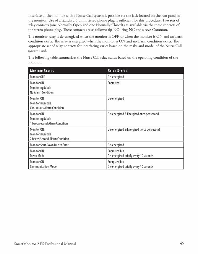
45SmartMonitor 2 PS Professional Manual
InterfaceofthemonitorwithaNurseCallsystemispossibleviathejacklocatedontherearpanelofthemonitor.Useofastandard3.5mmstereophoneplugissufficientforthisprocedure.Twosetsofrelaycontacts(oneNormallyOpenandoneNormallyClosed)areavailableviathethreecontactsofthestereophoneplug.Thesecontactsareasfollows:tip-NO,ring-NCandsleeve-Common.
Themonitorrelayisde-energizedwhenthemonitorisOFF,orwhenthemonitorisONandanalarmconditionexists.TherelayisenergizedwhenthemonitorisONandnoalarmconditionexists.TheappropriatesetofrelaycontactsforinterfacingvariesbasedonthemakeandmodeloftheNurseCallsystemused.
ThefollowingtablesummarizestheNurseCallrelaystatusbasedontheoperatingconditionofthemonitor:
M o n I T o r s T a T u s r e l a y s T a T u s
Monitor OFF De-energized
Monitor ONMonitoring ModeNo Alarm Condition
Energized
Monitor ONMonitoring ModeContinuous Alarm Condition
De-energized
Monitor ONMonitoring Mode1 beep/second Alarm Condition
De-energized & Energized once per second
Monitor ONMonitoring Mode2 beeps/second Alarm Condition
De-energized & Energized twice per second
Monitor Shut Down Due to Error De-energized
Monitor ONMenu Mode
Energized butDe-energized briefly every 10 seconds
Monitor ONCommunication Mode
Energized butDe-energized briefly every 10 seconds

46 SmartMonitor 2 PS Professional Manual

47SmartMonitor 2 PS Professional Manual
paTIenT seTup
Thissectionisanoverviewofthestepsyoushouldfollowtosetupthemonitorinthepatient’shome.Readtheentiremanualpriortorelyinguponthissection(alone)tosetupaSmartMonitor2PS.• EnsureMemoryhasbeenclearedpriortodeliverytonewpatient.• Reviewuseofthemonitoranditsaccessorieswiththecaregiver(s).BesuretoperformtheFunc-
tionalSelf-Test.Aself-testshouldbeperformedweeklyorwheneverleadwiresorECGpatientcablesarechanged.
• Stresstheimportanceofelectrodepositioning,beltsnugness,cleanelectrodes,andcleanskin.• Leaveyouremergencyphonenumber(s)andprocedureswiththecaregiver(s).
Step 1: Set the monitor on a Clean, Flat Surface.
• Besurethespeakerisnotblocked.• Toavoidinterference,besurethatnootherelectricalappliancesarewithinthreefeetofthemoni-
tor,patient,andpatientleads.• Makesurethemonitoriscloseenoughtoconnecttothepatientcomfortably.
WARNING: The monitor should not be placed in bed with the patient.
Step 2: Connect the ECG Patient Cable to the monitor.
• InserttheroundendoftheECGpatientcableintothebottomroundconnectorfoundonthefrontofthemonitor.
• Lineupthenotchontheconnectorandpushuntilyoufeeltheconnectorsnapintoplace.• ToremovetheECGpatientcable,graspitatthebaseofthepatientinputconnectorandgently
pullstraightback.Youshouldfeeltheoutersleeveslidebackandunlocktheconnectorasyoupull.
CAUTION: Do not twist or turn the ECG patient cable to remove from the monitor as this may cause damage to the ECG patient cable and/or monitor.
WARNING: The ECG patient cable should not be placed over the top of the crib rail. The cable should be placed between the vertical bars.

48 SmartMonitor 2 PS Professional Manual
Step 3: Connect the Lead Wires to the ECG Patient Cable.
ThelargerendoftheECGpatientcablehasthreeopenings,markedLA(black),RL(green),andRA(white).• TakethewhiteleadwireandinsertitintotheopeningmarkedRA.• TaketheblackleadwireandinsertitintotheopeningmarkedLA.• Firmlypusheachleadwireinuntilthesocketsnapsintoplace.
WARNING: When you need to remove a lead wire, grasp and pull at the strain relief area located near the connecting tip. Do not grasp the wire.
NOTE: Use of the third (green - RL) electrode and lead wire is normally not required but may help reduce excessive false low heart rate alarms.
Step 4: Connect the Lead Wires to the Electrodes.
• InserttheblackLAleadwireintooneelectrode.• InsertthewhiteRAleadwireintotheotherelectrode.• Makesurethemetaltipsoftheleadwiresarefullyinsertedintotheelectrodes.
NOTE: Refer to the section “Disposable Self-Adhesive Electrodes” if using this type of electrode.
NOTE: The 3M Red Dot ECG Electrode is compatible for use with the SmartMonitor 2 PS.
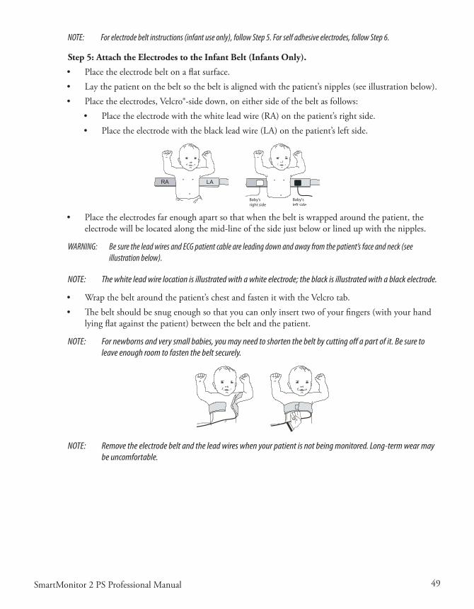
49SmartMonitor 2 PS Professional Manual
NOTE: For electrode belt instructions (infant use only), follow Step 5. For self adhesive electrodes, follow Step 6.
Step 5: Attach the Electrodes to the Infant Belt (Infants Only).
• Placetheelectrodebeltonaflatsurface.• Laythepatientonthebeltsothebeltisalignedwiththepatient’snipples(seeillustrationbelow).• Placetheelectrodes,Velcro®-sidedown,oneithersideofthebeltasfollows:
• Placetheelectrodewiththewhiteleadwire(RA)onthepatient’srightside.• Placetheelectrodewiththeblackleadwire(LA)onthepatient’sleftside.
Baby’sleft side
Baby’sright side
• Placetheelectrodesfarenoughapartsothatwhenthebeltiswrappedaroundthepatient,theelectrodewillbelocatedalongthemid-lineofthesidejustbeloworlinedupwiththenipples.
WARNING: Be sure the lead wires and ECG patient cable are leading down and away from the patient’s face and neck (see illustration below).
NOTE: The white lead wire location is illustrated with a white electrode; the black is illustrated with a black electrode.
• Wrapthebeltaroundthepatient’schestandfastenitwiththeVelcrotab.• Thebeltshouldbesnugenoughsothatyoucanonlyinserttwoofyourfingers(withyourhand
lyingflatagainstthepatient)betweenthebeltandthepatient.
NOTE: For newborns and very small babies, you may need to shorten the belt by cutting off a part of it. Be sure to leave enough room to fasten the belt securely.
NOTE: Remove the electrode belt and the lead wires when your patient is not being monitored. Long-term wear may be uncomfortable.
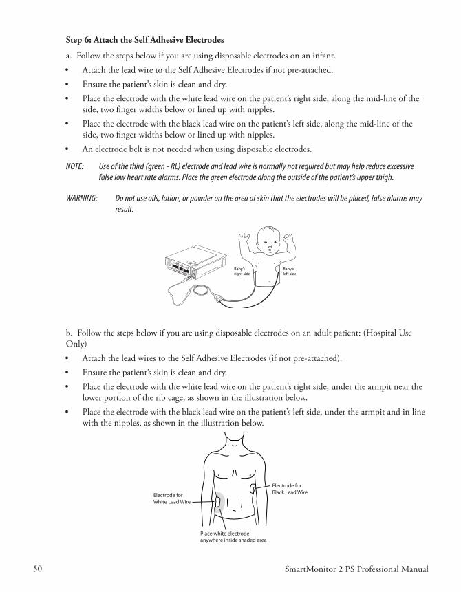
50 SmartMonitor 2 PS Professional Manual
Step 6: Attach the Self Adhesive Electrodes
a.Followthestepsbelowifyouareusingdisposableelectrodesonaninfant.• AttachtheleadwiretotheSelfAdhesiveElectrodesifnotpre-attached.• Ensurethepatient’sskiniscleananddry.• Placetheelectrodewiththewhiteleadwireonthepatient’srightside,alongthemid-lineofthe
side,twofingerwidthsbeloworlinedupwithnipples.• Placetheelectrodewiththeblackleadwireonthepatient’sleftside,alongthemid-lineofthe
side,twofingerwidthsbeloworlinedupwithnipples.• Anelectrodebeltisnotneededwhenusingdisposableelectrodes.
NOTE: Use of the third (green - RL) electrode and lead wire is normally not required but may help reduce excessive false low heart rate alarms. Place the green electrode along the outside of the patient’s upper thigh.
WARNING: Do not use oils, lotion, or powder on the area of skin that the electrodes will be placed, false alarms may result.
SpO2
%% Baby’s
right sideBaby’sleft side
b.Followthestepsbelowifyouareusingdisposableelectrodesonanadultpatient:(HospitalUseOnly)• AttachtheleadwirestotheSelfAdhesiveElectrodes(ifnotpre-attached).• Ensurethepatient’sskiniscleananddry.• Placetheelectrodewiththewhiteleadwireonthepatient’srightside,underthearmpitnearthe
lowerportionoftheribcage,asshownintheillustrationbelow.• Placetheelectrodewiththeblackleadwireonthepatient’sleftside,underthearmpitandinline
withthenipples,asshownintheillustrationbelow.
Electrode forWhite Lead Wire
Electrode forBlack Lead Wire
Place white electrodeanywhere inside shaded area
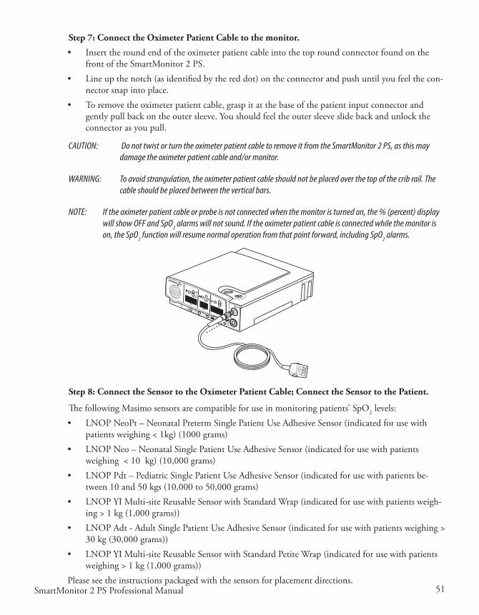
51SmartMonitor 2 PS Professional Manual
Step 7: Connect the Oximeter Patient Cable to the monitor.
• InserttheroundendoftheoximeterpatientcableintothetoproundconnectorfoundonthefrontoftheSmartMonitor2PS.
• Lineupthenotch(asidentifiedbythereddot)ontheconnectorandpushuntilyoufeelthecon-nectorsnapintoplace.
• Toremovetheoximeterpatientcable,graspitatthebaseofthepatientinputconnectorandgentlypullbackontheoutersleeve.Youshouldfeeltheoutersleeveslidebackandunlocktheconnectorasyoupull.
CAUTION: Do not twist or turn the oximeter patient cable to remove it from the SmartMonitor 2 PS, as this may damage the oximeter patient cable and/or monitor.
WARNING: To avoid strangulation, the oximeter patient cable should not be placed over the top of the crib rail. The cable should be placed between the vertical bars.
NOTE: If the oximeter patient cable or probe is not connected when the monitor is turned on, the % (percent) display will show OFF and SpO2 alarms will not sound. If the oximeter patient cable is connected while the monitor is on, the SpO2 function will resume normal operation from that point forward, including SpO2 alarms.
SpO2%%
Step 8: Connect the Sensor to the Oximeter Patient Cable; Connect the Sensor to the Patient.
ThefollowingMasimosensorsarecompatibleforuseinmonitoringpatients’SpO2 levels:• LNOPNeoPt–NeonatalPretermSinglePatientUseAdhesiveSensor(indicatedforusewith
patientsweighing<1kg)(1000grams)• LNOPNeo–NeonatalSinglePatientUseAdhesiveSensor(indicatedforusewithpatients
weighing<10kg)(10,000grams)• LNOPPdt–PediatricSinglePatientUseAdhesiveSensor(indicatedforusewithpatientsbe-
tween10and50kgs(10,000to50,000grams)• LNOPYIMulti-siteReusableSensorwithStandardWrap(indicatedforusewithpatientsweigh-
ing>1kg(1,000grams))• LNOPAdt-AdultSinglePatientUseAdhesiveSensor(indicatedforusewithpatientsweighing>
30kg(30,000grams))• LNOPYIMulti-siteReusableSensorwithStandardPetiteWrap(indicatedforusewithpatients
weighing>1kg(1,000grams))Pleaseseetheinstructionspackagedwiththesensorsforplacementdirections.
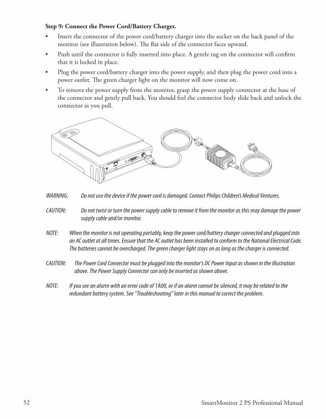
52 SmartMonitor 2 PS Professional Manual
Step 9: Connect the Power Cord/Battery Charger.
• Inserttheconnectorofthepowercord/batterychargerintothesocketonthebackpanelofthemonitor(seeillustrationbelow).Theflatsideoftheconnectorfacesupward.
• Pushuntiltheconnectorisfullyinsertedintoplace.Agentletugontheconnectorwillconfirmthatitislockedinplace.
• Plugthepowercord/batterychargerintothepowersupply,andthenplugthepowercordintoapoweroutlet.Thegreenchargerlightonthemonitorwillnowcomeon.
• Toremovethepowersupplyfromthemonitor,graspthepowersupplyconnectoratthebaseoftheconnectorandgentlypullback.Youshouldfeeltheconnectorbodyslidebackandunlocktheconnectorasyoupull.
WARNING: Do not use the device if the power cord is damaged. Contact Philips Children’s Medical Ventures.
CAUTION: Do not twist or turn the power supply cable to remove it from the monitor as this may damage the power supply cable and/or monitor.
NOTE: When the monitor is not operating portably, keep the power cord/battery charger connected and plugged into an AC outlet at all times. Ensure that the AC outlet has been installed to conform to the National Electrical Code. The batteries cannot be overcharged. The green charger light stays on as long as the charger is connected.
CAUTION: The Power Cord Connector must be plugged into the monitor’s DC Power Input as shown in the illustration above. The Power Supply Connector can only be inserted as shown above.
NOTE: If you see an alarm with an error code of 1A00, or if an alarm cannot be silenced, it may be related to the redundant battery system. See “Troubleshooting” later in this manual to correct the problem.

53SmartMonitor 2 PS Professional Manual
hospITal Mode
Themonitor’sHospitalModeControlparameterissettoNOwhenitcomesfromthefactory.ThiscontrolenablesthefeaturesofHospitalMode,specifically:• eliminationofthesiblingprotectionmechanism• silencealarmfeatureforpatientalarms• alarmsetpointreviewatpoweron.
Tomakechangestothisparameter,refertothesection“SystemSetupMenu”earlierinthismanual.
Ifthemonitorisgoingtobeusedinahomesetting,makesurethattheHospitalModeControlparameterissettoNO.
NOTE: Monitors equipped with the Hospital Alarm feature will have the parameter set to YES when they come from the factory.

54 SmartMonitor 2 PS Professional Manual

55SmartMonitor 2 PS Professional Manual
respondIng To alarMs
paTIenT alarM
APatientAlarmindicatesthatthepatient’sbreathing,heartactivityoroxygensaturationisoutsidethelimitsprescribedbythephysician.Theinformationinthissectioncanhelpyourespondappropriatelytopatientalarms.Readthissectioncarefully.Ifyouhaveanyquestions,pleasecontactPhilipsChil-dren’sMedicalVentures.
TesTIng The alarM
Beforeyouusethemonitor,testtodetermineifyoucanhearthealarmfromdifferentroomswhilethereisnoiseinthehouse.
CAUTION: Be aware that the alarm sound is very loud. Do not place the monitor in the bed with the patient or direct the speaker toward the patient.
• Alwayskeeptheareainfrontofthespeakerclear.• Turnthemonitoron(withoutthepatientattached)tosoundthealarm.Makesureyoucanhear
thealarmindifferentareasinthehome.
SpO 2
%%
Speaker
NOTE: The monitor contains multiple buzzers and alarm sounds. If a buzzer/alarm sound changes or no longer func-tions, contact your home care provider immediately.

56 SmartMonitor 2 PS Professional Manual
If an alarM sounds
Ifanalarmsoundswhilethepatientisbeingmonitored,checkthepatientfirst.Thenfollowtheinstructionsbelowtorespondtolightsandalarms.Alwayscheckthepatient’sskincolor.Isitnormal?Alwayschecktodetermineifthepatientisbreathing.Ifthepatientisnotbreathing,interveneandprovidestimulationasyouhavebeeninstructed.
l I g h T a l a r M C h e C k pa T I e n T ’s C o n d I T I o n r e s p o n d l I k e T h I s
Red Apnea and/or Low (Heart)
Intermittent (1 beep/sec.)
Skin color is pale or blue. Patient is not breathing or is choking.
Respond as instructed by the physician or in your CPR class. • Gently pat the patient. The patient may start
breathing and correct the cause of the alarm on his/her own.
• If the patient does not start breathing, start physical stimulation immediately.
• If the patient starts breathing and corrects the cause of the alarm, note it on your log sheet.
• Press the RESET button to reset any alarm lights.
Red Apnea and/or Low (Heart
or SpO2 )
Intermittent (1 beep/sec.)
Patient is breathing and is responsive. Color is good.
• Wait for a few seconds. Watch to see if the patient’s breathing and color remain normal.
• If the alarm continues, see the section “Reducing False Alarms.”
• Check the monitor to see which light is on. Note it on your log sheet.
• Check the sensors.
Red High (Heart) Intermittent (2 beeps/sec.)
Patient is crying. • If the patient has frequent high heart rate alarms not associated with crying, please notify the physician.
• Calm the patient.• Check the monitor to see which light is on.
Note the light on your log sheet.

57SmartMonitor 2 PS Professional Manual
l I g h T a l a r M C h e C k pa T I e n T ’s C o n d I T I o n r e s p o n d l I k e T h I s
Red Low SpO2 Intermittent (1 beep/sec.)
Skin color is pale or blue. Patient is not breathing or choking.
Skin color is pale or blue. Patient is breathing.
If patient is receiving supplemen-tal oxygen.\
Skin color is pink, patient is breath-ing.
• Use the response under apnea/low heart rate above.
• Observe the patient closely and respond as instructed by the physician or in your CPR class. If the condition does not improve, notify the physician or EMS.
• Check the oxygen cannula and oxygen delivery device. Increase oxygen as ordered by physician.
• Notify physician or EMS immediately if condi-tion does not improve or recurs frequently. Record alarm on log sheet.
• Wait a few seconds. Watch to determine if the patient’s breathing and color remains normal. If alarm continues, see the section “Reducing False Alarms.” Check sensors.
Red High SpO2 Intermittent(2 beeps/sec.)
Skin color is pink, patient breath-ing.
• Note alarm on the log sheet and report to the physician as instructed.
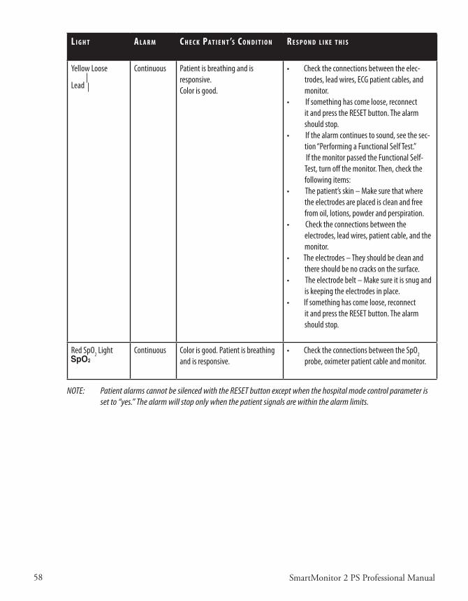
58 SmartMonitor 2 PS Professional Manual
l I g h T a l a r M C h e C k pa T I e n T ’s C o n d I T I o n r e s p o n d l I k e T h I s
Yellow Loose
Lead
Continuous Patient is breathing and is responsive.Color is good.
• Check the connections between the elec-trodes, lead wires, ECG patient cables, and monitor.
• If something has come loose, reconnect it and press the RESET button. The alarm should stop.
• If the alarm continues to sound, see the sec-tion “Performing a Functional Self Test.”
If the monitor passed the Functional Self-Test, turn off the monitor. Then, check the following items:
• The patient’s skin – Make sure that where the electrodes are placed is clean and free from oil, lotions, powder and perspiration.
• Check the connections between the electrodes, lead wires, patient cable, and the monitor.
• The electrodes – They should be clean and there should be no cracks on the surface.
• The electrode belt – Make sure it is snug and is keeping the electrodes in place.
• If something has come loose, reconnect it and press the RESET button. The alarm should stop.
Red SpO2 Light Continuous Color is good. Patient is breathing and is responsive.
• Check the connections between the SpO2 probe, oximeter patient cable and monitor.
NOTE: Patient alarms cannot be silenced with the RESET button except when the hospital mode control parameter is set to “yes.” The alarm will stop only when the patient signals are within the alarm limits.

59SmartMonitor 2 PS Professional Manual
respondIng To sysTeM alarMs
ASystemAlarmindicatesthatthemonitormaynotbefunctioningproperlyoratoptimumcapacity.Theinformationinthissectionwillhelpyourespondappropriatelytosystemalarms.Whenasystemalarmoccurs,oneofthelightsatthebottomofthefrontpanelwillcomeon.
I f T h I s l I g h T I s o n a n d T h I s C o n d I T I o n e x I s T s I T M e a n s.. .
Power Continuous green light, no alarm. Normal Operation. The green power indicator light will come on and stay on for as long as the monitor is on.
Charger Continuous or blinking green light, no alarm.
Normal Operation. The green charger light will come on and blink when the battery is charging and stay on when the battery is fully charged while the battery charger is plugged into an active outlet and connected to the monitor.
Low Battery Flashing yellow light, continuous alarm.
Continuous yellow light, continuous alarm.
This is a warning that the battery voltage is very low and should be recharged soon. (See the section “Charging the Monitor’s Battery” later in this manual.) Press the RESET button to temporarily silence the alarm. The alarm will resound in 2 minutes if the monitor has not been plugged in. The yellow light will continue to flash.
This is a warning that the battery is too low for the moni-tor to operate properly. The monitor must be recharged. Turn the monitor off. Then, recharge the battery. (See “Charging the Battery” in this manual).If you do not recharge the battery, the system will auto-matically shut down.
Memory Full Flashing yellow light, continuous alarm.
Flashing yellow light, no alarm.
When the monitor’s Memory Almost full parameter is reached, the Memory Full light will flash. The alarm will sound continuously. The alarm will sound only if the monitor has been programmed to do so at the 50% full or at 80% full. Press the RESET button to silence the alarm. The light will blink every second.
NOTE: Memory Full is a warning condition. You can continue monitoring. However, you should download the memory to resolve the alarm.NOTE: The Memory Full alarm will sound each time the monitor is powered on.

60 SmartMonitor 2 PS Professional Manual
I f T h I s l I g h T I s o n a n d T h I s C o n d I T I o n e x I s T s I T M e a n s.. .
Memory Full Continuous yellow light, continuous alarm.Continuous yellow light, no alarm.
The monitor’s memory is 100% full. Press the RESET but-ton to silence the alarm. The light will stay on continu-ously. You must transfer data when you get a memory 100% full condition. (See “Transferring SmartMonitor 2 PS Memory” in this manual for more information.)NOTE: The alarm will sound only if the monitor has been programmed to do so.
Loose Lead Continuous yellow light and continuous alarm
The yellow loose lead light and the alarm may sound continuously when there is a problem with any of the following:• Lead wires• Electrodes• Electrode belt• ECG Patient cable, or• Connections between the patient’s skin and the electrodes, the lead wires, the patient cable(s), and the monitor.
Loose Lead Continuous yellow light and no alarm If you correct the problem, the alarm will stop. However,
the yellow light remains on until you press the RESET button.
Power Continuous green light, continuous alarm, with no other lights lit.
Check the bottom panel display for error messages. If no error messages are displayed, the monitor was turned off improperly causing a sibling alarm.To resolve:Press and hold the blue RESET button.Press and release the gray POWER button.Wait two seconds then release the RESET button.
All All lights are blinking and the alarm will come on for three seconds and then off for one second.
Check the bottom LCD display for error messages. If there is an error message, enter it on your log sheet.Turn the monitor off and then back on. If the monitor functions normally continue to use the monitor. If not contact Philips Children’s Medical Ventures for service.
SpO2 Continuous red light and continuous alarm (if enabled)
Check that the SpO2 probe has not become dislodged from the patient or that the probe has not been discon-nected from the monitor or oximeter patient cable. If you correct the problem, the alarm will stop. However, the red light remains on until you press the RESET button.
NOTE: When the Hospital Mode Control parameter is set to YES, the Silence Alarm feature is enabled. This allows the user to silence the audible alarm for 60 seconds when the alarm is being caused by a physiologic event(s). The user can silence the alarm by pressing the RESET button. If the physiologic event(s) is still active after 60 second(s), the alarm will sound again. This feature only affects the audible portion of the alarm. The front panel indicators are not affected.

61SmartMonitor 2 PS Professional Manual
reduCIng false alarMs
Properelectrodeplacementwillminimizefalsealarms.• Makesuretheelectrodesareplacedalongthemid-lineoftheside,twofingerwidthsbelowor
linedupwiththenipples.• IfusingtheblackreusableelectrodeswiththeVelcrobelt,ensurethebeltisquitesnug.Placethe
electrodes far enough apart so that when the belt is wrapped around the patient, the electrode will belocatedalongthemid-lineoftheside,twofingerwidthsbeloworlinedupwiththenipples.
• Theskinshouldbecleananddry.Iftheskinisunusuallydry,youmayaddafewdropsofmois-ture(water)tothepatient’sskinpriortoelectrodebeltplacement.
• Whenusingtheblackreusableelectrodes,ensurethattheelectrodesurfaceisclean.• Useofthethird(green-RL)electrodeandleadwireisnormallynotrequired,butmayhelp
reduceexcessivefalselowheartratealarms.Placethegreenelectrodealongtheoutsideofpatient’supperthigh.
• CheckforcorrectplacementoftheSpO2(oxygen)sensor.• VerifythattheappropriateSpO2(oxygen)sensorisusedforthepatient’sweight.
NOTE: Refer to the Synergy-E Manual for more information on how to check signal quality using a modem or using a direct-connect cable.

62 SmartMonitor 2 PS Professional Manual
63SmartMonitor 2 PS Professional Manual
MonITorIng
TurnIng The MonITor on
Afteryouhaveproperlysetupthemonitor,andlearnedhowthemonitorfunctionsandhowtorespondtoalarms,youcanbeginmonitoringthepatient’sbreathing,heartactivityandSpO2 level ac-cordingtothescheduleprescribedbythephysician.
PushthePOWERbutton.Themonitorperformsasystemcheck.Thelightsonthefrontofthemonitorwillcomeonbrieflyandtheaudiblealarmwillbeeptwice.Within10seconds,thegreenrespiration, heart, and SpO2 lightswillbegintoblink.Ifthelightsdonotblink,checkthatyouhaveattached the electrode belt or electrodes properly to the patient, the lead wires are pushed in, and that cablesareconnected.Oncethepatientisproperlyconnectedtothemonitorandthepowerison,thefollowing should occur:• Thegreen(battery)chargerlightison(ifthemonitorispluggedintoanACoutlet).• Thegreenpowerlightison.• Thegreenrespirationlight,greenheartlight,andgreenSpO2lightareblinking.• Allotherlightsshouldbeoff.• Ifthelightsdonotblink,refertothestepsfoundin“HomeSetup”earlierinthismanual.Besure
youhavefollowedallinstructions.
NOTE: If the Hospital Mode Control and front panel parameter are set to YES, then each of the following will appear briefly on the front panel display during startup:
• Afterallthelightshaveturnedonandtheaudiblealarmhassoundedbriefly,theApneaAlarmLEDwilllightupandvalueoftheApneaSystemparameterwillappearaboveBrPMonthefrontpaneldisplay.
• TheBradycardia(lowheartrate)AlarmLEDwilllightupandthevalueoftheBradycardiaSys-temParameterwillappearaboveBPMonthefrontpaneldisplay.
• TheTachycardia(highheartrate)AlarmLEDwilllightupandthevalueoftheTachycardiaSys-temParameterwillappearaboveBPMonthefrontpaneldisplay.
• TheLowSpO2AlarmLEDwilllightupandthevalueoftheLowSpO2 System Parameter will appear above SpO2onthefrontpaneldisplay.
• TheHighSpO2AlarmLEDwilllightupandthevalueoftheHighSpO2 System Parameter will appear above SpO2onthefrontpaneldisplay.
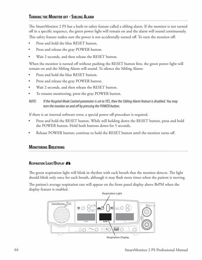
64 SmartMonitor 2 PS Professional Manual
TurnIng The MonITor off - sIblIng alarM
TheSmartMonitor2PShasabuilt-insafetyfeaturecalledasiblingalarm.Ifthemonitorisnotturnedoffinaspecificsequence,thegreenpowerlightwillremainonandthealarmwillsoundcontinuously.Thissafetyfeaturemakessurethepowerisnotaccidentallyturnedoff.Toturnthemonitoroff:• PressandholdtheblueRESETbutton.• PressandreleasethegrayPOWERbutton.
• Wait2seconds,andthenreleasetheRESETbutton.
WhenthemonitoristurnedoffwithoutpushingtheRESETbuttonfirst,thegreenpowerlightwillremainonandtheSiblingAlarmwillsound.TosilencetheSiblingAlarm:• PressandholdtheblueRESETbutton.• PressandreleasethegrayPOWERbutton.• Wait2seconds,andthenreleasetheRESETbutton.• Toresumemonitoring,pressthegrayPOWERbutton.
NOTE: If the Hospital Mode Control parameter is set to YES, then the Sibling Alarm feature is disabled. You may turn the monitor on and off by pressing the POWER button.
Ifthereisaninternalsoftwareerror,aspecialpoweroffprocedureisrequired.• PressandholdtheRESETbutton.WhilestillholdingdowntheRESETbutton,pressandhold
thePOWERbutton.Holdbothbuttonsdownfor5seconds.
• ReleasePOWERbutton;continuetoholdtheRESETbuttonuntilthemonitorturnsoff.
MonITorIng breaThIng
respIraTIon lIghT/dIsplay
Thegreenrespirationlightwillblinkinrhythmwitheachbreaththatthemonitordetects.Thelightshouldblinkonlyonceforeachbreath,althoughitmayflashmoretimeswhenthepatientismoving.
Thepatient’saveragerespirationratewillappearonthefrontpaneldisplayaboveBrPMwhenthedisplayfeatureisenabled.
SpO 2
%%
Respiration Display
Respiration Light
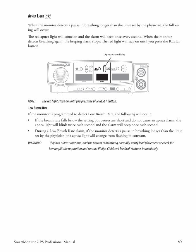
65SmartMonitor 2 PS Professional Manual
apnea lIghT
When the monitor detects a pause in breathing longer than the limit set by the physician, the follow-ingwilloccur.
Theredapnealightwillcomeonandthealarmwillbeeponceeverysecond.Whenthemonitordetectsbreathingagain,thebeepingalarmstops.TheredlightwillstayonuntilyoupresstheRESETbutton.
SpO 2
%%
Apnea Alarm Light
NOTE: The red light stays on until you press the blue RESET button.
loW breaTh raTe
IfthemonitorisprogrammedtodetectLowBreathRate,thefollowingwilloccur:• Ifthebreathratefallsbelowthesettingbutpausesareshortanddonotcauseanapneaalarm,the
apnealightwillblinktwiceeachsecondandthealarmwillbeeponceeachsecond.• DuringaLowBreathRatealarm,ifthemonitordetectsapauseinbreathinglongerthanthelimit
setbythephysician,theapnealightwillchangefromflashingtoconstant.
WARNING: If apnea alarms continue, and the patient is breathing normally, verify lead placement or check for low amplitude respiration and contact Philips Children’s Medical Ventures immediately.
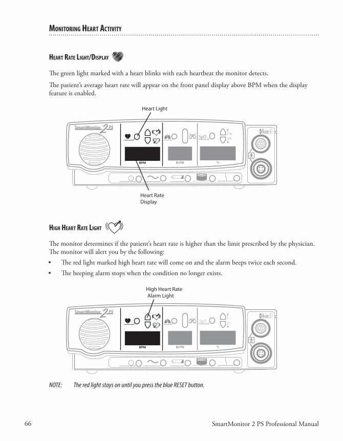
66 SmartMonitor 2 PS Professional Manual
MonITorIng hearT aCTIvITy
hearT raTe lIghT/dIsplay
Thegreenlightmarkedwithaheartblinkswitheachheartbeatthemonitordetects.
Thepatient’saverageheartratewillappearonthefrontpaneldisplayaboveBPMwhenthedisplayfeatureisenabled.
SpO 2
%%
Heart Light
Heart Rate Display
hIgh hearT raTe lIghT
Themonitordeterminesifthepatient’sheartrateishigherthanthelimitprescribedbythephysician.The monitor will alert you by the following:• Theredlightmarkedhighheartratewillcomeonandthealarmbeepstwiceeachsecond.• Thebeepingalarmstopswhentheconditionnolongerexists.
SpO 2
%%
High Heart RateAlarm Light
NOTE: The red light stays on until you press the blue RESET button.
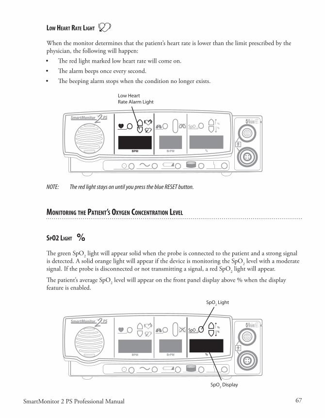
67SmartMonitor 2 PS Professional Manual
loW hearT raTe lIghT
Whenthemonitordeterminesthatthepatient’sheartrateislowerthanthelimitprescribedbythephysician, the following will happen:• Theredlightmarkedlowheartratewillcomeon.• Thealarmbeepsonceeverysecond.• Thebeepingalarmstopswhentheconditionnolongerexists.
SpO 2
%%
Low HeartRate Alarm Light
NOTE: The red light stays on until you press the blue RESET button.
MonITorIng The paTIenT’s oxygen ConCenTraTIon level
spo2 lIghT
The green SpO2 light will appear solid when the probe is connected to the patient and a strong signal isdetected.AsolidorangelightwillappearifthedeviceismonitoringtheSpO2 level with a moderate signal.Iftheprobeisdisconnectedornottransmittingasignal,aredSpO2lightwillappear.
Thepatient’saverageSpO2levelwillappearonthefrontpaneldisplayabove%whenthedisplayfeatureisenabled.
SpO 2
%%
SpO2 Light
SpO2 Display

68 SmartMonitor 2 PS Professional Manual
hIgh spo2 alarM lIghT
Whenthemonitordeterminesthatthepatient’sSpO2 level is higher than the limit set by the physi-cian, the following will happen:• TheredlightmarkedHighSpO2AlarmLightwillcomeon,andthealarmwillbeeptwiceeach
second.• Thebeepingalarmstopswhentheconditionnolongerexists.
SpO 2
%%
High SpO2Alarm Light
NOTE: The red light stays on until you press the blue RESET button.
loW spo2 alarM lIghT
Whenthemonitordeterminesthatthepatient’sSpO2 level is lower than the limit set by the physician, the following will happen:• TheredlightmarkedLowSpO2AlarmLightwillcomeon,andthealarmwillbeeponceeach
second.• Thebeepingalarmstopswhentheconditionnolongerexists.
SpO 2
%%
Low SpO2Alarm Light
NOTE: The red light stays on until you press the blue RESET button.

69SmartMonitor 2 PS Professional Manual
porTable operaTIon of The sMarTMonITor 2 psThemonitorisdesignedforportableuse.Whenthepowercordisnotused,themonitorreliesonapreviouslychargedinternalbatteryforpower.
PhilipsChildren’sMedicalVenturesrecommendsthatthemonitorbeusedwiththepowercord/bat-terychargerwheneverpossible.However,whenthemonitorisusedwithoutthepowercord/batterychargerthemonitorisfullyfunctional.Allalarmsareoperational.Withafullychargedbattery,themonitorwillrunfor15hourswiththeoximeteroff.Pleasenotethatthefrontpaneldisplay(ifen-abled) will be dimmed to conserve battery life, and you will not be able to adjust the brightness in this mode.Theamountoftimetocompletelyrechargeafullydepletedbatteryis8hours.
SmartMonitor2PSincludesaredundantbatterysystem.ArechargeablebatterypackandtwoAAAalkalinebatteriesarelocatedinthebatterycompartment.Ifthereisafailureintherechargeablepack,theAAAbatteriesgenerateanalarm.Iftherechargeablepackisnearlycompletelydischarged,thealarmwillalsosound.Thismayoccurwhenthebatterypackisfirstinstalledinanewmonitororifamonitorisunusedfortwomonthsorlonger.Alwaysunplugthebatterypackcableisyouarenotgo-ingtousethemonitorforanextendedperiodoftime.Thispreventsunnecessaryalarmsuponfuturereconnection.
ChargIng The MonITor’s baTTery
Asarule,afullychargedbatterycanoperatefor15hourswiththeoximeteroff.Thismayvary,how-ever,dependingonthelevelofuse,numberofalarms,andotherfactors.Whenthelowbatterylightcomeson,youshouldrechargethebatteryimmediately.Afullydrainedbatteryshouldberechargedfor8hours.Whenyouneedtorechargethemonitor’sbattery,followthestepsbelow.• Inserttheconnectorofthepowersupplyintothesocketonthebackpanelofthemonitor.(See
illustrationbelow.)Theflatsideoftheconnectorfacesupward.• Pushuntiltheconnectorisfullyinsertedintoplace.Agentletugontheconnectorwillconfirm
thatitislockedinplace.• Plugthepowercord/batteryintoapoweroutlet.• Thegreenchargerlightcomesonsolidifthebatteryisfullychargedorblinkswhenthebatteryis
charging.• Ifthemonitoristurnedon,theyellowlowbatterylightblinksuntiltheminimumchargelevelis
reached.Then,theyellowlightgoesoff• Toremovethepowersupplyfromthemonitor,graspthepowersupplyconnectoratthebaseof
theconnectorandgentlypullback.Youshouldfeeltheconnectorbodyslidebackandunlocktheconnectorasyoupull.

70 SmartMonitor 2 PS Professional Manual
NOTE: Fully drained batteries need about 8 hours to recharge.
sMarTMonITor 2 ps baTTery paCk
Warnings
• Neverchangethebatterypackwhilethepowersupplyispluggedinand/orthemonitorisbeingoperated.
• Donotdisassemblethebatterypackorbatteries.Thebatteriescontainelectrolytes,whichcancauseinjurytoeyes,skin,andclothing.
• Donotdisposeoftheoldbatteryinfireorincinerator.Thebatterypackcontainsingredientsthatcouldbeexplosiveandcauseseriouspersonalinjury.
• Donotdisassembleormodifythebattery.Thebatterycontainssafetyandprotectiondevicesthat,ifdamaged,maycausethebatterytoheat,rupture,orignite.
Cautions
• Thebatterypackhasalockingconnector.Donotattempttoremovethebatterypackwithoutreleasingthelatchontheconnector.Doingsowilldamagethebatterywires.
• UseonlyPhilipsChildren’sMedicalVentures-suppliedbatterypacks.Useofotherbatterypackscouldcausemalfunction.
• Whenthebatteryiswornout,insulatetheterminalswithadhesivetapeorsimilarmaterialsbeforedisposal.
baTTery InsTallaTIon InsTruCTIons
Themonitorusestwotypesofbatteries.Rechargeablebatteriesareusedforpowerduringportableoperation.Alkalinebatteriesprovideaback-upalarmfunctioniftherechargeablebatteriesfail.Therechargeablebatteriesarecontainedinsideabatterypack.Twoalkaline,sizeAAA,batteriesareplacedintoaAAAholderlocatedonthesideoftherechargeablepack.
NOTE: Before installing a new or replacement battery pack, write the installation date on the label provided on the battery pack.
1. Turnthemonitors’poweroffusingthecorrectPower-offprocedure,andunplugtheexternalpowersupplyfromthemonitor.
2. Loosen(counterclock-wise)bothscrewsfromthebatterypackcoverandremovethecover.
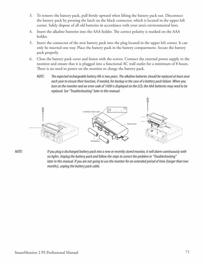
71SmartMonitor 2 PS Professional Manual
3. Toremovethebatterypack,pullfirmlyupwardwhenliftingthebatterypackout.Disconnectthe battery pack by pressing the latch on the black connector, which is located in the upper left corner.Safelydisposeofalloldbatteriesinaccordancewithyourarea’senvironmentallaws.
4. InsertthealkalinebatteriesintotheAAAholder.ThecorrectpolarityismarkedontheAAAholder.
5. Inserttheconnectorofthenewbatterypackintothepluglocatedintheupperleftcorner.Itcanonlybeinsertedoneway.Placethebatterypackinthebatterycompartment.Securethebatterypackproperly.
6. Closethebatterypackcoverandfastenwiththescrews.ConnecttheexternalpowersupplytothemonitorandensurethatitispluggedintoafunctionalACwalloutletforaminimumof8hours.Thereisnoneedtopoweronthemonitortochargethebatterypack.
NOTE: The expected rechargeable battery life is two years. The alkaline batteries should be replaced at least once each year to ensure their function, if needed, for backup in the case of a battery pack failure. When you turn on the monitor and an error code of 1A00 is displayed on the LCD, the AAA batteries may need to be replaced. See “Troubleshooting” later in this manual.
Battery Pack Cover
Battery Pack
AA Batteries
Installation Date Label
Cover
Battery
NOTE: If you plug a discharged battery pack into a new or recently stored monitor, it will alarm continuously with no lights. Unplug the battery pack and follow the steps to correct the problem in “Troubleshooting” later in this manual. If you are not going to use the monitor for an extended period of time (longer than two months), unplug the battery pack cable.

72 SmartMonitor 2 PS Professional Manual

73SmartMonitor 2 PS Professional Manual
TransferrIng sMarTMonITor 2 ps InforMaTIon
The monitor contains a memory system that automatically records information about each monitor-ingsession.Thisinformationcanbetransferred(ordownloaded)toacomputertobereviewedbythephysician.Thereareseveraldifferentwaystotransferthisinformation.
Whatevermethodyouuse,youmusttransferdatawhenyougetamemory100%fullcondition.Ad-ditionally, you may choose to transfer data at any time or whenever it is considered necessary by the physician.
MeMory ManageMenT In The MonITor
WhendataissuccessfullytransferredtoaMemoryCardordownloadedtoSynergy-E,thedataap-pearstobeerasedinthemonitor.Itnolongercountstowardthereadingof“PercentMemoryFull”ontheLCDorinSynergy-E.Becauseofthismemorymanagementsystem,itisnotnecessarytoerasethememoryaftereverydownload.ShouldadatafilebecomecorruptedorlostonthePCrunningSynergy-E,thedatamaystillberecoveredfromthemonitor.ThedatacanberecoveredusingSynergy-Euntilthemonitorhascollectednewdataandneedsthespaceoccupiedbytheolddata.
Itisrecommendedthatyouerasethememorybetweeneachpatientuse.Pleasenotethatthisfeaturewillnotclearthesystemparametersettings(alarmandrecordlimits)orthepatientnameandIDnumber.
Usingthe“ClearMemory”functionintheSystemParametersmenuswillerasealldataregardlessofwhetherornotithasbeendownloaded.
To reCover The old daTa usIng a MeMory Card
Transferthedatatothecardusingthemonitor.NowimportthecardintoSynergy-E.Whenprompt-edwith“Onlyobtaindatanotpreviouslyretrieved?”,answerNOtoobtainalldata.Synergy-Ewillthendisplayallthedatathatwasinthemonitor.
To reCover The old daTa by doWnloadIng usIng synergy-e
CleartheCheckboxinthemonitorcommunicationsscreenwhichreads,“Onlyretrievedatanotpre-viouslydownloaded?”.Synergy-Ewillthendisplayallthedatathatwasinthemonitor.
ModeM doWnload
NOTE: The monitor must be plugged into the electrical outlet during modem downloads.
Therearethreewaystodownloadwithamodem.Thefirstchoiceinvolvesthemodemautomaticallycallingthehomecaredealer.ThisiscalledModemAutoDial.Thisdoesn’tinvolveanyactiononthecaregivers’part.Itisimportanttoknowthatthemodeminsidetheunitmayusethephoneline.Ifyouaregoingtousethisfeature,youshouldgivemorespecificinstructionstothecaregiver.
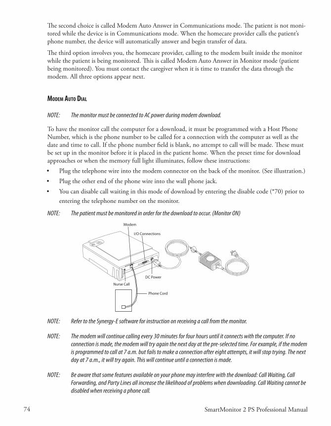
74 SmartMonitor 2 PS Professional Manual
ThesecondchoiceiscalledModemAutoAnswerinCommunicationsmode.Thepatientisnotmoni-toredwhilethedeviceisinCommunicationsmode.Whenthehomecareprovidercallsthepatient’sphonenumber,thedevicewillautomaticallyanswerandbegintransferofdata.
The third option involves you, the homecare provider, calling to the modem built inside the monitor whilethepatientisbeingmonitored.ThisiscalledModemAutoAnswerinMonitormode(patientbeingmonitored).Youmustcontactthecaregiverwhenitistimetotransferthedatathroughthemodem.Allthreeoptionsappearnext.
ModeM auTo dIal
NOTE: The monitor must be connected to AC power during modem download.
Tohavethemonitorcallthecomputerforadownload,itmustbeprogrammedwithaHostPhoneNumber,whichisthephonenumbertobecalledforaconnectionwiththecomputeraswellasthedateandtimetocall.Ifthephonenumberfieldisblank,noattempttocallwillbemade.Thesemustbesetupinthemonitorbeforeitisplacedinthepatienthome.Whenthepresettimefordownloadapproaches or when the memory full light illuminates, follow these instructions: • Plugthetelephonewireintothemodemconnectoronthebackofthemonitor.(Seeillustration.)• Plugtheotherendofthephonewireintothewallphonejack.• Youcandisablecallwaitinginthismodeofdownloadbyenteringthedisablecode(*70)priorto
enteringthetelephonenumberonthemonitor.
NOTE: The patient must be monitored in order for the download to occur. (Monitor ON)
Phone Cord
Modem
I/O Connections
DC Power
Nurse Call
NOTE: Refer to the Synergy-E software for instruction on receiving a call from the monitor.
NOTE: The modem will continue calling every 30 minutes for four hours until it connects with the computer. If no connection is made, the modem will try again the next day at the pre-selected time. For example, if the modem is programmed to call at 7 a.m. but fails to make a connection after eight attempts, it will stop trying. The next day at 7 a.m., it will try again. This will continue until a connection is made.
NOTE: Be aware that some features available on your phone may interfere with the download: Call Waiting, Call Forwarding, and Party Lines all increase the likelihood of problems when downloading. Call Waiting cannot be disabled when receiving a phone call.

75SmartMonitor 2 PS Professional Manual
WARNING: If there is an emergency and access to the telephone is required while the modem is in use, remove the phone cord from the modem slot and use a working phone.
ModeM auTo ansWer In CoMMunICaTIons Mode
ThemonitormustbeconnectedtoACpowerduringmodemdownload.1. Connectaphonecordfromthewalljacktothemodemconnectoronthebackofthemonitor.2. Toallowthemonitortoworkwiththemodem,placethemonitorinCommunicationsMode:
• PressandreleasethePOWERbuttontoturnthemonitoron.• PressandholdtheblueRESETbutton.• Waituntilthemonitoralarms.• ReleasetheRESETbutton.BrieflypressandreleasetheRESETbuttonagain.Themonitor’s
bottomdisplaywillread“CommunicationModeisNowActive.”
Themonitorbeepsevery10secondswheneveritisintheCommunicationsMode.Thisisareminderthatthemonitorispoweredonforworkingwiththecomputer,MemoryCard,ormo-dem,butnotformonitoringthepatient.
DonotconnectthepatienttothemonitorwhenintheCommunicationsMode;theapneaandheartratealarmsarenotoperationalinthismode.• Thehomecareprovidershouldnowcalltoretrievetheinformation.Thephonemayring,
butdonotanswer.Themodemanswersthecallandconnectsthemonitortothecomputerthroughthephoneline.
3. Theamountoftimetotransfertheinformationwillvary.Whenthetransferiscompletethemonitorwillbeepfivetimes.Afterthetransfer,youmaydisconnectthephonelinefromthemonitorandthephonewillworknormally.Turnthemonitoroffinthenormalway.• PressandholdtheblueRESETbutton.• PressandreleasethegrayPOWERbutton.• Waittwoseconds,andthenreleasetheRESETbutton.• Youcannowresumemonitoringthepatient.
NOTE: Be aware that some features available on your phone may interfere with the download: Call Waiting, Call Forwarding, and Party Lines all increase the likelihood of problems when downloading. Call Waiting cannot be disabled when receiving a phone call.
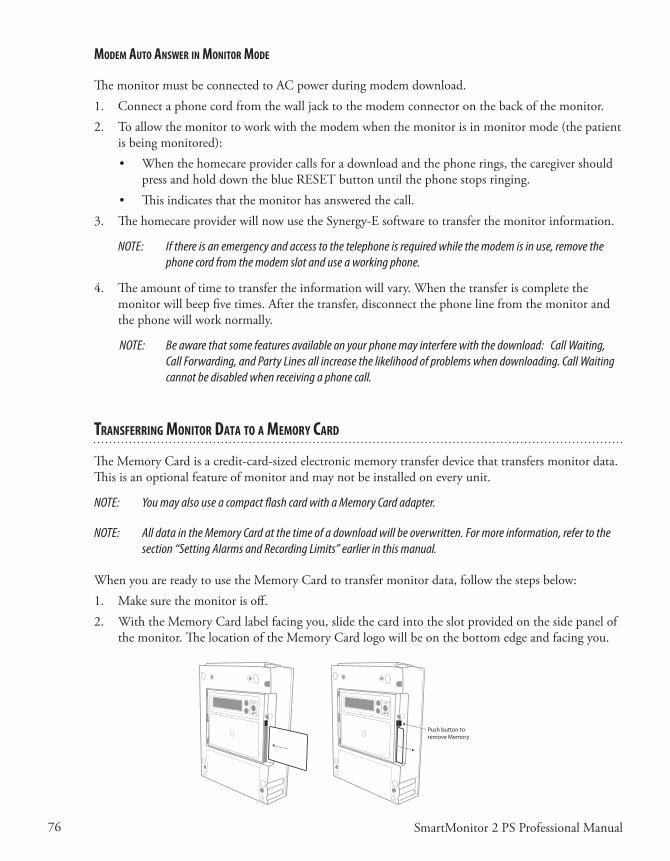
76 SmartMonitor 2 PS Professional Manual
ModeM auTo ansWer In MonITor Mode
ThemonitormustbeconnectedtoACpowerduringmodemdownload.1. Connectaphonecordfromthewalljacktothemodemconnectoronthebackofthemonitor.2. Toallowthemonitortoworkwiththemodemwhenthemonitorisinmonitormode(thepatient
is being monitored):• Whenthehomecareprovidercallsforadownloadandthephonerings,thecaregivershould
pressandholddowntheblueRESETbuttonuntilthephonestopsringing.• Thisindicatesthatthemonitorhasansweredthecall.
3. ThehomecareproviderwillnowusetheSynergy-Esoftwaretotransferthemonitorinformation.
NOTE: If there is an emergency and access to the telephone is required while the modem is in use, remove the phone cord from the modem slot and use a working phone.
4. Theamountoftimetotransfertheinformationwillvary.Whenthetransferiscompletethemonitorwillbeepfivetimes.Afterthetransfer,disconnectthephonelinefromthemonitorandthephonewillworknormally.
NOTE: Be aware that some features available on your phone may interfere with the download: Call Waiting, Call Forwarding, and Party Lines all increase the likelihood of problems when downloading. Call Waiting cannot be disabled when receiving a phone call.
TransferrIng MonITor daTa To a MeMory Card
TheMemoryCardisacredit-card-sizedelectronicmemorytransferdevicethattransfersmonitordata.Thisisanoptionalfeatureofmonitorandmaynotbeinstalledoneveryunit.
NOTE: You may also use a compact flash card with a Memory Card adapter.
NOTE: All data in the Memory Card at the time of a download will be overwritten. For more information, refer to the section “Setting Alarms and Recording Limits” earlier in this manual.
WhenyouarereadytousetheMemoryCardtotransfermonitordata,followthestepsbelow:1. Makesurethemonitorisoff.2. WiththeMemoryCardlabelfacingyou,slidethecardintotheslotprovidedonthesidepanelof
themonitor.ThelocationoftheMemoryCardlogowillbeonthebottomedgeandfacingyou.
enterenter
Push button toremove Memory Card
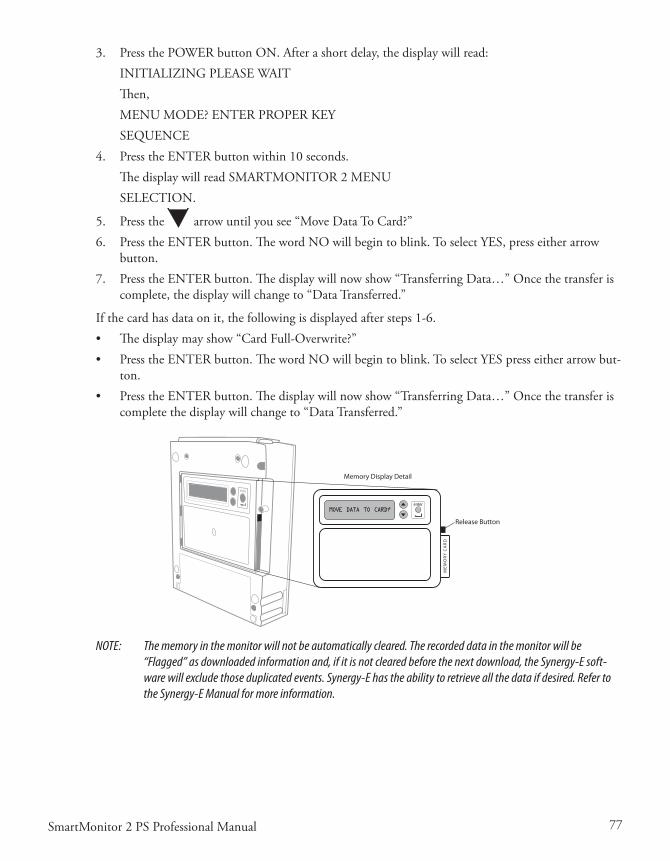
77SmartMonitor 2 PS Professional Manual
3. PressthePOWERbuttonON.Afterashortdelay,thedisplaywillread:INITIALIZINGPLEASEWAITThen,MENUMODE?ENTERPROPERKEYSEQUENCE
4. PresstheENTERbuttonwithin10seconds.ThedisplaywillreadSMARTMONITOR2MENUSELECTION.
5. Pressthe arrowuntilyousee“MoveDataToCard?”6. PresstheENTERbutton.ThewordNOwillbegintoblink.ToselectYES,presseitherarrow
button.7. PresstheENTERbutton.Thedisplaywillnowshow“TransferringData…”Oncethetransferis
complete,thedisplaywillchangeto“DataTransferred.”
Ifthecardhasdataonit,thefollowingisdisplayedaftersteps1-6.• Thedisplaymayshow“CardFull-Overwrite?”• PresstheENTERbutton.ThewordNOwillbegintoblink.ToselectYESpresseitherarrowbut-
ton.• PresstheENTERbutton.Thedisplaywillnowshow“TransferringData…”Oncethetransferis
completethedisplaywillchangeto“DataTransferred.”
Release Button
Memory Display Detail
NOTE: The memory in the monitor will not be automatically cleared. The recorded data in the monitor will be “Flagged” as downloaded information and, if it is not cleared before the next download, the Synergy-E soft-ware will exclude those duplicated events. Synergy-E has the ability to retrieve all the data if desired. Refer to the Synergy-E Manual for more information.

78 SmartMonitor 2 PS Professional Manual
TransferrIng MonITor daTa usIng a CoMpuTer
Datacanbedownloadedfromthemonitorbydirectconnectiontoacomputer.
TheSynergy-Esoftwareisrequiredtodownloadthemonitor.
ThemonitorcanbeplacedinCommunicationModeorMonitoringMode.IfMonitoringModeischosen,allalarmsandrecordparametersarefunctional.
CoMMunICaTIons Mode seTup
The download cable must be connected to the monitor and the computer before turning the monitor on.• ConnectthedownloadcabletotheI/OconnectionsportonthemonitorandtheCOMPorton
thecomputer.• ThemonitorcanbeplacedinCommunicationsMode.• PressandreleasethePOWERbuttontoturnthemonitoron.• PressandholdtheblueRESETbutton.• Waituntilthemonitoralarmsconstantly.• ReleasetheRESETbutton.BrieflypressandreleasetheRESETbuttonagain.Themonitordisplaywillread“MonitorisinCommunicationMode”.• Themonitorbeepsevery10secondswhenitisintheCommunicationsModebutisnotelec-
tronicallyconnectedorlinkedtoanything.Thisisareminderthatthemonitorispoweredonforworkingwiththecomputer,MemoryCard,ormodembutnotformonitoringthepatient.
NOTE: Refer to the Synergy-E software for instruction on Direct Connection Downloading of the monitor.
79SmartMonitor 2 PS Professional Manual
CarIng for The sMarTMonITor 2 psCAUTION: Use the information in this section to keep the monitor functioning well.
CAUTION: Use only Philips Children’s Medical Ventures accessories with the monitor.
CleanIng InsTruCTIons
TurnthemonitorOFF,unplugitfromtheelectricaloutlet,anddisconnectallaccessoriesbeforeyoubegincleaning.
Neverimmersethemonitororanyoftheaccessoriesinwaterorspraycleanerdirectlyonthem.Applywaterorcleanertoasoftclothandgentlywipethecomponentstocleanthem.
MonITor, poWer Cord/baTTery Charger, paTIenT Cables and lead WIres
Useacleanclothandanyofthefollowing:• Unscenteddishwashingdetergent• 3%hydrogenperoxidesolution• 91%Isopropylalcohol• 10%bleachsolution
• GermicidalCloth
eleCTrodes
• Donotattempttocleanthedisposablestyleelectrodes.• Cleanthecarbonelectrodeswithamildsoapandwater.Theymustberinsedwelltoremoveany
tracesofsoapfilm.Soapfilmcanpreventheartandbreathingsignalsfrombeingpickedupclearlybythemonitor.
• Ensurethattheelectrodesarecompletelydrybeforeusing.
sofT CarryIng Case
• Althoughthecarelabelinthecarryingcasesuggestsmachinewashinginwarmwater,theappear-anceofthecarryingcasewillchangenoticeablyafterwashing.
• PhilipsChildren’sMedicalVenturesrecommendsthatyouwipethecasewithadampclothorspongeusingalightdetergent,ifnecessary.Air-dryonly.

80 SmartMonitor 2 PS Professional Manual
InseCT InfesTaTIon deConTaMInaTIon proCedures
1. FumigatingaRoach/Insect-infestedUnit• PlacetheunitinsideaZip-locktypeplasticbag(i.e.,fruit/vegetablebagorlargefreezerbag).• InsertapeststriporRoachMotelinsidethebagwiththeunit.• Sealthebagtightlyandleaveitatroomtemperatureorwarmerforaminimumof30days.
Duringtheincubationperiod,anyinsecteggsinsidetheunitwillhatch.Consequently,theoffspringwillevacuatetheunitandbekilledbythechemicalsfromthepesticide.
• After30days,removetheunitfromthebag.Disposeofthebagandcleantheunitthorough-lyasdirectedbelow.
2. Cleaningtheunit
WARNING: Never clean the monitor while the monitor is in use or the power supply is plugged into an electrical outlet. Never immerse the unit in water. Do not clean the monitor with rubbing alcohol.
• Aftertheaboveprocedureshavebeencompleted,removethebatteryandopentheunitinanESD-protected(grounded,static-free)area.
• Usingde-ionizedcompressedair/gasdustersuitableforuseonelectronics,blowoutalloftheremainsofanyinsectcontamination.
• Closetheunitandre-installthescrewsandbatterypack.• Useacleanclothwithanunscented,alcohol-freedishwashingdetergentor3%Hydrogen
Peroxidesolutiontocleantheoutsideofthemonitor.• Ifnecessary,returntheunittoPhilipsChildren’sMedicalVenturesforrepair.• Unitsunderwarrantywillnotbechargedforlabor/re-certification,butwillbechargedfor
anydamagedorrepairedcomponents.
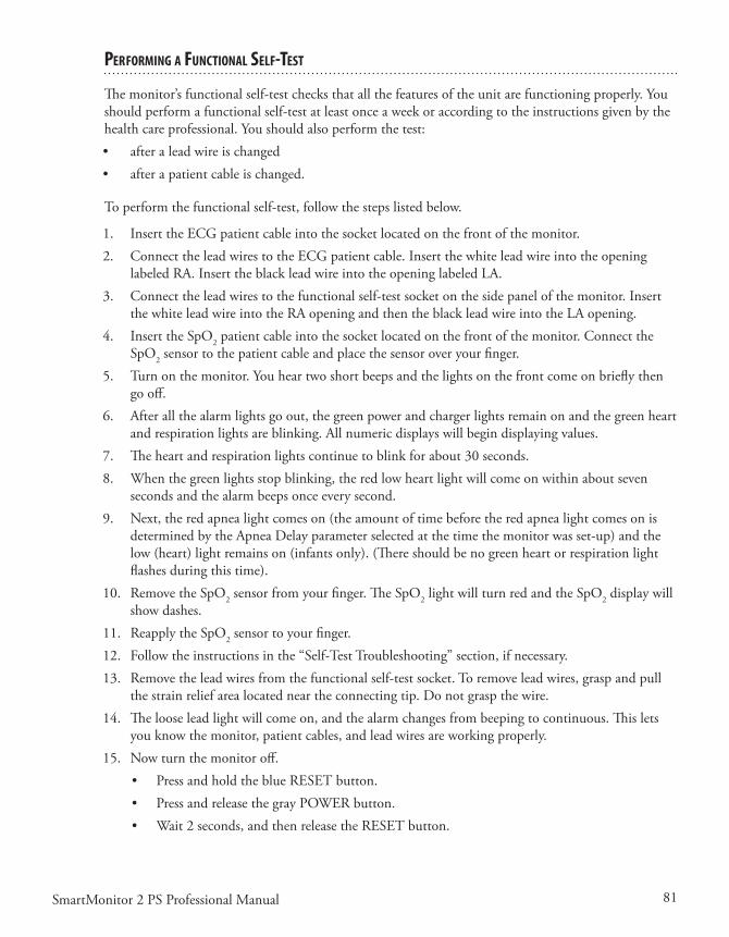
81SmartMonitor 2 PS Professional Manual
perforMIng a funCTIonal self-TesT
Themonitor’sfunctionalself-testchecksthatallthefeaturesoftheunitarefunctioningproperly.Youshould perform a functional self-test at least once a week or according to the instructions given by the healthcareprofessional.Youshouldalsoperformthetest:• afteraleadwireischanged• afterapatientcableischanged.
Toperformthefunctionalself-test,followthestepslistedbelow.
1. InserttheECGpatientcableintothesocketlocatedonthefrontofthemonitor.2. ConnecttheleadwirestotheECGpatientcable.Insertthewhiteleadwireintotheopening
labeledRA.InserttheblackleadwireintotheopeninglabeledLA.3. Connecttheleadwirestothefunctionalself-testsocketonthesidepanelofthemonitor.Insert
thewhiteleadwireintotheRAopeningandthentheblackleadwireintotheLAopening.4. InserttheSpO2patientcableintothesocketlocatedonthefrontofthemonitor.Connectthe
SpO2sensortothepatientcableandplacethesensoroveryourfinger.5. Turnonthemonitor.Youheartwoshortbeepsandthelightsonthefrontcomeonbrieflythen
gooff.6. Afterallthealarmlightsgoout,thegreenpowerandchargerlightsremainonandthegreenheart
andrespirationlightsareblinking.Allnumericdisplayswillbegindisplayingvalues.7. Theheartandrespirationlightscontinuetoblinkforabout30seconds.8. Whenthegreenlightsstopblinking,theredlowheartlightwillcomeonwithinaboutseven
secondsandthealarmbeepsonceeverysecond.9. Next,theredapnealightcomeson(theamountoftimebeforetheredapnealightcomesonis
determinedbytheApneaDelayparameterselectedatthetimethemonitorwasset-up)andthelow(heart)lightremainson(infantsonly).(Thereshouldbenogreenheartorrespirationlightflashesduringthistime).
10. RemovetheSpO2sensorfromyourfinger.TheSpO2 light will turn red and the SpO2 display will showdashes.
11. ReapplytheSpO2sensortoyourfinger.12. Followtheinstructionsinthe“Self-TestTroubleshooting”section,ifnecessary.13. Removetheleadwiresfromthefunctionalself-testsocket.Toremoveleadwires,graspandpull
thestrainreliefarealocatedneartheconnectingtip.Donotgraspthewire.14. Thelooseleadlightwillcomeon,andthealarmchangesfrombeepingtocontinuous.Thislets
youknowthemonitor,patientcables,andleadwiresareworkingproperly.15. Nowturnthemonitoroff.
• PressandholdtheblueRESETbutton.• PressandreleasethegrayPOWERbutton.• Wait2seconds,andthenreleasetheRESETbutton.

82 SmartMonitor 2 PS Professional Manual
self-TesT TroubleshooTIng
Followtheinstructionsgivenbelowifanyoftheconditionsdescribedoccurs.Startthetestoveroncetheproblemhasbeencorrected.
a l a r M C o n d I T I o n s o l u T I o n
Low Battery If the low battery light stays on longer than half a minute, the batteries are completely discharged. • Turn the monitor off using the correct Power Off procedure described in the section
“Turning the Monitor Off – Sibling Alarm” earlier in this manual. • Make sure the power supply is plugged into a live power outlet and is properly con-
nected to the monitor. (See “Charging the Battery” for more information).• Allow the battery to charge approximately 30 minutes. You may then operate the moni-
tor while it is plugged in. Allow the battery to charge for eight hours before using the monitor on battery power.
Memory Full The monitor’s memory has reached the Memory Full parameter. Press the RESET button to silence the alarm. The monitor’s memory needs to be transferred Self-Test may continue.
Loose Lead Indicates loose or bad electrodes, lead wires, and/or patient cable.Check all connections and/or replace lead wires first, then the patient cable(s) if necessary.
WARNING: The monitor’s lights and alarms should respond as described above. If not, contact Philips Children’s Medical Ventures Service before using the unit to monitor a patient.
WARNING: Do not use the monitor if the alarm sounds weak or does not activate twice upon initial startup.

83SmartMonitor 2 PS Professional Manual
TroubleshooTIng
Whenever a technical problem occurs that the caregiver cannot handle, he or she should contact the dealer.Thecaregivershouldnottrytofixthemonitor.
The table below lists some common problems:
p r o b l e M po s s I b l e C a u s e I n s T r u C T I o n s
Monitor will notturn on
The monitor is disconnected from the power cord/battery charger; batteries are discharged.
No Power at outlet.
Defective power cord/battery charger.
Internal part failure.
Plug the power cord/battery charger into the monitor and outlet.
Locate an outlet with power.
Contact Philips Children’s Medical Ventures.
Contact Philips Children’s Medical Ventures.
All lights will flash together and the alarm will beep in unison with the flashing lights. Pressing RESET will not silence alarm.
0001 displayed on bottom LCD display.
1B01 displayed on bottom LCD display.
Internal error condition was detected by the monitor
or
Battery not connected
or
Internal failure with monitor.
Reduce likelihood of electrostatic discharge around the monitor. or Contact Philips Children’s Medical Ventures
If an Error number is displayed on the LCD (the LCD is located on the bottom of the moni-tor), record this information. Contact Philips Children’s Medical Ventures.
If there is an internal software error, a special power off procedure is required.• Press and hold the RESET button. While
still holding down the RESET button, press and hold the POWER button. Hold both buttons down for five seconds
• Release POWER button; continue to hold the RESET button until the monitor turns off.
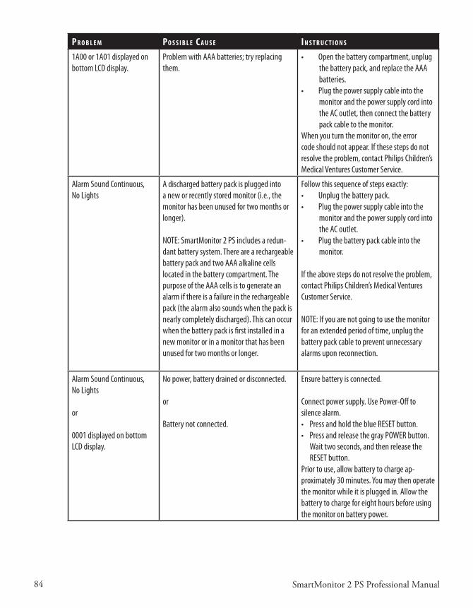
84 SmartMonitor 2 PS Professional Manual
p r o b l e M po s s I b l e C a u s e I n s T r u C T I o n s
1A00 or 1A01 displayed on bottom LCD display.
Problem with AAA batteries; try replacing them.
• Open the battery compartment, unplug the battery pack, and replace the AAA batteries.
• Plug the power supply cable into the monitor and the power supply cord into the AC outlet, then connect the battery pack cable to the monitor.
When you turn the monitor on, the error code should not appear. If these steps do not resolve the problem, contact Philips Children’s Medical Ventures Customer Service.
Alarm Sound Continuous, No Lights
A discharged battery pack is plugged into a new or recently stored monitor (i.e., the monitor has been unused for two months or longer).
NOTE: SmartMonitor 2 PS includes a redun-dant battery system. There are a rechargeable battery pack and two AAA alkaline cells located in the battery compartment. The purpose of the AAA cells is to generate an alarm if there is a failure in the rechargeable pack (the alarm also sounds when the pack is nearly completely discharged). This can occur when the battery pack is first installed in a new monitor or in a monitor that has been unused for two months or longer.
Follow this sequence of steps exactly:• Unplug the battery pack.• Plug the power supply cable into the
monitor and the power supply cord into the AC outlet.
• Plug the battery pack cable into the monitor.
If the above steps do not resolve the problem, contact Philips Children’s Medical Ventures Customer Service.
NOTE: If you are not going to use the monitor for an extended period of time, unplug the battery pack cable to prevent unnecessary alarms upon reconnection.
Alarm Sound Continuous, No Lights
or
0001 displayed on bottom LCD display.
No power, battery drained or disconnected.
or
Battery not connected.
Ensure battery is connected.
Connect power supply. Use Power-Off to silence alarm. • Press and hold the blue RESET button. • Press and release the gray POWER button.
Wait two seconds, and then release the RESET button.
Prior to use, allow battery to charge ap-proximately 30 minutes. You may then operate the monitor while it is plugged in. Allow the battery to charge for eight hours before using the monitor on battery power.
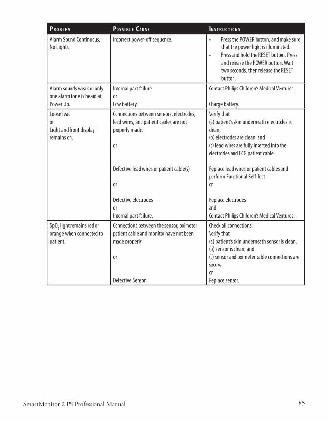
85SmartMonitor 2 PS Professional Manual
p r o b l e M po s s I b l e C a u s e I n s T r u C T I o n s
Alarm Sound Continuous, No Lights
Incorrect power-off sequence. • Press the POWER button, and make sure that the power light is illuminated.
• Press and hold the RESET button. Press and release the POWER button. Wait two seconds, then release the RESET button.
Alarm sounds weak or only one alarm tone is heard at Power Up.
Internal part failureorLow battery.
Contact Philips Children’s Medical Ventures.
Charge battery.
Loose leadorLight and front display remains on.
Connections between sensors, electrodes, lead wires, and patient cables are not properly made.
or
Defective lead wires or patient cable(s)
or
Defective electrodesorInternal part failure.
Verify that (a) patient’s skin underneath electrodes is clean,(b) electrodes are clean, and (c) lead wires are fully inserted into the electrodes and ECG patient cable.
Replace lead wires or patient cables and perform Functional Self-Testor
Replace electrodesandContact Philips Children’s Medical Ventures.
SpO2 light remains red or orange when connected to patient.
Connections between the sensor, oximeter patient cable and monitor have not been made properly
or
Defective Sensor.
Check all connections.Verify that (a) patient’s skin underneath sensor is clean,(b) sensor is clean, and (c) sensor and oximeter cable connections are secureorReplace sensor.
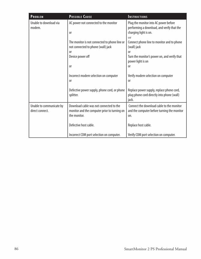
86 SmartMonitor 2 PS Professional Manual
p r o b l e M po s s I b l e C a u s e I n s T r u C T I o n s
Unable to download via modem.
AC power not connected to the monitor
or
The monitor is not connected to phone line or not connected to phone (wall) jackorDevice power off
or
Incorrect modem selection on computer or
Defective power supply, phone cord, or phone splitter.
Plug the monitor into AC power before performing a download, and verify that the charging light is on.orConnect phone line to monitor and to phone (wall) jackorTurn the monitor’s power on, and verify that power light is onor
Verify modem selection on computeror
Replace power supply, replace phone cord, plug phone cord directly into phone (wall) jack.
Unable to communicate by direct connect.
Download cable was not connected to the monitor and the computer prior to turning on the monitor.
Defective host cable.
Incorrect COM port selection on computer.
Connect the download cable to the monitor and the computer before turning the monitor on.
Replace host cable.
Verify COM port selection on computer.

87SmartMonitor 2 PS Professional Manual
SpecificationS
Device Size
Dimensions: 2.25” x 7.25” x 9.0” (5.72 cm x 18.42 cm x 22.86 cm)
Weight: 3.0 lbs. (1.35 kg)
Shipping Weight: 8.5 lbs. (3.9 kg)
electrical ratingS
Power Supply: 100-240 VAC 50/60 Hz 36W
SmartMonitor 2 PS: 12VDC, 3.0 Amps max.
Li Ion Rechargeable Battery Pack: 7.4 VDC, 4.4AH nominal
environmental conDitionS
Operating Temperature: 41º to 104ºF (5ºC to 40ºC)
Operating Humidity: 15% to 95% RH, non-condensing
Storage Temperature: -4º to 140ºF (-20ºC to 60ºC)
Storage Humidity: 15 to 95% RH, non-condensing
Battery Charging Temperature: 50º to 95ºF (10ºC to 35ºC)
StanDarDS compliance
This device is designed to conform to the following standards:
IEC 60601-1 General Requirements for Safety of Medical Electrical Equipment
IEC/EN 60601-1-2:2001 (2nd Edition) Immunity for Medical Electrical Equipment
The SmartMonitor 2 PS system is classified as follows:
Type of protection against electric shock: Class II/Internally Powered
Degree of protection against electric shock: Type BF Applied Part
Degree of protection against ingress of water: IPX1
Mode of operation: Continuous
DiSpoSal
When necessary, dispose of the monitor in accordance with your local regulations. If you are subject to the WEEE/RoHS directives, refer to www.healthcare.philips.com for the passport for recycling this product.
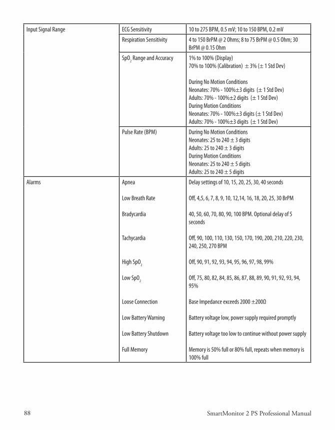
88 SmartMonitor 2 PS Professional Manual
Input Signal Range ECG Sensitivity 10 to 275 BPM, 0.5 mV; 10 to 150 BPM, 0.2 mV
Respiration Sensitivity 4 to 150 BrPM @ 2 Ohms; 8 to 75 BrPM @ 0.5 Ohm; 30 BrPM @ 0.15 Ohm
SpO2 Range and Accuracy 1% to 100% (Display)70% to 100% (Calibration) ± 3% (± 1 Std Dev)
During No Motion Conditions Neonates: 70% - 100%±3 digits (± 1 Std Dev)Adults: 70% - 100%±2 digits (± 1 Std Dev)During Motion Conditions Neonates: 70% - 100%±3 digits (± 1 Std Dev)Adults: 70% - 100%±3 digits (± 1 Std Dev)
Pulse Rate (BPM) During No Motion ConditionsNeonates: 25 to 240 ± 3 digitsAdults: 25 to 240 ± 3 digitsDuring Motion ConditionsNeonates: 25 to 240 ± 5 digitsAdults: 25 to 240 ± 5 digits
Alarms Apnea
Low Breath Rate
Bradycardia
Tachycardia
High SpO2
Low SpO2
Loose Connection
Low Battery Warning
Low Battery Shutdown
Full Memory
Delay settings of 10, 15, 20, 25, 30, 40 seconds
Off, 4,5, 6, 7, 8, 9, 10, 12,14, 16, 18, 20, 25, 30 BrPM
40, 50, 60, 70, 80, 90, 100 BPM. Optional delay of 5 seconds
Off, 90, 100, 110, 130, 150, 170, 190, 200, 210, 220, 230, 240, 250, 270 BPM
Off, 90, 91, 92, 93, 94, 95, 96, 97, 98, 99%
Off, 75, 80, 82, 84, 85, 86, 87, 88, 89, 90, 91, 92, 93, 94, 95%
Base Impedance exceeds 2000 ±200Ω
Battery voltage low, power supply required promptly
Battery voltage too low to continue without power supply
Memory is 50% full or 80% full, repeats when memory is 100% full

89SmartMonitor 2 PS Professional Manual
Memory Capacity Non-Volatile Memory
Logs
Waveform events
4 MB
1000 Patient event listings, 1000 Equipment event listings
500 HR trend and impedance; or 100 ECG QRS, HR trend, and impedance; or 21 hours of continuous HR trend and impedance.
Signal Channels Internal
External Input
QRS, heart rate trend, and impedance (breath rate). Saturation, pulse rate and plethysmograph
Airflow, pH, strain gauge, or other low frequency physi-ological signals, +/- 1.25 V maximum
Event Parameters Internal
Event Duration
Apnea Record (Infants only)
Bradycardia Record
Apnea Record, Apnea Alarm, Low Breath Rate, Bradycardia for Record, Bradycardia Alarm, Tachycardia Alarm, High SpO2 Alarm, Low SpO2 Alarm, Low SpO2 Record
Alarm duration plus current pre- and post-settings totaling 45, 60, 75, 90 seconds
Off or 6 to 40 seconds in two-second intervals
Off or 50 to 100 Beats per Minute in five-BPM intervals

90 SmartMonitor 2 PS Professional Manual
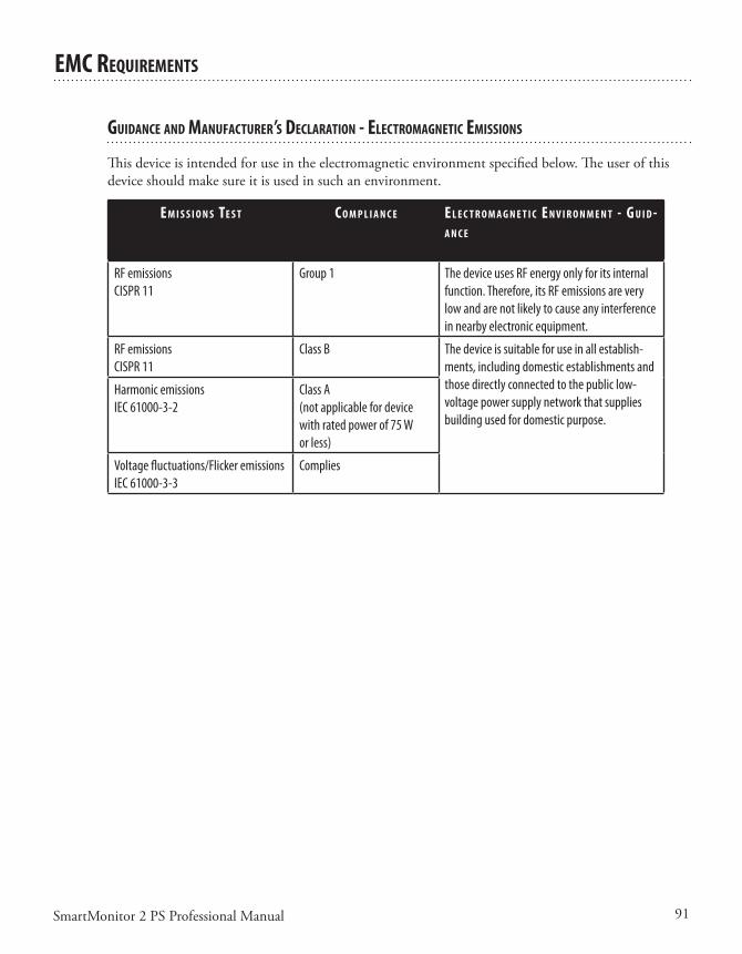
91SmartMonitor 2 PS Professional Manual
eMC requIreMenTs
guIdanCe and ManufaCTurer’s deClaraTIon - eleCTroMagneTIC eMIssIons
Thisdeviceisintendedforuseintheelectromagneticenvironmentspecifiedbelow.Theuserofthisdeviceshouldmakesureitisusedinsuchanenvironment.
e M I s s I o n s Te s T C o M p l I a n C e e l e C T r o M a g n e T I C e n v I r o n M e n T - g u I d -a n C e
RF emissionsCISPR 11
Group 1 The device uses RF energy only for its internal function. Therefore, its RF emissions are very low and are not likely to cause any interference in nearby electronic equipment.
RF emissionsCISPR 11
Class B The device is suitable for use in all establish-ments, including domestic establishments and those directly connected to the public low-voltage power supply network that supplies building used for domestic purpose.
Harmonic emissionsIEC 61000-3-2
Class A(not applicable for device with rated power of 75 W or less)
Voltage fluctuations/Flicker emissionsIEC 61000-3-3
Complies
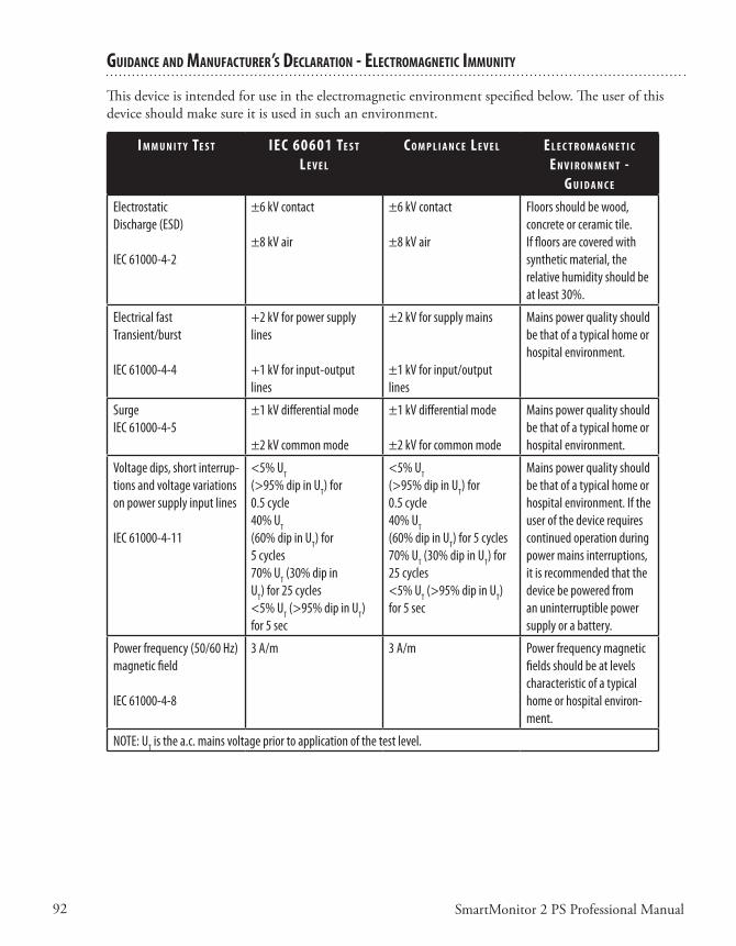
92 SmartMonitor 2 PS Professional Manual
guIdanCe and ManufaCTurer’s deClaraTIon - eleCTroMagneTIC IMMunITy
Thisdeviceisintendedforuseintheelectromagneticenvironmentspecifiedbelow.Theuserofthisdeviceshouldmakesureitisusedinsuchanenvironment.
I M M u n I T y Te s T IeC 60601 Te s T l e v e l
C o M p l I a n C e l e v e l e l e C T r o M a g n e T I C e n v I r o n M e n T -
g u I d a n C e
Electrostatic Discharge (ESD)
IEC 61000-4-2
±6 kV contact
±8 kV air
±6 kV contact
±8 kV air
Floors should be wood, concrete or ceramic tile. If floors are covered with synthetic material, the relative humidity should be at least 30%.
Electrical fast Transient/burst
IEC 61000-4-4
+2 kV for power supply lines
+1 kV for input-output lines
±2 kV for supply mains
±1 kV for input/output lines
Mains power quality should be that of a typical home or hospital environment.
SurgeIEC 61000-4-5
±1 kV differential mode
±2 kV common mode
±1 kV differential mode
±2 kV for common mode
Mains power quality should be that of a typical home or hospital environment.
Voltage dips, short interrup-tions and voltage variations on power supply input lines
IEC 61000-4-11
<5% UT
(>95% dip in UT) for 0.5 cycle 40% UT
(60% dip in UT) for 5 cycles70% UT (30% dip in UT) for 25 cycles <5% UT (>95% dip in UT) for 5 sec
<5% UT
(>95% dip in UT) for 0.5 cycle 40% UT
(60% dip in UT) for 5 cycles70% UT (30% dip in UT) for 25 cycles<5% UT (>95% dip in UT) for 5 sec
Mains power quality should be that of a typical home or hospital environment. If the user of the device requires continued operation during power mains interruptions, it is recommended that the device be powered from an uninterruptible power supply or a battery.
Power frequency (50/60 Hz) magnetic field
IEC 61000-4-8
3 A/m 3 A/m Power frequency magnetic fields should be at levels characteristic of a typical home or hospital environ-ment.
NOTE: UT is the a.c. mains voltage prior to application of the test level.
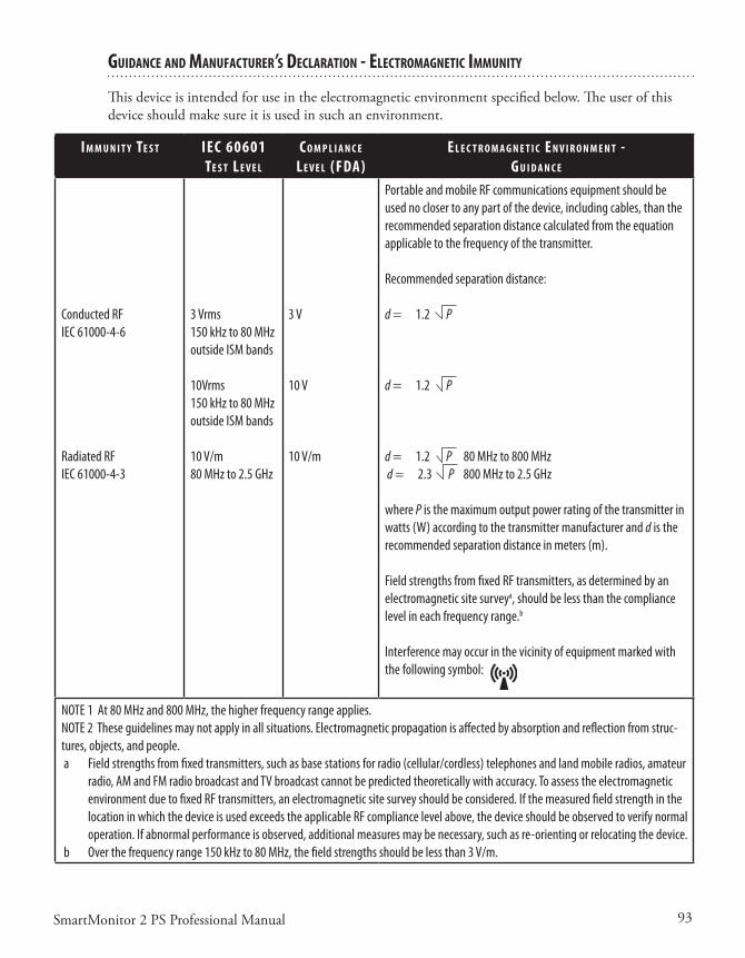
93SmartMonitor 2 PS Professional Manual
guIdanCe and ManufaCTurer’s deClaraTIon - eleCTroMagneTIC IMMunITy
Thisdeviceisintendedforuseintheelectromagneticenvironmentspecifiedbelow.Theuserofthisdeviceshouldmakesureitisusedinsuchanenvironment.
I M M u n I T y Te s T IeC 60601 Te s T l e v e l
C o M p l I a n C e l e v e l (fda)
e l e C T r o M a g n e T I C e n v I r o n M e n T -g u I d a n C e
Conducted RFIEC 61000-4-6
Radiated RFIEC 61000-4-3
3 Vrms150 kHz to 80 MHz outside ISM bands
10Vrms150 kHz to 80 MHz outside ISM bands
10 V/m80 MHz to 2.5 GHz
3 V
10 V
10 V/m
Portable and mobile RF communications equipment should be used no closer to any part of the device, including cables, than the recommended separation distance calculated from the equation applicable to the frequency of the transmitter.
Recommended separation distance:
d = 1.2 P
d = 1.2 P
d = 1.2 P 80 MHz to 800 MHz d = 2.3 P 800 MHz to 2.5 GHz
where P is the maximum output power rating of the transmitter in watts (W) according to the transmitter manufacturer and d is the recommended separation distance in meters (m).
Field strengths from fixed RF transmitters, as determined by an electromagnetic site surveya, should be less than the compliance level in each frequency range.b
Interference may occur in the vicinity of equipment marked with the following symbol:
NOTE 1 At 80 MHz and 800 MHz, the higher frequency range applies.NOTE 2 These guidelines may not apply in all situations. Electromagnetic propagation is affected by absorption and reflection from struc-tures, objects, and people. a Field strengths from fixed transmitters, such as base stations for radio (cellular/cordless) telephones and land mobile radios, amateur
radio, AM and FM radio broadcast and TV broadcast cannot be predicted theoretically with accuracy. To assess the electromagnetic environment due to fixed RF transmitters, an electromagnetic site survey should be considered. If the measured field strength in the location in which the device is used exceeds the applicable RF compliance level above, the device should be observed to verify normal operation. If abnormal performance is observed, additional measures may be necessary, such as re-orienting or relocating the device.
b Over the frequency range 150 kHz to 80 MHz, the field strengths should be less than 3 V/m.
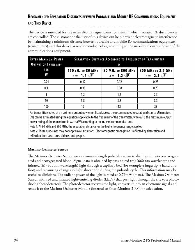
94 SmartMonitor 2 PS Professional Manual
Recommended SepaRation diStanceS between poRtable and mobile RF communicationS equipment and thiS device
The device is intended for use in an electromagnetic environment in which radiated RF disturbances are controlled. The customer or the user of this device can help prevent electromagnetic interference by maintaining a minimum distance between portable and mobile RF communications equipment (transmitters) and this device as recommended below, according to the maximum output power of the communications equipment.
R at e d m a x i m u m p o w e R o u t p u t o F t R a n S m i t -
t e R
w
S e pa R at i o n d i S ta n c e a c c o R d i n g t o F R e q u e n c y o F t R a n S m i t t e R m
150 k h z t o 80 mh z
d = 1.2 p80 mh z t o 800 mh z
d = 1.2 p800 mh z t o 2.5 gh z
d = 2.3 p0.01 0.12 0.12 0.23
0.1 0.38 0.38 0.73
1 1.2 1.2 2.3
10 3.8 3.8 7.3
100 12 12 23
For transmitters rated at a maximum output power not listed above, the recommended separation distance d in meters (m) can be estimated using the equation applicable to the frequency of the transmitter, where P is the maximum output power rating of the transmitter in watts (W) according to the transmitter manufacturer.Note 1: At 80 MHz and 800 MHz, the separation distance for the higher frequency range applies.Note 2: These guidelines may not apply in all situations. Electromagnetic propagation is affected by absorption and reflection from structures, objects, and people.
Masimo Oximeter Sensor
The Masimo Oximeter Sensor uses a two-wavelength pulsatile system to distinguish between oxygen-ated and deoxygenated blood. Signal data is obtained by passing red (rd) (660 nm wavelength) and infrared (ir) (905 nm wavelength) light through a capillary bed (for example a fingertip, a hand or a foot) and measuring changes in light absorption during the pulsatile cycle. This information may be useful to clinicians. The radiant power of the light is rated at 0.79mW (max.). The Masimo Oximeter Sensor with red and infrared light-emitting diodes (LEDs) that pass light through the site to a photo-diode (photodetector). The photodetector receives the light, converts it into an electronic signal and sends it to the Masimo Oximeter Module (internal to SmartMonitor 2 PS) for calculation.

95SmartMonitor 2 PS Professional Manual
glossary
Apnea–Thecessationofbreathing(respirations).
Centralapnea–Norespiratoryeffort.
Obstructiveapnea–Cessationofairflowintooroutofthemouthornosealthougheffortstobreathcontinue.
Bradycardia–Slowingoftheheartratebelowtheagespecifiedrateforfivesecondsorgreater.
CardiopulmonaryResuscitation(CPR)–Aprocedureusedaftercardiacarrestinwhichcardiacmas-sage,mouth-to-mouthresuscitation,anddrugsareusedtorestorebreathing.
Electrode–Aconductorusedtoestablishelectricalcontactbetweenthemonitorandthepatient’sskin.
FunctionalSelf-Test–Auser-performedtesttoverifythemonitor,ECGpatientcable,andleadwiresareworkingproperly.
Heartrate–Thenumberofheartbeatsperminute.
Impedance–Amethodusedbythemonitortodetectrespiration.
LAConnection–TheopeningontheECGpatientcablemarked“LA”istheconnectorfortheblackleadwire.
Modem–Adevicethatallowsthehomecareproviderorhospitaltoworkwithamonitorthroughtelephonelines.
Oximeter–Aphotoelectricdevicethatmeasurestheamountofoxygenandotherfluidsintheblood.
%(Percent)SpO2–Ameasurementofhowmuchoxygeniscontainedinblood.Usuallymeasuredviaafinger,toeorearsensor.NotethattheSpO2measurementindicatesthefunctionalsaturation.
RAConnection–TheopeningontheECGpatientcablemarked“RA”istheconnectorforthewhiteleadwire.
Respiration–Theactofinhalingandexhalingair(breathing).
RLconnection–Useofthethird(green–RL)electrodeandleadwireisnormallynotrequiredbutmayhelpreduceexcessivefalselowheartratealarms.
StrainReliefArea–Locatedattheconnectingtipoftheleadwiresorcables,thisareahasaddedinsulationsurroundingthewirestopreventbreakagewhenhandled.Thisareaistobegraspedwhenremovingleadwires.

96SmartMonitor 2 PS Professional Manual

1SmartMonitor 2 PSL Professional Manual
SmartMonitor 2 PSL

2SmartMonitor 2 PSL Professional Manual

3SmartMonitor 2 PSL Professional Manual
Table of ConTenTs
IntroductIon ....................................................................................................................................7
unpackIng and InspectIon ..............................................................................................7
about thIs Manual .........................................................................................................7
IndIcatIons for use .........................................................................................................7
suMMary of clInIcal perforMance evaluatIon............................................................8
study desIgn ............................................................................................................8
Methods ...................................................................................................................8
WarnIngs and cautIons .............................................................................................................. 13
WarnIngs ....................................................................................................................... 13
cautIons ........................................................................................................................ 15
hoMecare provIder preparatIon for hoMe setup .................................................................... 16
hoW does the sMartMonItor 2 psl Work?............................................................................ 17
syMbols table ........................................................................................................ 18
fcc part 68 telecoM InforMatIon ............................................................................ 19
regIstratIon nuMber and ren ........................................................................... 19
usoc Jack ............................................................................................................ 19
coMplIant accessorIes ......................................................................................... 19
nuMber of rens ................................................................................................... 20
changes In servIce ................................................................................................ 20
probleMs ................................................................................................................ 20
repaIrs .................................................................................................................... 20
party lInes ............................................................................................................ 20
Industry canada requIreMents .................................................................................. 21
Ic abbrevIatIon ..................................................................................................... 21
ren ........................................................................................................................ 21
Industry canada cs-03 notIce ........................................................................ 21
fcc part 15 ........................................................................................................ 22
gettIng to knoW the MonItor .................................................................................................... 23
sMartMonItor 2 psl features .................................................................................. 24
top panel features ............................................................................................... 24
front panel features ........................................................................................... 25
speaker ................................................................................................................... 25
systeM lIghts ........................................................................................................ 26

4 SmartMonitor 2 PSL Professional Manual
sIde panel features .......................................................................................................26
self-test connector .............................................................................................26
MeMory card (optIonal) .....................................................................................27
back panel features......................................................................................................27
nurse call (optIonal) ..........................................................................................27
ModeM (optIonal) ................................................................................................27
I/o connectIons ....................................................................................................28
dc poWer ...............................................................................................................28
stand ..............................................................................................................................28
settIng alarM and recordIng lIMIts...........................................................................................29
Manual setup ................................................................................................................29
the sMartMonItor 2 psl paraMeters .......................................................................................31
systeM setup Menu .......................................................................................................................41
vIeW Menu Mode ...........................................................................................................42
usIng auxIlIary equIpMent ...........................................................................................43
usIng nurse call equIpMent ........................................................................................44
patIent setup .................................................................................................................................45
hospItal Mode ..............................................................................................................................51
respondIng to alarMs ..................................................................................................................53
patIent alarM ................................................................................................................53
testIng the alarM ..........................................................................................................53
If an alarM sounds ......................................................................................................54
respondIng to systeM alarMs ....................................................................................56
reducIng false alarMs .................................................................................................58
MonItorIng ....................................................................................................................................59
turnIng the MonItor on ................................................................................................59
turnIng the MonItor off - sIblIng alarM ..................................................................59
MonItorIng breathIng ..................................................................................................60
respIratIon lIght/dIsplay .....................................................................................60
apnea lIght ............................................................................................................61
MonItorIng heart actIvIty ..........................................................................................62
heart rate lIght/dIsplay ....................................................................................62
hIgh heart rate lIght .........................................................................................62
loW heart rate lIght ...........................................................................................63

5SmartMonitor 2 PSL Professional Manual
portable operatIon of the sMartMonItor 2 psl ....................................................................65
chargIng the MonItor’s battery .................................................................................65
sMartMonItor 2 psl battery pack............................................................................66
battery InstallatIon InstructIons ...............................................................................66
transferrIng sMartMonItor 2 psl InforMatIon ......................................................................69
MeMory ManageMent In the MonItor ........................................................................69
to recover the old data usIng a MeMory card .............................................69
to recover the old data by doWnloadIng usIng synergy-e .........................69
ModeM doWnload ........................................................................................................70
ModeM auto dIal .................................................................................................70
ModeM auto ansWer In coMMunIcatIons Mode ...............................................71
ModeM auto ansWer In MonItor Mode .............................................................72
transferrIng MonItor data to a MeMory card .......................................................72
transferrIng MonItor data usIng a coMputer .........................................................74
coMMunIcatIons Mode setup ...............................................................................74
carIng for the sMartMonItor 2 psl .........................................................................................75
cleanIng InstructIons ...................................................................................................75
electrodes ..............................................................................................................75
soft carryIng case ...............................................................................................75
Insect InfestatIon decontaMInatIon procedures ...............................................76
perforMIng a functIonal self-test .............................................................................76
self-test troubleshootIng ...........................................................................................77
troubleshootIng ............................................................................................................................79
specIfIcatIons .................................................................................................................................83
devIce sIze ..............................................................................................................83
electrIcal ratIngs .................................................................................................83
envIronMental condItIons ...................................................................................83
dIsposal ..................................................................................................................83
eMc requIreMents ........................................................................................................................85
glossary.........................................................................................................................................89

6 SmartMonitor 2 PSL Professional Manual
7SmartMonitor 2 PSL Professional Manual
InTroduCTIon
unpaCkIng and InspeCTIon
When you receive the SmartMonitor 2 PSL, unpack the shipping case and do the following:• Carefullyexaminethecontents.• Savetheshippingcarton.• Makesureyouhaveallthenecessaryitemsandthattheyarenotdamaged.• ReportanythingmissingordamagedtoPhilipsChildren’sMedicalVentures.
abouT ThIs Manual
This manual provides all the information you need to set up and operate the SmartMonitor 2 PSL andexplainshowtouseittomonitorthepatient’svitalfunctions.Carefullyreadandunderstandthismanualbeforeusingthesystem.
IndICaTIons for use
The SmartMonitor 2 PSL is intended for use in the continuous monitoring of respiration and heart ratelevelsofinfant,pediatric,andadultpatients.Itdetectsandalarmsforperiodsofhighorlowheartrateandhighorlowbreathrate.Forinfantsonly,itmonitorsandalarmsforcentralapneas.Whenusedasainfant,pediatricoradultmonitor,itisintendedforuseinahospitalenvironment.
TheSmartMonitor2PSLisnotforuseinthehomeenvironment.
WhaT Is The purpose of The sMarTMonITor 2 psl?SmartMonitor2PSLisanapneamonitordesignedtomonitorandrecordthepatient’sbreathing(res-piration)andheart(cardiac)activity.Themonitoralertsyouifanyoftheseactivitiesexceedthelimitsprescribedbythephysician.
Patient alarm limits are set by the health care professional before the monitor is delivered to the patient.Duringmonitoring,whenthebreathingeffort,andheartactivityarenotwithinthesesetboundaries,anindicatorlightcomesonandanalarmsounds.Thismanualexplainshowtosetupthemonitorhowtomonitorthepatient,andhowtotransferinformation.
OtherdevicesmaybeusedwiththeSmartMonitor2PSL.Refertothesection“UsingAuxiliaryEquipment”formoreinformation.
8 SmartMonitor 2 PSL Professional Manual
suMMary of ClInICal perforManCe evaluaTIon
NOTE: The following study involved the SmartMonitor 2 predicate device and is being used as the basis for perfor-mance evaluation of the SmartMonitor 2 PSL. The study was done with infant patients only.
TheSmartMonitor2wasevaluatedinaclinicalstudyaccordingtothemostrecentFDArecommenda-tions.TheserecommendationsareavailableintheGuidanceforApneaMonitor510(k)submission.
sTudy desIgn
Thiswasamulti-center,prospective,non-randomizedstudycarriedoutatsixclinicalsitesintheUnitedStates.Infantsinnurseriesandothersettingsappropriateforattendedmonitoring,whowereconsidered to be appropriate candidates for cardio-respiratory monitoring, were recruited and enrolled inthestudy.
MeThods
Enrollment was competitive, and each site was instructed to continue patient enrollment until a samplesizeofatleast100qualifiedcentralapneaswasobtained.
InClusIon CrITerIa
Spontaneouslybreathing,newborninfant(lessthanorequalto12monthsofage),eithergenderwithoutregardtoethnicity.
Appropriatecandidateforcardio-respiratorymonitoringincludinganyoneormoreofthefollowing:• diagnosisofcardiac,respiratoryorneurologicaldisease• witnessedorsuspectedepisodesofapneaorperiodicbreathing• gestationalagelessthanorequalto36weeks• historyofsibling(s)experiencingALTE’sorSIDS
• patientsrequiringsupplementaloxygen
exClusIon CrITerIa
Anycandidatewithoneormoreofthefollowingwasexcludedfromenrollment:• presenceofanartificialairway• receivingmechanicalventilation• receivingcontinuouspositiveairwaypressure(CPAP)• presenceofacardiacordiaphragmaticpacemaker
EachpatientwasconnectedtoadataacquisitionsystemthatincludedthePhilipsChildren’sMedicalVenturesSmartMonitorandSmartMonitor2,andtheAlicesystem.Respirationandheartratesignalswererecordedusinginfantelectrocardiogramelectrodes.TheAlicesystemwasusedtogatherphysi-ologicalsignalsandrecordsignalsforairflow,breathingeffort,andmovement.
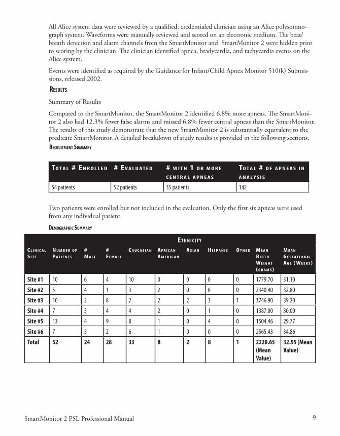
9SmartMonitor 2 PSL Professional Manual
AllAlicesystemdatawerereviewedbyaqualified,credentialedclinicianusinganAlicepolysomno-graphsystem.Waveformsweremanuallyreviewedandscoredonanelectronicmedium.Thebeat/breath detection and alarm channels from the SmartMonitor and SmartMonitor 2 were hidden prior toscoringbytheclinician.Theclinicianidentifiedapnea,bradycardia,andtachycardiaeventsontheAlicesystem.
EventswereidentifiedasrequiredbytheGuidanceforInfant/ChildApneaMonitor510(k)Submis-sions,released2002.
resulTs
SummaryofResults
ComparedtotheSmartMonitor,theSmartMonitor2identified6.8%moreapneas.TheSmartMoni-tor2alsohad12.3%fewerfalsealarmsandmissed6.8%fewercentralapneasthantheSmartMonitor.The results of this study demonstrate that the new SmartMonitor 2 is substantially equivalent to the predicateSmartMonitor.Adetailedbreakdownofstudyresultsisprovidedinthefollowingsections.reCruITMenT suMMary
To T a l # e n r o l l e d # ev a l u a T e d # W I T h 1 o r M o r e C e n T r a l a p n e a s
To T a l # o f a p n e a s I n a n a l y s I s
54 patients 52 patients 35 patients 142
Twopatientswereenrolledbutnotincludedintheevaluation.Onlythefirstsixapneaswereusedfromanyindividualpatient.
deMographIC suMMary
e T h n I C I T y
C l I n I C a l s I T e
n u M b e r o f pa T I e n T s
# M a l e
# fe M a l e
C a u C a s I a n a f r I C a n a M e r I C a n
a s I a n h I s p a n I C o T h e r M e a n b I r T h We I g h T ( g r a M s )
M e a n g e s T a T I o n a l a g e ( We e k s )
Site #1 10 6 4 10 0 0 0 0 1779.70 31.10
Site #2 5 4 1 3 2 0 0 0 2340.40 32.80
Site #3 10 2 8 2 2 2 3 1 3746.90 39.20
Site #4 7 3 4 4 2 0 1 0 1387.00 30.00
Site #5 13 4 9 8 1 0 4 0 1504.46 29.77
Site #6 7 5 2 6 1 0 0 0 2565.43 34.86
Total 52 24 28 33 8 2 8 1 2220.65 (Mean Value)
32.95 (Mean Value)

10 SmartMonitor 2 PSL Professional Manual
dIagnosIs suMMary
d I a g n o s I s s I T e # 1 s I T e #2 s I T e #3 s I T e #4 s I T e #5 s I T e #6 To T a l s b y d I a g n o s I s
Prematurity 10 0 0 7 13 0 30
RDS, Resp. Failure, HMD
3 0 0 3 5 0 11
ALTE, Apnea, AOI, AOP
8 2 8 6 5 4 33
Bronchiolitis, Pneumonia, RSV
0 3 0 1 0 6 10
Gastro-Esopha-geal Reflux
0 0 0 2 1 1 4
Broncho-Pulmo-nary Dysplasia
0 0 0 2 2 0 4
Other 5 2 5 10 10 2 34
Totals by Site 26 7 13 31 36 13 126
resulTs for boTh MonITors by sITe
s T u d y s I T e s M a r T M o n I T o r s M a r T M o n I T o r 2a p n e a W I T h a l a r M
n o a p n e a W I T h a l a r M
a p n e a W I T h o u T a l a r M
a p n e a W I T h a l a r M
n o a p n e a W I T h a l a r M
a p n e a W I T h o u T a l a r M
Site #1 25 21 20 28 21 17
Site #2 2 2 3 2 2 3
Site #3 3 12 6 3 13 6
Site #4 10 21 10 11 11 9
Site #5 21 19 25 18 19 28
Site #6 7 22 10 11 19 6
Totals 68 97 74 73 85 69
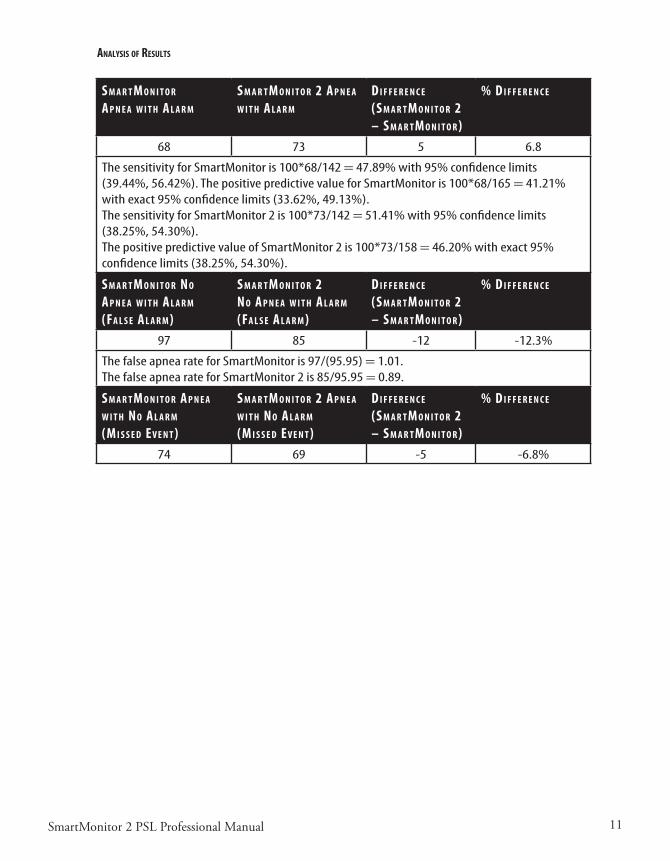
11SmartMonitor 2 PSL Professional Manual
analysIs of resulTs
s M a r T M o n I T o r
a p n e a W I T h a l a r M
s M a r T M o n I T o r 2 a p n e a W I T h a l a r M
d I f f e r e n C e (s M a r T M o n I T o r 2 – s M a r T M o n I T o r )
% d I f f e r e n C e
68 73 5 6.8
The sensitivity for SmartMonitor is 100*68/142 = 47.89% with 95% confidence limits (39.44%, 56.42%). The positive predictive value for SmartMonitor is 100*68/165 = 41.21% with exact 95% confidence limits (33.62%, 49.13%). The sensitivity for SmartMonitor 2 is 100*73/142 = 51.41% with 95% confidence limits (38.25%, 54.30%).The positive predictive value of SmartMonitor 2 is 100*73/158 = 46.20% with exact 95% confidence limits (38.25%, 54.30%).
s M a r T M o n I T o r n o a p n e a W I T h a l a r M
(fa l s e a l a r M )
s M a r T M o n I T o r 2 n o a p n e a W I T h a l a r M
(fa l s e a l a r M )
d I f f e r e n C e (s M a r T M o n I T o r 2 – s M a r T M o n I T o r )
% d I f f e r e n C e
97 85 -12 -12.3%
The false apnea rate for SmartMonitor is 97/(95.95) = 1.01. The false apnea rate for SmartMonitor 2 is 85/95.95 = 0.89.
s M a r T M o n I T o r a p n e a W I T h n o a l a r M
(M I s s e d ev e n T )
s M a r T M o n I T o r 2 a p n e a W I T h n o a l a r M
(M I s s e d ev e n T )
d I f f e r e n C e (s M a r T M o n I T o r 2 – s M a r T M o n I T o r )
% d I f f e r e n C e
74 69 -5 -6.8%

12 SmartMonitor 2 PSL Professional Manual

13SmartMonitor 2 PSL Professional Manual
WarnIngs and CauTIons
CAUTION! U.S. federal law restricts this device to sale by or on the order of a physician.
WarnIngs
A warning indicates the possibility of injury to the user or the operator.
• Beforeusingthemonitor,chargetheinternalbatterypack.Connectthepowersupplytothedevice,andensurethatitispluggedintoafunctionalACwalloutletforaminimumof12hours.
• Themonitorwillnotoperatewithouttheinternalbatterypack.However,theinternalbatterypackensurespropershutdownintheeventofpowerfailuretothedevice.Withouttheinternalbatterypack,lossofdataispossibleintheeventofpowerloss.
• Placethemonitoronasecureandlevelsurfacetopreventthedevicefromfalling.Donotplacethemonitoronthefloororinanylocationwherethedevicecouldbecomeatrippinghazard.Donotplacethemonitorinacrib,sothatthepatientwillnotrollontothedevice’shardsurface.
• Ifanemergencyoccursandaccesstothetelephoneisrequiredwhilethemonitorisconnectedtothe telephone wall jack, unplug the phone cord from the wall jack and connect a working tele-phonetothejack.
• Donotdefibrillateapatientwhoisattachedtothemonitor.• Donotuseskincreams,electrodegels,oilsorlotionsunderthesensors.• Themonitormaynotbeabletodetectallepisodesofinadequatebreathing.Ifapatienthasapnea
duetochoking(obstructiveapnea),themonitorcouldmistakemovementcausedbychokingforbreathing.
• TheSmartMonitor2PSLisamonitoringdeviceonly.Theydonotpreventthelossofbreathingorheartactivity,norwilltheyrestorebreathingorheartactivity.Thesedeviceswillnotpreventdeath.
• AnyoneusingtheSmartMonitor2PSLshouldbetrainedincurrentinfant/adultCardiopulmo-naryResuscitation(CPR),whichisaproperwaytorestorebreathingandheartactivity.
• Themonitorisnotintendedforusewithcardiacordiaphragmaticpacemakerpatients.• Donotallowthepatientcables,leadwires,sensorcablesorpowersupplycabletobecome
tangled,coiled,crossed,orwrappedaroundthepatient’sneck,arms,orlegs.Thiscouldresultinstrangulation.
• Donotblockthespeakerorplaceitemsinfrontofthespeakerlocatedonthefrontoftheunit.Thiscouldpreventthemonitoralarmfrombeingheard.
• Neverusethemonitoronthepatientwhilethepatientisbeingbathed.Thiscouldresultinelec-tricalshockand/ordamagetotheequipment.
• Disconnectthepowersupplyandphonelineduringlightningstormstoreduceriskofelectricalshocktothepatient.
• Ifmonitoringtwoormorepatientsinthesamearea,keepthemonitors,patient,patientcablesandleadwiresatleastthree(3)feetapart.Havingthepatientcablesandleadwiresclosetogethermaycausemissedapneasduetointerference.

14 SmartMonitor 2 PSL Professional Manual
• DonotconnectthepatienttothemonitorifthemonitorisplacedintheCommunicationsMode.Thealarmsdonotworkwhenthemonitorisinthismode.
• Donotusethemonitoratthesametimeasotherimpedancemonitors.Thismaycausemissedapneasduetointerference.
• Donotrockthepatientorsleepinthesamebedwiththepatientwhilemonitoring.Touchingormovingnearthepatient,monitor,orcablescouldcausethemonitortomissapneas.
• Inspectthepowercordsandcablesoftenforanysignsofdamage.Replaceadamagedcordorcableimmediately.
• Donotusenon-safetystyleleadwiresandpatientcableconfigurationswiththismonitor.Theirusemayposeariskofsevereelectricalshockordeath.Refertotheinstructionsinthismanualtoensureproperconnections.UseonlyPhilipsChildren’sMedicalVenturesrecommendedsafetyleadwires,patientcables,electrodesandsensors.
• PinsofconnectorsidentifiedwiththeESDwarningsymbolshouldnotbetouched.Connec-tionsshouldnotbemadetotheseconnectorsunlessESDprecautionaryproceduresareused.Precautionaryproceduresincludemethodstopreventbuild-upofelectrostaticdischarge(e.g.,airconditioning,humidification,conductivefloorcoverings,non-syntheticclothing),dischargingone’sbodytotheframeoftheequipmentorsystemortoearthoralargemetalobject,andbond-ingoneselfbymeansofawriststraptotheequipmentorsystemortoearth.
• Donottouchthedeviceandthepatientsimultaneously.• Theconductivepartsofelectrodesandpatientcablesshouldnotcontactotherconductiveparts,
includingearth.• DonotuseduringHighFrequencysurgicalprocedures.• Explosionhazard.Donotusethemonitorinthepresenceofflammableanestheticsorotherflam-
mablesubstancesincombinationwithair,oxygen-enrichedenvironments,ornitrousoxide.• Ifanalarmconditionoccurswhilethealarmsilenceperiodisactive,theonlyalarmindications
willbevisualdisplaysandsymbolsrelatedtothealarmcondition.• Themonitoristobeoperatedbyqualifiedpersonnelonly.Thismanual,accessorydirectionsfor
use,allprecautionaryinformation,andspecificationsshouldbereadbeforeuse.• Donotusedamagedpatientcables.Donotimmersethepatientcablesinwater,solvents,or
cleaningsolutions.(Thepatientcableconnectorsarenotwaterproof.)Donotsterilizebyirradia-tion,steamorethyleneoxide.Seethecleaninginstructionsinthedirectionsforuseforreusablepatientcables.
• TheNurseCallfeatureofthisdeviceisforconvenienceonlyinamedicallysupervisedenviron-ment.TheaudibleindicationprovidedbytheNurseCallsystemisnottoberelieduponastheprimaryindicationoftheoperatingstateofthedeviceorofpatientevents.
• TheNurseCallfeatureshouldbeconsideredabackuptothemonitordevice’sprimaryalarmsystem.TheoperatorshouldnotrelysolelyontheNurseCallfeature.
15SmartMonitor 2 PSL Professional Manual
CauTIons
A caution indicates the possibility of damage to the device.
• Performthefunctionalself-testifthemonitorhasbeenx-rayedbyanairportsecuritycheck.• Donotsendinformationviamodemduringelectricalstorms.Informationcouldbelost,or
equipmentcouldbedamaged.• Handletheleadwirescarefullytopreventthemfrombreakinginsidetheinsulation.Alwaysgrasp
theleadwireatthestrainreliefareatoremovethemfromtheelectrodesorECGpatientcable.• Anyforeignmatterthatgetsintotheenclosureofthemonitormaycausemalfunction.• UseonlyPhilipsChildren’sMedicalVentures-suppliedsensorsandaccessories.Useofotheracces-
soriescoulddegradesignalquality.• Ifyounoticeanyunexplainedchangesintheperformanceofthisdevice,ifitismakingunusual
or harsh sounds, if the device is dropped or mishandled, if water is spilled into the enclosure, or if theenclosureisbroken,discontinueuseandcontactyourhomecareprovider.
• Ifthepatientisbreathingquietlyandtherespirationlightflashesmoreorfewertimesthanthepatientbreathes,contactPhilipsChildren’sMedicalVenturesforservice.
• Insomelocations,themonitorwillnotworkproperly.Ifthemonitorisaffectedbyexternalinterferenceinthearea,youmaynotbeabletousethemonitor.ContactPhilipsChildren’sMedi-calVenturesforfurtherassistance.Useofathird(RL)electrodeandleadwireisnormallynotrequiredbutmayhelpreduceexcessivefalselowheartratealarms.

16 SmartMonitor 2 PSL Professional Manual

17SmartMonitor 2 PSL Professional Manual
hoW does The sMarTMonITor 2 psl Work?TheSmartMonitor2PSLmonitorsandrecordsapatient’sbreathing(respiration),andheart(cardiac)activity,andalertsthecaregiverifanyoftheseactivitiesexceedsthelimitsprescribedbythephysician.
Thepatientalarmlimitsaresetbeforethemonitorisgiventothepatient.Ifduringmonitoringthepatient’sbreathingeffort,andheartactivityarenotwithinthesesetboundaries,anindicatorlightcomesonandanalarmsounds.
ThismanualexplainshowtosetuptheSmartMonitor2PSL,howtomonitorapatient,howtotrans-fertheinformationtothephysician,andhowtouseotherdeviceswithmonitors.
Breathingismeasuredbyplacingtwoelectrodesonthepatient’schestunderhisorherarms.Asthepatient’schestmovesduringbreathing,theimpedancebetweentheelectrodeschanges.Themonitordetectsthesechangestodeterminethepatient’sbreathingeffort.Ifthemonitordoesnotdetectthesechangesinbreathingeffortforlongerthanthephysician-orderedtime,alightwillcomeonandanalarmwillsound.
The monitor also uses the electrodes on the chest to monitor heart activity by picking up the electrical changesproducedbytheheart.Ifthemonitordetectstheheartrateoutsidetherangeorderedbythephysician,alightwillcomeonandanalarmwillsound.
hoW The alarMs operaTe
Wheneverthepatient’sbreathingeffort,andheartactivityarenotwithinthelimitssetbythephysi-cian,anindicatorlightwillcomeonandanalarmwillsound.Themonitorhastwotypesofalarms:patientandsystem.
PatientAlarms:Anintermittentaudibleandvisualindicatoralertsthepatientduringthefollowingalarm events:• Apnea:Patienthasstoppedbreathingforlongerthanthelimitsetbythephysician.• LowBreathRate:Breathrateislowerthanthelimitsetbythephysician.• LowHeartRate:HeartRateislowerthanthelimitsetbythephysician.• HighHeartRate:HeartRateishigherthanthelimitsetbythephysician.SystemAlarms:Aconstantaudibleandvisualalarmindicatesoneofthefollowingmonitorconditions:• Looselead• LooseProbe• LowBattery• MemoryFull• AccidentalPower-Off• InternalSystemError
Lightsonthemonitorindicatewhichoftheseconditionsexists.Seethesection“Monitoring”formoreinformationonalarms.
Themonitormayalsoalarmifthereisaninternalsystemerror.Ifthemonitoralarmsandthelightsarenotilluminated,orifallofthelightsareblinkingon-and-off,lookattheLCDdisplayonthebottomoftheunit.Ifthereisaninternalerror,acodewillbedisplayedandloggedintothememory.DiscontinueuseofthemonitorandcontactCustomerServiceat1-800-345-6443.

18 SmartMonitor 2 PSL Professional Manual
syMbols Table
s y M b o l d e f I n I T I o n
Attention: Consult accompanying documents
Type BF Applied Part (also shows Patient Cable Connector location)
Reset Button
Power Off/On Button
Apnea Alarm Light (infants only)
Respiration Light
Low Heart Rate Alarm Light
High Heart Rate Alarm Light
Low Battery Light
Memory Full Light
Loose Lead Light
Heart Rate Light
Power Light
Charger Light
Power Cord Connection
Input / Output Connection
Modem Port (Optional)
Nurse Call Connection
SN Serial Number
3 / Three Electrodes Per Package
Four Electrodes Per Package
Beats Per Minute
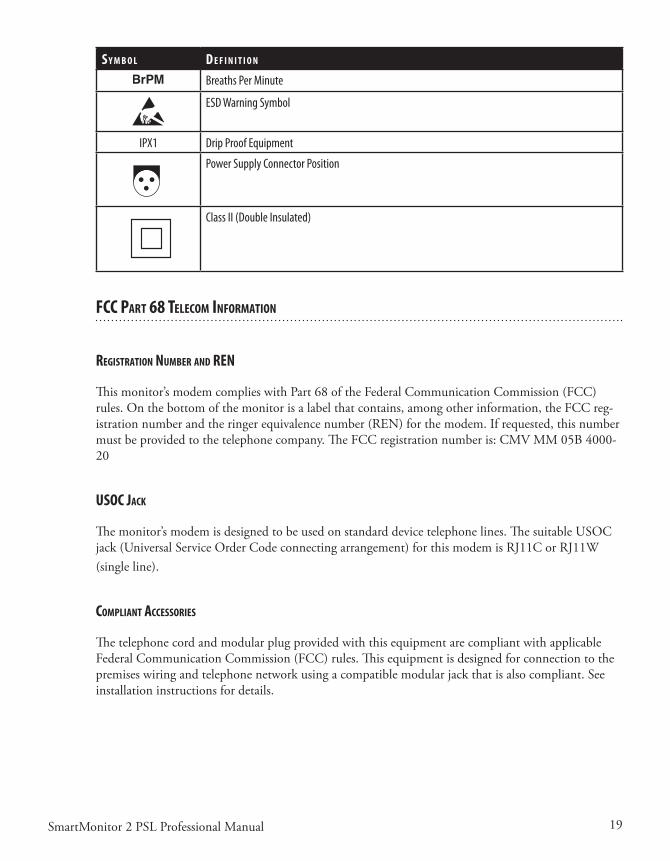
19SmartMonitor 2 PSL Professional Manual
s y M b o l d e f I n I T I o n
Breaths Per Minute
ESD Warning Symbol
IPX1 Drip Proof Equipment
Power Supply Connector Position
Class II (Double Insulated)
fCC parT 68 TeleCoM InforMaTIon
regIsTraTIon nuMber and ren
Thismonitor’smodemcomplieswithPart68oftheFederalCommunicationCommission(FCC)rules.Onthebottomofthemonitorisalabelthatcontains,amongotherinformation,theFCCreg-istrationnumberandtheringerequivalencenumber(REN)forthemodem.Ifrequested,thisnumbermustbeprovidedtothetelephonecompany.TheFCCregistrationnumberis:CMVMM05B4000-20
usoC JaCk
Themonitor’smodemisdesignedtobeusedonstandarddevicetelephonelines.ThesuitableUSOCjack(UniversalServiceOrderCodeconnectingarrangement)forthismodemisRJ11CorRJ11W(singleline).
CoMplIanT aCCessorIes
The telephone cord and modular plug provided with this equipment are compliant with applicable FederalCommunicationCommission(FCC)rules.Thisequipmentisdesignedforconnectiontothepremiseswiringandtelephonenetworkusingacompatiblemodularjackthatisalsocompliant.Seeinstallationinstructionsfordetails.

20 SmartMonitor 2 PSL Professional Manual
nuMber of rens
TheRingerEquivalenceNumber(REN)isusedtodeterminethenumberofdevicesthatmaybecon-nectedtoatelephoneline.ExcessiveRENsonatelephonelinemayresultinthedevicesnotringinginresponsetoanincomingcall.Inmostbutnotallareas,thesumofRENsshouldnotexceedfive(5.0).Tobecertainofthenumberofdevicesthatmaybeconnectedtoaline,asdeterminedbythetotalRENs,contactthelocaltelephonecompany.
CAUTION: If the modem causes harm to the telephone network, the telephone company will notify you in advance that temporary discontinuance of service may be required. But if advance notice is not practical, the telephone company will notify you as soon as possible. Also, you will be advised of your right to file a complaint with the Federal Communications Commission (FCC) if you believe filing a complaint is necessary.
Changes In servICe
The telephone company may make changes in its facilities, equipment, operations, or procedures that couldaffecttheoperationofthisequipment.Ifthishappens,thetelephonecompanywillprovideadvancenoticeinorderforyoutomakenecessarymodificationstomaintainuninterruptedservice.
probleMs
Iftroubleisexperiencedwiththismodem,pleasecontactyourhomecareproviderorPhilipsChildren’sMedicalVenturesat1-800-345-6443forrepairorwarrantyinformation.Iftheequipmentiscausingharm to the telephone network, the telephone company may request that you disconnect the equip-mentuntiltheproblemisresolved.
repaIrs
Norepairsaretobemadebyyou.Wheneveratechnicalproblemoccursthatyoucannothandle,con-tactyourhomecareprovider.Unauthorizedrepairsvoidregistrationandwarranty.
parTy lInes
Connectiontopartylineserviceissubjecttostatetariffs.Contactthestatepublicutilitycommission,publicservicecommissionorcorporationcommissionforinformation.
CAUTION: If your home has specially wired alarm equipment connected to the telephone line, ensure that the installa-tion of the monitor’s modem does not disable your alarm equipment. If you have questions about what will disable alarm equipment, consult your telephone company or a qualified installer.

21SmartMonitor 2 PSL Professional Manual
IndusTry Canada requIreMenTs
IC abbrevIaTIon
ThisequipmentmeetstheapplicableIndustryCanadaTerminalEquipmentTechnicalSpecifications.Thisisconfirmedbytheregistrationnumber.Theabbreviation,IC,beforetheregistrationnumbersig-nifiesthatregistrationwasperformedbasedonaDeclarationofConformityindicatingthatIndustryCanadatechnicalspecificationsweremet.ItdoesnotimplythatIndustryCanadaapprovedtheequip-ment.TheICnumberis:9141A-400020.
ren
TheRingerEquivalenceNumber(REN)forthisterminalequipmentis0.5B.TheRENisanindica-tionofthemaximumnumberofdevicesallowedtobeconnectedtoatelephoneinterface.Thetermi-nation on the interface may consist of any combination of devices subject only to the requirement that thesumoftheRENsofallthedevicesdoesnotexceedfive.
IndusTry Canada Cs-03 noTICe
NOTICE:TheIndustryCanada(IC)labelonthemonitoridentifiescertifiedequipment.Thiscerti-ficationmeansthattheequipmentmeetscertaintelecommunicationsnetworkprotective,operationalandsafetyrequirementsasprescribedintheappropriateTerminalEquipmentTechnicalrequirementsdocument(s).TheDepartmentdoesnotguaranteetheequipmentwilloperatetotheuser’ssatisfaction.
Beforeinstallingthemonitor,usersshouldensurethatitispermissibletobeconnectedtothefacilitiesofthelocaltelecommunicationscompany.Theequipmentmustalsobeinstalledusinganacceptablemethodofconnection.Thecustomershouldbeawarethatcompliancewiththeaboveconditionsmightnotpreventdegradationofserviceinsomesituations.
ThePhilipsChildren’sMedicalVenturesServiceCentershouldcoordinaterepairstocertifiedequip-mentat1-800-345-6443.Anyrepairsoralterationsmadebytheusertothisequipment,orequipmentmalfunctions, may give the telecommunications company cause to request the user to disconnect the equipment.
Usersshouldensure,fortheirownprotection,thattheelectricalgroundconnectionsofthepowerutility,telephonelines,andinternalmetallicwaterpipesystem,ifpresent,areconnectedtogether.Thisprecautionmaybeparticularlyimportantinruralareas.
CAUTION: Users should not attempt to make such connections themselves, but should contact the appropriate electric inspection authority, or electrician, as appropriate.

22 SmartMonitor 2 PSL Professional Manual
fCC parT 15
ThisequipmenthasbeentestedandfoundtocomplywiththelimitsforaClassBdigitaldevice,pur-suanttoPart15oftheFCCrules.Theselimitsaredesignedtoprovidereasonableprotectionagainstharmfulinterferenceinaresidentialinstallation.
Becausethisequipmentgenerates,uses,andcanradiateradiofrequencyenergy,ifitisnotinstalledand used in accordance with the instructions, it may cause harmful interference to radio communica-tions.
However,thereisnoguaranteethatinterferencewillnotoccurinaparticularinstallation.Thiscanbedeterminedbyturningtheequipmentoffandon.Ifthisequipmentdoescauseharmfulinterferencetoradio or television reception, you are encouraged to try to correct the interference by one or more of the following measures:• Reorientorrelocatethereceivingantenna.• Increasetheseparationbetweentheequipmentandreceiver.• Plugtheequipmentintoanoutletonacircuitdifferentfromthattowhichthereceiveriscon-
nected.• Consultthedealeroranexperiencedradio/TVtechnicianforhelp.
ThisdevicecomplieswithPart15oftheFCCrules.Operationofthisdeviceissubjecttothefollow-ing conditions:
(1)Thisdevicemaynotcauseharmfulinterference,and(2)thisdevicemustacceptanyinterferencethatmaycauseundesiredoperation.
CAUTION: Changes or modifications to this unit not expressly approved by the party responsible for compliance could void the user’s authority to operate the equipment.

23SmartMonitor 2 PSL Professional Manual
geTTIng To knoW The MonITor
When you receive the SmartMonitor 2 PSL, make sure that you have all the necessary items and that theyarenotdamaged.ImmediatelyreportanythingmissingordamagedtoPhilipsChildren’sMedicalVentures.
The standard package should include the following:1. SmartMonitor2PSL2. SoftCarryingCase3. PowerSupplyandPowerCord.Yournewmonitorissuppliedwithanexternalpowersupply(P/N
1031372)anda3-wireACinputcord.Ifyoudonothaveagrounded(3-wire)poweroutlet,con-tactPhilipsChildren’sMedicalVenturesCustomerServiceat1-800-345-6443toobtaina2-wirepowersupply(P/N1016966)andACinputcord.The3-wiresupplyandthe2-wiresupplybothprovidethesamelevelofoperatorandpatientsafetyaccordingtoIEC60601-1.However,whenthe monitor is used on a patient who has other medical equipment connected at the same time, the 3-wire power supply may provide greater immunity to electrical noise for the monitor and othermedicalequipment.
NOTE: The appearance of the power supply and cord will vary, depending on country of use. In the illustrations in this guide, the power supply is represented by a standard U.S. domestic 2-wire configuration.
4. ECGPatientCable5. Electrodes6. LeadWires7. Electrodebelt8. Handle/Stand9. BatteryPack10. SymbolReferenceCard(notshownhere)11. PhoneLineSplitter(notshownhere)(optional)12. PhoneLineCord(notshownhere)(optional)

24 SmartMonitor 2 PSL Professional Manual
sMarTMonITor 2 psl feaTures
Thissectiondescribesthephysicalfeaturesofthemonitor.
Top panel feaTures
poWer buTTon
ThegrayPOWERbuttonturnsthemonitoron.Whenyouturnthemonitoron,alllightsandthealarmcomeonbrieflyandthemonitorperformsasystemtest.Afterapause,monitoringwillbegin.
Toturnthemonitoroff,dothefollowing:• PressandholdtheblueRESETbutton.• PressandreleasethegrayPOWERbutton.• Wait2seconds,andthenreleasetheRESETbutton.
NOTE: When the Hospital Mode Control parameter is set to YES, this special key sequence is not required. The alarm set points will also be displayed one at a time during the power up sequence.
When the Hospital Mode Control parameter is set to YES, the Silence Alarm Feature is enabled. This allows the user to silence the audible alarm for 60 seconds when the alarm is being caused by a physiologic event(s). The user can silence the alarm by pressing the RESET button. If the physiologic event(s) is still active after 60 second(s), the alarm will sound again. This feature only affects the audible portion of the alarm. The front panel displays will blink when the silence period is active.
reseT buTTon
TheblueRESETbuttonresetsthealarmlightsonthemonitor.ItalsosilencestheMemoryFull(orMemoryAlmostFull)andLowBatterywarningalarms.Formoreinformation,seethesection“Re-spondingtoAlarms”laterinthismanual.TheRESETbuttonalsoanswersaringingmodemphonecallwheninmonitoringmode.
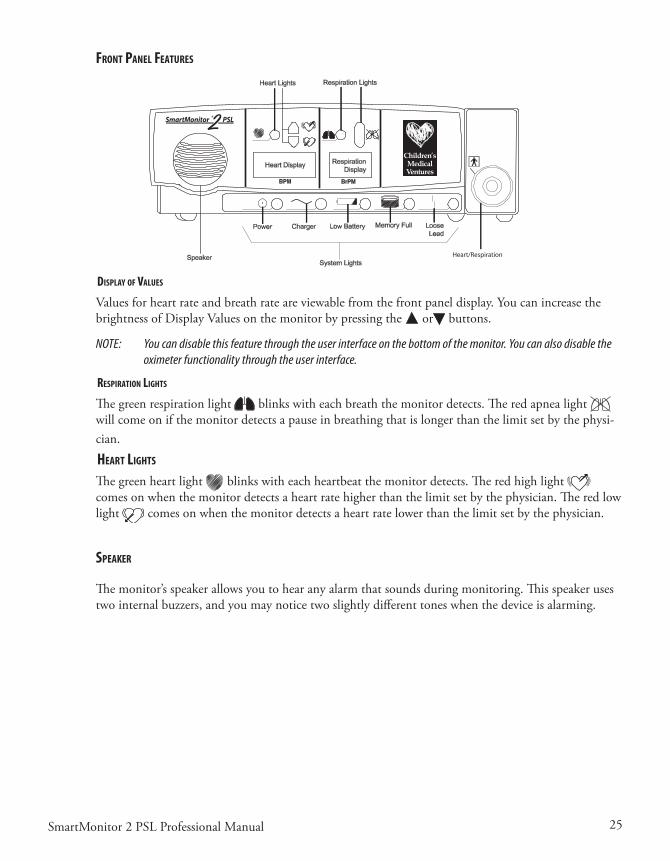
25SmartMonitor 2 PSL Professional Manual
fronT panel feaTures
dIsplay of values
Valuesforheartrateandbreathrateareviewablefromthefrontpaneldisplay.YoucanincreasethebrightnessofDisplayValuesonthemonitorbypressingthe or buttons.
NOTE: You can disable this feature through the user interface on the bottom of the monitor. You can also disable the oximeter functionality through the user interface.
respIraTIon lIghTs
The green respiration light blinkswitheachbreaththemonitordetects.Theredapnealightwill come on if the monitor detects a pause in breathing that is longer than the limit set by the physi-cian.
hearT lIghTs
The green heart light blinkswitheachheartbeatthemonitordetects.Theredhighlight comesonwhenthemonitordetectsaheartratehigherthanthelimitsetbythephysician.Theredlowlight comesonwhenthemonitordetectsaheartratelowerthanthelimitsetbythephysician.
speaker
Themonitor’sspeakerallowsyoutohearanyalarmthatsoundsduringmonitoring.Thisspeakerusestwointernalbuzzers,andyoumaynoticetwoslightlydifferenttoneswhenthedeviceisalarming.

26 SmartMonitor 2 PSL Professional Manual
sysTeM lIghTs
The lights across the bottom of the front panel indicate if the monitor is working properly:
l I g h T I n d I C a T e s
Power The power to the monitor is turned on.
Charger The battery charger is on and plugged into the monitor. (Blinking if charging the battery, solid if battery is fully charged.)
Low battery The battery power is low and needs to be charged.
Memory Full The monitor’s memory is full or almost full.
Loose lead
An electrode, cable, or lead wire connection is loose at one of the plug-in-ports or the electrodes are not making good contact with the patient’s skin.
sIde panel feaTures
Therightsidepanelfeaturesthetwoconnectionsshownbelow.
self-TesT ConneCTor
Youusetheself-testconnectorwhenperformingaFunctionalSelf-Testtomakesuretheleadwires,patientcables,andmonitorareworkingproperly.Seethesection“PerformingaFunctionalSelf-Test”formoreinformation.
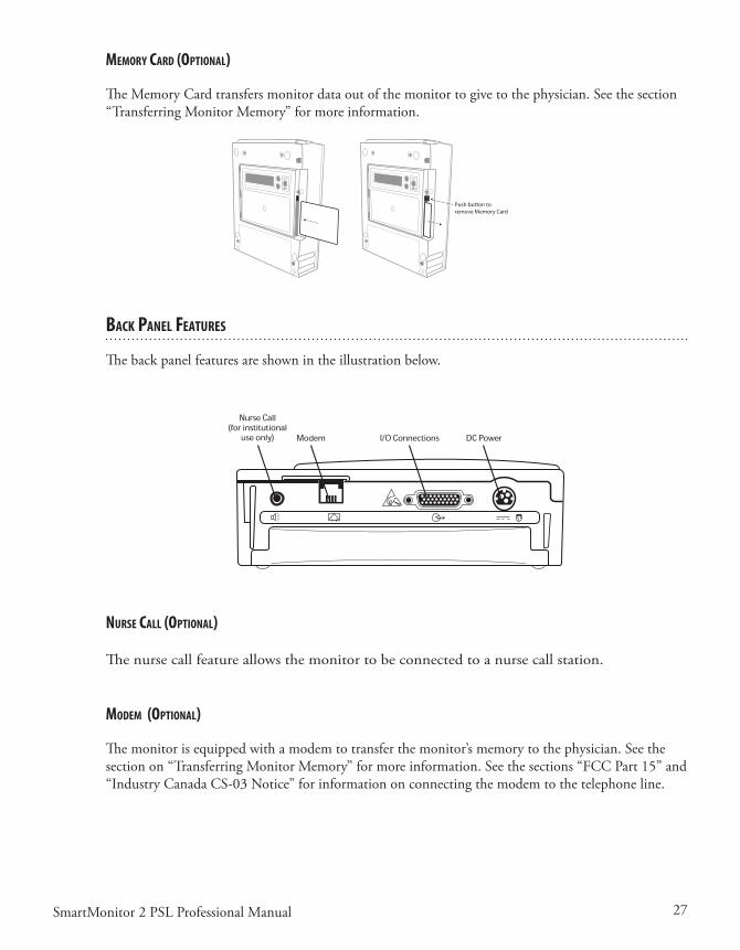
27SmartMonitor 2 PSL Professional Manual
MeMory Card (opTIonal)
TheMemoryCardtransfersmonitordataoutofthemonitortogivetothephysician.Seethesection“TransferringMonitorMemory”formoreinformation.
enterenter
Push button toremove Memory Card
baCk panel feaTures
Thebackpanelfeaturesareshownintheillustrationbelow.
nurse Call (opTIonal)
Thenursecallfeatureallowsthemonitortobeconnectedtoanursecallstation.
ModeM (opTIonal)
Themonitorisequippedwithamodemtotransferthemonitor’smemorytothephysician.Seethesectionon“TransferringMonitorMemory”formoreinformation.Seethesections“FCCPart15”and“IndustryCanadaCS-03Notice”forinformationonconnectingthemodemtothetelephoneline.
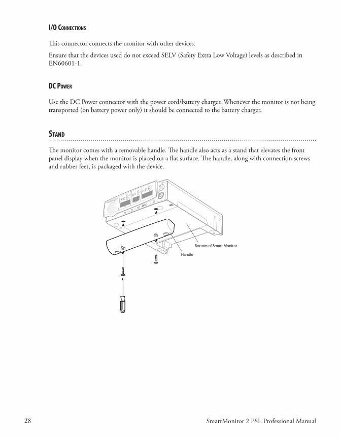
28 SmartMonitor 2 PSL Professional Manual
I/o ConneCTIons
Thisconnectorconnectsthemonitorwithotherdevices.
EnsurethatthedevicesuseddonotexceedSELV(SafetyExtraLowVoltage)levelsasdescribedinEN60601-1.
dC poWer
UsetheDCPowerconnectorwiththepowercord/batterycharger.Wheneverthemonitorisnotbeingtransported(onbatterypoweronly)itshouldbeconnectedtothebatterycharger.
sTand
Themonitorcomeswitharemovablehandle.Thehandlealsoactsasastandthatelevatesthefrontpaneldisplaywhenthemonitorisplacedonaflatsurface.Thehandle,alongwithconnectionscrewsandrubberfeet,ispackagedwiththedevice.
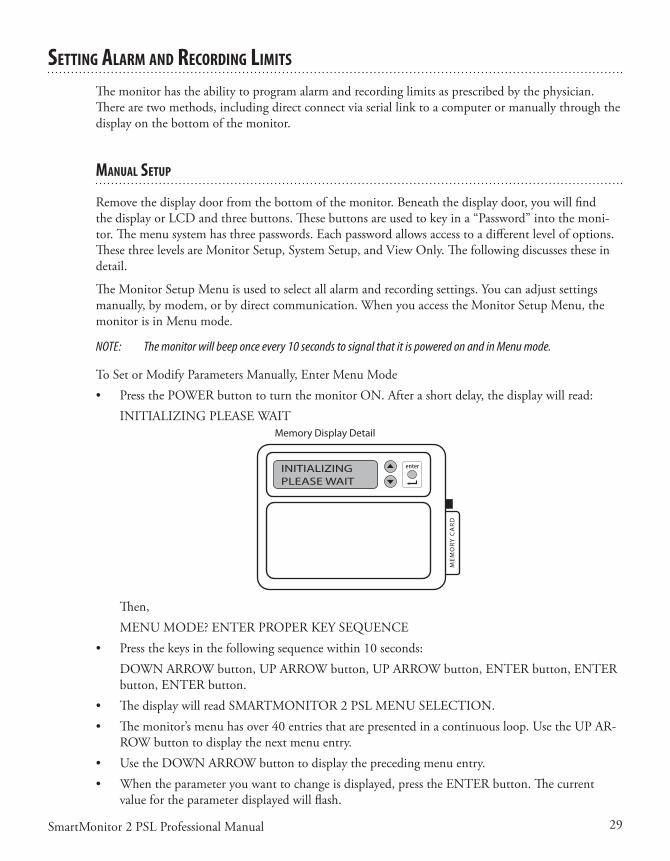
29SmartMonitor 2 PSL Professional Manual
seTTIng alarM and reCordIng lIMITs
Themonitorhastheabilitytoprogramalarmandrecordinglimitsasprescribedbythephysician.There are two methods, including direct connect via serial link to a computer or manually through the displayonthebottomofthemonitor.
Manual seTup
Removethedisplaydoorfromthebottomofthemonitor.Beneaththedisplaydoor,youwillfindthedisplayorLCDandthreebuttons.Thesebuttonsareusedtokeyina“Password”intothemoni-tor.Themenusystemhasthreepasswords.Eachpasswordallowsaccesstoadifferentlevelofoptions.ThesethreelevelsareMonitorSetup,SystemSetup,andViewOnly.Thefollowingdiscussestheseindetail.
TheMonitorSetupMenuisusedtoselectallalarmandrecordingsettings.Youcanadjustsettingsmanually,bymodem,orbydirectcommunication.WhenyouaccesstheMonitorSetupMenu,themonitorisinMenumode.
NOTE: The monitor will beep once every 10 seconds to signal that it is powered on and in Menu mode.
ToSetorModifyParametersManually,EnterMenuMode• PressthePOWERbuttontoturnthemonitorON.Afterashortdelay,thedisplaywillread: INITIALIZINGPLEASEWAIT
Memory Display Detail
INITIALIZINGPLEASE WAIT
Then, MENUMODE?ENTERPROPERKEYSEQUENCE• Pressthekeysinthefollowingsequencewithin10seconds: DOWNARROWbutton,UPARROWbutton,UPARROWbutton,ENTERbutton,ENTER
button,ENTERbutton.• ThedisplaywillreadSMARTMONITOR2PSLMENUSELECTION.• Themonitor’smenuhasover40entriesthatarepresentedinacontinuousloop.UsetheUPAR-
ROWbuttontodisplaythenextmenuentry.• UsetheDOWNARROWbuttontodisplaytheprecedingmenuentry.• Whentheparameteryouwanttochangeisdisplayed,presstheENTERbutton.Thecurrent
valuefortheparameterdisplayedwillflash.
30 SmartMonitor 2 PSL Professional Manual
• Usethe or keytochangetheparametertothedesiredvalue.• Whenthedesiredvalueisdisplayed,presstheENTERbuttontoacceptthevalue.• PresstheUPARROWbuttontochoosethemenupathyouwanttoreview.There are four menu paths to choose from:• AllMenu• AlarmMenu• RecordingMenu• SystemMenu.
Oncethechangesarecompleted,turnthemonitoroffbypressingthefollowingbuttons:• PressandholdtheblueRESETbutton.• PressandreleasethegrayPOWERbutton.• Waittwoseconds,andthenreleasetheRESETbutton.
NOTE: When you power the monitor off and then back on, the new values will be implemented.
When the Hospital Mode Control parameter is set to YES, the special key sequence is not necessary to turn the monitor off.
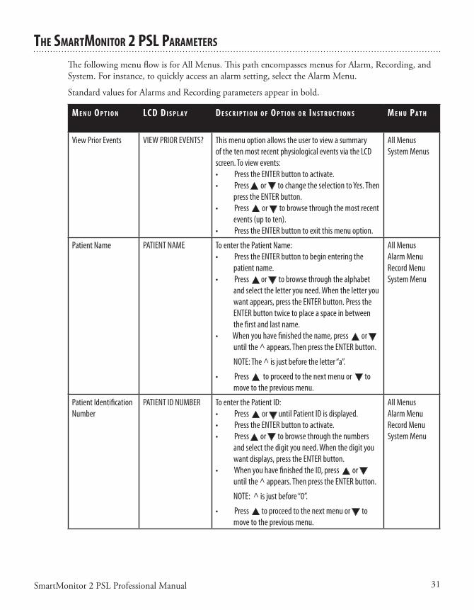
31SmartMonitor 2 PSL Professional Manual
The sMarTMonITor 2 psl paraMeTers
ThefollowingmenuflowisforAllMenus.ThispathencompassesmenusforAlarm,Recording,andSystem.Forinstance,toquicklyaccessanalarmsetting,selecttheAlarmMenu.
StandardvaluesforAlarmsandRecordingparametersappearinbold.
M e n u o p T I o n lCd d I s p l a y d e s C r I p T I o n o f o p T I o n o r I n s T r u C T I o n s M e n u pa T h
View Prior Events VIEW PRIOR EVENTS? This menu option allows the user to view a summary of the ten most recent physiological events via the LCD screen. To view events:• Press the ENTER button to activate.• Press or to change the selection to Yes. Then
press the ENTER button.• Press or to browse through the most recent
events (up to ten).• Press the ENTER button to exit this menu option.
All MenusSystem Menus
Patient Name
PATIENT NAME To enter the Patient Name:• Press the ENTER button to begin entering the
patient name.• Press or to browse through the alphabet
and select the letter you need. When the letter you want appears, press the ENTER button. Press the ENTER button twice to place a space in between the first and last name.
• When you have finished the name, press or until the ^ appears. Then press the ENTER button.
NOTE: The ^ is just before the letter “a”.
• Press to proceed to the next menu or to move to the previous menu.
All MenusAlarm MenuRecord MenuSystem Menu
Patient Identification Number
PATIENT ID NUMBER To enter the Patient ID:• Press or until Patient ID is displayed.• Press the ENTER button to activate.• Press or to browse through the numbers
and select the digit you need. When the digit you want displays, press the ENTER button.
• When you have finished the ID, press or until the ^ appears. Then press the ENTER button.
NOTE: ^ is just before “0”.
• Press to proceed to the next menu or to move to the previous menu.
All MenusAlarm MenuRecord MenuSystem Menu

32 SmartMonitor 2 PSL Professional Manual
M e n u o p T I o n lCd d I s p l a y d e s C r I p T I o n o f o p T I o n o r I n s T r u C T I o n s M e n u pa T h
Standard Alarm Parameters
STD ALARM PARAMETERS
Are SelectedOr
Are Not Selected
• Press the ENTER button to activate.• Press or to change the selection.• When you have your selection displayed, press the
ENTER button.
All MenusAlarm Menu
Standard Record Parameters
STD RECORD PARMS.Are Selected
OrAre Not Selected
• Press the ENTER button to activate.• Press or to change the selection.• When you have your selection displayed, press the
ENTER button.
All MenusRecord Menu
Standard System Parameters
STD SYSTEM PARMS.Are Selected
OrAre Not Selected
• Press the ENTER button to activate.• Press or to change the selection.• When you have your selection displayed, press the
ENTER button.
All MenusSystem Menu
Apnea Alarm Setpoint (Infants only)
APNEA ALARM in seconds
Establishes the amount of time of no respiration detec-tion prior to activation of the apnea alarm.Values:10, 15, 20, 25, 30, 40 secondsStandard value: 20 seconds
All MenusAlarm Menu
Low Breath Rate Alarm Setpoint
LOW BREATH ALARM BrPM
Establishes the alarm set point based on frequency of detected respiratory effort.Values:OFF, 4, 5, 6, 7, 8, 9, 10, 12, 14, 16, 18, 20, 25, 30 breaths per minuteStandard value: OFF
All MenusAlarm Menu
Bradycardia Alarm Setpoint
BRADYCARDIA ALARM BPM
Establishes the LOW heart rate alarm set point based on the average detected ECG signal.Values:40, 50, 60, 70, 80, 90, 100 beats per minuteStandard value: 80 BPM
All MenusAlarm Menu
Bradycardia Alarm Delay
BRADY ALARM DELAY in seconds
Enables a delay to the audible alarmValues:0 or 5 secondsStandard value: 0 seconds
NOTE: If this parameter is set to 5 seconds, the audible alarm will not activate unless the alarm set point is violated for 5 seconds or more.
This is a physician decision and is based on such factors as the known condition of the patient, number of short Bradycardia alarms documented by the monitor, the current Bradycardia alarm set point, and the patient’s average resting heart rate.
All MenusAlarm Menu

33SmartMonitor 2 PSL Professional Manual
M e n u o p T I o n lCd d I s p l a y d e s C r I p T I o n o f o p T I o n o r I n s T r u C T I o n s M e n u pa T h
Tachycardia Alarm Setpoint
TACHYCARDIA ALARM BPM
Establishes the HIGH heart rate alarm set point based on the average ECG signal.Values:OFF, 90, 100, 110, 130, 150, 170, 190, 200, 210, 220, 230, 240, 250, 270 beats per minuteStandard value: 230 BPM
All MenusAlarm Menu
Tachycardia Alarm Delay
TACHY ALARM DELAYIN SECONDS
Enables a delay to the audible alarm.Values:0 and 5 secondsStandard value: 5 seconds
NOTE: If this parameter is set to 5 seconds, the audible alarm will not activate unless the alarm set point is violated for 5 seconds or more.
This is a physician decision and is based on such factors as the known condition of the patient, number of short Tachycardia alarms documented by the monitor, the current Tachycardia alarm set point, and the patient’s average resting heart rate.
All MenusAlarm Menu
Record Mode RECORD MODE Establishes the method that the data is recorded under.Values:EVENT, CONTINUOUS, EVENT LOGStandard value: EVENTEVENT – Active waveforms are recorded each time a patient parameter is violated and an entry is made into the Patient Events Log.EVENT LOG - Patient alarms are acknowledged by an entry in the Patient Events Log but no waveforms are recorded.CONTINUOUS - Active waveforms are recorded continu-ously, regardless of alarm conditions. All equipment-related events are entered in the Equip-ment Events Log.
All MenusRecord Menu
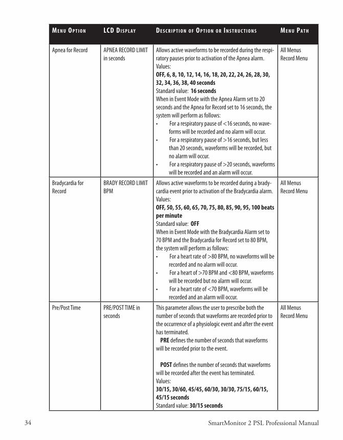
34 SmartMonitor 2 PSL Professional Manual
M e n u o p T I o n lCd d I s p l a y d e s C r I p T I o n o f o p T I o n o r I n s T r u C T I o n s M e n u pa T h
Apnea for Record APNEA RECORD LIMITin seconds
Allows active waveforms to be recorded during the respi-ratory pauses prior to activation of the Apnea alarm.Values:OFF, 6, 8, 10, 12, 14, 16, 18, 20, 22, 24, 26, 28, 30, 32, 34, 36, 38, 40 secondsStandard value: 16 secondsWhen in Event Mode with the Apnea Alarm set to 20 seconds and the Apnea for Record set to 16 seconds, the system will perform as follows:• For a respiratory pause of <16 seconds, no wave-
forms will be recorded and no alarm will occur.• For a respiratory pause of >16 seconds, but less
than 20 seconds, waveforms will be recorded, but no alarm will occur.
• For a respiratory pause of >20 seconds, waveforms will be recorded and an alarm will occur.
All MenusRecord Menu
Bradycardia for Record
BRADY RECORD LIMIT BPM
Allows active waveforms to be recorded during a brady-cardia event prior to activation of the Bradycardia alarm.Values:OFF, 50, 55, 60, 65, 70, 75, 80, 85, 90, 95, 100 beats per minuteStandard value: OFFWhen in Event Mode with the Bradycardia Alarm set to 70 BPM and the Bradycardia for Record set to 80 BPM, the system will perform as follows:• For a heart rate of >80 BPM, no waveforms will be
recorded and no alarm will occur.• For a heart of >70 BPM and <80 BPM, waveforms
will be recorded but no alarm will occur.• For a heart rate of <70 BPM, waveforms will be
recorded and an alarm will occur.
All MenusRecord Menu
Pre/Post Time PRE/POST TIME in seconds
This parameter allows the user to prescribe both the number of seconds that waveforms are recorded prior to the occurrence of a physiologic event and after the event has terminated. PRE defines the number of seconds that waveforms will be recorded prior to the event.
POST defines the number of seconds that waveforms will be recorded after the event has terminated.Values:30/15, 30/60, 45/45, 60/30, 30/30, 75/15, 60/15, 45/15 secondsStandard value: 30/15 seconds
All MenusRecord Menu

35SmartMonitor 2 PSL Professional Manual
M e n u o p T I o n lCd d I s p l a y d e s C r I p T I o n o f o p T I o n o r I n s T r u C T I o n s M e n u pa T h
Impedance Record RECORD IMPEDANCE? This parameter allows the user to select whether or not the respiration waveform will be recorded. Values:YES or NOStandard value: YES
All MenusRecord Menu
Respiration Rate Record
RECORD RESP RATE? This parameter allows the user to select whether or not the Breath-To-Breath and the Average Respiration Rates will be recorded. Values:YES or NOStandard value: YES
All MenusRecord Menu
Heart Rate Record RECORD HEARTRATE? This parameter allows the user to select whether or not the Beat-To-Beat and the Average Heart Rates will be recorded.Values:YES or NOStandard value: YES
All MenusRecord Menu
ECG Record RECORD ECG? This parameter allows the user to select whether or not the ECG waveform will be recorded.Values:YES or NOStandard value: YES
All MenusRecord Menu
Front Panel Control ENABLE PANEL DISPLAY
This parameter allows the user to enable/disable the Front Panel Display. Values:YES and NOStandard value: YES
All MenusSystem Menu
Auxiliary 1 Record RECORD AUXILIARY 1 This parameter allows the user to select whether or not waveforms will be recorded on Auxiliary 1.Standard value: OFFFor additional information, refer to the “Auxiliary Signal Interface” section of this manual.
All MenusRecord Menu
Auxiliary 2 Record RECORD AUXILIARY 2 This parameter allows the user to select whether or not waveforms will be recorded on Auxiliary 2.Standard value: OFFFor additional information, refer to the “Auxiliary Signal Interface” section of this manual.
All MenusRecord Menu
Auxiliary 3 Record RECORD AUXILIARY 3 This parameter allows the user to select whether or not waveforms will be recorded on Auxiliary 3.Standard value: OFFFor additional information, refer to the “Auxiliary Signal Interface” section of this manual.
All MenusRecord Menu

36 SmartMonitor 2 PSL Professional Manual
M e n u o p T I o n lCd d I s p l a y d e s C r I p T I o n o f o p T I o n o r I n s T r u C T I o n s M e n u pa T h
Auxiliary 4 Record RECORD AUXILIARY 4 This parameter allows the user to select whether or not waveforms will be recorded on Auxiliary 4.Standard value: OFFFor additional information, refer to the “Auxiliary Signal Interface” section of this manual.
All MenusRecord Menu
External Physiological Trigger
EXT. PHYSIO TRIGGER Ext. Physio. Trigger allows external equipment to trigger a monitor recording when a physiological parameter is violated in the external auxiliary device. Select from:• OFF• Trigger when high• Trigger when low
See the section “Using Auxiliary Equipment.”
Standard value: OFF
All Menus Record Menu
External Equipment Trigger
EXT. EQUIP. TRIGGER Ext. Equip. Trigger allows external equipment to cause an entry in the monitor’s Equipment Log when an equipment parameter is violated in the external auxiliary device.Select from:• OFF• Trigger when high• Trigger when low
See the section “Using Auxiliary Equipment.”
Standard value: OFF
All MenusRecord Menu
When the auxiliary equipment channels are turned on and the auxiliary equipment is not connected to the monitor, a flat line will be recorded and reported. The auxiliary channels enable you to interface other signals to monitor. Options for each of these channels are best defined with the System Software. External auxiliary devices can be interfaced to provide SpO2, Pulse, EtCO2, pH, or any analog signal in the range of –1.25 to +1.25 volt.The Synergy-E™ software will allow you to customize the channel label, voltage range, and value scale. For instance, an Oxim-eter may have a range of 0-1 volt and a scale of 0-100%. Refer to the Synergy-E Manual for more information.
Date Format Selection DATE FORMAT This parameter allows the user to display the date in either U.S. or international formats
Values:Month/Day/YearDay/Month/YearStandard Value: Month/Day/Year
All MenusSystem Menu
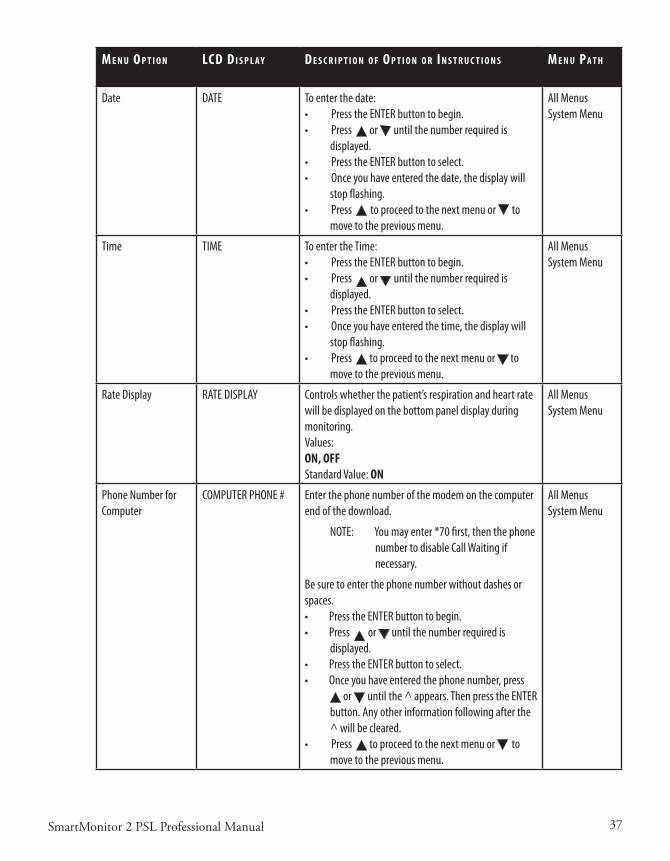
37SmartMonitor 2 PSL Professional Manual
M e n u o p T I o n lCd d I s p l a y d e s C r I p T I o n o f o p T I o n o r I n s T r u C T I o n s M e n u pa T h
Date DATE To enter the date:• Press the ENTER button to begin.• Press or until the number required is
displayed.• Press the ENTER button to select. • Once you have entered the date, the display will
stop flashing. • Press to proceed to the next menu or to
move to the previous menu.
All MenusSystem Menu
Time TIME To enter the Time:• Press the ENTER button to begin.• Press or until the number required is
displayed.• Press the ENTER button to select. • Once you have entered the time, the display will
stop flashing. • Press to proceed to the next menu or to
move to the previous menu.
All MenusSystem Menu
Rate Display RATE DISPLAY Controls whether the patient’s respiration and heart rate will be displayed on the bottom panel display during monitoring.Values:ON, OFFStandard Value: ON
All MenusSystem Menu
Phone Number for Computer
COMPUTER PHONE # Enter the phone number of the modem on the computer end of the download.
NOTE: You may enter *70 first, then the phone number to disable Call Waiting if necessary.
Be sure to enter the phone number without dashes or spaces.• Press the ENTER button to begin.• Press or until the number required is
displayed.• Press the ENTER button to select. • Once you have entered the phone number, press
or until the ^ appears. Then press the ENTER button. Any other information following after the ^ will be cleared.
• Press to proceed to the next menu or to move to the previous menu.
All MenusSystem Menu
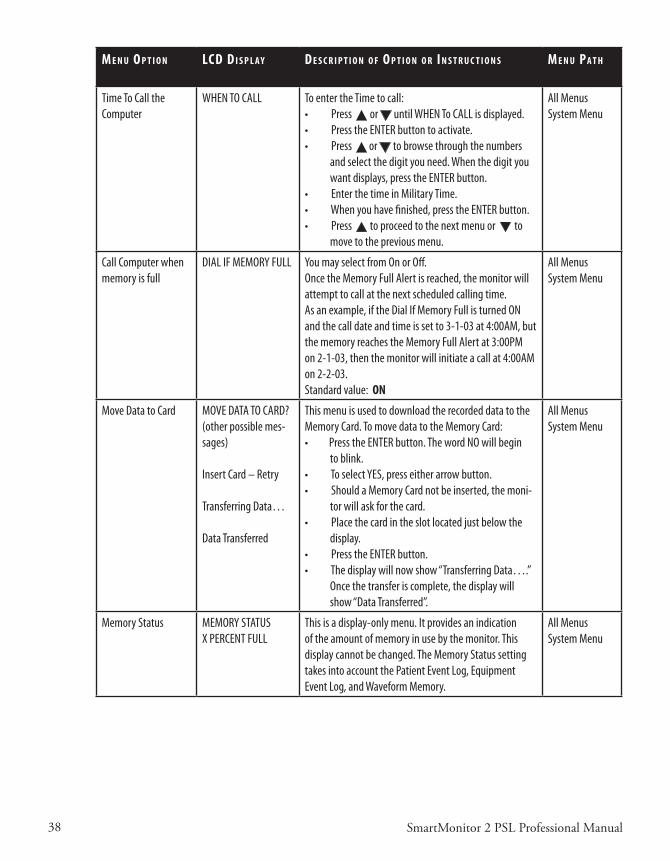
38 SmartMonitor 2 PSL Professional Manual
M e n u o p T I o n lCd d I s p l a y d e s C r I p T I o n o f o p T I o n o r I n s T r u C T I o n s M e n u pa T h
Time To Call the Computer
WHEN TO CALL To enter the Time to call:• Press or until WHEN To CALL is displayed.• Press the ENTER button to activate.• Press or to browse through the numbers
and select the digit you need. When the digit you want displays, press the ENTER button.
• Enter the time in Military Time.• When you have finished, press the ENTER button.• Press to proceed to the next menu or to
move to the previous menu.
All MenusSystem Menu
Call Computer when memory is full
DIAL IF MEMORY FULL You may select from On or Off.Once the Memory Full Alert is reached, the monitor will attempt to call at the next scheduled calling time.As an example, if the Dial If Memory Full is turned ON and the call date and time is set to 3-1-03 at 4:00AM, but the memory reaches the Memory Full Alert at 3:00PM on 2-1-03, then the monitor will initiate a call at 4:00AM on 2-2-03.Standard value: ON
All MenusSystem Menu
Move Data to Card MOVE DATA TO CARD?(other possible mes-sages)
Insert Card – Retry
Transferring Data…
Data Transferred
This menu is used to download the recorded data to the Memory Card. To move data to the Memory Card:• Press the ENTER button. The word NO will begin
to blink.• To select YES, press either arrow button.• Should a Memory Card not be inserted, the moni-
tor will ask for the card.• Place the card in the slot located just below the
display.• Press the ENTER button. • The display will now show “Transferring Data….”
Once the transfer is complete, the display will show “Data Transferred”.
All MenusSystem Menu
Memory Status MEMORY STATUS X PERCENT FULL
This is a display-only menu. It provides an indication of the amount of memory in use by the monitor. This display cannot be changed. The Memory Status setting takes into account the Patient Event Log, Equipment Event Log, and Waveform Memory.
All MenusSystem Menu
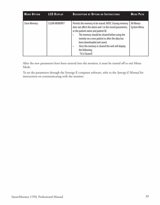
39SmartMonitor 2 PSL Professional Manual
M e n u o p T I o n lCd d I s p l a y d e s C r I p T I o n o f o p T I o n o r I n s T r u C T I o n s M e n u pa T h
Clear Memory CLEAR MEMORY? Permits the memory to be erased. NOTE: Erasing memory does not affect the alarm and / or the record parameters, or the patient name and patient ID. • The memory should be cleared before using the
monitor on a new patient or after the data has been downloaded and saved.
• Once the memory is cleared the unit will display the following:
“It Is Cleared”.
All MenusSystem Menu
Afterthenewparametershavebeenenteredintothemonitor,itmustbeturnedofftoexitMenuMode.
TosettheparametersthroughtheSynergy-Ecomputersoftware,refertotheSynergy-E Manual for instructionsoncommunicatingwiththemonitor.

40 SmartMonitor 2 PSL Professional Manual
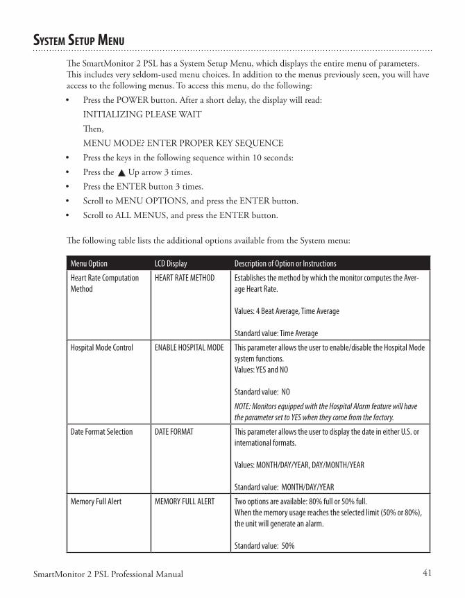
41SmartMonitor 2 PSL Professional Manual
sysTeM seTup Menu
TheSmartMonitor2PSLhasaSystemSetupMenu,whichdisplaystheentiremenuofparameters.Thisincludesveryseldom-usedmenuchoices.Inadditiontothemenuspreviouslyseen,youwillhaveaccesstothefollowingmenus.Toaccessthismenu,dothefollowing:• PressthePOWERbutton.Afterashortdelay,thedisplaywillread: INITIALIZINGPLEASEWAIT Then, MENUMODE?ENTERPROPERKEYSEQUENCE• Pressthekeysinthefollowingsequencewithin10seconds:• Pressthe Uparrow3times.• PresstheENTERbutton3times.• ScrolltoMENUOPTIONS,andpresstheENTERbutton.• ScrolltoALLMENUS,andpresstheENTERbutton.
The following table lists the additional options available from the System menu:
Menu Option LCD Display Description of Option or Instructions
Heart Rate Computation Method
HEART RATE METHOD Establishes the method by which the monitor computes the Aver-age Heart Rate.
Values: 4 Beat Average, Time Average
Standard value: Time Average
Hospital Mode Control ENABLE HOSPITAL MODE This parameter allows the user to enable/disable the Hospital Mode system functions. Values: YES and NO
Standard value: NO
NOTE: Monitors equipped with the Hospital Alarm feature will have the parameter set to YES when they come from the factory.
Date Format Selection DATE FORMAT This parameter allows the user to display the date in either U.S. or international formats.
Values: MONTH/DAY/YEAR, DAY/MONTH/YEAR
Standard value: MONTH/DAY/YEAR
Memory Full Alert MEMORY FULL ALERT Two options are available: 80% full or 50% full. When the memory usage reaches the selected limit (50% or 80%), the unit will generate an alarm.
Standard value: 50%
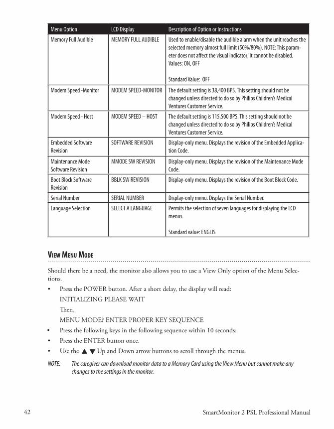
42 SmartMonitor 2 PSL Professional Manual
Menu Option LCD Display Description of Option or Instructions
Memory Full Audible MEMORY FULL AUDIBLE Used to enable/disable the audible alarm when the unit reaches the selected memory almost full limit (50%/80%). NOTE: This param-eter does not affect the visual indicator; it cannot be disabled.Values: ON, OFF
Standard Value: OFF
Modem Speed -Monitor MODEM SPEED-MONITOR The default setting is 38,400 BPS. This setting should not be changed unless directed to do so by Philips Children’s Medical Ventures Customer Service.
Modem Speed - Host MODEM SPEED – HOST The default setting is 115,500 BPS. This setting should not be changed unless directed to do so by Philips Children’s Medical Ventures Customer Service.
Embedded Software Revision
SOFTWARE REVISION Display-only menu. Displays the revision of the Embedded Applica-tion Code.
Maintenance Mode Software Revision
MMODE SW REVISION Display-only menu. Displays the revision of the Maintenance Mode Code.
Boot Block Software Revision
BBLK SW REVISION Display-only menu. Displays the revision of the Boot Block Code.
Serial Number SERIAL NUMBER Display-only menu. Displays the Serial Number.
Language Selection SELECT A LANGUAGE Permits the selection of seven languages for displaying the LCD menus.
Standard value: ENGLIS
vIeW Menu Mode
Shouldtherebeaneed,themonitoralsoallowsyoutouseaViewOnlyoptionoftheMenuSelec-tions.• PressthePOWERbutton.Afterashortdelay,thedisplaywillread: INITIALIZINGPLEASEWAIT Then, MENUMODE?ENTERPROPERKEYSEQUENCE• Pressthefollowingkeysinthefollowingsequencewithin10seconds:• PresstheENTERbuttononce.• Usethe UpandDownarrowbuttonstoscrollthroughthemenus.
NOTE: The caregiver can download monitor data to a Memory Card using the View Menu but cannot make any changes to the settings in the monitor.
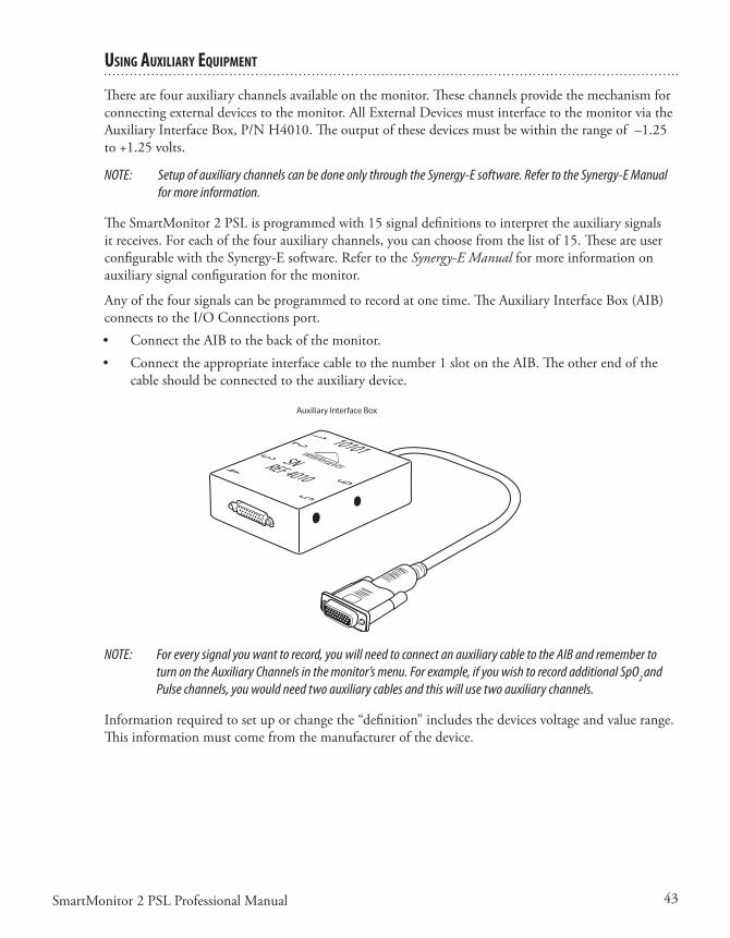
43SmartMonitor 2 PSL Professional Manual
usIng auxIlIary equIpMenT
Therearefourauxiliarychannelsavailableonthemonitor.Thesechannelsprovidethemechanismforconnectingexternaldevicestothemonitor.AllExternalDevicesmustinterfacetothemonitorviatheAuxiliaryInterfaceBox,P/NH4010.Theoutputofthesedevicesmustbewithintherangeof–1.25to+1.25volts.
NOTE: Setup of auxiliary channels can be done only through the Synergy-E software. Refer to the Synergy-E Manual for more information.
TheSmartMonitor2PSLisprogrammedwith15signaldefinitionstointerprettheauxiliarysignalsitreceives.Foreachofthefourauxiliarychannels,youcanchoosefromthelistof15.TheseareuserconfigurablewiththeSynergy-Esoftware.RefertotheSynergy-E Manual for more information on auxiliarysignalconfigurationforthemonitor.
Anyofthefoursignalscanbeprogrammedtorecordatonetime.TheAuxiliaryInterfaceBox(AIB)connectstotheI/OConnectionsport.• ConnecttheAIBtothebackofthemonitor.• Connecttheappropriateinterfacecabletothenumber1slotontheAIB.Theotherendofthe
cableshouldbeconnectedtotheauxiliarydevice.
NOTE: For every signal you want to record, you will need to connect an auxiliary cable to the AIB and remember to turn on the Auxiliary Channels in the monitor’s menu. For example, if you wish to record additional SpO2 and Pulse channels, you would need two auxiliary cables and this will use two auxiliary channels.
Informationrequiredtosetuporchangethe“definition”includesthedevicesvoltageandvaluerange.Thisinformationmustcomefromthemanufacturerofthedevice.
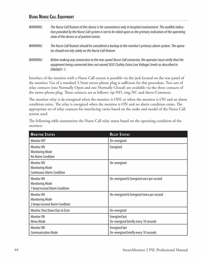
44 SmartMonitor 2 PSL Professional Manual
usIng nurse Call equIpMenT
WARNING: The Nurse Call feature of this device is for convenience only in hospital environment. The audible indica-tion provided by the Nurse Call system is not to be relied upon as the primary indication of the operating state of the device or of patient events.
WARNING: The Nurse Call feature should be considered a backup to the monitor’s primary alarm system. The opera-tor should not rely solely on the Nurse Call feature.
WARNING: Before making any connection to the rear-panel Nurse Call connector, the operator must verify that the equipment being connected does not exceed SELV (Safety Extra Low Voltage) levels as described in EN60601-1.
InterfaceofthemonitorwithaNurseCallsystemispossibleviathejacklocatedontherearpanelofthemonitor.Useofastandard3.5mmstereophoneplugissufficientforthisprocedure.Twosetsofrelaycontacts(oneNormallyOpenandoneNormallyClosed)areavailableviathethreecontactsofthestereophoneplug.Thesecontactsareasfollows:tip-NO,ring-NCandsleeve-Common.
Themonitorrelayisde-energizedwhenthemonitorisOFF,orwhenthemonitorisONandanalarmconditionexists.TherelayisenergizedwhenthemonitorisONandnoalarmconditionexists.TheappropriatesetofrelaycontactsforinterfacingvariesbasedonthemakeandmodeloftheNurseCallsystemused.
ThefollowingtablesummarizestheNurseCallrelaystatusbasedontheoperatingconditionofthemonitor:
M o n I T o r s T a T u s r e l a y s T a T u s
Monitor OFF De-energized
Monitor ONMonitoring ModeNo Alarm Condition
Energized
Monitor ONMonitoring ModeContinuous Alarm Condition
De-energized
Monitor ONMonitoring Mode1 beep/second Alarm Condition
De-energized & Energized once per second
Monitor ONMonitoring Mode2 beeps/second Alarm Condition
De-energized & Energized twice per second
Monitor Shut Down Due to Error De-energized
Monitor ONMenu Mode
Energized butDe-energized briefly every 10 seconds
Monitor ONCommunication Mode
Energized butDe-energized briefly every 10 seconds

45SmartMonitor 2 PSL Professional Manual
paTIenT seTup
Thissectionisanoverviewofthestepsyoushouldfollowtosetupthemonitorinthepatient’shome.Readtheentiremanualpriortorelyinguponthissection(alone)tosetupaSmartMonitor2PSL.• EnsureMemoryhasbeenclearedpriortodeliverytonewpatient.• Reviewuseofthemonitoranditsaccessorieswiththecaregiver(s).BesuretoperformtheFunc-
tionalSelf-Test.Aself-testshouldbeperformedweeklyorwheneverleadwiresorECGpatientcablesarechanged.
• Stresstheimportanceofelectrodepositioning,beltsnugness,cleanelectrodes,andcleanskin.• Leaveyouremergencyphonenumber(s)andprocedureswiththecaregiver(s).
Step 1: Set the monitor on a Clean, Flat Surface.
• Besurethespeakerisnotblocked.• Toavoidinterference,besurethatnootherelectricalappliancesarewithinthreefeetofthemoni-
tor,patient,andpatientleads.• Makesurethemonitoriscloseenoughtoconnecttothepatientcomfortably.
WARNING: The monitor should not be placed in bed with the patient.
Step 2: Connect the ECG Patient Cable to the monitor.
• InserttheroundendoftheECGpatientcableintothebottomroundconnectorfoundonthefrontofthemonitor.
• Lineupthenotchontheconnectorandpushuntilyoufeeltheconnectorsnapintoplace.• ToremovetheECGpatientcable,graspitatthebaseofthepatientinputconnectorandgently
pullstraightback.Youshouldfeeltheoutersleeveslidebackandunlocktheconnectorasyoupull.
CAUTION: Do not twist or turn the ECG patient cable to remove from the monitor as this may cause damage to the ECG patient cable and/or monitor.
WARNING: The ECG patient cable should not be placed over the top of the crib rail. The cable should be placed between the vertical bars.

46 SmartMonitor 2 PSL Professional Manual
Step 3: Connect the Lead Wires to the ECG Patient Cable.
ThelargerendoftheECGpatientcablehasthreeopenings,markedLA(black),RL(green),andRA(white).• TakethewhiteleadwireandinsertitintotheopeningmarkedRA.• TaketheblackleadwireandinsertitintotheopeningmarkedLA.• Firmlypusheachleadwireinuntilthesocketsnapsintoplace.
WARNING: When you need to remove a lead wire, grasp and pull at the strain relief area located near the connecting tip. Do not grasp the wire.
NOTE: Use of the third (green - RL) electrode and lead wire is normally not required but may help reduce excessive false low heart rate alarms.
Step 4: Connect the Lead Wires to the Electrodes.
• InserttheblackLAleadwireintooneelectrode.• InsertthewhiteRAleadwireintotheotherelectrode.• Makesurethemetaltipsoftheleadwiresarefullyinsertedintotheelectrodes.
NOTE: Refer to the section “Disposable Self-Adhesive Electrodes” if applicable.
NOTE: The 3M Red Dot ECG Electrode is compatible for use with the SmartMonitor 2 PSL.
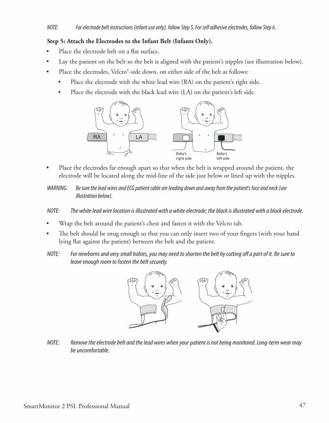
47SmartMonitor 2 PSL Professional Manual
NOTE: For electrode belt instructions (infant use only), follow Step 5. For self adhesive electrodes, follow Step 6.
Step 5: Attach the Electrodes to the Infant Belt (Infants Only).
• Placetheelectrodebeltonaflatsurface.• Laythepatientonthebeltsothebeltisalignedwiththepatient’snipples(seeillustrationbelow).• Placetheelectrodes,Velcro®-sidedown,oneithersideofthebeltasfollows:
• Placetheelectrodewiththewhiteleadwire(RA)onthepatient’srightside.• Placetheelectrodewiththeblackleadwire(LA)onthepatient’sleftside.
Baby’sleft side
Baby’sright side
• Placetheelectrodesfarenoughapartsothatwhenthebeltiswrappedaroundthepatient,theelectrodewillbelocatedalongthemid-lineofthesidejustbeloworlinedupwiththenipples.
WARNING: Be sure the lead wires and ECG patient cable are leading down and away from the patient’s face and neck (see illustration below).
NOTE: The white lead wire location is illustrated with a white electrode; the black is illustrated with a black electrode.
• Wrapthebeltaroundthepatient’schestandfastenitwiththeVelcrotab.• Thebeltshouldbesnugenoughsothatyoucanonlyinserttwoofyourfingers(withyourhand
lyingflatagainstthepatient)betweenthebeltandthepatient.
NOTE: For newborns and very small babies, you may need to shorten the belt by cutting off a part of it. Be sure to leave enough room to fasten the belt securely.
NOTE: Remove the electrode belt and the lead wires when your patient is not being monitored. Long-term wear may be uncomfortable.
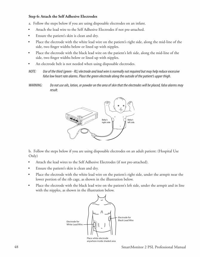
48 SmartMonitor 2 PSL Professional Manual
Step 6: Attach the Self Adhesive Electrodes
a.Followthestepsbelowifyouareusingdisposableelectrodesonaninfant.• AttachtheleadwiretotheSelfAdhesiveElectrodesifnotpre-attached.• Ensurethepatient’sskiniscleananddry.• Placetheelectrodewiththewhiteleadwireonthepatient’srightside,alongthemid-lineofthe
side,twofingerwidthsbeloworlinedupwithnipples.• Placetheelectrodewiththeblackleadwireonthepatient’sleftside,alongthemid-lineofthe
side,twofingerwidthsbeloworlinedupwithnipples.• Anelectrodebeltisnotneededwhenusingdisposableelectrodes.
NOTE: Use of the third (green - RL) electrode and lead wire is normally not required but may help reduce excessive false low heart rate alarms. Place the green electrode along the outside of the patient’s upper thigh.
WARNING: Do not use oils, lotion, or powder on the area of skin that the electrodes will be placed, false alarms may result.
SpO2
%% Baby’s
right sideBaby’sleft side
b.Followthestepsbelowifyouareusingdisposableelectrodesonanadultpatient:(HospitalUseOnly)• AttachtheleadwirestotheSelfAdhesiveElectrodes(ifnotpre-attached).• Ensurethepatient’sskiniscleananddry.• Placetheelectrodewiththewhiteleadwireonthepatient’srightside,underthearmpitnearthe
lowerportionoftheribcage,asshownintheillustrationbelow.• Placetheelectrodewiththeblackleadwireonthepatient’sleftside,underthearmpitandinline
withthenipples,asshownintheillustrationbelow.
Electrode forWhite Lead Wire
Electrode forBlack Lead Wire
Place white electrodeanywhere inside shaded area
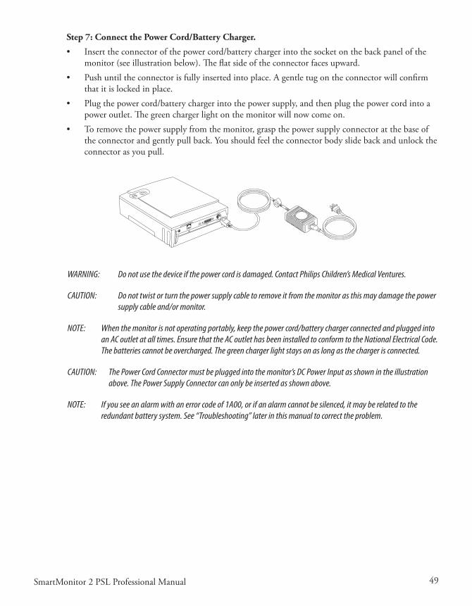
49SmartMonitor 2 PSL Professional Manual
Step 7: Connect the Power Cord/Battery Charger.
• Inserttheconnectorofthepowercord/batterychargerintothesocketonthebackpanelofthemonitor(seeillustrationbelow).Theflatsideoftheconnectorfacesupward.
• Pushuntiltheconnectorisfullyinsertedintoplace.Agentletugontheconnectorwillconfirmthatitislockedinplace.
• Plugthepowercord/batterychargerintothepowersupply,andthenplugthepowercordintoapoweroutlet.Thegreenchargerlightonthemonitorwillnowcomeon.
• Toremovethepowersupplyfromthemonitor,graspthepowersupplyconnectoratthebaseoftheconnectorandgentlypullback.Youshouldfeeltheconnectorbodyslidebackandunlocktheconnectorasyoupull.
WARNING: Do not use the device if the power cord is damaged. Contact Philips Children’s Medical Ventures.
CAUTION: Do not twist or turn the power supply cable to remove it from the monitor as this may damage the power supply cable and/or monitor.
NOTE: When the monitor is not operating portably, keep the power cord/battery charger connected and plugged into an AC outlet at all times. Ensure that the AC outlet has been installed to conform to the National Electrical Code. The batteries cannot be overcharged. The green charger light stays on as long as the charger is connected.
CAUTION: The Power Cord Connector must be plugged into the monitor’s DC Power Input as shown in the illustration above. The Power Supply Connector can only be inserted as shown above.
NOTE: If you see an alarm with an error code of 1A00, or if an alarm cannot be silenced, it may be related to the redundant battery system. See “Troubleshooting” later in this manual to correct the problem.

50 SmartMonitor 2 PSL Professional Manual

51SmartMonitor 2 PSL Professional Manual
hospITal Mode
Themonitor’sHospitalModeControlparameterissettoNOwhenitcomesfromthefactory.ThiscontrolenablesthefeaturesofHospitalMode,specifically:• eliminationofthesiblingprotectionmechanism• silencealarmfeatureforpatientalarms• alarmsetpointreviewatpoweron.
Tomakechangestothisparameter,refertothesection“SystemSetupMenu”earlierinthismanual.
Ifthemonitorisgoingtobeusedinahomesetting,makesurethattheHospitalModeControlparameterissettoNO.
NOTE: Monitors equipped with the Hospital Alarm feature will have the parameter set to YES when they come from the factory.

52 SmartMonitor 2 PSL Professional Manual

53SmartMonitor 2 PSL Professional Manual
respondIng To alarMs
paTIenT alarM
APatientAlarmindicatesthatthepatient’sbreathing,heartactivityoroxygensaturationisoutsidethelimitsprescribedbythephysician.Theinformationinthissectioncanhelpyourespondappropriatelytopatientalarms.Readthissectioncarefully.Ifyouhaveanyquestions,pleasecontactPhilipsChil-dren’sMedicalVentures.
TesTIng The alarM
Beforeyouusethemonitor,testtodetermineifyoucanhearthealarmfromdifferentroomswhilethereisnoiseinthehouse.
CAUTION: Be aware that the alarm sound is very loud. Do not place the monitor in the bed with the patient or direct the speaker toward the patient.
• Alwayskeeptheareainfrontofthespeakerclear.• Turnthemonitoron(withoutthepatientattached)tosoundthealarm.Makesureyoucanhear
thealarmindifferentareasinthehome.
SmartMonitor PSL
Speaker
NOTE: The monitor contains multiple buzzers and alarm sounds. If a buzzer/alarm sound changes or no longer func-tions, contact your home care provider immediately.
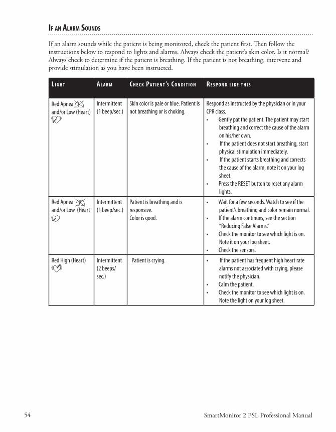
54 SmartMonitor 2 PSL Professional Manual
If an alarM sounds
Ifanalarmsoundswhilethepatientisbeingmonitored,checkthepatientfirst.Thenfollowtheinstructionsbelowtorespondtolightsandalarms.Alwayscheckthepatient’sskincolor.Isitnormal?Alwayschecktodetermineifthepatientisbreathing.Ifthepatientisnotbreathing,interveneandprovidestimulationasyouhavebeeninstructed.
l I g h T a l a r M C h e C k pa T I e n T ’s C o n d I T I o n r e s p o n d l I k e T h I s
Red Apnea and/or Low (Heart)
Intermittent (1 beep/sec.)
Skin color is pale or blue. Patient is not breathing or is choking.
Respond as instructed by the physician or in your CPR class. • Gently pat the patient. The patient may start
breathing and correct the cause of the alarm on his/her own.
• If the patient does not start breathing, start physical stimulation immediately.
• If the patient starts breathing and corrects the cause of the alarm, note it on your log sheet.
• Press the RESET button to reset any alarm lights.
Red Apnea and/or Low (Heart
Intermittent (1 beep/sec.)
Patient is breathing and is responsive. Color is good.
• Wait for a few seconds. Watch to see if the patient’s breathing and color remain normal.
• If the alarm continues, see the section “Reducing False Alarms.”
• Check the monitor to see which light is on. Note it on your log sheet.
• Check the sensors.
Red High (Heart) Intermittent (2 beeps/sec.)
Patient is crying. • If the patient has frequent high heart rate alarms not associated with crying, please notify the physician.
• Calm the patient.• Check the monitor to see which light is on.
Note the light on your log sheet.
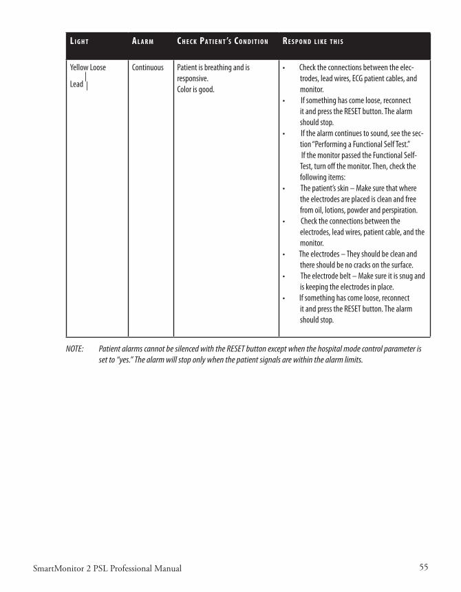
55SmartMonitor 2 PSL Professional Manual
l I g h T a l a r M C h e C k pa T I e n T ’s C o n d I T I o n r e s p o n d l I k e T h I s
Yellow Loose
Lead
Continuous Patient is breathing and is responsive.Color is good.
• Check the connections between the elec-trodes, lead wires, ECG patient cables, and monitor.
• If something has come loose, reconnect it and press the RESET button. The alarm should stop.
• If the alarm continues to sound, see the sec-tion “Performing a Functional Self Test.”
If the monitor passed the Functional Self-Test, turn off the monitor. Then, check the following items:
• The patient’s skin – Make sure that where the electrodes are placed is clean and free from oil, lotions, powder and perspiration.
• Check the connections between the electrodes, lead wires, patient cable, and the monitor.
• The electrodes – They should be clean and there should be no cracks on the surface.
• The electrode belt – Make sure it is snug and is keeping the electrodes in place.
• If something has come loose, reconnect it and press the RESET button. The alarm should stop.
NOTE: Patient alarms cannot be silenced with the RESET button except when the hospital mode control parameter is set to “yes.” The alarm will stop only when the patient signals are within the alarm limits.

56 SmartMonitor 2 PSL Professional Manual
respondIng To sysTeM alarMs
ASystemAlarmindicatesthatthemonitormaynotbefunctioningproperlyoratoptimumcapacity.Theinformationinthissectionwillhelpyourespondappropriatelytosystemalarms.Whenasystemalarmoccurs,oneofthelightsatthebottomofthefrontpanelwillcomeon.
I f T h I s l I g h T I s o n a n d T h I s C o n d I T I o n e x I s T s I T M e a n s.. .
Power Continuous green light, no alarm. Normal Operation. The green power indicator light will come on and stay on for as long as the monitor is on.
Charger Continuous or blinking green light, no alarm.
Normal Operation. The green charger light will come on and blink when the battery is charging and stay on when the battery is fully charged while the battery charger is plugged into an active outlet and connected to the monitor.
Low Battery Flashing yellow light, continuous alarm.
Continuous yellow light, continuous alarm.
This is a warning that the battery voltage is very low and should be recharged soon. (See the section “Charging the Monitor’s Battery” later in this manual.) Press the RESET button to temporarily silence the alarm. The alarm will resound in 2 minutes if the monitor has not been plugged in. The yellow light will continue to flash.
This is a warning that the battery is too low for the moni-tor to operate properly. The monitor must be recharged. Turn the monitor off. Then, recharge the battery. (See “Charging the Battery” in this manual).If you do not recharge the battery, the system will auto-matically shut down.
Memory Full Flashing yellow light, continuous alarm.
Flashing yellow light, no alarm.
When the monitor’s Memory Almost full parameter is reached, the Memory Full light will flash. The alarm will sound continuously. The alarm will sound only if the monitor has been programmed to do so at the 50% full or at 80% full. Press the RESET button to silence the alarm. The light will blink every second.
NOTE: Memory Full is a warning condition. You can continue monitoring. However, you should download the memory to resolve the alarm.NOTE: The Memory Full alarm will sound each time the monitor is powered on.

57SmartMonitor 2 PSL Professional Manual
I f T h I s l I g h T I s o n a n d T h I s C o n d I T I o n e x I s T s I T M e a n s.. .
Memory Full Continuous yellow light, continuous alarm.Continuous yellow light, no alarm.
The monitor’s memory is 100% full. Press the RESET but-ton to silence the alarm. The light will stay on continu-ously. You must transfer data when you get a memory 100% full condition. (See “Transferring SmartMonitor 2 PSL Memory” in this manual for more information.)NOTE: The alarm will sound only if the monitor has been programmed to do so.
Loose Lead Continuous yellow light and continuous alarm
The yellow loose lead light and the alarm may sound continuously when there is a problem with any of the following:• Lead wires• Electrodes• Electrode belt• ECG Patient cable, or• Connections between the patient’s skin and the electrodes, the lead wires, the patient cable(s), and the monitor.
Loose Lead Continuous yellow light and no alarm If you correct the problem, the alarm will stop. However,
the yellow light remains on until you press the RESET button.
Power Continuous green light, continuous alarm, with no other lights lit.
Check the bottom panel display for error messages. If no error messages are displayed, the monitor was turned off improperly causing a sibling alarm.To resolve:Press and hold the blue RESET button.Press and release the gray POWER button.Wait two seconds then release the RESET button.
All All lights are blinking and the alarm will come on for three seconds and then off for one second.
Check the bottom LCD display for error messages. If there is an error message, enter it on your log sheet.Turn the monitor off and then back on. If the monitor functions normally continue to use the monitor. If not contact Philips Children’s Medical Ventures for service.
NOTE: When the Hospital Mode Control parameter is set to YES, the Silence Alarm feature is enabled. This allows the user to silence the audible alarm for 60 seconds when the alarm is being caused by a physiologic event(s). The user can silence the alarm by pressing the RESET button. If the physiologic event(s) is still active after 60 second(s), the alarm will sound again. This feature only affects the audible portion of the alarm. The front panel indicators are not affected.

58 SmartMonitor 2 PSL Professional Manual
reduCIng false alarMs
Properelectrodeplacementwillminimizefalsealarms.• Makesuretheelectrodesareplacedalongthemid-lineoftheside,twofingerwidthsbelowor
linedupwiththenipples.• IfusingtheblackreusableelectrodeswiththeVelcrobelt,ensurethebeltisquitesnug.Placethe
electrodes far enough apart so that when the belt is wrapped around the patient, the electrode will belocatedalongthemid-lineoftheside,twofingerwidthsbeloworlinedupwiththenipples.
• Theskinshouldbecleananddry.Iftheskinisunusuallydry,youmayaddafewdropsofmois-ture(water)tothepatient’sskinpriortoelectrodebeltplacement.
• Whenusingtheblackreusableelectrodes,ensurethattheelectrodesurfaceisclean.• Useofthethird(green-RL)electrodeandleadwireisnormallynotrequired,butmayhelp
reduceexcessivefalselowheartratealarms.Placethegreenelectrodealongtheoutsideofpatient’supperthigh.
NOTE: Refer to the Synergy-E Manual for more information on how to check signal quality using a modem or using a direct-connect cable.

59SmartMonitor 2 PSL Professional Manual
MonITorIng
TurnIng The MonITor on
Afteryouhaveproperlysetupthemonitor,andlearnedhowthemonitorfunctionsandhowtore-spondtoalarms,youcanbeginmonitoringthepatient’sbreathingandheartactivityaccordingtothescheduleprescribedbythephysician.
PushthePOWERbutton.Themonitorperformsasystemcheck.Thelightsonthefrontofthemoni-torwillcomeonbrieflyandtheaudiblealarmwillbeeptwice.Within10seconds,thegreenrespira-tionandheartlightswillbegintoblink.Ifthelightsdonotblink,checkthatyouhaveattachedtheelectrode belt or electrodes properly to the patient, the lead wires are pushed in, and that cables are connected.Oncethepatientisproperlyconnectedtothemonitorandthepowerison,thefollowingshould occur:• Thegreen(battery)chargerlightison(ifthemonitorispluggedintoanACoutlet).• Thegreenpowerlightison.• Thegreenrespirationlightandgreenheartlightareblinking.• Allotherlightsshouldbeoff.• Ifthelightsdonotblink,refertothestepsfoundin“HomeSetup”earlierinthismanual.Besure
youhavefollowedallinstructions.
NOTE: If the Hospital Mode Control and front panel parameter are set to YES, then each of the following will appear briefly on the front panel display during startup:
• Afterallthelightshaveturnedonandtheaudiblealarmhassoundedbriefly,theApneaAlarmLEDwilllightupandvalueoftheApneaSystemparameterwillappearaboveBrPMonthefrontpaneldisplay(infantsonly).
• TheBradycardia(lowheartrate)AlarmLEDwilllightupandthevalueoftheBradycardiaSys-temParameterwillappearaboveBPMonthefrontpaneldisplay.
• TheTachycardia(highheartrate)AlarmLEDwilllightupandthevalueoftheTachycardiaSys-temParameterwillappearaboveBPMonthefrontpaneldisplay.
TurnIng The MonITor off - sIblIng alarM
TheSmartMonitor2PSLhasabuilt-insafetyfeaturecalledasiblingalarm.Ifthemonitorisnotturnedoffinaspecificsequence,thegreenpowerlightwillremainonandthealarmwillsoundcon-tinuously.Thissafetyfeaturemakessurethepowerisnotaccidentallyturnedoff.Toturnthemonitoroff:• PressandholdtheblueRESETbutton.• PressandreleasethegrayPOWERbutton.
• Wait2seconds,andthenreleasetheRESETbutton.

60 SmartMonitor 2 PSL Professional Manual
WhenthemonitoristurnedoffwithoutpushingtheRESETbuttonfirst,thegreenpowerlightwillremainonandtheSiblingAlarmwillsound.TosilencetheSiblingAlarm:• PressandholdtheblueRESETbutton.• PressandreleasethegrayPOWERbutton.• Wait2seconds,andthenreleasetheRESETbutton.• Toresumemonitoring,pressthegrayPOWERbutton.
NOTE: If the Hospital Mode Control parameter is set to YES, then the Sibling Alarm feature is disabled. You may turn the monitor on and off by pressing the POWER button.
Ifthereisaninternalsoftwareerror,aspecialpoweroffprocedureisrequired.• PressandholdtheRESETbutton.WhilestillholdingdowntheRESETbutton,pressandhold
thePOWERbutton.Holdbothbuttonsdownfor5seconds.
• ReleasePOWERbutton;continuetoholdtheRESETbuttonuntilthemonitorturnsoff.
MonITorIng breaThIng
respIraTIon lIghT/dIsplay
Thegreenrespirationlightwillblinkinrhythmwitheachbreaththatthemonitordetects.Thelightshouldblinkonlyonceforeachbreath,althoughitmayflashmoretimeswhenthepatientismoving.
Thepatient’saveragerespirationratewillappearonthefrontpaneldisplayaboveBrPMwhenthedisplayfeatureisenabled.
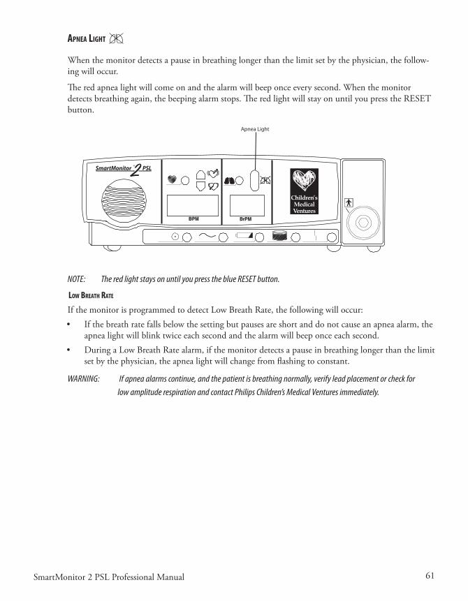
61SmartMonitor 2 PSL Professional Manual
apnea lIghT
When the monitor detects a pause in breathing longer than the limit set by the physician, the follow-ingwilloccur.
Theredapnealightwillcomeonandthealarmwillbeeponceeverysecond.Whenthemonitordetectsbreathingagain,thebeepingalarmstops.TheredlightwillstayonuntilyoupresstheRESETbutton.
NOTE: The red light stays on until you press the blue RESET button.
loW breaTh raTe
IfthemonitorisprogrammedtodetectLowBreathRate,thefollowingwilloccur:• Ifthebreathratefallsbelowthesettingbutpausesareshortanddonotcauseanapneaalarm,the
apnealightwillblinktwiceeachsecondandthealarmwillbeeponceeachsecond.• DuringaLowBreathRatealarm,ifthemonitordetectsapauseinbreathinglongerthanthelimit
setbythephysician,theapnealightwillchangefromflashingtoconstant.
WARNING: If apnea alarms continue, and the patient is breathing normally, verify lead placement or check for low amplitude respiration and contact Philips Children’s Medical Ventures immediately.
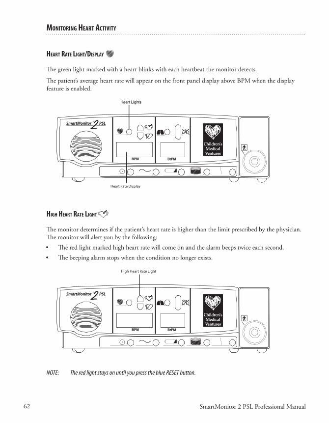
62 SmartMonitor 2 PSL Professional Manual
MonITorIng hearT aCTIvITy
hearT raTe lIghT/dIsplay
Thegreenlightmarkedwithaheartblinkswitheachheartbeatthemonitordetects.
Thepatient’saverageheartratewillappearonthefrontpaneldisplayaboveBPMwhenthedisplayfeatureisenabled.
hIgh hearT raTe lIghT
Themonitordeterminesifthepatient’sheartrateishigherthanthelimitprescribedbythephysician.The monitor will alert you by the following:• Theredlightmarkedhighheartratewillcomeonandthealarmbeepstwiceeachsecond.• Thebeepingalarmstopswhentheconditionnolongerexists.
NOTE: The red light stays on until you press the blue RESET button.

63SmartMonitor 2 PSL Professional Manual
loW hearT raTe lIghT
Whenthemonitordeterminesthatthepatient’sheartrateislowerthanthelimitprescribedbythephysician, the following will happen:• Theredlightmarkedlowheartratewillcomeon.• Thealarmbeepsonceeverysecond.• Thebeepingalarmstopswhentheconditionnolongerexists.
NOTE: The red light stays on until you press the blue RESET button.

64 SmartMonitor 2 PSL Professional Manual

65SmartMonitor 2 PSL Professional Manual
porTable operaTIon of The sMarTMonITor 2 pslThemonitorisdesignedforportableuse.Whenthepowercordisnotused,themonitorreliesonapreviouslychargedinternalbatteryforpower.
PhilipsChildren’sMedicalVenturesrecommendsthatthemonitorbeusedwiththepowercord/bat-terychargerwheneverpossible.However,whenthemonitorisusedwithoutthepowercord/batterychargerthemonitorisfullyfunctional.Allalarmsareoperational.Withafullychargedbattery,themonitorwillrunfor15hourswiththeoximeteroff.Pleasenotethatthefrontpaneldisplay(ifen-abled) will be dimmed to conserve battery life, and you will not be able to adjust the brightness in this mode.Theamountoftimetocompletelyrechargeafullydepletedbatteryis8hours.
SmartMonitor2PSLincludesaredundantbatterysystem.ArechargeablebatterypackandtwoAAAalkalinebatteriesarelocatedinthebatterycompartment.Ifthereisafailureintherechargeablepack,theAAAbatteriesgenerateanalarm.Iftherechargeablepackisnearlycompletelydischarged,thealarmwillalsosound.Thismayoccurwhenthebatterypackisfirstinstalledinanewmonitororifamonitorisunusedfortwomonthsorlonger.Alwaysunplugthebatterypackcableisyouarenotgo-ingtousethemonitorforanextendedperiodoftime.Thispreventsunnecessaryalarmsuponfuturereconnection.
ChargIng The MonITor’s baTTery
Asarule,afullychargedbatterycanoperatefor15hourswiththeoximeteroff.Thismayvary,how-ever,dependingonthelevelofuse,numberofalarms,andotherfactors.Whenthelowbatterylightcomeson,youshouldrechargethebatteryimmediately.Afullydrainedbatteryshouldberechargedfor8hours.Whenyouneedtorechargethemonitor’sbattery,followthestepsbelow.• Inserttheconnectorofthepowersupplyintothesocketonthebackpanelofthemonitor.(See
illustrationbelow.)Theflatsideoftheconnectorfacesupward.• Pushuntiltheconnectorisfullyinsertedintoplace.Agentletugontheconnectorwillconfirm
thatitislockedinplace.• Plugthepowercord/batteryintoapoweroutlet.• Thegreenchargerlightcomesonsolidifthebatteryisfullychargedorblinkswhenthebatteryis
charging.• Ifthemonitoristurnedon,theyellowlowbatterylightblinksuntiltheminimumchargelevelis
reached.Then,theyellowlightgoesoff• Toremovethepowersupplyfromthemonitor,graspthepowersupplyconnectoratthebaseof
theconnectorandgentlypullback.Youshouldfeeltheconnectorbodyslidebackandunlocktheconnectorasyoupull.

66 SmartMonitor 2 PSL Professional Manual
NOTE: Fully drained batteries need about 8 hours to recharge.
sMarTMonITor 2 psl baTTery paCk
Warnings
• Neverchangethebatterypackwhilethepowersupplyispluggedinand/orthemonitorisbeingoperated.
• Donotdisassemblethebatterypackorbatteries.Thebatteriescontainelectrolytes,whichcancauseinjurytoeyes,skin,andclothing.
• Donotdisposeoftheoldbatteryinfireorincinerator.Thebatterypackcontainsingredientsthatcouldbeexplosiveandcauseseriouspersonalinjury.
• Donotdisassembleormodifythebattery.Thebatterycontainssafetyandprotectiondevicesthat,ifdamaged,maycausethebatterytoheat,rupture,orignite.
Cautions
• Thebatterypackhasalockingconnector.Donotattempttoremovethebatterypackwithoutreleasingthelatchontheconnector.Doingsowilldamagethebatterywires.
• UseonlyPhilipsChildren’sMedicalVentures-suppliedbatterypacks.Useofotherbatterypackscouldcausemalfunction.
• Whenthebatteryiswornout,insulatetheterminalswithadhesivetapeorsimilarmaterialsbeforedisposal.
baTTery InsTallaTIon InsTruCTIons
Themonitorusestwotypesofbatteries.Rechargeablebatteriesareusedforpowerduringportableoperation.Alkalinebatteriesprovideaback-upalarmfunctioniftherechargeablebatteriesfail.Therechargeablebatteriesarecontainedinsideabatterypack.Twoalkaline,sizeAAA,batteriesareplacedintoaAAAholderlocatedonthesideoftherechargeablepack.
NOTE: Before installing a new or replacement battery pack, write the installation date on the label provided on the battery pack.
1. Turnthemonitors’poweroffusingthecorrectPower-offprocedure,andunplugtheexternalpowersupplyfromthemonitor.
2. Loosen(counterclock-wise)bothscrewsfromthebatterypackcoverandremovethecover.3. Toremovethebatterypack,pullfirmlyupwardwhenliftingthebatterypackout.Disconnect
the battery pack by pressing the latch on the black connector, which is located in the upper left corner.Safelydisposeofalloldbatteriesinaccordancewithyourarea’senvironmentallaws.
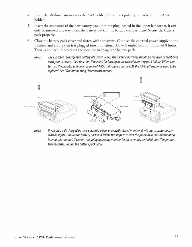
67SmartMonitor 2 PSL Professional Manual
4. InsertthealkalinebatteriesintotheAAAholder.ThecorrectpolarityismarkedontheAAAholder.
5. Inserttheconnectorofthenewbatterypackintothepluglocatedintheupperleftcorner.Itcanonlybeinsertedoneway.Placethebatterypackinthebatterycompartment.Securethebatterypackproperly.
6. Closethebatterypackcoverandfastenwiththescrews.ConnecttheexternalpowersupplytothemonitorandensurethatitispluggedintoafunctionalACwalloutletforaminimumof8hours.Thereisnoneedtopoweronthemonitortochargethebatterypack.
NOTE: The expected rechargeable battery life is two years. The alkaline batteries should be replaced at least once each year to ensure their function, if needed, for backup in the case of a battery pack failure. When you turn on the monitor and an error code of 1A00 is displayed on the LCD, the AAA batteries may need to be replaced. See “Troubleshooting” later in this manual.
Battery Pack Cover
Battery Pack
AA Batteries
Installation Date Label
Cover
Battery
NOTE: If you plug a discharged battery pack into a new or recently stored monitor, it will alarm continuously with no lights. Unplug the battery pack and follow the steps to correct the problem in “Troubleshooting” later in this manual. If you are not going to use the monitor for an extended period of time (longer than two months), unplug the battery pack cable.

68 SmartMonitor 2 PSL Professional Manual

69SmartMonitor 2 PSL Professional Manual
TransferrIng sMarTMonITor 2 psl InforMaTIon
The monitor contains a memory system that automatically records information about each monitor-ingsession.Thisinformationcanbetransferred(ordownloaded)toacomputertobereviewedbythephysician.Thereareseveraldifferentwaystotransferthisinformation.
Whatevermethodyouuse,youmusttransferdatawhenyougetamemory100%fullcondition.Ad-ditionally, you may choose to transfer data at any time or whenever it is considered necessary by the physician.
MeMory ManageMenT In The MonITor
WhendataissuccessfullytransferredtoaMemoryCardordownloadedtoSynergy-E,thedataap-pearstobeerasedinthemonitor.Itnolongercountstowardthereadingof“PercentMemoryFull”ontheLCDorinSynergy-E.Becauseofthismemorymanagementsystem,itisnotnecessarytoerasethememoryaftereverydownload.ShouldadatafilebecomecorruptedorlostonthePCrunningSynergy-E,thedatamaystillberecoveredfromthemonitor.ThedatacanberecoveredusingSynergy-Euntilthemonitorhascollectednewdataandneedsthespaceoccupiedbytheolddata.
Itisrecommendedthatyouerasethememorybetweeneachpatientuse.Pleasenotethatthisfeaturewillnotclearthesystemparametersettings(alarmandrecordlimits)orthepatientnameandIDnumber.
Usingthe“ClearMemory”functionintheSystemParametersmenuswillerasealldataregardlessofwhetherornotithasbeendownloaded.
To reCover The old daTa usIng a MeMory Card
Transferthedatatothecardusingthemonitor.NowimportthecardintoSynergy-E.Whenprompt-edwith“Onlyobtaindatanotpreviouslyretrieved?”,answerNOtoobtainalldata.Synergy-Ewillthendisplayallthedatathatwasinthemonitor.
To reCover The old daTa by doWnloadIng usIng synergy-e
CleartheCheckboxinthemonitorcommunicationsscreenwhichreads,“Onlyretrievedatanotpre-viouslydownloaded?”.Synergy-Ewillthendisplayallthedatathatwasinthemonitor.
ModeM doWnload
NOTE: The monitor must be plugged into the electrical outlet during modem downloads.
Therearethreewaystodownloadwithamodem.Thefirstchoiceinvolvesthemodemautomaticallycallingthehomecaredealer.ThisiscalledModemAutoDial.Thisdoesn’tinvolveanyactiononthecaregivers’part.Itisimportanttoknowthatthemodeminsidetheunitmayusethephoneline.Ifyouaregoingtousethisfeature,youshouldgivemorespecificinstructionstothecaregiver.
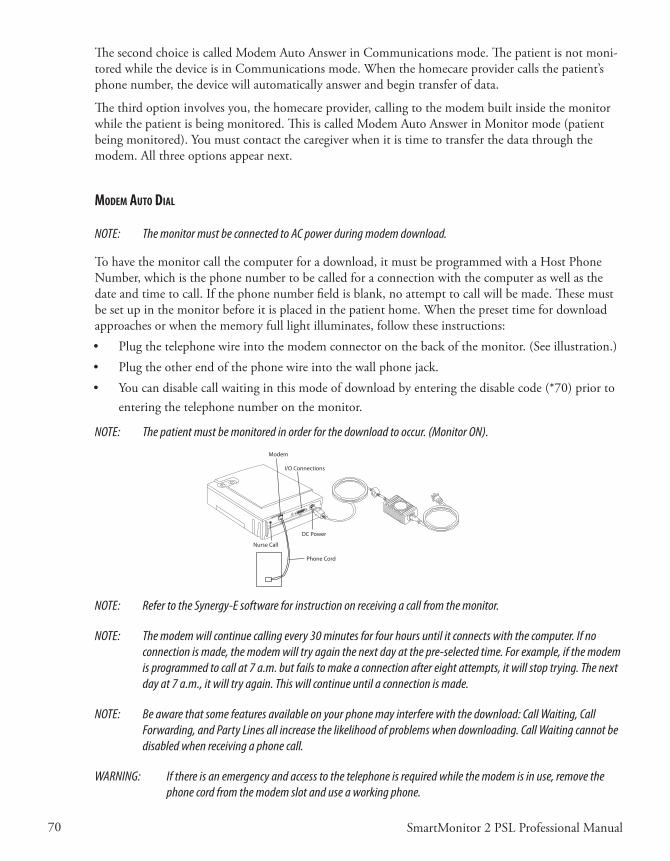
70 SmartMonitor 2 PSL Professional Manual
ThesecondchoiceiscalledModemAutoAnswerinCommunicationsmode.Thepatientisnotmoni-toredwhilethedeviceisinCommunicationsmode.Whenthehomecareprovidercallsthepatient’sphonenumber,thedevicewillautomaticallyanswerandbegintransferofdata.
The third option involves you, the homecare provider, calling to the modem built inside the monitor whilethepatientisbeingmonitored.ThisiscalledModemAutoAnswerinMonitormode(patientbeingmonitored).Youmustcontactthecaregiverwhenitistimetotransferthedatathroughthemodem.Allthreeoptionsappearnext.
ModeM auTo dIal
NOTE: The monitor must be connected to AC power during modem download.
Tohavethemonitorcallthecomputerforadownload,itmustbeprogrammedwithaHostPhoneNumber,whichisthephonenumbertobecalledforaconnectionwiththecomputeraswellasthedateandtimetocall.Ifthephonenumberfieldisblank,noattempttocallwillbemade.Thesemustbesetupinthemonitorbeforeitisplacedinthepatienthome.Whenthepresettimefordownloadapproaches or when the memory full light illuminates, follow these instructions: • Plugthetelephonewireintothemodemconnectoronthebackofthemonitor.(Seeillustration.)• Plugtheotherendofthephonewireintothewallphonejack.• Youcandisablecallwaitinginthismodeofdownloadbyenteringthedisablecode(*70)priorto
enteringthetelephonenumberonthemonitor.
NOTE: The patient must be monitored in order for the download to occur. (Monitor ON).
Phone Cord
Modem
I/O Connections
DC Power
Nurse Call
NOTE: Refer to the Synergy-E software for instruction on receiving a call from the monitor.
NOTE: The modem will continue calling every 30 minutes for four hours until it connects with the computer. If no connection is made, the modem will try again the next day at the pre-selected time. For example, if the modem is programmed to call at 7 a.m. but fails to make a connection after eight attempts, it will stop trying. The next day at 7 a.m., it will try again. This will continue until a connection is made.
NOTE: Be aware that some features available on your phone may interfere with the download: Call Waiting, Call Forwarding, and Party Lines all increase the likelihood of problems when downloading. Call Waiting cannot be disabled when receiving a phone call.
WARNING: If there is an emergency and access to the telephone is required while the modem is in use, remove the phone cord from the modem slot and use a working phone.

71SmartMonitor 2 PSL Professional Manual
ModeM auTo ansWer In CoMMunICaTIons Mode
ThemonitormustbeconnectedtoACpowerduringmodemdownload.1. Connectaphonecordfromthewalljacktothemodemconnectoronthebackofthemonitor.2. Toallowthemonitortoworkwiththemodem,placethemonitorinCommunicationsMode:
• PressandreleasethePOWERbuttontoturnthemonitoron.• PressandholdtheblueRESETbutton.• Waituntilthemonitoralarms.• ReleasetheRESETbutton.BrieflypressandreleasetheRESETbuttonagain.Themonitor’s
bottomdisplaywillread“CommunicationModeisNowActive.”
Themonitorbeepsevery10secondswheneveritisintheCommunicationsMode.Thisisareminderthatthemonitorispoweredonforworkingwiththecomputer,MemoryCard,ormo-dem,butnotformonitoringthepatient.
DonotconnectthepatienttothemonitorwhenintheCommunicationsMode;theapneaandheartratealarmsarenotoperationalinthismode.• Thehomecareprovidershouldnowcalltoretrievetheinformation.Thephonemayring,
butdonotanswer.Themodemanswersthecallandconnectsthemonitortothecomputerthroughthephoneline.
3. Theamountoftimetotransfertheinformationwillvary.Whenthetransferiscompletethemonitorwillbeepfivetimes.Afterthetransfer,youmaydisconnectthephonelinefromthemonitorandthephonewillworknormally.Turnthemonitoroffinthenormalway.• PressandholdtheblueRESETbutton.• PressandreleasethegrayPOWERbutton.• Waittwoseconds,andthenreleasetheRESETbutton.• Youcannowresumemonitoringthepatient.
NOTE: Be aware that some features available on your phone may interfere with the download: Call Waiting, Call Forwarding, and Party Lines all increase the likelihood of problems when downloading. Call Waiting cannot be disabled when receiving a phone call.
ModeM auTo ansWer In MonITor Mode
ThemonitormustbeconnectedtoACpowerduringmodemdownload.1. Connectaphonecordfromthewalljacktothemodemconnectoronthebackofthemonitor.2. Toallowthemonitortoworkwiththemodemwhenthemonitorisinmonitormode(thepa-
tient is being monitored):• Whenthehomecareprovidercallsforadownloadandthephonerings,thecaregivershould
pressandholddowntheblueRESETbuttonuntilthephonestopsringing.• Thisindicatesthatthemonitorhasansweredthecall.
3. ThehomecareproviderwillnowusetheSynergy-Esoftwaretotransferthemonitorinformation.

72 SmartMonitor 2 PSL Professional Manual
NOTE: If there is an emergency and access to the telephone is required while the modem is in use, remove the phone cord from the modem slot and use a working phone.
4. Theamountoftimetotransfertheinformationwillvary.Whenthetransferiscompletethemonitorwillbeepfivetimes.Afterthetransfer,disconnectthephonelinefromthemonitorandthephonewillworknormally.
NOTE: Be aware that some features available on your phone may interfere with the download: Call Waiting, Call Forwarding, and Party Lines all increase the likelihood of problems when downloading. Call Waiting cannot be disabled when receiving a phone call.
TransferrIng MonITor daTa To a MeMory Card
TheMemoryCardisacredit-card-sizedelectronicmemorytransferdevicethattransfersmonitordata.Thisisanoptionalfeatureofmonitorandmaynotbeinstalledoneveryunit.
NOTE: You may also use a compact flash card with a Memory Card adapter.
NOTE: All data in the Memory Card at the time of a download will be overwritten. For more information, refer to the section “Setting Alarms and Recording Limits” earlier in this manual.
WhenyouarereadytousetheMemoryCardtotransfermonitordata,followthestepsbelow:1. Makesurethemonitorisoff.2. WiththeMemoryCardlabelfacingyou,slidethecardintotheslotprovidedonthesidepanelof
themonitor.ThelocationoftheMemoryCardlogowillbeonthebottomedgeandfacingyou.
enterenter
Push button toremove Memory Card
3. PressthePOWERbuttonON.Afterashortdelay,thedisplaywillread:INITIALIZINGPLEASEWAITThen,MENUMODE?ENTERPROPERKEYSEQUENCE
4. PresstheENTERbuttonwithin10seconds.ThedisplaywillreadSMARTMONITOR2MENUSELECTION.
5. Pressthe arrowuntilyousee“MoveDataToCard?”

73SmartMonitor 2 PSL Professional Manual
6. PresstheENTERbutton.ThewordNOwillbegintoblink.ToselectYES,presseitherarrowbutton.
7. PresstheENTERbutton.Thedisplaywillnowshow“TransferringData…”Oncethetransferiscomplete,thedisplaywillchangeto“DataTransferred.”
Ifthecardhasdataonit,thefollowingisdisplayedaftersteps1-6.• Thedisplaymayshow“CardFull-Overwrite?”• PresstheENTERbutton.ThewordNOwillbegintoblink.ToselectYESpresseitherarrowbut-
ton.• PresstheENTERbutton.Thedisplaywillnowshow“TransferringData…”Oncethetransferis
completethedisplaywillchangeto“DataTransferred.”
Release Button
Memory Display Detail
NOTE: The memory in the monitor will not be automatically cleared. The recorded data in the monitor will be “Flagged” as downloaded information and, if it is not cleared before the next download, the Synergy-E soft-ware will exclude those duplicated events. Synergy-E has the ability to retrieve all the data if desired. Refer to the Synergy-E Manual for more information.
TransferrIng MonITor daTa usIng a CoMpuTer
Datacanbedownloadedfromthemonitorbydirectconnectiontoacomputer.
TheSynergy-Esoftwareisrequiredtodownloadthemonitor.
ThemonitorcanbeplacedinCommunicationModeorMonitoringMode.IfMonitoringModeischosen,allalarmsandrecordparametersarefunctional.
CoMMunICaTIons Mode seTup
The download cable must be connected to the monitor and the computer before turning the monitor on.• ConnectthedownloadcabletotheI/OconnectionsportonthemonitorandtheCOMPorton
thecomputer.• ThemonitorcanbeplacedinCommunicationsMode.

74 SmartMonitor 2 PSL Professional Manual
• PressandreleasethePOWERbuttontoturnthemonitoron.• PressandholdtheblueRESETbutton.• Waituntilthemonitoralarmsconstantly.• ReleasetheRESETbutton.BrieflypressandreleasetheRESETbuttonagain.Themonitordisplaywillread“MonitorisinCommunicationMode”.• Themonitorbeepsevery10secondswhenitisintheCommunicationsModebutisnotelec-
tronicallyconnectedorlinkedtoanything.Thisisareminderthatthemonitorispoweredonforworkingwiththecomputer,MemoryCard,ormodembutnotformonitoringthepatient.
NOTE: Refer to the Synergy-E software for instruction on Direct Connection Downloading of the monitor.

75SmartMonitor 2 PSL Professional Manual
CarIng for The sMarTMonITor 2 pslCAUTION: Use the information in this section to keep the monitor functioning well.
CAUTION: Use only Philips Children’s Medical Ventures accessories with the monitor.
CleanIng InsTruCTIons
TurnthemonitorOFF,unplugitfromtheelectricaloutlet,anddisconnectallaccessoriesbeforeyoubegincleaning.
Neverimmersethemonitororanyoftheaccessoriesinwaterorspraycleanerdirectlyonthem.Applywaterorcleanertoasoftclothandgentlywipethecomponentstocleanthem.
MonITor, poWer Cord/baTTery Charger, paTIenT Cables and lead WIres
Useacleanclothandanyofthefollowing:• Unscenteddishwashingdetergent• 3%hydrogenperoxidesolution• 91%Isopropylalcohol• 10%bleachsolution
• GermicidalCloth
eleCTrodes
• Donotattempttocleanthedisposablestyleelectrodes.• Cleanthecarbonelectrodeswithamildsoapandwater.Theymustberinsedwelltoremoveany
tracesofsoapfilm.Soapfilmcanpreventheartandbreathingsignalsfrombeingpickedupclearlybythemonitor.
• Ensurethattheelectrodesarecompletelydrybeforeusing.
sofT CarryIng Case
• Althoughthecarelabelinthecarryingcasesuggestsmachinewashinginwarmwater,theappear-anceofthecarryingcasewillchangenoticeablyafterwashing.
• PhilipsChildren’sMedicalVenturesrecommendsthatyouwipethecasewithadampclothorspongeusingalightdetergent,ifnecessary.Air-dryonly.

76 SmartMonitor 2 PSL Professional Manual
InseCT InfesTaTIon deConTaMInaTIon proCedures
1. FumigatingaRoach/Insect-infestedUnit• PlacetheunitinsideaZip-locktypeplasticbag(i.e.,fruit/vegetablebagorlargefreezerbag).• InsertapeststriporRoachMotelinsidethebagwiththeunit.• Sealthebagtightlyandleaveitatroomtemperatureorwarmerforaminimumof30days.
Duringtheincubationperiod,anyinsecteggsinsidetheunitwillhatch.Consequently,theoffspringwillevacuatetheunitandbekilledbythechemicalsfromthepesticide.
• After30days,removetheunitfromthebag.Disposeofthebagandcleantheunitthorough-lyasdirectedbelow.
2. Cleaningtheunit
WARNING: Never clean the monitor while the monitor is in use or the power supply is plugged into an electrical outlet. Never immerse the unit in water. Do not clean the monitor with rubbing alcohol.
• Aftertheaboveprocedureshavebeencompleted,removethebatteryandopentheunitinanESD-protected(grounded,static-free)area.
• Usingde-ionizedcompressedair/gasdustersuitableforuseonelectronics,blowoutalloftheremainsofanyinsectcontamination.
• Closetheunitandre-installthescrewsandbatterypack.• Useacleanclothwithanunscented,alcohol-freedishwashingdetergentor3%Hydrogen
Peroxidesolutiontocleantheoutsideofthemonitor.• Ifnecessary,returntheunittoPhilipsChildren’sMedicalVenturesforrepair.• Unitsunderwarrantywillnotbechargedforlabor/re-certification,butwillbechargedfor
anydamagedorrepairedcomponents.
perforMIng a funCTIonal self-TesT
Themonitor’sfunctionalself-testchecksthatallthefeaturesoftheunitarefunctioningproperly.Youshould perform a functional self-test at least once a week or according to the instructions given by the healthcareprofessional.Youshouldalsoperformthetest:• afteraleadwireischanged• afterapatientcableischanged.
Toperformthefunctionalself-test,followthestepslistedbelow.
1. InserttheECGpatientcableintothesocketlocatedonthefrontofthemonitor.2. ConnecttheleadwirestotheECGpatientcable.Insertthewhiteleadwireintotheopening
labeledRA.InserttheblackleadwireintotheopeninglabeledLA.3. Connecttheleadwirestothefunctionalself-testsocketonthesidepanelofthemonitor.Insert
thewhiteleadwireintotheRAopeningandthentheblackleadwireintotheLAopening.4. Turnonthemonitor.Youheartwoshortbeepsandthelightsonthefrontcomeonbrieflythen
gooff.
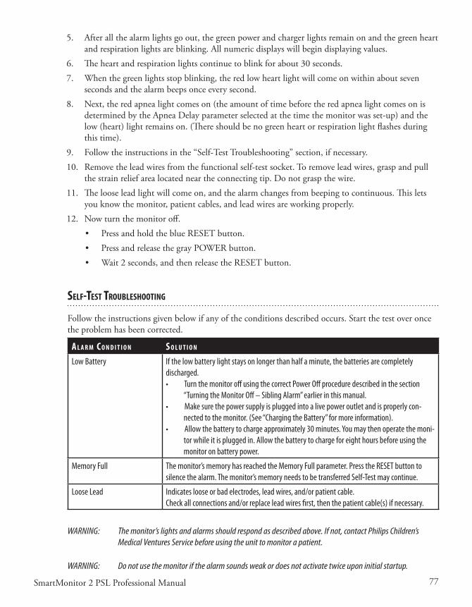
77SmartMonitor 2 PSL Professional Manual
5. Afterallthealarmlightsgoout,thegreenpowerandchargerlightsremainonandthegreenheartandrespirationlightsareblinking.Allnumericdisplayswillbegindisplayingvalues.
6. Theheartandrespirationlightscontinuetoblinkforabout30seconds.7. Whenthegreenlightsstopblinking,theredlowheartlightwillcomeonwithinaboutseven
secondsandthealarmbeepsonceeverysecond.8. Next,theredapnealightcomeson(theamountoftimebeforetheredapnealightcomesonis
determinedbytheApneaDelayparameterselectedatthetimethemonitorwasset-up)andthelow(heart)lightremainson.(Thereshouldbenogreenheartorrespirationlightflashesduringthistime).
9. Followtheinstructionsinthe“Self-TestTroubleshooting”section,ifnecessary.10. Removetheleadwiresfromthefunctionalself-testsocket.Toremoveleadwires,graspandpull
thestrainreliefarealocatedneartheconnectingtip.Donotgraspthewire.11. Thelooseleadlightwillcomeon,andthealarmchangesfrombeepingtocontinuous.Thislets
youknowthemonitor,patientcables,andleadwiresareworkingproperly.12. Nowturnthemonitoroff.
• PressandholdtheblueRESETbutton.• PressandreleasethegrayPOWERbutton.• Wait2seconds,andthenreleasetheRESETbutton.
self-TesT TroubleshooTIng
Followtheinstructionsgivenbelowifanyoftheconditionsdescribedoccurs.Startthetestoveroncetheproblemhasbeencorrected.
a l a r M C o n d I T I o n s o l u T I o n
Low Battery If the low battery light stays on longer than half a minute, the batteries are completely discharged. • Turn the monitor off using the correct Power Off procedure described in the section
“Turning the Monitor Off – Sibling Alarm” earlier in this manual. • Make sure the power supply is plugged into a live power outlet and is properly con-
nected to the monitor. (See “Charging the Battery” for more information).• Allow the battery to charge approximately 30 minutes. You may then operate the moni-
tor while it is plugged in. Allow the battery to charge for eight hours before using the monitor on battery power.
Memory Full The monitor’s memory has reached the Memory Full parameter. Press the RESET button to silence the alarm. The monitor’s memory needs to be transferred Self-Test may continue.
Loose Lead Indicates loose or bad electrodes, lead wires, and/or patient cable.Check all connections and/or replace lead wires first, then the patient cable(s) if necessary.
WARNING: The monitor’s lights and alarms should respond as described above. If not, contact Philips Children’s Medical Ventures Service before using the unit to monitor a patient.
WARNING: Do not use the monitor if the alarm sounds weak or does not activate twice upon initial startup.

78 SmartMonitor 2 PSL Professional Manual

79SmartMonitor 2 PSL Professional Manual
TroubleshooTIng
Whenever a technical problem occurs that the caregiver cannot handle, he or she should contact the dealer.Thecaregivershouldnottrytofixthemonitor.
The table below lists some common problems:
p r o b l e M po s s I b l e C a u s e I n s T r u C T I o n s
Monitor will notturn on
The monitor is disconnected from the power cord/battery charger; batteries are discharged.
No Power at outlet.
Defective power cord/battery charger.
Internal part failure.
Plug the power cord/battery charger into the monitor and outlet.
Locate an outlet with power.
Contact Philips Children’s Medical Ventures.
Contact Philips Children’s Medical Ventures.
All lights will flash together and the alarm will beep in unison with the flashing lights. Pressing RESET will not silence alarm.
0001 displayed on bottom LCD display.
1B01 displayed on bottom LCD display.
Internal error condition was detected by the monitor
or
Battery not connected
or
Internal failure with monitor.
Reduce likelihood of electrostatic discharge around the monitor. or Contact Philips Children’s Medical Ventures
If an Error number is displayed on the LCD (the LCD is located on the bottom of the moni-tor), record this information. Contact Philips Children’s Medical Ventures.
If there is an internal software error, a special power off procedure is required.• Press and hold the RESET button. While
still holding down the RESET button, press and hold the POWER button. Hold both buttons down for five seconds
• Release POWER button; continue to hold the RESET button until the monitor turns off.

80 SmartMonitor 2 PSL Professional Manual
p r o b l e M po s s I b l e C a u s e I n s T r u C T I o n s
1A00 or 1A01 displayed on bottom LCD display.
Problem with AAA batteries; try replacing them.
• Open the battery compartment, unplug the battery pack, and replace the AAA batteries.
• Plug the power supply cable into the monitor and the power supply cord into the AC outlet, then connect the battery pack cable to the monitor.
When you turn the monitor on, the error code should not appear. If these steps do not resolve the problem, contact Philips Children’s Medical Ventures Customer Service.
Alarm Sound Continuous, No Lights
A discharged battery pack is plugged into a new or recently stored monitor (i.e., the monitor has been unused for two months or longer).
NOTE: SmartMonitor 2 PSL includes a redun-dant battery system. There are a rechargeable battery pack and two AAA alkaline cells located in the battery compartment. The purpose of the AAA cells is to generate an alarm if there is a failure in the rechargeable pack (the alarm also sounds when the pack is nearly completely discharged). This can occur when the battery pack is first installed in a new monitor or in a monitor that has been unused for two months or longer.
Follow this sequence of steps exactly:• Unplug the battery pack.• Plug the power supply cable into the
monitor and the power supply cord into the AC outlet.
• Plug the battery pack cable into the monitor.
If the above steps do not resolve the problem, contact Philips Children’s Medical Ventures Customer Service.
NOTE: If you are not going to use the monitor for an extended period of time, unplug the battery pack cable to prevent unnecessary alarms upon reconnection.
Alarm Sound Continuous, No Lights
or
0001 displayed on bottom LCD display.
No power, battery drained or disconnected.
or
Battery not connected.
Ensure battery is connected.
Connect power supply. Use Power-Off to silence alarm. • Press and hold the blue RESET button. • Press and release the gray POWER button.
Wait two seconds, and then release the RESET button.
Prior to use, allow battery to charge ap-proximately 30 minutes. You may then operate the monitor while it is plugged in. Allow the battery to charge for eight hours before using the monitor on battery power.

81SmartMonitor 2 PSL Professional Manual
p r o b l e M po s s I b l e C a u s e I n s T r u C T I o n s
Alarm Sound Continuous, No Lights
Incorrect power-off sequence. • Press the POWER button, and make sure that the power light is illuminated.
• Press and hold the RESET button. Press and release the POWER button. Wait two seconds, then release the RESET button.
Alarm sounds weak or only one alarm tone is heard at Power Up.
Internal part failureorLow battery.
Contact Philips Children’s Medical Ventures.
Charge battery.
Loose leadorLight and front display remains on.
Connections between sensors, electrodes, lead wires, and patient cables are not properly made.
or
Defective lead wires or patient cable(s)
or
Defective electrodesorInternal part failure.
Verify that (a) patient’s skin underneath electrodes is clean,(b) electrodes are clean, and (c) lead wires are fully inserted into the electrodes and ECG patient cable.
Replace lead wires or patient cables and perform Functional Self-Testor
Replace electrodesandContact Philips Children’s Medical Ventures.
Unable to download via modem.
AC power not connected to the monitor
or
The monitor is not connected to phone line or not connected to phone (wall) jackorDevice power off
or
Incorrect modem selection on computer or
Defective power supply, phone cord, or phone splitter.
Plug the monitor into AC power before performing a download, and verify that the charging light is on.orConnect phone line to monitor and to phone (wall) jackorTurn the monitor’s power on, and verify that power light is onor
Verify modem selection on computeror
Replace power supply, replace phone cord, plug phone cord directly into phone (wall) jack.

82 SmartMonitor 2 PSL Professional Manual
p r o b l e M po s s I b l e C a u s e I n s T r u C T I o n s
Unable to communicate by direct connect.
Download cable was not connected to the monitor and the computer prior to turning on the monitor.
Defective host cable.
Incorrect COM port selection on computer.
Connect the download cable to the monitor and the computer before turning the monitor on.
Replace host cable.
Verify COM port selection on computer.

83SmartMonitor 2 PSL Professional Manual
speCIfICaTIons
devICe sIze
Dimensions: 2.25”x7.25”x9.0”(5.72cmx18.42cmx22.86cm)
Weight: 3.0lbs.(1.35kg)
ShippingWeight: 8.5lbs.(3.9kg)
eleCTrICal raTIngs
PowerSupply: 100-240VAC50/60Hz36W
SmartMonitor2PSL:12VDC,3.0Ampsmax.
LiIonRechargeableBatteryPack: 7.4VDC,4.4AHnominal
envIronMenTal CondITIons
OperatingTemperature: 41ºto104ºF(5ºCto40ºC)
OperatingHumidity: 15%to95%RH,non-condensing
StorageTemperature: -4to140ºF(-20ºCto60ºC)
StorageHumidity: 15to95%RH,non-condensing
BatteryChargingTemperature: 50ºto95ºF(10ºCto35ºC)
sTandards CoMplIanCe
This device is designed to conform to the following standards:
IEC60601-1GeneralRequirementsforSafetyofMedicalElectricalEquipment
IEC/EN60601-1-2:2001(2ndEdition)ImmunityforMedicalElectricalEquipment
TheSmartMonitor2PSLsystemisclassifiedasfollows:
Typeofprotectionagainstelectricshock:ClassII/InternallyPowered
Degreeofprotectionagainstelectricshock:TypeBFAppliedPart
Degreeofprotectionagainstingressofwater:IPX1
Modeofoperation:Continuous
dIsposal
Whennecessary,disposeofthemonitorinaccordancewithyourlocalregulations.
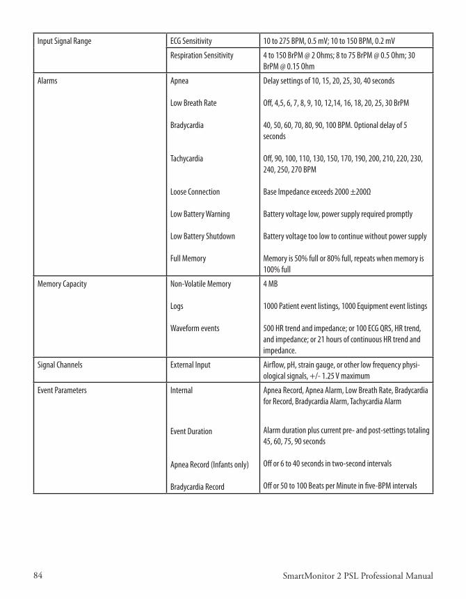
84 SmartMonitor 2 PSL Professional Manual
Input Signal Range ECG Sensitivity 10 to 275 BPM, 0.5 mV; 10 to 150 BPM, 0.2 mV
Respiration Sensitivity 4 to 150 BrPM @ 2 Ohms; 8 to 75 BrPM @ 0.5 Ohm; 30 BrPM @ 0.15 Ohm
Alarms Apnea
Low Breath Rate
Bradycardia
Tachycardia
Loose Connection
Low Battery Warning
Low Battery Shutdown
Full Memory
Delay settings of 10, 15, 20, 25, 30, 40 seconds
Off, 4,5, 6, 7, 8, 9, 10, 12,14, 16, 18, 20, 25, 30 BrPM
40, 50, 60, 70, 80, 90, 100 BPM. Optional delay of 5 seconds
Off, 90, 100, 110, 130, 150, 170, 190, 200, 210, 220, 230, 240, 250, 270 BPM
Base Impedance exceeds 2000 ±200Ω
Battery voltage low, power supply required promptly
Battery voltage too low to continue without power supply
Memory is 50% full or 80% full, repeats when memory is 100% full
Memory Capacity Non-Volatile Memory
Logs
Waveform events
4 MB
1000 Patient event listings, 1000 Equipment event listings
500 HR trend and impedance; or 100 ECG QRS, HR trend, and impedance; or 21 hours of continuous HR trend and impedance.
Signal Channels External Input Airflow, pH, strain gauge, or other low frequency physi-ological signals, +/- 1.25 V maximum
Event Parameters Internal
Event Duration
Apnea Record (Infants only)
Bradycardia Record
Apnea Record, Apnea Alarm, Low Breath Rate, Bradycardia for Record, Bradycardia Alarm, Tachycardia Alarm
Alarm duration plus current pre- and post-settings totaling 45, 60, 75, 90 seconds
Off or 6 to 40 seconds in two-second intervals
Off or 50 to 100 Beats per Minute in five-BPM intervals
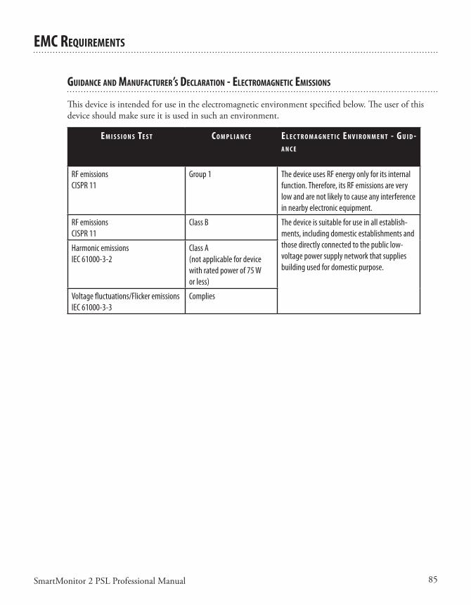
85SmartMonitor 2 PSL Professional Manual
eMC requIreMenTs
guIdanCe and ManufaCTurer’s deClaraTIon - eleCTroMagneTIC eMIssIons
Thisdeviceisintendedforuseintheelectromagneticenvironmentspecifiedbelow.Theuserofthisdeviceshouldmakesureitisusedinsuchanenvironment.
e M I s s I o n s Te s T C o M p l I a n C e e l e C T r o M a g n e T I C e n v I r o n M e n T - g u I d -a n C e
RF emissionsCISPR 11
Group 1 The device uses RF energy only for its internal function. Therefore, its RF emissions are very low and are not likely to cause any interference in nearby electronic equipment.
RF emissionsCISPR 11
Class B The device is suitable for use in all establish-ments, including domestic establishments and those directly connected to the public low-voltage power supply network that supplies building used for domestic purpose.
Harmonic emissionsIEC 61000-3-2
Class A(not applicable for device with rated power of 75 W or less)
Voltage fluctuations/Flicker emissionsIEC 61000-3-3
Complies
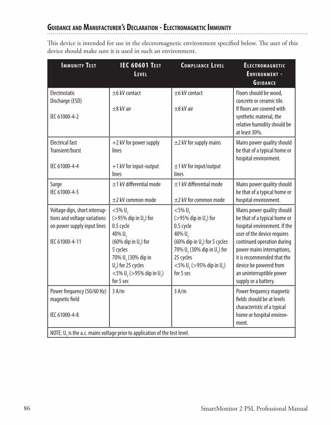
86 SmartMonitor 2 PSL Professional Manual
guIdanCe and ManufaCTurer’s deClaraTIon - eleCTroMagneTIC IMMunITy
Thisdeviceisintendedforuseintheelectromagneticenvironmentspecifiedbelow.Theuserofthisdeviceshouldmakesureitisusedinsuchanenvironment.
I M M u n I T y Te s T IeC 60601 Te s T l e v e l
C o M p l I a n C e l e v e l e l e C T r o M a g n e T I C e n v I r o n M e n T -
g u I d a n C e
Electrostatic Discharge (ESD)
IEC 61000-4-2
±6 kV contact
±8 kV air
±6 kV contact
±8 kV air
Floors should be wood, concrete or ceramic tile. If floors are covered with synthetic material, the relative humidity should be at least 30%.
Electrical fast Transient/burst
IEC 61000-4-4
+2 kV for power supply lines
+1 kV for input-output lines
±2 kV for supply mains
±1 kV for input/output lines
Mains power quality should be that of a typical home or hospital environment.
SurgeIEC 61000-4-5
±1 kV differential mode
±2 kV common mode
±1 kV differential mode
±2 kV for common mode
Mains power quality should be that of a typical home or hospital environment.
Voltage dips, short interrup-tions and voltage variations on power supply input lines
IEC 61000-4-11
<5% UT
(>95% dip in UT) for 0.5 cycle 40% UT
(60% dip in UT) for 5 cycles70% UT (30% dip in UT) for 25 cycles <5% UT (>95% dip in UT) for 5 sec
<5% UT
(>95% dip in UT) for 0.5 cycle 40% UT
(60% dip in UT) for 5 cycles70% UT (30% dip in UT) for 25 cycles<5% UT (>95% dip in UT) for 5 sec
Mains power quality should be that of a typical home or hospital environment. If the user of the device requires continued operation during power mains interruptions, it is recommended that the device be powered from an uninterruptible power supply or a battery.
Power frequency (50/60 Hz) magnetic field
IEC 61000-4-8
3 A/m 3 A/m Power frequency magnetic fields should be at levels characteristic of a typical home or hospital environ-ment.
NOTE: UT is the a.c. mains voltage prior to application of the test level.
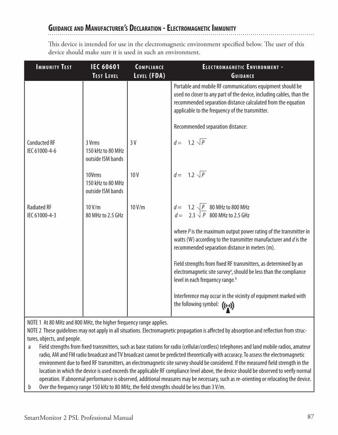
87SmartMonitor 2 PSL Professional Manual
guIdanCe and ManufaCTurer’s deClaraTIon - eleCTroMagneTIC IMMunITy
Thisdeviceisintendedforuseintheelectromagneticenvironmentspecifiedbelow.Theuserofthisdeviceshouldmakesureitisusedinsuchanenvironment.
I M M u n I T y Te s T IeC 60601 Te s T l e v e l
C o M p l I a n C e l e v e l (fda)
e l e C T r o M a g n e T I C e n v I r o n M e n T -g u I d a n C e
Conducted RFIEC 61000-4-6
Radiated RFIEC 61000-4-3
3 Vrms150 kHz to 80 MHz outside ISM bands
10Vrms150 kHz to 80 MHz outside ISM bands
10 V/m80 MHz to 2.5 GHz
3 V
10 V
10 V/m
Portable and mobile RF communications equipment should be used no closer to any part of the device, including cables, than the recommended separation distance calculated from the equation applicable to the frequency of the transmitter.
Recommended separation distance:
d = 1.2 P
d = 1.2 P
d = 1.2 P 80 MHz to 800 MHz d = 2.3 P 800 MHz to 2.5 GHz
where P is the maximum output power rating of the transmitter in watts (W) according to the transmitter manufacturer and d is the recommended separation distance in meters (m).
Field strengths from fixed RF transmitters, as determined by an electromagnetic site surveya, should be less than the compliance level in each frequency range.b
Interference may occur in the vicinity of equipment marked with the following symbol:
NOTE 1 At 80 MHz and 800 MHz, the higher frequency range applies.NOTE 2 These guidelines may not apply in all situations. Electromagnetic propagation is affected by absorption and reflection from struc-tures, objects, and people. a Field strengths from fixed transmitters, such as base stations for radio (cellular/cordless) telephones and land mobile radios, amateur
radio, AM and FM radio broadcast and TV broadcast cannot be predicted theoretically with accuracy. To assess the electromagnetic environment due to fixed RF transmitters, an electromagnetic site survey should be considered. If the measured field strength in the location in which the device is used exceeds the applicable RF compliance level above, the device should be observed to verify normal operation. If abnormal performance is observed, additional measures may be necessary, such as re-orienting or relocating the device.
b Over the frequency range 150 kHz to 80 MHz, the field strengths should be less than 3 V/m.

88 SmartMonitor 2 PSL Professional Manual
reCoMMended separaTIon dIsTanCes beTWeen porTable and MobIle rf CoMMunICaTIons equIpMenT and ThIs devICe
ThedeviceisintendedforuseinanelectromagneticenvironmentinwhichradiatedRFdisturbancesarecontrolled.ThecustomerortheuserofthisdevicecanhelppreventelectromagneticinterferencebymaintainingaminimumdistancebetweenportableandmobileRFcommunicationsequipment(transmitters)andthisdeviceasrecommendedbelow,accordingtothemaximumoutputpowerofthecommunicationsequipment.
r a T e d M a x I M u M po W e r o u T p u T o f Tr a n s M I T -
T e r
W
s e p a r a T I o n d I s T a n C e a C C o r d I n g T o f r e q u e n C y o f Tr a n s M I T T e r M
150 k h z T o 80 Mh z
d = 1.2 p80 Mh z T o 800 Mh z
d = 1.2 p800 Mh z T o 2.5 gh z
d = 2.3 p0.01 0.12 0.12 0.23
0.1 0.38 0.38 0.73
1 1.2 1.2 2.3
10 3.8 3.8 7.3
100 12 12 23
For transmitters rated at a maximum output power not listed above, the recommended separation distance d in meters (m) can be estimated using the equation applicable to the frequency of the transmitter, where P is the maximum output power rating of the transmitter in watts (W) according to the transmitter manufacturer.Note 1: At 80 MHz and 800 MHz, the separation distance for the higher frequency range applies.Note 2: These guidelines may not apply in all situations. Electromagnetic propagation is affected by absorption and reflection from structures, objects, and people.

89SmartMonitor 2 PSL Professional Manual
glossary
Apnea–Thecessationofbreathing(respirations).
Centralapnea–Norespiratoryeffort.
Obstructiveapnea–Cessationofairflowintooroutofthemouthornosealthougheffortstobreathcontinue.
Bradycardia–Slowingoftheheartratebelowtheagespecifiedrateforfivesecondsorgreater.
CardiopulmonaryResuscitation(CPR)–Aprocedureusedaftercardiacarrestinwhichcardiacmas-sage,mouth-to-mouthresuscitation,anddrugsareusedtorestorebreathing.
Electrode–Aconductorusedtoestablishelectricalcontactbetweenthemonitorandthepatient’sskin.
FunctionalSelf-Test–Auser-performedtesttoverifythemonitor,ECGpatientcable,andleadwiresareworkingproperly.
Heartrate–Thenumberofheartbeatsperminute.
Impedance–Amethodusedbythemonitortodetectrespiration.
LAConnection–TheopeningontheECGpatientcablemarked“LA”istheconnectorfortheblackleadwire.
Modem–Adevicethatallowsthehomecareproviderorhospitaltoworkwithamonitorthroughtelephonelines.
Oximeter–Aphotoelectricdevicethatmeasurestheamountofoxygenandotherfluidsintheblood.
%(Percent)SpO2–Ameasurementofhowmuchoxygeniscontainedinblood.Usuallymeasuredviaafinger,toeorearsensor.NotethattheSpO2measurementindicatesthefunctionalsaturation.
RAConnection–TheopeningontheECGpatientcablemarked“RA”istheconnectorforthewhiteleadwire.
Respiration–Theactofinhalingandexhalingair(breathing).
RLconnection–Useofthethird(green–RL)electrodeandleadwireisnormallynotrequiredbutmayhelpreduceexcessivefalselowheartratealarms.
StrainReliefArea–Locatedattheconnectingtipoftheleadwiresorcables,thisareahasaddedinsulationsurroundingthewirestopreventbreakagewhenhandled.Thisareaistobegraspedwhenremovingleadwires.

90SmartMonitor 2 PSL Professional Manual

1104083
HM 10/16/12
Manufactured for
Children’s Medical Ventures, LLC191 Wyngate DriveMonroeville, PA 15146 USA