SMART Energy Storage Guideline Stakeholder Meeting ESS... · 20/04/2018 · Creating A Clean,...
34
Creating A Clean, Affordable, and Resilient Energy Future For the Commonwealth SMART Energy Storage Working Group Meeting Boston, MA April 13, 2018
-
Upload
truongngoc -
Category
Documents
-
view
219 -
download
1
Transcript of SMART Energy Storage Guideline Stakeholder Meeting ESS... · 20/04/2018 · Creating A Clean,...

Creating A Clean, Affordable, and Resilient Energy Future For the Commonwealth
SMART Energy Storage Working Group Meeting
Boston, MA April 13, 2018

Creating A Clean, Affordable, and Resilient Energy Future For the Commonwealth
Agenda
1. Introduction (5 min)
2. Presentations (45min)
3. DOER Questions (30 min)
4. Public Comments (30 min)
2

Creating A Clean, Affordable, and Resilient Energy Future For the Commonwealth
Purpose of Today’s Meeting
DOER will guide a conversation on clarifying the details of the SMART Energy Storage Adder Guideline. DOER’s primary goal is to clarify the following the components of the adder in the Guideline:
1. How should DOER define “co-located”?
2. How should DOER enforce its requirement for Energy Storage Systems to discharge 52 complete cycle equivalents?
3. What format should DOER use to collect 15-minute interval data from Energy Systems as required under SMART?
DOER also plans to discuss how energy storage systems under SMART will interact with ISO-NE markets in order to ensure that benefits to ratepayers are maximized to the greatest extent possible.
3

SMART Storage Stakeholder Meeting Ron Nelson
April 13, 2018

Lon Huber Vice President
om
M: 415-275-1315
Ron Nelson Senior Consultant
om
M: 360-201-2827
Ed Burgess Director
eburgess@stratege
n.com
M: 941-266-0017
Strategen SMART team

▪ The operation requirement for energy storage systems participating in SMART is that it must have 52 complete cycle equivalents annually
▪ While ISO NE participation helps to align energy storage cycles with that of ratepayer benefits, no price signal is currently provided to avoid Regional Network Service (RNS) charges
Operational requirement
6
Timing of cycles is critically important for ratepayer benefits
Source: Energy Alabama

▪ Regional Network Load (RNL) costs as percent of total wholesale load costs
Regional network service charges
7
RNL costs for Northeastern Massachusetts have reached over $10,000/MW-Month
Source: ISO NE – Monthly Regional Network Load Cost Report December 2017
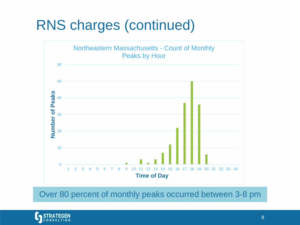
RNS charges (continued)
8
Over 80 percent of monthly peaks occurred between 3-8 pm
0
10
20
30
40
50
60
1 2 3 4 5 6 7 8 9 10 11 12 13 14 15 16 17 18 19 20 21 22 23 24
Nu
mb
er
of
Pe
ak
s
Time of Day
Northeastern Massachusetts - Count of Monthly Peaks by Hour

▪ Objective: lower Regional Network Service (RNS) charges
▪ Approach: provide the EDCs with 2 call options per month for FTM storage
▪ 24 hour notice
▪ Limited duration
▪ Only applies to front of the meter energy storage systems
▪ Open to residential pilot with aggregator
▪ C&I should have data collection
▪ Participants can opt-out but face a reduced incentive (Lon’s testimony has this value as 1 cent/kWh)
▪ Performance: the EDCs performance related to avoiding RNS charges would be monitored through an annual regulatory filing
▪ Potential for shared savings
Strategen’s proposal
9
Targeting energy storage discharge during periods of high demand can provide benefits for ratepayers

▪ Participation within ISO NE markets would not be impacted outside of the 2 call options per month
▪ Details still need to be finalized
▪ Duration of call option
▪ State of charge at the end of a called event
▪ Penalties for non-performance during events
Strategen’s proposal (continued)
10
Details of the proposal are not finalized—feedback is welcome

Thank You Ron Nelson Senior Consultant Strategen Consulting Email: [email protected] Web: www.strategen.com
11

Place your chosen
image here. The four
corners must just
cover the arrow tips.
For covers, the three
pictures should be the
same size and in a
straight line.
DOER Workshop on SMART Energy Storage
Adder Guideline
Department of Energy Resources
April 13, 2018

Definition of Co-located Storage
13
All of the definitions put forward for co-location – in the draft guideline, the SMART tariff proceeding and the SEIA, et al., comments need slight improvement to reflect the preferred interconnection infrastructure for all systems including large stand- alone solar + storage developments
The SEIA definition, with additional edits underlined, could be supported by National Grid:
“To be deemed co-located, the Solar Tariff Generation Unit and the Energy Storage System must be located on the same or adjacent parcels, and must be interconnected to the same common collector located on the same parcel(s) on which the STGU and ESS facilities are located (i.e. an electric service on such parcel(s) connected to an independent circuit at nominal AC voltage or distribution element that serves no other utility customers and no load other than that associated with the parcels on which the Solar Tariff Generation Unit(s) and Energy Storage Unit are located).”

Validation of ESS Cycling,
Operation Data and Efficiency
14
The EDCs have procured the services of the Solar Program
Administrator from CleaResult which include validating the
eligibility of STGUs to receive their adders under the guidelines
The SPA plans to set reporting requirements for all ESS to provide
sufficient evidence of 52 cycle discharges per year, the required
operational data collection and the evidence of efficiency
The EDCs understand DOER intends to provide more guidance on
the format of the data, timing of submission, and the time period
and method over which to assess round trip efficiency (first year,
life average, current year, etc.)

ISO-NE Participation and
Connection/Metering - BTM
15
The EDCs will install and own separate meters on both the solar
PV and ESS components of an STGU if they are, combined, equal
to or greater than 60 kW
The EDCs do not seek to separately meter ESS that are, combined
with on-site solar, less than 60kW at this time
For all Behind the Meter ESS facilities, National Grid would have
option to bid them as Passive On-Peak Demand Resources or
Settlement Only Resources
Energy from an POPDR ESS would remain with the owner, but
the owner could not participate in the ISO-NE energy market

ISO-NE Participation and
Connection/Metering - FTM
16
The EDCs anticipate owning capacity rights of and having the option to
participate in capacity markets with ESS facilities that are Front of the
Meter (FTM), requiring meters on each resource
The EDCs would encourage FTM ESS system owners to participate in the
ISO-NE market as Active Generators whereby the units would be
dispatched in the Day Ahead Energy Market, and could support
performance as capacity resources in the FCM
If such ESS were not active generators, the EDCs would seek for the
owners to enroll such facilities as Settlement Only Generators, and would
intend to register the facilities as Settlement Only Resources in the FCM if
they meet the minimum size requirements in the FCM
Facilities that do not meet the minimum size requirements in the FCM
would receive Performance Incentive payments if generating during
Capacity Scarcity Conditions

www.borregosolar.com © Borrego Solar Systems, Inc. Private & Confidential
MA SMART ES Guideline
MA SMART Energy Storage Guideline Technical Session

www.borregosolar.com © Borrego Solar Systems, Inc. Private & Confidential
MA SMART ES Guideline
Topic #1 - Co-location
Guideline specifies that the PV and ESS should share a “common point of coupling”
“Point of Common Coupling” as defined in the interconnection tariff
o “Point of Common Coupling (PCC)” shall mean the point where the Interconnecting Customer’s local electric power system connects to the Company EPS, such as the electric power revenue meter or Company’s service transformer. The PCC shall be specified in the Interconnection Service Agreement.
These two terms are easily conflated
We are interested in each of the utilities’ interpretation of “common point of coupling,” and whether that effectively means, “behind the same utility meter”
Multiple use cases envisioned by State of Charge would potentially be constrained by a single-point of common coupling approach
We encourage DOER to include sample diagrams in the guideline, and include a waiver process for configurations that aren’t evident today

www.borregosolar.com © Borrego Solar Systems, Inc. Private & Confidential
MA SMART ES Guideline
Topic #1 - Co-location
Single-meter configuration use cases
Behind the meter, C&I demand charge management (DCM) or resiliency use cases
Behind the meter, residential DCM or resiliency/backup power
Front of meter, renewables integration, interconnection impact mitigation, both AC- and DC-coupled
M
ESS
STGU
Point of Common
Coupling (PCC)
Utility Jurisdictional
Distribution Feeder

www.borregosolar.com © Borrego Solar Systems, Inc. Private & Confidential
MA SMART ES Guideline
Topic #1 - Co-location
Dual-meter configuration use cases
Behind the meter, C&I demand charge management (DCM) ESS + FTM PV
Behind the meter, campus-style arrangement with ESS & PV behind separate meters
Front of meter, wholesale market participation
o STGU and ESS can be brought to the wholesale market as separate assets
“common point of coupling” could refer to a common distribution element that serves no load other than the customer and/or PV+ES station service
M
M ESS
STGU
Common Point of
Coupling
Utility Jurisdictional
Distribution Feeder
Customer
Load
Customer
Load
www.borregosolar.com © Borrego Solar Systems, Inc. Private & Confidential
MA SMART ES Guideline
Topic #1 - Co-location
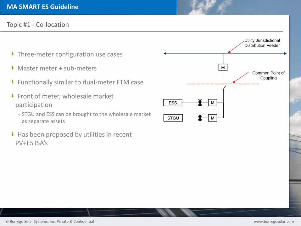
Three-meter configuration use cases
Master meter + sub-meters
Functionally similar to dual-meter FTM case
Front of meter, wholesale market participation
o STGU and ESS can be brought to the wholesale market as separate assets
Has been proposed by utilities in recent PV+ES ISA’s
M
M ESS
STGU
Common Point of
Coupling
Utility Jurisdictional
Distribution Feeder
M

www.borregosolar.com © Borrego Solar Systems, Inc. Private & Confidential
MA SMART ES Guideline
Topic #2 – Discharge and Cycling Requirements
Degradation and Depth of Discharge (DoD) will vary between technologies, chemistries, and use cases
Cycle Equivalent = Rated energy capacity of the ESS at 100% depth of discharge (same as California SGIP program)
o Example: The cycle equivalent of a 1MW/2MWh battery is 2MWh, regardless of technology
Annual minimum discharge for ESS adder compliance should be determined in Year 1
o (Annual minimum discharge) = 52 * (Rated Energy Capacity)
o Example: 1MW/2MWh ESS, annual min discharge = 52 * 2MWh = 104MWh
DoD Restrictions: Chemistries with DoD restrictions will need to cycle > 52 times
o Example: 1MW/2MWh ESS with a 95% DoD restriction achieves 1.9MWh per cycle, and will need to cycle 54.75x to meet the 104MWh annual minimum requirement
Degradation: The ESS should meet its annual minimum requirement for the full term of the adder
o Example: 1MW/2MWh ESS with 1.5% annual degradation (see table)
Year Energy Capacity
(kWh)
Required
Cycles/y
r
1 1900
54.74
2 1872
55.57
3 1843
56.42
4 1816
57.28
5 1789
58.15
6 1762
59.03
7 1735
59.93
8 1709
60.85
9 1684
61.77
10 1658
62.71
11 1633
63.67
12 1609
64.64
13 1585
65.62
14 1561
66.62
15 1538
67.64

www.borregosolar.com © Borrego Solar Systems, Inc. Private & Confidential
MA SMART ES Guideline
Topic #2 – Discharge and Cycling Requirements – Additional Considerations
Reporting requirements for discharge and cycling should not favor some PV+ES architectures over others
o Example: AC-Coupled system could comply with a utility-grade metering requirement, whereas the availability of ‘utility-grade’ DC meters may be limited
o For DC-coupled systems, DOER should accept discharge and cycle reporting from the power conversion system or inverter’s native metering
Dispatch requirements introduced through the SMART docket or guidline should not interfere with the ESS’ core economic use cases or prejudice certain ESS configurations
o Example: An ESS performing ancillary services, renewable smoothing, or DCM may receive a utility dispatch signal that conflicts with those operations
o DOER should not impose additional dispatch requirements for behind-the-meter systems due to complications with onsite load interactions.
o A 1MW/2MWh ESS cannot respond to a four-hour utility dispatch signal without reducing its power capacity to 500kW for the duration of that discharge cycle;
• Depth of Discharge restrictions and degradation over time are also important to keep in mind if discharge signals are going to be required
o Removal from SMART for alleged failure to respond to dispatch signals should be subject to fair hearing provisions and reasonable force majeure exceptions.
www.borregosolar.com © Borrego Solar Systems, Inc. Private & Confidential
MA SMART ES Guideline
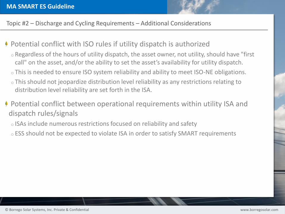
Topic #2 – Discharge and Cycling Requirements – Additional Considerations
Potential conflict with ISO rules if utility dispatch is authorized
o Regardless of the hours of utility dispatch, the asset owner, not utility, should have "first call" on the asset, and/or the ability to set the asset’s availability for utility dispatch.
o This is needed to ensure ISO system reliability and ability to meet ISO-NE obligations.
o This should not jeopardize distribution level reliability as any restrictions relating to distribution level reliability are set forth in the ISA.
Potential conflict between operational requirements within utility ISA and dispatch rules/signals
o ISAs include numerous restrictions focused on reliability and safety
o ESS should not be expected to violate ISA in order to satisfy SMART requirements

www.borregosolar.com © Borrego Solar Systems, Inc. Private & Confidential
MA SMART ES Guideline
Topic #3 – ISO-NE & Wholesale Market Participation
Participation models for PV & ES under current ISO-NE asset classifications
o FTM: Dual-meter (or three-meter) configuration, registered as a Generator. Access to Capacity, Regulation & Reserves
o BTM: Three meter configuration, registered as a Passive Demand Response or Demand Response Capacity Resource
In FTM Generator model, ISO requires “separate interconnection rights” for PV & ES
o Does this mean separate ISA’s? Separate Points of Interconnection?
o ISO-NE has indicated that for all Energy Storage applications seeking to participate as a Generator, the Interconnection Request should be submitted through ISO-NE’s Interconnection Request Tracking Tool (IRTT), and follow the Schedule 23 process

© EnerNOC, Inc. All rights reserved.
www.enernoc.com
April 13, 2018
Maximizing Ratepayer Benefits
from SMART

27 © EnerNOC, Inc. All rights reserved.
www.enernoc.com
Click to edit Master title style
Reduce peak demand, system losses, the need for investment in new
infrastructure, and distribution congestion
Increase grid reliability; improve public health and safety; and diversify the
Commonwealth's energy supply
SMART Objectives

28 © EnerNOC, Inc. All rights reserved.
www.enernoc.com
Click to edit Master title style
* As noted in the MA State of Charge report, there is uncertainty over whether storage can reduce transmission cost allocation for
utilities
Use the 52 Cycles Strategically to Align
with these Objectives and Reduce
Ratepayer Costs Require storage owners to cycle through one or more of the following
mechanisms; each mechanism delivers benefits to all ratepayers; give
owners flexibility to choose, as long as they can demonstrate compliance;
dispatch triggers must be transparent and provide sufficient notice
Mechanism/Purpose Dispatch Trigger Ratepayer Benefit
ISO-NE wholesale
market participation
ISO-NE dispatch control Reduced wholesale
prices; reliability
Peak shaving (summer
or winter); transmission
& distribution cost
reduction
Dispatch at 96% of
forecasted utility peak
(trigger for current NGrid
peak shaving)
Lower T&D costs and
mitigate LMP spikes;
system efficiency - (top
1% causes 8% of costs)
Reduce wholesale cost
allocation for MA
Near single hour ISO-NE
system peak or local
non-coincident monthly
peaks*
Lower capacity and
transmission costs for
MA ratepayers
Confidential | © 2018 SunPower Corporation
SMART PV + Storage
Co-Location Scenarios
Becky Gallagher | April 13 2018

3
0 Confidential | © 2018 SunPower Corporation |
PV + Storage – Co-location & Incentive Issues
1) Determination of “Colocation”
2) Calculation of storage adder rate
3) PV kWh production applied to storage adder
Recommendation: “Co-location” definition
incorporate concept of “behind meters associated
with same utility account” for behind the meter
projects and reflect that in the SQA process.

3
1 Confidential | © 2018 SunPower Corporation |
Example 1: One customer meter, single utility service drop, single STGU
M
ESS
(100
kW /
200
kWh)
STGU
BM
(500
kW)
Utility Jurisdictional
Distribution Circuit
Custom
er Load
Custom
er Load
M Utility retail
meter
M Smart program
meter
MA
M
Single
Parcel
Other
customer
Co-Location: Utility service
drop meets definition of (a)
PCC and (b) “Common
Collector” language in
comments. All PV and
Battery behind that service
drop are “Co-Located”
Storage Adder Rate: based
on kW of STGU A (500 kW)
and 100 kW / 200 kWh of
storage
Storage Adder Payment:
based on total production
metered at MA
Utility
Service
Drop
3
2 Confidential | © 2018 SunPower Corporation |
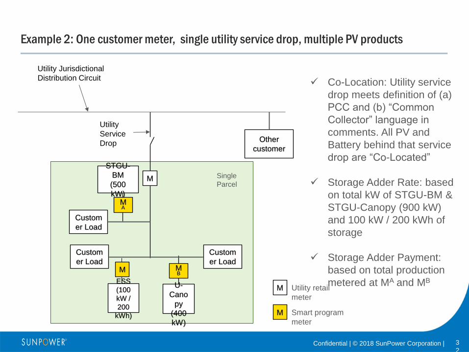
Example 2: One customer meter, single utility service drop, multiple PV products
M
ESS
(100
kW /
200
kWh)
STGU-
BM
(500
kW)
Utility Jurisdictional
Distribution Circuit
Custom
er Load
Custom
er Load
Custom
er Load
M Utility retail
meter
M Smart program
meter
MA
M
Single
Parcel
Other
customer
STG
U-
Cano
py
(400
kW)
Co-Location: Utility service
drop meets definition of (a)
PCC and (b) “Common
Collector” language in
comments. All PV and
Battery behind that service
drop are “Co-Located”
Storage Adder Rate: based
on total kW of STGU-BM &
STGU-Canopy (900 kW)
and 100 kW / 200 kWh of
storage
Storage Adder Payment:
based on total production
metered at MA and MB
Utility
Service
Drop
MB

3
3 Confidential | © 2018 SunPower Corporation |
Example 3: Multiple customer meters, single account, single utility service, multiple PV
products
ESS
(100
kW /
200
kWh)
STGU
-BM
(500
kW)
Utility Jurisdictional
Distribution Circuit
Custom
er Load
Custom
er Load
Custom
er Load
Custom
er Load
M Utility retail
meter
M Smart program
meter
MA
M
Single
Parcel
Other
customer
STGU-
Canopy
(400
kW)
Co-Location: Utility service
drop meets definition of (a)
PCC and (b) “Common
Collector” language in
comments. All PV and
Battery behind that service
drop are “Co-Located”
Storage Adder Rate: based
on total kW of STGU-BM &
STGU-Canopy (900 kW)
and 100 kW / 200 kWh of
storage
Storage Adder Payment:
based on total production
metered at MA and MB
Utility
Service
Drop
MB
M
M M
M
Meters
aggregate
d and
billed as
one
account
3
4 Confidential | © 2018 SunPower Corporation |
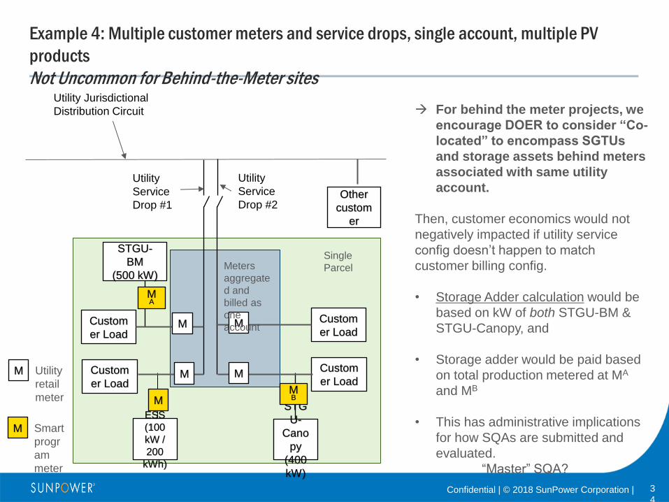
Example 4: Multiple customer meters and service drops, single account, multiple PV
products
Not Uncommon for Behind-the-Meter sites
STGU-
BM
(500 kW)
Utility Jurisdictional
Distribution Circuit
Custom
er Load
Custom
er Load
Custom
er Load
Custom
er Load M Utility
retail
meter
M Smart
progr
am
meter
MA
M
Single
Parcel
Other
custom
er
STG
U-
Cano
py
(400
kW)
For behind the meter projects, we
encourage DOER to consider “Co-
located” to encompass SGTUs
and storage assets behind meters
associated with same utility
account.
Then, customer economics would not
negatively impacted if utility service
config doesn’t happen to match
customer billing config.
• Storage Adder calculation would be
based on kW of both STGU-BM &
STGU-Canopy, and
• Storage adder would be paid based
on total production metered at MA
and MB
• This has administrative implications
for how SQAs are submitted and
evaluated.
“Master” SQA?
Utility
Service
Drop #1
MB
M
M
Utility
Service
Drop #2
M
M
Meters
aggregate
d and
billed as
one
account
ESS
(100
kW /
200
kWh)