Small or medium-Scale focused research project (STREP) · PDF fileEDD – Extended Dry...
43
Small or medium-Scale focused research project (STREP) STT Call 1 FP7-STT-RDT-1 MINOAS Deliverable D2 – Tentative draft Rules for acceptance of a hull robot Inspection Author(s): Lloyds, RINA Contributor(s) Status -Version: 1.6 Delivery Month: M36 Submission Date: April 2012 Workpackage, Task: WP1 Distribution – Security*: PU Deliverable Type and Number**: R D2 Code: * Security: PU – Public, PP - Restricted to other programme participants (including the Commission Services) RE - Restricted to a group specified by the consortium (including the Commission Services) CO - Confidential, only for members of the consortium (including the Commission Services) ** Type: R - Report, P - Prototype, D - Demonstrator, O – Other Abstract: The document was intended to presents a tentative draft rule for the acceptance of remote inspection techniques with the aid of robots during surveys of ships. For reasons that we will discuss herein we may only present the procedural guidelines for the acceptance of robotic inspection techniques for hull inspection. We will present the experience of the Oil & Gas industry from using remote inspection techniques in marine environment and draw upon their findings. Finally, we will describe the procedures of RINA and Lloyd’s Register for issuing new Rules or for amending existing ones. Keywords: Draft rules, robot, inspection Copyright by the MINOAS Consortium, 2012
Transcript of Small or medium-Scale focused research project (STREP) · PDF fileEDD – Extended Dry...

Small or medium-Scale focused research project (STREP)
STT Call 1
FP7-STT-RDT-1
MINOAS
Deliverable D2 – Tentative draft Rules for acceptance of a hull robot Inspection
Author(s): Lloyds, RINA
Contributor(s)
Status -Version: 1.6
Delivery Month: M36
Submission Date: April 2012
Workpackage, Task: WP1
Distribution – Security*: PU
Deliverable Type and Number**: R D2
Code: * Security: PU – Public, PP - Restricted to other programme participants (including the Commission Services)
RE - Restricted to a group specified by the consortium (including the Commission Services)
CO - Confidential, only for members of the consortium (including the Commission Services)
** Type: R - Report, P - Prototype, D - Demonstrator, O – Other
Abstract:
The document was intended to presents a tentative draft rule for the acceptance of remote inspection techniques with
the aid of robots during surveys of ships. For reasons that we will discuss herein we may only present the procedural
guidelines for the acceptance of robotic inspection techniques for hull inspection. We will present the experience of the
Oil & Gas industry from using remote inspection techniques in marine environment and draw upon their findings.
Finally, we will describe the procedures of RINA and Lloyd’s Register for issuing new Rules or for amending existing
ones.
Keywords:
Draft rules, robot, inspection
Copyright by the MINOAS Consortium, 2012

i
Document Revision History
Date Version Author/Editor/Contributor Version Description
19/07/2010 0.1 William Bateman First Draft
24/08/2011 0.2 Kim Tanneberger Second Draft to incorporate
changes to Technical Annex.
10/10/2011 0.3 Kim Tanneberger Third Draft to incorporate work
from LR Energy (Raymond
Caldwell).
15/12/2011 1.0 Aristeidis Diplaros Reorganizing report’s structure,
addition of new material,
improved readability
15/12/2011 1.1 Kim Tanneberger Minor amendments and insertion
of ROV inspection procedure
10/01/2012 1.2 J. Henton and R. Caldwell Review and Comments
27/01/2012 1.3 Kim Tanneberger Implementation of Comments
07/02/2012 1.4 J. Henton and Kim
Tanneberger
Further Implementation of
Comments
27/02/2012 1.5 K. Tanneberger Section 4.3
23/03/2012 1.6+Final K. Tanneberger RINA comments and Format

ii
Table of Contents
1 Introduction ............................................................................................................................................................... 1 2 Definitions ................................................................................................................................................................ 2 3 Regulatory Bodies..................................................................................................................................................... 3
3.1 IMO and Flag States ........................................................................................................................................ 3 3.2 Classification Societies.................................................................................................................................... 3
3.2.1 Class Rules .................................................................................................................................................. 4 3.3 International Association of Classification Societies - IACS .......................................................................... 4
3.3.1 IACS issued UR .......................................................................................................................................... 4 3.3.2 IACS issued PR........................................................................................................................................... 6 3.3.3 IACS issued Recommendations .................................................................................................................. 7
3.4 Why this project cannot provide a tentative draft of Classification Societies Rules ....................................... 7 Offshore Oil & Gas Industry Experience .......................................................................................................................... 9
3.5 Floating Offshore Installations ........................................................................................................................ 9 3.6 Development of the Offshore Class .............................................................................................................. 10 3.7 Integrity Management ................................................................................................................................... 11 3.8 Inspection Schedules ..................................................................................................................................... 11 3.9 FOIs Inspection ............................................................................................................................................. 11 3.10 Present Class Status in Oil & Gas sector ....................................................................................................... 12 3.11 ROVs in Oil & Gas Sector ............................................................................................................................ 13
3.11.1 Oil & Gas Typical ROV Characteristics ............................................................................................... 13 3.11.2 Oil & Gas Typical ROV Usage ............................................................................................................ 14 3.11.3 Oil & Gas Industry Feedback ............................................................................................................... 14
4 Proposals ................................................................................................................................................................. 16 4.1 Procedural guidelines for the acceptance of robotic inspection of ships’ hull ............................................... 16 4.2 Draft Inspection Procedure ............................................................................................................................ 16
4.2.1 General ...................................................................................................................................................... 16 4.2.2 Abbreviations ............................................................................................................................................ 17 4.2.3 Applicability ............................................................................................................................................. 17 4.2.4 Objective ................................................................................................................................................... 18 4.2.5 Definitions ................................................................................................................................................ 18 4.2.6 Responsibilities ......................................................................................................................................... 20 4.2.7 Inspection Equipment ............................................................................................................................... 20 4.2.8 Safety Requirements ................................................................................................................................. 22 4.2.9 Site Requirements ..................................................................................................................................... 24 4.2.10 Inspection ............................................................................................................................................. 24 4.2.11 Reporting .............................................................................................................................................. 24 4.2.12 Assessment Criteria .............................................................................................................................. 24 4.2.13 Appendix - Approval of ROV Inspection Services .............................................................................. 28
4.3 Roadblocks .................................................................................................................................................... 30 5 Description of RINA / LR management process for technical Rules ..................................................................... 31
5.1 Technical rules issued by RINA .................................................................................................................... 31 5.2 Technical rules issued by LR ........................................................................................................................ 31 5.3 Proposals for additions or amendments to rules ............................................................................................ 32 5.4 Rule updating program .................................................................................................................................. 33 5.5 Draw up of the proposal ................................................................................................................................ 33 5.6 Review and approval ..................................................................................................................................... 34 5.7 Publication of Rules ...................................................................................................................................... 34
APPENDIX A - Comparison of the applicable regulations in the UK Offshore Industry .............................................. 37

1
1 Introduction
This deliverable is entitled “Tentative draft Rules for acceptance of a hull robot Inspection”.
This document presents a draft for Classification Societies’ Procedures for the acceptance of a
hull Robot inspection techniques. For reasons, that will be made clear herein, we can only propose
procedural guidelines for the acceptance of ship’s hull robotic inspection techniques and describe
the procedures of RINA and Lloyd’s Register for issuing new Rules or for amending existing ones.
This document is organized as follows. In Section 3, we will provide a comprehensive
description of the regulatory bodies of the marine industry and discuss some key issues regarding
their operations. Namely, we will describe the purpose and function of the Classification Societies,
their Rules and their association organization IACS. We will also elaborate why we cannot provide
a tentative draft of Classification Societies Rules.
In Section 0, we will provide the experience of the Oil & Gas Industry dealing with similarly
challenging issues. Specifically, we will include a brief description of the Floating Offshore
Installations for Oil & Gas Exploration and Exploitation, a discussion of the unique characteristics
of the Oil & Gas industry and the constrains they impose on the classification procedures. Finally,
we will provide an extensive description of the experience of this industry with the use of remotely
inspection techniques.
Finally, in Section 4 we will conclude with the procedural guidelines for the acceptance of
robotic inspection of ships’ hull and the description of the procedures for the amendment of
existing Rules and/or issue of new Rules by RINA and Lloyd’s Register.

2
2 Definitions
IMO - International Maritime Organization
IACS – International Association of Classification Societies
SOLAS – International Convention for the Safety of Life at Sea
EDD – Extended Dry Docking survey
ESP – Enhanced Survey Programme
IWS – In-Water Survey
UR – Unified Requirement
ROVs - Remotely Operated Vehicles
OBSROV - Observer Class ROV
WROV - Working Class ROV
FPSO - Floating Production Storage and Offloading
UT – Ultrasonic Thickness Measurement
ACFM - Alternating Current Field Measurement
FOI - Floating Offshore Installation
MARPOL - International Convention for the Prevention of Pollution From Ships
EEx - equipment corresponds to a type of protection covered by specific European Standards (e.g.
EN 60079-1)
TM – Thickness Measurement
CP - Cathodic Protection

3
3 Regulatory Bodies
In this section we will provide a comprehensive description of the regulatory bodies of the marine
industry and discuss some key issues regarding their operations. Namely, we will describe the
purpose and function of the Classification Societies, their Rules and their association organization
IACS. We will describe the Unified Requirements, the Procedural Requirements and
Recommendations issued by IACS. Finally, we will elaborate why we cannot provide a tentative
draft of Classification Societies Rules and will discuss alternatives.
3.1 IMO and Flag States
The International Maritime Organization (IMO) is a specialised agency of the United Nations and
its primary purpose is to develop and maintain a comprehensive regulatory framework for
shipping. This includes safety, environmental concerns, legal matters, technical co-operation,
maritime security and the efficiency of shipping. IMO's specialized committees and sub-
committees are the focus for the technical work to update existing legislation or develop and adopt
new regulations, with meetings attended by maritime experts from Member Governments, together
with those from interested intergovernmental and non-governmental organizations. The result is a
comprehensive body of international conventions, supported by hundreds of recommendations,
which governs every facet of shipping. The International Convention for the Safety of Life at Sea
(SOLAS), the International Convention for the Prevention of Pollution from Ships (MARPOL) and
the International Convention on Load Lines are among the most important conventions adopted by
IMO. The enforcement of IMO’s Conventions is responsibility of Flag (and Port) States (i.e., UN
member States).
3.2 Classification Societies
Classification Societies’ purpose is to provide classification and statutory services regarding
maritime safety and pollution prevention and assistance to the maritime industry and regulatory
bodies, based on their accumulated maritime knowledge and experience. Their significance has
been formally recognised by the flag States, whose administrations can, and commonly do,
designate Classification Societies as Recognised Organisation1 to act on their behalf for statutory
certification purposes. Specifically, SOLAS and MARPOL explicitly allow the delegation of Flag
State’s certification responsibilities to Recognised Organisations. Additionally, the 1988 Protocol
to the International Convention on Load Lines actually recognizes that Classification Societies set
the standards of ships’ design, construction and maintenance in order for them to be considered of
“acceptable level of strength”2 for sea. Of course, Classification Societies are just one link in the
long chain of upholding maritime safety. Others with a responsibility for, or interest in promoting
maritime safety include seafarers, shipbuilders, Flag State administrations, Port State Control
authorities, underwriters, shipping financiers, charterers, and, of course, ship-owners.
Classification Societies are independent, self-regulating and externally audited bodies, with no
commercial interests related to ship design, ship building, ship ownership, ship operation, ship
management, ship maintenance or repairs, insurance, or chartering. Each Classification Society
1 In some cases they may be referred as “Recognised Security Organisations”.
2 “Load Lines, 1966/1988 - International Convention on Load Lines, 1966, as Amended by the Protocol of 1988-
Annex I - Regulations for Determining Load Lines - Chapter I - General - Regulation 1 - Strength and intact stability
of ships”.

4
lays down a number of standards, to which commercial ships are designed, built and maintained
for compliance with. These standards constitute each Society’s Classification (Class) Rules.
3.2.1 Class Rules
Classification Rules are essentially standards for the structural strength of the ship’s hull and its
appendages, and the suitability of the propulsion and steering systems, power generation and those
other features and auxiliary systems, which have been built into the ship to assist in its operation,
but are considered to significantly contribute to its safety. Classification Rules are not intended as
a design code and in fact cannot be used as such. In establishing these Rules, the Society may draw
upon the advice and review of members of the industry and academia who are considered to have
relevant knowledge or experience.
A vessel built in accordance with the applicable Rules of Classification Society may be assigned a
class designation by the Society on satisfactory completion of the relevant surveys. For ships in
service, the Society carries out surveys to verify that the ship remains in compliance with those
Rules. Should any defects that may affect class become apparent, or damages be sustained between
the relevant surveys, the owner is required to inform the Society concerned without delay.
3.3 International Association of Classification Societies - IACS
A number of the world’s Classification Societies constitute the International Association of
Classification Societies (IACS). It is estimated that the Members of IACS collectively class over
90 percent of all commercial tonnage involved in international trade worldwide. Thus the vast
majority of commercial ships have to follow the Rules of IACS Members.
3.3.1 IACS issued UR
One of the functions of IACS is to specify Unified Requirements (UR), which are the minimum
technical requirements to be adopted by the association member Societies. UR are relevant to
matters directly connected to or covered by specific Rule requirements and practices of
Classification Societies and the general philosophy on which the Rules and practices of
Classification Societies are established. UR are subject to ratification by the governing body of
each IACS Member and are to be incorporated in their Rules and practices. It needs to be noted
that UR set forth minimum requirements; each IACS Member remains free to set more strict
requirements.
The general requirements relating to ships’ survey and certification are contained into IACS UR
part Z. The requirements of the survey of ship’s hull are contained in UR Z7. Specific
requirements applicable to tankers, bulk carriers, chemical tankers, double hulled tankers, double
skin bulk carriers, general dry cargo ships and liquefied gas carriers are contained in UR Z10.1,
Z10.2, Z10.3, Z10.4, Z10.5, Z7.1 and Z7.2 respectively. In UR Z23 the requirements for hull
survey for new construction ships can be found.
The common theme in these requirements is that they all define the term close-up survey as ‘a
survey where the details of structural components are within the close visual inspection range of
the surveyor i.e. normally within reach of hand.’ The aforementioned UR also specify the hull’s
areas and the frequency that these close-up surveys must be conducted. For example the schemas
in Figure 1 are taken from UR Z10.4 which deals with the survey and certification of double hull

5
oil tankers. The areas enclosed by the dotted lines represent typical hull areas for close-up survey
during the Special Survey (typically, every five years). The locations marked with ‘v’ are
suggested for thickness measurements. In Figure 2 the minimum requirements for “thickness
measurements” at special survey of double hull oil tankers are outlined. Note that these schemas
hold for areas of no substantial corrosion. In case of substantial corrosion3 additional
measurements are required as clearly denoted in the same UR.
We included these example figures to provide an idea of the type of information contained in the
UR and give an indication of the level of technical detail therein.
Figure 1, Close-up Survey Requirements and Thickness Measurements locations for Double Hull Oil Tankers
Areas as shown in UR Z10.4
3 The UR defines Substantial Corrosion as ‘an extent of corrosion such that assessment of corrosion pattern indicate a
wastage in excess of 75% of allowable margins, but within acceptable limits. For vessels built under the IACS
Common Structural Rules, substantial corrosion is an extent of corrosion such that the assessment of the corrosion
pattern indicates a gauged (or measured) thickness between tnet + 0.5mm and tnet.’

6
Figure 2, Minimum Requirements for Thickness Measurements at Special Survey of Double Hull Oil Tankers
Another interesting Unified Requirement to us is UR Z17, which specifies the procedural
requirements for service suppliers. This UR makes clear reference to firms engaging in thickness
measurements and provides the framework for their qualification from the Classification Societies.
This also includes requirements on the competencies of the key firms’ personnel4.
3.3.2 IACS issued PR
IACS passes Resolutions on technical matters of procedure as IACS Procedural Requirements
(PR). Requirements under this category are to be followed by the all member Classification
Societies. The adopted PRs are to be incorporated in the practices and procedures of the Members
within pre-agreed periods.
The IACS PR No. 19 is of special interest for us. It specifies the procedural requirements for
thickness measurements, when they are carried out by a third party and not the Class’ surveyor.
Since, these measurements are required in the context of hull structural classification surveys this
particular PR specifies the framework within which these shall be performed.
The requirement actually states that:
“1. Thickness Measurements required in the context of hull structural classification surveys, if not carried out by the Society itself shall be witnessed by a surveyor. The attendance of the surveyor shall be recorded. 2. This requires the surveyor to be on board, while the gaugings are taken, to the extent necessary to control the process. … 2.2 Monitoring of the thickness measurement process onboard The surveyor is to decide final extent and location of thickness measurements after overall survey of representative spaces onboard.
4 See “UR Z17 - Annex 1 Special Requirements for Various Categories of Service Suppliers - 1. Firms engaged in
thickness measurements on ships” where it states that: “The responsible supervisor shall be qualified according to a
recognised national or international industrial NDT standard (e.g. EN 473 level II or ISO 9712 level II)”
7
… Thickness measurements of structures in areas where close-up surveys are required shall be carried out simultaneously with close-up surveys. 2.3 Review and verification Upon completion of the thickness measurements, the surveyor is to confirm that no further gaugings are needed, or specify additional gaugings. …”
What is important to note is that the aforementioned PR puts the surveyor in charge of the
measurement process.
3.3.3 IACS issued Recommendations
IACS also produces recommendations related to adopted resolutions that are not necessarily
matters of class but which IACS considers would be helpful to offer some advice to the marine
industry.
The IACS Recommendation No.42 is of special interest for us. This recommendation provides the
guidelines for the use of Remote Survey Techniques and actually states that:
“1.1 Remote Inspection Technique methods may be used to facilitate the required internal
examinations, including close-up surveys and gaugings required with close-up surveys. The
methods applied for Remote Inspection Techniques are to provide the survey results normally
obtained for the Surveyor.
1.2 Confirmatory close-up surveys are to be carried out by the Surveyor at selected locations
where close up surveys are required to verify the results of the Remote Inspection Technique
methods. Proposals for use of Remote Inspection Technique methods are to be submitted to the
Classification Society for approval in advance of the survey. The Classification Society will review
the proposal and approve the arrangements including minimum requirements for confirmatory
close-up surveys.”
What is important to note is that the aforementioned Recommendation allows the use of remote
inspection techniques provided that they are presented to and approved by the Classification
Societies and that close-up survey is still performed where necessary.
3.4 Why this project cannot provide a tentative draft of Classification Societies Rules
The document does not present a tentative draft of Rules for the acceptance of remote inspection
techniques with robotic aid during ships’ surveys, despite the title of the deliverable. There are two
reasons why we cannot provide that.
The first reason is that Rules do not contain ships’ survey procedures, which is what this
deliverable was intended to provide. Rules and Regulations are Classification Societies’ published
standards on the design/construction of ships in order to be classed and on their maintenance in
8
order to remain in class5. Even though Rules do specify the items to be periodically surveyed in
order for the ship to stay in Class, they do not specify the way to conduct the survey. This is
specified in survey procedures, which are, if they are not originated through IACS, internal,
confidential and unique for each Classification Society.
The process to arrive at an IACS procedure is one of expert opinion and technical research, the
work presented here can not deliver a full basis for this either, but form the starting point for an
expert debate.
Therefore, we can provide neither Rules relating to ‘inspection’ nor published ship’s inspection
procedure common for all Classification Societies.
However, in 4.2. we give a suggested methodology to utilise remote survey techniques.
5 From Lloyd’s Register Rules and Regulation - Chapter 2 Classification Regulations - §1.1.2. “Ships built in
accordance with Lloyd’s Register’s (hereinafter referred to as LR) Rules and Regulations, or in accordance with requirements equivalent thereto, will be assigned a class in the Register Book and will continue to be classed as long as they are found, upon examination at the prescribed surveys, to be maintained in accordance with the requirements of the Rules. Classification will be conditional upon compliance with LR’s requirements for both hull and machinery and with the Certification Requirements of 1.1.”
9
Offshore Oil & Gas Industry Experience
In this section, we will include a brief description of the Floating Offshore Installations for Oil &
Gas Exploration and Exploitation, a discussion of the unique characteristics of the Oil & Gas
industry and the constrains they impose on the classification procedures. We will also provide an
extensive description of the experience of this industry with the use of remotely inspection
techniques.
3.5 Floating Offshore Installations
The Offshore Oil & Gas industry has developed very differently from the more traditional marine
industry. Its legislative & regulatory framework is varied throughout the world and is more often
than not governed by the Host Country's Department of Energy (DoE) or equivalent. The UK
model, which has been adopted to varying degrees globally, is that of self regulation. Under the
UK's Safety Case Regulations (SCR), the asset owner is required to identify major accident
hazards (MAH) and from these, Safety Critical Elements (SCEs). They are then required to
produce a Performance Standard for each SCE outlining how they will assure the integrity and
reliability of the SCE. This statutory framework is significantly different from the one which the
marine industry operates under, where IMO Conventions and Classification Societies impose the
statutory/regulatory requirements upon the ocean going trading vessel.
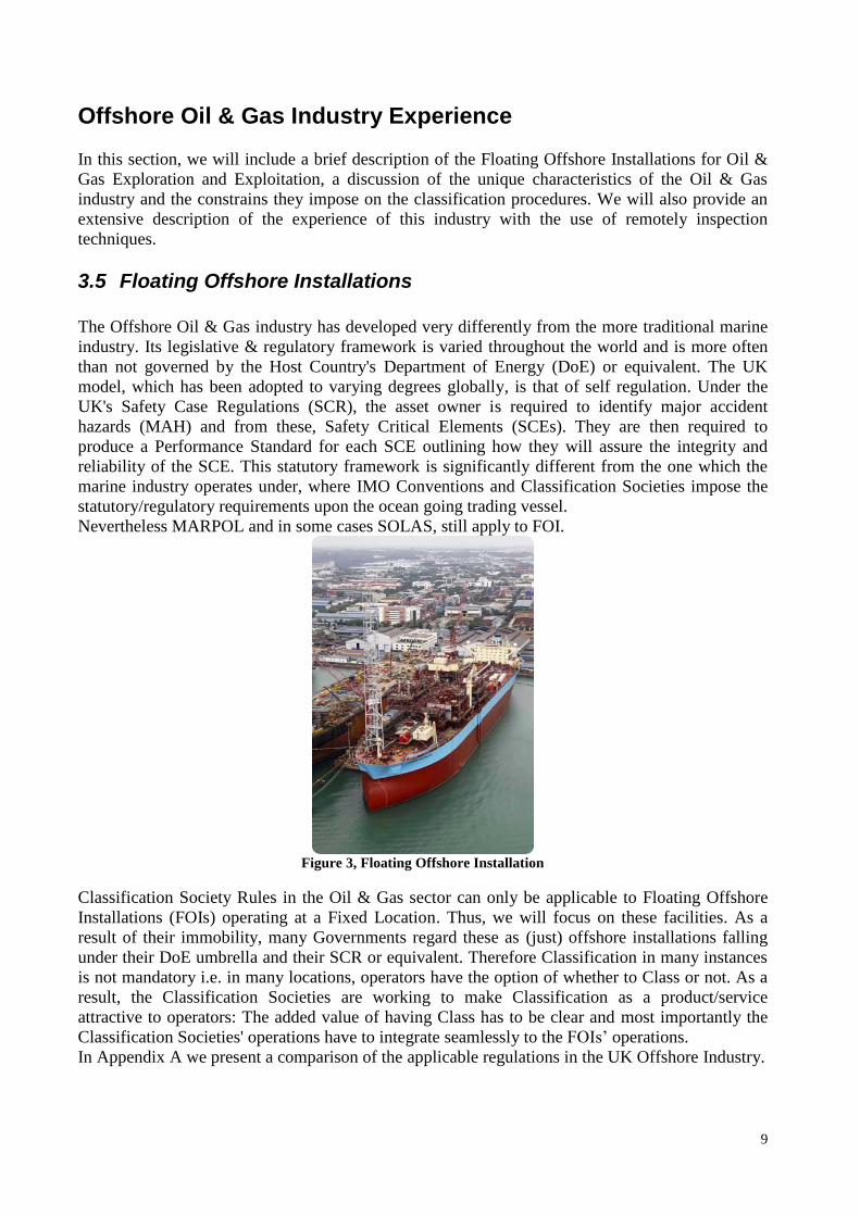
Nevertheless MARPOL and in some cases SOLAS, still apply to FOI.
Figure 3, Floating Offshore Installation
Classification Society Rules in the Oil & Gas sector can only be applicable to Floating Offshore
Installations (FOIs) operating at a Fixed Location. Thus, we will focus on these facilities. As a
result of their immobility, many Governments regard these as (just) offshore installations falling
under their DoE umbrella and their SCR or equivalent. Therefore Classification in many instances
is not mandatory i.e. in many locations, operators have the option of whether to Class or not. As a
result, the Classification Societies are working to make Classification as a product/service
attractive to operators: The added value of having Class has to be clear and most importantly the
Classification Societies' operations have to integrate seamlessly to the FOIs’ operations.
In Appendix A we present a comparison of the applicable regulations in the UK Offshore Industry.

10
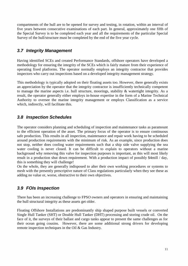
Figure 4, Floating Offshore Installation
3.6 Development of the Offshore Class
Classification Societies Rules currently are and will remain for the foreseeable future the only
suitable design and construction standards for FOIs, mainly because of the building yard's
familiarity with the Classification concept and its Rules. However, the offshore Oil & Gas Industry
has quite different operational expectations from the Marine Industry. Primarily, the Classification
Societies, which are major regulators of the Marine sector, don’t enjoy the same stature in the Oil
& Gas industry. Additionally, the prescriptive nature of the Class survey requirements doesn’t
blend well with the operational requirements of this industry and the significantly different
operational characteristics of the FOI with regards to sea going trading vessels.
Fundamental concept to the marine Classification procedure is the five years Special Survey
cycles, which are always carried out while the vessel is in drydock. The purpose of this concept is
that the ship’s conditions will be thoroughly assessed and all possible vessel’s defects/damages
will be properly repaired in order to re-issue the Class certificate.
Below we illustrate the fundamental differences of the FOIs with regards to. the sea going trading
vessels:
Ships FOIs
Must drydock every 5 yrs Never drydock
Has access to repair facilities Repairs carried out on location
Can repaint hull Cannot repaint hull
From the table above, it is immediately clear that this Class basis is fundamentally flawed for FOIs
since they are not afforded the luxury of regular drydocking. In fact, as intimated, the intent is the
complete opposite – never to drydock the vessel. This has led to the creation of Class Rules
specifically for the FOI that allow for a Continuous Survey program. In this program all
11
compartments of the hull are to be opened for survey and testing, in rotation, within an interval of
five years between consecutive examinations of each part. In general, approximately one fifth of
the Special Survey is to be completed each year and all the requirements of the particular Special
Survey of the hull/structure must be completed by the end of the five year cycle.
3.7 Integrity Management
Having identified SCEs and created Performance Standards, offshore operators have developed a
methodology for ensuring the integrity of the SCEs which is fairly mature from their experience of
operating fixed platforms. The operator normally employs an integrity contractor that provides
inspectors who carry out inspections based on a developed integrity management strategy.
This methodology is typically adopted on their floating assets too. However, there generally exists
an appreciation by the operator that the integrity contractor is insufficiently technically competent
to manage the marine aspects i.e. hull structure, moorings, stability & watertight integrity. As a
result, the operator generally either employs in-house expertise in the form of a Marine Technical
Authority to oversee the marine integrity management or employs Classification as a service
which, indirectly, will facilitate this.
3.8 Inspection Schedules
The operator considers planning and scheduling of inspection and maintenance tasks as paramount
to the efficient operation of the asset. The primary focus of the operator is to ensure continuous
safe production. This results in all inspection, maintenance and repair work having to be scheduled
around production requirements with the minimum of risk. As an example, since production does
not stop, neither does cooling water requirements such that a ship side valve supplying the sea
water cooling is never closed. It can be difficult to explain to operators without a marine
background why removing this valve for inspection purposes is important, as this will most likely
result in a production shut down requirement. With a production impact of possibly $4mill / day,
this is something they will challenge!
On the whole, they are generally indisposed to alter their own working procedures or systems to
mesh with the presently prescriptive nature of Class regulations particularly when they see these as
adding no value or, worse, obstructive to their own objectives.
3.9 FOIs Inspection
There has been an increasing challenge to FPSO owners and operators in ensuring and maintaining
the hull structural integrity as these assets get older.
Floating Offshore Installations are predominantly ship shaped purpose built vessels or converted
Single Hull Tanker (SHT) or Double Hull Tanker (DHT) processing and storing crude oil. On the
face of it, the surveys of their ballast and cargo tanks appear to present the same challenges as for
their ocean going cousins. However, there are some additional strong drivers for developing
remote inspection techniques in the Oil & Gas Industry.

12
FOIs generally remain on location for the life of field. Operational drivers are such that production
is, in the main, continuous. This results in these vessels not being globally gas free. Accordingly
much higher levels of safety are applied to all operational, maintenance and inspection aspects.
Unlike trading vessels, they are not afforded the luxury of drydocking. All surveys and repairs are
required to be carried out on location, some of which, such as the North Sea, are considered harsh
and as a result provide additional challenges. These challenges include the availability and
methods of repair and drives the Industry to a more risk based inspection regime whereby findings
impacting integrity (commonly known as anomalies within the industry) are assessed and a
monitoring inspection schedule devised. In some cases, this has resulted in annual inspection
being required in some tanks.
3.10 Present Class Status in Oil & Gas sector
Class Regulations presently require an exclusive Class surveyor to carry out the surveys.
However, as cargo and/or ballast tanks are not routinely scaffolded and the offshore industry
considers rafting too dangerous, Class surveyors are not in a position to comply with their own
regulations when carrying out close-up surveys, defined as "normally within reach of hand". It is
common practice for Rope Access Technicians (RATs) to scale structure, carry out inspections and
report findings to the Class surveyor.
The RATs more often than not are part of the contracted integrity inspection team permanently
onboard the asset. Consequently, the rope technicians may have no formal hull structural training.
As a result, Class Societies can feel exposed.
Production operations are such that, in general, only one cargo tank is usually taken out of
operation at any one time for inspection: The pre-survey isolation, gas freeing, cleaning and
subsequent inspection can take a tank out of operation for up to a month and has to be well planned
to minimise the impact on operations. The inspection team will normally consist of five
technicians. Where bed space is at a premium, this presents the operator with additional
challenges.
In some jurisdictions Class is not a requirement for FOIs. However the hull structure and tank
integrity never-the-less require to be assured. This has permitted the operators of FOIs to
investigate alternative means of inspection and as a result of the safety and operational drivers, the
industry has already begun to employ ROV technology for tank inspections.
13
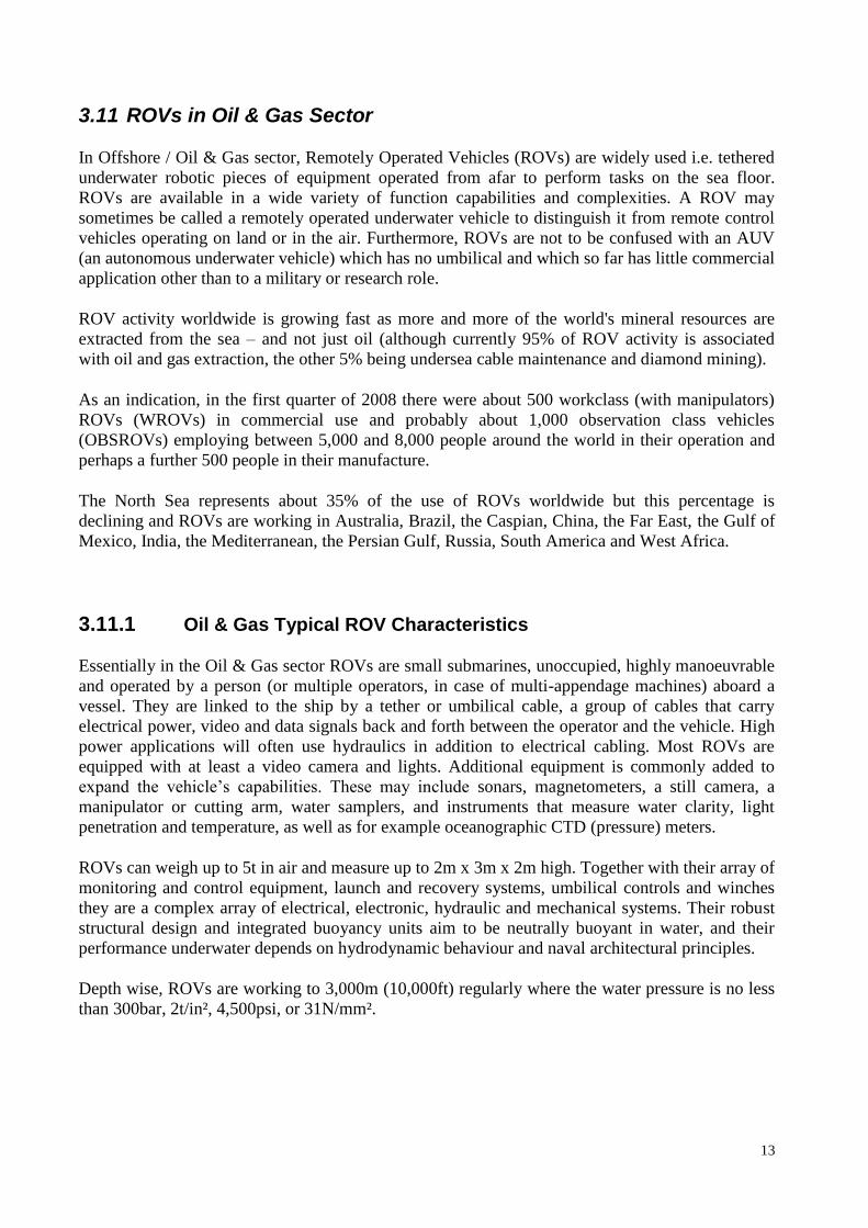
3.11 ROVs in Oil & Gas Sector
In Offshore / Oil & Gas sector, Remotely Operated Vehicles (ROVs) are widely used i.e. tethered
underwater robotic pieces of equipment operated from afar to perform tasks on the sea floor.
ROVs are available in a wide variety of function capabilities and complexities. A ROV may
sometimes be called a remotely operated underwater vehicle to distinguish it from remote control
vehicles operating on land or in the air. Furthermore, ROVs are not to be confused with an AUV
(an autonomous underwater vehicle) which has no umbilical and which so far has little commercial
application other than to a military or research role.
ROV activity worldwide is growing fast as more and more of the world's mineral resources are
extracted from the sea – and not just oil (although currently 95% of ROV activity is associated
with oil and gas extraction, the other 5% being undersea cable maintenance and diamond mining).
As an indication, in the first quarter of 2008 there were about 500 workclass (with manipulators)
ROVs (WROVs) in commercial use and probably about 1,000 observation class vehicles
(OBSROVs) employing between 5,000 and 8,000 people around the world in their operation and
perhaps a further 500 people in their manufacture.
The North Sea represents about 35% of the use of ROVs worldwide but this percentage is
declining and ROVs are working in Australia, Brazil, the Caspian, China, the Far East, the Gulf of
Mexico, India, the Mediterranean, the Persian Gulf, Russia, South America and West Africa.
3.11.1 Oil & Gas Typical ROV Characteristics
Essentially in the Oil & Gas sector ROVs are small submarines, unoccupied, highly manoeuvrable
and operated by a person (or multiple operators, in case of multi-appendage machines) aboard a
vessel. They are linked to the ship by a tether or umbilical cable, a group of cables that carry
electrical power, video and data signals back and forth between the operator and the vehicle. High
power applications will often use hydraulics in addition to electrical cabling. Most ROVs are
equipped with at least a video camera and lights. Additional equipment is commonly added to
expand the vehicle’s capabilities. These may include sonars, magnetometers, a still camera, a
manipulator or cutting arm, water samplers, and instruments that measure water clarity, light
penetration and temperature, as well as for example oceanographic CTD (pressure) meters.
ROVs can weigh up to 5t in air and measure up to 2m x 3m x 2m high. Together with their array of
monitoring and control equipment, launch and recovery systems, umbilical controls and winches
they are a complex array of electrical, electronic, hydraulic and mechanical systems. Their robust
structural design and integrated buoyancy units aim to be neutrally buoyant in water, and their
performance underwater depends on hydrodynamic behaviour and naval architectural principles.
Depth wise, ROVs are working to 3,000m (10,000ft) regularly where the water pressure is no less
than 300bar, 2t/in², 4,500psi, or 31N/mm².
14
3.11.2 Oil & Gas Typical ROV Usage
ROVs can perform just about all underwater tasks that divers do but they do it deeper, safer and in
most cases cheaper. Practically, divers are still used for dextrous (non observation) underwater
activities in shallow water, where they can compete on price and effectiveness. But they cannot be
used below about 200m (in UK and Norway this is the legal limit) and an increasing percentage of
oil and gas exploration activity around the world is happening in deep water of deeper than 200m.
Construction of production facilities and their maintenance obviously follows.
In exploration mode, ROVs do all the subsea work required to support a drilling programme off
floating drilling rigs – much of this is observation work but the vehicles may be required to change
out equipment that the drillers have to put on the seabed (like blowout preventers stacks), or
recover debris, so WROVs are used as well. On jackups (drilling rigs which sit on the seabed),
there is little requirement for any underwater intervention so ROVs are not generally used except
in strong current areas like the southern North Sea where the legs and spud cans of the jackups are
subject to scour, so they have to be regularly inspected.
When oil or gas is discovered, the drilling rig will often go into development mode where more
wells are drilled and often tied into a production manifold to be used at some future date for subsea
production either via an export pipeline or connected locally to another platform. Here, the ROV is
used with torque and other tools to pull in flow lines or control umbilicals and operate valves. This
is needed both on floating and non-floating .
When the production facilities are installed, be they platforms, subsea manifolds, pipelines or
Floating Production Storage and Offloading (FPSOs), again there is a substantial requirement for
ROVs to assist. The whole seabed area needs to be surveyed prior to, and after, installation,
pipeline touchdown needs monitoring, lift wires / ropes need attaching or detaching, valves need
turning, pipelines need burial or another form of protection. It is a demanding workplace where
dual large WROVs have really come into their own in recent years.
Finally, there is the production phase – here again there is both inspection and maintenance to do,
increasingly the preserve of ROVs of all shapes and sizes. For inspection of pipelines WROVs
fitted with diverse sensors, like pipe-trackers and multibeam sonars, are used, whereas for
platforms or subsea production facilities OBSROVs fitted with cameras, cathodic protection
probes and other sensors, such as flooded member detection probes, provide a complete analysis to
owners regarding of the requirement for preventative or other maintenance.
For maintenance, both OBSROVs and WROV have their role – it is amazing what small ROVs
with the use of proprietary tooling can do to assist with the change out of subsea modules and
other types of repair and maintenance, but this is mostly the job of WROVs with their
manipulative capability.
Other roles for ROVs, are cable installation / maintenance, mining or wreck recovery, or
controlling sledges and ploughs to trench subsea pipelines and umbilicals or steering fall pipes to
fill in trenches or provide cover with stones.
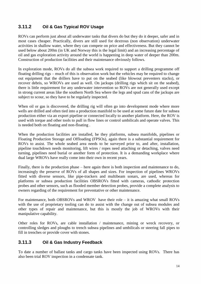
3.11.3 Oil & Gas Industry Feedback
To date a number of ballast tanks and cargo tanks have been inspected using ROVs. There has
also been trial ROV inspection in a condensate tank.
15
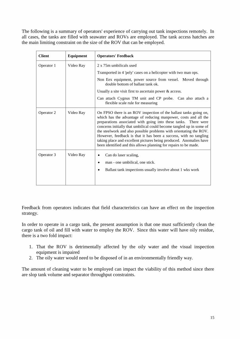
The following is a summary of operators' experience of carrying out tank inspections remotely. In
all cases, the tanks are filled with seawater and ROVs are employed. The tank access hatches are
the main limiting constraint on the size of the ROV that can be employed.
Client Equipment Operators' Feedback
Operator 1 Video Ray 2 x 75m umbilicals used
Transported in 4 'pely' cases on a helicopter with two man ops.
Non Eex equipment, power source from vessel. Moved through
double bottom of ballast tank ok.
Usually a site visit first to ascertain power & access.
Can attach Cygnus TM unit and CP probe. Can also attach a
flexible scale rule for measuring
Operator 2 Video Ray On FPSO there is an ROV inspection of the ballast tanks going on,
which has the advantage of reducing manpower, costs and all the
preparations associated with going into these tanks. There were
concerns initially that umbilical could become tangled up in some of
the steelwork and also possible problems with orientating the ROV.
However, feedback is that it has been a success, with no tangling
taking place and excellent pictures being produced. Anomalies have
been identified and this allows planning for repairs to be made.
Operator 3 Video Ray Can do laser scaling,
man - one umbilical, one stick.
Ballast tank inspections usually involve about 1 wks work
Feedback from operators indicates that field characteristics can have an effect on the inspection
strategy.
In order to operate in a cargo tank, the present assumption is that one must sufficiently clean the
cargo tank of oil and fill with water to employ the ROV. Since this water will have oily residue,
there is a two fold impact:
1. That the ROV is detrimentally affected by the oily water and the visual inspection
equipment is impaired
2. The oily water would need to be disposed of in an environmentally friendly way.
The amount of cleaning water to be employed can impact the viability of this method since there
are slop tank volume and separator throughput constraints.

16
4 Proposals
In this section we will present the procedural guidelines of how robotic inspection of ships’ hull
could be performed.
We will also present the procedures for the amendment of existing Rules and/or issue of new Rules
by RINA and Lloyd’s Register.
4.1 Procedural guidelines for the acceptance of robotic inspection of ships’ hull
In order to propose procedural guidelines for how robotic inspection of ships’ hull could be
performed we must consider the experience of the Oil & Gas industry with ROVs. This
experience, as presented in Section 0, confirms that remote inspection techniques can and must be
integrated into the survey procedure.
Regarding the actual procedural guidelines we may just refer to IACS Recommendation No.42
where it is stated that “Remote Inspection Technique methods may be used to facilitate the
required internal examinations, including close-up surveys and gaugings required with close-up
surveys”. The recommendation mentions nothing regarding the nature of the methods, so robotic
ones may be used. Additionally, it does mention that: “The methods applied for Remote Inspection
Techniques are to provide the survey results normally obtained for the Surveyor”. Thus if the
robotic inspection of the ship’s hull can produce results that satisfy the Surveyor then it can be
accepted. The rest of the IACS Recommendation No.42 provides the rest of the necessary
procedural guidelines. In this point we have to include the additional constrains posed by IACS
PRs No. 19 regarding thickness measurements when they are carried out by robots.
4.2 Draft Inspection Procedure
4.2.1 General
Remote Inspection Technique methods with the employment of robots may be used to facilitate the
required examinations, including close-up surveys and gauging required with close-up surveys.
The methods applied for Remote Inspection Techniques are to provide the survey results normally
obtained by the Surveyor.
Confirmatory close-up surveys are to be carried out by the Surveyor at selected locations where
close up surveys are required to verify the results of the Remote Inspection Technique methods.
Proposals for use of Remote Inspection Technique methods are to be submitted to the
Classification Society for approval in advance of the survey. The Classification Society will
review the proposal and approve the arrangements including minimum requirements for
confirmatory close-up surveys.
17
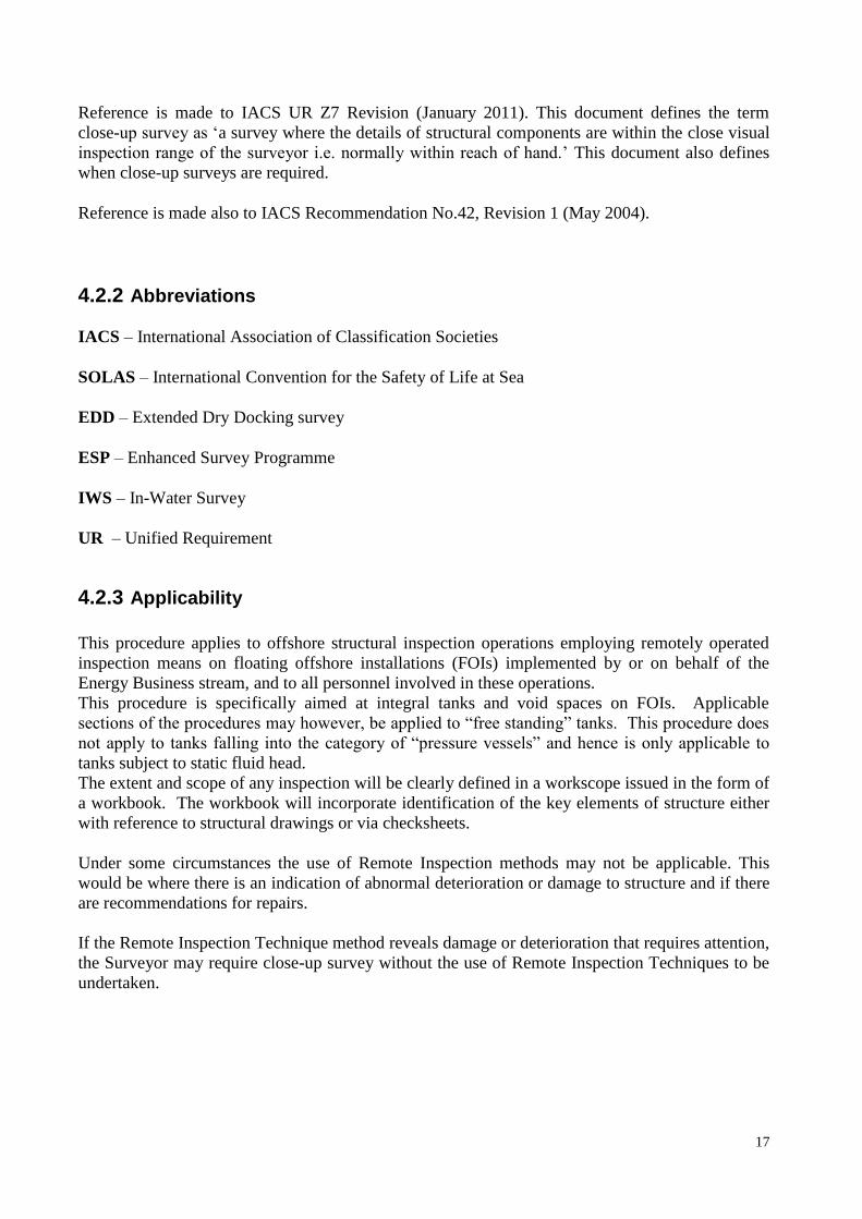
Reference is made to IACS UR Z7 Revision (January 2011). This document defines the term
close-up survey as ‘a survey where the details of structural components are within the close visual
inspection range of the surveyor i.e. normally within reach of hand.’ This document also defines
when close-up surveys are required.
Reference is made also to IACS Recommendation No.42, Revision 1 (May 2004).
4.2.2 Abbreviations
IACS – International Association of Classification Societies
SOLAS – International Convention for the Safety of Life at Sea
EDD – Extended Dry Docking survey
ESP – Enhanced Survey Programme
IWS – In-Water Survey
UR – Unified Requirement
4.2.3 Applicability
This procedure applies to offshore structural inspection operations employing remotely operated
inspection means on floating offshore installations (FOIs) implemented by or on behalf of the
Energy Business stream, and to all personnel involved in these operations.
This procedure is specifically aimed at integral tanks and void spaces on FOIs. Applicable
sections of the procedures may however, be applied to “free standing” tanks. This procedure does
not apply to tanks falling into the category of “pressure vessels” and hence is only applicable to
tanks subject to static fluid head.
The extent and scope of any inspection will be clearly defined in a workscope issued in the form of
a workbook. The workbook will incorporate identification of the key elements of structure either
with reference to structural drawings or via checksheets.
Under some circumstances the use of Remote Inspection methods may not be applicable. This
would be where there is an indication of abnormal deterioration or damage to structure and if there
are recommendations for repairs.
If the Remote Inspection Technique method reveals damage or deterioration that requires attention,
the Surveyor may require close-up survey without the use of Remote Inspection Techniques to be
undertaken.
18
4.2.3.1 Remotely Operated Vehicles (ROVs)
Implicit within this procedure is the assumption that the tank under inspection is full of seawater
and the means of inspection will be via a ROV attached by an umbilical to a control station and
operator.
Alternative and/or novel approaches will be deemed acceptable provided they meet the intent of
this procedure.
4.2.4 Objective
To provide parameters and requirements for remote vehicle operators in carrying out structural
inspections and the reporting there-of.
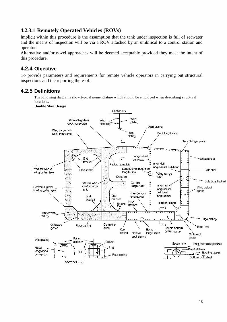
4.2.5 Definitions The following diagrams show typical nomenclature which should be employed when describing structural
locations.
Double Skin Design
19
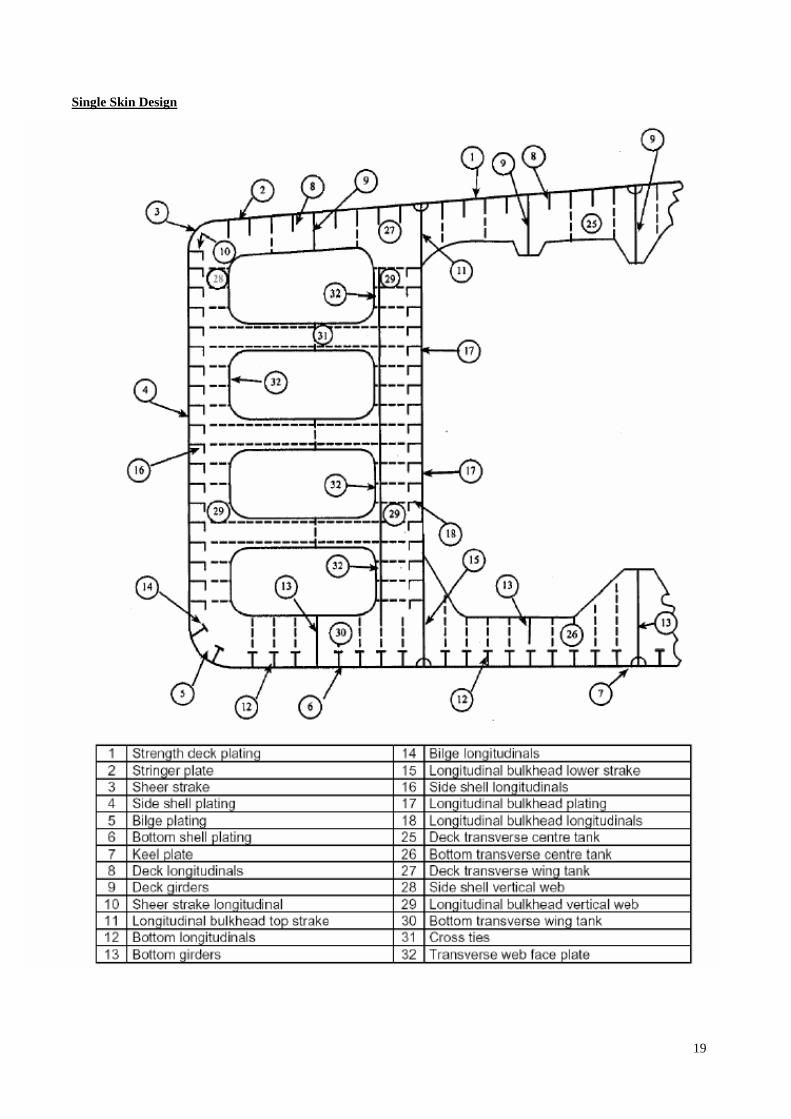
Single Skin Design

20
4.2.6 Responsibilities
4.2.6.1 Offshore Inspection Engineer
The offshore inspection engineer (OIE) is either a permanent offshore staff member or a
temporarily assigned, competent person, mobilised in order to manage inspection activities and is
responsible for ensuring the requirements of this procedure are applied within the scope of the
inspection to be carried out.
The OIE is responsible for ensuring all inspection and reporting requirements are communicated to
the relevant ROV operator personnel and are complied with in accordance with this procedure.
4.2.6.2 ROV Operator/s
The ROV operator/s is responsible for providing and operating the requisite equipment in section
4.2.7 to safely carry out a remote structural inspection in compliance with this procedure. He must
ensure that the equipment provided has been fully serviced and correctly calibrated.
A minimum of one ROV operator will hold a valid CSWIP 3.3U certificate plus a valid Hull
Inspection Certificate (to be developed = currently not exisiting.).
The ROV operator/s will be employed by an LR approved service supplier.
4.2.7 Inspection Equipment
The following inspection equipment is to be available and fully functional. Where indicated,
service certification is to be made available for confirmation by the OIE.
Remotely operated vehicle
Umbilical with suitable connections to ROV and control hub / power supply
Control console
Power supply connections
Suitable illumination device
Camera
Ultrasonic Thickness-gauging (UT) Probe
Alternating Current Field Measurement (ACFM) Probe
Measuring Device
Marking device
4.2.7.1 Remotely Operated Vehicle
The ROV must be capable of the following functions:
Navigating through 400 x 600 mm access holes
Operating with a suitable illumination device
Operating with a video camera
Carrying out thickness gauging using a UT probe
Carrying out ACFM using an ACFM probe
Measuring defect sizes
Marking defect locations
Depth rating not less than 50m

21
4.2.7.2 Umbilical
A typical double skinned FOI could have common wing and double bottom water ballast tanks
some 50m long, 30m wide and 30m deep. Accordingly the umbilical should be capable of
reaching 150m. Umbilicals of shorter length will be acceptable provided all locations within the
tank under inspection are reachable.
4.2.7.3 Control Console
The control console and equipment within should be suitably waterproof and 'Ex' rated (e.g. IP67)
such that the equipment has no spark potential.
4.2.7.4 Monitor
A suitable monitor with screen size no less than 5"
4.2.7.5 Video Overlay
A provision to overlay date, time and depth should be provided.
4.2.7.6 Data Recording
A provision for recording the inspection video should be provided.
A provision to overlay a voice recording during the inspection should be provided.
4.2.7.7 Power
The power should be supplied via the available mains system such that the inspection can be of a
continuous nature where possible. Power requirements of 100 – 240 vac at 50/60 Hz have been
found to be suitable.
4.2.7.8 Suitable Illumination Device
Successful operations have shown that 40 W of illumination is acceptable.
4.2.7.9 Camera
The video camera should have a still photo image facility with minimum resolution capability of
550 x 0.1lux.
4.2.7.10 UT Probe
A suitable LR type approved underwater UT probe capable of attachment to the ROV should be
available for use.
4.2.7.11 ACFM Probe
In order to evaluate surface defects, a suitable LR type approved underwater ACFM probe capable
of attachment to the ROV should be available for use.
4.2.7.12 Measuring Device
A mechanical or optical (laser) device from which defect sizes can be measured should be
available for use.
A depth measurer to evaluate pitting should be available for use.

22
4.2.7.13 Marking Device
A capability to identify and return to a specific location is imperative. Whilst it is appreciated that
this is most readily achieved through the skill of the operator, it is considered that a method of
marking the location of a defect should be available for use.
4.2.7.14 Communications requirements
Two-way communication between the Surveyor and technician who operate the robots is to be
provided.
4.2.8 Safety Requirements
The ROV operator shall ensure that he is familiar with the contents of MS20-02-105, Project
Emergency Response Procedure and relevant means from LR’s HS&E suite of Safe Methods of
Work.
4.2.8.1 Personal Protective Equipment
The ROV operator shall ensure that he is suitably equipped with the following personal protective
equipment as a minimum:
Coverall
Hard hat
Ear defenders
Gloves
Steel toe-capped boots
Suitable eye protection
4.2.8.2 Risk Assessment
A risk assessment shall be undertaken for all activities associated with the inspection of tanks.
When possible this should be undertaken in consultation with regular crew. Further information
can be found in the following document: LR Safe Method at Work 040 – Risk Assessment.
4.2.8.3 Survey meeting
Prior to the commencement of the Survey, a meeting is to be held between the attending
Surveyor(s), the Owner’s/Operator’s representative in attendance, the technicians who control the
robots and the Master of the ship or an appropriately qualified representative appointed by the
Master or Owner/Operator, so as to ensure the safe and efficient conduct of the survey and
thickness measurements to be carried out.
Communication with the qualified technicians firm and Owner/Operator is to be agreed during the
meeting, with respect to the reporting of thickness measurements on a regular basis and the prompt
notification of the attending Surveyor(s) in case of findings, including excessive and/or extensive
corrosion or pitting/grooving of any significance, structural defects like buckling, fractures and
deformed structures, detached and/or holed structure and corrosion of welds.
A record is to be kept of when and where the meeting took place, along with the names of those
who attended.
Deployment of robots in areas with personnel/crew in close proximity
o potential obstacles,
o increased hazards from falling equipment,

23
o blocking escape routes, etc.
Deployment of robots in hazardous atmosphere
o Intrinsically safe
o Atmospheric tests to prevent deterioration to robotic equipment
Wear and abrasion to the ship structure and/or coating
Emergency shut-down of the robotic equipment
o How to signal (all) robots to stop moving or turn-off
o Secondary line of communication between technician and robotic fleet for
emergencies
Emergency communication channels between ship’s safety staff and robotic technicians
Evidence of calibration for robotic equipment or calibration plan
4.2.8.3.1 Considerations of Hazards
Spaces which are required to be examined for the said Survey are to be cleared and cleaned as
considered necessary by the Surveyor and this may require the removal of sludge, sediment and
scale in order to carry out the survey to the required standard and determine the extent of any
corrosion which may be present.
Where salt water ballast spaces and cargo spaces are required to be examined, the preparation for
survey is to be of a similar standard and extent as that required for Special Survey.
4.2.8.3.2 Route planning

24
The structure to be examined using Remote Inspection Technique methods is to be sufficiently
clean to permit meaningful examination. Tanks are to be thoroughly cleaned including removal,
from tank internal surfaces, of all loose accumulated corrosion scale, if present.
4.2.9 Site Requirements
All Client site specific requirements, including the Permit to Work System are to be fully complied
with.
4.2.10 Inspection
Option a) The inspection scope will be governed by a workbook reviewed and
approved by LR.
Option b) The inspection scope will be governed by a workbook issued by LR
The workbook will contain the following:
Comprehensive structural drawings of the tank to be inspected
A clearly defined ROV inspection route
Locations where thickness gauging is to be carried out
Locations to be given special attention and the extent of this
Locations where ACFM is to be carried out
The ROV operator shall not deviate from the workbook inspection route without giving specific
reasons there for.
4.2.10.1 Narrative
Throughout the inspection, a narrative should be recorded confirming the present location and
providing an assessment on the structural condition, coating condition and corrosion condition in
accordance with the guidance given in section 4.2.12.3 of this procedure.
A time stamp of any anomalous finding as defined by the guidance given in section 4.2.12.3 of this
procedure should be raised.
4.2.11 Reporting
The reporting deliverables required are:
The video with date, time and narrative overlay
The workbook - The drawings should be annotated by the ROV operator indicating the
location and video time stamp of any anomalous condition which was identified.
Identified photo stills – to be incorporated into the workbook
4.2.12 Assessment Criteria
The inspector shall apply the following assessment criteria to report his findings.
4.2.12.1 Structural Criteria
Structural damage shall be reported by employing the following guidelines:
25
Cracks /
Fractures
All cracks / fractures shall be considered anomalous and reported in terms of location, point
of origin, length, depth, breadth (as can be determined), direction of propagation, proximity
to primary structural elements (tank boundary plating, transverse frames etc). The OIE shall
be informed in order to determine the extent of NDE to be performed to further investigate
the cause and / or to recommend immediate repair.
Physical
Damage
All evidence of distortion, buckling or deformation shall be considered anomalous and
reported in terms of location, affected components and extent.
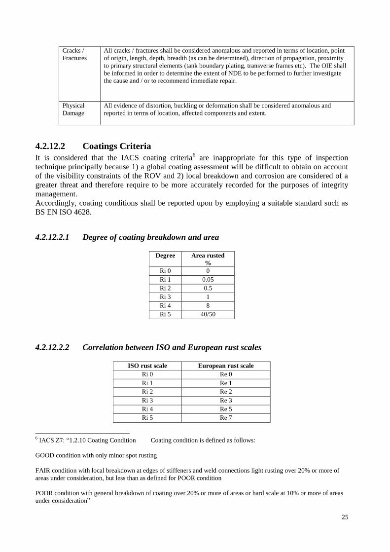
4.2.12.2 Coatings Criteria
It is considered that the IACS coating criteria6 are inappropriate for this type of inspection
technique principally because 1) a global coating assessment will be difficult to obtain on account
of the visibility constraints of the ROV and 2) local breakdown and corrosion are considered of a
greater threat and therefore require to be more accurately recorded for the purposes of integrity
management.
Accordingly, coating conditions shall be reported upon by employing a suitable standard such as
BS EN ISO 4628.
4.2.12.2.1 Degree of coating breakdown and area
Degree Area rusted
%
Ri 0 0
Ri 1 0.05
Ri 2 0.5
Ri 3 1
Ri 4 8
Ri 5 40/50
4.2.12.2.2 Correlation between ISO and European rust scales
ISO rust scale European rust scale
Ri 0 Re 0
Ri 1 Re 1
Ri 2 Re 2
Ri 3 Re 3
Ri 4 Re 5
Ri 5 Re 7
6 IACS Z7: “1.2.10 Coating Condition Coating condition is defined as follows:
GOOD condition with only minor spot rusting
FAIR condition with local breakdown at edges of stiffeners and weld connections light rusting over 20% or more of
areas under consideration, but less than as defined for POOR condition
POOR condition with general breakdown of coating over 20% or more of areas or hard scale at 10% or more of areas
under consideration”

26
4.2.12.2.3 Approximate correlation between ISO and ASTM rust scales
ISO rust scale ASTM D 610
Ri 0 10
Ri 1 9
Ri 2 7
Ri 3 6
Ri 4 4
Ri 5 1 to 2
4.2.12.2.4 Correlation between ISO and ASTM rating systems for blisters
Density Size
ASTM ISO ASTM ISO
None 0
(less than few) 1 (smaller than 8) 1
Few 2 8 2
Medium 3 6 3
Medium – Dense 4 4 4
Dense 5 2 5
4.2.12.3 Corrosion Criteria
The type and extent of corrosion shall be reported by employing a suitable standard such as BS EN
ISO 4628.
4.2.12.3.1 Intensity of deterioration
Rating Intensity of change
0 unchanged, i.e. no perceptible change
1 very slight, i.e. just perceptible change
2 slight, i.e. clearly perceptible change
3 moderate, i.e. very clearly perceptible change
4 considerable, i.e. pronounced change
5 sever, i.e. intense change
4.2.12.3.2 Quantity of defects
Rating Quantity of defects (relative to a test area of 1 to 2 dm2)
0 none, i.e. no detectable defect
1 very few, i.e. some just significant defects
2 few, i.e. small but significant amounts of defects
3 moderate, i.e. medium amount of defects
4 considerable, i.e. serious amount of defects
5 dense, i.e. dense pattern of defects

27
4.2.12.3.3 Size of defects
Rating Size of defects
0 not visible under x 10 magnification
1 only visible under magnification up to x 10
2 just visible with normal corrected vision
3 clearly visible with normal corrected vision(up to 0,5 mm)
4 range 0,5 to 5 mm
5 larger than 5 mm
4.2.12.4 Fixtures & Fittings Criteria
Damage found to fixtures and fittings shall be reported by employing the following guidelines:
All pipes, valves, suction
strums & supports
Defects / damage likely to affect the operation of the piping system
function shall be considered anomalous and be reported.
Access ladders, landings,
spider decks, handrails
Defects / damage affecting the safe access to / from / within the tank shall
be considered anomalous and be reported.
Access issues Reports shall define the extent to which access for each of the required
inspection activities could not be facilitated.
Silt, sand & sludge Reports of residual sand/silt/sludge shall specify extent of affected area and
depth, as well as some indication of the condition of the tank coating /
structure under.

28
4.2.13 Appendix - Approval of ROV Inspection Services
Requirements for approval
Suppliers that demonstrate the experience and capability necessary to carry out a thickness survey
will be considered for approval if they comply with the following: Training of Personnel
A documented training programme for thickness measurement personnel should be in place.
Where it is not possible to perform this internally, a programme of external training may be
accepted.
Personnel at operator and supervisor grades are to be qualified in accordance with a recognised
national or international industrial standard such as EN 473, SNT-TC-1A, ISO 9712 or equivalent.
Operators are to be certified to a minimum of level I, supervisors to a minimum of level II.
Operators should have had a minimum of one year tutored training on board ship and have enough
knowledge of ship structures to be able to select a representative position for each measurement.
Supervisors should have had a minimum of two years experience as operator/technician/inspector
involved with the thickness measurement of ship structural material. Supervision
The supplier shall provide supervision for all services supplied. For a supplier consisting of one
person, that person shall meet the requirements of a supervisor. Personnel Records
A list of qualified personnel including details of formal education, training and experience must be
maintained up to date and be available for scrutiny by the attending surveyor.
Supervisors and operators are to carry ID cards (with photographs) showing NDE qualifications
and authorisation to work on thickness measurement surveys and shall include a photograph of
sufficient size and detail as to identify the operator Equipment
Suppliers must possess equipment that is capable of giving accurate readings of material thickness.
Where measurements are to be taken through protective coatings the equipment must be capable of
using the multiple echo technique in order that coatings are discounted from the displayed
readings.
'A scan' flaw detectors, multiple echo direct reading gauges or a combination of both may be used
for this purpose. Equipment must be maintained and calibrated regularly in accordance with a
documented procedure and the status of calibration is to be displayed on each piece of equipment.
The range of materials, thicknesses, surface conditions and protective coatings upon which the
equipment can be used must be stated, together with the tolerances on accuracy of measurement
that can be expected. Instructions for the safe and effective operation of the equipment must be
available to all operators. Quality Assurance System
Suppliers are required to have a documented system which covers at least the following items:
a) survey preparation (equipment required, surface preparation, preservation of protective
coatings, checklists, etc.)
b) maintenance, calibration and operation of equipment
c) Safety requirements
d) code of conduct to be observed by employees
e) training programmes for personnel
f) the method and degree of supervision and verification to be applied
g) survey recording and reporting
h) periodic review of work process procedures, complaints, corrective actions, and issuance,
maintenance and control of documents
i) quality management of subsidiaries and branches
29
The documented system should be approved and endorsed by the company personnel
A documented Quality Assurance system complying with the ISO 9000 standard or equivalent and
including the above items, would be considered acceptable
30
4.3 Roadblocks
As laid out previously the document does proposed ships’ survey procedures.
It can be seen that this document proposes two changes to existing methods:
a) a Hull Inspection Certificate
b) different criteria for coating condition other than IACS Z7: namely, :BS EN ISO 4628.
a) is a document which would need to be developed with appropriate criteria
b) would require IACS to reconsider its criteria.
In order for a survey procedure of this kind to be implemented, these issues would need resolution.

31
5 Description of RINA / LR management process for technical Rules
In this section the procedures provided by RINA and LR for amendments to existing rules and/or
issuing of new rules are described. Error! Reference source not found. and Error! Reference
source not found. show the flow chart of the management process, which is described in the
following paragraphs. In particular cases, new or modified rules may be issued through Rule
Variations, i.e., documents which are valid as technical rules during the approval procedure.
5.1 Technical rules issued by RINA
Technical rules issued by RINA for the marine sector are classified as follows:
- Rules for the classification of ships (containing requirements whose enforcement is
compulsory for the purpose of classification and provisions for the assignment of additional
class notations)
- Rules for ships and special units (containing requirements whose enforcement is
compulsory for the purpose of classification)
- Complementary rules (containing requirements which are to be satisfied in order to certify
products, systems, etc. or to assign additional class notations)
- Rules for the application of governmental regulations (containing provisions issued by
RINA relating to duties that it carries out on behalf of Administrations)
- Guides (containing requirements given for guidance purposes)
5.2 Technical rules issued by LR
Overall, LR follows a similar structure to the above with regards to Rules and Guidance Notes.
LR’s current and active Marine Rules are as follows:
Rules:
Rules and Regulations for the Classification of Ships
Rules for the Manufacture, Testing and Certification of Materials
Rules and Regulations for the Classification of Special Service Craft
Rules and Regulations for the Classification of Naval Ships
Rules and Regulations for the Construction and Classification of Ships for the Carriage of
Liquefied Gases in Bulk
Rules and Regulations for the Construction and Classification of Ships for the Carriage of
Liquid Chemicals in Bulk
Rules and Regulations for the Classification of Inland Waterways Ships
Code for Lifting Appliances in a Marine Environment
Rules and Regulations for the Classification of Linkspans
Rules for the Classification of Trimarans
Rules and Regulations for the Classification of Ships on the Great Lakes and River St.
Lawrence
Provisional Rules:
Provisional Rules for Ergonomic Container Lashing
Provisional Rules for the Winterisation of Ships

32
Technical Background for Provisional Rules for the Winterisation of Ships
Provisional Rules for the Classification of Methane Gas Fuelled Ships
Provisional Rules for the Application of Sandwich Panel Construction to Ship Structure
Provisional Rules for the Classification of Wing in Ground Effect Craft
Provisional Rules for Existing Ships
Provisional Rules for Launch and Recovery Appliances for Survival Craft and Rescue
Boats
Provisional Rules for the Classification of Potable Water Carriers
Provisional Rules for the Construction and Classification of Submarine Pipelines
Provisional Rules for Sail-Assisted Ships
Provisional Rules for the Classification of Ship Event Analysis Systems
Provisional Rules for the Construction and Classification of Offshore Well Stimulation
Ships
Guidance Notes:
Guidance Notes and Requirements for the classification of Air Cushion Vehicles (ACV)
Naval Survey Guidance for Steel Ships
As can be noticed from the above list, as a general guide LR has Rules, Provisional Rules and
Guidance Notes. Regarding the requirements to certify products, these are generally incorporated
into the Rules and therefore there is no need for “Complementary Rules”. If the detail is not in the
Rules there is probably a reference to the relevant document. For example, take a product in a
given material, if the material requirement is not in the Rules, the Rules will probably reference the
MQPS or the MSPM.
Also, regarding the rules for the application of governmental regulations, LR Rules incorporate
regulations from IMO, IACS, etc. However, flag-related requirements are not in the Rules and LR
has no specific Rules relating to them.
Finally, regarding Guides or the LR equivalent of Guidance Notes, LR Provisional Rules could
also fall under this category, as in essence they are guidance and any notations within the
Provisional Rules are non-mandatory.
5.3 Proposals for additions or amendments to rules
In RINA, requests for amendments to existing rules and/or issuing of new rules may come from
internal proposals (following research, experience, comments, etc) or from external contributions
(for instance external rules, comments provided by the customers, etc).
Similarly, in LR, both internal and external feedback is captured. At this stage, LR also captures
mandatory instruments (mainly from IMO and IACS), fed in from External Affairs, a department
of Lloyd’s Register, Marine.
In RINA, each request is assessed by the appropriate Technical Organizational Unit (Technical
OU), i.e. an organizational unit responsible for the research, development and maintenance of
technical rules. The proposals that are considered acceptable are collected by the Normative
Affairs Section (NORS) and included in the Rule updating program.
33
In the same way, in LR Rules Impact Assessment Meetings are been held with technical authors
from the different disciplines responsible for the research, development and maintenance of
Marine Rules. As described, the “proposals” or “instruments” considered acceptable are assigned
to a relevant technical author. All assessments are logged onto the Rules Workflow Tool, which
seems to be the equivalent of the “Rule updating program” described above.
5.4 Rule updating program
For RINA, the Rule updating program lists the requests for the issue of new rules or amendments
to existing ones. Every year it is prepared by the Normative Affairs Section and submitted to the
Director of the Marine Division for approval.
Similarly, LR prepares reports from the Rules Workflow Tool on Rule change workload, however,
the main difference is that this is not submitted for approval.
5.5 Draw up of the proposal
In RINA, the draw up of the proposal is carried out by the appropriate Technical OU, while in LR
this is the Technical Author in the appropriate discipline, taking into account the Rule Variations
or Rule Interpretations previously issued and intended to be introduced in the technical rules;
external rules (such as governmental regulations, agreements, codes, international rules, rules
issued by IACS, etc) are also considered.
In LR however, the external rules are initially considered in 1.2 Proposals for additions or
amendments to rules but they are incorporated into Proposals at this stage. Appropriate LR experts
are consulted if required.
In RINA, the draft of the proposal is sent to the Normative Affairs Section for checking that it is
consistent in structure and compatible with other existing rules.
This is understood to be the equivalent of the initial checks carried out in LR, Marine Product
Development (MPD) Support, once a Proposal has been prepared by the relevant Technical author
(e.g. checking associated Forms and Proposals for consistency and compatible with existing
Rules).
In RINA, subject to the satisfactory outcome of this examination, the NORS prepares a document
to be sent to the appropriate Groups of Experts and/or to the Technical Committee. Representatives
of Administrations are allowed to participate to the Rule development, viewing and commenting
the documents and information exchanged with the Technical Committee. Their comments are
taken into account in the preparation of the final versions.
In LR however, all Proposals are initially approved internally through a chain of command up to
the Marine Director. Once approved, Proposals are disseminated to the Technical Committee and
the Regional Technical Committees. The members of the Technical Committee and the Regional
Technical Committees participate in the Rule development by viewing, questioning and
commenting on Proposals. Technical authors are required to comment on feedback received and, if
required, act to modify Proposals. A document with comments (from Technical Committee and the
Regional Technical Committee members) and replies (from LR) is published and disseminated.
Then the external approval process can move forward.

34
5.6 Review and approval
In RINA, the draft of the proposal is generally reviewed by the Group of Experts, whose members
are appointed by the Director of the Marine Division and are chosen among technicians with
particular competence and experience in RINA marine activities.
In LR, this is the equivalent chain of command for the initial approval internally (see the first
sentence in the paragraph above).
The review by the Groups of Experts is not required, if the proposal concerns rules for which
RINA has already acquired experience of application or deriving from external rules.
Any Experts’ comments are assessed by the Technical OU and the proposal is eventually amended.
The Normative Affairs Section sends the final document to the Technical Committee, which
consists of eleven members appointed every four years by board of directors of Registro Navale
Italiano and chosen for their technical competence in RINA marine activities.
LR’s Technical Committee and Regional Technical Committee are slightly different, while also
appointed, they consist of more members.
For RINA, the Technical Committee reviews the documents and expresses its pertinent opinion.
This seems to be the LR equivalent of the “Comments and Replies Process” (see last paragraph of
1.5 Draw up of the proposal).
For RINA, if the proposal receives a positive advice, it is submitted to the Director of the Marine
Division for the Final Approval, otherwise the Director of the Marine Division may decide either:
- To reconsider the proposed amendments or adoption of new rules upon due and thorough
assessment of the Technical Committee’s advice by an ad-hoc Technical Working Group;
- Directly to request the Technical OU to amend or redraft the rule on the basis of the
Technical Committee’s advice following the procedure outlined in Error! Reference
source not found..
- These decisions made by the Director of the Marine Division can and are also made at LR
but at a different point in the process. They are generally made at 1.5 Draw up of the
proposal but can also be made in the final approval part of the process as described below.
Regarding the Final Approval in LR, once the “Comments and Replies” have been disseminated,
Regional Technical Committee meetings are held culminating in the Technical Committee
Meeting held in London in November. At this stage Technical Committee members will decide if a
Proposal will be incorporated into the Rules. The minutes from the meeting then need to be
approved by the Board of Trustees in order for the Proposals to officially be incorporated into the
Rules.
5.7 Publication of Rules
In RINA, the Normative Affairs Section coordinates the preparation of the final version of the
approved documents for the purpose of publication.
In LR, same is done by the MPD Support team.
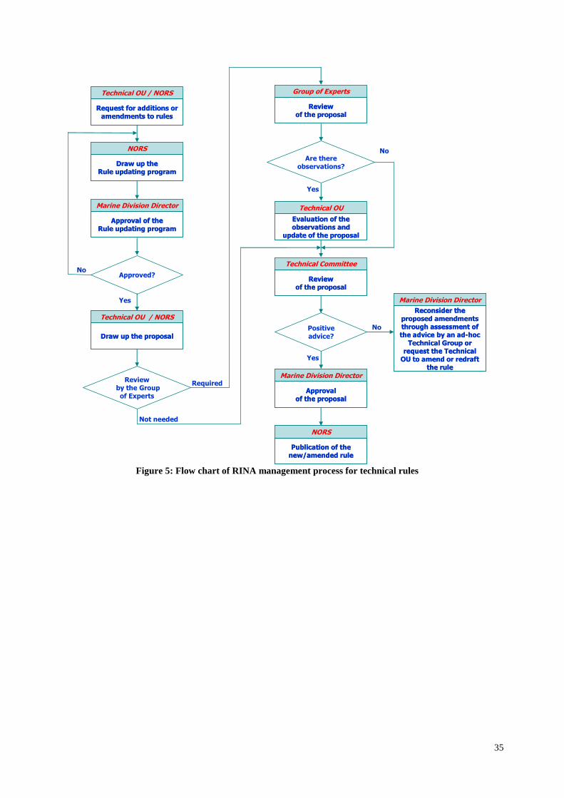
35
Technical OU / NORS
Request for additions or amendments to rules
Technical OU / NORS
Request for additions or amendments to rules
NORS
Draw up the Rule updating program
NORS
Draw up the Rule updating program
Approved?No
Yes
Technical OU / NORS
Draw up the proposal
Technical OU / NORS
Draw up the proposal
Reviewby the Group of Experts
Not needed
Required
Are there observations?
Technical OU
Evaluation of the observations and
update of the proposal
Technical OU
Evaluation of the observations and
update of the proposal
Yes
No
Marine Division Director
Approval of the Rule updating program
Marine Division Director
Approval of the Rule updating program
Group of Experts
Review of the proposal
Group of Experts
Review of the proposal
Technical Committee
Review of the proposal
Technical Committee
Review of the proposal
Positive advice?
No
Yes
Marine Division Director
Approval of the proposal
Marine Division Director
Approval of the proposal
NORS
Publication of the new/amended rule
NORS
Publication of the new/amended rule
Marine Division Director
Reconsider the proposed amendments through assessment of the advice by an ad-hoc
Technical Group or request the Technical
OU to amend or redraft the rule
Marine Division Director
Reconsider the proposed amendments through assessment of the advice by an ad-hoc
Technical Group or request the Technical
OU to amend or redraft the rule
Figure 5: Flow chart of RINA management process for technical rules
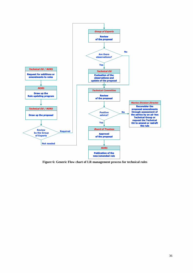
36
Figure 6: Generic Flow chart of LR management process for technical rules
Technical OU / NORS
Draw up the proposal
Technical OU / NORS
Draw up the proposal
Technical OU / NORS
Request for additions or amendments to rules
Technical OU / NORS
Request for additions or amendments to rules
NORS
Draw up the Rule updating program
NORS
Draw up the Rule updating program
Review by the Group
of Experts
Not needed
Required
Are there observations?
Technical OU
Evaluation of the observations and
update of the proposal
Technical OU
Evaluation of the observations and
update of the proposal
Yes
No
Group of Experts
Review of the proposal
Group of Experts
Review of the proposal
Technical Committee
Review of the proposal
Technical Committee
Review of the proposal
Positive advice?
No
Yes
Marine Division Director
Approval of the proposal
Board of Trustees
Approval of the proposal
NORS
Publication of the new/amended rule
NORS
Publication of the new/amended rule
Marine Division Director Reconsider the
proposed amendments through assessment of the advice by an ad - hoc
Technical Group or request the Technical
OU to amend or redraft the rule
Marine Division Director Reconsider the
proposed amendments through assessment of the advice by an ad - hoc
Technical Group or request the Technical
OU to amend or redraft the rule

Deliverable D2 MINOAS-WP1-D1.2 - 37 -3737
37
APPENDIX A - Comparison of the applicable regulations in the UK Offshore Industry
Legal Requirements for
Integrity Management
Demonstrated by Acts of
Parliament
Regulations and ACoP's
HSWA PUWER SCR
(2005)
DCR
(1996)
PFEER PSR PSSR LOLER RIDDOR
Provision and maintenance of
plant and systems of work that
are, so far as is reasonably
practicable, safe and without
risks to health
Operator/duty holder to
ensure equipment is
suitable for its purpose
and safe to operate
S2(2)(a) General
Duties
Reg 4 (1)
Suitability of
Work Equipment
Reg 13
modifications,
ACoP
Equipment to be maintained in
an efficient state, in efficient
working order, and in good
repair
Operator/duty holder to
maintain equipment in
good repair
Reg 5 (1) Reg 12 ACoP
Equipment exposed to
conditions causing
deterioration which is liable to
result in dangerous situations
is inspected at suitable
intervals
Inspection plan/ WSE Reg 6 (2)(a)
Identify safety critical elements
(SCE)
SCE listing Reg.6 &
19(1)
Reg. 26 (2)
Prepare performance standard
for each SCE
SCE performance
standards
Reg. 6

Deliverable D2 MINOAS-WP1-D1.2 - 38 -3838
38
Confirm, by appropriate
audit/examination/testing by
an independent body, that all
SCEs are suitable for their
intended purpose and remain
in good repair and condition
Independent verification
of SCE standards and
condition
y
Ensure that suitable
arrangements are in place for
maintaining the integrity of
the installation, including
suitable arrangements for:
(a) periodic assessment of its
integrity; and
(b) the carrying out of
remedial work in the event of
damage or deterioration which
may prejudice its integrity.
Inspection plan/ WSE Reg 8
Development of a Written
Scheme of Examination (PSSR
reg 8 specifies requirements
for WSE content)
WSE y y Regs 2, 8,
ACoP
Appoint competent person Competent person/body y Reg 2, ACoP
Thorough examination and
inspection at set intervals or to
plan
Examine and inspect Reg 2, 9
ACoP
Reg 9,
ACoP 349
Report defects (within 28 days
if PSSR)
Reporting Reg 9 ACoP Reg 10
reports,
ACoP 348
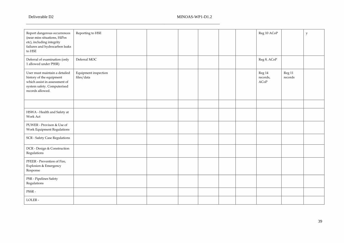
Deliverable D2 MINOAS-WP1-D1.2 - 39 -3939
39
Report dangerous occurrences
(near miss situations, HiPos
etc), including integrity
failures and hydrocarbon leaks
to HSE
Reporting to HSE Reg 10 ACoP y
Deferral of examination (only
1 allowed under PSSR)
Deferral MOC Reg 8, ACoP
User must maintain a detailed
history of the equipment
which assist in assessment of
system safety. Computerised
records allowed.
Equipment inspection
files/data
Reg 14
records,
ACoP
Reg 11
records
HSWA - Health and Safety at
Work Act
PUWER - Provison & Use of
Work Equipment Regulations
SCR - Safety Case Regulations
DCR - Design & Construction
Regulations
PFEER - Prevention of Fire,
Explosion & Emergency
Response
PSR - Pipelines Safety
Regulations
PSSR -
LOLER -
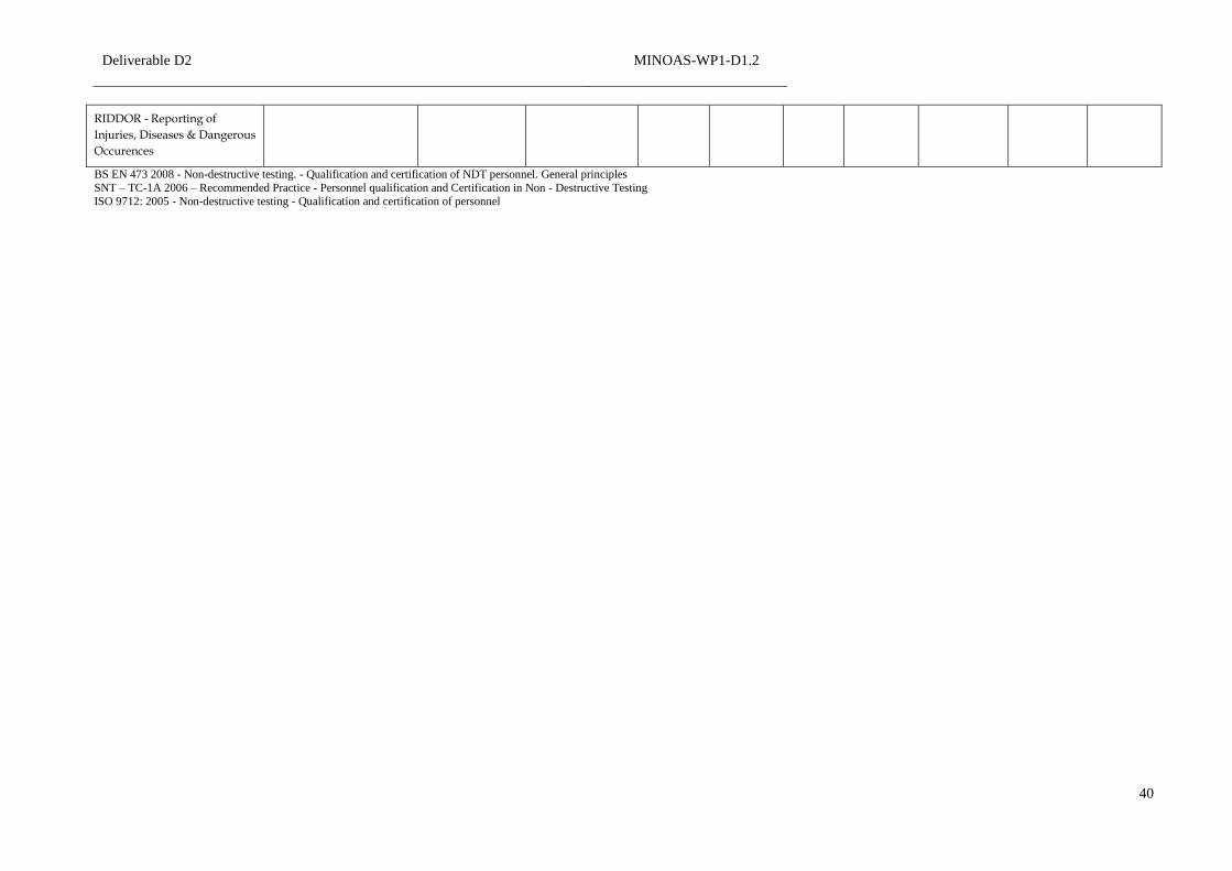
Deliverable D2 MINOAS-WP1-D1.2 - 40 -4040
40
RIDDOR - Reporting of
Injuries, Diseases & Dangerous
Occurences
BS EN 473 2008 - Non-destructive testing. - Qualification and certification of NDT personnel. General principles
SNT – TC-1A 2006 – Recommended Practice - Personnel qualification and Certification in Non - Destructive Testing
ISO 9712: 2005 - Non-destructive testing - Qualification and certification of personnel