Small, Light, High Speed & Torque 5-Phase Stepper Motor DriverMD 5 H F 14 No mark Zero point...
21
C-4 MD5 Series -|Transparent setting guide|- Small, Light, High Speed & Torque 5-Phase Stepper Motor Driver ● Bipolar constant pentagon drive method ● Includes auto current down and self-diagnosis function ● Low speed rotation and high accuracy controlling with microstep-driving (MD5-HD14, MD5-HF14, MD5-HF14-AO, MD5-HF28) [Max. resolution 250 division: In case of 5-phase stepper motor of which basic step angle is 0.72°, it enables to control up to 0.00288° per pulse and it requires 125,000 pulses per rotation.] ● Photocoupler input insulation method to minimize the effects from external noise Ordering Information Specifications Features Item Motor phase Step type (resolution) Power supply RUN current Output MD 14 5 H F No mark Zero point excitation output ※1 AO Alarm output 14 1.4A/Phase 28 2.8A/Phase D 20-35VDC F 100-220VAC H Micro step (250-division) N Normal Step 5 5-phase MD Motor Driver ※1: Except MD5-ND14 ※KR-55MC can be replaced with MD5-HD14. ※KR-5MC can be replaced with MD5-ND14. ※MD5-MF14 can be replaced with MD5-HF14. ※KR-505G can be replaced with MD5-HF28. MD5-HD14 MD5-ND14 MD5-HF14-AO MD5-HF14 MD5-HF28 Model MD5-HD14 MD5-HF14 MD5-HF14-AO MD5-HF28 MD5-ND14 Power supply 20-35VDCᜡ ※1 100-220VACᜠ 50/60Hz 20-35VDCᜡ ※1 Allowable voltage range 90 to 110% of the rated voltage Max. current consumption ※2 3A 5A 3A RUN current ※3 0.4-1.4A/Phase 1.0-2.8A/Phase 0.5-1.5A/Phase STOP current 27 to 90% of RUN current (set by STOP current switch) 25 to 75% of RUN current (set by STOP current volume) Drive method Bipolar constant current pentagon drive Basic step angle 0.72˚/step Resolution 1, 2, 4, 5, 8, 10, 16, 20, 25, 40, 50, 80, 100, 125, 200, 250-division (0.72 to 0.00288 /Step) 1, 2-division (0.72 , 0.36 /step) Input pulse characteristic Pulse width Min. 1㎲ (CW, CCW), Min. 1ms (HOLD OFF) Min. 10㎲ (CW, CCW), Min. 1ms (HOLD OFF) Duty rate 50% (CW, CCW) Rising/Falling time Below 130ns (CW, CCW) Pulse input voltage [H]: 4-8VDCᜡ, [L]: 0-0.5VDC Pulse input current 7.5-14mA (CW, CCW), 10-16mA (HOLD OFF, DIVISION SELECTION, ZERO OUT) ※4 Max. input pulse frequency ※ 5 Max. 500kHz (CW, CCW) Max. 50kHz (CW, CCW) Input resistance 270Ω (CW, CCW), 390Ω (HOLD OFF, DIVISION SELECTION), 10Ω (ZERO OUT) 270Ω (CW, CCW), 390Ω (HOLD OFF), 10Ω (ALARM) 270Ω (CW, CCW), 390Ω (HOLD OFF, DIVISION SELECTION), 10Ω (ZERO OUT) 390Ω (CW, CCW, HOLD OFF) Insulation resistance Over 100MΩ (at 500VDC megger, between all terminals and case) Dielectric strength 1000VAC 50/60Hz for 1min (between all terminals and case) Noise immunity ±500V the square wave noise (pulse width: 1μs) by the noise simulator ±2kV the square wave noise (pulse width: 1μs) by the noise simulator ±500V the square wave noise (pulse width: 1μs) by the noise simulator Vibration Mechanical 1.5mm amplitude at frequency 5 to 60Hz (for 1 min) in each X, Y, Z direction for 2 hours Malfunction 1.5mm amplitude at frequency 5 to 60Hz (for 1 min) in each X, Y, Z direction for 10 min Environ- ment Ambient temp. 0 to 40℃, storage: -10 to 60℃ 0 to 50℃, storage: -10 to 60℃ 0 to 40℃, storage: -10 to 60℃ Ambient humi. 35 to 85%RH, storage: 35 to 85%RH Approval ᜢ ᜢ ᜧ ᜢ ᜧ ᜢ ᜧ ᜢ Weight ※6 Approx. 327.5g (approx. 220g) Approx. 840g (approx. 680g) Approx. 820g (approx. 660g) Approx. 1.35kg (approx. 1.2kg) Approx. 183g (approx. 130g) ※1: When using over 30VDC power supply, torque characteristics are improved but the driver temperature raise. The unit should be installed at the well ventilation environment. ※2: Based on ambient temperature 25℃, ambient humidity 55%RH. ※3: RUN current varies depending on the input RUN frequency and max. RUN current at the moment varies also varies depending on the load. ※4: In case of MD5-HF14-AO, MD5-ND14, there are no DIVISION SELECTION, ZERO OUT function. ※5: Max. input pulse frequency is max. frequency to be input and is not same as max. pull-out frequency or max. slewing frequency. ※6: The weight includes packaging. The weight in parenthesis is for unit only. ※Environment resistance is rated at no freezing or condensation. (only for MD5-HF14(-AO), MD5-HF28 model) Please read “Safety Considerations” in the instruction manual before using.
Transcript of Small, Light, High Speed & Torque 5-Phase Stepper Motor DriverMD 5 H F 14 No mark Zero point...

C-4
MD5 Series-|Transparent setting guide|-
Small, Light, High Speed & Torque 5-Phase Stepper Motor Driver Bipolar constant pentagon drive method Includes auto current down and self-diagnosis function Low speed rotation and high accuracy controlling with
microstep-driving (MD5-HD14, MD5-HF14, MD5-HF14-AO, MD5-HF28) [Max. resolution 250 division: In case of 5-phase stepper motor of which basic step angle is 0.72°, it enables to control up to 0.00288° per pulse and it requires 125,000 pulses per rotation.]
Photocoupler input insulation method to minimize the effects from external noise
Ordering Information
Specifications
Features
Item
Motor phase
Step type (resolution)
Power supply
RUN current
Output
MD 145 H FNo mark Zero point excitation output※1
AO Alarm output
14 1.4A/Phase28 2.8A/Phase
D 20-35VDCF 100-220VAC
H Micro step (250-division)N Normal Step
5 5-phase
MD Motor Driver※1: Except MD5-ND14
※KR-55MC can be replaced with MD5-HD14.※KR-5MC can be replaced with MD5-ND14.※MD5-MF14 can be replaced with MD5-HF14.※KR-505G can be replaced with MD5-HF28.
MD5-HD14MD5-ND14MD5-HF14-AO
MD5-HF14MD5-HF28
Model MD5-HD14 MD5-HF14 MD5-HF14-AO MD5-HF28 MD5-ND14 Power supply 20-35VDCᜡ
※1 100-220VACᜠ 50/60Hz 20-35VDCᜡ※1
Allowable voltage range 90 to 110% of the rated voltageMax. current consumption※2 3A 5A 3ARUN current※3 0.4-1.4A/Phase 1.0-2.8A/Phase 0.5-1.5A/Phase
STOP current 27 to 90% of RUN current (set by STOP current switch)25 to 75% of RUN current (set by STOP current volume)
Drive method Bipolar constant current pentagon drive Basic step angle 0.72˚/stepResolution 1, 2, 4, 5, 8, 10, 16, 20, 25, 40, 50, 80, 100, 125, 200, 250-division (0.72 to 0.00288 /Step) 1, 2-division (0.72, 0.36/step)
Inpu
t pul
sech
arac
teris
tic
Pulse width Min. 1 (CW, CCW), Min. 1ms (HOLD OFF) Min. 10 (CW, CCW), Min. 1ms (HOLD OFF)
Duty rate 50% (CW, CCW)Rising/Falling time Below 130ns (CW, CCW)Pulse input voltage [H]: 4-8VDCᜡ, [L]: 0-0.5VDC Pulse input current 7.5-14mA (CW, CCW), 10-16mA (HOLD OFF, DIVISION SELECTION, ZERO OUT)※4
Max. input pulse frequency※5 Max. 500kHz (CW, CCW) Max. 50kHz (CW, CCW)
Input resistance270Ω (CW, CCW), 390Ω (HOLD OFF, DIVISION SELECTION), 10Ω (ZERO OUT)
270Ω (CW, CCW), 390Ω (HOLD OFF), 10Ω (ALARM)
270Ω (CW, CCW), 390Ω (HOLD OFF,DIVISION SELECTION),10Ω (ZERO OUT)
390Ω (CW, CCW, HOLD OFF)
Insulation resistance Over 100MΩ (at 500VDC megger, between all terminals and case)Dielectric strength 1000VAC 50/60Hz for 1min (between all terminals and case)
Noise immunity±500V the square wave noise (pulse width: 1μs) by the noise simulator
±2kV the square wave noise (pulse width: 1μs) by the noise simulator±500V the square wave noise (pulse width: 1μs) by the noise simulator
Vibration Mechanical 1.5mm amplitude at frequency 5 to 60Hz (for 1 min) in each X, Y, Z direction for 2 hoursMalfunction 1.5mm amplitude at frequency 5 to 60Hz (for 1 min) in each X, Y, Z direction for 10 min
Environ-ment
Ambient temp. 0 to 40, storage: -10 to 60 0 to 50, storage: -10 to 60 0 to 40,
storage: -10 to 60Ambient humi. 35 to 85%RH, storage: 35 to 85%RH
Approval ᜢ ᜢ ᜧ ᜢ ᜧ ᜢ ᜧ ᜢ
Weight※6 Approx. 327.5g (approx. 220g)
Approx. 840g (approx. 680g)
Approx. 820g (approx. 660g)
Approx. 1.35kg (approx. 1.2kg)
Approx. 183g (approx. 130g)
※1: When using over 30VDC power supply, torque characteristics are improved but the driver temperature raise. The unit should be installed at the well ventilation environment.
※2: Based on ambient temperature 25, ambient humidity 55%RH. ※3: RUN current varies depending on the input RUN frequency and max. RUN current at the moment varies also varies depending on the load.※4: In case of MD5-HF14-AO, MD5-ND14, there are no DIVISION SELECTION, ZERO OUT function.※5: Max. input pulse frequency is max. frequency to be input and is not same as max. pull-out frequency or max. slewing frequency. ※6: The weight includes packaging. The weight in parenthesis is for unit only. ※Environment resistance is rated at no freezing or condensation.
(only for MD5-HF14(-AO), MD5-HF28 model)
Please read “Safety Considerations” in the instruction manual before using.

C-5
SENSORS
FIELD INSTRUMENTS
CONTROLLERS
MOTION DEVICES
SOFTWARE
(A)Closed Loop Stepper System
(B)Stepper Motors
(C)Stepper MotorDrivers
(D)Motion Controllers
-|Transparent setting guide|-
Function selection DIP switch
TEST Self diagnosis function is for motor and driver test. This function makes the motor rotate with 30rpm in full step. Rotation speed varies with resolution settings. Rotation speed = 30rpm/resolution In 1-pulse input method, it rotates to CCW, and in 2-pulse input method, it rotates to CW. ※ Be sure that the TEST switch is OFF before supplying the power.
If the TEST switch is ON, the motor operates immediately and it may be dangerous. 1/2 CLK
1/2 CLK switch is to select pulse input method. 1-pulse input method: CW → operating rotation signal input, CCW → rotation direction signal input ([H]: CW, [L]: CCW) 2-pulse input method: CW → CW rotation signal input, CCW → CCW rotation signal input. C/D (auto current down)
This function is to reduce the current provided for motor automatically for preventing severe motor's heat when motor stops. If motor RUN pulse is not applied, the current provided for motor reduces as the set STOP current. ※ Be sure that when motor RUN current is reduced, the stop torque of motor also reduced. ※ Set the STOP current by the STOP current switch.
Setting RUN current
5-Phase Micro Stepper Motor Driver [MD5-HD14]Resolution switch RUN current switch
STOP current switch
Functionselection
DIP switch
Power indicator Inputterminal Zero
outputPowerterminal
Motorconnection
terminal
Switch No. 0 1 2 3 4 5 6 7 8 9 A B C D E F
Current (A/Phase) 0.4 0.5 0.57 0.63 0.71 0.77 0.84 0.9 0.96 1.02 1.09 1.15 1.22 1.27 1.33 1.4
Switch No. 0 1 2 3 4 5 6 7 8 9 A B C D E F
% 27 31 36 40 45 50 54 58 62 66 70 74 78 82 86 90
Unit Description
No. Name FunctionSwitch positionON OFF (default)
1 TEST Self diagnosis function 30rpm rotation Not use2 1/2 CLK Pulse input method 1-pulse input method 2-pulse input method3 C/D Auto current down Not use Use
Setting RUN current is for the current provided for motor when the motor runs.※When RUN current is increased, RUN torque of the motor is also increased. ※When RUN current is set too high, the heat is severe.※Set RUN current within the range of motor's rated current according to its load. ※Change RUN current only when the motor stops.
Setting STOP current is for the current provided for motor when the motor stops for preventing severe motor's heat. This setting is applied when using C/D (current down) function. Setting value of STOP current is percentage (%) ratio of the set RUN current.
E.g.) Set RUN current as 1.4A and STOP current as 40%. STOP current is set as 1.4A×0.4=0.56A
※When STOP current is decreased, STOP torque of the motor is also decreased. ※When STOP current is set too low, the heat is lower.※Change STOP current only when the motor stops.
Setting STOP current
Functions※Refer to ' Specifications'.
5-Phase Stepper Motor Driver (1.4A/Phase, DC Power)

C-6
MD5 Series-|Transparent setting guide|-
Zero point excitation output signal (ZERO OUT)CW Pulse
CCW Pulse
ZERO OUT
ONOFFON
OFF
ONOFF
0 0 01 1 12 23 4 5 6 7 8 9
Switch No. 0 1 2 3 4 5 6 7 8 9 A B C D E FResolution 1 2 4 5 8 10 16 20 25 40 50 80 100 125 200 250Step angle 0.72° 0.36° 0.18° 0.144° 0.09° 0.072° 0.045° 0.036° 0.0288° 0.018° 0.0144° 0.009° 0.0072° 0.00576° 0.0036° 0.00288°
This output indicates the initial step of excitation order of stepper motor and rotation position of motor axis. This signal outputs every 7.2° of rotation of the motor axis regardless of resolution. (50 outputs per 1 rotation of the motor.) E.g.) Full step: outputs one time by 10 pulses input, 20-division: outputs one time by 200 pulses input.
This signal is for rotating motor's axis using external force or used for manual positioning. When hold off signal maintains over 1ms as [H], motor excitation is released. When hold off signal maintains over 1ms as [L], motor excitation is in a normal status.※Must stop the motor for using this function. ※Refer to ' I/O Circuit and Connections'.
HOLD OFF function
Setting Microstep (microstep: resolution)
Setting Resolution (same as MS1, MS2) The MS1, MS2 switches is for resolution setting. Select MS2 or MS2 by DIVISION SELECTION signal ([L]: MS1, [H]: MS2) Select the step angle (motor rotation angle per 1 pulse). The set step angle is dividing basic step angle (0.72°) of 5-phase stepper motor by setting value. The calculation formula of divided step angle is as below.
When using geared type motor, the angle is step angle divided by gear ratio. Step angle / gear ratio = Step angle applied gear E.g) 0.72° / 10 (1:10) = 0.072°
※Must stop the motor before changing the resolution.
Set step angle = Basic step angle (0.72°)
Resolution
※CW 2-pulse input method (CW rotation signal input)1-pulse input method (operating rotation signal input)※CCW 2-pulse input method (CCW rotation signal input)1-pulse input method (rotation direction signal input)→ [H]: CW, [L]: CCW ※HOLD OFFControl signal for motor excitation OFF→ [H]: Motor excitation OFF※DIVISION SELECTIONDivision selection signal→ [L]: Operated by MS1 setting resolution [H]: Operated by MS2 setting resolution※ZERO OUTZero point excitation output signal → Zero point status ON※If the power for driving pulse from external is over
than +5VDC, please connect resistor at the outside.(input power max. 24VDC, input current 10-20mA)
I/O Circuit and Connections
Motor
270Ω
270Ω CW
+5VDC
CCW
HOLD OFF
DIVISION SELECTION
390Ω
390Ω
[Signal]
[Motor]
[Power]
10Ω
GND
ZERO OUT
BLUE
RED
ORANGE
GREEN
5
4
3
2
1
1
2
3
4
5
6
7
8
9
10
1
2
BLACK※This connection cable color is only for Autonics motors.
It may different cable color when using other motors.
Power 20-35VDC
+
-
Pentagon connection
Standard connection
Blue Gray+Red
Red Yellow+Black
Orange Orange+White
Green Brown+Green
Black Blue+Purple

C-7
SENSORS
FIELD INSTRUMENTS
CONTROLLERS
MOTION DEVICES
SOFTWARE
(A)Closed Loop Stepper System
(B)Stepper Motors
(C)Stepper MotorDrivers
(D)Motion Controllers
-|Transparent setting guide|-
Connections
Dimensions(unit: mm)
※ In case of standard connection, refer to 'Stepper Motors' section.
Division selectionsignalZero pointexcitation
output signalCW
+C
W-
CC
W+
CC
W-
HOLD
OFF
+HO
LD O
FF-
UserController
+
+
+
-
-
-Black
GreenOrange
RedBlue
POWER20-35VDC
Motor
4.5
2039.5
100
8676.5
7438
4.5
94 100
105
5-Phase Stepper Motor Driver (1.4A/Phase, DC Power)

C-8
MD5 Series-|Transparent setting guide|-
5-Phase Micro Stepper Motor Driver [MD5-HF14]
Function selection DIP switch
※Refer to ' Specifications'.
Resolution switchRUN current switch
STOP current switchFunction selection DIP switch
Power indicator Inputterminal
Alarm indicator (red)
Powerterminal
Motorconnection
terminal
Unit Description
No. Name Function Switch positionON OFF (default)
1 TEST Self diagnosis function 30rpm rotation Not use2 2/1 CLK Pulse input method 1-pulse input method 2-pulse input method3 C/D Auto current down Not use Use
TEST Self diagnosis function is for motor and driver test. This function makes the motor rotate with 30rpm in full step. Rotation speed varies with resolution settings. Rotation speed = 30rpm/resolution In 1-pulse input method, it rotates to CCW, and in 2-pulse input method, it rotates to CW. ※ Be sure that the TEST switch is OFF before supplying the power.
If the TEST switch is ON, the motor operates immediately and it may be dangerous. 2/1 CLK
2/1 CLK switch is to select pulse input method. 1-pulse input method: CW → operating rotation signal input, CCW → rotation direction signal input ([H]: CW, [L]: CCW) 2-pulse input method: CW → CW rotation signal input, CCW → CCW rotation signal input.
C/D (auto current down) This function is to reduce the current provided for motor automatically for preventing severe motor's heat when motor stops. If motor RUN pulse is not applied, the current provided for motor reduces as the set STOP current. ※Be sure that when motor RUN current is reduced, the stop torque of motor also reduced. ※ Set the STOP current by the STOP current switch.
Setting RUN current Switch No. 0 1 2 3 4 5 6 7 8 9 A B C D E F
Current (A/Phase) 0.4 0.5 0.57 0.63 0.71 0.77 0.84 0.9 0.96 1.02 1.09 1.15 1.22 1.27 1.33 1.4
Switch No. 0 1 2 3 4 5 6 7 8 9 A B C D E F
% 27 31 36 40 45 50 54 58 62 66 70 74 78 82 86 90
Setting RUN current is for the current provided for motor when the motor runs.※When RUN current is increased, RUN torque of the motor is also increased. ※When RUN current is set too high, the heat is severe.※Set RUN current within the range of motor's rated current according to its load. ※Change RUN current only when the motor stops.
Setting STOP current is for the current provided for motor when the motor stops for preventing severe motor's heat. This setting is applied when using C/D (current down) function. Setting value of STOP current is percentage (%) ratio of the set RUN current. E.g.) Set RUN current as 1.4A and STOP current as 40%.
STOP current is set as 1.4A×0.4=0.56A※When STOP current is decreased, STOP torque of the motor is also decreased. ※When STOP current is set too low, the heat is lower.※Change STOP current only when the motor stops.
Setting STOP current
Functions

C-9
SENSORS
FIELD INSTRUMENTS
CONTROLLERS
MOTION DEVICES
SOFTWARE
(A)Closed Loop Stepper System
(B)Stepper Motors
(C)Stepper MotorDrivers
(D)Motion Controllers
-|Transparent setting guide|-
Zero point excitation output signal (ZERO OUT)CW Pulse
CCW Pulse
ZERO OUT
ONOFFON
OFF
ONOFF
0 0 01 1 12 23 4 5 6 7 8 9 This output indicates the initial step of excitation order of stepper motor and rotation position of motor axis . This signal outputs every 7.2° of rotation of the motor axis regardless of resolution. (50 outputs per 1 rotation of the motor.) E.g.) Full step: outputs one time by 10 pulses input, 20-division: outputs one time by 200 pulses input.
This signal is for rotating motor's axis using external force or used for manual positioning. When hold off signal maintains over 1ms as [H], motor excitation is released. When hold off signal maintains over 1ms as [L], motor excitation is in a normal status.※Must stop the motor for using this function. ※Refer to ' I/O Circuit and Connections'.
HOLD OFF function
Alarm indication
Switch No. 0 1 2 3 4 5 6 7 8 9 A B C D E FResolution 1 2 4 5 8 10 16 20 25 40 50 80 100 125 200 250Step angle 0.72° 0.36° 0.18° 0.144° 0.09° 0.072° 0.045° 0.036° 0.0288° 0.018° 0.0144° 0.009° 0.0072° 0.00576° 0.0036° 0.00288°
Setting Microstep (microstep: resolution)
Setting Resolution (same as MS1, MS2) The MS1, MS2 switches is for resolution setting. Select MS2 or MS2 by DIVISION SELECTION signal ([L]: MS1, [H]: MS2) Select the step angle (motor rotation angle per 1 pulse). The set step angle is dividing basic step angle (0.72°) of 5-phase stepper motor by setting value. The calculation formula of divided step angle is as follow.
When using geared type motor, the angle is step angle divided by gear ratio. Step angle / gear ratio = Step angle applied gear E.g) 0.72° / 10 (1:10) = 0.072°
※Must stop the motor before changing the resolution.
Set step angle = Basic step angle (0.72°)
Resolution
Overheat: When the temperature of driver base is over 80, the alarm indicator (red) turns ON and motor stops with holding the excision. Overcurrent: When overcurrent occurs due to motor damage by burn, driver damage, or error, the alarm indicator (red) turns ON and the
motor becomes HOLD OFF. ※Turn OFF the power and remove the causes of alarm. Re-supply the power and the alarm indicator turns OFF and the driver is normal
operation.
I/O Circuit and Connections※CW 2-pulse input method (CW rotation signal input)1-pulse input method (operating rotation signal input)※CCW 2-pulse input method (CCW rotation signal input)1-pulse input method (rotation direction signal input)→ [H]: CW, [L]: CCW ※HOLD OFFControl signal for motor excitation OFF→ [H]: Motor excitation OFF※DIVISION SELECTIONDivision selection signal→ [L]: Operated by switch MS1 [H]: Operated by switch MS2※ZERO OUTZero point excitation output signal → Zero point status ON
※If the power for driving pulse from external is over than +5VDC, please connect resistor at the outside.(input power max. 24VDC, input current 10-20mA)
[Signal]
[Motor]
[Power]
※This connection cable color is only for Autonics motors. It may different cable color when using other motors.
Power
BLUE
RED
ORANGE
GREEN
BLACK
L
N
100-220VAC50/60Hz
GNDG
AC
AC
5
4
3
2
1
1
2
3
4
5
6
7
8
9
10
270Ω
270Ω
390Ω
390Ω
10Ω
CW
CCW
HOLDOFF
+5VDC
+5VDC
ZERO OUT
DIVISION SELECTION
2kΩ
Motor
Pentagon connection
Standard connection
Blue Gray+Red
Red Yellow+Black
Orange Orange+White
Green Brown+Green
Black Blue+Purple
5-Phase Stepper Motor Driver (1.4A/Phase, AC Power)

C-10
MD5 Series-|Transparent setting guide|-
Connections
Dimensions(unit: mm)
※In case of standard connection, refer to 'Stepper Motors' section.
Division selectionsignal
F.G.
Zero point excitationoutput signal
+-
+-
BlackGreenOrangeRedBlue
Motor 100-220VAC 50/60HzC
W+
CW
-C
CW
+C
CW
-HO
LD O
FF+
HOLD
OFF
-
UserController
5
4240
156
20 108
122133.5
5.4
4-M4 Tap Depth: 8
7
120
170

C-11
SENSORS
FIELD INSTRUMENTS
CONTROLLERS
MOTION DEVICES
SOFTWARE
(A)Closed Loop Stepper System
(B)Stepper Motors
(C)Stepper MotorDrivers
(D)Motion Controllers
-|Transparent setting guide|-
5-Phase Micro Stepper Motor Driver [MD5-HF14-AO]
Function selection DIP switch
Resolution switch
Function selection DIP switch
Power indicatorAlarm indicator (red)
Powerterminal
Motorconnection
terminal
RUN current switchSTOP current switch
Input/Outputterminal
※Refer to ' Specifications'.
Unit Description
TEST Self diagnosis function is for motor and driver test. This function makes the motor rotate with 30rpm in full step. Rotation speed varies with resolution settings. Rotation speed = 30rpm/resolution In 1-pulse input method, it rotates to CCW, and in 2-pulse input method, it rotates to CW. ※ Be sure that the TEST switch is OFF before supplying the power.
If the TEST switch is ON, the motor operates immediately and it may be dangerous. 2/1 CLK
2/1 CLK switch is to select pulse input method. 1-pulse input method: CW → operating rotation signal input, CCW → rotation direction signal input ([H]: CW, [L]: CCW) 2-pulse input method: CW → CW rotation signal input, CCW → CCW rotation signal input.
C/D (auto current down) This function is to reduce the current provided for motor automatically for preventing severe motor's heat when motor stops. If motor RUN pulse is not applied, the current provided for motor reduces as the set STOP current. ※ Be sure that when motor RUN current is reduced, the stop torque of motor also reduced. ※ Set the STOP current by the STOP current switch.
Setting RUN current Switch No. 0 1 2 3 4 5 6 7 8 9 A B C D E F
Current (A/Phase) 0.4 0.5 0.57 0.63 0.71 0.77 0.84 0.9 0.96 1.02 1.09 1.15 1.22 1.27 1.33 1.4
Switch No. 0 1 2 3 4 5 6 7 8 9 A B C D E F
% 27 31 36 40 45 50 54 58 62 66 70 74 78 82 86 90
Setting RUN current is for the current provided for motor when the motor runs.※When RUN current is increased, RUN torque of the motor is also increased. ※When RUN current is set too high, the heat is severe.※Set RUN current within the range of motor's rated current according to its load. ※Change RUN current only when the motor stops.
Setting STOP current is for the current provided for motor when the motor stops for preventing severe motor's heat. This setting is applied when using C/D (current down) function. Setting value of STOP current is percentage (%) ratio of the set RUN current.
E.g.) Set RUN current as 1.4A and STOP current as 40%. STOP current is set as 1.4A×0.4=0.56A
※When STOP current is decreased, STOP torque of the motor is also decreased. ※When STOP current is set too low, the heat is lower.※Change STOP current only when the motor stops.
Setting STOP current
No. Name FunctionSwitch positionON OFF (default)
1 TEST Self diagnosis function 30rpm rotation Not use2 2/1 CLK Pulse input method 1-pulse input method 2-pulse input method3 C/D Auto current down Not use Use
Functions
5-Phase Stepper Motor Driver (1.4A/Phase, AC Power, Alarm Output)

C-12
MD5 Series-|Transparent setting guide|-
This signal is for rotating motor's axis using external force or used for manual positioning. When hold off signal maintains over 1ms as [H], motor excitation is released. When hold off signal maintains over 1ms as [L], motor excitation is in a normal status.※Must stop the motor for using this function. ※Refer to ' I/O Circuit and Connections'.
HOLD OFF function
Switch No. 0 1 2 3 4 5 6 7 8 9 A B C D E FResolution 1 2 4 5 8 10 16 20 25 40 50 80 100 125 200 250Step angle 0.72° 0.36° 0.18° 0.144° 0.09° 0.072° 0.045° 0.036° 0.0288° 0.018° 0.0144° 0.009° 0.0072° 0.00576° 0.0036° 0.00288°
Setting Microstep (microstep: resolution)
Setting Resolution (MS1) The set step angle is dividing basic step angle (0.72°) of 5-phase stepper motor by setting value. The calculation formula of divided step angle is as below.
When using geared type motor, the angle is step angle divided by gear ratio. Step angle / gear ratio = Step angle applied gear E.g) 0.72° / 10 (1:10) = 0.072°
※Must stop the motor before changing the resolution.
Set step angle = Basic step angle (0.72°)
Resolution
※CW 2-pulse input method (CW rotation signal input)1-pulse input method (operating rotation signal input)
※CCW 2-pulse input method (CCW rotation signal input)1-pulse input method (rotation direction signal input)→ [H]: CW, [L]: CCW
※HOLD OFFControl signal for motor excitation OFF→ [H]: Motor excitation OFF
※When alarm occurs, the motor becomes HOLD OFF. Turn OFF the power and remove the causes to normal operation.
Over heat:
Over current:
※If the power for driving pulse from external is over than +5VDC, please connect resistor at the outside. (input power max. 24VDC, input current 10-24mA)
I/O Circuit and Connections
BLUE
RED
ORANGE
GREEN
BLACK
L
N100-220VAC
50/60Hz
GND
Motor
G
AC
AC
5
4
3
2
1
1
2
3
4
5
6
7
9
10
270Ω
270Ω
390Ω
10Ω
2kΩ
CW
CCW
HOLD OFF
5-24VDC
+5VDC
Alarm OUT -
Alarm OUT +8
Power
Pentagon connection
Standard connection
Blue Gray+Red
Red Yellow+Black
Orange Orange+White
Green Brown+Green
Black Blue+Purple
[Motor]
[Power]
[Signal]
※This connection cable color is only for Autonics motors. It may different cable color when using other motors.
Alarm indication/output Overheat: When the temperature of driver base is over 80, the alarm indicator (red) turns ON and motor stops and alarm output turns
ON with holding the excision. Overcurrent: When overcurrent occurs due to motor damage by burn, driver damage, or error, the alarm indicator (red) turns ON and
alarm output turns ON. The motor becomes HOLD OFF. ※Turn OFF the power and remove the causes of alarm. Re-supply the power and the alarm indicator turns OFF and alarm output turns OFF.
The driver is normal operation.

C-13
SENSORS
FIELD INSTRUMENTS
CONTROLLERS
MOTION DEVICES
SOFTWARE
(A)Closed Loop Stepper System
(B)Stepper Motors
(C)Stepper MotorDrivers
(D)Motion Controllers
-|Transparent setting guide|-
Dimensions
Connections
(unit: mm)
CW
+C
W-
CC
W+
CC
W-
HOLD
OFF
+HO
LD O
FF-
UserController
Alarm output +
-
BlackGreenOrangeRedBlue
MotorF.G.
100-220VAC 50/60Hz
5-24VDC
※In case of standard connection, refer to 'Stepper Motors' section.
20
42
5
40
156
108
122133.5
5.4
4-M4 Tap Depth: 8
7
120
170
5-Phase Stepper Motor Driver (1.4A/Phase, AC Power, Alarm Output)

C-14
MD5 Series-|Transparent setting guide|-
※KR-505G can be replaced with MD5-HF28. ※ Power supply 100-220VAC and socket type wire terminal blocks are
upgraded comparing to KR Series.
5-Phase Microstep Motor Driver [MD5-HF28]Resolution switch
RUN current switchSTOP current switch
Functionselection
DIP switch
Power indicatorAlarm indicator (red)
※Refer to ' Specifications'.
Unit Description
Function selection DIP switchNo. Name Function Switch position
ON OFF (default)1 TEST Self diagnosis function 30rpm rotation Not use2 2/1 CLK Pulse input method 1-pulse input method 2-pulse input method3 C/D Auto Current Down Not use Use
TEST Self diagnosis function is for motor and driver test. This function makes the motor rotate with 30rpm in full step. Rotation speed varies with resolution settings. Rotation speed = 30rpm/resolution In 1-pulse input method, it rotates to CCW, and in 2-pulse input method, it rotates to CW. ※ Be sure that the TEST switch is OFF before supplying the power.
If the TEST switch is ON, the motor operates immediately and it may be dangerous. 2/1 CLK
2/1 CLK switch is to select pulse input method. 1-pulse input method: CW → operating rotation signal input, CCW → rotation direction signal input ([H]: CW, [L]: CCW) 2-pulse input method: CW → CW rotation signal input, CCW → CCW rotation signal input. C/D (auto current down)
This function is to reduce the current provided for motor automatically for preventing severe motor's heat when motor stops. If motor RUN pulse is not applied, the current provided for motor reduces as the set STOP current. ※Be sure that when motor RUN current is reduced, the stop torque of motor also reduced. ※ Set the STOP current by the STOP current switch.
Setting RUN current Switch No. 0 1 2 3 4 5 6 7 8 9 A B C D E F
Current (A/Phase) 1.14 1.25 1.36 1.50 1.63 1.74 1.86 1.97 2.10 2.20 2.30 2.40 2.50 2.60 2.78 2.88
Switch No. 0 1 2 3 4 5 6 7 8 9 A B C D E F
% 27 31 36 40 45 50 54 58 62 66 70 74 78 82 86 90
Setting RUN current is for the current provided for motor when the motor runs.※When RUN current is increased, RUN torque of the motor is also increased. ※When RUN current is set too high, the heat is severe.※Set RUN current within the range of motor's rated current according to its load. ※Change RUN current only when the motor stops.
Setting STOP current is for the current provided for motor when the motor stops for preventing severe motor's heat. This setting is applied when using C/D (current down) function. Setting value of STOP current is percentage (%) ratio of the set RUN current. E.g.) Set RUN current as 2.5A and STOP current as 40%.
STOP current is set as 2.5A×0.4=1A※When STOP current is decreased, STOP torque of the motor is also decreased. ※When STOP current is set too low, the heat is lower.※Change STOP current only when the motor stops.
Setting STOP current
Functions
5-Phase Stepper Motor Driver (2.8A/Phase, AC Power)

C-15
SENSORS
FIELD INSTRUMENTS
CONTROLLERS
MOTION DEVICES
SOFTWARE
(A)Closed Loop Stepper System
(B)Stepper Motors
(C)Stepper MotorDrivers
(D)Motion Controllers
-|Transparent setting guide|-
Zero point excitation output signal (ZERO OUT)CW Pulse
CCW Pulse
ZERO OUT
ONOFFON
OFF
ONOFF
0 0 01 1 12 23 4 5 6 7 8 9
Switch No. 0 1 2 3 4 5 6 7 8 9 A B C D E FResolution 1 2 4 5 8 10 16 20 25 40 50 80 100 125 200 250Step angle 0.72° 0.36° 0.18° 0.144° 0.09° 0.072° 0.045° 0.036° 0.0288° 0.018° 0.0144° 0.009° 0.0072° 0.00576° 0.0036° 0.00288°
This output indicates the initial step of excitation order of stepper motor and rotation position of motor axis. This signal outputs every 7.2° of rotation of the motor axis regardless of resolution. (50 outputs per 1 rotation of the motor.) E.g.) Full step: outputs one time by 10 pulses input, 20-division: outputs one time by 200 pulses input.
This signal is for rotating motor's axis using external force or used for manual positioning. When hold off signal maintains over 1ms as [H], motor excitation is released. When hold off signal maintains over 1ms as [L], motor excitation is in a normal status.※Must stop the motor for using this function. ※Refer to ' I/O Circuit and Connections'.
HOLD OFF function
Setting Microstep (microstep: resolution)
Setting Resolution (same as MS1, MS2) The MS1, MS2 switches is for resolution setting. Select MS2 or MS2 by DIVISION SELECTION signal ([L]: MS1, [H]: MS2) Select the step angle (motor rotation angle per 1 pulse). The set step angle is dividing basic step angle (0.72°) of 5-phase stepper motor by setting value. The calculation formula of divided step angle is as follow.
When using geared type motor, the angle is step angle divided by gear ratio. Step angle / gear ratio = Step angle applied gear E.g) 0.72° / 10 (1:10) = 0.072°
※Must stop the motor before changing the resolution.
Set step angle = Basic step angle (0.72°)
Resolution
I/O Circuit and Connections
※This connection cable color is only for Autonics motors. It may different cable color when using other motors.
※CW 2-pulse input method (CW rotation signal input)1-pulse input method (operating rotation signal input)※CCW 2-pulse input method (CCW rotation signal input)1-pulse input method (rotation direction signal input)→ [H]: CW, [L]: CCW ※HOLD OFFControl signal for motor excitation OFF→ [H]: Motor excitation OFF※DIVISION SELECTIONDivision selection signal→ [L]: Operated by switch MS1 [H]: Operated by switch MS2※ZERO OUTZero point excitation output signal → Zero point status ON※If the power for driving pulse from external is over
than +5VDC, please connect resistor at the outside.
[Signal]
[Motor]
[Power]Power
BLUE
RED
ORANGE
GREEN
BLACK
L
N100-220VAC
50/60Hz
GNDG
AC
AC
5
4
32
1
1
2
3
4
5
6
7
8
9
10
270Ω
270Ω
390Ω
390Ω
10Ω
CW
CCW
HOLDOFF
+5VDC
+5VDC
ZERO OUT
DIVISION SELECTION
2kΩ
Motor
Pentagon connection
Standard connection
Blue Gray+Red
Red Yellow+Black
Orange Orange+White
Green Brown+Green
Black Blue+Purple
Alarm indication Overheat: When the temperature of driver base is over 80, the alarm indicator (red) turns ON and motor stops with holding the excision. Overcurrent: When overcurrent occurs due to motor damage by burn, driver damage, or error, the alarm indicator (red) turns ON and the
motor becomes HOLD OFF. ※Turn OFF the power and remove the causes of alarm. Re-supply the power and the alarm indicator turns OFF and the driver is normal
operation.
5-Phase Stepper Motor Driver (2.8A/Phase, AC Power)

C-16
MD5 Series-|Transparent setting guide|-
CW
+C
W-
CC
W+
CC
W-
HO
LD O
FF+
HO
LD O
FF-
UserController
+-
+-
BlackGreenOrangeRedBlue
Motor
※In case of standard connection, refer to 'Stepper Motors' section.
Division selectionsignal
Zero point excitationoutput signal
F.G.100-220VAC 50/60Hz
Connections
Dimensions (unit: mm)
54.1
R5 146
145.3127.5 10.5
5.516
3
200
211.
5
4-Ø
6
4-R0.5Ø5
185
5
4920

C-17
SENSORS
FIELD INSTRUMENTS
CONTROLLERS
MOTION DEVICES
SOFTWARE
(A)Closed Loop Stepper System
(B)Stepper Motors
(C)Stepper MotorDrivers
(D)Motion Controllers
-|Transparent setting guide|-
Function selection DIP switch
5-Phase Stepper Motor Driver [MD5-ND14]
Inputterminal
STOPcurrentvolume
RUN currentvolume
Functionselection DIP switch
Powerterminal
Motorconnection
terminal
※Refer to ' Specifications'.
Unit Description
※Changing pulse input method or resolution is available only when stepper motor stops. If changing the resolution during operation, the motor may be out of phase.
ON1 2
No. Nameplate FunctionSwitch positionON OFF (default)
1 1/2 CLK Pulse input method 1-pulse input method 2-pulse input method2 FULL↔HALF Select resolution 1-division (0.72°) 2-division (0.36°)
1/2 CLK 1/2 CLK switch is to select pulse input method. 1-pulse input method: CW → operating rotation signal input, CCW → rotation direction signal input ([H]: CW, [L]: CCW) 2-pulse input method: CW → CW rotation signal input, CCW → CCW rotation signal input.
FULL ↔ HALF FULL ↔ HALF switch is to set basic step angle for 5-phase stepper motor.※Change resolution only when the motor stops.
Setting RUN current RUN CURRENT
0.5A 1.5A
1.0A Setting RUN current is for the current provided for motor when the motor runs.※When RUN current is increased, RUN torque of the motor is also increased. ※When RUN current is set too high, the heat is severe.※Set RUN current within the range of motor's rated current according to its load. ※Change RUN current only when the motor stops.
Setting STOP current
25% 75%
STOP CURRENT Setting STOP current is for the current provided for motor when the motor stops. Setting value of STOP current is percentage (%) ratio of the set RUN current. E.g.) Set RUN current as 1.4A and STOP current as 40%.
STOP current is set as 1.4A×0.4=0.56A.※When STOP current is decreased, STOP torque of the motor is also decreased. ※When STOP current is set too low, the heat is lower.※Change STOP current only when the motor stops.
This signal is for rotating motor's axis using external force or used for manual positioning. When hold off signal maintains over 1ms as [H], motor excitation is released. When hold off signal maintains over 1ms as [L], motor excitation is in a normal status.※Must stop the motor for using this function. ※Refer to ' I/O Circuit and Connections'.
HOLD OFF function
Functions
5-Phase Stepper Motor Driver (1.5A/Phase, DC Power)

C-18
MD5 Series-|Transparent setting guide|-
I/O Circuit and Connections
※CW 2-pulse input method (CW rotation signal input)1-pulse input method (operating rotation signal input)
※CCW 2-pulse input method (CCW rotation signal input)1-pulse input method (rotation direction signal input)→ [H]: CW, [L]: CCW
※HOLD OFFControl signal for motor excitation OFF→ [H]: Motor excitation OFF
※If the power for driving pulse from external is over than +5VDC, please connect resistor at the outside. (input voltage max. 24VDC, input current 10-20mA)
※This connection cable color is only for Autonics motors. It may different cable color when using other motors.
※In case of standard connection, refer to 'Stepper Motors' section.
+5VDC
390Ω
390Ω
390Ω
CCW
CW
+5VDC Max. 30mA output
Power 20-35VDC
6
5
4
3
1
2
+
-
GND
HOLDOFF
[Motor]
[Power]
[Signal]
1
2
3
BLUE
RED
ORANGE
GREEN
BLACK
Motor
Pentagon connection
Standard connection
Blue Gray+Red
Red Yellow+Black
Orange Orange+White
Green Brown+Green
Black Blue+Purple5
4
3
1
2

C-19
SENSORS
FIELD INSTRUMENTS
CONTROLLERS
MOTION DEVICES
SOFTWARE
(A)Closed Loop Stepper System
(B)Stepper Motors
(C)Stepper MotorDrivers
(D)Motion Controllers
-|Transparent setting guide|-
2-pulse input method
1-pulse input method
CW[H][L]
CCW [H][L]
Rotation position CW CCW
CW CCW
[H][L]
[L][H]
CW
CCW
Rotation position
CW
(unit: mm)
80
87
93 55.5
87
4.5 20
32
4.5
22.5
45
Time Chart
Dimensions
※ Do not input CW, CCW signals at the same time in 2-pulse input method. It may not operate properly if another direction signal is inputted when one of CW or CCW is [H].
5-Phase Stepper Motor Driver (1.5A/Phase, DC Power)

C-20
MD5 Series-|Transparent setting guide|-
MD5-HD14-3X
MD5-HD14-2X
※ 1: Built-in zero point excitation output signal is optional.
FeaturesLow Noise, Low Vibration Multi-Axis 5-Phase Stepper Motor Driver Simultaneous operation of 2, 3-axis by single power supply
20-35VDC Small, light weight and advanced quality by custom IC and
surface mounted circuit Realizing low noise, low vibration rotation with microstep-driving Low speed rotation and high accuracy controlling
with microstep-driving Max. resolution 250 division: In case of 5-phase stepper motor
of which basic step angle is 0.72°, it enables to control up to 0.00288° per pulse
Includes auto current down and self-diagnosis function Photocoupler input insulation method to minimize the effects
from external noise
Ordering Information
SpecificationsItem
Motor phase
Step type (resolution)
Power supply
RUN current
Axis
MD 14 2X5 H D2X 2-axis3X 3-axis※ 1
14 1.4A/Phase
D 20-35VDC
H Micro step (250-division)
5 5-phase
MD Motor Driver
Model MD5-HD14-2X MD5-HD14-3XPower supply※1 20-35VDCᜡAllowable voltage fluctuation range 90 to 110% of the rated voltageMax. current consumption※2 5A 7ARUN current※3 0.4-1.4A/PhaseSTOP current 27 to 90% of RUN current (set by STOP current switch)Drive method Bipolar constant current pentagon driveBasic step angle 0.72 /StepResolution 1, 2, 4, 5, 8, 10, 16, 20, 25, 40, 50, 80, 100, 125, 200, 250-division (0.72 to 0.00288 /Step)
Inpu
t pul
se
char
acte
ristic
Pulse width Min. 1μs (CW, CCW), Min. 1ms (HOLD OFF)Duty rate 50% (CW, CCW)Rising/Falling time Below 130ns (CW, CCW)Pulse input voltage [H]: 4-8VDCᜡ, [L]: 0-0.5VDCPulse input current 7.5-14mA (CW, CCW), 10-16mA (HOLD OFF, ZERO OUT)Max. input pulse frequency※4 Max. 500kHz (CW, CCW)
Input resistance 270Ω (CW, CCW), 390Ω (HOLD OFF), 10Ω (ZERO OUT)Insulation resistance Over 100MΩ (at 500VDC megger, between all terminals and base)Dielectric strength 1,000VAC 50/60Hz for 1 min (between all terminals and base)Noise immunity ±500V the square wave noise (pulse width: 1μs) by the noise simulator
Vibration Mechanical 1.5mm amplitude at frequency 5 to 60Hz (for 1 min) in each X, Y, Z direction for 2 hoursMalfunction 1.5mm amplitude at frequency 5 to 60Hz (for 1 min) in each X, Y, Z direction for 10 min
Envi-ron-ment
Ambient temp. 0 to 40, storage: -10 to 60 Ambient humi. 35 to 85%RH, storage: 35 to 85%RH
Approval Weight※5 Approx. 446g (approx. 292g) Approx. 597g (approx. 411g)※1: When using over 30VDC power supply, torque characteristics are improved but the driver temperature raise. The unit should be installed at the well ventilation environment.※2: Based on ambient temperature 25, ambient humidity 55%RH.※3: RUN current varies depending on the input RUN frequency and max. RUN current at the moment varies also varies depending on the load. ※4: Max. input pulse frequency is max. frequency to be input and is not same as max. pull-out frequency or max. slewing frequency.※5: The weight includes packaging. The weight in parenthesis is for unit only.※Environment resistance is rated at no freezing or condensation.
Please read “Safety Considerations” in the instruction manual before using.
C-21
SENSORS
FIELD INSTRUMENTS
CONTROLLERS
MOTION DEVICES
SOFTWARE
(A)Closed Loop Stepper System
(B)Stepper Motors
(C)Stepper MotorDrivers
(D)Motion Controllers
-|Transparent setting guide|-
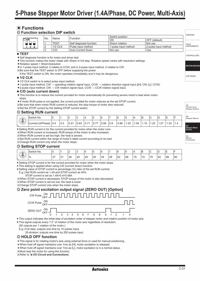
Functions Function selection DIP switch
No. Name Function Switch positionON OFF (default)
1 TEST Self diagnosis function 30rpm rotation Not use2 1/2 CLK Pulse input method 1-pulse input method 2-pulse input method3 C/D Auto Current Down Not use Use
TEST Self diagnosis function is for motor and driver test. This function makes the motor rotate with 30rpm in full step. Rotation speed varies with resolution settings. Rotation speed = 30rpm/resolution In 1-pulse input method, it rotates to CCW, and in 2-pulse input method, it rotates to CW. ※ Be sure that the TEST switch is OFF before supplying the power.
If the TEST switch is ON, the motor operates immediately and it may be dangerous. 1/2 CLK
1/2 CLK switch is to select pulse input method. 1-pulse input method: CW → operating rotation signal input, CCW → rotation direction signal input ([H]: CW, [L]: CCW) 2-pulse input method: CW → CW rotation signal input, CCW → CCW rotation signal input. C/D (auto current down)
This function is to reduce the current provided for motor automatically for preventing severe motor's heat when motor stops. If motor RUN pulse is not applied, the current provided for motor reduces as the set STOP current. ※ Be sure that when motor RUN current is reduced, the stop torque of motor also reduced. ※ Set the STOP current by the Setting STOP current switch.
Setting RUN current
Setting RUN current is for the current provided for motor when the motor runs.※When RUN current is increased, RUN torque of the motor is also increased. ※When RUN current is set too high, the heat is severe.※Set RUN current within the range of motor's rated current according to its load. ※Change RUN current only when the motor stops.
Setting STOP current is for the current provided for motor when the motor stops. This setting is applied when using C/D (current down) function. Setting value of STOP current is percentage (%) ratio of the set RUN current. E.g.) Set RUN current as 1.4A and STOP current as 40%.
STOP current is set as 1.4A×0.4=0.56A※When STOP current is decreased, STOP torque of the motor is also decreased. ※When STOP current is set too low, the heat is lower.※Change STOP current only when the motor stops.
Setting STOP current
Zero point excitation output signal (ZERO OUT) [Option]CW Pulse
CCW Pulse
ZERO OUT
ONOFFON
OFF
ONOFF
0 0 01 1 12 23 4 5 6 7 8 9 This output indicates the initial step of excitation order of stepper motor and rotation position of motor axis. This signal outputs every 7.2° of rotation of the motor axis regardless of resolution. (50 outputs per 1 rotation of the motor.) E.g.) Full step: outputs one time by 10 pulses input,
20-division: outputs one time by 200 pulses input.
Switch No. 0 1 2 3 4 5 6 7 8 9 A B C D E F
Current (A/Phase) 0.4 0.5 0.57 0.63 0.71 0.77 0.84 0.9 0.96 1.02 1.09 1.15 1.22 1.27 1.33 1.4
Switch No. 0 1 2 3 4 5 6 7 8 9 A B C D E F
% 27 31 36 40 45 50 54 58 62 66 70 74 78 82 86 90
This signal is for rotating motor's axis using external force or used for manual positioning. When hold off signal maintains over 1ms as [H], motor excitation is released. When hold off signal maintains over 1ms as [L], motor excitation is in a normal status.※Must stop the motor for using this function. ※Refer to ' I/O Circuit and Connections'.
HOLD OFF function
5-Phase Stepper Motor Driver (1.4A/Phase, DC Power, Multi-Axis)

C-22
MD5 Series-|Transparent setting guide|-
Setting Microstep (microstep: resolution)
Resolution (MS1) The set step angle is dividing basic step angle (0.72°) of 5-phase stepper motor by setting value. The calculation formula of divided step angle is as below.
When using geared type motor, the angle is step angle divided by gear ratio. Step angle/gear ratio = Step angle applied gear E.g) 0.72°/10 (1:10) = 0.072°
※Must stop the motor before changing the resolution.
Set step angle = Basic step angle (0.72°)
Resolution
I/O Circuit and Connections
※ Power input of 2/3-axis are used as same and I/O terminals are proportional to the number of axes.
※ This connection cable color is only for Autonics motors. It may different cable color when using other motors.
※ CW 2-pulse input method (CW rotation signal input) 1-pulse input method (operating rotation signal input)
※ CCW 2-pulse input method (CCW rotation signal input) 1-pulse input method (rotation direction signal input) → [H]: CW, [L]: CCW
※ HOLD OFF Control signal for motor excitation OFF → [H]: Motor excitation OFF
※ ZERO OUT (option) Zero point excitation output signal → Zero point status ON
※ If the power for driving pulse from external is over than +5VDC, please connect resistor at the outside. (input voltage max. 24VDC, input current 10-20mA)
※In case of standard connection, refer to 'Stepper Motors' section
Switch No. 0 1 2 3 4 5 6 7 8 9 A B C D E FResolution 1 2 4 5 8 10 16 20 25 40 50 80 100 125 200 250Step angle 0.72° 0.36° 0.18° 0.144° 0.09° 0.072° 0.045° 0.036° 0.0288° 0.018° 0.0144° 0.009° 0.0072° 0.00576° 0.0036° 0.00288°
[Signal]
[Motor]
[Power]
GND
BLUE
RED
ORANGE
GREEN
BLACK 5
4
3
2
1
1
2
3
4
5
6
7
8
270Ω
270Ω
390Ω
10Ω
CW
CCW
HOLD OFF
+5VDC
ZERO OUT
Pentagon connection
Standard connection
Blue Gray+Red
Red Yellow+Black
Orange Orange+White
Green Brown+Green
Black Blue+Purple
Power 20-35VDC
+
-
1
2
Motor
※Each axis structure is same.
MD5-HD14-3X
MD5-HD14-2X
RUN current switch
Resolutionswitch
STOP current switch
3-axis 2-axis
2-axis
1-axis
1-axis
Functionselection
DIP switch
Motor connector terminal
I/O terminal Powerterminal
Unit Description

C-23
SENSORS
FIELD INSTRUMENTS
CONTROLLERS
MOTION DEVICES
SOFTWARE
(A)Closed Loop Stepper System
(B)Stepper Motors
(C)Stepper MotorDrivers
(D)Motion Controllers
-|Transparent setting guide|-
Dimensions MD5-HD14-2X
MD5-HD14-3X
(unit: mm)
520
180
40
80
40
80
5
245
AccessoryConnector Qty.Manufacturer Model No. MD5-HD14-2X MD5-HD14-3X
A Power 2-wire housing
JST
VHR-2N 1 1 B Motor 5-wire housing VHR-5N 2 3 C Signal 6-wire housing XAP-06V-1 2 3 - Power/Motor terminal pin SVH-21T-P1.1 12 17- Signal terminal pin SXA -001T-P0.6 12 18
※Accessory connector specification
Time Chart 1-pulse input method 2-pulse input method
CW[H][L]
CCW [H][L]
Rotation position CW CCW
CW CCW
[H][L]
[L][H]
CW
CCW
Rotation position
※ Do not input CW, CCW signals at the same time in 2-pulse input method. It may not operate properly if another direction signal is inputted when one of CW or CCW is [H].
CW
1904-M3 Tap
5 66 80
180
2-axis 1-axis ABC
260
5 66
249 4-M3 Tap
3-axis 2-axis 1-axisABC
5-Phase Stepper Motor Driver (1.4A/Phase, DC Power, Multi-Axis)

C-24
MD5 Series-|Transparent setting guide|-
5. For installation① The unit must be installed with heat protection.
The conditions of ②, ③ should be satisfied. (※MD5-ND14)
② In order to increase heat protection efficiency of the driver, must install the heat sink close to metal panel and keep it well-ventilated.
③Excessive heat generation may occur on driver. Keep the heat sink under 80 when installing the unit.
(at over 80, forcible cooling shall be required.)④ If the unit is installed in distribution panel, enclosed space or
place with heat, it may cause product damage by heat. Install a ventilation. (only for MD5-HF28)
⑤For heat radiation of driver, install a fan as below figure. (distance between the fan and the unit: approx. within 70mm, min. airflow: 0.71m3/min at least) (only for MD5-HF28)
6. For using setting switches① Be sure that the TEST switch is OFF before supplying the power.
If the TEST switch is ON, the motor operates immediately and it may be dangerous. (except MD5-ND14)
② Do not change any setting switch during the operation or after supplying power. It may cause malfunction.
7. Autonics motor driver does not prepare protection function for a motor.
8. This product may be used in the following environments.
① Indoors ② Altitude max. 2,000m③ Pollution degree 2 ④ Installation category Ⅱ
Cautions during Use (Common Specifications of 5-Phase Stepper Motor Driver)1. For signal input① Do not input CW, CCW signal at the same time in 2-pulse
input method. Failure to follow this instruction may result in malfunction. It may not operate properly if another direction signal is inputted when one of CW or CCW is [H].
② When the signal input voltage is exceeded the rated voltage, connect additional resistance at the outside.
2. For RUN current, STOP current setting① Set RUN current within the range of motor's rated current. Failure
to follow this instruction may result in severe heat of motor or motor damage.
② If motor stops, switching for STOP current executed by the current down function. When hold off signal is [H] or current down function is OFF, the switching does not execute. (except MD5-ND14)
③ Use the power for supplying sufficient current to the motor.④Check the polarity of power before operating the unit. (only for
MD5-HD14, HD14-2X/3X, ND14)
3. For rotating motor (only for MD5-HD14, HD14-2X/3X, ND14)①For rotating the motor when driver power turns OFF, separate the
motor from the driver. (if not, the driver power turns ON)② For rotating the motor when driver power turns ON, use Hold
OFF function.
4. For cable connection① Use twisted pair (over 0.2mm2) for the signal cable which should
be shorter than 2m.② The thickness of cable should be same or thicker than the motor
cable's when extending the motor cable. ③ Must separate between the signal cable and the power cable
over 10cm.
Air Flow