Modbus/TCP interface LINAX PQ3000 / PQ5000 1001601 000 00 Modbus/TCP interface LINAX PQx000 1 / 19...
19
PM 1001601 000 00 Modbus/TCP interface LINAX PQx000 1 / 19 Modbus/TCP interface LINAX PQ3000 / PQ5000 Content 1 Bus connection................................................................................................ 2 2 Coding and addressing .................................................................................. 2 3 Mapping ............................................................................................................ 3 3.1 Address space ................................................................................................... 3 3.2 Used addresses................................................................................................. 4 3.3 Used Syntax ...................................................................................................... 5 4 Device information .......................................................................................... 6 4.1 Device identification .......................................................................................... 6 5 Measurements ................................................................................................. 7 5.1 General instantaneous values ........................................................................... 7 5.2 System analysis................................................................................................. 8 5.2.1 Instantaneous values of harmonic analysis ...................................................... 8 5.2.2 Instantaneous values of imbalance analysis acc. Fortescue ............................ 9 5.2.3 Instantaneous values of extended power analysis............................................ 9 5.2.4 Instantaneous values of PQ analysis .............................................................. 10 5.3 Minimum / maximum values of system quantities ........................................... 11 5.4 Minimum / maximum values of system analysis ............................................. 12 5.4.1 Maximum values of harmonic analysis ........................................................... 12 5.4.2 Maximum values of imbalance analysis acc. Fortescue ................................. 13 5.4.3 Maximum values of extended power analysis ................................................. 13 5.5 Mean values: Trend, Last values, minimum / maximum values ..................... 14 5.5.1 Mean values of power (standard quantities), averaging interval t1................. 14 5.5.2 User-defined mean values, averaging interval t2 ............................................ 14 5.5.3 Bimetal current, averaging interval t3 .............................................................. 14 5.6 Resetting of min/max values ........................................................................... 15 5.7 Present state of limit values ............................................................................ 15 5.8 Present state of monitoring functions .............................................................. 15 5.9 Summary alarm ............................................................................................... 15 6 Energy meters................................................................................................ 16 6.1 Meter contents of standard quantities ............................................................. 16 6.2 Meter contents of user-defined quantities ....................................................... 16 6.3 Meter contents of digital inputs........................................................................ 17 6.4 Present tariff of meters .................................................................................... 17 7 Operating hour counters .............................................................................. 18 8 Remote interface ........................................................................................... 19 Camille Bauer Metrawatt AG reserves the right to change the content of this document at any time without notice. Camille Bauer Metrawatt AG Aargauerstrasse 7 CH-5610 Wohlen / Switzerland Phone: +41 56 618 21 11 Telefax: +41 56 618 35 35 E-Mail: [email protected] http://www.camillebauer.com The basics of the MODBUS communication are summarized in the document "Modbus Basics. PDF" (see documentation CD or on our website http://www.camillebauer.com)
-
Upload
hoangduong -
Category
Documents
-
view
333 -
download
9
Transcript of Modbus/TCP interface LINAX PQ3000 / PQ5000 1001601 000 00 Modbus/TCP interface LINAX PQx000 1 / 19...
PM 1001601 000 00 Modbus/TCP interface LINAX PQx000 1 / 19
Modbus/TCP interface LINAX PQ3000 / PQ5000
Content
1 Bus connection................................................................................................ 2 2 Coding and addressing .................................................................................. 2 3 Mapping ............................................................................................................ 3 3.1 Address space ................................................................................................... 3 3.2 Used addresses................................................................................................. 4 3.3 Used Syntax ...................................................................................................... 5 4 Device information .......................................................................................... 6 4.1 Device identification .......................................................................................... 6 5 Measurements ................................................................................................. 7 5.1 General instantaneous values ........................................................................... 7 5.2 System analysis................................................................................................. 8 5.2.1 Instantaneous values of harmonic analysis ...................................................... 8 5.2.2 Instantaneous values of imbalance analysis acc. Fortescue ............................ 9 5.2.3 Instantaneous values of extended power analysis............................................ 9 5.2.4 Instantaneous values of PQ analysis .............................................................. 10 5.3 Minimum / maximum values of system quantities ........................................... 11 5.4 Minimum / maximum values of system analysis ............................................. 12 5.4.1 Maximum values of harmonic analysis ........................................................... 12 5.4.2 Maximum values of imbalance analysis acc. Fortescue ................................. 13 5.4.3 Maximum values of extended power analysis ................................................. 13 5.5 Mean values: Trend, Last values, minimum / maximum values ..................... 14 5.5.1 Mean values of power (standard quantities), averaging interval t1 ................. 14 5.5.2 User-defined mean values, averaging interval t2 ............................................ 14 5.5.3 Bimetal current, averaging interval t3 .............................................................. 14 5.6 Resetting of min/max values ........................................................................... 15 5.7 Present state of limit values ............................................................................ 15 5.8 Present state of monitoring functions .............................................................. 15 5.9 Summary alarm ............................................................................................... 15 6 Energy meters................................................................................................ 16 6.1 Meter contents of standard quantities ............................................................. 16 6.2 Meter contents of user-defined quantities ....................................................... 16 6.3 Meter contents of digital inputs ........................................................................ 17 6.4 Present tariff of meters .................................................................................... 17 7 Operating hour counters .............................................................................. 18 8 Remote interface ........................................................................................... 19 Camille Bauer Metrawatt AG reserves the right to change the content of this document at any time without notice.
Camille Bauer Metrawatt AG Aargauerstrasse 7 CH-5610 Wohlen / Switzerland Phone: +41 56 618 21 11 Telefax: +41 56 618 35 35 E-Mail: [email protected] http://www.camillebauer.com
The basics of the MODBUS communication are summarized in the document "Modbus Basics. PDF" (see documentation CD or on our website http://www.camillebauer.com)
PM 1001601 000 00 Modbus/TCP interface LINAX PQx000 2 / 19
1 Bus connection
The network installation of the devices is done directly at the device or via web browser. As soon as all devices have a unique network address they may be accessed by means of a suitable Modbus master client.
►The procedure is described in the Device handbook LINAX PQ3000 / PQ5000.
2 Coding and addressing Addressing Modbus groups different data types as references. For addressing the data one has to know that Modbus starts the register numeration at 1, but the addressing at 0.
Example: Measurement U1N on register address 102 Address declaration in value table (see chapter 5.1): (4x)102 Real address: 102 (offset 1) Address used in telegram transmission: 101 (offset 0)
Telegrams
The information to transmit is the same for Modbus/TCP as for Modbus/RTU telegrams, displayed in green above. The addressing of the devices is done by means of the IP address and replaces the previous Modbus address. Therefore the Modbus slave address is set to 0xFF. The check sum is dropped, because the security of the transmission is assured on TCP communication level. In the following examples the MBAP header bytes are not shown. Reading bit information: Function 0x01, Read Coil Status Bits are represented within a byte in a conventional way, MSB (Bit 7) on the most left and LSB (Bit 0) most right (0101’1010 = 0x5A = 90).
Example: Reading Coil 1 up to 11: Byte Request Answer 0 Slave address 0xFF Slave address 0xFF
1 Function code 0x01 Function code 0x01
2 Start address 99 = Coil 100
0x00 Byte count 0x02
3 0x63 Byte 1 0x53
4 Number of registers: 100…111 => 12
0x00 Byte 2 0x03
5 0x0C
The start address of the request plus the bit position in the answer byte 0 corresponds to the coil address. Started bytes are filled with zeros.
Hex Binary Coil 107 Coil 106 Coil 105 Coil 104 Coil 103 Coil 102 Coil 101 Coil 100
Byte 1 0x53 01010011b OFF ON OFF ON OFF OFF ON ON
Hex Binary - - - - Coil 111 Coil 110 Coil 109 Coil 108
Byte 2 0x03 00000011b - - - - OFF OFF ON ON
PM 1001601 000 00 Modbus/TCP interface LINAX PQx000 3 / 19
Reading float numbers (REAL): Function 0x03, Read Holding Register There is no representation for floating point numbers in the Modbus specification. But as a matter of principle any desired data structure can be casted to a sequence of 16Bit registers.
The IEEE 754 standard as the most often used standard for the representation of floating numbers is applied. 32 and 64 Bit numbers are used:
• The first register contains the bits 0 – 15 • The second register contains the bits 16 – 31 • The third register contains the bits 32 – 47 • The fourth register contains the bits 48 – 63
32-Bit Float (REAL32) Bit 31 30 23 22 0
exponent mantissa sign
64-Bit Float (REAL64) Bit 63 62 52 51 0
exponent mantissa sign
Example: Reading voltage U1N on register address 102 (32-Bit Float).
0x436B 0xE878 0 1 0 0 0 0 1 1 0 1 1 0 1 0 1 1 1 1 1 0 1 0 0 0 0 1 1 1 1 0 0 0 + Exponent: 134-127=7 Mantissa=1. 1101011110100001111000b=1,84303188323974609375d
U1N = +1,84303188323974609375 * 27 = 234,908V
3 Mapping
3.1 Address space The address space may be divided in 4 address spaces in accordance with the 4 data types.
Space Access Function code Coil / 0x
readable / writable 0x01 0x05 0x0F
Read Coil Status Force Single Coil Force Multiple Coils
Discrete input / 1x read only 0x02 Read Input Status 1)
Input register / 3x read only 0x04
Read Input Register 1)
Holding register / 4x readable / writable 0x03 0x06 0x10
Read Holding Register Force Single Register 1) Preset Multiple Register
1) not implemented
To reduce the number of commands the device image has been mapped using „Holding register“ if possible. Quantities normally addressed as a single bit information are implemented as „Coil“ or „Discrete input“.
Byte Request Answer 1 Slave address 0xFF Slave address 0xFF 2 Function code 0x03 Function code 0x03 3 Start address
(102-1) 0x00 Byte Count 0x04
4 0x65 Byte 1 0xE8 5 Number of registers: 0x00 Byte 2 0x78 6 2 0x02 Byte 3 0x43 7 Byte 4 0x6B
PM 1001601 000 00 Modbus/TCP interface LINAX PQx000 4 / 19
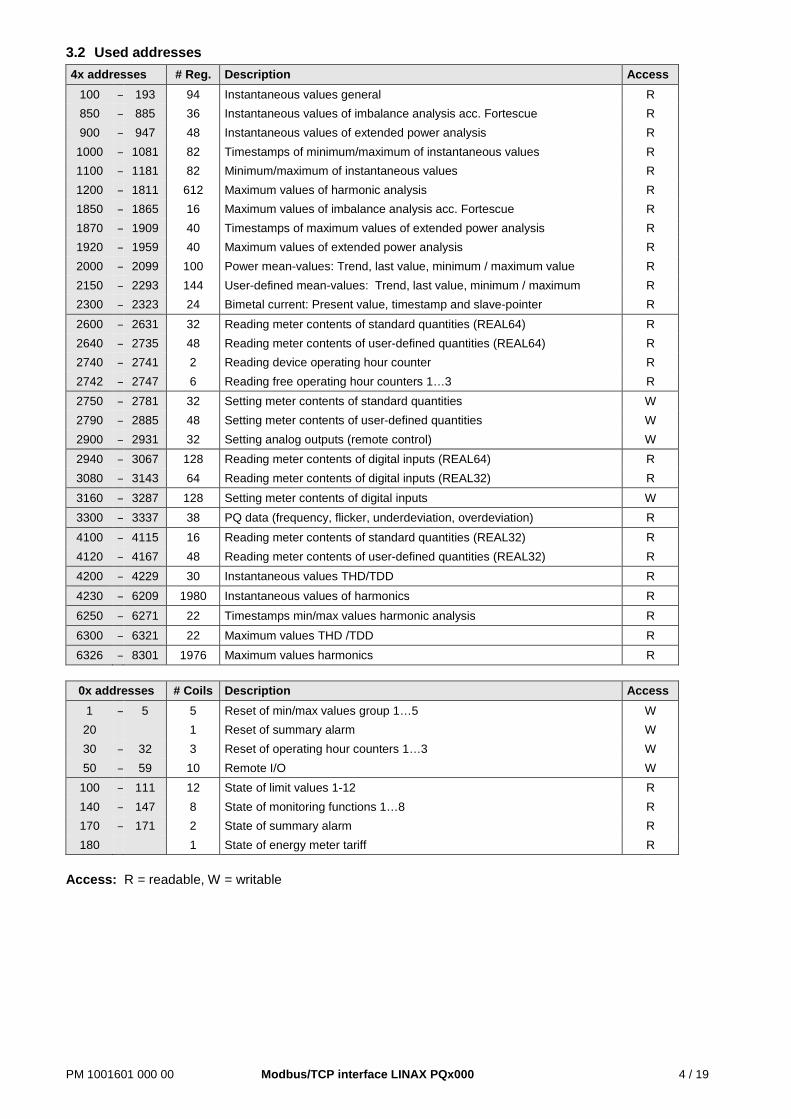
3.2 Used addresses 4x addresses # Reg. Description Access
100 – 193 94 Instantaneous values general R 850 – 885 36 Instantaneous values of imbalance analysis acc. Fortescue R 900 – 947 48 Instantaneous values of extended power analysis R
1000 – 1081 82 Timestamps of minimum/maximum of instantaneous values R 1100 – 1181 82 Minimum/maximum of instantaneous values R 1200 – 1811 612 Maximum values of harmonic analysis R 1850 – 1865 16 Maximum values of imbalance analysis acc. Fortescue R 1870 – 1909 40 Timestamps of maximum values of extended power analysis R 1920 – 1959 40 Maximum values of extended power analysis R 2000 – 2099 100 Power mean-values: Trend, last value, minimum / maximum value R 2150 – 2293 144 User-defined mean-values: Trend, last value, minimum / maximum R 2300 – 2323 24 Bimetal current: Present value, timestamp and slave-pointer R 2600 – 2631 32 Reading meter contents of standard quantities (REAL64) R 2640 – 2735 48 Reading meter contents of user-defined quantities (REAL64) R 2740 – 2741 2 Reading device operating hour counter R 2742 – 2747 6 Reading free operating hour counters 1…3 R 2750 – 2781 32 Setting meter contents of standard quantities W 2790 – 2885 48 Setting meter contents of user-defined quantities W 2900 – 2931 32 Setting analog outputs (remote control) W 2940 – 3067 128 Reading meter contents of digital inputs (REAL64) R 3080 – 3143 64 Reading meter contents of digital inputs (REAL32) R 3160 – 3287 128 Setting meter contents of digital inputs W 3300 – 3337 38 PQ data (frequency, flicker, underdeviation, overdeviation) R 4100 – 4115 16 Reading meter contents of standard quantities (REAL32) R 4120 – 4167 48 Reading meter contents of user-defined quantities (REAL32) R 4200 – 4229 30 Instantaneous values THD/TDD R 4230 – 6209 1980 Instantaneous values of harmonics R 6250 – 6271 22 Timestamps min/max values harmonic analysis R 6300 – 6321 22 Maximum values THD /TDD R 6326 – 8301 1976 Maximum values harmonics R
0x addresses # Coils Description Access
1 – 5 5 Reset of min/max values group 1…5 W 20 1 Reset of summary alarm W 30 – 32 3 Reset of operating hour counters 1…3 W 50 – 59 10 Remote I/O W
100 – 111 12 State of limit values 1-12 R 140 – 147 8 State of monitoring functions 1…8 R 170 – 171 2 State of summary alarm R 180 1 State of energy meter tariff R
Access: R = readable, W = writable
PM 1001601 000 00 Modbus/TCP interface LINAX PQx000 5 / 19
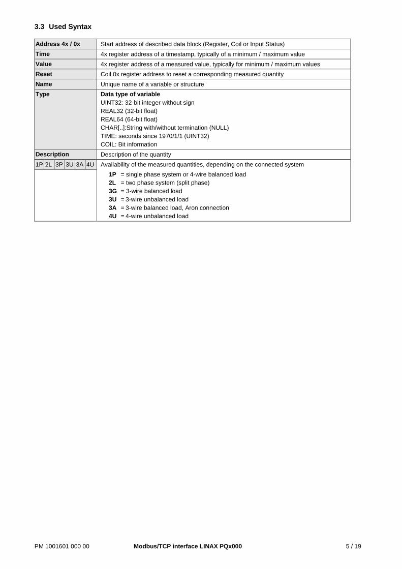
3.3 Used Syntax
Address 4x / 0x Start address of described data block (Register, Coil or Input Status) Time 4x register address of a timestamp, typically of a minimum / maximum value Value 4x register address of a measured value, typically for minimum / maximum values Reset Coil 0x register address to reset a corresponding measured quantity Name Unique name of a variable or structure Type Data type of variable
UINT32: 32-bit integer without sign REAL32 (32-bit float) REAL64 (64-bit float) CHAR[..]:String with/without termination (NULL) TIME: seconds since 1970/1/1 (UINT32) COIL: Bit information
Description Description of the quantity 1P 2L 3P 3U 3A 4U Availability of the measured quantities, depending on the connected system
1P = single phase system or 4-wire balanced load 2L = two phase system (split phase) 3G = 3-wire balanced load 3U = 3-wire unbalanced load 3A = 3-wire balanced load, Aron connection 4U = 4-wire unbalanced load
PM 1001601 000 00 Modbus/TCP interface LINAX PQx000 6 / 19
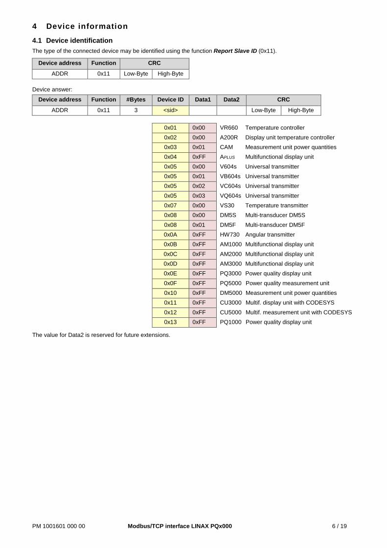
4 Device information
4.1 Device identification The type of the connected device may be identified using the function Report Slave ID (0x11).
Device address Function CRC
ADDR 0x11 Low-Byte High-Byte Device answer:
Device address Function #Bytes Device ID Data1 Data2 CRC
ADDR 0x11 3 <sid> Low-Byte High-Byte
0x01 0x00 VR660 Temperature controller
0x02 0x00 A200R Display unit temperature controller 0x03 0x01 CAM Measurement unit power quantities 0x04 0xFF APLUS Multifunctional display unit
0x05 0x00 V604s Universal transmitter 0x05 0x01 VB604s Universal transmitter 0x05 0x02 VC604s Universal transmitter
0x05 0x03 VQ604s Universal transmitter 0x07 0x00 VS30 Temperature transmitter 0x08 0x00 DM5S Multi-transducer DM5S
0x08 0x01 DM5F Multi-transducer DM5F 0x0A 0xFF HW730 Angular transmitter 0x0B 0xFF AM1000 Multifunctional display unit
0x0C 0xFF AM2000 Multifunctional display unit 0x0D 0xFF AM3000 Multifunctional display unit 0x0E 0xFF PQ3000 Power quality display unit
0x0F 0xFF PQ5000 Power quality measurement unit 0x10 0xFF DM5000 Measurement unit power quantities 0x11 0xFF CU3000 Multif. display unit with CODESYS
0x12 0xFF CU5000 Multif. measurement unit with CODESYS 0x13 0xFF PQ1000 Power quality display unit
The value for Data2 is reserved for future extensions.
PM 1001601 000 00 Modbus/TCP interface LINAX PQx000 7 / 19
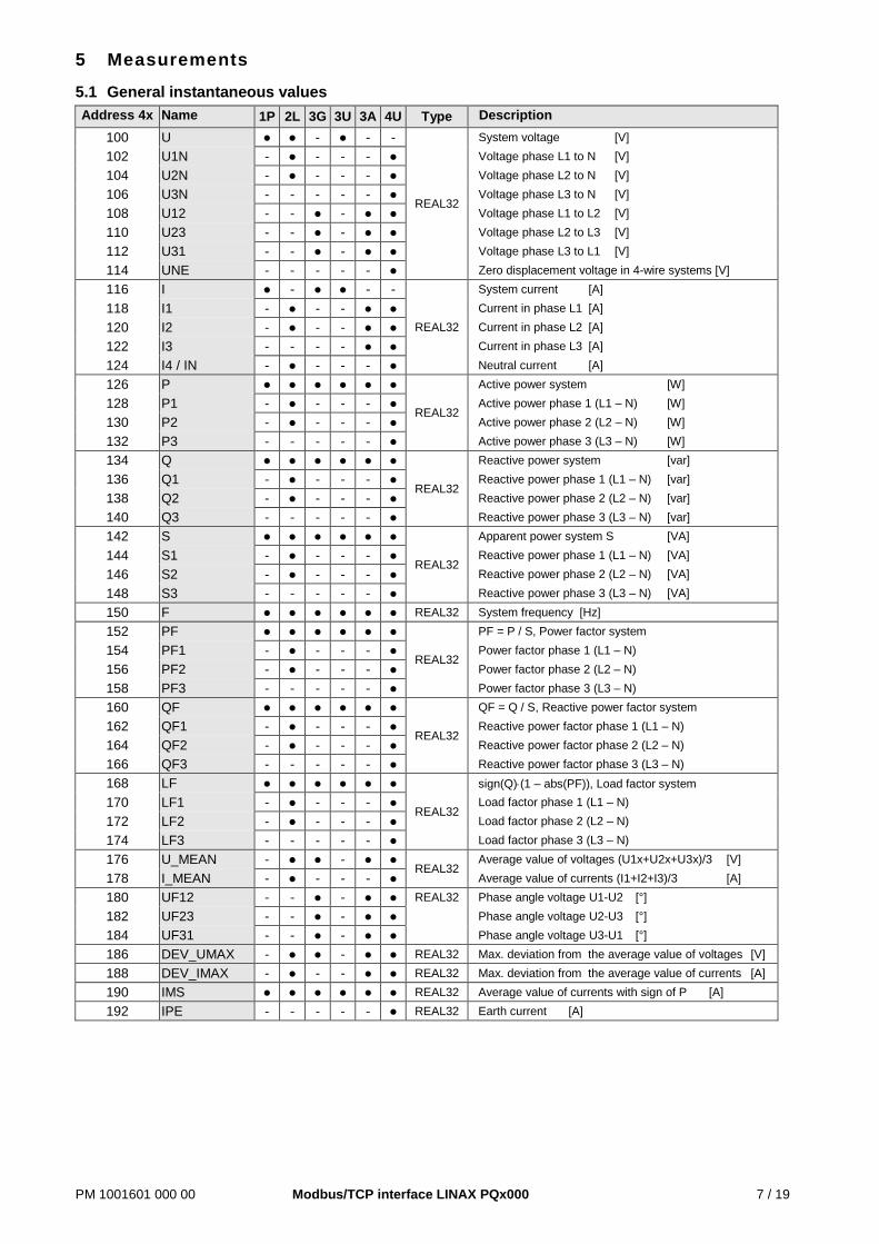
5 Measurements
5.1 General instantaneous values Address 4x Name 1P 2L 3G 3U 3A 4U Type Description
100 U ● ● - ● - -
REAL32
System voltage [V] 102 U1N - ● - - - ● Voltage phase L1 to N [V] 104 U2N - ● - - - ● Voltage phase L2 to N [V] 106 U3N - - - - - ● Voltage phase L3 to N [V] 108 U12 - - ● - ● ● Voltage phase L1 to L2 [V] 110 U23 - - ● - ● ● Voltage phase L2 to L3 [V] 112 U31 - - ● - ● ● Voltage phase L3 to L1 [V] 114 UNE - - - - - ● Zero displacement voltage in 4-wire systems [V] 116 I ● - ● ● - -
REAL32
System current [A] 118 I1 - ● - - ● ● Current in phase L1 [A] 120 I2 - ● - - ● ● Current in phase L2 [A] 122 I3 - - - - ● ● Current in phase L3 [A] 124 I4 / IN - ● - - - ● Neutral current [A] 126 P ● ● ● ● ● ●
REAL32
Active power system [W] 128 P1 - ● - - - ● Active power phase 1 (L1 – N) [W] 130 P2 - ● - - - ● Active power phase 2 (L2 – N) [W] 132 P3 - - - - - ● Active power phase 3 (L3 – N) [W] 134 Q ● ● ● ● ● ●
REAL32
Reactive power system [var] 136 Q1 - ● - - - ● Reactive power phase 1 (L1 – N) [var] 138 Q2 - ● - - - ● Reactive power phase 2 (L2 – N) [var] 140 Q3 - - - - - ● Reactive power phase 3 (L3 – N) [var] 142 S ● ● ● ● ● ●
REAL32
Apparent power system S [VA] 144 S1 - ● - - - ● Reactive power phase 1 (L1 – N) [VA] 146 S2 - ● - - - ● Reactive power phase 2 (L2 – N) [VA] 148 S3 - - - - - ● Reactive power phase 3 (L3 – N) [VA] 150 F ● ● ● ● ● ● REAL32 System frequency [Hz] 152 PF ● ● ● ● ● ●
REAL32
PF = P / S, Power factor system 154 PF1 - ● - - - ● Power factor phase 1 (L1 – N) 156 PF2 - ● - - - ● Power factor phase 2 (L2 – N) 158 PF3 - - - - - ● Power factor phase 3 (L3 – N) 160 QF ● ● ● ● ● ●
REAL32
QF = Q / S, Reactive power factor system 162 QF1 - ● - - - ● Reactive power factor phase 1 (L1 – N) 164 QF2 - ● - - - ● Reactive power factor phase 2 (L2 – N) 166 QF3 - - - - - ● Reactive power factor phase 3 (L3 – N) 168 LF ● ● ● ● ● ●
REAL32
sign(Q)⋅(1 – abs(PF)), Load factor system 170 LF1 - ● - - - ● Load factor phase 1 (L1 – N) 172 LF2 - ● - - - ● Load factor phase 2 (L2 – N) 174 LF3 - - - - - ● Load factor phase 3 (L3 – N) 176 U_MEAN - ● ● - ● ●
REAL32 Average value of voltages (U1x+U2x+U3x)/3 [V]
178 I_MEAN - ● - - - ● Average value of currents (I1+I2+I3)/3 [A] 180 UF12 - - ● - ● ● REAL32 Phase angle voltage U1-U2 [°] 182 UF23 - - ● - ● ● Phase angle voltage U2-U3 [°] 184 UF31 - - ● - ● ● Phase angle voltage U3-U1 [°] 186 DEV_UMAX - ● ● - ● ● REAL32 Max. deviation from the average value of voltages [V] 188 DEV_IMAX - ● - - ● ● REAL32 Max. deviation from the average value of currents [A] 190 IMS ● ● ● ● ● ● REAL32 Average value of currents with sign of P [A] 192 IPE - - - - - ● REAL32 Earth current [A]
PM 1001601 000 00 Modbus/TCP interface LINAX PQx000 8 / 19
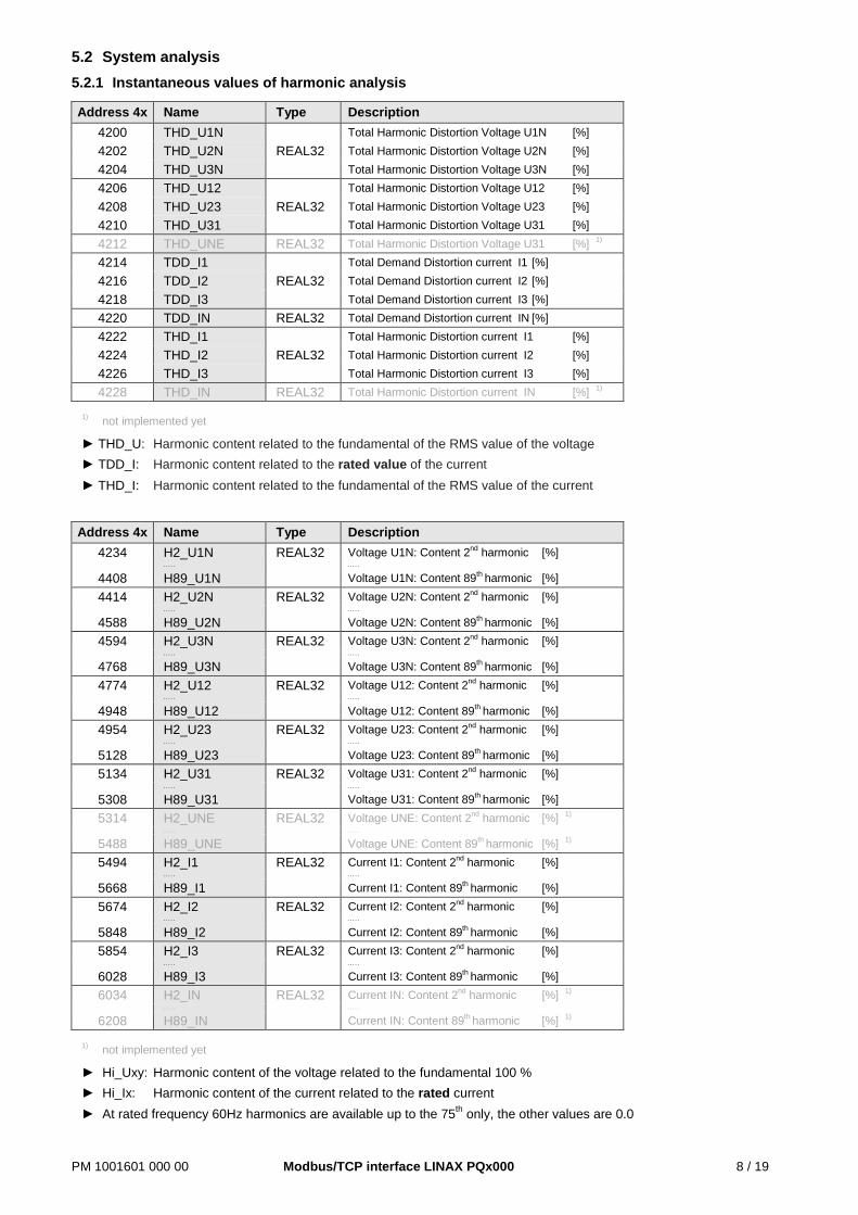
5.2 System analysis 5.2.1 Instantaneous values of harmonic analysis
Address 4x Name Type Description 4200 THD_U1N
REAL32 Total Harmonic Distortion Voltage U1N [%]
4202 THD_U2N Total Harmonic Distortion Voltage U2N [%] 4204 THD_U3N Total Harmonic Distortion Voltage U3N [%] 4206 THD_U12
REAL32 Total Harmonic Distortion Voltage U12 [%]
4208 THD_U23 Total Harmonic Distortion Voltage U23 [%] 4210 THD_U31 Total Harmonic Distortion Voltage U31 [%] 4212 THD_UNE REAL32 Total Harmonic Distortion Voltage U31 [%] 1) 4214 TDD_I1
REAL32 Total Demand Distortion current I1 [%]
4216 TDD_I2 Total Demand Distortion current I2 [%] 4218 TDD_I3 Total Demand Distortion current I3 [%] 4220 TDD_IN REAL32 Total Demand Distortion current IN [%] 4222 THD_I1
REAL32 Total Harmonic Distortion current I1 [%]
4224 THD_I2 Total Harmonic Distortion current I2 [%] 4226 THD_I3 Total Harmonic Distortion current I3 [%] 4228 THD_IN REAL32 Total Harmonic Distortion current IN [%] 1)
1) not implemented yet
► THD_U: Harmonic content related to the fundamental of the RMS value of the voltage ► TDD_I: Harmonic content related to the rated value of the current ► THD_I: Harmonic content related to the fundamental of the RMS value of the current
Address 4x Name Type Description 4234 H2_U1N REAL32 Voltage U1N: Content 2nd harmonic [%]
. . . . . . . . . .
4408 H89_U1N Voltage U1N: Content 89th harmonic [%] 4414 H2_U2N REAL32 Voltage U2N: Content 2nd harmonic [%]
. . . . . . . . . .
4588 H89_U2N Voltage U2N: Content 89th harmonic [%] 4594 H2_U3N REAL32 Voltage U3N: Content 2nd harmonic [%]
. . . . . . . . . .
4768 H89_U3N Voltage U3N: Content 89th harmonic [%] 4774 H2_U12 REAL32 Voltage U12: Content 2nd harmonic [%]
. . . . . . . . . .
4948 H89_U12 Voltage U12: Content 89th harmonic [%] 4954 H2_U23 REAL32 Voltage U23: Content 2nd harmonic [%]
. . . . . . . . . .
5128 H89_U23 Voltage U23: Content 89th harmonic [%] 5134 H2_U31 REAL32 Voltage U31: Content 2nd harmonic [%]
. . . . . . . . . .
5308 H89_U31 Voltage U31: Content 89th harmonic [%] 5314 H2_UNE REAL32 Voltage UNE: Content 2nd harmonic [%] 1)
. . . . . . . . . .
5488 H89_UNE Voltage UNE: Content 89th harmonic [%] 1) 5494 H2_I1 REAL32 Current I1: Content 2nd harmonic [%]
. . . . . . . . . .
5668 H89_I1 Current I1: Content 89th harmonic [%] 5674 H2_I2 REAL32 Current I2: Content 2nd harmonic [%]
. . . . . . . . . .
5848 H89_I2 Current I2: Content 89th harmonic [%] 5854 H2_I3 REAL32 Current I3: Content 2nd harmonic [%]
. . . . . . . . . .
6028 H89_I3 Current I3: Content 89th harmonic [%] 6034 H2_IN REAL32 Current IN: Content 2nd harmonic [%] 1)
. . . . . . . . . .
6208 H89_IN Current IN: Content 89th harmonic [%] 1)
1) not implemented yet
► Hi_Uxy: Harmonic content of the voltage related to the fundamental 100 % ► Hi_Ix: Harmonic content of the current related to the rated current ► At rated frequency 60Hz harmonics are available up to the 75th only, the other values are 0.0
PM 1001601 000 00 Modbus/TCP interface LINAX PQx000 9 / 19
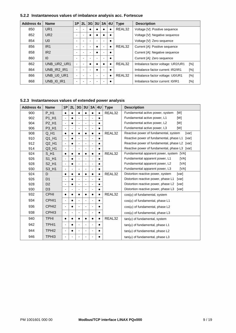
5.2.2 Instantaneous values of imbalance analysis acc. Fortescue
Address 4x Name 1P 2L 3G 3U 3A 4U Type Description 850 UR1 - - ● ● ● ● REAL32 Voltage [V]: Positive sequence
852 UR2 - - ● ● ● ● Voltage [V]: Negative sequence
854 U0 - - - - - ● Voltage [V]: Zero sequence
856 IR1 - - - ● - ● REAL32 Current [A]: Positive sequence
858 IR2 - - - ● - ● Current [A]: Negative sequence
860 I0 - - - - - ● Current [A]: Zero sequence
862 UNB_UR2_UR1 - - ● ● ● ● REAL32 Imbalance factor voltage: UR2/UR1 [%]
864 UNB_IR2_IR1 - - - ● - ● Imbalance factor current: IR2/IR1 [%]
866 UNB_U0_UR1 - - - - - ● REAL32 Imbalance factor voltage: U0/UR1 [%]
868 UNB_I0_IR1 - - - - - ● Imbalance factor current: I0/IR1 [%]
5.2.3 Instantaneous values of extended power analysis Address 4x Name 1P 2L 3G 3U 3A 4U Type Description
900 P_H1 ● ● ● ● ● ● REAL32 Fundamental active power, system [W]
902 P1_H1 - ● - - - ● Fundamental active power, L1 [W]
904 P2_H1 - ● - - - ● Fundamental active power, L2 [W]
906 P3_H1 - - - - - ● Fundamental active power, L3 [W]
908 Q_H1 ● ● ● ● ● ● REAL32 Reactive power of fundamental, system [var]
910 Q1_H1 - ● - - - ● Reactive power of fundamental, phase L1 [var]
912 Q2_H1 - ● - - - ● Reactive power of fundamental, phase L2 [var]
914 Q3_H1 - - - - - ● Reactive power of fundamental, phase L3 [var]
924 S_H1 ● ● ● ● ● ● REAL32 Fundamental apparent power, system [VA]
926 S1_H1 - ● - - - ● Fundamental apparent power, L1 [VA]
928 S2_H1 - ● - - - ● Fundamental apparent power, L2 [VA]
930 S3_H1 - - - - - ● Fundamental apparent power, L3 [VA]
924 D ● ● ● ● ● ● REAL32 Distortion reactive power, system [var]
926 D1 - ● - - - ● Distortion reactive power, phase L1 [var]
928 D2 - ● - - - ● Distortion reactive power, phase L2 [var]
930 D3 - - - - - ● Distortion reactive power, phase L3 [var]
932 CPHI ● ● ● ● ● ● REAL32 cos(ϕ) of fundamental, system
934 CPHI1 - ● - - - ● cos(ϕ) of fundamental, phase L1
936 CPHI2 - ● - - - ● cos(ϕ) of fundamental, phase L2
938 CPHI3 - - - - - ● cos(ϕ) of fundamental, phase L3
940 TPHI ● ● ● ● ● ● REAL32 tan(ϕ) of fundamental, system
942 TPHI1 - ● - - - ● tan(ϕ) of fundamental, phase L1
944 TPHI2 - ● - - - ● tan(ϕ) of fundamental, phase L2
946 TPHI3 - - - - - ● tan(ϕ) of fundamental, phase L3
PM 1001601 000 00 Modbus/TCP interface LINAX PQx000 10 / 19
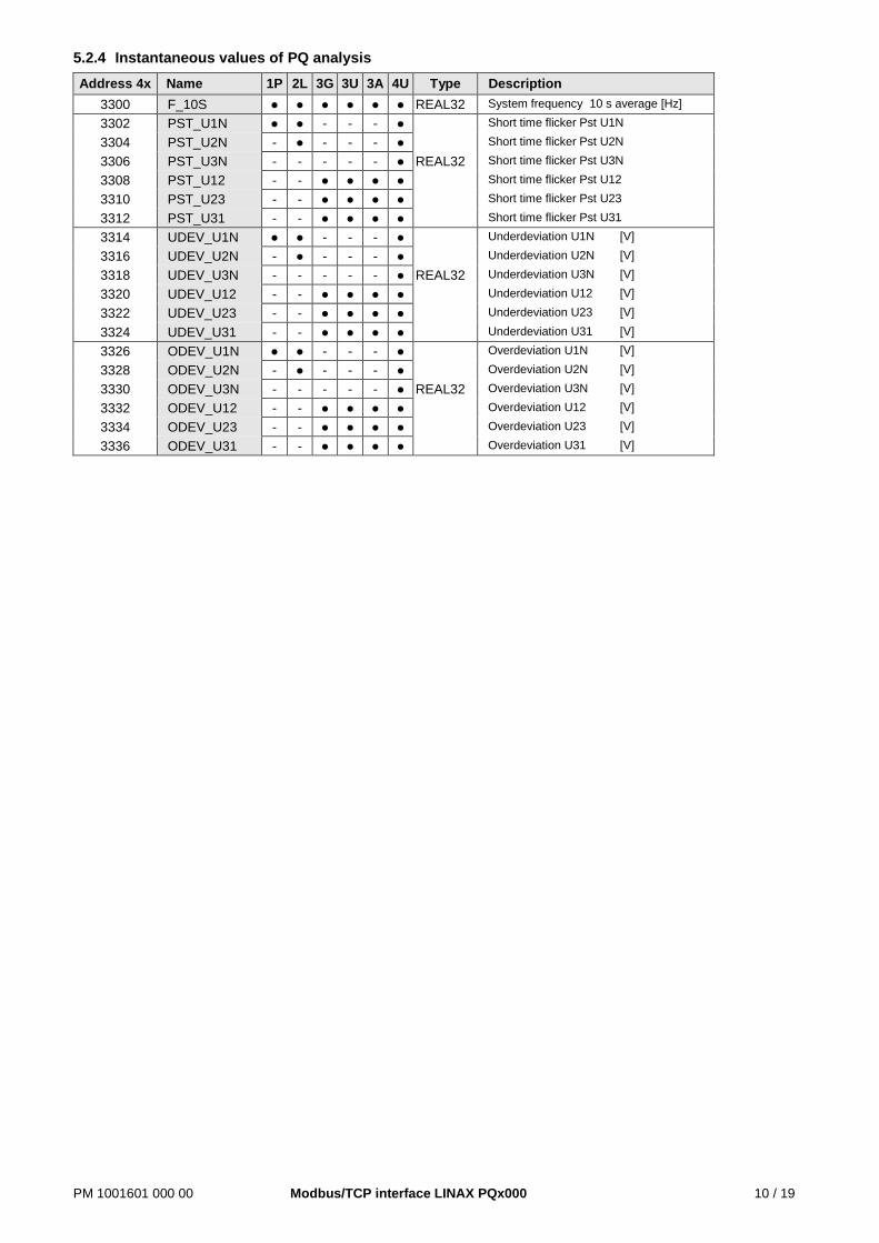
5.2.4 Instantaneous values of PQ analysis Address 4x Name 1P 2L 3G 3U 3A 4U Type Description
3300 F_10S ● ● ● ● ● ● REAL32 System frequency 10 s average [Hz]
3302 PST_U1N ● ● - - - ● Short time flicker Pst U1N
3304 PST_U2N - ● - - - ● Short time flicker Pst U2N
3306 PST_U3N - - - - - ● REAL32 Short time flicker Pst U3N
3308 PST_U12 - - ● ● ● ● Short time flicker Pst U12
3310 PST_U23 - - ● ● ● ● Short time flicker Pst U23
3312 PST_U31 - - ● ● ● ● Short time flicker Pst U31
3314 UDEV_U1N ● ● - - - ● Underdeviation U1N [V]
3316 UDEV_U2N - ● - - - ● Underdeviation U2N [V]
3318 UDEV_U3N - - - - - ● REAL32 Underdeviation U3N [V]
3320 UDEV_U12 - - ● ● ● ● Underdeviation U12 [V]
3322 UDEV_U23 - - ● ● ● ● Underdeviation U23 [V]
3324 UDEV_U31 - - ● ● ● ● Underdeviation U31 [V]
3326 ODEV_U1N ● ● - - - ● Overdeviation U1N [V]
3328 ODEV_U2N - ● - - - ● Overdeviation U2N [V]
3330 ODEV_U3N - - - - - ● REAL32 Overdeviation U3N [V]
3332 ODEV_U12 - - ● ● ● ● Overdeviation U12 [V]
3334 ODEV_U23 - - ● ● ● ● Overdeviation U23 [V]
3336 ODEV_U31 - - ● ● ● ● Overdeviation U31 [V]
PM 1001601 000 00 Modbus/TCP interface LINAX PQx000 11 / 19
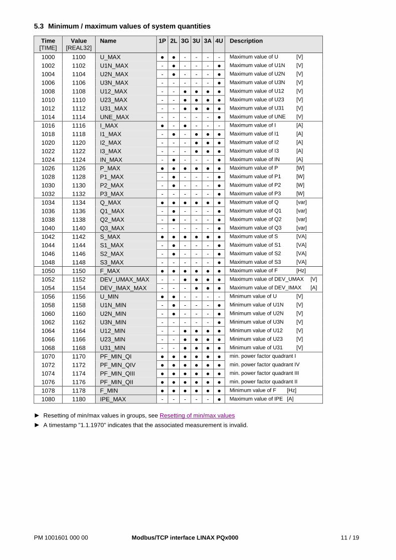
5.3 Minimum / maximum values of system quantities
Time [TIME]
Value [REAL32]
Name 1P 2L 3G 3U 3A 4U Description
1000 1100 U_MAX ● ● - - - - Maximum value of U [V]
1002 1102 U1N_MAX - ● - - - ● Maximum value of U1N [V]
1004 1104 U2N_MAX - ● - - - ● Maximum value of U2N [V]
1006 1106 U3N_MAX - - - - - ● Maximum value of U3N [V]
1008 1108 U12_MAX - - ● ● ● ● Maximum value of U12 [V]
1010 1110 U23_MAX - - ● ● ● ● Maximum value of U23 [V]
1012 1112 U31_MAX - - ● ● ● ● Maximum value of U31 [V]
1014 1114 UNE_MAX - - - - - ● Maximum value of UNE [V]
1016 1116 I_MAX ● - ● - - - Maximum value of I [A]
1018 1118 I1_MAX - ● - ● ● ● Maximum value of I1 [A]
1020 1120 I2_MAX - - - ● ● ● Maximum value of I2 [A]
1022 1122 I3_MAX - - - ● ● ● Maximum value of I3 [A]
1024 1124 IN_MAX - ● - - - ● Maximum value of IN [A]
1026 1126 P_MAX ● ● ● ● ● ● Maximum value of P [W]
1028 1128 P1_MAX - ● - - - ● Maximum value of P1 [W]
1030 1130 P2_MAX - ● - - - ● Maximum value of P2 [W]
1032 1132 P3_MAX - - - - - ● Maximum value of P3 [W]
1034 1134 Q_MAX ● ● ● ● ● ● Maximum value of Q [var]
1036 1136 Q1_MAX - ● - - - ● Maximum value of Q1 [var]
1038 1138 Q2_MAX - ● - - - ● Maximum value of Q2 [var]
1040 1140 Q3_MAX - - - - - ● Maximum value of Q3 [var]
1042 1142 S_MAX ● ● ● ● ● ● Maximum value of S [VA]
1044 1144 S1_MAX - ● - - - ● Maximum value of S1 [VA]
1046 1146 S2_MAX - ● - - - ● Maximum value of S2 [VA]
1048 1148 S3_MAX - - - - - ● Maximum value of S3 [VA]
1050 1150 F_MAX ● ● ● ● ● ● Maximum value of F [Hz]
1052 1152 DEV_UMAX_MAX - - ● ● ● ● Maximum value of DEV_UMAX [V]
1054 1154 DEV_IMAX_MAX - - - ● ● ● Maximum value of DEV_IMAX [A]
1056 1156 U_MIN ● ● - - - - Minimum value of U [V]
1058 1158 U1N_MIN - ● - - - ● Minimum value of U1N [V]
1060 1160 U2N_MIN - ● - - - ● Minimum value of U2N [V]
1062 1162 U3N_MIN - - - - - ● Minimum value of U3N [V]
1064 1164 U12_MIN - - ● ● ● ● Minimum value of U12 [V]
1066 1166 U23_MIN - - ● ● ● ● Minimum value of U23 [V]
1068 1168 U31_MIN - - ● ● ● ● Minimum value of U31 [V]
1070 1170 PF_MIN_QI ● ● ● ● ● ● min. power factor quadrant I
1072 1172 PF_MIN_QIV ● ● ● ● ● ● min. power factor quadrant IV
1074 1174 PF_MIN_QIII ● ● ● ● ● ● min. power factor quadrant III
1076 1176 PF_MIN_QII ● ● ● ● ● ● min. power factor quadrant II
1078 1178 F_MIN ● ● ● ● ● ● Minimum value of F [Hz]
1080 1180 IPE_MAX - - - - - ● Maximum value of IPE [A]
► Resetting of min/max values in groups, see Resetting of min/max values ► A timestamp "1.1.1970" indicates that the associated measurement is invalid.
PM 1001601 000 00 Modbus/TCP interface LINAX PQx000 12 / 19
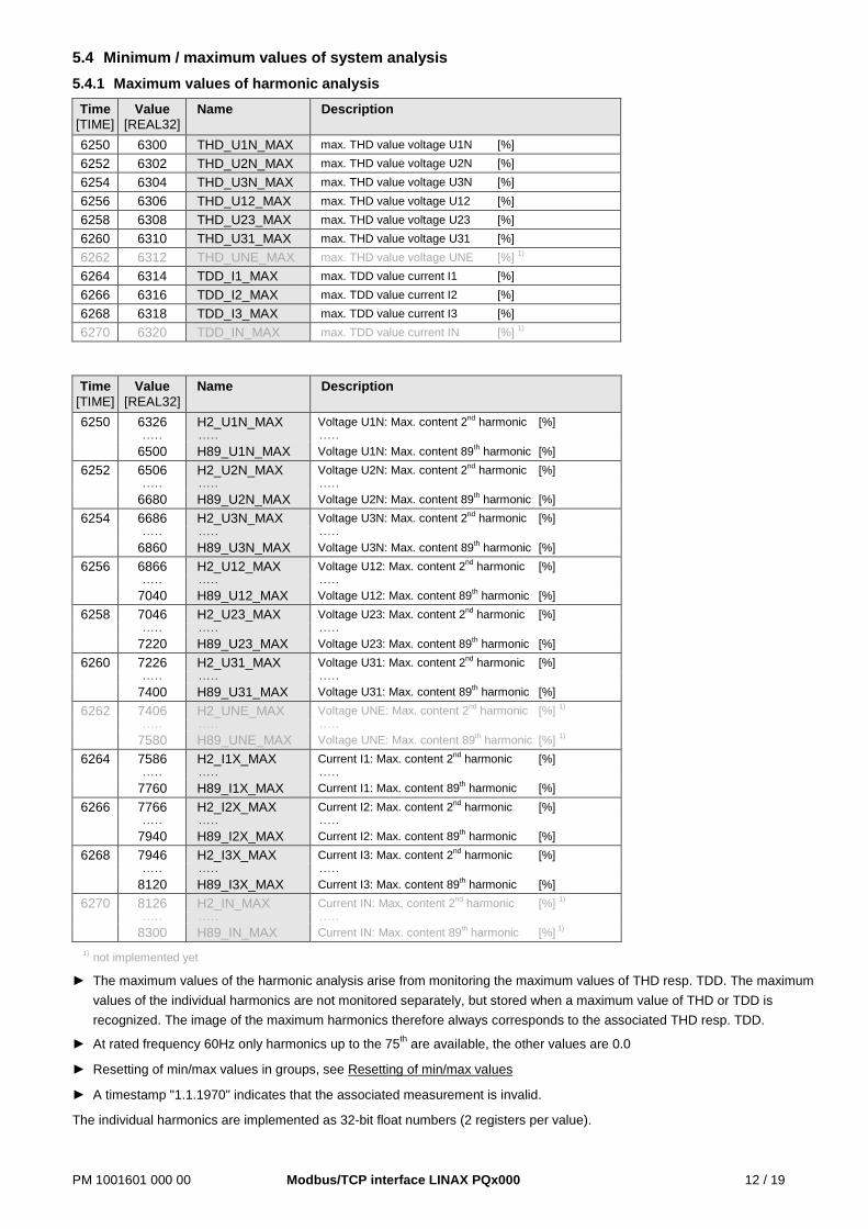
5.4 Minimum / maximum values of system analysis 5.4.1 Maximum values of harmonic analysis
Time [TIME]
Value [REAL32]
Name Description
6250 6300 THD_U1N_MAX max. THD value voltage U1N [%] 6252 6302 THD_U2N_MAX max. THD value voltage U2N [%] 6254 6304 THD_U3N_MAX max. THD value voltage U3N [%] 6256 6306 THD_U12_MAX max. THD value voltage U12 [%] 6258 6308 THD_U23_MAX max. THD value voltage U23 [%] 6260 6310 THD_U31_MAX max. THD value voltage U31 [%] 6262 6312 THD_UNE_MAX max. THD value voltage UNE [%] 1) 6264 6314 TDD_I1_MAX max. TDD value current I1 [%] 6266 6316 TDD_I2_MAX max. TDD value current I2 [%] 6268 6318 TDD_I3_MAX max. TDD value current I3 [%] 6270 6320 TDD_IN_MAX max. TDD value current IN [%] 1)
Time [TIME]
Value [REAL32]
Name Description
6250 6326 H2_U1N_MAX Voltage U1N: Max. content 2nd harmonic [%] . . . . . . . . . . . . . . .
6500 H89_U1N_MAX Voltage U1N: Max. content 89th harmonic [%] 6252 6506 H2_U2N_MAX Voltage U2N: Max. content 2nd harmonic [%]
. . . . . . . . . . . . . . .
6680 H89_U2N_MAX Voltage U2N: Max. content 89th harmonic [%] 6254 6686 H2_U3N_MAX Voltage U3N: Max. content 2nd harmonic [%]
. . . . . . . . . . . . . . .
6860 H89_U3N_MAX Voltage U3N: Max. content 89th harmonic [%] 6256 6866 H2_U12_MAX Voltage U12: Max. content 2nd harmonic [%]
. . . . . . . . . . . . . . .
7040 H89_U12_MAX Voltage U12: Max. content 89th harmonic [%] 6258 7046 H2_U23_MAX Voltage U23: Max. content 2nd harmonic [%]
. . . . . . . . . . . . . . .
7220 H89_U23_MAX Voltage U23: Max. content 89th harmonic [%] 6260 7226 H2_U31_MAX Voltage U31: Max. content 2nd harmonic [%]
. . . . . . . . . . . . . . .
7400 H89_U31_MAX Voltage U31: Max. content 89th harmonic [%] 6262 7406 H2_UNE_MAX Voltage UNE: Max. content 2nd harmonic [%] 1)
. . . . . . . . . . . . . . .
7580 H89_UNE_MAX Voltage UNE: Max. content 89th harmonic [%] 1) 6264 7586 H2_I1X_MAX Current I1: Max. content 2nd harmonic [%]
. . . . . . . . . . . . . . .
7760 H89_I1X_MAX Current I1: Max. content 89th harmonic [%] 6266 7766 H2_I2X_MAX Current I2: Max. content 2nd harmonic [%]
. . . . . . . . . . . . . . .
7940 H89_I2X_MAX Current I2: Max. content 89th harmonic [%] 6268 7946 H2_I3X_MAX Current I3: Max. content 2nd harmonic [%]
. . . . . . . . . . . . . . .
8120 H89_I3X_MAX Current I3: Max. content 89th harmonic [%] 6270 8126 H2_IN_MAX Current IN: Max. content 2nd harmonic [%] 1)
. . . . . . . . . . . . . . .
8300 H89_IN_MAX Current IN: Max. content 89th harmonic [%] 1) 1) not implemented yet
► The maximum values of the harmonic analysis arise from monitoring the maximum values of THD resp. TDD. The maximum values of the individual harmonics are not monitored separately, but stored when a maximum value of THD or TDD is recognized. The image of the maximum harmonics therefore always corresponds to the associated THD resp. TDD.
► At rated frequency 60Hz only harmonics up to the 75th are available, the other values are 0.0
► Resetting of min/max values in groups, see Resetting of min/max values
► A timestamp "1.1.1970" indicates that the associated measurement is invalid.
The individual harmonics are implemented as 32-bit float numbers (2 registers per value).
PM 1001601 000 00 Modbus/TCP interface LINAX PQx000 13 / 19
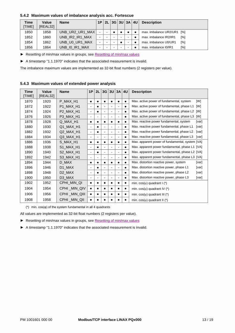
5.4.2 Maximum values of imbalance analysis acc. Fortescue Time
[TIME] Value
[REAL32] Name 1P 2L 3G 3U 3A 4U Description
1850 1858 UNB_UR2_UR1_MAX - - ● ● ● ● max. imbalance UR2/UR1 [%] 1852 1860 UNB_IR2_IR1_MAX - - - - - ● max. imbalance IR2/IR1 [%] 1854 1862 UNB_U0_UR1_MAX - - - ● - ● max. imbalance U0/UR1 [%] 1856 1864 UNB_I0_IR1_MAX - - - - - ● max. imbalance I0/IR1 [%]
► Resetting of min/max values in groups, see Resetting of min/max values
► A timestamp "1.1.1970" indicates that the associated measurement is invalid.
The imbalance maximum values are implemented as 32-bit float numbers (2 registers per value).
5.4.3 Maximum values of extended power analysis
Time [TIME]
Value [REAL32]
Name 1P 2L 3G 3U 3A 4U Description
1870 1920 P_MAX_H1 ● ● ● ● ● ● Max. active power of fundamental, system [W]
1872 1922 P1_MAX_H1 - ● - - - ● Max. active power of fundamental, phase L1 [W]
1874 1924 P2_MAX_H1 - ● - - - ● Max. active power of fundamental, phase L2 [W]
1876 1926 P3_MAX_H1 - - - - - ● Max. active power of fundamental, phase L3 [W]
1878 1928 Q_MAX_H1 ● ● ● ● ● ● Max. reactive power fundamental, system [var]
1880 1930 Q1_MAX_H1 - ● - - - ● Max. reactive power fundamental, phase L1 [var]
1882 1932 Q2_MAX_H1 - ● - - - ● Max. reactive power fundamental, phase L2 [var]
1884 1934 Q3_MAX_H1 - - - - - ● Max. reactive power fundamental, phase L3 [var]
1886 1936 S_MAX_H1 ● ● ● ● ● ● Max. apparent power of fundamental, system [VA]
1888 1938 S1_MAX_H1 - ● - - - ● Max. apparent power fundamental, phase L1 [VA]
1890 1940 S2_MAX_H1 - ● - - - ● Max. apparent power fundamental, phase L2 [VA]
1892 1942 S3_MAX_H1 - - - - - ● Max. apparent power fundamental, phase L3 [VA]
1894 1944 D_MAX ● ● ● ● ● ● Max. distortion reactive power, system [var]
1896 1946 D1_MAX - ● - - - ● Max. distortion reactive power, phase L1 [var]
1898 1948 D2_MAX - ● - - - ● Max. distortion reactive power, phase L2 [var]
1900 1950 D3_MAX - - - - - ● Max. distortion reactive power, phase L3 [var]
1902 1952 CPHI_MIN_QI ● ● ● ● ● ● min. cos(ϕ) quadrant I (*)
1904 1954 CPHI _MIN_QIV ● ● ● ● ● ● min. cos(ϕ) quadrant IV (*)
1906 1956 CPHI _MIN_QIII ● ● ● ● ● ● min. cos(ϕ) quadrant III (*)
1908 1958 CPHI _MIN_QII ● ● ● ● ● ● min. cos(ϕ) quadrant II (*)
(*) min. cos(φ) of the system fundamental in all 4 quadrants
All values are implemented as 32-bit float numbers (2 registers per value).
► Resetting of min/max values in groups, see Resetting of min/max values
► A timestamp "1.1.1970" indicates that the associated measurement is invalid.
PM 1001601 000 00 Modbus/TCP interface LINAX PQx000 14 / 19
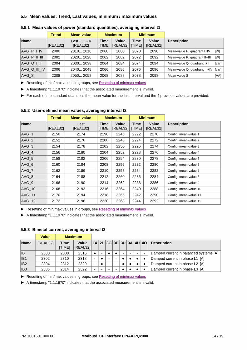
5.5 Mean values: Trend, Last values, minimum / maximum values 5.5.1 Mean values of power (standard quantities), averaging interval t1 Trend Mean-value Maximum Minimum Name
[REAL32] Last ...... - 4 [REAL32]
Time [TIME]
Value [REAL32]
Time [TIME]
Value [REAL32]
Description
AVG_P_I_IV 2000 2010... 2018 2060 2080 2070 2090 Mean-value P, quadrant I+IV [W]
AVG_P_II_III 2002 2020... 2028 2062 2082 2072 2092 Mean-value P, quadrant II+III [W]
AVG_Q_I_II 2004 2030... 2038 2064 2084 2074 2094 Mean-value Q, quadrant I+II [var]
AVG_Q_III_IV 2006 2040... 2048 2066 2086 2076 2096 Mean-value Q, quadrant III+IV [var]
AVG_S 2008 2050... 2058 2068 2088 2078 2098 Mean-value S [VA]
► Resetting of min/max values in groups, see Resetting of min/max values
► A timestamp "1.1.1970" indicates that the associated measurement is invalid.
► For each of the standard quantities the mean-value for the last interval and the 4 previous values are provided.
5.5.2 User-defined mean values, averaging interval t2 Trend Mean-value Maximum Minimum Name
[REAL32] Last
[REAL32] Time
[TIME] Value
[REAL32] Time
[TIME] Value
[REAL32] Description
AVG_1 2150 2174 2198 2246 2222 2270 Config. mean-value 1
AVG_2 2152 2176 2200 2248 2224 2272 Config. mean-value 2
AVG_3 2154 2178 2202 2250 2226 2274 Config. mean-value 3
AVG_4 2156 2180 2204 2252 2228 2276 Config. mean-value 4
AVG_5 2158 2182 2206 2254 2230 2278 Config. mean-value 5
AVG_6 2160 2184 2208 2256 2232 2280 Config. mean-value 6
AVG_7 2162 2186 2210 2258 2234 2282 Config. mean-value 7
AVG_8 2164 2188 2212 2260 2236 2284 Config. mean-value 8
AVG_9 2166 2190 2214 2262 2238 2286 Config. mean-value 9
AVG_10 2168 2192 2216 2264 2240 2288 Config. mean-value 10
AVG_11 2170 2194 2218 2266 2242 2290 Config. mean-value 11
AVG_12 2172 2196 2220 2268 2244 2292 Config. mean-value 12
► Resetting of min/max values in groups, see Resetting of min/max values ► A timestamp "1.1.1970" indicates that the associated measurement is invalid. 5.5.3 Bimetal current, averaging interval t3 Value Maximum Name [REAL32] Time
[TIME] Value
[REAL32] 14 2L 3G 3P 3U 3A 4U 4O Description
IB 2300 2308 2316 ● - ● ● - - - - Damped current in balanced systems [A] IB1 2302 2310 2318 - ● - - ● ● ● ● Damped current in phase L1 [A] IB2 2304 2312 2320 - ● - - ● ● ● ● Damped current in phase L2 [A] IB3 2306 2314 2322 - - - - ● ● ● ● Damped current in phase L3 [A]
► Resetting of min/max values in groups, see Resetting of min/max values ► A timestamp "1.1.1970" indicates that the associated measurement is invalid.
PM 1001601 000 00 Modbus/TCP interface LINAX PQx000 15 / 19
5.6 Resetting of min/max values Min/max values may be reset in groups via coils.
Address 0x Name Type Group to be reset 1 MM_RES1 COIL - Min/max of voltages, currents, frequency
2 MM_RES2 COIL - Min/max of active, reactive, apparent power - Min/max of fundamental and distortion reactive power - Minimum values of load factors, cosϕ
3 MM_RES3 COIL - Min/Max values of power mean-values / configurable mean-values - Bimetal slave pointers
4 MM_RES4 COIL - Maximum of THD U/I, TDD I, individual harmonics
5 MM_RES5 COIL - Maximum values of imbalance analysis
5.7 Present state of limit values Address 0x Name Type Description
100 LIMIT_ST1 COIL State of limit value 1 (0=OFF, 1=ON)
read
onl
y
101 LIMIT_ST2 State of limit value 2 (0=OFF, 1=ON) 102 LIMIT_ST3 State of limit value 3 (0=OFF, 1=ON) 103 LIMIT_ST4 State of limit value 4 (0=OFF, 1=ON) 104 LIMIT_ST5 State of limit value 5 (0=OFF, 1=ON) 105 LIMIT_ST6 State of limit value 6 (0=OFF, 1=ON) 106 LIMIT_ST7 State of limit value 7 (0=OFF, 1=ON) 107 LIMIT_ST8 State of limit value 8 (0=OFF, 1=ON) 108 LIMIT_ST9 State of limit value 9 (0=OFF, 1=ON) 109 LIMIT_ST10 State of limit value 10 (0=OFF, 1=ON) 110 LIMIT_ST11 State of limit value 11 (0=OFF, 1=ON) 111 LIMIT_ST12 State of limit value 12 (0=OFF, 1=ON)
5.8 Present state of monitoring functions Address 0x Name Type Description
140 MFUN_ST1 COIL State of monitoring function 1 (0=inactive, 1=active)
read
onl
y
141 MFUN_ST2 State of monitoring function 2 (0=inactive, 1=active) 142 MFUN_ST3 State of monitoring function 3 (0=inactive, 1=active) 143 MFUN_ST4 State of monitoring function 4 (0=inactive, 1=active) 144 MFUN_ST5 State of monitoring function 5 (0=inactive, 1=active) 145 MFUN_ST6 State of monitoring function 6 (0=inactive, 1=active) 146 MFUN_ST7 State of monitoring function 7 (0=inactive, 1=active) 147 MFUN_ST8 State of monitoring function 8 (0=inactive, 1=active)
5.9 Summary alarm The summary alarm represents the over-all alarm state of the device. It is the AND combination of all defined monitoring functions enabled for the summary alarm and is active if at least one function is in the alarm state. The summary alarm is used for showing the alarm state on the display and can also activate a logic output (e.g. digital output or relay).
Via interface the summary alarm may be influenced as follows:
• Resetting the logic output of the summary alarm: The output will be reset even if there summary alarm is active.
Address 0x Name Type Description 170 SA_STATE COIL State of summary alarm (0=inactive, 1=active)
171 SA_RES_STATE COIL Logic output of summary alarm (0=inactive or reset, 1=active)
20 SA_RESET COIL For Resetting the logic output of the summary alarm
PM 1001601 000 00 Modbus/TCP interface LINAX PQx000 16 / 19
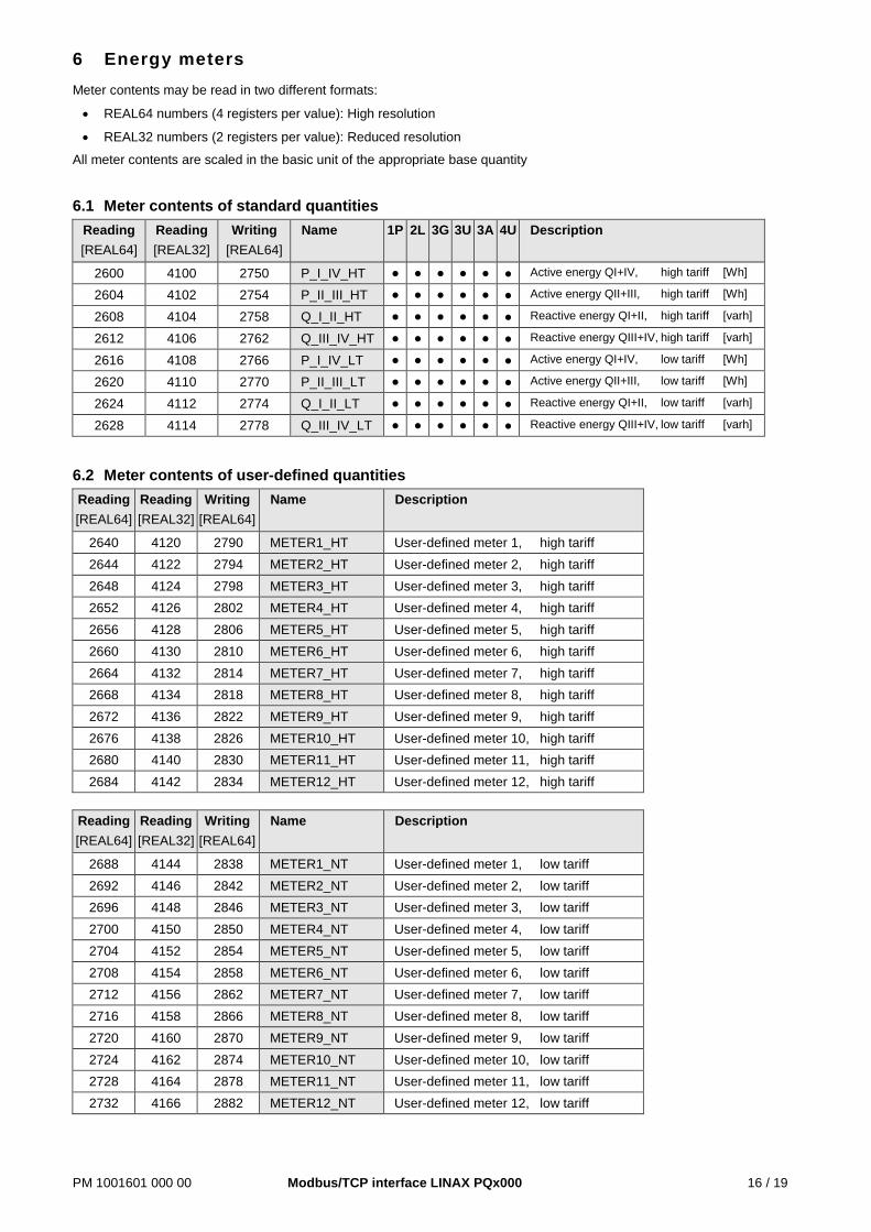
6 Energy meters Meter contents may be read in two different formats:
• REAL64 numbers (4 registers per value): High resolution
• REAL32 numbers (2 registers per value): Reduced resolution
All meter contents are scaled in the basic unit of the appropriate base quantity
6.1 Meter contents of standard quantities Reading [REAL64]
Reading [REAL32]
Writing [REAL64]
Name 1P 2L 3G 3U 3A 4U Description
2600 4100 2750 P_I_IV_HT ● ● ● ● ● ● Active energy QI+IV, high tariff [Wh]
2604 4102 2754 P_II_III_HT ● ● ● ● ● ● Active energy QII+III, high tariff [Wh]
2608 4104 2758 Q_I_II_HT ● ● ● ● ● ● Reactive energy QI+II, high tariff [varh]
2612 4106 2762 Q_III_IV_HT ● ● ● ● ● ● Reactive energy QIII+IV, high tariff [varh]
2616 4108 2766 P_I_IV_LT ● ● ● ● ● ● Active energy QI+IV, low tariff [Wh]
2620 4110 2770 P_II_III_LT ● ● ● ● ● ● Active energy QII+III, low tariff [Wh]
2624 4112 2774 Q_I_II_LT ● ● ● ● ● ● Reactive energy QI+II, low tariff [varh]
2628 4114 2778 Q_III_IV_LT ● ● ● ● ● ● Reactive energy QIII+IV, low tariff [varh]
6.2 Meter contents of user-defined quantities Reading [REAL64]
Reading [REAL32]
Writing [REAL64]
Name Description
2640 4120 2790 METER1_HT User-defined meter 1, high tariff 2644 4122 2794 METER2_HT User-defined meter 2, high tariff 2648 4124 2798 METER3_HT User-defined meter 3, high tariff 2652 4126 2802 METER4_HT User-defined meter 4, high tariff 2656 4128 2806 METER5_HT User-defined meter 5, high tariff 2660 4130 2810 METER6_HT User-defined meter 6, high tariff 2664 4132 2814 METER7_HT User-defined meter 7, high tariff 2668 4134 2818 METER8_HT User-defined meter 8, high tariff 2672 4136 2822 METER9_HT User-defined meter 9, high tariff 2676 4138 2826 METER10_HT User-defined meter 10, high tariff 2680 4140 2830 METER11_HT User-defined meter 11, high tariff 2684 4142 2834 METER12_HT User-defined meter 12, high tariff
Reading [REAL64]
Reading [REAL32]
Writing [REAL64]
Name Description
2688 4144 2838 METER1_NT User-defined meter 1, low tariff 2692 4146 2842 METER2_NT User-defined meter 2, low tariff 2696 4148 2846 METER3_NT User-defined meter 3, low tariff 2700 4150 2850 METER4_NT User-defined meter 4, low tariff 2704 4152 2854 METER5_NT User-defined meter 5, low tariff 2708 4154 2858 METER6_NT User-defined meter 6, low tariff 2712 4156 2862 METER7_NT User-defined meter 7, low tariff 2716 4158 2866 METER8_NT User-defined meter 8, low tariff 2720 4160 2870 METER9_NT User-defined meter 9, low tariff 2724 4162 2874 METER10_NT User-defined meter 10, low tariff 2728 4164 2878 METER11_NT User-defined meter 11, low tariff 2732 4166 2882 METER12_NT User-defined meter 12, low tariff
PM 1001601 000 00 Modbus/TCP interface LINAX PQx000 17 / 19
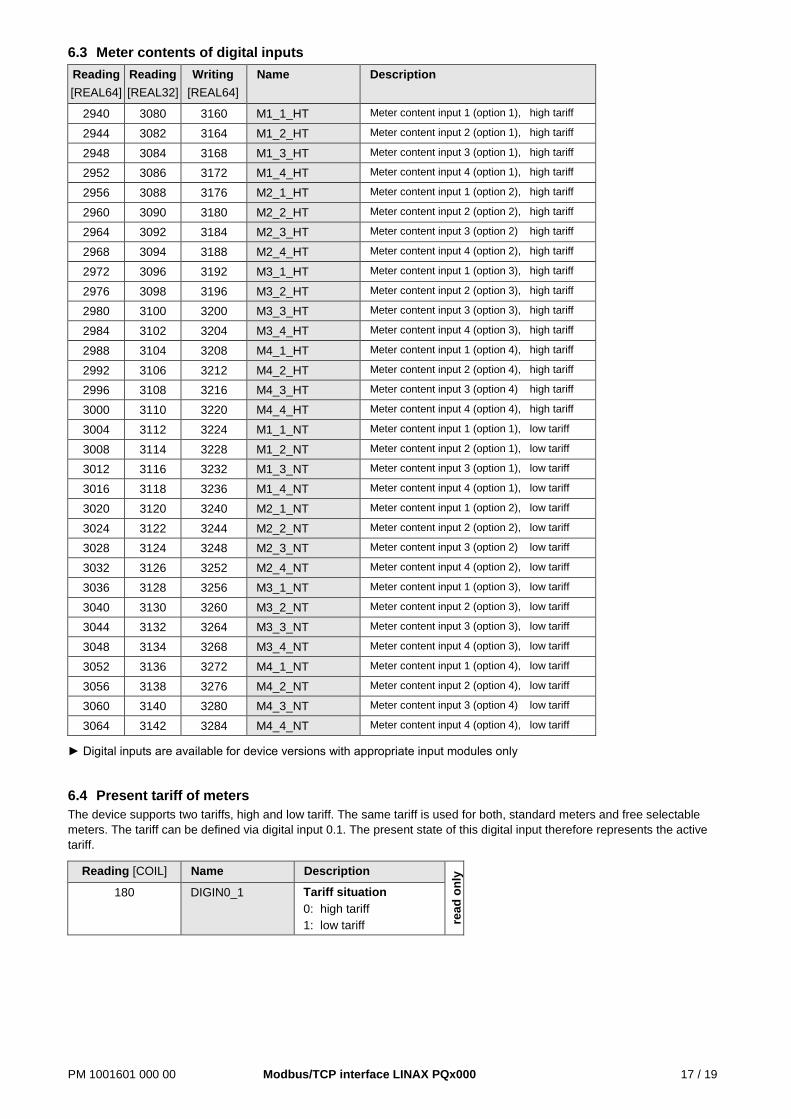
6.3 Meter contents of digital inputs Reading [REAL64]
Reading [REAL32]
Writing [REAL64]
Name Description
2940 3080 3160 M1_1_HT Meter content input 1 (option 1), high tariff
2944 3082 3164 M1_2_HT Meter content input 2 (option 1), high tariff
2948 3084 3168 M1_3_HT Meter content input 3 (option 1), high tariff
2952 3086 3172 M1_4_HT Meter content input 4 (option 1), high tariff
2956 3088 3176 M2_1_HT Meter content input 1 (option 2), high tariff
2960 3090 3180 M2_2_HT Meter content input 2 (option 2), high tariff
2964 3092 3184 M2_3_HT Meter content input 3 (option 2) high tariff
2968 3094 3188 M2_4_HT Meter content input 4 (option 2), high tariff
2972 3096 3192 M3_1_HT Meter content input 1 (option 3), high tariff
2976 3098 3196 M3_2_HT Meter content input 2 (option 3), high tariff
2980 3100 3200 M3_3_HT Meter content input 3 (option 3), high tariff
2984 3102 3204 M3_4_HT Meter content input 4 (option 3), high tariff
2988 3104 3208 M4_1_HT Meter content input 1 (option 4), high tariff
2992 3106 3212 M4_2_HT Meter content input 2 (option 4), high tariff
2996 3108 3216 M4_3_HT Meter content input 3 (option 4) high tariff
3000 3110 3220 M4_4_HT Meter content input 4 (option 4), high tariff
3004 3112 3224 M1_1_NT Meter content input 1 (option 1), low tariff
3008 3114 3228 M1_2_NT Meter content input 2 (option 1), low tariff
3012 3116 3232 M1_3_NT Meter content input 3 (option 1), low tariff
3016 3118 3236 M1_4_NT Meter content input 4 (option 1), low tariff
3020 3120 3240 M2_1_NT Meter content input 1 (option 2), low tariff
3024 3122 3244 M2_2_NT Meter content input 2 (option 2), low tariff
3028 3124 3248 M2_3_NT Meter content input 3 (option 2) low tariff
3032 3126 3252 M2_4_NT Meter content input 4 (option 2), low tariff
3036 3128 3256 M3_1_NT Meter content input 1 (option 3), low tariff
3040 3130 3260 M3_2_NT Meter content input 2 (option 3), low tariff
3044 3132 3264 M3_3_NT Meter content input 3 (option 3), low tariff
3048 3134 3268 M3_4_NT Meter content input 4 (option 3), low tariff
3052 3136 3272 M4_1_NT Meter content input 1 (option 4), low tariff
3056 3138 3276 M4_2_NT Meter content input 2 (option 4), low tariff
3060 3140 3280 M4_3_NT Meter content input 3 (option 4) low tariff
3064 3142 3284 M4_4_NT Meter content input 4 (option 4), low tariff
► Digital inputs are available for device versions with appropriate input modules only
6.4 Present tariff of meters The device supports two tariffs, high and low tariff. The same tariff is used for both, standard meters and free selectable meters. The tariff can be defined via digital input 0.1. The present state of this digital input therefore represents the active tariff.
Reading [COIL] Name Description
read
onl
y
180 DIGIN0_1 Tariff situation 0: high tariff 1: low tariff
PM 1001601 000 00 Modbus/TCP interface LINAX PQx000 18 / 19
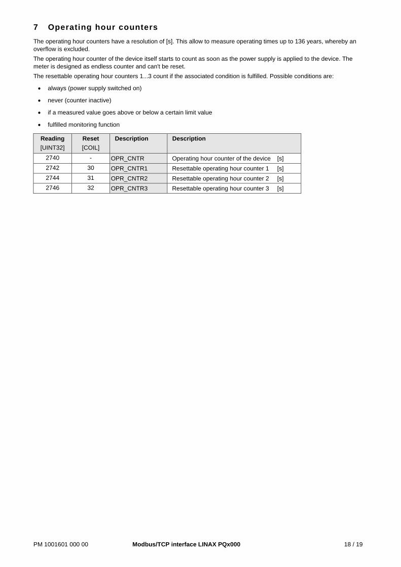
7 Operating hour counters The operating hour counters have a resolution of [s]. This allow to measure operating times up to 136 years, whereby an overflow is excluded. The operating hour counter of the device itself starts to count as soon as the power supply is applied to the device. The meter is designed as endless counter and can't be reset. The resettable operating hour counters 1...3 count if the associated condition is fulfilled. Possible conditions are:
• always (power supply switched on)
• never (counter inactive)
• if a measured value goes above or below a certain limit value
• fulfilled monitoring function
Reading [UINT32]
Reset [COIL]
Description Description
2740 - OPR_CNTR Operating hour counter of the device [s] 2742 30 OPR_CNTR1 Resettable operating hour counter 1 [s] 2744 31 OPR_CNTR2 Resettable operating hour counter 2 [s] 2746 32 OPR_CNTR3 Resettable operating hour counter 3 [s]
PM 1001601 000 00 Modbus/TCP interface LINAX PQx000 19 / 19
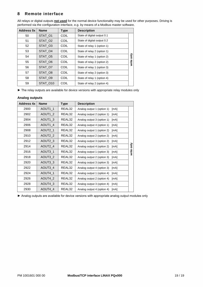
8 Remote interface All relays or digital outputs not used for the normal device functionality may be used for other purposes. Driving is performed via the configuration interface, e.g. by means of a Modbus master software.
Address 0x Name Type Description 50 STAT_O1 COIL State of digital output 0.1
writ
e on
ly
51 STAT_O2 COIL State of digital output 0.2
52 STAT_O3 COIL State of relay 1 (option 1)
53 STAT_O4 COIL State of relay 2 (option 1)
54 STAT_O5 COIL State of relay 1 (option 2)
55 STAT_O6 COIL State of relay 2 (option 2)
56 STAT_O7 COIL State of relay 1 (option 3)
57 STAT_O8 COIL State of relay 2 (option 3)
58 STAT_O9 COIL State of relay 1 (option 4)
59 STAT_O10 COIL State of relay 2 (option 4)
► The relay outputs are available for device versions with appropriate relay modules only Analog outputs
Address 4x Name Type Description 2900 AOUT1_1 REAL32 Analog output 1 (option 1) [mA]
writ
e on
ly
2902 AOUT1_2 REAL32 Analog output 2 (option 1) [mA]
2904 AOUT1_3 REAL32 Analog output 3 (option 1) [mA]
2906 AOUT1_4 REAL32 Analog output 4 (option 1) [mA]
2908 AOUT2_1 REAL32 Analog output 1 (option 2) [mA]
2910 AOUT2_2 REAL32 Analog output 2 (option 2) [mA]
2912 AOUT2_3 REAL32 Analog output 3 (option 2) [mA]
2914 AOUT2_4 REAL32 Analog output 4 (option 2) [mA]
2916 AOUT3_1 REAL32 Analog output 1 (option 3) [mA]
2918 AOUT3_2 REAL32 Analog output 2 (option 3) [mA]
2920 AOUT3_3 REAL32 Analog output 3 (option 3) [mA]
2922 AOUT3_4 REAL32 Analog output 4 (option 3) [mA]
2924 AOUT4_1 REAL32 Analog output 1 (option 4) [mA]
2926 AOUT4_2 REAL32 Analog output 2 (option 4) [mA]
2928 AOUT4_3 REAL32 Analog output 3 (option 4) [mA]
2930 AOUT4_4 REAL32 Analog output 4 (option 4) [mA]
► Analog outputs are available for device versions with appropriate analog output modules only


![Serial Communication [Modbus Version] Operation Manual ......RCP6 (PLC Unit) ERC2, ERC3 Serial Communication [Modbus Version] Operation Manual, Ninth Edition . Modbus . Modbus Please](https://static.fdocuments.in/doc/165x107/5e6d973e9fc0481438519dec/serial-communication-modbus-version-operation-manual-rcp6-plc-unit-erc2.jpg)