· 71/—Zsetyts KSP -4 KSP- (KSP -1B) 3 KSP KSP 1 2 KSP- 2 KSP-I : 7 mm 7mm . : I 1-7—5 (GPN)
Sludge-PumP-SyStemS muck PumPS
overview
cONteNtS
Sludge PumPS
06 | 07 Fields of application KSP
08 | 09 KSP / TAP / EHS / SD -Abbreviations explained
10 | 11 Poppelt Valve System / Rock Valve System
12 | 13 KSP 5 HD / KSP 10 HDV
14 | 15 KSP 12 HD / KSP 17 HDV
16 | 17 KSP 25 HDR / KSP 40 HD
18 | 19 KSP 45 HD / KSP 50 HDV
20 | 21 KSP 65 HDR / KSP 80 HDV
22 | 23 KSP 110 HD / 140 HDV
24 | 25 KSP 220 HDR / KSP 315 XL
muck PumPS
26 | 27 TAP 30 R / TAP 50 R / TAP 90 R / TAP 110 R
Hydraulic POwer PackS
28 | 29 EHS 100 - EHS 5000
electrical cONtrOl SyStemS
30 | 31 Control systems
feediNg SyStemS
32 | 33 Double screw feeders
acceSSOrieS
34 | 35 Wide Range of Accessories
36 | 37 References
38 | 39 For Notes
04 | 05
cONcrete batcHiNg PlaNtS
truck mixerS
truck mixer cONcrete PumPS
truck-mOuNted cONcrete PumPS
StatiONary cONcrete PumPS
SeParate PlaciNg bOOmS
cONcrete recyclerS
Sludge PumPS
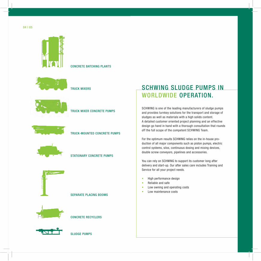
SCHWING is one of the leading manufacturers of sludge pumps and provides turnkey solutions for the transport and storage of sludges as well as materials with a high solids content.A detailed customer oriented project planning and an effective design go hand in hand with a thorough consultation that rounds off the full scope of the competent SCHWING Team.
For the optimum results SCHWING relies on the in-house pro-duction of all major components such as piston pumps, electric control systems, silos, continuous dosing and mixing devices, double screw conveyors, pipelines and accessories.
You can rely on SCHWING to support its customer long after delivery and start-up. Our after sales care includes Training and Service for all your project needs.
• High performance design• Reliable and safe • Low owning and operating costs • Low maintenance costs
ScHwiNg Sludge PumPS iN wOrldwide OPeratiON.
06 | 07 fieldS Of aPPlicatiON kSP
kSP - fieldS Of aPPlicatiON
waSte water treatmeNt PlaNtS (wwtP)
• Sewage sludge mechanically dewatered and with foreign particles
waSte recycliNg
• Waste sludge• Oil sludge • Salt mud • Radioactive waste • Et al.
cONStructiON iNduStry
• Bentonite • Clay mud • Mortar • Tailings • Et al.
miNiNg | refiNerieS | POwer PlaNtS
• Red mud• Gold slime • Iron sludge• Zinc sludge• Metallic oxide sludge • Fly ash• Et al.
cHemiStry aNd iNduStry
• Organic and inorganic materials• Stabilized chemical waste• Lime slurry • Food-processing by-products• Paint sludges
fOrage iNduStry
• Cattle fodder• Fish waste • Animal carcass by-products• Animal waste
water Sludge remOval
• Dredged material• Water sludge • Silt
PaPer iNduStry
• Paper pulp
cleaNiNg
• Contaminated soil
reSidueS
• Waste water sludge
Sugar iNduStry
• Carbonation sludge
08 | 09 abbreviatiONS exPlaiNed kSP | taP | eHS | Sd
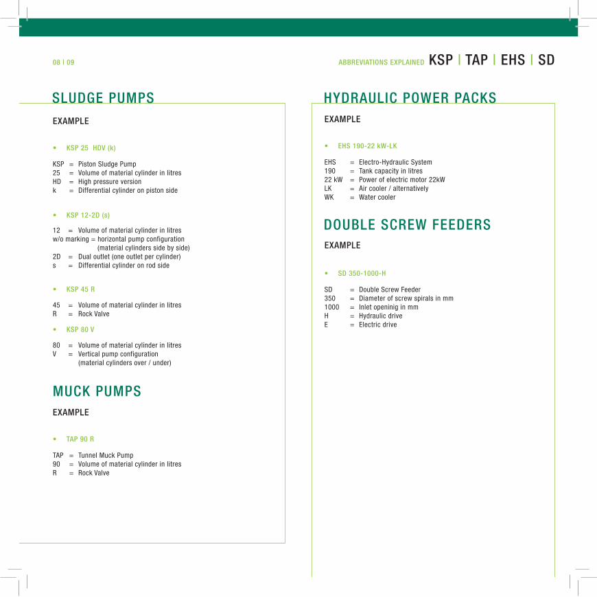
examPle
KSP = Piston Sludge Pump 25 = Volume of material cylinder in litres HD = High pressure versionk = Differential cylinder on piston side
12 = Volume of material cylinder in litres w/o marking = horizontal pump configuration (material cylinders side by side) 2D = Dual outlet (one outlet per cylinder) s = Differential cylinder on rod side
• kSP 25 Hdv (k)
• kSP 12-2d (s)
Hydraulic POwer PackS
dOuble Screw feederS
examPle
examPle
EHS = Electro-Hydraulic System 190 = Tank capacity in litres22 kW = Power of electric motor 22kWLK = Air cooler / alternatively WK = Water cooler
SD = Double Screw Feeder 350 = Diameter of screw spirals in mm 1000 = Inlet openinig in mm H = Hydraulic drive E = Electric drive
45 = Volume of material cylinder in litres R = Rock Valve
80 = Volume of material cylinder in litresV = Vertical pump configuration (material cylinders over / under)
• kSP 45 r
• kSP 80 v
muck PumPSexamPle
TAP = Tunnel Muck Pump90 = Volume of material cylinder in litres R = Rock Valve
• taP 90 r
• eHS 190-22 kw-lk
• Sd 350-1000-H
Sludge PumPS
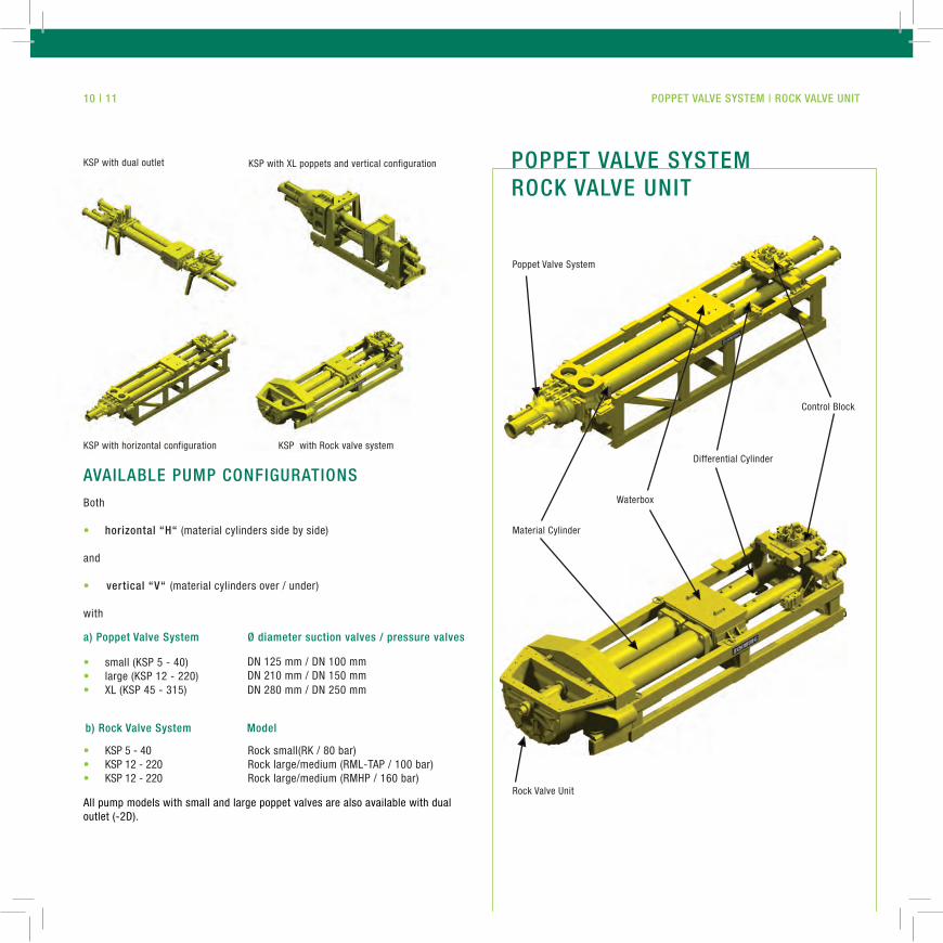
available PumP cONfiguratiONS
Both
• horizontal “H“ (material cylinders side by side)
and
• vertical “v“ (material cylinders over / under)
with
KSP with Rock valve system
KSP with XL poppets and vertical configuration
KSP with horizontal configuration
KSP with dual outlet POPPet valve SyStemrOck valve uNit
Poppet Valve System
Material Cylinder
Waterbox
Differential Cylinder
Control Block
Rock Valve Unit
a) Poppet valve System
• small (KSP 5 - 40)• large (KSP 12 - 220)• XL (KSP 45 - 315)
All pump models with small and large poppet valves are also available with dual outlet (-2D).
DN 125 mm / DN 100 mm DN 210 mm / DN 150 mm DN 280 mm / DN 250 mm
Ø diameter suction valves / pressure valves
b) rock valve System model
• KSP 5 - 40• KSP 12 - 220• KSP 12 - 220
Rock small(RK / 80 bar)Rock large/medium (RML-TAP / 100 bar)Rock large/medium (RMHP / 160 bar)
10 | 11 POPPet valve SyStem | rOck valve uNit
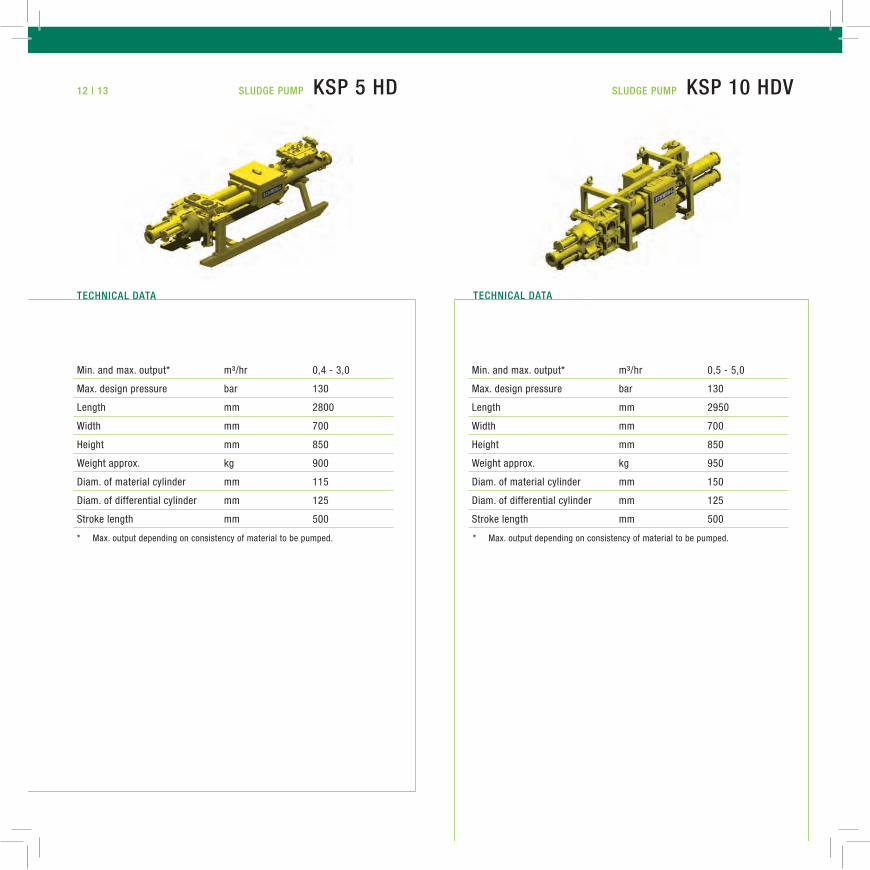
* Max. output depending on consistency of material to be pumped. * Max. output depending on consistency of material to be pumped.
Min. and max. output* m³/hr 0,4 - 3,0
Max. design pressure bar 130
Length mm 2800
Width mm 700
Height mm 850
Weight approx. kg 900
Diam. of material cylinder mm 115
Diam. of differential cylinder mm 125
Stroke length mm 500
Min. and max. output* m³/hr 0,5 - 5,0
Max. design pressure bar 130
Length mm 2950
Width mm 700
Height mm 850
Weight approx. kg 950
Diam. of material cylinder mm 150
Diam. of differential cylinder mm 125
Stroke length mm 500
tecHNical datatecHNical data
12 | 13 Sludge PumP kSP 10 HdvSludge PumP kSP 5 Hd
* Max. output depending on consistency of material to be pumped. * Max. output depending on consistency of material to be pumped.
Min. and max. output* m³/hr 1,5 - 10,0
Max. design pressure bar 130
Length mm 3960
Width mm 700
Height mm 850
Weight approx. kg 1.000
Diam. of material cylinder mm 150
Diam. of differential cylinder mm 125
Stroke length mm 1000
tecHNical datatecHNical data
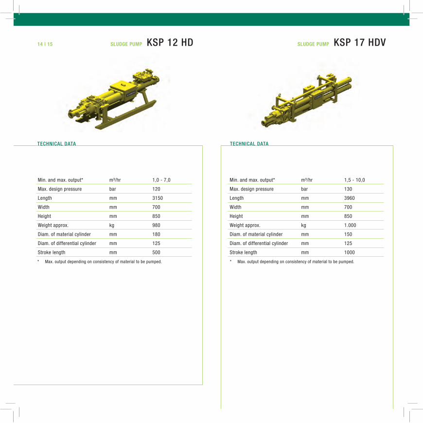
Min. and max. output* m³/hr 1,0 - 7,0
Max. design pressure bar 120
Length mm 3150
Width mm 700
Height mm 850
Weight approx. kg 980
Diam. of material cylinder mm 180
Diam. of differential cylinder mm 125
Stroke length mm 500
14 | 15 Sludge PumP kSP 17 HdvSludge PumP kSP 12 Hd
* Max. output depending on consistency of material to be pumped. * Max. output depending on consistency of material to be pumped.
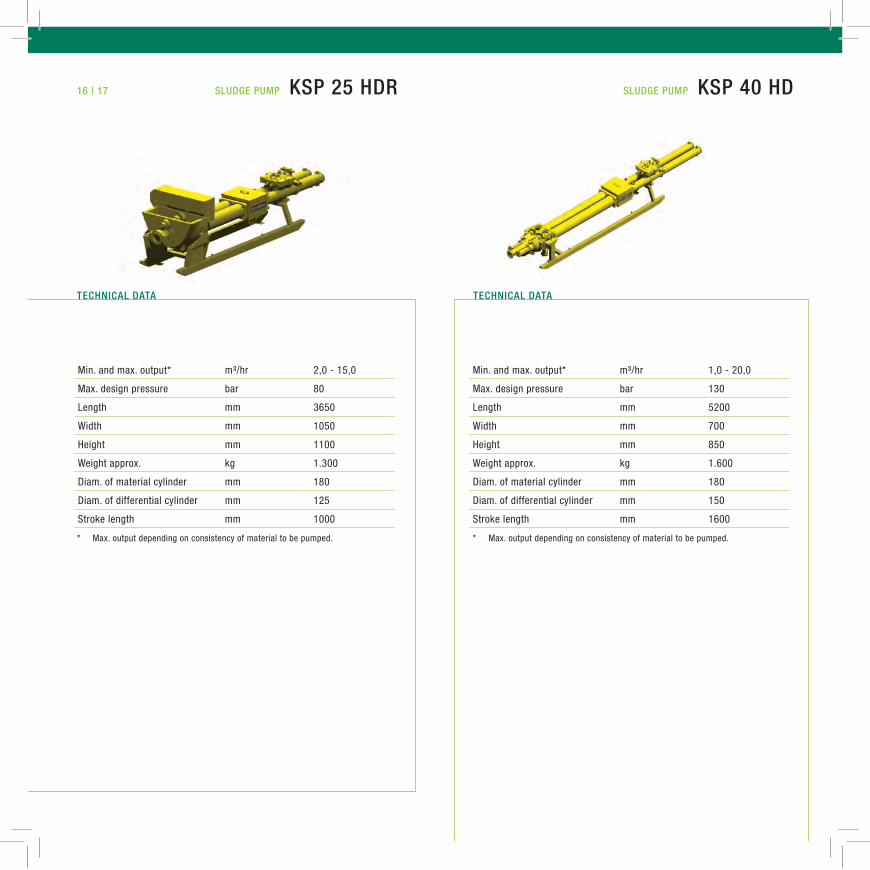
Min. and max. output* m³/hr 2,0 - 15,0
Max. design pressure bar 80
Length mm 3650
Width mm 1050
Height mm 1100
Weight approx. kg 1.300
Diam. of material cylinder mm 180
Diam. of differential cylinder mm 125
Stroke length mm 1000
Min. and max. output* m³/hr 1,0 - 20,0
Max. design pressure bar 130
Length mm 5200
Width mm 700
Height mm 850
Weight approx. kg 1.600
Diam. of material cylinder mm 180
Diam. of differential cylinder mm 150
Stroke length mm 1600
Sludge PumP kSP 40 HdSludge PumP kSP 25 Hdr
tecHNical datatecHNical data
16 | 17
18 | 19
* Max. output depending on consistency of material to be pumped. * Max. output depending on consistency of material to be pumped.
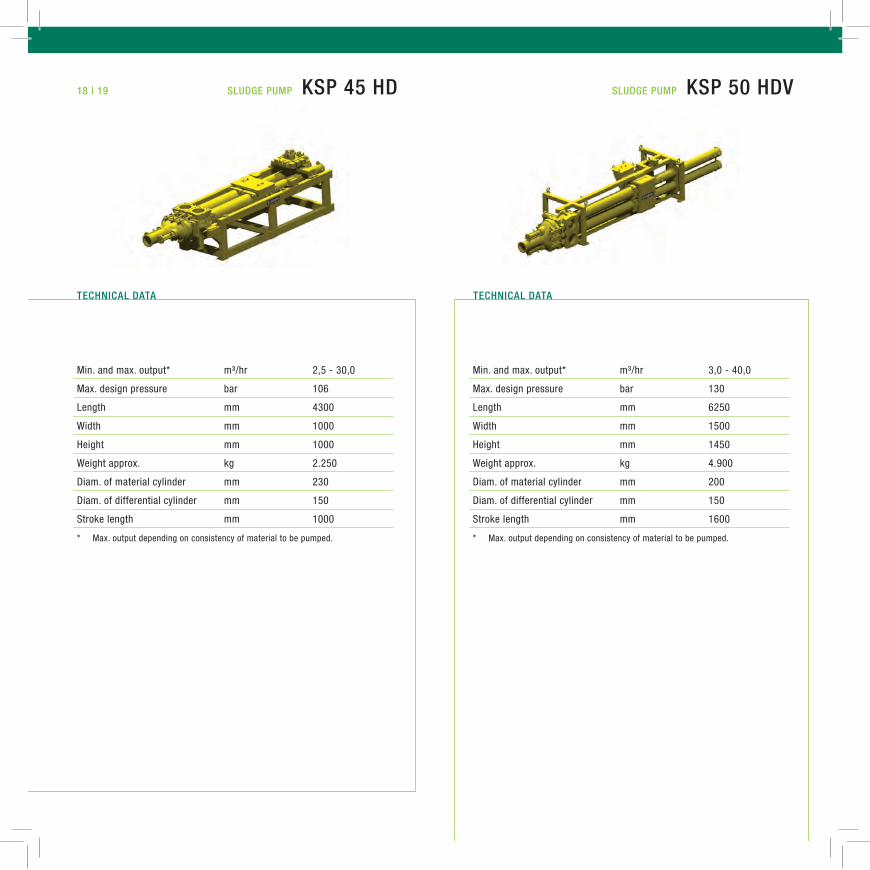
Min. and max. output* m³/hr 2,5 - 30,0
Max. design pressure bar 106
Length mm 4300
Width mm 1000
Height mm 1000
Weight approx. kg 2.250
Diam. of material cylinder mm 230
Diam. of differential cylinder mm 150
Stroke length mm 1000
Min. and max. output* m³/hr 3,0 - 40,0
Max. design pressure bar 130
Length mm 6250
Width mm 1500
Height mm 1450
Weight approx. kg 4.900
Diam. of material cylinder mm 200
Diam. of differential cylinder mm 150
Stroke length mm 1600
Sludge PumP kSP 50 HdvSludge PumP kSP 45 Hd
tecHNical datatecHNical data
20 | 21
* Max. output depending on consistency of material to be pumped. * Max. output depending on consistency of material to be pumped.
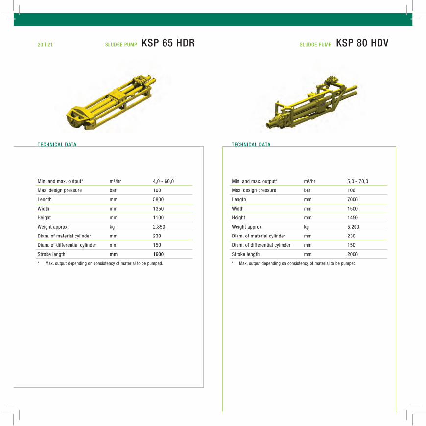
Min. and max. output* m³/hr 4,0 - 60,0
Max. design pressure bar 100
Length mm 5800
Width mm 1350
Height mm 1100
Weight approx. kg 2.850
Diam. of material cylinder mm 230
Diam. of differential cylinder mm 150
Stroke length mm 1600
Min. and max. output* m³/hr 5,0 - 70,0
Max. design pressure bar 106
Length mm 7000
Width mm 1500
Height mm 1450
Weight approx. kg 5.200
Diam. of material cylinder mm 230
Diam. of differential cylinder mm 150
Stroke length mm 2000
Sludge PumP kSP 65 Hdr Sludge PumP kSP 80 Hdv
tecHNical datatecHNical data
22 | 23
* Max. output depending on consistency of material to be pumped. * Max. output depending on consistency of material to be pumped.
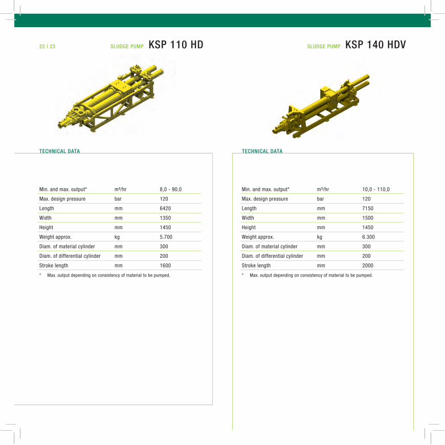
Min. and max. output* m³/hr 10,0 - 110,0
Max. design pressure bar 120
Length mm 7150
Width mm 1500
Height mm 1450
Weight approx. kg 6.300
Diam. of material cylinder mm 300
Diam. of differential cylinder mm 200
Stroke length mm 2000
Sludge PumP kSP 140 Hdv
tecHNical datatecHNical data
Min. and max. output* m³/hr 8,0 - 90,0
Max. design pressure bar 120
Length mm 6420
Width mm 1350
Height mm 1450
Weight approx. kg 5.700
Diam. of material cylinder mm 300
Diam. of differential cylinder mm 200
Stroke length mm 1600
Sludge PumP kSP 110 Hd
24 | 25
* Max. output depending on consistency of material to be pumped. * Max. output depending on consistency of material to be pumped.
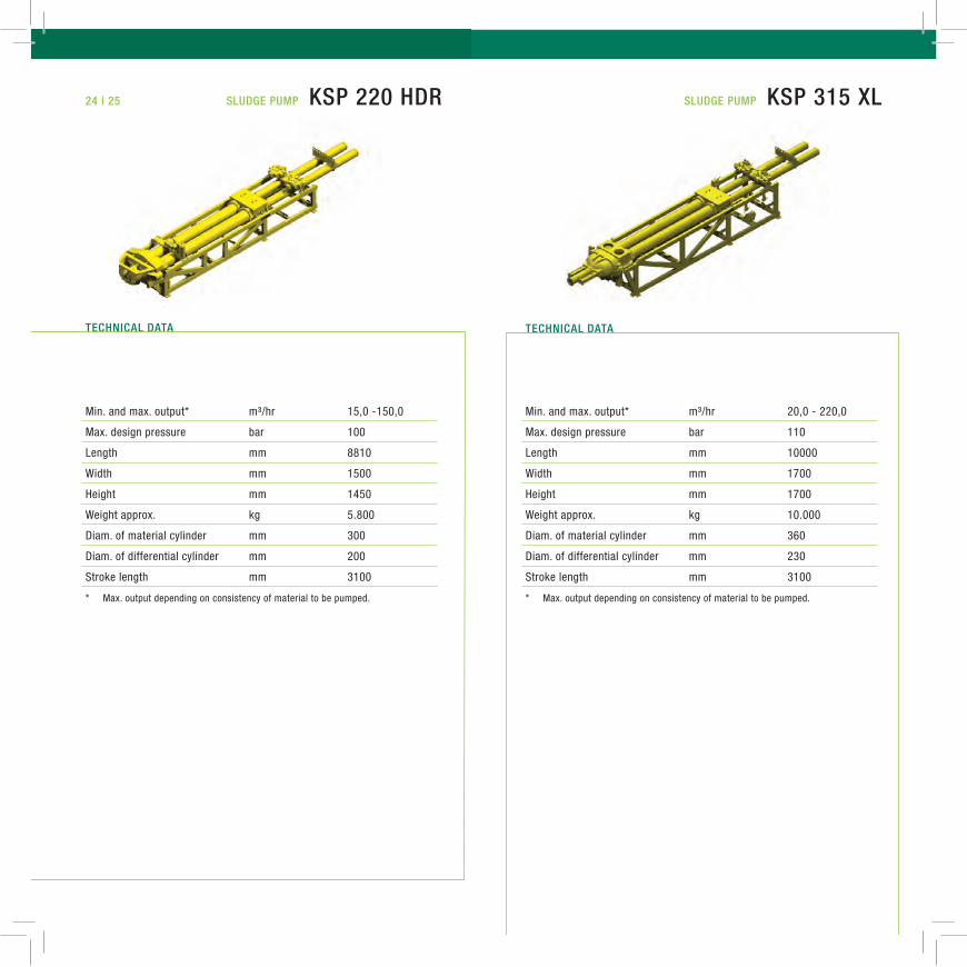
Min. and max. output* m³/hr 20,0 - 220,0
Max. design pressure bar 110
Length mm 10000
Width mm 1700
Height mm 1700
Weight approx. kg 10.000
Diam. of material cylinder mm 360
Diam. of differential cylinder mm 230
Stroke length mm 3100
Sludge PumP kSP 315 xl
tecHNical data tecHNical data
Min. and max. output* m³/hr 15,0 -150,0
Max. design pressure bar 100
Length mm 8810
Width mm 1500
Height mm 1450
Weight approx. kg 5.800
Diam. of material cylinder mm 300
Diam. of differential cylinder mm 200
Stroke length mm 3100
Sludge PumP kSP 220 Hdr
26 | 27
* Max. output depending on consistency of material to be pumped.
* Max. output depending on consistency of material to be pumped. * Max. output depending on consistency of material to be pumped.
* Max. output depending on consistency of material to be pumped.
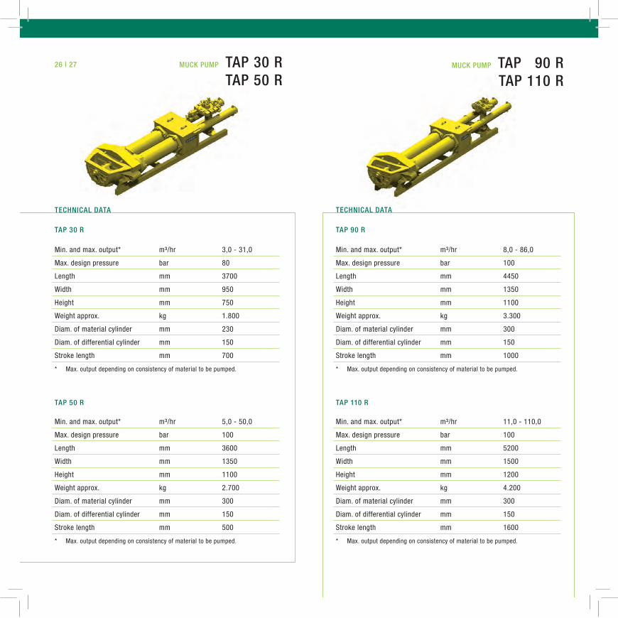
Min. and max. output* m³/hr 3,0 - 31,0
Max. design pressure bar 80
Length mm 3700
Width mm 950
Height mm 750
Weight approx. kg 1.800
Diam. of material cylinder mm 230
Diam. of differential cylinder mm 150
Stroke length mm 700
Min. and max. output* m³/hr 5,0 - 50,0
Max. design pressure bar 100
Length mm 3600
Width mm 1350
Height mm 1100
Weight approx. kg 2.700
Diam. of material cylinder mm 300
Diam. of differential cylinder mm 150
Stroke length mm 500
Min. and max. output* m³/hr 11,0 - 110,0
Max. design pressure bar 100
Length mm 5200
Width mm 1500
Height mm 1200
Weight approx. kg 4.200
Diam. of material cylinder mm 300
Diam. of differential cylinder mm 150
Stroke length mm 1600
Min. and max. output* m³/hr 8,0 - 86,0
Max. design pressure bar 100
Length mm 4450
Width mm 1350
Height mm 1100
Weight approx. kg 3.300
Diam. of material cylinder mm 300
Diam. of differential cylinder mm 150
Stroke length mm 1000
muck PumP taP 90 r taP 110 r
muck PumP taP 30 r taP 50 r
tecHNical datatecHNical data
taP 30 r taP 90 r
taP 50 r taP 110 r
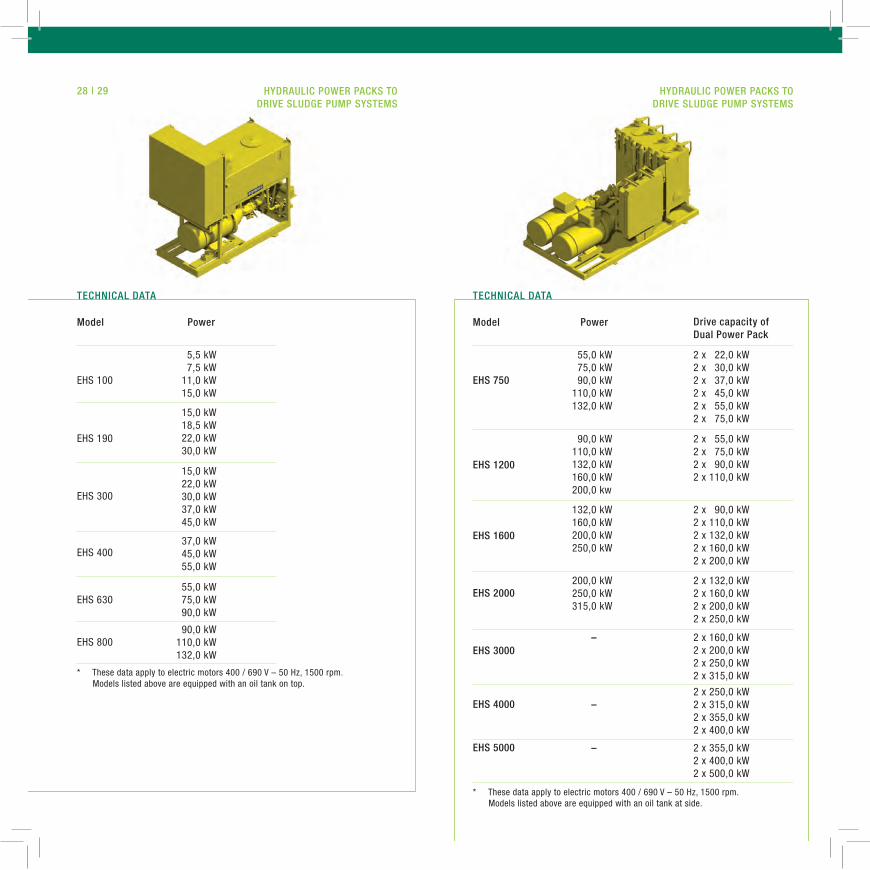
005,5 kW007,5 kW011,0 kW015,0 kW
055,0 kW075,0 kW090,0 kW110,0 kW132,0 kW
2 x 022,0 kW2 x 030,0 kW2 x 037,0 kW2 x 045,0 kW2 x 055,0 kW2 x 075,0 kW
015,0 kW022,0 kW030,0 kW037,0 kW045,0 kW
132,0 kW160,0 kW200,0 kW250,0 kW
2 x 190,0 kW2 x 110,0 kW2 x 132,0 kW2 x 160,0 kW2 x 200,0 kW
055,0 kW075,0 kW090,0 kW
– 2 x 160,0 kW2 x 200,0 kW2 x 250,0 kW2 x 315,0 kW
015,0 kW018,5 kW022,0 kW030,0 kW
090,0 kW110,0 kW132,0 kW160,0 kW200,0 kw
2 x 055,0 kW2 x 075,0 kW2 x 090,0 kW2 x 110,0 kW
037,0 kW045,0 kW055,0 kW
200,0 kW250,0 kW315,0 kW
2 x 132,0 kW2 x 160,0 kW2 x 200,0 kW2 x 250,0 kW
090,0 kW110,0 kW132,0 kW
–2 x 250,0 kW 2 x 315,0 kW 2 x 355,0 kW 2 x 400,0 kW
– 2 x 355,0 kW2 x 400,0 kW2 x 500,0 kW
drive capacity of dual Power Pack
EHS 100 eHS 750
EHS 190
eHS 1200
EHS 300
eHS 1600
EHS 630
eHS 3000
EHS 400
eHS 2000
EHS 800
eHS 4000
eHS 5000
28 | 29
* These data apply to electric motors 400 / 690 V – 50 Hz, 1500 rpm. Models listed above are equipped with an oil tank on top.
* These data apply to electric motors 400 / 690 V – 50 Hz, 1500 rpm. Models listed above are equipped with an oil tank at side.
model Power model Power
Hydraulic POwer PackS tO drive Sludge PumP SyStemS
Hydraulic POwer PackS tO drive Sludge PumP SyStemS
tecHNical datatecHNical data

30 | 31
• all control systems are equipped with programmable logic controllers (PLC)
• switch cabinets in the range from 5,5 kW to 1000 kW according to customers request
• fully automatic control and monitoring of the complete sludge pump system
• full system operation by remote control from customers control centre
• control systems manufactured in accordance with all international standards
• modern automation and visual display systems
• problem-free interface and running system integration
Our service includes consultancy, design, engineering as well as delivery and start-up on site.
electric cONtrOl SyStemS fOr Sludge PumPS
electric cONtrOl SyStemS fOr Sludge PumPS
ScHwiNg SyStem eNgiNeeriNg PrOvideS:
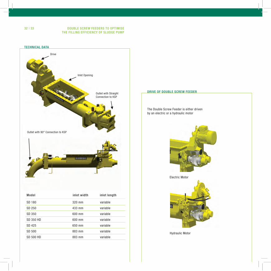
Hydraulic Motor
Electric Motor
The Double Screw Feeder is either driven by an electric or a hydraulic motor
drive Of dOuble Screw feeder
Drive
Inlet Opening
Outlet with Straight Connection to KSP
Outlet with 90° Connection to KSP
tecHNical data
SD 180 320 mm variable
SD 250 433 mm variable
SD 350 600 mm variable
SD 350 HD 600 mm variable
SD 425 650 mm variable
SD 500 883 mm variable
SD 500 HD 883 mm variable
model inlet width inlet length
32 | 33 dOuble Screw feederS tO OPtimiSe tHe filliNg efficieNcy Of Sludge PumP
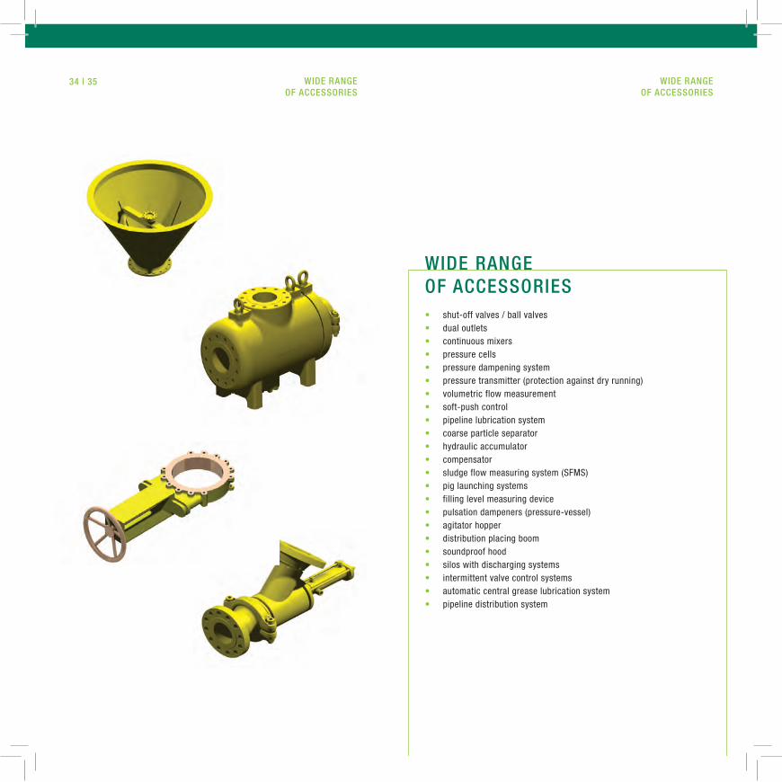
• shut-off valves / ball valves• dual outlets • continuous mixers• pressure cells• pressure dampening system• pressure transmitter (protection against dry running)• volumetric flow measurement• soft-push control• pipeline lubrication system• coarse particle separator• hydraulic accumulator• compensator• sludge flow measuring system (SFMS)• pig launching systems• filling level measuring device• pulsation dampeners (pressure-vessel)• agitator hopper• distribution placing boom• soundproof hood• silos with discharging systems • intermittent valve control systems • automatic central grease lubrication system • pipeline distribution system
wide raNge Of acceSSOrieS
wide raNge Of acceSSOrieS
34 | 35
wide raNge Of acceSSOrieS
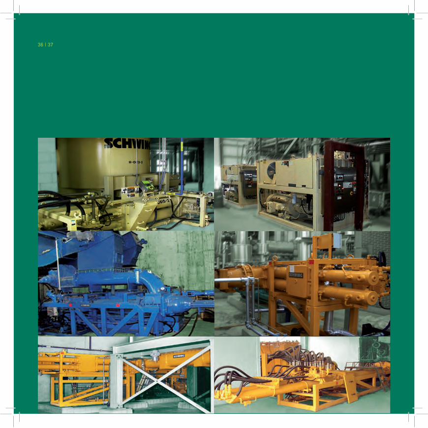
36 | 37
NOteNOte38 | 39

ScHw
iNg
gm
bH |
Hee
rstr
aße
9-2
7 |
d - 4
4653
Her
ne |
t +
4923
25 /
987
-0 |
f +
4923
25 /
72 9
22 |
info
@sc
hwin
g.de
| w
ww
.sch
win
g.de


![[PPT]Determination of the Equilibrium Constant, Ksp, for a ...coolchemistrystuff.yolasite.com/resources/Determine Ksp... · Web viewDetermination of the Equilibrium Constant, Ksp,](https://static.fdocuments.in/doc/165x107/5ae1ff9d7f8b9a595d8ca301/pptdetermination-of-the-equilibrium-constant-ksp-for-a-kspweb-viewdetermination.jpg)