SKIMO SPLIT PLUS - SNDC - SKIMO SPLIT PLUS - ANGLAIS.pdf · SKIMO SPLIT PLUS PART NUMBER : 320B25...
23
Société Nouvelle De Climatisation 274, chemin des Agriés – 31860 LABARTHE SUR LEZE Tél. : 05 34 480 480 - Fax : 05 34 480 481 Ce document est la propriété de SNDC SAS – Il ne peut être ni reproduit, ni communiqué sans autorisation de SNDC SAS. This document is the property of SNDC SAS – It can neither be reproduced, nor communicated without SNDC SAS's written authorization. Version 1 – 24/06/15 810C78-EN-MANUTMAIN EN INSTALLATION, USER AND MAINTENANCE MANUAL SKIMO SPLIT PLUS EN PART NUMBER : 320B25 – SKIMO SPLIT PLUS 24V EN Read this manual carefully until you understand it before unpacking, installing or using the SKIMO unit. Keep this manual for further reference.
-
Upload
duongquynh -
Category
Documents
-
view
230 -
download
3
Transcript of SKIMO SPLIT PLUS - SNDC - SKIMO SPLIT PLUS - ANGLAIS.pdf · SKIMO SPLIT PLUS PART NUMBER : 320B25...
Société Nouvelle De Climatisation
274, chemin des Agriés – 31860 LABARTHE SUR LEZE
Tél. : 05 34 480 480 - Fax : 05 34 480 481
Ce document est la propriété de SNDC SAS – Il ne peut être ni reproduit, ni communiqué sans autorisation de SNDC SAS.
This document is the property of SNDC SAS – It can neither be reproduced, nor communicated without SNDC SAS's written authorization. Version 1 – 24/06/15 810C78-EN-MANUTMAIN
EN INSTALLATION, USER AND MAINTENANCE MANUAL
SKIMO SPLIT PLUS
EN PART NUMBER : 320B25 – SKIMO SPLIT PLUS 24V
EN Read this manual carefully until you understand it before unpacking, installing or using the SKIMO unit.
Keep this manual for further reference.
SKIMO SPLIT PLUS
PART NUMBER : 320B25 (24V)
INSTALLATION, USER AND MAINTENANCE MANUAL
2/23
The 2 years warranty only applies under normal operation of the SKIMO A/C unit. * Limited warranty The warranty doesn’t cover damages resulting from an incorrect operation of the SKIMO A/C unit, particularly for the following cases :
Operating in an environment with high salinity.
Operating in an environment with high acidity.
Cleaning with a pressure washer and/or with detergents.
Consumable parts (filters) or considered as wear parts are also excluded from warranty.
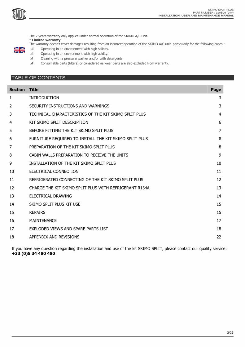
TABLE OF CONTENTS
Section Title Page
1 INTRODUCTION 3
2 SECURITY INSTRUCTIONS AND WARNINGS 3
3 TECHNICAL CHARACTERISTICS OF THE KIT SKIMO SPLIT PLUS 4
4 KIT SKIMO SPLIT DESCRIPTION 6
5 BEFORE FITTING THE KIT SKIMO SPLIT PLUS 7
6 FURNITURE REQUIRED TO INSTALL THE KIT SKIMO SPLIT PLUS 8
7 PREPARATION OF THE KIT SKIMO SPLIT PLUS 8
8 CABIN WALLS PREPARATION TO RECEIVE THE UNITS 9
9 INSTALLATION OF THE KIT SKIMO SPLIT PLUS 10
10 ELECTRICAL CONNECTION 11
11 REFRIGERATED CONNECTING OF THE KIT SKIMO SPLIT PLUS 12
12 CHARGE THE KIT SKIMO SPLIT PLUS WITH REFRIGERANT R134A 13
13 ELECTRICAL DRAWING 14
14 SKIMO SPLIT PLUS KIT USE 15
15 REPAIRS 15
16 MAINTENANCE 17
17 EXPLODED VIEWS AND SPARE PARTS LIST 18
18 APPENDIX AND REVISIONS 22
If you have any question regarding the installation and use of the kit SKIMO SPLIT, please contact our quality service: +33 (0)5 34 480 480

SKIMO SPLIT PLUS
PART NUMBER : 320B25 (24V)
INSTALLATION, USER AND MAINTENANCE MANUAL
3/23
1. INTRODUCTION
The SKIMO SPLIT PLUS KIT described in this manual, is composed of an outside unit SKIMO SPLIT PLUS and an
evaporator unit to be positioned inside the cabin. The compressor - condenser unit can be installed horizontally on a
wall or flat on a hood (see pictures).
The SKIMO SPLIT PLUS KIT is particularly adapted to the compact machines with little room or a small driving power, to
the machines the cabin of which is far from the engine and to the users wishing a fast and easy assembly.
The SKIMO SPLIT PLUS unit has the compressor integrated and driven by an electric motor. 2 units will be linked between them by 2 hoses (high and low pressure) and electrically by a harness.
(See the recommendations on the power supply with the rest of the vehicle). The charge of refrigerant R134a will be made by a qualified and approved technician.
2. SECURITY INSTRUCTIONS AND WARNINGS
You must read and understand this manual before proceeding to the installation, set-up, use and maintenance of the SKIMO SPLIT PLUS KIT.
List of pictograms used in this manual or on the unit:
Pictogram Meaning Pictogram Meaning
Conform to CE standard
General danger
Read and understand the manual
Physical danger
Important information
The SKIMO SPLIT PLUS SKIT must be installed by a person qualified and adequately equipped. All alteration of the
unit or incorrect installation is strictly forbidden and can be dangerous. SNDC SAS cannot be held responsible in the case of physical or material damages due to an alteration, installation or use that is different to that described in this manual
The SKIMO SPLIT PLUS unit weights approximately 30 kg. Take necessary precautions when handling, installing and
using the unit to avoid any risk of injury, fall or damage. Do not handle or install the SKIMO SPLIT PLUS unit on your
own.
Do not store, install or use the SKIMO SPLIT PLUS KIT close to flammable liquids, gas or solids, or close by a heat
source or in a place presenting risks of explosion or fire.
If the SKIMO SPLIT PLUS KIT is damaged, it must not be used or turned on. It must be repaired or replaced first.
If repairs or maintenance operations are required on the SKIMO SPLIT PLUS KIT, use a qualified company using qualified personnel to perform the operations. Any repair or maintenance operation that is not done properly can create
risks of danger. Do not try to repair the SKIMO SPLIT PLUS by your own means if you are not qualified. For the charge or
Wall mounting Flat mounting
ATTENTION TO THE
MOUNTING ORIENTATION!
THE BEVEL SIDE TO THE TOP
SKIMO SPLIT PLUS
PART NUMBER : 320B25 (24V)
INSTALLATION, USER AND MAINTENANCE MANUAL
4/23
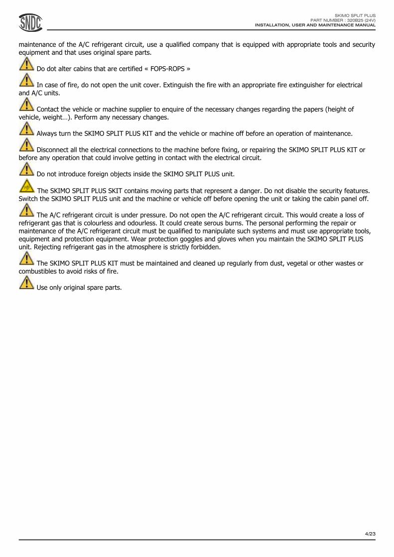
maintenance of the A/C refrigerant circuit, use a qualified company that is equipped with appropriate tools and security equipment and that uses original spare parts.
Do dot alter cabins that are certified « FOPS-ROPS »
In case of fire, do not open the unit cover. Extinguish the fire with an appropriate fire extinguisher for electrical
and A/C units.
Contact the vehicle or machine supplier to enquire of the necessary changes regarding the papers (height of vehicle, weight…). Perform any necessary changes.
Always turn the SKIMO SPLIT PLUS KIT and the vehicle or machine off before an operation of maintenance.
Disconnect all the electrical connections to the machine before fixing, or repairing the SKIMO SPLIT PLUS KIT or before any operation that could involve getting in contact with the electrical circuit.
Do not introduce foreign objects inside the SKIMO SPLIT PLUS unit.
The SKIMO SPLIT PLUS SKIT contains moving parts that represent a danger. Do not disable the security features. Switch the SKIMO SPLIT PLUS unit and the machine or vehicle off before opening the unit or taking the cabin panel off.
The A/C refrigerant circuit is under pressure. Do not open the A/C refrigerant circuit. This would create a loss of
refrigerant gas that is colourless and odourless. It could create serous burns. The personal performing the repair or maintenance of the A/C refrigerant circuit must be qualified to manipulate such systems and must use appropriate tools,
equipment and protection equipment. Wear protection goggles and gloves when you maintain the SKIMO SPLIT PLUS unit. Rejecting refrigerant gas in the atmosphere is strictly forbidden.
The SKIMO SPLIT PLUS KIT must be maintained and cleaned up regularly from dust, vegetal or other wastes or
combustibles to avoid risks of fire.
Use only original spare parts.
SKIMO SPLIT PLUS
PART NUMBER : 320B25 (24V)
INSTALLATION, USER AND MAINTENANCE MANUAL
5/23
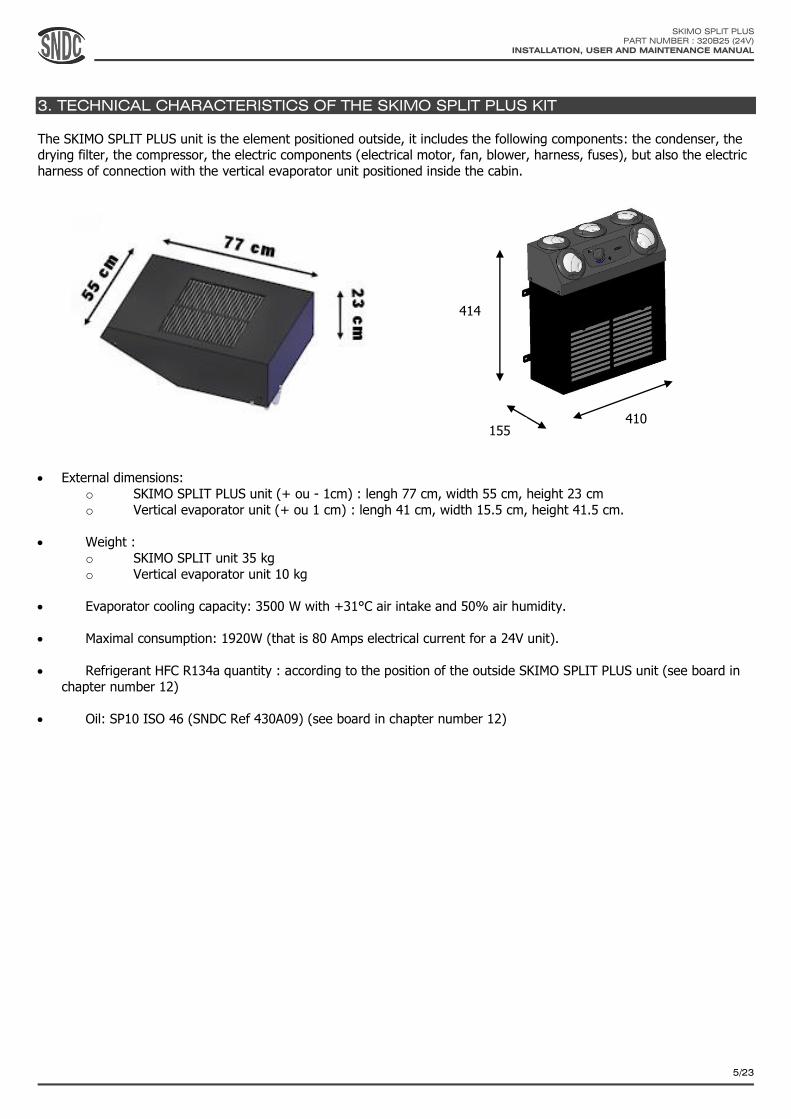
3. TECHNICAL CHARACTERISTICS OF THE SKIMO SPLIT PLUS KIT
The SKIMO SPLIT PLUS unit is the element positioned outside, it includes the following components: the condenser, the drying filter, the compressor, the electric components (electrical motor, fan, blower, harness, fuses), but also the electric
harness of connection with the vertical evaporator unit positioned inside the cabin.
External dimensions:
o SKIMO SPLIT PLUS unit (+ ou - 1cm) : lengh 77 cm, width 55 cm, height 23 cm
o Vertical evaporator unit (+ ou 1 cm) : lengh 41 cm, width 15.5 cm, height 41.5 cm.
Weight :
o SKIMO SPLIT unit 35 kg
o Vertical evaporator unit 10 kg
Evaporator cooling capacity: 3500 W with +31°C air intake and 50% air humidity.
Maximal consumption: 1920W (that is 80 Amps electrical current for a 24V unit).
Refrigerant HFC R134a quantity : according to the position of the outside SKIMO SPLIT PLUS unit (see board in
chapter number 12)
Oil: SP10 ISO 46 (SNDC Ref 430A09) (see board in chapter number 12)
414
155 410

SKIMO SPLIT PLUS
PART NUMBER : 320B25 (24V)
INSTALLATION, USER AND MAINTENANCE MANUAL
6/23
4. SKIMO SPLIT PLUS KIT
DESCRIPTION
N° DESCRIPTION
1. Condenser fan
2. SKIMO SPLIT cover
3. External air intake grids
4. Drying filter
5. SKIMO SPLIT PLUS casing
6. M8 unit fastening screws (4)
7. Seal box of fuses and relays
8. Electric motor
9. Compressor
10. LOW-PRESSURE gas connection
11. HIGH-PRESSURE gas connection
12. Electrical harness
13. Control and air distribution plenum
14. Control panel
15. Air filter access grid
16. Grid fastening screws
17. Vertical evaporator unit fixations
18. Adjustable air louvers
19. Default signal light
20. A/C and ventilation speed selector switch
15
16
17
1
2
3
6 4
5
7
8
9
10 11 12
13
14 18
19
20

SKIMO SPLIT PLUS
PART NUMBER : 320B25 (24V)
INSTALLATION, USER AND MAINTENANCE MANUAL
7/23
5. BEFORE FITTING THE SKIMO SPLIT PLUS KIT
Prior to fitting and using the SKIMO SPLIT PLUS KIT, check the following points:
Cabin volume: Ideally the volume of the cabin is approximately 3m3 but if it is over 4m3 the performances of the SKIMO
SPLIT PLUS system will decrease.
Cabin insulation: The cabin walls must be properly insulated, especially from important heat sources (engine, exhaust pipe, hydraulic system …). SNDC SAS cannot be held responsible in the case of poor performances of the SKIMO SPLIT
PLUS system caused by poor cabin insulation.
Electrical power: The machine or vehicle engine must be equipped with an alternator able to supply the electrical power required from the vehicle or machine AND from the KIT SKIMO SPLIT PLUS. The SKIMO SPLIT PLUS system maximal consumption is 1920W (80 Amps for a 24V unit). If the vehicle or the machine is equipped with an alternator that is not powerful enough, it must be replaced by a suitable alternator.
Roof and ceiling: Do not alter or make a hole in the cabin of vehicles that are certified « FOPS-ROPS » The walll must be stiff and strong enough for the Skimo SPLIT PLUS unit to be installed on. If it is not the case, the wall must be reinforced. The SKIMO SPLIT PLUS unit must not be installed if it would affect the stability of the vehicle or machine it is installed on, or if it would create excessive strains on its structure. Make sure using the drawing showing the dimensions of the unit and the cut-out area that there is enough space to fit the unit outside on the wall and the vertical evaporator unit n panel inside the cabin. The surface on which unit is installed must be flat and horizontal (+/- 5°). The cabin panel must be installed inside the cabin, and the user must be able to access the controls from his driving position while using the vehicle or machine.
SKIMO SPLIT PLUS
PART NUMBER : 320B25 (24V)
INSTALLATION, USER AND MAINTENANCE MANUAL
8/23
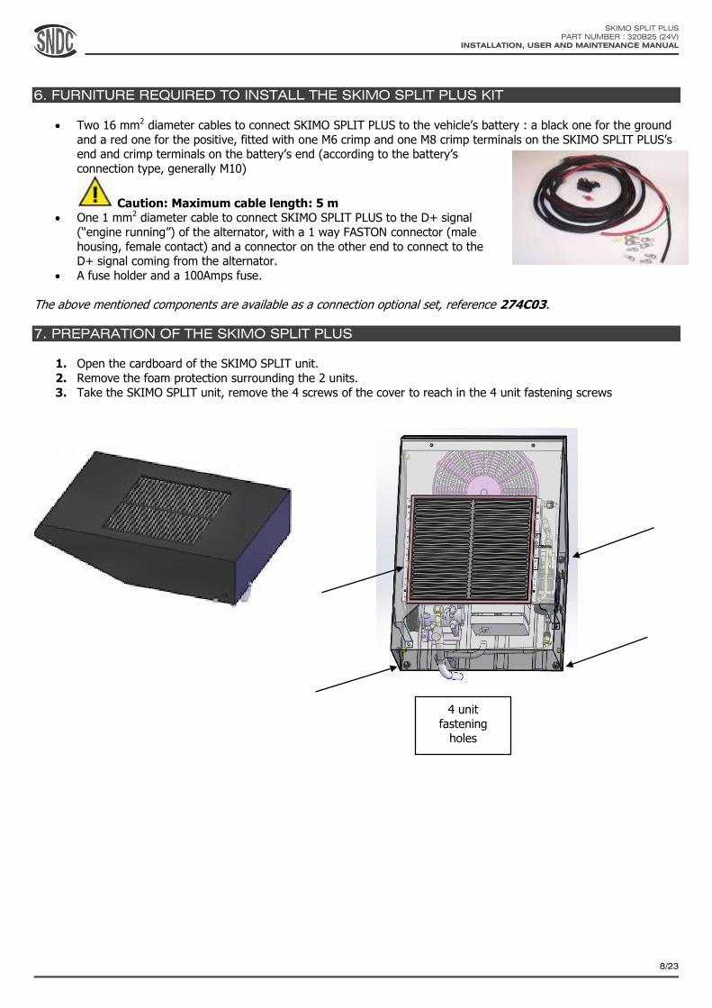
6. FURNITURE REQUIRED TO INSTALL THE SKIMO SPLIT PLUS KIT
Two 16 mm2 diameter cables to connect SKIMO SPLIT PLUS to the vehicle’s battery : a black one for the ground
and a red one for the positive, fitted with one M6 crimp and one M8 crimp terminals on the SKIMO SPLIT PLUS’s end and crimp terminals on the battery’s end (according to the battery’s
connection type, generally M10)
Caution: Maximum cable length: 5 m One 1 mm2 diameter cable to connect SKIMO SPLIT PLUS to the D+ signal
(“engine running”) of the alternator, with a 1 way FASTON connector (male
housing, female contact) and a connector on the other end to connect to the D+ signal coming from the alternator.
A fuse holder and a 100Amps fuse.
The above mentioned components are available as a connection optional set, reference 274C03.
7. PREPARATION OF THE SKIMO SPLIT PLUS
1. Open the cardboard of the SKIMO SPLIT unit.
2. Remove the foam protection surrounding the 2 units.
3. Take the SKIMO SPLIT unit, remove the 4 screws of the cover to reach in the 4 unit fastening screws
4 unit fastening
holes
SKIMO SPLIT PLUS
PART NUMBER : 320B25 (24V)
INSTALLATION, USER AND MAINTENANCE MANUAL
9/23
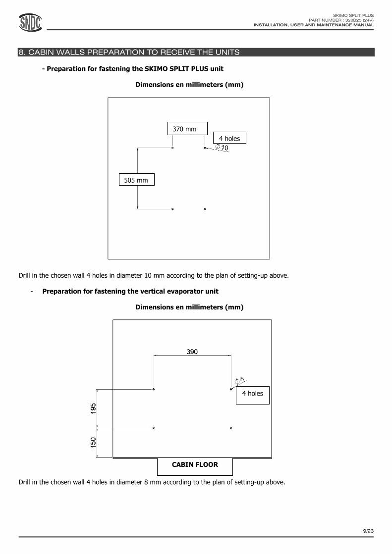
8. CABIN WALLS PREPARATION TO RECEIVE THE UNITS
- Preparation for fastening the SKIMO SPLIT PLUS unit
Dimensions en millimeters (mm)
Drill in the chosen wall 4 holes in diameter 10 mm according to the plan of setting-up above.
- Preparation for fastening the vertical evaporator unit
Dimensions en millimeters (mm)
Drill in the chosen wall 4 holes in diameter 8 mm according to the plan of setting-up above.
4 holes
4 holes
CABIN FLOOR
370 mm
505 mm
SKIMO SPLIT PLUS
PART NUMBER : 320B25 (24V)
INSTALLATION, USER AND MAINTENANCE MANUAL
10/23
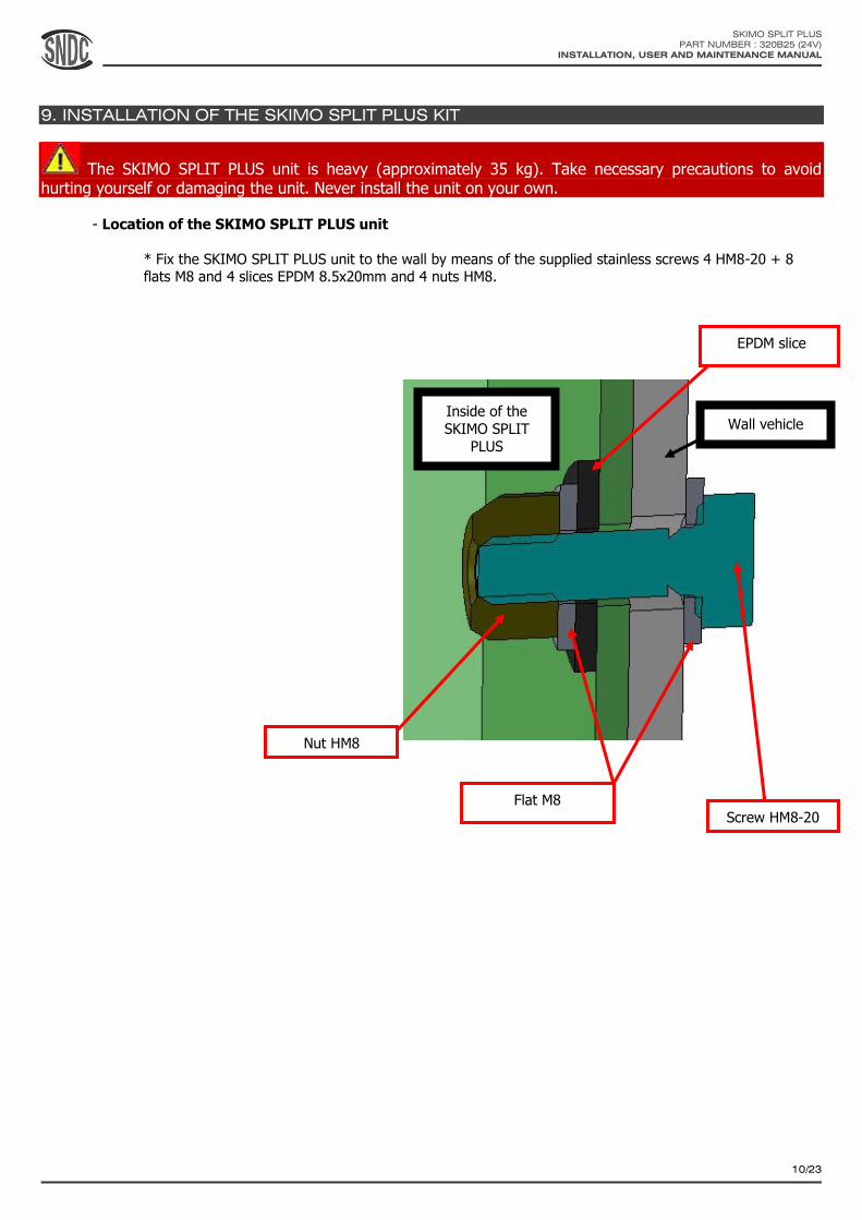
9. INSTALLATION OF THE SKIMO SPLIT PLUS KIT
The SKIMO SPLIT PLUS unit is heavy (approximately 35 kg). Take necessary precautions to avoid hurting yourself or damaging the unit. Never install the unit on your own.
- Location of the SKIMO SPLIT PLUS unit
* Fix the SKIMO SPLIT PLUS unit to the wall by means of the supplied stainless screws 4 HM8-20 + 8 flats M8 and 4 slices EPDM 8.5x20mm and 4 nuts HM8.
Nut HM8
Flat M8 Screw HM8-20
EPDM slice
Inside of the
SKIMO SPLIT
PLUS
Wall vehicle

SKIMO SPLIT PLUS
PART NUMBER : 320B25 (24V)
INSTALLATION, USER AND MAINTENANCE MANUAL
11/23
Location of the vertical evaporator unit
Fix the vertical evaporator unit to the wall by means of the supplied stainless screws 4 HM6-25 + 8 flats M6 and 4 nuts
HM6.
Inside the cabin
SKIMO SPLIT PLUS
PART NUMBER : 320B25 (24V)
INSTALLATION, USER AND MAINTENANCE MANUAL
12/23
10. ELECTRICAL CONNECTION
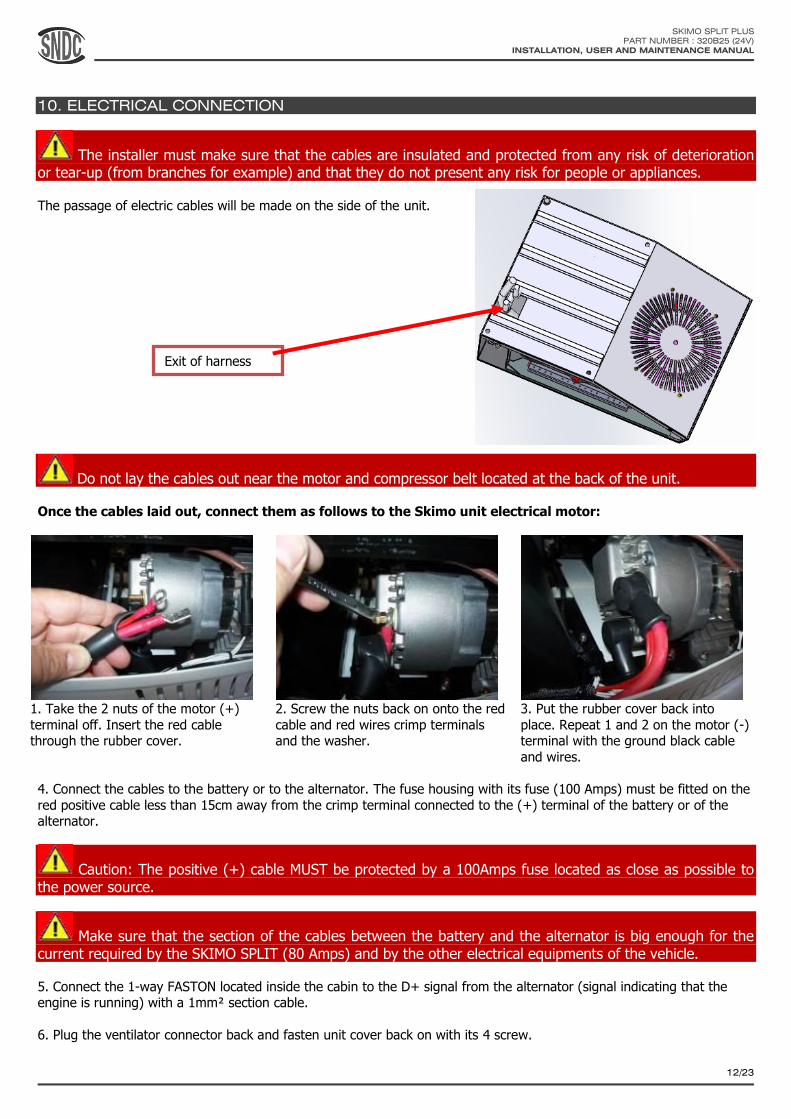
The installer must make sure that the cables are insulated and protected from any risk of deterioration or tear-up (from branches for example) and that they do not present any risk for people or appliances.
The passage of electric cables will be made on the side of the unit.
Do not lay the cables out near the motor and compressor belt located at the back of the unit.
Once the cables laid out, connect them as follows to the Skimo unit electrical motor:
1. Take the 2 nuts of the motor (+)
terminal off. Insert the red cable through the rubber cover.
2. Screw the nuts back on onto the red
cable and red wires crimp terminals and the washer.
3. Put the rubber cover back into
place. Repeat 1 and 2 on the motor (-) terminal with the ground black cable
and wires.
4. Connect the cables to the battery or to the alternator. The fuse housing with its fuse (100 Amps) must be fitted on the
red positive cable less than 15cm away from the crimp terminal connected to the (+) terminal of the battery or of the alternator.
Caution: The positive (+) cable MUST be protected by a 100Amps fuse located as close as possible to the power source.
Make sure that the section of the cables between the battery and the alternator is big enough for the current required by the SKIMO SPLIT (80 Amps) and by the other electrical equipments of the vehicle.
5. Connect the 1-way FASTON located inside the cabin to the D+ signal from the alternator (signal indicating that the engine is running) with a 1mm² section cable.
6. Plug the ventilator connector back and fasten unit cover back on with its 4 screw.
Exit of harness

SKIMO SPLIT PLUS
PART NUMBER : 320B25 (24V)
INSTALLATION, USER AND MAINTENANCE MANUAL
13/23
11. REFRIGERATED CONNECTING OF THE SKIMO SPLIT PLUS KIT
Connect the SKIMO SPLIT PLUS unit and the vertical evaporator unit by 2 hoses with oring steel fittings to be determined by the customer:
- A flexible hose M6, high pressure, connecting the entrance of the evaporator unit to the entrance of the SKIMO SPLIT PLUS unit.
- A flexible hose M10, low pressure, connecting the exit of the SKIMO SPLIT PLUS unit with the exit of the vertical evaporator unit.
Lubrificate lightly each Oring with the same oil SP10 or PAG 46 than for the compressor before connecting any fitting. Make sure the hoses be correctly connected, so as not to be in contact with cutting parts or heat source. When flexible hoses cross a wall, it’s necessary to use one thread rubber or adapted protective plastic ducts.
240A31
240A11
241A41
241A39 241A41
241A37
241A35 241A41
SKIMO SPLIT PLUS
PART NUMBER : 320B25 (24V)
INSTALLATION, USER AND MAINTENANCE MANUAL
14/23
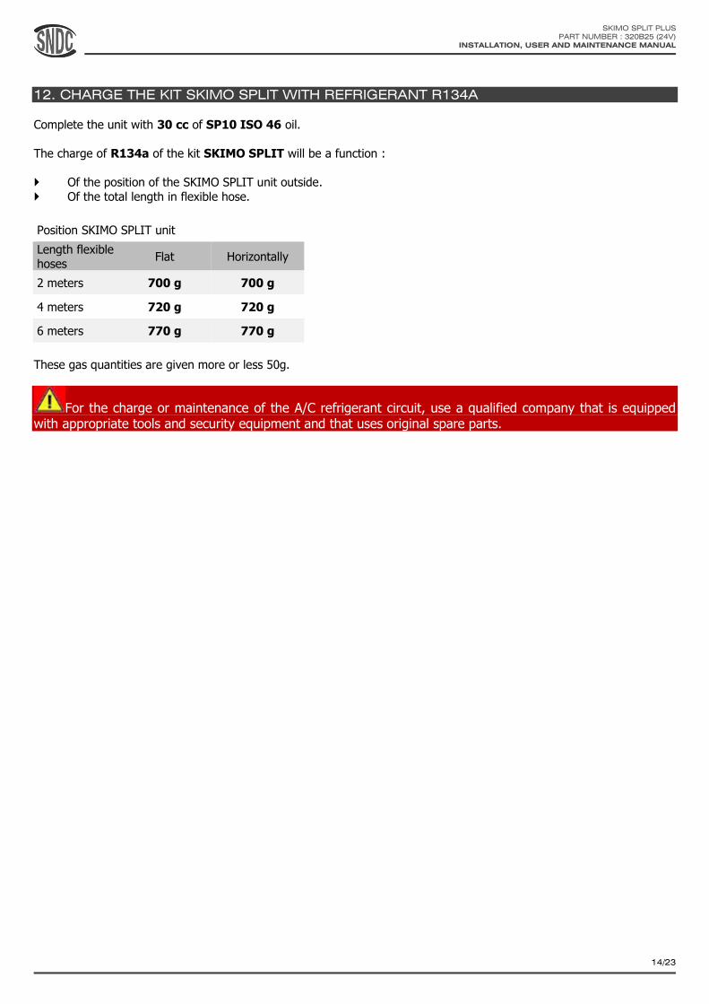
12. CHARGE THE KIT SKIMO SPLIT WITH REFRIGERANT R134A
Complete the unit with 30 cc of SP10 ISO 46 oil.
The charge of R134a of the kit SKIMO SPLIT will be a function :
Of the position of the SKIMO SPLIT unit outside.
Of the total length in flexible hose.
Position SKIMO SPLIT unit
Length flexible hoses
Flat Horizontally
2 meters 700 g 700 g
4 meters 720 g 720 g
6 meters 770 g 770 g
These gas quantities are given more or less 50g.
For the charge or maintenance of the A/C refrigerant circuit, use a qualified company that is equipped with appropriate tools and security equipment and that uses original spare parts.
SKIMO SPLIT PLUS
PART NUMBER : 320B25 (24V)
INSTALLATION, USER AND MAINTENANCE MANUAL
15/23
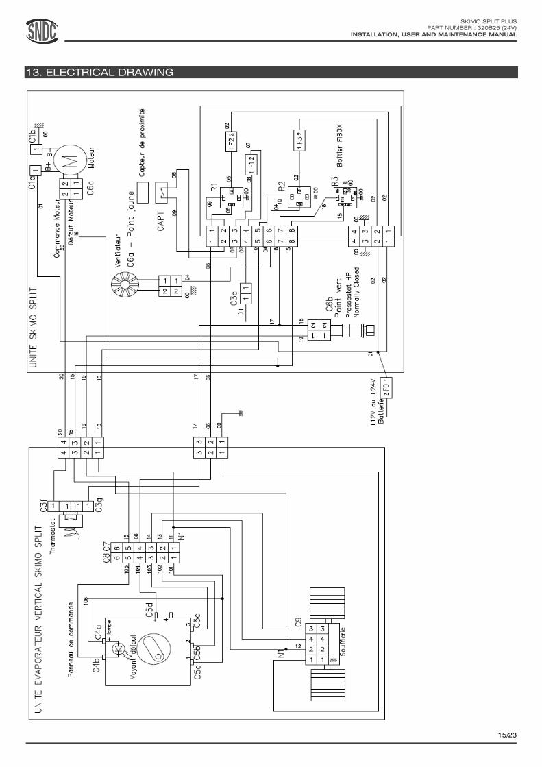
13. ELECTRICAL DRAWING
SKIMO SPLIT PLUS
PART NUMBER : 320B25 (24V)
INSTALLATION, USER AND MAINTENANCE MANUAL
16/23
14. SKIMO SPLIT PLUS KIT USE
The SKIMO SPLIT PLUS KIT is designed to run when the vehicle’s engine is running. If the unit is turned on while the vehicle’s engine is off, the alternator will not feed the unit and there is a risk of battery discharge.
The ability of the SKIMO SPLIT PLUS to maintain the required temperature inside the cabin depends on the amount of heat that penetrates inside the cabin. Some preventive measures are necessary to lower the amount of heat that
enters the cabin and to improve the performances of A/C system: - Park the machine or the vehicle in the shade.
- Drive for a few minutes with the windows opened to lower the temperature inside the cabin before turning the
A/C unit on. - Keep the doors and windows closed while using the A/C unit.
- Avoid using devices that produce heat.
Operating modes:
- Once the SKIMO SPLIT PLUS KIT is installed and the vehicle’s engine is running, turn the control panel ventilation speed
selector switch to first speed to turn the unit on. The first ventilation speed and the air conditioning are turned on. - Adjust the ventilation speed to 1, 2 or 3 according to your requirement with the ventilation speed selector switch.
- To switch the unit off, turn the ventilation speed selector switch to 0.
Switch the SKIMO SPLIT PLUS KIT off if the vehicle’s or machine’s engine runs on low speed for an extended
amount of time (for over 15 minutes). If not, there is a potential risk of battery discharge due to the fact that the alternator might not supply enough power when the engine runs at low speed. The SKIMO SPLIT PLUS unit would turn to
security mode. If that happens, refer to section 15.
It is normal for the internal thermostat to regulate the A/C unit if the blowing temperature is too low, in which case the blowers still run but the air conditioning is turned off for a while.
SNDC SAS cannot be held responsible for condensation appearing on the cabin’s surfaces. The air contains moisture
that tends to condensates on cold surfaces. Appropriate cabin insulation can prevent or lover the risks of condensation.
15. REPAIRS
If the A/C circuit hasn’t got the correct amount of gas, the performances of the A/C system will lower. If it seems
that your SKIMO SPLIT PLUS unit doesn’t work properly, you should take it to an A/C specialist.
Never try to repair faults by your own means. Repair and recharge of an A/C circuit must be carried out by a specialist that is qualified, certified, equipped with necessary tools and that will use original spare parts.
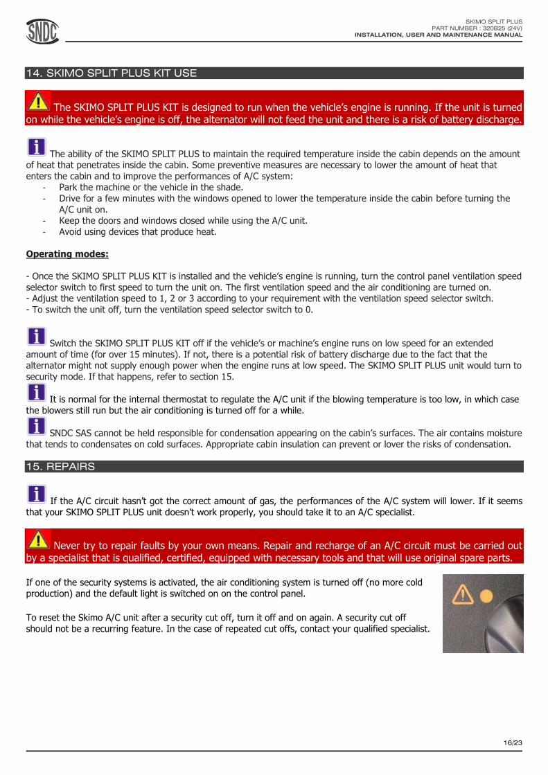
If one of the security systems is activated, the air conditioning system is turned off (no more cold
production) and the default light is switched on on the control panel.
To reset the Skimo A/C unit after a security cut off, turn it off and on again. A security cut off
should not be a recurring feature. In the case of repeated cut offs, contact your qualified specialist.
Révis
ion D

SKIMO SPLIT PLUS
PART NUMBER : 320B25 (24V)
INSTALLATION, USER AND MAINTENANCE MANUAL
17/23
Error codes:
Error code Failure Repair required
1 blink
Overheating of the electrical motor. The temperature of the motor went over 113°C.
The unit can be reset by switching it off and
on again only once the motor’s temperature is lower than 109°C
Check that the air way cooling the electrical motor is not clogged up.
To be done by an A/C specialist:
Check that the A/C circuit hasn’t got too much gas R134a.
2 blink The battery is flat. The tension of the battery went lower than 14V (for a 24V unit)
Check that the battery gets charged up properly and
that the alternator is powerful enough. Check that the vehicle’s engine doesn’t run at low speed for
extended periods of time (over 15 minutes)
3 blink Over consumption of the electrical motor
Check the power consumption of the SKIMO SPLIT PLUS.
To be done by an A/C specialist: Check that the A/C circuit hasn’t got too much
gas R134a.
6 blink Low voltage. The tension of the battery went
lower than 20V (for a 24V unit).
Check that the battery gets charged up properly and that the alternator is powerful enough. Check that
the vehicle’s engine doesn’t run at low speed for extended periods of time (over 15 minutes)
Light on
continuously
A/C system gas low pressure. The pressure
switch is activated for a pressure lower than 2 bars in the high pressure part of the circuit
in case of the quantity of gas being too low (caused by a leak for example).
To be done by an A/C specialist: Check the airtightness of the A/C circuit and
recharge with R134a gas.
Light AND electrical motor
on and off
A/C system gas high pressure. The pressure
switch is activated for a pressure higher than 14 bars in the high pressure part of the
circuit.
Check that the condenser is not clogged up.
To be done by an A/C specialist: Check that the A/C circuit hasn’t got too much
gas R134a.
Light not on
but unit not working
The Skimo A/C is not working properly but
the default light is not switched on. This can be due to an electrical problem.
Check that the default LED light works properly. Check the fuses, the relays, the electrical harness,
the connectors and the electrical connection between the Skimo unit and the vehicle or the
machine.
There are two other security systems on the SKIMO SPLIT PLUS KIT:
Compressor security: The compressor is equipped with a security pressure valve to protect the system in case of a pressure switch failure. Machine security: The SKIMO SPLIT PLUS unit is equipped with a sensor that disables the SKIMO SPLIT PLUS unit if the
cover is opened.
Use only original spare parts.
SKIMO SPLIT PLUS
PART NUMBER : 320B25 (24V)
INSTALLATION, USER AND MAINTENANCE MANUAL
18/23
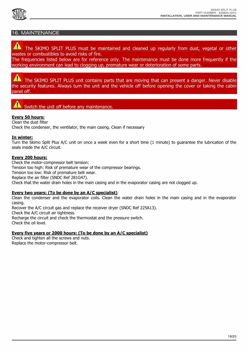
16. MAINTENANCE
The SKIMO SPLIT PLUS must be maintained and cleaned up regularly from dust, vegetal or other wastes or combustibles to avoid risks of fire. The frequencies listed below are for reference only. The maintenance must be done more frequently if the working environment can lead to clogging up, premature wear or deterioration of some parts.
The SKIMO SPLIT PLUS unit contains parts that are moving that can present a danger. Never disable the security features. Always turn the unit and the vehicle off before opening the cover or taking the cabin panel off.
Switch the unit off before any maintenance. Every 50 hours:
Clean the dust filter
Check the condenser, the ventilator, the main casing. Clean if necessary
In winter: Turn the Skimo Split Plus A/C unit on once a week even for a short time (1 minute) to guarantee the lubrication of the
seals inside the A/C circuit.
Every 200 hours:
Check the motor-compressor belt tension: Tension too high: Risk of premature wear of the compressor bearings.
Tension too low: Risk of premature belt wear. Replace the air filter (SNDC Ref 281G47).
Check that the water drain holes in the main casing and in the evaporator casing are not clogged up.
Every two years: (To be done by an A/C specialist)
Clean the condenser and the evaporator coils. Clean the water drain holes in the main casing and in the evaporator casing.
Recover the A/C circuit gas and replace the receiver dryer (SNDC Ref 225A13).
Check the A/C circuit air tightness. Recharge the circuit and check the thermostat and the pressure switch.
Check the oil level.
Every five years or 2000 hours: (To be done by an A/C specialist) Check and tighten all the screws and nuts.
Replace the motor-compressor belt.

SKIMO SPLIT PLUS
PART NUMBER : 320B25 (24V)
INSTALLATION, USER AND MAINTENANCE MANUAL
19/23
17. EXPLODED VIEWS AND SPARE PARTS LIST
SKIMO SPLIT PLUS unit

SKIMO SPLIT PLUS
PART NUMBER : 320B25 (24V)
INSTALLATION, USER AND MAINTENANCE MANUAL
20/23
Repère Référence Description Qté
1 520C29 Unit cover 1
2 560C38 Condenser plate bracket 1
3 296A34 Condenser 1
4 260A23 Fan 24 Volts Ø330 mm blowing 1
5 540F78 560C35
Motor SKIMO 24V 1 KW + motor pulley 1
6 219B87 Belt 4PK0655 1
7 200H05 Compressor PV5 1
8 242C48 Original gas connection 1
9 235I42 M6 Cond/Deshy Hose 1
10 560C36 Rigid line M8 Comp/Cond SPLIT 1
11 225A13 Deshy Alfa 164 1
12 264A40 Binary pressure switch 1
13 226A13 Drying filter bracket 1
14 560C39 Compressor bracket 1
15 560C16 Motor bracket 1
16 273D14 273D15
Safety magnet 1
17 274C51 Box electrical harness 1
18 560C37 Chassis 1
NR 274B71 SKIMO SPLIT PLUS Electrical harness 1

SKIMO SPLIT PLUS
PART NUMBER : 320B25 (24V)
INSTALLATION, USER AND MAINTENANCE MANUAL
21/23
Vertical evaporator unit

SKIMO SPLIT PLUS
PART NUMBER : 320B25 (24V)
INSTALLATION, USER AND MAINTENANCE MANUAL
22/23
Item 24 volts Description Qty
1 530C44 Casing 1
2 530C45 Plenum 1
3 530C47 Bracket blower 1
4 530C46 Air filter access grid 1
5 261A26 Blower 1
6 294C07 Evaporator 1
7 530C48 A/C pipe #6 1
8 250A16 Expansion valve 1
9 350C44 370B32
Adjustable air louvers 5
10 370D43 Control panel adhesive 1
11 265A37 Thermostat 1
12 370D44 Control panel 1
13 234A18 Grommet 35mm 1
14 690A47 Specific screw M4-15 1
15 650A07 Flat washer stainless M22 1
16 243A06 Nut A/C pipe #10 1
17 650A16 Flat washer stainless M16 1
18 640A17 Grower washer stainless M16 1
19 660A20 Nut A/C pipe #6 1
20 281G47 Air filter 1
21 274B70 Electrical harness 1
22 281K41 Back wall insulation 1
23 281K42 Side wall insulation 1
24 281K43 Front wall insulation 1
25 281B80 Conector DEUTSCH gasket 1
26 281A24 Wall fitting gasket #10 1
27 281A03 Wall fitting gasket #6 1

SKIMO SPLIT PLUS
PART NUMBER : 320B25 (24V)
INSTALLATION, USER AND MAINTENANCE MANUAL
23/23
18. APPENDIX AND REVISIONS
Revisions:
Version Date Objet
0 March 2014 Creation
1 June 2015 Update of exploded views and type of oil.


![Service Manual - Термотрейдfile.thermotrade.ru/techno/ServiceDanilov/Split, SKY, Multi/Super... · SiE18-201 J Series Service Manual [Applied Models] Super Multi Plus :](https://static.fdocuments.in/doc/165x107/5ad6eb177f8b9a991b8b758d/service-manual-file-sky-multisupersie18-201-j-series.jpg)


