SKC-600DC SLIDING GATE OPENER OWNER’S · PDF fileThe automatic gate opener must be...
22
SKC-600DC SLIDING GATE OPENER OWNER’S MANUAL
Transcript of SKC-600DC SLIDING GATE OPENER OWNER’S · PDF fileThe automatic gate opener must be...

SKC-600DC SLIDING GATE OPENER
OWNER’S MANUAL

©2005
Gatekeeper Ltd.
P.O. Box 752 Laceys Spring, AL 35754
http://www.gatekeeperltd.com
OUTLINE
1. Safety Precautions 2. Features 3. Specifications 4. Necessary Tools 5. Site Preparation 6. Mechanical Installation 7. Electrical Installation 8. Operation 9. Maintenance & Troubleshooting 10. Warranty
©2005
Gatekeeper Ltd.
P.O. Box 752 Laceys Spring, AL 35754
http://www.gatekeeperltd.com
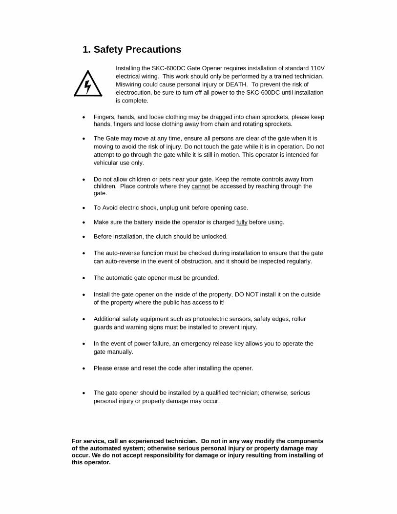
1. Safety Precautions
Installing the SKC-600DC Gate Opener requires installation of standard 110V electrical wiring. This work should only be performed by a trained technician. Miswiring could cause personal injury or DEATH. To prevent the risk of electrocution, be sure to turn off all power to the SKC-600DC until installation is complete.
Fingers, hands, and loose clothing may be dragged into chain sprockets, please keep
hands, fingers and loose clothing away from chain and rotating sprockets.
The Gate may move at any time, ensure all persons are clear of the gate when It is moving to avoid the risk of injury. Do not touch the gate while it is in operation. Do not attempt to go through the gate while it is still in motion. This operator is intended for vehicular use only.
Do not allow children or pets near your gate. Keep the remote controls away from
children. Place controls where they cannot be accessed by reaching through the gate.
To Avoid electric shock, unplug unit before opening case. Make sure the battery inside the operator is charged fully before using. Before installation, the clutch should be unlocked. The auto-reverse function must be checked during installation to ensure that the gate
can auto-reverse in the event of obstruction, and it should be inspected regularly. The automatic gate opener must be grounded. Install the gate opener on the inside of the property, DO NOT install it on the outside
of the property where the public has access to it! Additional safety equipment such as photoelectric sensors, safety edges, roller
guards and warning signs must be installed to prevent injury. In the event of power failure, an emergency release key allows you to operate the
gate manually. Please erase and reset the code after installing the opener.
The gate opener should be installed by a qualified technician; otherwise, serious
personal injury or property damage may occur. For service, call an experienced technician. Do not in any way modify the components of the automated system; otherwise serious personal injury or property damage may occur. We do not accept responsibility for damage or injury resulting from installing of this operator.

2. Features Class I: A vehicular gate opener (or system) intended solely for use in a single family home, or an associated garage or parking area. ADDITIONAL FEATURES Keypad / single button interface. Infrared safety beam interface. Supports up to 25 RF remotes, 2 included. User programmable and user erasable remote codes. RF hopping code technology prevents thieves from guessing your remote code. Auto-close feature is available for this opener. For your safety, the SKC-600DC will stop and reverse if is encounters an obstruction on
closing and stop when it encounters an obstruction on opening, as required by UL-325 safety standards.
Manual key release design for emergency purposes. Self-locking at any position. Battery Backup for loss of power conditions Supports Keypad interface and Magnetic Loop Detectors simultaneously
3. Specifications
Diagram 1 Specifications
Power Supply 110V AC
Maximum Number of Remote Controls 100 (2 Included)
Maximum Gate Weight 300 KG
Maximum Gate Width 8m
Duty Cycle S3 40%
Output Torque Max 7NM
Gate Speed 16m/min
Limit Switch Magnetic Limit Switch , Normally Closed (NC)
Remote Control Range >30m
Remote Control Frequency 433.92 Mhz
Noise <60db
Environmental Temperature -10ºC ~ +40ºC
Battery 12V 7Ah
Emergency release key in case of power failure
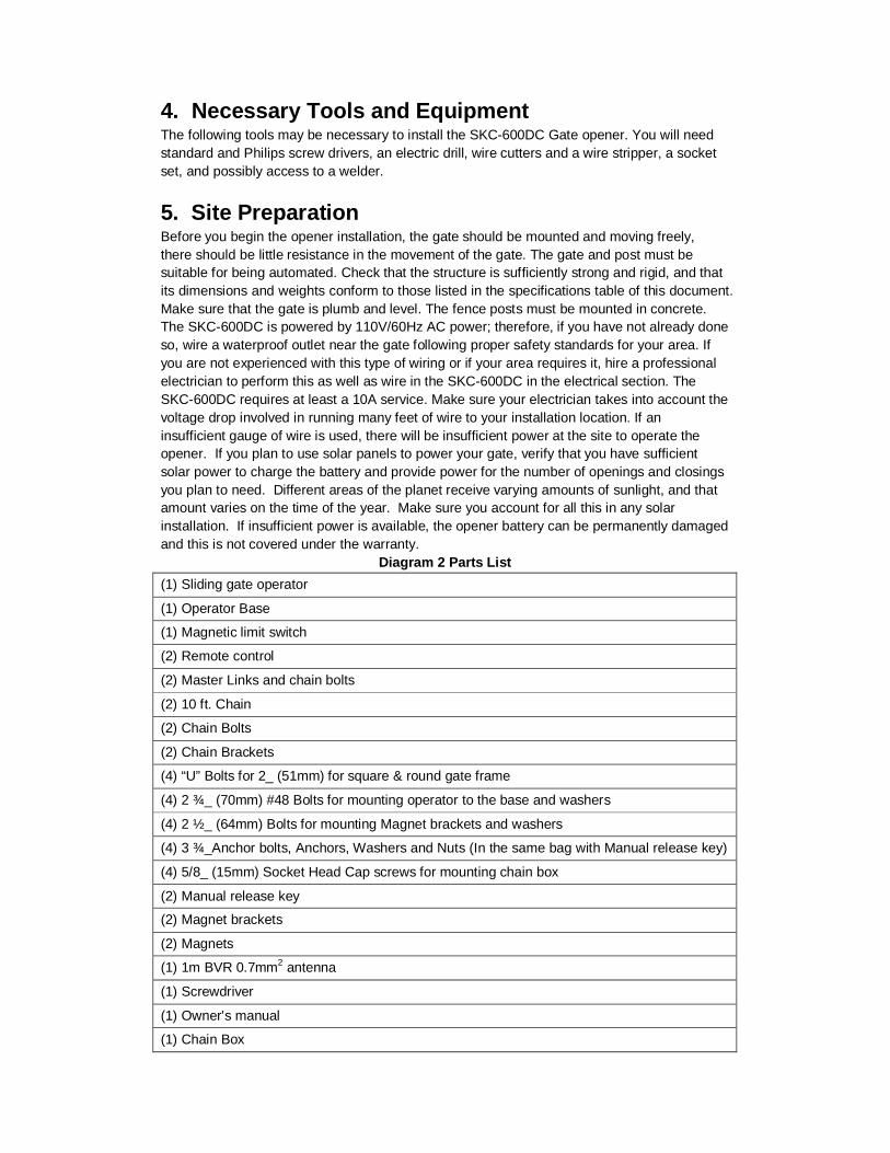
4. Necessary Tools and Equipment The following tools may be necessary to install the SKC-600DC Gate opener. You will need standard and Philips screw drivers, an electric drill, wire cutters and a wire stripper, a socket set, and possibly access to a welder.
5. Site Preparation Before you begin the opener installation, the gate should be mounted and moving freely, there should be little resistance in the movement of the gate. The gate and post must be suitable for being automated. Check that the structure is sufficiently strong and rigid, and that its dimensions and weights conform to those listed in the specifications table of this document. Make sure that the gate is plumb and level. The fence posts must be mounted in concrete. The SKC-600DC is powered by 110V/60Hz AC power; therefore, if you have not already done so, wire a waterproof outlet near the gate following proper safety standards for your area. If you are not experienced with this type of wiring or if your area requires it, hire a professional electrician to perform this as well as wire in the SKC-600DC in the electrical section. The SKC-600DC requires at least a 10A service. Make sure your electrician takes into account the voltage drop involved in running many feet of wire to your installation location. If an insufficient gauge of wire is used, there will be insufficient power at the site to operate the opener. If you plan to use solar panels to power your gate, verify that you have sufficient solar power to charge the battery and provide power for the number of openings and closings you plan to need. Different areas of the planet receive varying amounts of sunlight, and that amount varies on the time of the year. Make sure you account for all this in any solar installation. If insufficient power is available, the opener battery can be permanently damaged and this is not covered under the warranty.
Diagram 2 Parts List (1) Sliding gate operator
(1) Operator Base
(1) Magnetic limit switch
(2) Remote control
(2) Master Links and chain bolts
(2) 10 ft. Chain
(2) Chain Bolts
(2) Chain Brackets
(4) “U” Bolts for 2_ (51mm) for square & round gate frame
(4) 2 ¾_ (70mm) #48 Bolts for mounting operator to the base and washers
(4) 2 ½_ (64mm) Bolts for mounting Magnet brackets and washers
(4) 3 ¾_Anchor bolts, Anchors, Washers and Nuts (In the same bag with Manual release key)
(4) 5/8_ (15mm) Socket Head Cap screws for mounting chain box
(2) Manual release key
(2) Magnet brackets
(2) Magnets
(1) 1m BVR 0.7mm2 antenna
(1) Screwdriver
(1) Owner’s manual
(1) Chain Box
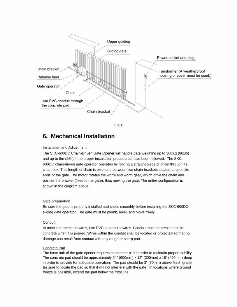
Fig.1
6. Mechanical Installation Installation and Adjustment The SKC-600DC Chain-Driven Gate Opener will handle gate weighing up to 300Kg (661lb) and up to 8m (26ft) if the proper installation procedures have been followed. The SKC-600DC chain-driven gate operator operates by forcing a straight piece of chain through its chain box. This length of chain is extended between two chain brackets located at opposite ends of the gate. The motor rotates the worm and worm gear, which drive the chain and pushes the bracket (fixed to the gate), thus moving the gate. The entire configuration is shown in the diagram above. Gate preparation Be sure the gate is properly installed and slides smoothly before installing the SKC-600DC sliding gate operator. The gate must be plumb, level, and move freely. Conduit In order to protect the wires, use PVC conduit for wires. Conduit must be preset into the concrete when it is poured. Wires within the conduit shall be located or protected so that no damage can result from contact with any rough or sharp part. Concrete Pad The base unit of the gate opener requires a concrete pad in order to maintain proper stability. The concrete pad should be approximately 24” (600mm) x 12” (300mm) x 18” (460mm) deep in order to provide for adequate operation. The pad should be 3” (70mm) above finish grade. Be sure to locate the pad so that it will not interfere with the gate. In locations where ground freeze is possible, extend the pad below the frost line.
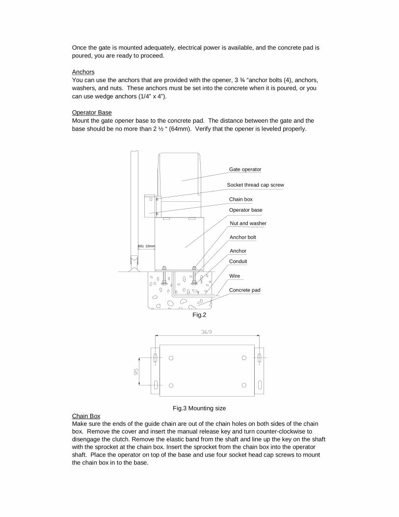
Once the gate is mounted adequately, electrical power is available, and the concrete pad is poured, you are ready to proceed. Anchors You can use the anchors that are provided with the opener, 3 ¾ “anchor bolts (4), anchors, washers, and nuts. These anchors must be set into the concrete when it is poured, or you can use wedge anchors (1/4” x 4”). Operator Base Mount the gate opener base to the concrete pad. The distance between the gate and the base should be no more than 2 ½ “ (64mm). Verify that the opener is leveled properly.
Nut and washer
Anchor
Gate operator
Wire
Operator base
Anchor bolt
Conduit
Chain box
Concrete pad
Socket thread cap screw
60± 10mm
Fig.2
Fig.3 Mounting size
Chain Box Make sure the ends of the guide chain are out of the chain holes on both sides of the chain box. Remove the cover and insert the manual release key and turn counter-clockwise to disengage the clutch. Remove the elastic band from the shaft and line up the key on the shaft with the sprocket at the chain box. Insert the sprocket from the chain box into the operator shaft. Place the operator on top of the base and use four socket head cap screws to mount the chain box in to the base.
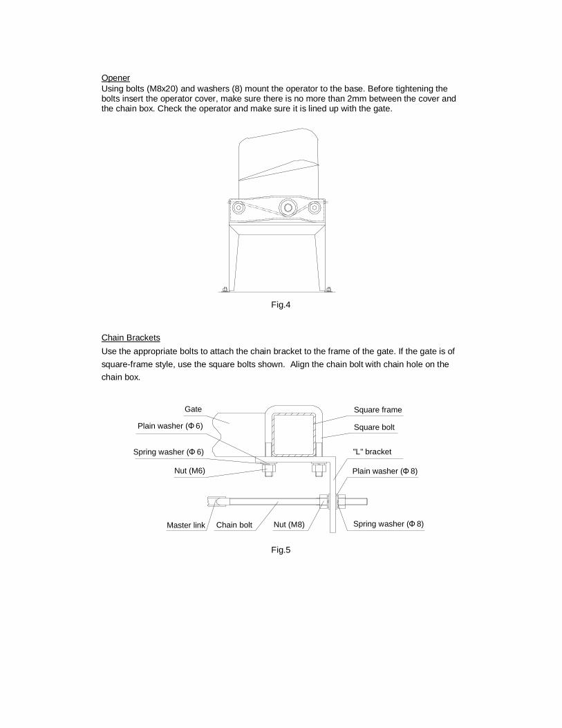
Opener Using bolts (M8x20) and washers (8) mount the operator to the base. Before tightening the bolts insert the operator cover, make sure there is no more than 2mm between the cover and the chain box. Check the operator and make sure it is lined up with the gate.
Fig.4
Chain Brackets Use the appropriate bolts to attach the chain bracket to the frame of the gate. If the gate is of square-frame style, use the square bolts shown. Align the chain bolt with chain hole on the chain box.
Spring washer (Φ 8)
Plain washer (Φ 8)
"L" bracket
Square bolt
Nut (M8)Chain bolt Master link
Nut (M6)
Spring washer (Φ 6)
Plain washer (Φ 6)
Gate Square frame
Fig.5
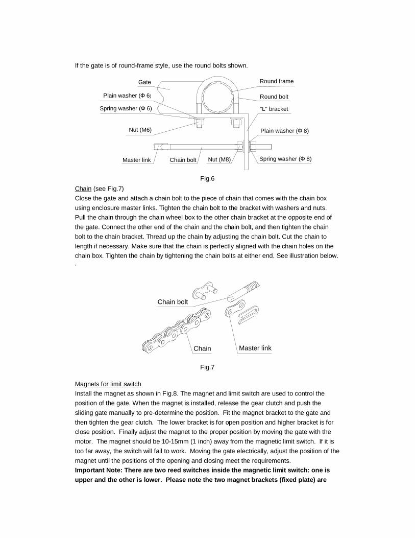
If the gate is of round-frame style, use the round bolts shown.
Round bolt
"L" bracket
Plain washer (Ф 8)
Spring washer (Ф 8)Nut (M8)Chain bolt Master link
Nut (M6)
Spring washer (Ф 6)
Plain washer (Ф 6)
Gate Round frame
Fig.6
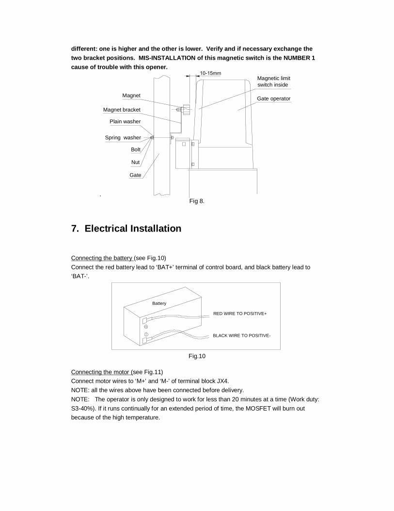
Chain (see Fig.7) Close the gate and attach a chain bolt to the piece of chain that comes with the chain box using enclosure master links. Tighten the chain bolt to the bracket with washers and nuts. Pull the chain through the chain wheel box to the other chain bracket at the opposite end of the gate. Connect the other end of the chain and the chain bolt, and then tighten the chain bolt to the chain bracket. Thread up the chain by adjusting the chain bolt. Cut the chain to length if necessary. Make sure that the chain is perfectly aligned with the chain holes on the chain box. Tighten the chain by tightening the chain bolts at either end. See illustration below. .
Master link
Chain bolt
Chain
Fig.7
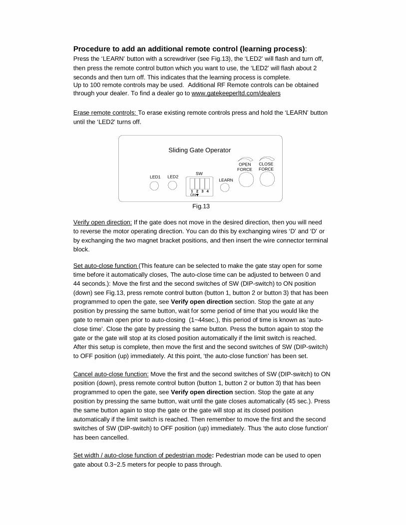
Magnets for limit switch Install the magnet as shown in Fig.8. The magnet and limit switch are used to control the position of the gate. When the magnet is installed, release the gear clutch and push the sliding gate manually to pre-determine the position. Fit the magnet bracket to the gate and then tighten the gear clutch. The lower bracket is for open position and higher bracket is for close position. Finally adjust the magnet to the proper position by moving the gate with the motor. The magnet should be 10-15mm (1 inch) away from the magnetic limit switch. If it is too far away, the switch will fail to work. Moving the gate electrically, adjust the position of the magnet until the positions of the opening and closing meet the requirements. Important Note: There are two reed switches inside the magnetic limit switch: one is upper and the other is lower. Please note the two magnet brackets (fixed plate) are
different: one is higher and the other is lower. Verify and if necessary exchange the two bracket positions. MIS-INSTALLATION of this magnetic switch is the NUMBER 1 cause of trouble with this opener.
.
Gate
Nut
Bolt
Spring washer
Plain washer
Magnet bracket
Magnet Gate operator
Magnetic limit switch inside
Fig 8.
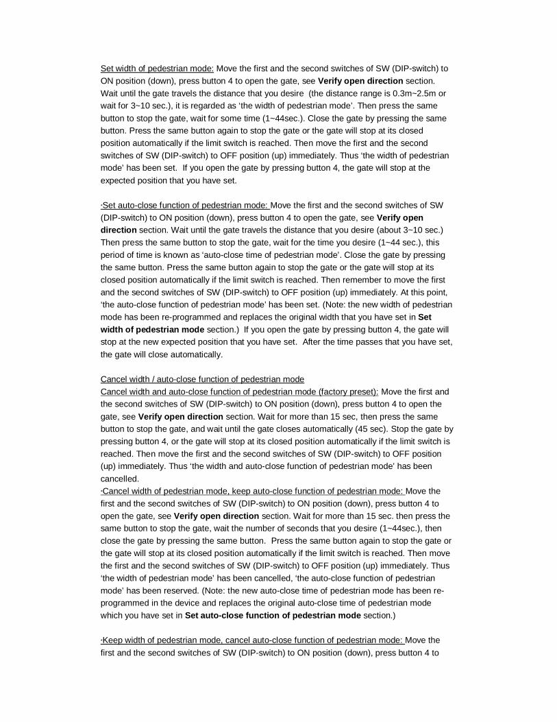
7. Electrical Installation Connecting the battery (see Fig.10) Connect the red battery lead to ‘BAT+’ terminal of control board, and black battery lead to ‘BAT-’.
Battery
BLACK WIRE TO POSITIVE-
RED WIRE TO POSITIVE+
Fig.10
Connecting the motor (see Fig.11) Connect motor wires to ‘M+’ and ‘M-’ of terminal block JX4. NOTE: all the wires above have been connected before delivery. NOTE: The operator is only designed to work for less than 20 minutes at a time (Work duty: S3-40%). If it runs continually for an extended period of time, the MOSFET will burn out because of the high temperature.

Fig 11. The control box should be equipped with a single-phase breaker (10A). Make sure that the power is OFF before making any electrical connections. Remove the cover of the control box, perform the wiring and replace the cover again. (See Fig.3 and wiring notes for control board) Wire your AC line into the AC IN terminal on JX-1. Verify that all electrical connections are waterproof by installing electrical outlets into exterior grade boxes with waterproof covers. Make sure that whenever an electrical connecter enters or exits a box it is sealed. If using solar, verify that all connections are waterproof and install solar power terminals into + and – terminals in JX-5 RF Remote Control
Button 4 Button 3
Button 1 Button 2
Fig.12
The remote control works in a single channel mode. It has four buttons. The function of button 1, button 2, and button 3 are the same. With each press of the remote control button which has been programmed, the gate will open, stop, close or stop cycle. Button 4 is available to set pedestrian mode. Note: if you cancelled the pedestrian mode, the function of button 4 is the same as the other three buttons. Warning: Notify the users that the gate is never to be operated unless it is in full view.
OPERATOR SIDE
POWER INPUT
BLACK
BROWNBLUE
BLACKRED
BLUE BLUE REDRED
BRIDGE RECTIFIER
MOSFET
TRANSFORMER
MOTOR
1413
1512
1110
98
76
54
32
1M
-M
+E
CB
-+
OPERATOR
NOT USED
NOT USEDNOT USED
NOT USED
NOT USED
NOT USED
COMMON12VDC
N/O INPUT FOR PUSH BUTTON AND KEYPAD
DC POWER INPUT
MOSFET
MOTOR
BUZZER
12VDC POSITIVE FOR PHOTOEYEN.C. PHOTOEYE INPUT
COMMON
OPEN
Procedure to add an additional remote control (learning process): Press the ‘LEARN’ button with a screwdriver (see Fig.13), the ‘LED2’ will flash and turn off, then press the remote control button which you want to use, the ‘LED2’ will flash about 2 seconds and then turn off. This indicates that the learning process is complete. Up to 100 remote controls may be used. Additional RF Remote controls can be obtained through your dealer. To find a dealer go to www.gatekeeperltd.com/dealers Erase remote controls: To erase existing remote controls press and hold the ‘LEARN’ button until the ‘LED2’ turns off.
Sliding Gate Operator
CLOSEFORCE
OPENFORCE
LEARNSW
LED2LED1
ON1 2 3 4
Fig.13
Verify open direction: If the gate does not move in the desired direction, then you will need to reverse the motor operating direction. You can do this by exchanging wires ‘D’ and ‘D’ or by exchanging the two magnet bracket positions, and then insert the wire connector terminal block.
Set auto-close function (This feature can be selected to make the gate stay open for some time before it automatically closes, The auto-close time can be adjusted to between 0 and 44 seconds.): Move the first and the second switches of SW (DIP-switch) to ON position (down) see Fig.13, press remote control button (button 1, button 2 or button 3) that has been programmed to open the gate, see Verify open direction section. Stop the gate at any position by pressing the same button, wait for some period of time that you would like the gate to remain open prior to auto-closing (1~44sec.), this period of time is known as ‘auto-close time’. Close the gate by pressing the same button. Press the button again to stop the gate or the gate will stop at its closed position automatically if the limit switch is reached. After this setup is complete, then move the first and the second switches of SW (DIP-switch) to OFF position (up) immediately. At this point, ‘the auto-close function’ has been set. Cancel auto-close function: Move the first and the second switches of SW (DIP-switch) to ON position (down), press remote control button (button 1, button 2 or button 3) that has been programmed to open the gate, see Verify open direction section. Stop the gate at any position by pressing the same button, wait until the gate closes automatically (45 sec.). Press the same button again to stop the gate or the gate will stop at its closed position automatically if the limit switch is reached. Then remember to move the first and the second switches of SW (DIP-switch) to OFF position (up) immediately. Thus ‘the auto close function’ has been cancelled. Set width / auto-close function of pedestrian mode: Pedestrian mode can be used to open gate about 0.3~2.5 meters for people to pass through.
Set width of pedestrian mode: Move the first and the second switches of SW (DIP-switch) to ON position (down), press button 4 to open the gate, see Verify open direction section. Wait until the gate travels the distance that you desire (the distance range is 0.3m~2.5m or wait for 3~10 sec.), it is regarded as ‘the width of pedestrian mode’. Then press the same button to stop the gate, wait for some time (1~44sec.). Close the gate by pressing the same button. Press the same button again to stop the gate or the gate will stop at its closed position automatically if the limit switch is reached. Then move the first and the second switches of SW (DIP-switch) to OFF position (up) immediately. Thus ‘the width of pedestrian mode’ has been set. If you open the gate by pressing button 4, the gate will stop at the expected position that you have set. ﹡Set auto-close function of pedestrian mode: Move the first and the second switches of SW (DIP-switch) to ON position (down), press button 4 to open the gate, see Verify open direction section. Wait until the gate travels the distance that you desire (about 3~10 sec.) Then press the same button to stop the gate, wait for the time you desire (1~44 sec.), this period of time is known as ‘auto-close time of pedestrian mode’. Close the gate by pressing the same button. Press the same button again to stop the gate or the gate will stop at its closed position automatically if the limit switch is reached. Then remember to move the first and the second switches of SW (DIP-switch) to OFF position (up) immediately. At this point, ‘the auto-close function of pedestrian mode’ has been set. (Note: the new width of pedestrian mode has been re-programmed and replaces the original width that you have set in Set width of pedestrian mode section.) If you open the gate by pressing button 4, the gate will stop at the new expected position that you have set. After the time passes that you have set, the gate will close automatically. Cancel width / auto-close function of pedestrian mode Cancel width and auto-close function of pedestrian mode (factory preset): Move the first and the second switches of SW (DIP-switch) to ON position (down), press button 4 to open the gate, see Verify open direction section. Wait for more than 15 sec, then press the same button to stop the gate, and wait until the gate closes automatically (45 sec). Stop the gate by pressing button 4, or the gate will stop at its closed position automatically if the limit switch is reached. Then move the first and the second switches of SW (DIP-switch) to OFF position (up) immediately. Thus ‘the width and auto-close function of pedestrian mode’ has been cancelled. ﹡Cancel width of pedestrian mode, keep auto-close function of pedestrian mode: Move the first and the second switches of SW (DIP-switch) to ON position (down), press button 4 to open the gate, see Verify open direction section. Wait for more than 15 sec. then press the same button to stop the gate, wait the number of seconds that you desire (1~44sec.), then close the gate by pressing the same button. Press the same button again to stop the gate or the gate will stop at its closed position automatically if the limit switch is reached. Then move the first and the second switches of SW (DIP-switch) to OFF position (up) immediately. Thus ‘the width of pedestrian mode’ has been cancelled, ‘the auto-close function of pedestrian mode’ has been reserved. (Note: the new auto-close time of pedestrian mode has been re-programmed in the device and replaces the original auto-close time of pedestrian mode which you have set in Set auto-close function of pedestrian mode section.) ﹡Keep width of pedestrian mode, cancel auto-close function of pedestrian mode: Move the first and the second switches of SW (DIP-switch) to ON position (down), press button 4 to
open the gate, see Verify open direction section. Wait until the gate travels the distance that you desire (the distance range is 0.3m~2.5m or wait for 3~10 sec.). Then press the same button to stop the gate, wait until the gate close automatically (45 sec.). Stop the gate by pressing the same button or the gate will stop at its closed position automatically if the limit switch is reached. Then move the first and the second switches of SW (DIP-switch) to OFF position (up) immediately. Thus ‘the width of pedestrian mode’ has been reserved, ‘the auto-close function of pedestrian mode’ has been cancelled. (Note: the new width of pedestrian mode has been re-programmed in the device and replaced the original width.) If you open the gate with button 4, the gate will stop at the expected position that you have set, but the gate will not close automatically. External Interfaces
Keypad/ Button Switch The SKC-600DC is equipped with an interface for an external switch or keypad. The interface type is a NO (Normally Open) momentary switch to ground. To activate the opener, the keypad or other device must short the ‘0’ and ‘DI’ terminal momentarily on Box JX2. This type of switch is very common. To install the device, attach one lead of your keypad to the ‘DI’ terminal and the other to the ‘0’ terminal. The keypad will function in single channel mode just like the RF remote. If the gate is closed, then activating the keypad will open the gate. If the gate is open, then activating the keypad will close the gate. If the gate is moving, then activating the keypad will stop the gate. If your keypad requires DC power, then you can use the 12 or 5 terminals and the ‘0’ terminal for ground as required by your device. See diagram 3. Consult your device manufacturer’s documentation for details. The keypad device can be obtained through your dealer. To find a dealer, go to www.gatekeeperltd.com/dealers
Loop detector A magnetic loop detector detects vehicles that are within proximity to the gate. A magnetic loop detector can be used to open the gate when a car pulls up either from the inside or the outside depending on which side of the gate you install it. A magnetic loop is usually buried under the ground, and the wires run to the gate opener control board. Magnetic loops usually require DC power, using the + and – DC terminals. They provide a normally open momentary switch interface to the control board and its ground or common interface. Wire the magnetic loop’s DC + wire to the 12 terminal on block JX3, wire the power common or ground to COM. Wire the magnetic loop’s normally open trigger wire to terminal BI and the normally open ground or common to COM both on block JX3. The terminal BI is a “free open” terminal. This means that it will only open the gate, if the gate is already opening, it will have no effect, if the gate is closing, it will override and open the gate, but triggering the terminal BI will never close the gate. Consult your device manufacturer’s documentation for details. See Figure 4 for a diagram of external interface connections. The Loop Detector device can be obtained through your dealer. To find a dealer, go to www.gatekeeperltd.com/dealers Safe guard (Infrared device or Photocell) It is recommended that the installer purchase and install infrared photocells for additional safety. Photocells work by inhibiting the movement of the gate if the beam is broken. Infrared safety devices may be required by law in some areas. If the infrared beam is broken during closing, the gates will reverse and open immediately. During opening, the beeper will ring. Infrared photocells come in active and passive varieties. Active photocells require power on both sides of the driveway, whereas passive photocells employ a reflector plate so that power is only required on one side of the driveway. Most photocells will provide DC power input wires + and -, and 2 normally closed switch wires. To install the photocell, attach the DC
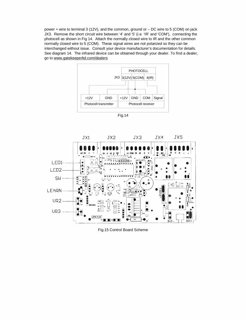
power + wire to terminal 3 (12V), and the common, ground or – DC wire to 5 (COM) on jack JX3. Remove the short circuit wire between ‘4’ and ‘5’ (i.e. ‘IR’ and ‘COM’), connecting the photocell as shown in Fig 14. Attach the normally closed wire to IR and the other common normally closed wire to 5 (COM). These signal wires are not polarized so they can be interchanged without issue. Consult your device manufacturer’s documentation for details. See diagram 14. The infrared device can be obtained through your dealer. To find a dealer, go to www.gatekeeperltd.com/dealers
Signal
Photocell receiver
+12V GNDGND+12V
Photocell transmitter
4(IR)3(12V)JX3
COM
PHOTOCELL
5(COM)
Fig.14
Fig.15 Control Board Scheme
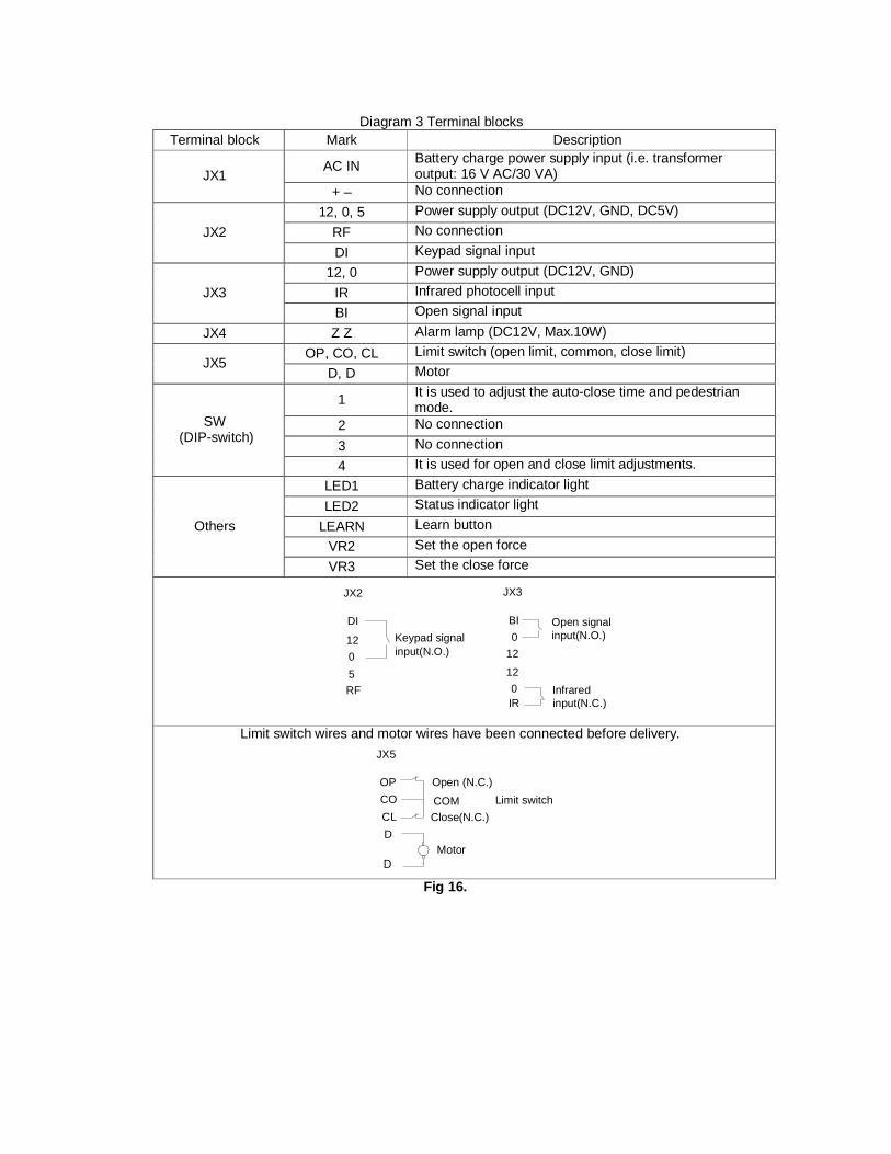
Diagram 3 Terminal blocks
Terminal block Mark Description
AC IN Battery charge power supply input (i.e. transformer output: 16 V AC/30 VA) JX1
+ – No connection 12, 0, 5 Power supply output (DC12V, GND, DC5V)
RF No connection JX2 DI Keypad signal input
12, 0 Power supply output (DC12V, GND) IR Infrared photocell input JX3 BI Open signal input
JX4 Z Z Alarm lamp (DC12V, Max.10W) OP, CO, CL Limit switch (open limit, common, close limit)
JX5 D, D Motor
1 It is used to adjust the auto-close time and pedestrian mode.
2 No connection 3 No connection
SW (DIP-switch)
4 It is used for open and close limit adjustments. LED1 Battery charge indicator light LED2 Status indicator light
LEARN Learn button VR2 Set the open force
Others
VR3 Set the close force
Infrared input(N.C.)
Open signal input(N.O.)Keypad signal
input(N.O.)
IR0
12
120BI
JX3JX2
RF5012
DI
Limit switch wires and motor wires have been connected before delivery.
JX5
OPCOCLD
D
Open (N.C.)
COMClose(N.C.)
Limit switch
Motor
Fig 16.
8. Operation
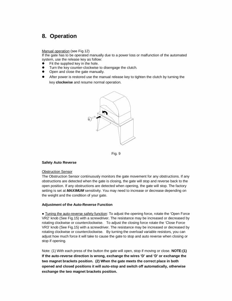
Manual operation (see Fig.12) If the gate has to be operated manually due to a power loss or malfunction of the automated system, use the release key as follow: Fit the supplied key in the hole. Turn the key counter-clockwise to disengage the clutch. Open and close the gate manually. After power is restored use the manual release key to tighten the clutch by turning the
key clockwise and resume normal operation.
Fig. 9
Safety Auto Reverse Obstruction Sensor The Obstruction Sensor continuously monitors the gate movement for any obstructions. If any obstructions are detected when the gate is closing, the gate will stop and reverse back to the open position. If any obstructions are detected when opening, the gate will stop. The factory setting is set at MAXIMUM sensitivity. You may need to increase or decrease depending on the weight and the condition of your gate. Adjustment of the Auto-Reverse Function ● Tuning the auto-reverse safety function: To adjust the opening force, rotate the ‘Open Force VR2’ knob (See Fig.15) with a screwdriver. The resistance may be increased or decreased by rotating clockwise or counterclockwise. To adjust the closing force rotate the ‘Close Force VR3’ knob (See Fig.15) with a screwdriver. The resistance may be increased or decreased by rotating clockwise or counterclockwise. By turning the overload variable resistors, you can adjust how much force it will take to cause the gate to stop and auto reverse when closing or stop if opening. Note: (1) With each press of the button the gate will open, stop if moving or close. NOTE:(1) If the auto-reverse direction is wrong, exchange the wires ‘D’ and ‘D’ or exchange the two magnet brackets position. (2) When the gate meets the correct place in both opened and closed positions it will auto-stop and switch off automatically, otherwise exchange the two magnet brackets position.
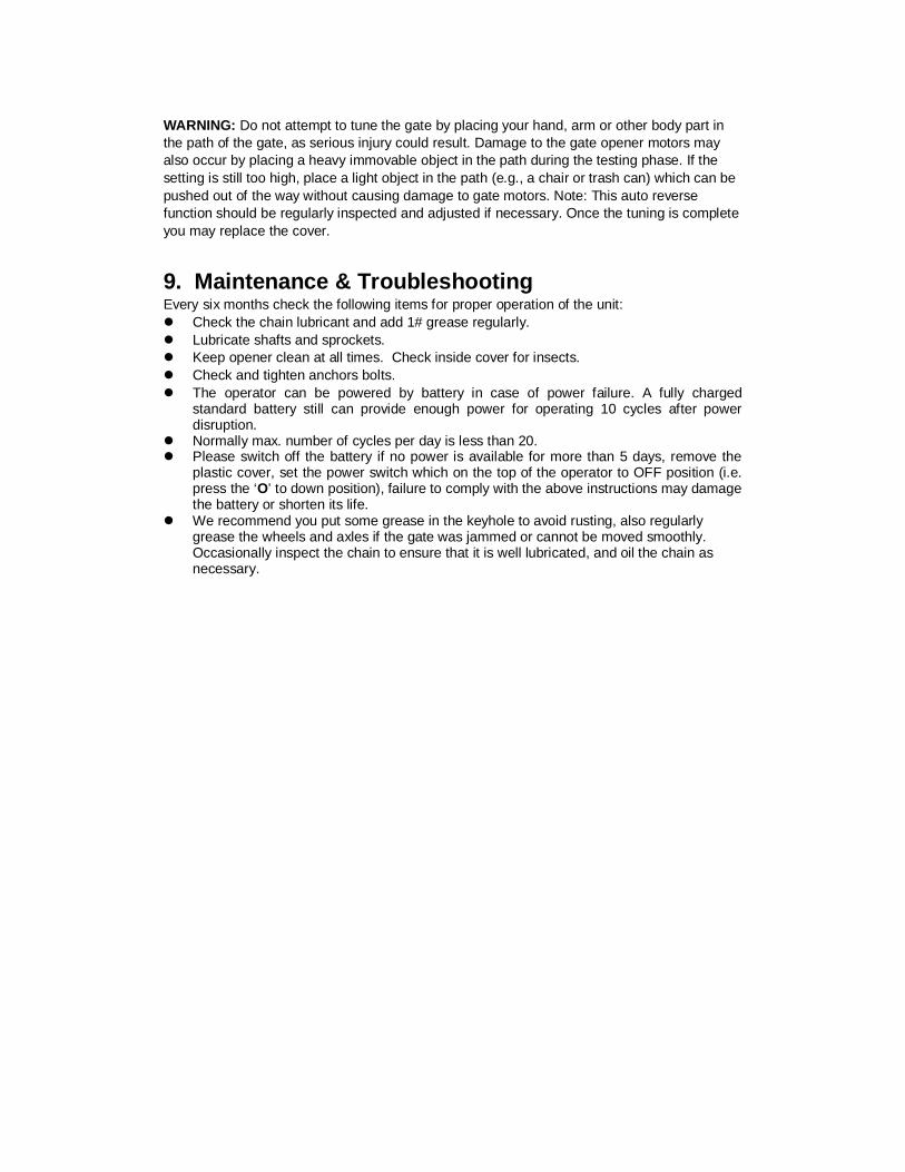
WARNING: Do not attempt to tune the gate by placing your hand, arm or other body part in the path of the gate, as serious injury could result. Damage to the gate opener motors may also occur by placing a heavy immovable object in the path during the testing phase. If the setting is still too high, place a light object in the path (e.g., a chair or trash can) which can be pushed out of the way without causing damage to gate motors. Note: This auto reverse function should be regularly inspected and adjusted if necessary. Once the tuning is complete you may replace the cover.
9. Maintenance & Troubleshooting Every six months check the following items for proper operation of the unit: Check the chain lubricant and add 1# grease regularly. Lubricate shafts and sprockets. Keep opener clean at all times. Check inside cover for insects. Check and tighten anchors bolts. The operator can be powered by battery in case of power failure. A fully charged
standard battery still can provide enough power for operating 10 cycles after power disruption.
Normally max. number of cycles per day is less than 20. Please switch off the battery if no power is available for more than 5 days, remove the
plastic cover, set the power switch which on the top of the operator to OFF position (i.e. press the ‘O’ to down position), failure to comply with the above instructions may damage the battery or shorten its life.
We recommend you put some grease in the keyhole to avoid rusting, also regularly grease the wheels and axles if the gate was jammed or cannot be moved smoothly. Occasionally inspect the chain to ensure that it is well lubricated, and oil the chain as necessary.
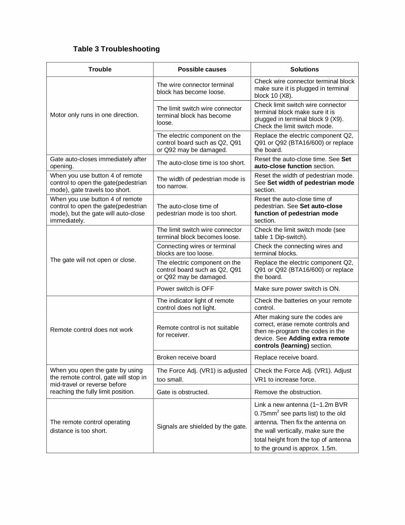
Table 3 Troubleshooting
Trouble Possible causes Solutions
The wire connector terminal block has become loose.
Check wire connector terminal block make sure it is plugged in terminal block 10 (X8).
The limit switch wire connector terminal block has become loose.
Check limit switch wire connector terminal block make sure it is plugged in terminal block 9 (X9). Check the limit switch mode.
Motor only runs in one direction.
The electric component on the control board such as Q2, Q91 or Q92 may be damaged.
Replace the electric component Q2, Q91 or Q92 (BTA16/600) or replace the board.
Gate auto-closes immediately after opening. The auto-close time is too short. Reset the auto-close time. See Set
auto-close function section. When you use button 4 of remote control to open the gate(pedestrian mode), gate travels too short.
The width of pedestrian mode is too narrow.
Reset the width of pedestrian mode. See Set width of pedestrian mode section.
When you use button 4 of remote control to open the gate(pedestrian mode), but the gate will auto-close immediately.
The auto-close time of pedestrian mode is too short.
Reset the auto-close time of pedestrian. See Set auto-close function of pedestrian mode section.
The limit switch wire connector terminal block becomes loose.
Check the limit switch mode (see table 1 Dip-switch).
Connecting wires or terminal blocks are too loose.
Check the connecting wires and terminal blocks.
The electric component on the control board such as Q2, Q91 or Q92 may be damaged.
Replace the electric component Q2, Q91 or Q92 (BTA16/600) or replace the board.
The gate will not open or close.
Power switch is OFF Make sure power switch is ON.
The indicator light of remote control does not light.
Check the batteries on your remote control.
Remote control is not suitable for receiver.
After making sure the codes are correct, erase remote controls and then re-program the codes in the device. See Adding extra remote controls (learning) section.
Remote control does not work
Broken receive board Replace receive board.
The Force Adj. (VR1) is adjusted too small.
Check the Force Adj. (VR1). Adjust VR1 to increase force.
When you open the gate by using the remote control, gate will stop in mid-travel or reverse before reaching the fully limit position. Gate is obstructed. Remove the obstruction.
The remote control operating distance is too short.
Signals are shielded by the gate.
Link a new antenna (1~1.2m BVR 0.75mm2 see parts list) to the old antenna. Then fix the antenna on the wall vertically, make sure the total height from the top of antenna to the ground is approx. 1.5m.
10. Warranty Gatekeeper Ltd. Limited Warranty
Gatekeeper Ltd. Warrants the SKC-600DC Sliding Gate Opener to be free of defects in
materials and workmanship for a period of 1 year from the date of purchase subject to certain
limitations.
This warranty shall not apply in the following circumstances, misuse, vandalism, accident,
neglect, unauthorized repair or modification, acts of God (lightning, flood, insect damage etc.),
power surge, corrosive environments, incorrect installation or application, damage to
mechanism due to wrong type of gate, incorrect weight, gate not operating freely or not on
level ground etc.
The warranty set forth here shall be entirely exclusive and no other warranty, either written or
verbal is expressed or implied, Gatekeeper Ltd and it’s dealers or distributors specifically
disclaims any and all implied warranties of merchantability or fitness for a particular purpose.
It is the purchaser’s sole and exclusive responsibility to determine whether or not the
equipment will be suitable for a particular purpose. In no event shall Gatekeeper Ltd and it’s
dealers or distributors be held liable for direct, indirect, incidental, special, or consequential
damages or loss of profits whether based on contract, tort, or any other legal theory during
the course of the warranty or at any time thereafter. The installer, purchaser and /or end-user
do agree to assume all responsibility for all liability in use of this product, releasing
Gatekeeper Ltd and it’s dealers or distributors of all liability.
For service under this warranty, please contact your dealer. All parts, accessories, service
and support for Gatekeeper products is supplied through our network of dealers. Dealer
information can be obtained at www.gatekeeperltd.com/dealers

Gatekeeper Ltd. P.O.Box 752
Laceys Spring, AL 35754 [email protected]
For updated versions of the manual see: http://www.gatekeeperltd.com
For Additional Remotes, Infrared Photo Cells or
Parts please contact your dealer. To locate a dealer, please visit us at:
www.gatekeeperltd.com/dealers