Installer instructions · Domestic sliding gate ... especially children are clear of the gate and...
30
UMPETHA 082009/072010.014 1 Domestic sliding gate operator by ET SYSTEMS. Installer instructions
Transcript of Installer instructions · Domestic sliding gate ... especially children are clear of the gate and...

UMPETHA 082009/072010.014
1
Domestic sliding gate operator by ET SYSTEMS.
Installer instructions

UMPETHA 082009/072010.014
2
Table of contents
Page Category
Introduction
3 Safety obligations and general warnings
4 Identification of components
5 Technical specifications
6 Before installing preparation
7 Cable requirements
Hardware installation
8
9 Installing the baseplate and positioning motor
10 Inserting or remov ing battery and mounting of motor to baseplate
11 Installing the rack
13 Installing the limit actuator
14 Control card wiring layout
Motor control programming
15 Run time set-up
16 Auto-close time programming
17 Pedestrian opening and pedestrian auto-close time programming
18 Changing the crawl distance
19 Changing the switch type input for the beams
20 Adjusting the safety sensing lev el
Receiver programming
21 Master erase
22 Registering a transmitter using the receiv er pins
23 Registering a transmitter using the master remote transmitter
Operating mode selection
24 Standard mode
24 Simple auto-close mode
24 Complex auto-close/Condominium mode
25 P.I.R.A.C. mode
Additional features
26 Holiday lock-out
26 Beam Alarm Output (B.A.O)
27 Auto-close ov erride/party mode
27 Pedestrian operation
27 Courtesy light functionality
Trouble shooting
28 Buzzer indication trouble shooting guide
28 Status LED indication guide
29 Warranty
Accessing manual override and remov ing cov er

UMPETHA 082009/072010.014
3
WARNING TO THE INSTALLER. GENERAL SAFETY OBLIGATIONS.
Caution! It is important for personal safety to follow all the instructions carefully. Incorrect installation or misuse may cause serious
personal harm.
Keep the instructions in a safe place for future reference.
This product was designed and manufactured strictly for the use indicated in this documentation. Any other use not expressly
indicated in this documentation, may damage the product and/or be a source of danger.
We accept no responsibility due to improper use of this product.
Care must be taken not to install this product in an unsafe environment. I.e. near inflammable gases and or fumes.
We will not accept responsibility if the principles of good workmanship are disregarded by the installer. The construction of the
gate must be sound and automatable. It is the responsibility of the installer to ensure that all mountings to the gate are sufficient to
withstand the necessary forces in cases of overload.
Before carrying out any work on the product, ensure that the electrical supply is switched off.
It is highly recommended that a set of safety infra-red beams be used in conjunction with this product.
We accept no responsibility regarding safety and correct operation of the automation if other manufacturer’s equipment is added
to this product.
Do not make any modifications or alterations to this product.
It is the responsibility of the installer/ service provider to completely instruct and demonstrate the proper use of this product,
especially the emergency override, to the end user. It is also the responsibility of the installer/ service provider to issue all end user
documentation, which accompanies this product, to the end user.
Ensure that other persons, especially children are clear of the gate and opener before and during operation.
Keep remote transmitters away from children to prevent accidental activation of the system.
The end user should refrain from attempting to make any repairs or adjustments to the system and should contact professional
qualified assistance timorously.
Anything other than expressly provided for in these instructions is not permitted.
The electrical supply to this product must comply with the local electrical code of practice and any electrical work must be carried
out by a qualified electrician.
Over and above the recommendation to use safety infra-red beams with this product it is mandatory to ensure a set has been
installed and is in proper working condition when using the automatic closing feature.

UMPETHA 082009/072010.014
4
1. Plug in terminal connectors 13. Motor mounting slot
2. Control card 14. Manual override cam sensor magnet
3. Control card holder 15. Gearbox housing
4. Battery 16. Manual override cam reed switch sensor
5. Antenna 17. DC to DC switch-mode 12V Aux supply module
(300mA peak)
6. 220Vac 500mA fast blow fuse for primary supply* 18. Serial number
7. 220Vac 15A fixed terminal connections* 19. 24Vdc Fixed magnet motor
8. Inline unidirectional battery plug (polarized) 20. Revolution counter magnet
9. Cable entry point 21. Closed limit reed switch sensor
10. Manual override lock with protection flap 22. Base plate
11. Manual override cam 23. Pinion gear
12. Base plate 24. Pinion gear protection flange
*For built in transformer model.
UMPETHA 082009/072010.014
5
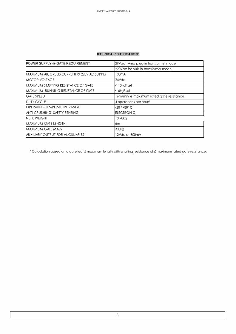
TECHNICAL SPECIFICATIONS
* Calculation based on a gate leaf ≤ maximum length with a rolling resistance of ≤ maximum rated gate resistance.
POWER SUPPLY @ GATE REQUIREMENT 29Vac 1Amp plug-in transformer model
220Vac for built in transformer model
MAXIMUM ABSORBED CURRENT @ 220V AC SUPPLY 100mA
MOTOR VOLTAGE 24Vdc
MAXIMUM STARTING RESISTANCE OF GATE < 10kgF set
MAXIMUM RUNNING RESISTANCE OF GATE < 6kgF set
GATE SPEED 16m/min @ maximum rated gate resistance
DUTY CYCLE 4 operations per hour*
OPERATING TEMPERATURE RANGE
ANTI-CRUSHING SAFETY SENSING ELECTRONIC
NETT. WEIGHT 10.70kg
MAXIMUM GATE LENGTH 6m
MAXIMUM GATE MASS 300kg
AUXILIARY OUTPUT FOR ANCILLIARIES 12Vdc at 300mA
-10 / +50° C
UMPETHA 082009/072010.014
6
BEFORE ATTEMPTING TO INSTALL A SLIDE GATE OPERATOR, PLEASE BE CERTAIN YOU HAVE READ AND
UNDERSTOOD THE FOLLOWING TO ENSURE CONTINUED SATISFACTORY SAFE SERVICE FROM THIS PRODUCT:
The following are points to note before installing your new slide gate operator:
1. Gate mechanics
2. Cabling requirements
GATE MECHANICS
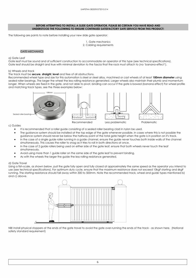
a) Gate Leaf
Gate leaf must be sound and of sufficient construction to accommodate an operator of this type (see technical specifications).
Gate leaf should be straight and true with minimal deviation to the fascia that the rack must attach to (no ‘banana-effect’).
b) Wheels and track
The track must be secure, straight, level and free of all obstructions.
Recommended wheel type and size for this automation is steel or steel alloy, machined or cast wheels of at least 100mm diameter using
sealed roller bearings. The larger the wheel the less rolling resistance generated. Larger wheels also maintain their plumb and momentum
longer. When wheels are fixed in the gate, and not able to pivot, binding can occur if the gate is bowed (banana effect) For wheel profile
and matching track types, see the three examples below:
Recommended Less problematic Problematic
c) Guides
It is recommended that a roller guide consisting of a sealed roller bearing clad in nylon be used.
The guidance system should be installed at the top edge of the gate whenever possible. In cases where this is not possible the
guidance system should never be below the halfway point of the total gate height when the gate is in position on it's track.
In the case of a single guide roller running in a guide channel, ensure the guide never touches both inside walls of the channel
simultaneously. This causes the roller to snag as it tries to roll in both directions at once.
In the case of 2 guide rollers being used on either side of the gate leaf, ensure that both wheels never touch the leaf
simultaneously.
Avoid using more than 1 guide roller on the same side of the gate leaf to prevent binding.
As with the wheels the larger the guide the less rolling resistance generated.
d) Gate Travel
Using a fish-scale, as shown below, pull the gate fully open and fully closed at approximately the same speed as the operator you intend to
use (see technical specifications). For optimum duty cycle, ensure that the maximum resistance does not exceed 10kgF starting and 6kgF
running. The starting resistance should fall away within 300 to 500mm. Note the recommended track, wheel and guide types mentioned b)
and c) above.
NB! Install physical stoppers at the ends of the gate travel to avoid the gate over-running the ends of the track - as shown here. (National
safety standard requirement)

UMPETHA 082009/072010.014
7
CABLING REQUIREMENTS
Before mounting the operator ensure your cabling and conduiting are in place to prevent any inconvenience at a later stage. Allow for
spare cabling in case of faulty cable & breakages (especially important when using low specification cable). If installing an intercom,
remember to allow for sufficient cable cores for all the uses on the system as per manufacturers cabling requirements.
1
7
6
8
4
1
2
4
5
3
2. Safety infra-red beam power (2-core)
3. Safety infra-red beam power & switch (4-core)
4. Courtesy lights (twin + earth 1.0mm)
1. Intercom gate station (check with intercom
supplier specifications)
5. Free exit loop (1.5mm silicone insulated single
core flexible stranded)
6. Primary power: Plug in transformer model - twin:
min 0,5mm Internal in-line transformer model
(220Vac) - twin + earth: 1,0mm
7. From intercom internal equipment (check with
intercom supplier specifications)
8. Optional earth-rod for high lightning strike areas
(preferably use household earth leakage)

UMPETHA 082009/072010.014
8
Manually overriding the gearbox and removing the cover
Locked and engaged Unlocked and engaged
Insert key and turn
clockwise.
Unlocked and
disengaged
Cover housing screw
beneath manual
override cam
Second cover screw
Fourth cover screw Third cover screw
Remember to pull or push the gate gently until the gears “click” re-engage, before running the motor after a manual override.
When the override cam is in the manual override position the electronic control is disabled. To operate the control card the cam
must be in the engaged position.

UMPETHA 082009/072010.014
9
Motor positioning to gate.
Hot tip: Cast the track plinth at the same time as the motor plinth
Install the base plate on the protected side of the driveway wherever possible. (opposite side of the guide post to the driveway) The base
plate must be installed 30 to 50mm away from the proudest part of the gate. The wheel bolt is the proudest part of the gate here. If in doubt
rather install the base plate further away and use spacers between the gate fascia and the rack when installing the rack.
30 to 50mm between the proudest part of the
gate and the edge of the base plate
Guide post
Driv
ew
ay
300mm
200
mm
300
mm
3
00
mm
Base plate
Conduiting
Pre-cast concrete
plinth
Coach screws through
angle mounting tabs
10mm masonry drill bit.
Freshly cast concrete
plinth
Conduiting
Roofing bolts pre-
assembled onto base
plate
Base plate
Fold out tabs
Top view
Sectional side view of a baseplate set in a freshly cast plinth
Sectional side view of a baseplate mounted on a previously cast plinth

UMPETHA 082009/072010.014
10
Inserting and removing the battery
Fastening the operator to the base plate
Fasten motor to the base plate using the bolts and plates from the top as
shown here
Be careful that the cables are
not trapped and damaged
when fastening or adjusting the
motor on the base plate
Please note! In the cases where something like
the gate guide post or a wall is obstructing the
battery from being angled to one side, making
it impossible to insert or remove the battery
then carefully remove the control card and
control card holder before removing the
battery.
Remember to ensure the control card and
holder are both secured in place correctly
when finished.
UMPETHA 082009/072010.014
11
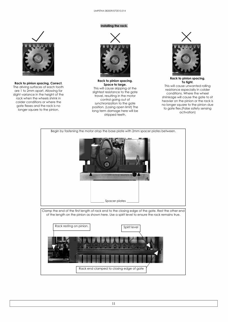
Installing the rack.
Rack to pinion spacing. Correct.
The driving surfaces of each tooth
are 1 to 2mm apart. Allowing for
slight variance in the height of the
rack when the wheels shrink in
colder conditions or where the
gate flexes and the rack is no
longer square to the pinion.
Rack to pinion spacing.
Space to large.
This will cause skipping at the
slightest resistance to the gate
travel, resulting in the motor
control going out of
synchronization to the gate
position. (Losing open limit) The
long term damage here will be
stripped teeth.
Rack to pinion spacing.
To tight.
This will cause unwanted rolling
resistance especially in colder
conditions. Where the wheel
shrinkage will cause the gate to sit
heavier on the pinion or the rack is
no longer square to the pinion due
to gate flex.(False safety sensing
activation)
Begin by fastening the motor atop the base plate with 2mm spacer plates between.
Spacer plates
Clamp the end of the first length of rack end to the closing edge of the gate. Rest the other end
of the length on the pinion as shown here. Use a spirit level to ensure the rack remains true.
Rack resting on pinion. Spirit level
Rack end clamped to closing edge of gate

UMPETHA 082009/072010.014
12
If satisfied with the rack level fasten the first “TEK” screw (supplied) in the middle of the slot
nearest the closing edge of the gate.
Move the gate towards the open position. Far enough that you can access the last mounting slot
at the opposite end of the length of rack to the end already fastened. Fasten the next “TEK”
screw here while the rack still rests atop the pinion.
To install additional lengths of rack, move gate closed until the next length of rack meets the first
length and the opposite end once again rests on the pinion. To ensure the 2 lengths of rack
marry correctly use an off cut of rack clamped upside down across the join of the 2 lengths.
Continue to fasten the “TEK” screws as before.
When finished installing sufficient rack to allow for the full travel of the gate plus enough to allow
for the limit actuator (as shown in the next section) remove the spacer plates and test the
meshing of the rack and pinion. (See above pictures of rack spacing). If satisfied fasten a “TEK”
screw directly through both the rack angle and the gate so that you have 5 “TEK” screws per
length of rack evenly spaced.

UMPETHA 082009/072010.014
13
Installing the limit actuator
(Mandatory before programming)
1. Push the gate up against the closed stopper/keep.
2. Place magnetic actuator on top of the rack where it is half way across the reed switch. See below
3. Remove the rack screw (Holding the nylon teeth to the steel angle) closest to the middle of the slot in the actuator.
4. Replace this screw with the longer screw provided with the actuator.
5. Adjust the stopping position by sliding the actuator sideways. Check the closed limit LED while doing this.
After programming the run-time (page 15) the gate should stop a minimum of 10-20mm from the mechanical end stop. Adjust the
actuator if necessary.
Slot insert
Limit actuator
Reed
switch
Fastening
screw
Limit LED
Top view
Default
direction See point 4
on page 15
Rack

UMPETHA 082009/072010.014
14
Control card layout and wiring.

UMPETHA 082009/072010.014
15
Runtime Setup
Action Response
Gate starts opening
Gate stops and closes
1 beep
Remove program jumper or continue to next feature
Gate stops, 1 beep
Gate will now close correctly
Gate starts opening
Gate stops and closes
Continuous beep off
The run- time routine must be completed before attempting to continue with any other routine! The closed
limit actuator must be installed correctly before starting this routine!
1. Gate midway and engaged.
2. Program jumper on
2 beeps
3. All dip-switches off.
4. Press and release Set button Gate must close. If gate opens first
press and release set button then
see A below!
5. At closed limit
6. Press and release Set button at
required full open position (± 25mm short
of physical stopper)
7. At closed position
*** Changing gate direction if it opens first above.
A) On pressing and releasing the set
button while gate was opening first
B) Dip-switch 3 on
C) Press and release Set button
D) At closed limit
E) Press and release Set button at
required full open position (± 25mm
short of physical stopper)
F) At closed position1 beep, pause, continuous
beep.
G) Dip-switch 3 off

UMPETHA 082009/072010.014
16
Auto-close time:-
(Default = 15sec.)
NB! The auto-close mode type must be selected after all programming is completed.
(See operating mode selection on page 24)
Action Response
2 beeps
Continuous beep
Continuous beep stops
To change the time again without leav ing programming, repeat from point 2.
Remov e program jumper or continue to another programming option.
NB! This does not activate the Auto-close function. For this see selecting operating modes on page 24
1. Program jumper on
2. Dip-switch 1 on
3. Press and hold Set button,
count beeps for required auto-
close time.
1 beep = 1sec.
2 beeps = 2sec.
....cont
255 beeps = 4.25 min. (Max)
4. Release Set button at
required auto-close time
5. Dip-switch 1 off

UMPETHA 082009/072010.014
17
Pedestrian opening distance and independent pedestrian auto-close time:-
(Default = ± 1m opening and 5sec. auto-close time)
Action Response
Gate midway and engaged
1. Program jumper on 2 beeps
2. Dip-switch 2 on
3. Press and release Set button Gate closes
4. At closed position Gate opens
Gate stops
Gate closes
8. At closed position Continuous beep
9. Dip-switch 2 off Continuous beep stops
To change the pedestrian parameters again without leav ing programming, repeat from point 2.
5. Press and release Set button at
required open distance
6. Press and hold Set button,
count
beeps for auto-close time.
1 beep = 1sec.
2 beeps = 2sec.
....cont
255 beeps = 4.25 min. (Max)
7. Release Set button at required
auto-close time
Remove program jumper or continue to another programming option

UMPETHA 082009/072010.014
18
Changing crawl distance:-
Default: - 350mm
Action Response
2 beeps
Continuous beep
Continuous beep off
To change again without leav ing programming, repeat from point 2.
Remov e program jumper or continue to another programming option
1. Program jumper on
2. Dip-switch 4 on
3. Press and release Set button
Beeps confirm change
1 beep = 350mm
2 beeps = 700mm
4. Dip-switch 4 off

UMPETHA 082009/072010.014
19
Changing switch type for safety beam input:-
Default:- Normally open
Action Response
2 beeps
After confirmation beeps Continuous beep
Continuous beep off
To change again without leav ing programming, repeat from point 2.
Remov e program jumper or continue to another programming option
1. Program jumper on
2. Dip-switch 1 and 2 on
3. Press and release Set button
Beeps confirm change
1 beep = N/C
2 beeps = N/O (Default)
4. Dip-switch 1 and 2 off
UMPETHA 082009/072010.014
20
Collision/obstruction/hindrance while opening. (All modes)
If a collision, obstruction or hindrance is encountered before the full open position is reached while opening, the gate will stop, back off and
wait for the next trigger input, before closing slowly. The status LED will flash rapidly once stationery after backing off of collision. Closing
trigger clears the status LED indication. For trigger responses see page mode selection on page 23.
Collision/obstruction/hindrance while closing. (All modes)
If a collision, obstruction or hindrance is encountered while closing, the gate will stop and reverse to the fully open position. The status LED
will flash rapidly once stationery after opening away from the collision. The next trigger input starts the gate closing slowly. Closing trigger
clears the status LED indication. For trigger responses see mode selection on page 24.
Multiple collision/obstruction lock-outs. (All modes)
On encountering 4 consecutive obstructions while closing the gate, the UMPETHA will not reverse back to the full open position. The response
will be a 5 sec beep tone, followed by a gentle momentary reverse away from the obstruction. The unit will now begin a mandatory 30sec
lockout whereby the only response to any trigger input will result in a tone so long as the trigger button is held. After 30sec a trigger input will
result in a repeat of the 5 sec beep and the gate opening 1 meter or to the full open position whichever is reached first. The unit will once
again lock out. This time the user must manual release the unit and test the travel by hand before attempting any further automation of the
gate.
The Status LED will flash rapidly throughout this procedure indicating a multiple obstruction lock-out has occurred.
Releasing the gearbox and re-engaging it will clear the LED status and the multiple obstruction lock-out routine.
Collision with closed stopper due to faulty or missing closed limit. (All modes)
If no limit input is made when expected (as calculated by the programmed run time) the UMPETHA will not reverse back to the open position
as it normally would when obstructed. It will however stop at the point of impact with the closed catch and emit a 5sec long beep tone. At
the next valid opening trigger the UMPETHA will re-emit the 5sec long beep tone and only open the gate by ±1 meter. This will allow for the
user to be able to enter the property and manually override the gate. The magnet actuator and limit can now be checked. If not
corrected and further attempts are made to operate the UMPETHA with a faulty closed limit condition the same routine will be repeated on
every operation.
If the user continues to attempt to operate the gate without manually releasing the gearbox while the gate is at the ±1meter position, the
result will only be a repeat of the 5sec beep tone.
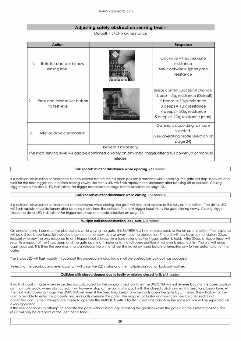
Default: - 5KgF max resistance
Action Response
Repeat if necessary.
Adjusting safety obstruction sensing level:-
1. Rotate Load pot to new
sensing level.
Clockwise = heav ier gate
resistance
Anti-clockwise = lighter gate
resistance
2. Press and release Set button
to test level
Beeps confirm successful change
1 beep = 5kg resistance (Default)
2 beeps = 10kg resistance
3 beeps = 15kg resistance
4 beeps = 20kg resistance
5 beeps = 22kg resistance (max)
3. After audible confirmation.
Gate runs according to mode
selected.
(See operating mode selection on
page 24)
The load sensing level will also be confirmed audibly on any initial trigger after a full power up or manual
release.

UMPETHA 082009/072010.014
21
Receiver programming: - Master erase;
Action Response
All power off
Power up
Power up RX (receiv er) LED on
Short both PED (pedestrian) and
BT (full opening) pins to center pin
(Use the key-ring supplied with the
transmitters to do this as shown
here)
RX (receiv er) LED flashes rapidly -
stops flashing - on continuously.
Remove all power
Remove RX (receiv er) pins short

UMPETHA 082009/072010.014
22
Learning a remote transmitter button in the receiver for BT open/close operation: -
(25 user memory)
Action Pictorial confirmation Response
Press and hold the required remote
transmitter button
RX LED flickers lightly.
Short circuit the middle RX
programming pin to the BT pin.
(Furthest from the gate)
RX LED flashes
Confirmation.
1 flash = First transmitter learnt.
2 flashes = Successful there is still
memory available.
Multiple rapid flashes = memory full.
Remove the short circuit once the
RX LED flashes confirmation.
RX LED remains lit in standby.
Release remote transmitter button
Learning a remote transmitter button in the receiver for the pedestrian operation: -
(6 user memory)
Action Pictorial confirmation Response
Press and hold the required remote
transmitter button
RX LED flickers lightly.
Short circuit the middle RX
programming pin to the PED pin.
(Closest to the gate)
RX LED flashes
Confirmation.
1 flash = First transmitter learnt.
2 flashes = Successful there is still
memory available.
Multiple rapid flashes = memory full.
Remove the short circuit once the
RX LED flashes confirmation.
RX LED remains lit in standby.
Release remote transmitter button

UMPETHA 082009/072010.014
23
Learning a TX button for BT (Full opening) operation using the RX (receiver) Master remote: -
(25 user memory)
Action Response
Continues to beep.
To continue adding remotes repeat from point 2.
The RX (receiv er) Master remote can only be learnt into memory using the RX (receiv er) pins!
The RX (receiv er) Master remote is the first remote learnt into the BT (full opening) memory and it
must be able to operate the PED(pedestrian) function of the built-in RX (receiv er) as well.
Feature not av ailable in Condo/loop mode
Feature limited to learning in BT (full opening) operation transmitters only.
1. Open gate fully using the
RX (receiv er) master remote
Gate runs to full open position and
stops
2. Press and hold RX
(receiv er) Master remote
pedestrian button.
Start of 5sec. Beep. Waiting for new
remote trigger.
3. Release RX(receiv er)
Master remote pedestrian
button
4. Press and hold required
button on new TX
(transmitter)before learn
mode timer expires and
beep stops.
Long beep changes to.....
2 beeps = Successful there is still memory
av ailable
Multiple rapid beeps = memory full
No beep = Button already in RX
(receiv er) memory or non ET Blue TX
(transmitter) used.
If no new TX (transmitter) button is pressed within 5 seconds of the continuous beep beginning,
then the RX (receiv er) will exit learn mode. All functions return to normal.

UMPETHA 082009/072010.014
24
Operating mode selection
(Program jumper off)
Dip-switch selection Mode
Dip-switch 1 ON (only) Simple Auto-close
As per Standard mode abov e howev er the following differs: -
The unit times out the pre-programmed auto-close time when stopped in any open position. Once the
auto-close time has expired it begins closing the gate.
While closing the gate any BT (full opening) or BM (beam) input will stop and rev erse the motor direction
back towards the full open position.
In any open position while auto-close is timing out a BM (beam) input will reset the auto-close timer.
Auto-close ov erride/Party mode is av ailable in this mode. (See additional features below)
Holiday lock out is av ailable in this mode. (See additional features below)
Master remote programming is av ailable in this mode. (See page 23)
Dip-switch selection Mode
All off Standard (Four step logic)
When the motor is activ ated using any BT (full opening) input the gate will open or close and can be
stopped in mid cycle using any BT (full opening) input again.
The gate can then be rev ersed by activ ating the BT (full opening) input again.
In this mode the gate will remain open where it has been stopped either by button or open limit until the BT
(full opening) input is activ ated again. (No auto close)
Party mode is av ailable in this mode. (See additional features below)
Holiday lock out is av ailable in this mode. (See additional features below)
Master remote programming is av ailable in this mode. (See page 23)

UMPETHA 082009/072010.014
25
Dip-switch selection Mode
Dip-switch 2 ON (only)Complex Auto-close/Condominium
(select when using a loop detector)
In this mode any BT (full opening) input trigger is treated as an opening trigger. On reaching the full open
position the unit times out the pre-programmed auto-close time after which it will begin closing the gate.
If the BM (beam) or BT (full opening) input is activ ated while the auto-close timer is running the time will
simply reset.
On closing any BT (full opening) input or BM (beam) input will re-open the gate to the full open position.
USE THIS MODE WHEN CONNECTING A LOOP DETECTOR.
Auto-close ov erride/Party mode is NOT av ailable in this mode. (See additional features below)
Holiday lock out is NOT av ailable in this mode. (See additional features below)
Master remote programming is NOT av ailable in this mode. (See page 23)
Dip-switch selection Mode
Auto-close ov erride/Party mode is av ailable in this mode. (See additional features below)Holiday lock out is av ailable in this mode. (See additional features below)
Master remote programming is av ailable in this mode. (See page 23)
Dip-switch 3 ON (only)P.I.R.A.C. Auto-close
(Passiv e-infra-red access control)
In this mode the unit will operate as per Simple auto-close abov e. The added feature here is quick closing
once the BM (beam) input has been activ ated and cleared.
I.e The gate is opening; a car enters the beams and passes right through. The BM (beam) input is now clear
again and the gate immediately closes.
If the gate reaches the full open position the pre-programmed auto-close timer times out after which the
gate will begin closing.
Except when used in conjunction with Complex auto-close mode.

UMPETHA 082009/072010.014
26
Beam alarm output (BAO).
Available in all modes.
The Alarm output will trigger if the BM (Beam) input is activated continuously for ≥ 20sec while the gate is in
the closed position. This output should be connected to an “ET Relay on board” which in turn can be
connected to a zone on the alarm system or simply a light that the user can easily see when approaching
the gate. In this way the user can identify if someone has tampered with the beams trying to prevent the
gate from closing again once they have entered the property.
The Beam alarm output will de-activate as soon as the interference/tamper is removed.
Additional functions
Action Response
Until 5sec beep begins.
To unlock repeat
Holiday lock-out
Av ailable in all but Complex Auto-close mode.
1. Close gate
2. Press and hold the PED (pedestrian)
button on a master remote
3. Release PED (pedestrian) button on
master remote
Beeping will continue until confirmation or
5sec expires.
4. Press and release BT (full opening)
button on the master remote before 5sec
beep stop.
1 x multiple rapid beeps will confirm
holiday lock-out is activ e.
After multiple confirmation beeps gate
will immediately start opening when
unlocked.
Holiday lock-out is av ailable only when using a master remote. (No hardwired dev ices will activ ate)
A master remote is a remote that has BT (full opening) control as well as PED (Pedestrian) opening control.
If no BT (full opening) confirmation trigger is receiv ed by the time the intermittent beeps stop (5sec.), the gate
will not change status.

UMPETHA 082009/072010.014
27
Auto-close override
Action Response
1 x long beep and gate starts closing.
Party mode
Av ailable in all but Complex Auto-close mode.
1. With the gate at any open position
2. Press and hold any TX (transmitter)
BT (full opening) button
After 5sec unit will emit Multiple rapid
beeps to confirm.
3. Release input after beepsGate will not begin closing after auto-
close time has expired.
4. To deactiv ate repeat 2 and 3
abov e
If any PED (Pedestrian) or BT (full opening) input is momentarily activ ated while the unit is in either Holiday
lock-out or Auto-close ov erride/Party mode the unit will only emit the multiple rapid beeps and not run the
gate.
Action Response
Pedestrian opening
Available in all modes.
1. Gate in closed position
2. Press and release any PED
(pedestrian) input.
A) 3 x 1sec beeps after which gate opens
to pedestrian opening position.
B) At pedestrian opening position
pedestrian auto-close timer times out.
C) 3 x 1sec beeps after which gate re-
closes.
Any further PED (pedestrian) input triggers while the gate is running are ignored except in the pedestrian
opening position, where the auto-close timer will simply reset.
Any BM (beam) input while the pedestrian routine is running will cause the gate to continue to the pedestrian
opening position or rev erse back to the pedestrian opening position. If already in the pedestrian opening
position, the auto-close timer will simply reset.
Any BT (full opening input while the pedestrian routine is running will open the gate to the full open position
and the unit will rev ert to the operating mode selection that has been setup.

UMPETHA 082009/072010.014
28
Beeps Gate status Program
Jumper Action
Response
Motor Condition Solution Table ref:
5 x Rapid
beeps Full closed Off
Momentary
BT or Ped
input
None Holiday lock-
out active Toggle off pg 26
Continuous
rapid beeps
Gate
anywhere On None None
Holiday lock-
out active Toggle off pg 26
5 x Rapid
beeps
Gate
anywhere
but closed
Off
Momentary
BT or Ped
input
None
Auto-close
override/party
mode active
Toggle off pg 27
1 x 5sec beep
(long beep)
Opens 1m
and remains
there.
Off
Momentary
BT or Ped
input
None limit failure check magnet on
gate and limit switch pg 20
2 x Rapid
beeps
Gate
anywhere Off or On
Momentary
BT or Ped
input
Attempts to run Battery flat or
faulty
Allow recharge and
check for Aux devices
overload. If problem
persists after ±8 hours
charging, replace
battery
3 x 1sec. Beeps Gate closed Off Momentary
Ped
Gate opens
partially
Pedestrian
function
activated
pg 27
2 x 2sec. Beeps Gate
stopped Off
Momentary
BT Gate runs
Household
mains failure Restore power supply
1 x 5sec beep
(long beep)
Gate
stopped Off
Any input
triggered None
Multiple
collision lock-
out
Check gate closing
resistance pg 20
20 x 1sec.
Beeps.
Gate
stopped Off or On
First BT input
after a reset
or Set
button in
runtime set
up
None
No motor
movement
detected or
beam input is
activated
before the
closed limit is
seen.
Check beam circuit or
setting. Check gate
resistance. Check
motor and battery
wiring/looms.
pg 19, 20
&14
Status LED overview
Off Gate closed
Slow flash Gate is running or w aiting for auto-close time to time out
On Gate is open
Rapid Flash Gate is obstructed or has exceeded max run time.
Courtesy light out
Available in all modes.
The courtesy light output will activ ate on any opening trigger (BT or Pedestrian). The light output will remain
on until three minutes after the gate has re-closed.

UMPETHA 082009/072010.014
29
WARRANTY: All goods manufactured by G&C Electronics cc T/A ET Systems carry a 12 month factory warranty from date of
invoice. All goods are warranted to be free of faulty components and manufacturing defects. Faulty goods will be repaired
or replaced at the sole discretion of ET Systems free of charge. This warranty is subject to the goods being returned to the
premises of ET Systems. The carriage of goods is for the customer’s account. This warranty is only valid if the correct
installation and application of goods, as laid out in the applicable documentation accompanying said goods, is adhered to.
All warranty claims must be accompanied by the original invoice. All claims made by the end user must be directed to their
respective service provider/installer.
The following conditions will disqualify this product from the warranty as laid out above.
These conditions are non-negotiable.
Any unauthorized non-manufacturer modifications to the product, components thereof.
Variations to the installation technique as laid out here-in
Incorrect application and use of the product.
The following are excluded or limited from the warranty as laid out above.
These conditions are non-negotiable.
The battery carries a limited 6 month warranty
The motor brushes
Acceptable wear and tear.

UMPETHA 082009/072010.014
30
Cape Town (Southern Suburbs)
15 Nelson Road, Observatory, Cape Town, 7925
Tel: +27 (0)21 404 0800 – Fax: +27 (0)21 447 7794 – Email: [email protected]
Cape Town (Northern Suburbs)
Unit 5, 2 Kiewiet Close, Okavango, Brackenfell
Tel: +27 (0)21 982 8556 – Fax: +27 (0)21 982 8299 – Email: [email protected]
Port Elizabeth
12 Parkin Street, North End, Port Elizabeth, 6001
Tel: +27 (0)41 487 0400 – Fax: +27 (0)41 487 0404 – Email: [email protected]
Durban
Unit 6, 24 Alexander Road, Westmead, Pinetown, 3610
Tel: +27 (0)31 700 6694 – Fax: +27 (0)31 700 4574 – Email: [email protected]
Gauteng
Unit 2, Keymax Park, Samrand, 102 Stirling Road, Kosmosdal x12, Centurion
Tel: +27 (0)12 657 0439 – Fax: +27 (0)12 657 0587 – Email: [email protected]
Nelspruit
Unit 12, 25 Rapid street West, Riverside Industrial Park, Riverside, 1200
Tel: +27 (0)13 755 4972 – Fax: +27 (0)13 755 4868 – Email: [email protected]
National Share call Number
0860 109 238
Website
www.et.co.za