SITRANS T measuring instruments for temperature · PDF fileSITRANS T Measuring instruments for...
56
Siemens FI 01 · 2010 US Edition 3/2 Product overview Transmitters for mounting in sensor head 3/4 SITRANS TH100, two-wire system (Pt100) 3/7 SITRANS TH200, two-wire system universal 3/13 SITRANS TH300, two-wire system universal, HART 3/19 SITRANS TH400, fieldbus transmitter Transmitters for rail mounting 3/24 SITRANS TR200, two-wire system universal 3/30 SITRANS TR300, two-wire system universal, HART Transmitter for field mounting with temperature sensor 3/36 SITRANS TF2, Digital display thermometer 3/39 SITRANS TF280, WirelessHART 3/44 SITRANS TF, two-wire system 3/51 SITRANS TF, fieldbus transmitter Field indicator 3/44 SITRANS TF, Field indicator for 4 to 20 mA You can download all instructions, catalogs and certificates for SITRANS T free of charge at the following Internet address: www.siemens.com/sitranst SITRANS T measuring instruments for temperature © Siemens AG 2010
Transcript of SITRANS T measuring instruments for temperature · PDF fileSITRANS T Measuring instruments for...

Siemens FI 01 · 2010 US Edition
3/2 Product overview
Transmitters for mounting in sensor head
3/4 SITRANS TH100, two-wire system (Pt100)3/7 SITRANS TH200, two-wire system
universal3/13 SITRANS TH300, two-wire system
universal, HART3/19 SITRANS TH400, fieldbus transmitter
Transmitters for rail mounting3/24 SITRANS TR200, two-wire system universal3/30 SITRANS TR300, two-wire system
universal, HART
Transmitter for field mounting with temperature sensor
3/36 SITRANS TF2, Digital display thermometer3/39 SITRANS TF280, WirelessHART3/44 SITRANS TF, two-wire system3/51 SITRANS TF, fieldbus transmitter
Field indicator3/44 SITRANS TF, Field indicator for 4 to 20 mA
You can download all instructions, catalogs and certificates for SITRANS T free of charge at the following Internet address:www.siemens.com/sitranst
SITRANS Tmeasuring instruments for temperature
© Siemens AG 2010

SITRANS T Measuring instruments for temperature Product overview
3/2 Siemens FI 01 · 2010 US Edition
3
■ Overview
Application Mounting of transmitter with Ex protection
Page Software forparameterization
Transmitters for temperature for mounting in sensor heads
Transmitter Sensor
SITRANS TH100Transmitters for Pt100• Mounting in sensor head
Zone 2,zone 1
Zone 2,zone 1,zone 0
3/4 SIPROM T
SITRANS TH200Transmitters for connection to resistance thermometers, resis-tance-based sensors, thermocou-ples and DC voltages up to 1.1 V• Two-wire system• Universal
Zone 2,zone 1
Zone 2,zone 1,zone 0
3/7 SIPROM T
SITRANS TH300Transmitters for connection to resistance thermometers, resis-tance-based sensors, thermocou-ples and DC voltages up to 1.1 V• Two-wire system• Universal• HART
Zone 2,zone 1
Zone 2,zone 1,zone 0
3/13 SIMATIC PDM
SITRANS TH400Transmitters for connection to resistance thermometers, resis-tance-based sensors, thermocou-ples and DC voltages up to 0.9 V• Fieldbus transmitter• PROFIBUS PA• FOUNDATION Fieldbus
Zone 2,zone 1,zone 21
Zone 2,zone 1, zone 0,zone 21,zone 20
3/19 SIMATIC PDM for TH 400 with PROFIBUS PA
Transmitters for temperature for rail mounting
SITRANS TR200Transmitters for connection to resistance thermometers, resis-tance-based sensors, thermocou-ples and DC voltages up to 1.1 V• Two-wire system• Universal
Zone 2,zone 1,zone 21
Zone 2,zone 1, zone 0,zone 21,zone 20
3/24 SIPROM T
SITRANS TR300Transmitters for connection to resistance thermometers, resis-tance-based sensors, thermocou-ples and DC voltages up to 1.1 V• Two-wire system• Universal,• HART
Zone 2,zone 1,zone 21
Zone 2,zone 1, zone 0,zone 21,zone 20
3/30 SIMATIC PDM
© Siemens AG 2010

SITRANS T Measuring instruments for temperatureProduct overview
3/3Siemens FI 01 · 2010 US Edition
3
Transmitter Sensor
Transmitter for temperature for field mounting
SITRANS TF2Digital display thermometer• Transmitter with LCD display and
mounted Pt100
- - 3/36 Local programming using keys
SITRANS TF280Transmitters for connection to resistance-based sensors• In field housing for
heavy industrial use• Battery power supply• WirelessHART
- - 3/39 • SIMATIC PDM via WirelessHART
• SIMATIC PDM local with HARTmodem
• Local programming using push buttons
SITRANS TFTransmitters for connection to resistance thermometers, resis-tance-based sensors, thermocou-ples and DC voltages up to 1.1 V• In field housing for
heavy industrial use
Zone 2,zone 1
Zone 2, zone 1, zone 0
3/44 Depends on mounted transmit-ter TH200/TH300
SITRANS TFFieldbus transmitters for connection to resistance thermometers, resis-tance-based sensors, thermocou-ples and DC voltages up to 0.8 V• In field enclosure for
heavy industrial use• PROFIBUS PA• FOUNDATION fieldbus
Zone 2,Zone 1
Zone 2,Zone 1,Zone 0
3/51 SIMATIC PDM for PROFIBUS PA
Field indicator for 4 to 20 mA signals
SITRANS TFField indicator for 4 to 20 mA signalsDisplay of units can be user-defined
Zone 2,zone 1
- 3/44 -
Application Mounting of transmitter with Ex protection
Page Software forparameterization
© Siemens AG 2010

SITRANS T measuring instruments for temperatureTransmittters for mounting in sensor headSITRANS TH100two-wire system (Pt100)
3/4 Siemens FI 01 · 2010 US Edition
3
■ Overview
The SITRANS TH100 dispenses with electrical isolation and uni-versal sensor connection to provide a low-cost alternative for Pt100 measurements.
For the parameterization, the SIPROM T software is used in com-bination with the modem for SITRANS TH100/TH200.
Its extremely compact design makes the SITRANS TH100 ideal for the retrofitting of measuring points or for the use of analog transmitters.
The transmitter is available as a non-Ex version as well as for use in potentially explosive atmospheres.
■ Benefits
• Two-wire transmitter• Assembly in connection head type B (DIN 43729) or larger,
or on a standard DIN rail• Can be programmed, which means that the sensor connec-
tion, measuring range, etc. can also be programmed• Intrinsically-safe version for use in potentially explosive areas
■ Application
Used in conjunction with Pt100 resistance thermometers, the SITRANS TH100 transmitters are ideal for measuring tempera-tures in all industries. Due to its compact size it can be installed in the connection head type B (DIN 43729) or larger.
The output signal is a direct current from 4 to 20 mA that is pro-portional to the temperature.
Parameterization is implemented over the PC using the parame-terization software SIPROM T and the modem for SITRANS TH100/TH200. If you already have a "modem for SITRANS TK" (Order No. 7NG3190-6KB), you can continue using this to pa-rameterize the SITRANS TH100.
Transmitters of the "intrinsically-safe" type of protection can be installed within potentially explosive atmospheres. The devices comply with the Directive 94/9/EC (ATEX), as well as FM and CSA regulations.
■ Function
Mode of operation
The measured signal supplied by a Pt100 resistance thermome-ter (2, 3 or 4-wire system) is amplified in the input stage. The volt-age, which is proportional to the input variable, is then converted into digital signals by a multiplexer in an analog/digital converter. They are converted in the microcontroller in accordance with the sensor characteristics and further parameters (measuring range, damping, ambient temperature etc.).
The signal prepared in this way is converted in a digital/analog converter into a load-independent direct current of 4 to 20 mA.
An EMC filter protects the input and output circuits against elec-tromagnetic interferences.
SITRANS TH100, function diagram
InputPt100 Resistance thermometerEMC_1 Input level with protective componentsIC Constant current sourceMUX MultiplexerA/D Analog-digital converter
OutputD/A Digital-analog converterU/I Voltage transformers, current transformers, constant voltage and reference voltage sourceEMC_2 Output level with protective componentsUaux Auxiliary power supplyIout Output current
MicrocontrollerμC Linearization functions and storage of all data
A/D
D/A
Uaux, Iout
6
5
3
4 EMC_1Pt100MUX
μC
UI
Uref
EMC_2 4 ... 20 mA
UrefIc
+1
-2
© Siemens AG 2010

SITRANS T measuring instruments for temperatureTransmittters for mounting in sensor head
SITRANS TH100two-wire system (Pt100)
3/5Siemens FI 01 · 2010 US Edition
3
■ Technical specifications
■ Selection and Ordering data Order-No.
C) Subject to export regulations AL: N, ECCN: EAR99.
Power supply units see "SITRANS I supply units and input isolators".
Factory setting:• Pt100 (IEC 751) with three-wire circuit• Measuring range: 0 ... 100 °C (32 ... 212 °F)• Error signal in the event of sensor breakage: 22.8 mA• Sensor offset: 0 °C (0 °F)• Damping 0.0 s
Input
Resistance thermometer
Measured variable Temperature
Sensor type Pt100 to IEC 60751
Characteristic Temperature-linear
Type of connection 2, 3 or 4-wire circuit
Resolution 14 bit
Measuring accuracy • Span < 250 °C (450 °F) < 0.25 °C (0.45 °F)• Span > 250 °C (450 °F) < 0.1 % of span
Repeatability < 0.1 °C (0.18 °F)
Measuring current approx. 0.4 mA
Measuring cycle < 0.7 s
Range -200 ... +850 °C (-328 ... +1562 °F)
Measured span 25 ... 1050 °C (77 ... 1922 °F)
Unit °C or °F
Offset programmable: -100 ... +100 °C (-180 ... +180 °F)
Line resistance Max. 20 Ω (total from feeder and return conductor)
Noise rejection 50 and 60 Hz
Output
Output signal 4 ... 20 mA, two-wire
Power supply 8.5 ... 36 V DC (30 V for Ex)
Max. load (Uaux - 8.5 V)/0.023 A
Overrange 3.6 ... 23 mA, continuously adjust-able (default value: 3.84 ... 20.5 mA)
Error signal (in the event of sensor breakage)
3.6 ... 23 mA, continuously adjust-able (default value: 3.6 mA or22.8 mA)
Damping time 0 ... 30 s (default value: 0 s)
Protection Against reversed polarity
Resolution 12 bit
Accuracy at 23 °C (73.4 °F) < 0.1 % of span
Temperature effect < 0.1 %/10 °C (0.1 %/18 °F)
Effect of auxiliary power < 0.01 % of span/V
Effect of load impedance < 0.025 % of max. span/100
Long-term drift • in the first month < 0.025 % of max. span• after one year < 0.035 % of max. span• after 5 years < 0.05 % of max. span
Ambient temperature
Ambient temperature range -40 ... +85 °C (-40 ... +185 °F)
Storage temperature range -40 ... +85 °C (-40 ... +185 °F)
Relative humidity 98 %, with condensation
Electromagnetic compatibility According to EN 61326 and NAMUR NE21
Design
Approx. weight 50 g
Dimensions See dimension drawing
Material Molded plastic
Cross-section of cables Max. 2.5 mm2 (AWG 13)
Degree of protection to EN 60529 • Enclosure IP40• Terminals IP00
Certificate and approvals
Explosion protection ATEX
EC type test certificate PTB 05 ATEX 2049X
• Intrinsically-safe" type of protection
II 1G EEx ia IIC T6/T4II 2(1)G EEx ia/ib IIC T6/T4
• „Operating equipment that is non-ignitable and has limited energy“ type of protection
II 3G EEx nAL IIC T6/T4
Explosion protection to FM for USA and Canada (cFMUS)
• FM approval PID 3024169
• Degree of protection IS/Cl I, II, III/Div 1/GP ABCDEFG T4, T5, T6IS/Cl I/ZN 0, 1/AEx ia IIC T4, T5, T6NI/Cl I, II, III/Div 2/GP ABCDFG T4, T5, T6Cl I/ZN 2/GP IIC T4,T5,T6
Softw. requirements for SIPROM T
PC operating system Windows ME, 2000 and XP;also Windows 95, 98 and 98SE, but only in connection with RS-232 modem.
SITRANS TH100 temp. transmitters for Pt100For installation in the connection head, Type B (DIN 43729). Two-wire system 4 ... 20 mA, pro-grammable, without electrical isolation• Without explosion protection } C) 7NG3211-0NN00• With explosion protection,
"Intrinsic safety" and for zone 2- to ATEX } C) 7NG3211-0AN00- to FM (cFMUS) } C) 7NG3211-0BN00
Further designs Order codePlease add "-Z" to Order No. and specify Order code(s)
Customer-defined operating data Y011)
1) Y01: Please specify all data that does not correspond to factory settings (see below).
Test protocol (5 measuring points) C11
Accessories Order-No.
Modem for SITRANS TH100 and TH200 incl. SIPROM T parameterization software• with USB connection } C) 7NG3092-8KU• with RS 232 connection } C) 7NG3092-8KM
CD for meas. instruments for temperature A5E00364512With documentation in German, English, French, Spanish, Italian, Portuguese and SIPROM T parameterization software
DIN rail adapters for head transmitters(Quantity delivered: 5 units)
} 7NG3092-8KA
4-wire connection cable150 mm, for sensor connections when using head transmitters in the high hinged cover (set with 5 units)
7NG3092-8KC
} Available ex stock.
© Siemens AG 2010

SITRANS T measuring instruments for temperatureTransmittters for mounting in sensor headSITRANS TH100two-wire system (Pt100)
3/6 Siemens FI 01 · 2010 US Edition
3
■ Dimensional drawings
SITRANS TH100, dimensions in mm (inch)
■ Schematics
SITRANS TH100, sensor connection assignment
Mounting on DIN rail
SITRANS TH100, mounting of transmitter on DIN rail
DIN rail adaptor, dimensions in mm (inch)
1(+) and 2(-) Auxiliary power supply Uaux, output current IOut3, 4, 5 and 6 Pt100 sensor (for connection, see Sensor connection assignment)
Internal diameter Center hole 6.3 (0.25)
Mounting screw M4x25
33 (1.3)
20,8
(0.8
2)44 (1.73)
Four-wire system
Three-wire systemTwo-wire system (parameterizable line
resistance)
Connection of auxiliary power supply (Uaux)
+ -Uaux
50,5 (1.99)
59,6
(2.3
5)
33 (1.30)14 (0.55)
© Siemens AG 2010

SITRANS T measuring instruments for temperatureTransmittters for mounting in sensor head
SITRANS TH200two-wire system, universal
3/7Siemens FI 01 · 2010 US Edition
3
■ Overview
Ultra flexible - with the universal SITRANS TH200 transmitter• Two-wire devices for 4 to 20 mA• Mounting in the connection head of the temperature sensor• Universal input for virtually any type of temperature sensor• Configurable over PC
■ Benefits
• Compact design• Flexible mounting and center hole allow you to select your
preferred type of installation• Electrically isolated• Test sockets for multimeters• Diagnostics LED (green/red)• Sensor monitoring
open circuits and short-circuits• Self-monitoring• Configuration status stored in EEPROM
• SIL 2 (with order code C20)• Expanded diagnostic functions, such as slave pointer, operat-
ing hours counter, etc.• Special characteristic• Electromagnetic compatibility to EN 61326 and NE21
■ Application
SITRANS TH200 transmitters can be used in all industrial sec-tors. Due to their compact size they can be installed in the con-nection head type B (DIN 43729) or larger. The following sen-sors/signal sources can be connected over their universal input module:• Resistance thermometers (two, three or four-wire system)• Thermocouple elements• Resistance-based sensors and DC voltage sources
The output signal is a direct current from 4 to 20 mA in accor-dance with the sensor characteristic.
Transmitters of the "intrinsically-safe" type of protection can be installed within potentially explosive atmospheres. The devices comply with the Directive 94/9/EC (ATEX), as well as FM and CSA regulations.
■ Function
The SITRANS TH200 is configured over a PC. A USB or RS 232 modem is linked to the output terminals for this purpose. The configuration data can now be edited using the SIPROM T soft-ware tool. The configuration data are then permanently stored in the non-volatile memory (EEPROM).
Once the sensors and power supply have been correctly con-nected, the transmitter outputs a temperature-linear output sig-nal and the diagnostics LED displays a green light. In the case of a sensor short-circuit, the LED flashes red, an internal device fault is indicated by a steady red light.
The test socket can be used to connect an ammeter at any time for monitoring purposes and plausibility checks. The output cur-rent can be read without any interruption, or even without open-ing the current loop.
SITRANS TH200 function diagram
InputA/D Analog-digital converterSensors Resistance thermometer, thermocouple, resistance-based sensor, mV sensorμC1 Microcontroller, secondary circuit
OutputμC2 Microcontroller, primary circuitD/A Digital-analog converterUaux Auxiliary power supplyIout Output current
(1) Electrically isolated(2) LED
TC/RTD sensor
(2)
+1
-2(1)μC1 μC2
Test
4 ... 20 mA Uaux, Iout
SITRANS TH200/TH300
DA
AD
© Siemens AG 2010
SITRANS T measuring instruments for temperatureTransmittters for mounting in sensor headSITRANS TH200two-wire system, universal
3/8 Siemens FI 01 · 2010 US Edition
3
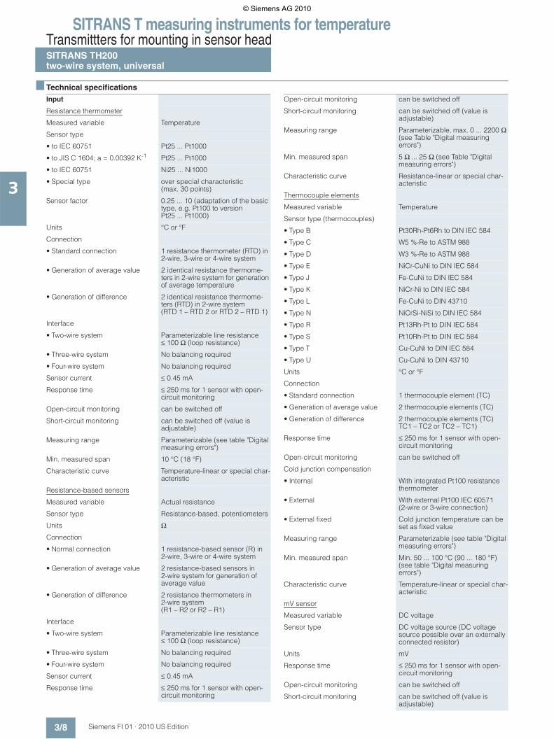
■ Technical specifications
Input
Resistance thermometer
Measured variable Temperature
Sensor type
• to IEC 60751 Pt25 ... Pt1000
• to JIS C 1604; a = 0.00392 K-1 Pt25 ... Pt1000
• to IEC 60751 Ni25 ... Ni1000
• Special type over special characteristic (max. 30 points)
Sensor factor 0.25 ... 10 (adaptation of the basic type, e.g. Pt100 to version Pt25 ... Pt1000)
Units °C or °F
Connection
• Standard connection 1 resistance thermometer (RTD) in 2-wire, 3-wire or 4-wire system
• Generation of average value 2 identical resistance thermome-ters in 2-wire system for generation of average temperature
• Generation of difference 2 identical resistance thermome-ters (RTD) in 2-wire system (RTD 1 – RTD 2 or RTD 2 – RTD 1)
Interface
• Two-wire system Parameterizable line resistance ≤ 100 Ω (loop resistance)
• Three-wire system No balancing required
• Four-wire system No balancing required
Sensor current ≤ 0.45 mA
Response time ≤ 250 ms for 1 sensor with open-circuit monitoring
Open-circuit monitoring can be switched off
Short-circuit monitoring can be switched off (value is adjustable)
Measuring range Parameterizable (see table "Digital measuring errors")
Min. measured span 10 °C (18 °F)
Characteristic curve Temperature-linear or special char-acteristic
Resistance-based sensors
Measured variable Actual resistance
Sensor type Resistance-based, potentiometers
Units Ω
Connection
• Normal connection 1 resistance-based sensor (R) in 2-wire, 3-wire or 4-wire system
• Generation of average value 2 resistance-based sensors in 2-wire system for generation of average value
• Generation of difference 2 resistance thermometers in 2-wire system (R1 – R2 or R2 – R1)
Interface
• Two-wire system Parameterizable line resistance ≤ 100 Ω (loop resistance)
• Three-wire system No balancing required
• Four-wire system No balancing required
Sensor current ≤ 0.45 mA
Response time ≤ 250 ms for 1 sensor with open-circuit monitoring
Open-circuit monitoring can be switched off
Short-circuit monitoring can be switched off (value is adjustable)
Measuring range Parameterizable, max. 0 ... 2200 Ω (see Table "Digital measuring errors")
Min. measured span 5 Ω ... 25 Ω (see Table "Digital measuring errors")
Characteristic curve Resistance-linear or special char-acteristic
Thermocouple elements
Measured variable Temperature
Sensor type (thermocouples)
• Type B Pt30Rh-Pt6Rh to DIN IEC 584
• Type C W5 %-Re to ASTM 988
• Type D W3 %-Re to ASTM 988
• Type E NiCr-CuNi to DIN IEC 584
• Type J Fe-CuNi to DIN IEC 584
• Type K NiCr-Ni to DIN IEC 584
• Type L Fe-CuNi to DIN 43710
• Type N NiCrSi-NiSi to DIN IEC 584
• Type R Pt13Rh-Pt to DIN IEC 584
• Type S Pt10Rh-Pt to DIN IEC 584
• Type T Cu-CuNi to DIN IEC 584
• Type U Cu-CuNi to DIN 43710
Units °C or °F
Connection
• Standard connection 1 thermocouple element (TC)
• Generation of average value 2 thermocouple elements (TC)
• Generation of difference 2 thermocouple elements (TC) TC1 – TC2 or TC2 – TC1)
Response time ≤ 250 ms for 1 sensor with open-circuit monitoring
Open-circuit monitoring can be switched off
Cold junction compensation
• Internal With integrated Pt100 resistance thermometer
• External With external Pt100 IEC 60571 (2-wire or 3-wire connection)
• External fixed Cold junction temperature can be set as fixed value
Measuring range Parameterizable (see table "Digital measuring errors")
Min. measured span Min. 50 ... 100 °C (90 ... 180 °F) (see table "Digital measuring errors")
Characteristic curve Temperature-linear or special char-acteristic
mV sensor
Measured variable DC voltage
Sensor type DC voltage source (DC voltage source possible over an externally connected resistor)
Units mV
Response time ≤ 250 ms for 1 sensor with open-circuit monitoring
Open-circuit monitoring can be switched off
Short-circuit monitoring can be switched off (value is adjustable)
© Siemens AG 2010

SITRANS T measuring instruments for temperatureTransmittters for mounting in sensor head
SITRANS TH200two-wire system, universal
3/9Siemens FI 01 · 2010 US Edition
3
Factory setting: • Pt100 (IEC 751) with three-wire circuit• Measuring range: 0 ... 100 °C (32 ... 212 °F)• Fault current: 22.8 mA• Sensor offset: 0 °C (0 °F)• Damping 0.0 s
Digital measuring errors
Resistance thermometer
Measuring range -10 ... +70 mV-100 ... +1100 mV
Min. measured span 2 mV or 20 mV
Overload capability of the input -1.5 ... +3.5 V DC
Input resistance ≥ 1 MΩ
Characteristic curve Voltage-linear or special character-istic
Output
Output signal 4 ... 20 mA, 2-wire
Auxiliary power supply 11 ... 35 V DC (to 30 V with EEx)
Max. load (Uaux – 11 V)/0.023 A
Overrange 3.6 ... 23 mA, infinitely adjustable (default range: 3.8 mA ... 20.50 mA)
Error signal (e.g. in the event of sen-sor breakage)
3.6 ... 23 mA, infinitely adjustable (default value: 22.8 mA)
Sample cycle 0.25 s nominal
Damping Software filter 1st order 0 ... 30 s (parameterizable)
Protection Against reversed polarity
Electrically isolated Input against output (1 kVeff)
Measuring accuracy
Digital measuring errors See Table "Digital measuring errors"
Reference conditions
• Auxiliary power supply 24 V ± 1 %
• Load 500 Ω
• Ambient temperature 23 °C
• Warming-up time > 5 min
Error in the analog output (digi-tal/analog converter)
< 0.025 % of span
Error due to internal cold junction < 0.5 °C (0.9 °F)
Temperature effect < 0.1 % of max. span/10 °C (18 °F)
Power supply effect < 0.001 % of span/V
Effect of load impedance < 0.002 % of span/100 Ω
Long-term drift
• in the first month < 0.02 % of max. span
• after one year < 0.2 % of max. span
• after 5 years < 0.3 % of max. span
Rated conditions
Ambient conditions
Ambient temperature range -40 ... +85 °C (-40 ... 185 °F)
Storage temperature range -40 ... +85 °C (-40 ... 185 °F)
Relative humidity < 98 %, with condensation
Electromagnetic compatibility acc. to EN 61326 and NE21
Design
Material Molded plastic
Weight 50 g (0.11 lb)
Dimensions See "Dimensional drawings"
Cross-section of cables Max. 2.5 mm² (AWG 13)
Degree of protection to IEC 60529
• Enclosure IP40
• Terminals IP00
Certificates and approvals
Explosion protection ATEX
EC type test certificate PTB 05 ATEX 2040X
• "Intrinsic safety" type of protection II 1 G Ex ia IIC T6/T4II 2 (1) G Ex ib/ia IIC T6/T4
• "Operating equipment that is non-ignitable and has limited energy" type of protection
II 3 G Ex nL IIC T6/T4II 3 G Ex nA IIC T6/T4
Explosion protection to FM for USA
• FM approval FM 3024169
• Degree of protection IS/Cl I, II, III/Div 1/GP ABCDEFG T6, T5, T4IS/Cl I/ZN 0/AEx ia IIC T6, T5, T4NI/Cl I, II, III/Div 2/GP ABCDFG T6, T5, T4NI/Cl I/ZN 2/IIC T6, T5, T4
Explosion protection to FM for Canada (cFMUS)
• FM approval FM 3024169C
• Degree of protection IS/Cl I/ZN 0/Ex ia IIC T6, T5, T4NI/Cl I/ZN 2/Ex nAL IIC T6, T5, T4
Software requirements for SIPROM T
PC operating system Windows ME, 2000 and XP; also Windows 95, 98 and 98 SE, but only in connection with RS 232 modem.
Input Measuring range Min. mea-sured span
Digital accuracy
°C (°F) °C (°F) °C (°F)
to IEC 60751
Pt25 -200 ... +850 (-328 ... +1562)
10 (18) 0,2 (0.36)
Pt50 -200 ... +850 (-328 ... +1562)
10 (18) 0,15 (0.27)
Pt100 ... Pt200 -200 ... +850 (-328 ... +1562)
10 (18) 0,1 (0.18)
Pt500 -200 ... +850 (-328 ... +1562)
10 (18) 0,15 (0.27)
Pt1000 -200 ... +350 (-328 ... +662)
10 (18) 0,15 (0.27)
to JIS C1604-81
Pt25 -200 ... +649 (-328 ... +1200)
10 (18) 0,2 (0.36)
Pt50 -200 ... +649 (-328 ... +1200)
10 (18) 0,15 (0.27)
Pt100 ... Pt200 -200 ... +649 (-328 ... +1200)
10 (18) 0,1 (0.18)
Pt500 -200 ... +649 (-328 ... +1200)
10 (18) 0,15 (0.27)
Pt1000 -200 ... +350 (-328 ... +662)
10 (18) 0,15 (0.27)
Ni 25 to Ni1000 -60 ... +250 (-76 ... +482)
10 (18) 0,1 (0.18)
© Siemens AG 2010

SITRANS T measuring instruments for temperatureTransmittters for mounting in sensor headSITRANS TH200two-wire system, universal
3/10 Siemens FI 01 · 2010 US Edition
3
Resistance-based sensors
Thermocouple elements
1) The digital accuracy in the range 0 to 300 °C (32 to 572 °F) is 3 °C (5.4 °F).2) The digital accuracy in the range 1750 to 2300 °C (3182 to 4172 °F) is
2 °C (3.6 °F).
mV sensor
The digital accuracy is the accuracy after the analog/digital con-version including linearization and calculation of the measured value.
An additional error is generated in the output current 4 to 20 mA as a result of the digital/analog conversion of 0.1 % of the set span (digital-analog error).
The total error under reference conditions at the analog output is the sum from the digital error and the digital-analog error (poss. with the addition of cold junction errors in the case of thermocou-ple measurements).
■ Selection and Ordering Data Order No.
C) Subject to export regulations AL: N, ECCN: EAR99.
Power supply units see "SITRANS I supply units and isolation amplifiers".
Factory setting: • Pt100 (IEC 751) with three-wire circuit• Measuring range: 0 ... 100 °C (32 ... 212 °F)• Fault current: 22.8 mA• Sensor offset: 0 °C (0 °F)• Damping 0.0 s
Input Measuring range
Min. measured span
Digital accuracy
Ω Ω Ω
Resistance 0 ... 390 5 0,05
Resistance 0 ... 2200 25 0,25
Input Measuring range
Min. measured span
Digital accuracy
°C(°F)
°C (°F) °C (°F)
Type B 0 ... 1820(32 ... 3308)
100 (180) 21) (3.60)1)
Type C (W5) 0 ... 2300(32 ... 4172)
100 (180) 2 (3.60)
Type D (W3) 0 ... 2300(32 ... 4172)
100 (180) 12) (1.80)2)
Type E -200 ... +1000(-328 ... +1832)
50 (90) 1 (1.80)
Type J -210 ... +1200(-346 ... +2192)
50 (90) 1 (1.80)
Type K -230 ... +1370(-382 ... +2498)
50 (90) 1 (1.80)
Type L -200 ... +900(-328 ... +1652)
50 (90) 1 (1.80)
Type N -200 ... +1300(-328 ... +2372)
50 (90) 1 (1.80)
Type R -50 ... +1760(-58 ... +3200)
100 (180) 2 (3.60)
Type S -50 ... +1760(-58 ... +3200)
100 (180) 2 (3.60)
Type T -200 ... +400(-328 ... +752)
40 (72) 1 (1.80)
Type U -200 ... +600(-328 ... +1112)
50 (90) 2 (3.60)
Input Measuring range
Min. measured span
Digital accuracy
mV mV μV
mV sensor -10 ... +70 2 40
mV sensor -100 ... +1100 20 400
Temperature transmitter SITRANS TH200
for installation in the connection head type B (DIN 43729) 2-wire connection 4 ... 20 mA, programmable, with electrical isolation
• Without explosion protection }
C)7NG3211-1NN00
• With explosion protection
- acc. to ATEX }
C)7NG3211-1AN00
- acc. to FM (cFMUS) }
C)7NG3211-1BN00
Further designs Order code
Please add "-Z" to Order No. and specify Order code(s)
Customer-specific setting of oper-ating data (specify operating data in plain text)
Y011)
1) Y01: Please specify all data that does not correspond to factory settings (see below).
with test protocol (5 measuring points)
C11
SIL 2 (functional safety) C20
Accessories Order No.
Modem for SITRANS TH100, TH200 and TR200 incl. SIPROM T parameterization software
• With USB connection }
C)7NG3092-8KU
• With RS 232 connection }
C)7NG3092-8KM
CD for measuring instruments for temperature
} A5E00364512
with documentation in German, English, French, Spanish, Italian, Portuguese and SIPROM T parameterization software
DIN rail adapters for head transmitters(Quantity delivered: 5 units)
} 7NG3092-8KA
4-wire connection cable150 mm, for sensor connections when using head transmitters in the high hinged cover (set with 5 units)
7NG3092-8KC
} Available ex stock.
© Siemens AG 2010

SITRANS T measuring instruments for temperatureTransmittters for mounting in sensor head
SITRANS TH200two-wire system, universal
3/11Siemens FI 01 · 2010 US Edition
3
■ Dimensional drawings
SITRANS TH200, dimensions and pin assignment, dimensions in mm (inch)
Mounting on DIN rail
SITRANS TH200, mounting of transmitter on DIN rail
DIN rail adaptor, dimensions in mm (inch)
1(+) and 2(-) Auxiliary power supply Uaux, output current IOut3, 4, 5 and 6 Pt100 sensor (for connections, see Sensor connection assignment)Test (+), Test (-) Measurement of the output current with a multimeter
(1) Test terminal(2) Mounting screw M4x30(3) LED for operation indication(4) Internal diameter of center hole 6.3 (0.25)
26,3
(1.0
4)
(1) (1)
(3)
(2)(2)
Ø 44 (1.73)
33 (1.30)
(4)
M4 x 30
50,5 (1.99)
59,6
(2.3
5)
33 (1.30)14 (0.55)
© Siemens AG 2010

SITRANS T measuring instruments for temperatureTransmittters for mounting in sensor headSITRANS TH200two-wire system, universal
3/12 Siemens FI 01 · 2010 US Edition
3
■ Schematics
SITRANS TH200, sensor connection assignment
Resistance thermometer Resistance Thermocouple
Current measurementVoltage measurement Connection of auxiliary power supply (Uaux)
Two-wire system 1)
Three-wire system
Four-wire system
Generation of average value / difference 1)
Two-wire system 1)
Three-wire system
Four-wire system
Generation of average value / difference 1)
Cold junction compensationInternal/fixed value
Cold junction compensation with external Pt100 in two-wire system 1)
Cold junction compensation with external Pt100 in three-wire system
Generation of average value / difference with internal cold junction compensation
1) Programmable line resistance for the purpose of correction.
Uaux+ -
© Siemens AG 2010

SITRANS T measuring instruments for temperatureTransmittters for mounting in sensor head
SITRANS TH300two-wire system, universal, HART
3/13Siemens FI 01 · 2010 US Edition
3
■ Overview
"HART" to beat - the universal SITRANS TH300 transmitter • Two-wire devices for 4 to 20 mA, HART• Mounting in the connection head of the temperature sensor• Universal input for virtually any type of temperature sensor• Configurable over HART
■ Benefits
• Compact design• Flexible mounting and center hole allow you to select your
preferred type of installation• Electrically isolated• Test sockets for multimeters• Diagnostics LED (green/red)• Sensor monitoring
open circuits and short-circuits• Self-monitoring• Configuration status stored in EEPROM• SIL 2 (with order code C20)• Expanded diagnostic functions, such as slave pointer, operat-
ing hours counter, etc.• Special characteristic• Electromagnetic compatibility to EN 61326 and NE21
■ Application
SITRANS TH300 transmitters can be used in all industrial sec-tors. Due to their compact size they can be installed in the con-nection head type B (DIN 43729) or larger. The following sen-sors/signal sources can be connected over their universal input module:• Resistance thermometers (two, three or four-wire system)• Thermocouple elements• Resistance-based sensors and DC voltage sources
The output signal is a direct current from 4 to 20 mA in accor-dance with the sensor characteristic, superimposed by the dig-ital HART signal.
Transmitters of the "intrinsically-safe" type of protection can be installed within potentially explosive atmospheres. The devices comply with the Directive 94/9/EC (ATEX), as well as FM and CSA regulations.
■ Function
The SITRANS TH300 is configured over HART. This can be done using a handheld communicator or even more conveniently with a HART modem and the SIMATIC PDM parameterization soft-ware. The configuration data are then permanently stored in the non-volatile memory (EEPROM).
Once the sensors and power supply have been correctly con-nected, the transmitter outputs a temperature-linear output sig-nal and the diagnostics LED displays a green light. In the case of a sensor short-circuit, the LED flashes red, an internal device fault is indicated by a steady red light.
The test socket can be used to connect an ammeter at any time for monitoring purposes and plausibility checks. The output cur-rent can be read without any interruption, or even without open-ing the current loop.
SITRANS TH 300 function diagram
InputA/D Analog-digital converterSensors Resistance thermometer, thermocouple, resistance-based sensor, mV sensorμC1 Microcontroller, secondary circuit
OutputμC2 Microcontroller, primary circuitD/A Digital-analog converterUaux Auxiliary power supplyIout Output current
(1) Electrically isolated(2) LED
TC/RTD sensor
(2)
+1
-2(1)μC1 μC2
Test
4 ... 20 mA Uaux, Iout
SITRANS TH200/TH300
DA
AD
© Siemens AG 2010

SITRANS T measuring instruments for temperatureTransmittters for mounting in sensor headSITRANS TH300two-wire system, universal, HART
3/14 Siemens FI 01 · 2010 US Edition
3
■ Technical specifications
Input
Resistance thermometer
Measured variable Temperature
Sensor type
• to IEC 60751 Pt25 ... Pt1000
• to JIS C 1604; a = 0.00392 K-1 Pt25 ... Pt1000
• to IEC 60751 Ni25 ... Ni1000
• Special type over special characteristic (max. 30 points)
Sensor factor 0.25 ... 10 (adaptation of the basic type, e.g. Pt100 to version Pt25 ... Pt1000)
Units °C or °F
Connection
• Standard connection 1 resistance thermometer (RTD) in 2-wire, 3-wire or 4-wire system
• Generation of average value 2 identical resistance thermome-ters in 2-wire system for generation of average temperature
• Generation of difference 2 identical resistance thermome-ters (RTD) in 2-wire system(RTD 1 – RTD 2 or RTD 2 – RTD 1)
Interface
• Two-wire system Parameterizable line resistance ≤ 100 Ω (loop resistance)
• Three-wire system No balancing required
• Four-wire system No balancing required
Sensor current ≤ 0.45 mA
Response time ≤ 250 ms for 1 sensor with open-circuit monitoring
Open-circuit monitoring can be switched off
Short-circuit monitoring can be switched off (value is adjustable)
Measuring range Parameterizable (see table "Digital measuring errors")
Min. measured span 10 °C (18 °F)
Characteristic curve Temperature-linear or special char-acteristic
Resistance-based sensors
Measured variable Actual resistance
Sensor type Resistance-based, potentiometers
Units Ω
Connection
• Normal connection 1 resistance-based sensor (R) in 2-wire, 3-wire or 4-wire system
• Generation of average value 2 resistance-based sensors in 2-wire system for generation of average value
• Generation of difference 2 resistance thermometers in 2-wire system (R1 – R2 or R2 – R1)
Interface
• Two-wire system Parameterizable line resistance ≤ 100 Ω (loop resistance)
• Three-wire system No balancing required
• Four-wire system No balancing required
Sensor current ≤ 0.45 mA
Response time ≤ 250 ms for 1 sensor with open-circuit monitoring
Open-circuit monitoring can be switched off
Short-circuit monitoring can be switched off (value is adjustable)
Measuring range Parameterizable, max. 0 ... 2200 Ω (see Table "Digital measuring errors")
Min. measured span 5 ... 25 Ω (see Table "Digital measuring errors")
Characteristic curve Resistance-linear or special characteristic
Thermocouples
Measured variable Temperature
Sensor type (thermocouples)
• Type B Pt30Rh-Pt6Rh to DIN IEC 584
• Type C W5 %-Re to ASTM 988
• Type D W3 %-Re to ASTM 988
• Type E NiCr-CuNi to DIN IEC 584
• Type J Fe-CuNi to DIN IEC 584
• Type K NiCr-Ni to DIN IEC 584
• Type L Fe-CuNi to DIN 43710
• Type N NiCrSi-NiSi to DIN IEC 584
• Type R Pt13Rh-Pt to DIN IEC 584
• Type S Pt10Rh-Pt to DIN IEC 584
• Type T Cu-CuNi to DIN IEC 584
• Type U Cu-CuNi to DIN 43710
Units °C or °F
Connection
• Standard connection 1 thermocouple (TC)
• Generation of average value 2 thermocouples (TC)
• Generation of difference 2 thermocouples (TC) TC1 – TC2 or TC2 – TC1)
Response time ≤ 250 ms for 1 sensor with open-circuit monitoring
Open-circuit monitoring can be switched off
Cold junction compensation
• Internal With integrated Pt100 resistance thermometer
• External With external Pt100 IEC 60571 (2-wire or 3-wire connection)
• External fixed Cold junction temperature can be set as fixed value
Measuring range Parameterizable(see table "Digital measuring errors")
Min. measured span Min. 50 ... 199 °C (90 ... 180 °F) (see table "Digital measuring errors")
Characteristic curve Temperature-linear or special characteristic
mV sensor
Measured variable DC voltage
Sensor type DC voltage source (DC voltage source possible over an externally connected resistor)
Units mV
Response time ≤ 250 ms for 1 sensor with open-circuit monitoring
Open-circuit monitoring can be switched off
© Siemens AG 2010

SITRANS T measuring instruments for temperatureTransmittters for mounting in sensor head
SITRANS TH300two-wire system, universal, HART
3/15Siemens FI 01 · 2010 US Edition
3
Factory setting: • Pt100 (IEC 751) with three-wire circuit• Measuring range: 0 ... 100 °C (32 ... 212 °F)• Fault current: 22.8 mA• Sensor offset: 0 °C (0 °F)• Damping 0.0 s
Digital measuring errors
Resistance thermometer
Short-circuit monitoring can be switched off (value is adjustable)
Measuring range -10 ... +70 mV-100 … +1100 mV
Min. measured span 2 mV or 20 mV
Overload capacity of the input -1.5 ... +3.5 V DC
Input resistance ≥ 1 MΩ
Characteristic curve Voltage-linear or special character-istic
Output
Output signal 4 ... 20 mA, 2-wire with communi-cation to HART Rev. 5.9
Auxiliary power supply 11 ... 35 V DC (to 30 V with EEx)
Max. load (Uaux – 11 V)/0.023 A
Overrange 3.6 ... 23 mA, continuously adjust-able (default range: 3.8 mA ... 20.50 mA)
Error signal (e.g. in the event ofsensor breakage)
3.6 ... 23 mA, continuously adjust-able (default value: 22.8 mA)
Sample cycle 0.25 s nominal
Damping Software filter 1st order 0 ... 30 s (parameterizable)
Protection Against reversed polarity
Electrically isolated Input against output (1 kVeff)
Measuring accuracy
Digital measuring errors See Table "Digital measuring errors"
Reference conditions
• Auxiliary power supply 24 V ± 1 %
• Load 500 Ω
• Storage temperature 23 °C
• Warming-up time > 5 min
Error in the analog output (digital/analog converter)
< 0.025 % of span
Error due to internal cold junction < 0.5 °C (0.9 °F)
Temperature effect < 0.1 % of max. span/10 °C (18 °F)
Power supply effect < 0.001 % of span/V
Effect of load impedance < 0.002 % of span/100 Ω
Long-term drift
• in the first month < 0.02 % of max. span
• after one year < 0.2 % of max. span
• after 5 years < 0.3 % of max. span
Rated conditions
Ambient temperature
Ambient temperature range -40 ... +85 °C (-40 ... 185 °F)
Storage temperature range -40 ... +85 °C (-40 ... 185 °F)
Relative humidity < 98 %, with condensation
Electromagnetic compatibility acc. to EN 61326 and NE21
Construction
Material Molded plastic
Weight 50 g (0.11 lb)
Dimensions See "Dimensional drawings"
Cross-section of cables Max. 2.5 mm² (AWG 13)
Degree of protection to IEC 60529
• Enclosure IP40
• Terminals IP00
Certificate and approvals
Explosion protection ATEX
EC type test certificate PTB 05 ATEX 2040X
• "Intrinsic safety" type of protection
II 1 G Ex ia IIC T6/T4II 2 (1) G Ex ib/ia IIC T6/T4
• "Operating equipment that is non-ignitable and has limited energy" type of protection
II 3 G Ex nL IIC T6/T4II 3 G Ex nA IIC T6/T4
Explosion protection to FM for USA
• FM approval FM 3024169
• Degree of protection IS/Cl I, II, III/Div 1/GP ABCDEFG T6, T5, T4IS/Cl I/ZN 0/AEx ia IIC T6, T5, T4NI/Cl I, II, III/Div 2,GP ABCDFG T6, T5, T4NI/Cl I/ZN 2/IIC T6, T5, T4
Explosion protection to FM for Canada (cFMUS)
• FM approval FM 3024169C
• Degree of protection IS/Cl I/ZN 0/Ex ia IIC T6, T5, T4NI/Cl I/ZN 2/Ex nAL IIC T6, T5, T4
Input Measuring range Min. mea-sured span
Digital accu-racy
°C (°F) °C (°F) °C (°F)
to IEC 60751
Pt25 -200 ... +850 (-328 ... +1562)
10 (18) 0.2 (0.36)
Pt50 -200 ... +850 (-328 ... +1562)
10 (18) 0.15 (0.27)
Pt100 ... Pt200 -200 ... +850 (-328 ... +1562)
10 (18) 0.1 (0.18)
Pt500 -200 ... +850 (-328 ... +1562)
10 (18) 0.15 (0.27)
Pt1000 -200 ... +350 (-328 ... +662)
10 (18) 0.15 (0.27)
to JIS C1604-81
Pt25 -200 ... +649 (-328 ... +1200)
10 (18) 0.2 (0.36)
Pt50 -200 ... +649 (-328 ... +1200)
10 (18) 0.15 (0.27)
Pt100 ... Pt200 -200 ... +649 (-328 ... +1200)
10 (18) 0.1 (0.18)
Pt500 -200 ... +649 (-328 ... +1200)
10 (18) 0.15 (0.27)
Pt1000 -200 ... +350 (-328 ... +662)
10 (18) 0.15 (0.27)
Ni 25 to Ni1000 -60 ... +250 (-76 ... +482)
10 (18) 0.1 (0.18)
© Siemens AG 2010

SITRANS T measuring instruments for temperatureTransmittters for mounting in sensor headSITRANS TH300two-wire system, universal, HART
3/16 Siemens FI 01 · 2010 US Edition
3
Resistance-based sensors
Thermocouple elements
1) The digital accuracy in the range 0 to 300 °C (32 to 572 °F) is 3 °C (5.4 °F).2) The digital accuracy in the range 1750 to 2300 °C (3182 to 4172 °F) is
2 °C (3.6 °F).
mV sensor
The digital accuracy is the accuracy after the analog/digital con-version including linearization and calculation of the measured value.
An additional error is generated in the output current 4 to 20 mA as a result of the digital/analog conversion of 0.1 % of the set span (digital-analog error).
The total error under reference conditions at the analog output is the sum from the digital error and the digital-analog error (poss. with the addition of cold junction errors in the case of thermocou-ple measurements).
■ Selection and Ordering Data Order No.
C) Subject to export regulations AL: N, ECCN: EAR99.D) Subject to export regulations AL: N, ECCN: EAR99H.
Power supply units see "SITRANS I supply units and isolation amplifiers".
Factory setting: • Pt100 (IEC 751) with three-wire circuit• Measuring range: 0 ... 100 °C (32 ... 212 °F)• Fault current: 22.8 mA• Sensor offset: 0 °C (0 °F)• Damping 0.0 s
Input Measuring range
Min. measured span
Digital accu-racy
Ω Ω Ω
Resistance 0 ... 390 5 0.05
Resistance 0 ... 2200 25 0.25
Input Measuring range
Min. measured span
Digital accuracy
°C (°F) °C (°F) °C (°F)
Type B 0 ... 1820(32 ... 3308)
100 (180) 21) (3.60)1)
Type C (W5) 0 ... 2300(32 ... 4172)
100 (180) 2 (3.60)
Type D (W3) 0 ... 2300(32 ... 4172)
100 (180) 12) (1.80)2)
Type E -200 ... +1000(-328 ... +1832)
50 (90) 1 (1.80)
Type J -210 ... +1200(-346 ... +2192)
50 (90) 1 (1.80)
Type K -230 ... +1370(-382 ... +2498)
50 (90) 1 (1.80)
Type L -200 ... +900(-328 ... +1652)
50 (90) 1 (1.80)
Type N -200 ... +1300(-328 ... +2372)
50 (90) 1 (1.80)
Type R -50 ... +1760(-58 ... +3200)
100 (180) 2 (3.60)
Type S -50 ... +1760(-58 ... +3200)
100 (180) 2 (3.60)
Type T -200 ... +400(-328 ... +752)
40 (72) 1 (1.80)
Type U -200 ... +600(-328 ... +1112)
50 (90) 2 (3.60)
Input Measuring range
Min. measured span
Digital accuracy
mV mV μV
mV sensor -10 ... +70 2 40
mV sensor -100 ... +1100 20 400
Temperature transmitter SITRANS TH300
for installation in the connection head type B (DIN 43729) 2-wire connection 4 ... 20 mA, communication-capable acc. to HART, with electrical isolation
• Without explosion protection }
C)7NG3212-0NN00
• With explosion protection
- acc. to ATEX }
C)7NG3212-0AN00
- acc. to FM (cFMUS) }
C)7NG3212-0BN00
Further designs Order code
Please add "-Z" to Order No. and specify Order code(s)
Customer-specific setting of oper-ating data (specify operating data in plain text)
Y011)
1) Y01: Please specify all data that does not correspond to factory settings (see below).
with test protocol (5 measuring points)
C11
SIL 2 (functional safety) C20
Accessories Order No.
CD for measuring instruments for temperature
} A5E00364512
with documentation in German, English, French, Spanish, Italian, Portuguese and SIPROM T parameterization software
HART modem
• With RS 232 connection }
D)7MF4997-1DA
• With USB connection }
D)7MF4997-1DB
SIMATIC PDM operating software
See Section 9
DIN rail adapters for head transmitters(Quantity delivered: 5 units)
} 7NG3092-8KA
4-wire connection cable150 mm, for sensor connections when using head transmitters in the high hinged cover (set with 5 units)
7NG3092-8KC
} Available ex stock.
© Siemens AG 2010

SITRANS T measuring instruments for temperatureTransmittters for mounting in sensor head
SITRANS TH300two-wire system, universal, HART
3/17Siemens FI 01 · 2010 US Edition
3
■ Dimensional drawings
SITRANS TH300, dimensions and pin assignment,dimensions in mm (inch)
Mounting on DIN rail
SITRANS TH300, mounting of transmitter on DIN rail
DIN rail adapter, dimensions in mm (inch)
1(+) and 2(-) Auxiliary power supply Uaux, output current IOut3, 4, 5 and 6 Pt100 sensor (for connections, see Sensor connection assignment)Test (+), Test (-) Measurement of the output current with a multimeter
(1) Test terminal(2) Mounting screw M4x30(3) LED for operation indication(4) Internal diameter of center hole 6.3 (0.25)
26,3
(1.0
4)
(1) (1)
(3)
(2)(2)
Ø 44 (1.73)
33 (1.30)
(4)
M4 x 30
50,5 (1.99)
59,6
(2.3
5)
33 (1.30)14 (0.55)
© Siemens AG 2010

SITRANS T measuring instruments for temperatureTransmittters for mounting in sensor headSITRANS TH300two-wire system, universal, HART
3/18 Siemens FI 01 · 2010 US Edition
3
■ Schematics
SITRANS TH200/TH300, sensor connection assignment
Resistance thermometer Resistance Thermocouple
Current measurementVoltage measurement Connection of auxiliary power supply (Uaux)
Two-wire system 1)
Three-wire system
Four-wire system
Generation of average value / difference 1)
Two-wire system 1)
Three-wire system
Four-wire system
Generation of average value / difference 1)
Cold junction compensationInternal/fixed value
Cold junction compensation with external Pt100 in two-wire system 1)
Cold junction compensation with external Pt100 in three-wire system
Generation of average value / difference with internal cold junction compensation
1) Programmable line resistance for the purpose of correction.
Uaux+ -
© Siemens AG 2010

SITRANS T measuring instruments for temperatureTransmittters for mounting in sensor head
SITRANS TH400fieldbus transmitter
3/19Siemens FI 01 · 2010 US Edition
3
■ Overview
SITRANS TH400 fieldbus transmitters
Versions:• for FOUNDATION Fieldbus and• for PROFIBUS PA
The SITRANS TH400 temperature transmitter is a small field bus transmitter for mounting in the connection head of form B. Exten-sive functionality enables the temperature transmitter to be pre-cisely adapted to the plant’s requirements. Operation is very simple in spite of the numerous setting options. Thanks to its uni-versal concept it can be used in all industries and is easy to in-tegrate in Totally Integrated Automation applications.
Transmitters of the "intrinsically-safe" type of protection can be installed within potentially explosive atmospheres. The devices comply with the Directive 94/9/EC (ATEX), as well as FM and CSA regulations.
Installing SITRANS TH400 in temperature sensors turns them into complete, bus-capable measuring points; compact - and in a single device.
■ Application
• Linearized temperature measurement with resistance thermometers or thermocouple elements
• Differential, mean-value or redundant temperature measure-ment with resistance thermometers or thermocouple elements
• Linear resistance and bipolar millivolt measurements• Differential, mean-value or redundant resistance and bipolar
millivolt measurements
■ Function
Features
common• Mounting in connection head, type B, to DIN 43729, or larger• Polarity-neutral bus connection• 24-bit analog-digital converter for high resolution• Electrically isolated• Intrinsically-safe version for use in potentially explosive areas• Special characteristic• Sensor redundance
Transmitter with PROFIBUS PA communication• Function blocks: 2 x analog
Transmitter with FOUNDATION Fieldbus communication• Function blocks: 2 x analog and 1 x PID• Functionality: Basic or LAS
Mode of operation
The following function plan explains the mode of operation of the transmitter.
The only difference between the two versions of the SITRANS TH400 (7NG3214-... and 7NG3215-...) is the type of fieldbus protocol used (PROFIBUS PA or FOUNDATION fieldbus).
SITRANS TH400, function diagram
Optional inputs:- Resistance thermometer- Thermocouple- mV sensor- Resistance-based sensors
Input 1
Input 2
TransformerInput 1Input 2DifferentialMean valueRedundancyTerminal temperatureEngineering units Diagnostic functionsTable linearizationPolynomial linearizationProcess calibration
A/D converter
Complex configurationCorrection coefficientFactory settings
- PROFIBUS protocol (7NG3214) or- Foundation Fieldbus protocol (7NG3215)
Bus connection
Ex
pow
er c
ircui
t
Electrically isolated
Internal Pt100
Communication
EEPROM
CPU
6
5
4
32
1
© Siemens AG 2010

SITRANS T measuring instruments for temperatureTransmittters for mounting in sensor headSITRANS TH400fieldbus transmitter
3/20 Siemens FI 01 · 2010 US Edition
3
System communication
SITRANS TH400, communication interface
■ Technical specifications
Input
Analog-to-digital conversion
• Measurement rate < 50 ms
• Resolution 24 Bit
Resistance thermometer
Pt25 ... Pt1000 to IEC 60751/JIS C 1604
• Measuring range -200 ... +850 °C(-328 ... +1562 °F)
Ni25 ... Ni1000 to DIN 43760
• Measuring range -60 ... +250 °C(-76 ... +482 °F)
Cu10 ... Cu1000, α = 0,00427
• Measuring range -50 ... +200 °C(-58 ... +392 °F)
Line resistance per sensor cable Max. 50 Ω
Sensor current Nominal 0.2 mA
Sensor fault detection
• Sensor break detection Yes
• Sensor short-circuit detection Yes, < 15 Ω
Resistance-based sensors
Measuring range 0 Ω... 10 kΩ
Line resistance per sensor cable Max. 50 Ω
Sensor current Nominal 0.2 mA
Sensor fault detection
• Sensor break detection Yes
• Sensor short-circuit detection Yes, < 15 Ω
s
s
Output:
Bus terminator
Bus terminator
Segment coupler
Segment coupler
Bus connection
Bus connection
PROFIBUS PA
FOUNDATION Fieldbus
SITRANS TH400 FF
SITRANS TH400 PA
12
12
Thermocouple
to IEC 584 Measuring range
• Type B 400 ... 1820 °C (+752 ... +3308 °F)
• Type E -100 ... +1000 °C (-148 ... +1832 °F)
• Type J -100 ... +1000 °C (-148 ... +1832 °F)
• Type K -100 ... +1200 °C (-148 ... +2192 °F)
• Type N -180 ... +1300 °C (-292 ... +2372 °F)
• Type R -50 ... +1760 °C (-58 ... +3200 °F)
• Type S -50 ... +1760 °C (-58 ... +3200 °F)
• Type T -200 ... +400 °C (-328 ... +752 °F)
to DIN 43710
• Type L -200 ... +900 °C (-328 ... +1652 °F)
• Type U -200 ... +600 °C (-328 ... +1112 °F)
to ASTM E988-90
• Type W3 0 ... 2300 °C (+32 ... +4172 °F)
• Type W5 0 ... 2300 °C (+32 ... +4172 °F)
External cold junction compensation -40 ... +135 °C (-40 ... +275 °F)
Sensor fault detection
• Sensor break detection Yes
• Sensor short-circuit detection Yes, < 3 mV
• Sensor current in the event of open-circuit monitoring
4 μA
mV sensor - voltage input
Measuring range -800 ... +800 mV
Input resistance 10 MΩ
Output
Filter time (programmable) 0 ... 60 s
Update time < 400 ms
Measuring accuracy
Accuracy is defined as the higher value of general values and basic values.
General values
Type of input Absoluteaccuracy
Temperature coefficient
All ≤ ±0,05 % of measured value
≤ ±0,002 % of measured value/°C
Basic values
Type of input Basic accuracy Temperature coefficient
Pt100 and Pt1000 ≤ ±0.1 °C ≤ ±0.002 °C/°C
Ni100 ≤ ±0.15 °C ≤ ±0.002 °C/°C
Cu10 ≤ ±1.3 °C ≤ ±0.02 °C/°C
Resistance-based sensors ≤ ±0.05 Ω ≤ ±0.002 Ω/°C
Voltage source ≤ ±10 μV ≤ ±0.2 μV/°C
Thermal element, type:E, J, K, L, N, T, U
≤ ±0.5 °C ≤ ±0.01 °C/°C
Thermal element, type:B, R, S, W3, W5
≤ ±1 °C ≤ ±0.025 °C/°C
Cold junction compensation ≤ ±0.5 °C
Reference conditions
Warming-up time 30 s
Signal-to-noise ratio Min. 60 dB
Calibration condition 20 ... 28 °C (68 ... 82 °F)
© Siemens AG 2010

SITRANS T measuring instruments for temperatureTransmittters for mounting in sensor head
SITRANS TH400fieldbus transmitter
3/21Siemens FI 01 · 2010 US Edition
3
Rated conditions
Ambient temperature
Permissible ambient temperature -40 ... +85 °C (-40 ... +185 °F)
Permissible storage temperature -40 ... +85 °C (-40 ... +185 °F)
Relative humidity ≤ 98 %, with condensation
Electrically isolated
• without Ex Input against output1 kVeff
• with Ex Input against output 500 Veff
Mechanical testing
• Vibrations (DIN class B) to IEC 60068-2-6 and IEC 60068-2-644 g/2 ... 100 Hz
Electromagnetic compatibility
EMC noise voltage influence < ±0,1 % of span
Extended EMC noise immunity:NAMUR NE 21, criterion A, Burst
< ±1 % of span
EMC 2004/108/EC Emission and Noise Immunity to
EN 61326
Design
Material Molded plastic
Weight 55 g (0.12 lb)
Dimensions See "Dimensional drawings"
Cross-section of cables Max. 2.5 mm² (AWG 13)
Degree of protection
• Transmitter enclosure IP40
• Terminal IP00
Auxiliary power supply
Power supply
• Standard, Ex nA, Ex nL and NI DC 9.0 ... 32 V
• ATEX, FM, UL and CSA DC 9.0 ... 30 V
• In FISCO/FNICO installation DC 9.0 ... 17.5 V
Power consumption < 11 mA
Max. increase in power consump-tion in the event of a fault
< 7 mA
Certificate and approvals
Explosion protection ATEX
EC type test certificate KEMA 06 ATEX 0264 X
• "Intrinsic safety" type of protection II 1 GD EEx ia IIC T4 ... T6 T65 °C ... T105 °CII 2(1) GD EEx ib [ia] IIC T4 ... T6 T65 °C ... T105 °C
EC type test certificate KEMA 06 ATEX 0263 X
• "Operating equipment that is non-ignitable“ type of protection
II 3 G EEx nA[nL] IIC T4 ... T6II 3 G EEx nL IIC T4 ... T6
Explosion protection FM for USA
• FM approval FM 3027985
• Degree of protection • IS/Cl I/Div 1/Groups ABCDT4, T5, T6, FISCO
• IS/Cl I/ZN 0/AEx ia, IIC T4, T5, T6, FISCO
• NI/Cl I/Div 2/Groups ABCDT4, T5, T6, FNICO
Explosion protection CSA for Canada
• CSA approval CSA 1861385
• Degree of protection • IS/Cl I/Groups ABCD T4, T5, T6• Ex ia IIC T4/T5/T6
Ex ib [ia] IIC T4/T5/T6• Cl I/Div 2/Groups ABCD
T4, T5, T6• Ex nA IIC T4/T5/T6
CI I/ZN 2/ AEx nA II T4, T5, T6
Communication
Parameterization interface
• PROFIBUS PA connection
- Protocol Profile 3.0
- Address (for delivery) 126
• FOUNDATION Fieldbus connec-tion
- Protocol FF Protocoll
- Functionality Basic or LAS
- Version ITK 4.6
- Function blocks 2 x Analog and 1 x PID
Factory setting for SITRANS TH400 PA and SITRANS TH400 FF
Sensor Pt100 (IEC)
Type of connection Three-wire system
Unit °C
Failure mode Last valid value
Filter time 0 s
only for SITRANS TH400 PA
PA address 126
PROFIBUS Ident No. Manufacturer-specific
only for SITRANS TH400 FF
Node address 22
© Siemens AG 2010

SITRANS T measuring instruments for temperatureTransmittters for mounting in sensor headSITRANS TH400fieldbus transmitter
3/22 Siemens FI 01 · 2010 US Edition
3
Factory setting: • for SITRANS TH400 PA:
- Pt100 (IEC 751) with three-wire circuit- Unit: °C- Failure mode: Last valid value- Filter time: 0 s- PA address: 126- PROFIBUS Ident No.: Manufacturer-specific
• for SITRANS TH400 FF:- Pt100 (IEC 751) with three-wire circuit- Unit: °C- Failure mode: Last valid value- Filter time: 0 s- Node address: 22
■ Dimensional drawings
SITRANS TH400 dimensions in mm (inches) and connections
Mounting on DIN rail
SITRANS TH400, mounting of transmitter on DIN rail
DIN rail adapter, dimensions in mm (inch)
Selection and Ordering data Order No.
Temperature transmitter SITRANS TH400for installation in the sensor head, with electrical isolation, order instruction man-ual separately.
• Bus-capable to PROFIBUS PA
- without explosion protection or EEx n or NI
}
C)7NG3214-0NN00
- with explosion protection „intrinsicsafety to ATEX/FM/CSA“
}
C)7NG3214-0AN00
• Bus-capable to FOUNDATION Fieldbus
- without explosion protection or EEx nor NI
}
C)7NG3215-0NN00
- with explosion protection „intrinsicsafety to ATEX/FM/CSA“
}
C)7NG3215-0AN00
Further designs Order codePlease add „-Z“ to Order No. and specifiy Order code (s) and plain text.
• Customer-specific setting of operating data (specify in plain text)
Y01 1)
1) Y01: Please specify all data that does not correspond to factory settings (see below).
• With test protocol (5 measuring points) C11 2)
2) Can only be ordered together with Y01 (it is essential to specify the mea-suring range).
C) Subject to export regulations AL: N, ECCN: EAR99.
Accessories Order No.
CD for measuring instruments for temperature
} A5E00364512
with documentation in German, English, French, Spanish, Italian, Portuguese and SIPROM T parameterization software
SIMATIC PDM operating software see chapter 9
DIN rail adapters for head transmitters(Quantity delivered: 5 units)
7NG3092-8KA
4-wire connection cable150 mm, for sensor connections when using head transmitters in the high hinged cover (set with 5 units)
7NG3092-8KC
For additional PA components see catalog IK PI
} Available ex stock.
Terminals 1, 2: Fieldbus connectionTerminals 3 ... 6: Sensor connection
26,3 (1.04)33 (1.3)
Ø 44 (1.73)
Ø 6,3 (0.25)
M4 x 30
s1 2
54
3 6
+ -3-W
50,5 (1.99)
59,6
(2.3
5)
33 (1.30)14 (0.55)
© Siemens AG 2010

SITRANS T measuring instruments for temperatureTransmittters for mounting in sensor head
SITRANS TH400fieldbus transmitter
3/23Siemens FI 01 · 2010 US Edition
3
■ Schematics
SITRANS TH400, sensor connection assignment
Resistance thermometer ResistanceThermocouple
Voltage measurement
Two-wire system 1)
Three-wire system
Four-wire system
Two-wire system 1)
Three-wire system
Four-wire system
Internal cold junction compensation
Cold junction compensation with external Pt100 in two-wire system 1)
Cold junction compensation with external Pt100 in three-wire system
1) Programmable line resistance for the purpose of correction.
Mean-value/differential or redundancy generation
1 sensor in two-wire system 1)
1 sensor in three-wire system
Mean-value/differential or redundancy generation2 x two-wire system 1)
Mean value, differential or redundancy generation with internal
cold junction compensation
Mean value, differential or redundancy generation and cold junction compensation
with internal Pt100 in two-wire system 1)
Mean value, differential or redundancy generation1 resistor in two-wire system 1)
1 resistor in three-wire system
Measurement of mean value, differential and redundancy with 2 voltage sources
One voltage source
12
12
+ -
+ -
+ -
12
+ -
12
+ - + -
21+ -
+ -
12
+ -+ -
© Siemens AG 2010

SITRANS T measuring instruments for temperatureTransmitters for rail mountingSITRANS TR200two-wire system, universal
3/24 Siemens FI 01 · 2010 US Edition
3
■ Overview
Ultra flexible - with the universal SITRANS TR200 transmitter • Two-wire devices for 4 to 20 mA• Enclosure for rail mounting• Universal input for virtually any type of temperature sensor • Configurable over PC
■ Benefits
• Compact design• Electrically isolated• Test sockets for multimeters• Diagnostics LED (green/red)• Sensor monitoring
open circuits and short-circuits• Self-monitoring• Configuration status stored in EEPROM• Expanded diagnostic functions, such as slave pointer,
operating hours counter, etc.• Special characteristic• Electromagnetic compatibility to EN 61326 and NE21• SIL 2 (with order code C20)
■ Application
SITRANS TR200 transmitters can be used in all industrial sec-tors. Their compact design enables simple mounting on stan-dard DIN rails on-site in protective boxes or in control cabinets. The following sensors/signal sources can be connected over their universal input module:• Resistance thermometers (two, three or four-wire system)• Thermocouple elements• Resistance-based sensors and DC voltage sources
The output signal is a direct current from 4 to 20 mA in accor-dance with the sensor characteristic.
Transmitters of the "intrinsically-safe" type of protection can be installed within potentially explosive atmospheres. The devices comply with the Directive 94/9/EC (ATEX).
■ Function
The SITRANS TR200 is configured over a PC. A USB or RS 232 modem is linked to the output terminals for this purpose. The configuration data can now be edited using the SIPROM T soft-ware tool. The configuration data are then permanently stored in the non-volatile memory (EEPROM).
Once the sensors and power supply have been correctly con-nected, the transmitter outputs a temperature-linear output sig-nal and the diagnostics LED displays a green light. In the case of a sensor short-circuit, the LED flashes red, an internal device fault is indicated by a steady red light.
The test socket can be used to connect an ammeter at any time for monitoring purposes and plausibility checks. The output cur-rent can be read without any interruption, or even without open-ing the current loop.
SITRANS TR200 function diagram
1 Sensor such as resistance thermometer, thermocouple, resistance-based, sensor, mV sensor2 Analog-digital converter3 Microcontroller, secondary circuit
4 Electrical isolation5 Microcontroller, primary circuit6 Digital-analog converter7 LED
Uaux Auxiliary power supplyIout Output currentTest Test terminals for temporary connection of an amperemeter
SensorTC/RTD
A
D
D
AμC1 μC2
Test
4 ... 20 mA Uaux, Iout
SITRANS TR200/TR300
17
6
3
45
2
© Siemens AG 2010

SITRANS T measuring instruments for temperatureTransmitters for rail mounting
SITRANS TR200two-wire system, universal
3/25Siemens FI 01 · 2010 US Edition
3
■ Technical specifications
Input
Resistance thermometer
Measured variable Temperature
Sensor type
• to IEC 60751 Pt25 ... Pt1000
• to JIS C 1604; a=0.00392 K-1 Pt25 ... Pt1000
• to IEC 60751 Ni25 ... Ni1000
• Special type Over special characteristic (max. 30 points)
Sensor factor 0.25 ... 10 (adaptation of the basic type, e.g. Pt100 to version Pt25 ... Pt1000)
Units °C or °F
Connection
• Standard connection 1 resistance thermometer (RTD) in 2-wire, 3-wire or 4-wire system
• Generation of average value 2 identical resistance thermome-ters in 2-wire system for generation of average temperature
• Generation of difference 2 identical resistance thermome-ters (RTD) in 2-wire system (RTD 1 – RTD 2 or RTD 2 – RTD 1)
Interface
• Two-wire system Parameterizable line resistance ≤ 100 Ω (loop resistance)
• Three-wire system No balancing required
• Four-wire system No balancing required
Sensor current ≤ 0.45 mA
Response time T63 ≤ 250 ms for 1 sensor with open-circuit monitoring
Open-circuit monitoring Always active (cannot be disabled)
Short-circuit monitoring Can be switched off (value is adjustable)
Measuring range Parameterizable (see table "Digital measuring errors")
Min. measured span 10 °C (18 °F)
Characteristic curve Temperature-linear or special characteristic
Resistance-based sensors
Measured variable Actual resistance
Sensor type Resistance-based, potentiometers
Units Ω
Connection
• Normal connection 1 resistance-based sensor (R) in 2-wire, 3-wire or 4-wire system
• Generation of average value 2 resistance-based sensors in 2-wire system for generation of average value
• Generation of difference 2 resistance thermometers in 2-wire system (R1 – R2 or R2 – R1)
Interface
• Two-wire system Parameterizable line resistance ≤ 100 Ω (loop resistance)
• Three-wire system No balancing required
• Four-wire system No balancing required
Sensor current ≤ 0.45 mA
Response time T63 ≤ 250 ms for 1 sensor with open-circuit monitoring
Open-circuit monitoring Always active (cannot be disabled)
Short-circuit monitoring Can be switched off (value is adjustable)
Measuring range Parameterizable, max. 0 ... 2200 Ω (see Table "Digital measuring errors")
Min. measured span 5 ... 25 Ω (see Table "Digital mea-suring errors")
Characteristic curve Resistance-linear or special char-acteristic
Thermocouple elements
Measured variable Temperature
Sensor type (thermocouples)
• Type B Pt30Rh-Pt6Rh to DIN IEC 584
• Type C W5 %-Re to ASTM 988
• Type D W3 %-Re to ASTM 988
• Type E NiCr-CuNi to DIN IEC 584
• Type J Fe-CuNi to DIN IEC 584
• Type K NiCr-Ni to DIN IEC 584
• Type L Fe-CuNi to DIN 43710
• Type N NiCrSi-NiSi to DIN IEC 584
• Type R Pt13Rh-Pt to DIN IEC 584
• Type S Pt10Rh-Pt to DIN IEC 584
• Type T Cu-CuNi to DIN IEC 584
• Type U Cu-CuNi to DIN 43710
Units °C or °F
Connection
• Standard connection 1 thermocouple element (TC)
• Generation of average value 2 identical thermocouple elements (TC)
• Generation of difference 2 identical thermocouple elements (TC) TC1 – TC2 or TC2 – TC1
Response time T63 ≤ 250 ms for 1 sensor with open-circuit monitoring
Open-circuit monitoring Can be switched off
Cold junction compensation
• Internal With integrated Pt100 resistance thermometer
• External With external Pt100 IEC 60571 (2-wire or 3-wire connection)
• External fixed Cold junction temperature can be set as fixed value
Measuring range Parameterizable (see table "Digital measuring errors")
Min. measured span Min. 50 ... 100 °C (90 ... 180 °F) (see table "Digital measuring errors")
Characteristic curve Temperature-linear or specialcharacteristic
mV sensor
Measured variable DC voltage
Sensor type DC voltage source (DC voltage source possible over an externally connected resistor)
Units mV
Response time T63 ≤ 250 ms for 1 sensor with open-circuit monitoring
Open-circuit monitoring Can be switched off
© Siemens AG 2010

SITRANS T measuring instruments for temperatureTransmitters for rail mountingSITRANS TR200two-wire system, universal
3/26 Siemens FI 01 · 2010 US Edition
3
Factory setting: • Pt100 (IEC 751) with three-wire circuit• Measuring range: 0 ... 100 °C (32 ... 212 °F)• Fault current: 22.8 mA• Sensor offset: 0 °C (0 °F)• Damping 0.0 s
Digital measuring errors
Resistance thermometer
Measuring range Parameterizable max.-100 … 1100 mV
Min. measured span 2 mV or 20 mV
Overload capability of the input -1.5 ... +3.5 V DC
Input resistance ≥ 1 MΩ
Characteristic curve Voltage-linear or special character-istic
Output
Output signal 4 ... 20 mA, 2-wire
Auxiliary power supply 11 ... 35 V DC (to 30 V with Ex)
Max. load (Uaux – 11 V)/0.023 A
Overrange 3.6 ... 23 mA, infinitely adjustable (default range: 3.84 mA ... 20.50 mA)
Error signal (e.g. in the event of sen-sor breakage)
3.6 ... 23 mA, infinitely adjustable (default value: 22.8 mA)
Sample cycle 0.25 s
Damping Software filter 1st order 0 ... 30 s (parameterizable)
Protection Against reversed polarity
Electrically isolated Input against output (1 kVeff)
Measuring accuracy
Digital measuring errors See Table "Digital measuring errors"
Reference conditions
• Auxiliary power supply 24 V ± 1 %
• Load 500 Ω
• Ambient temperature 23 °C
• Warming-up time > 5 min
Error in the analog output (digi-tal/analog converter)
< 0.025 % of span
Error due to internal cold junction < 0.55 °C (0.9 °F)
Temperature effect < 0.1 % of max. span/10 °C (18 °F)
Power supply effect < 0.001 % of span/V
Effect of load impedance < 0.002 % of span/100 Ω
Long-term drift
• in the first month < 0.02 % of max. span
• after one year < 0.2 % of max. span
• after 5 years < 0.3 % of max. span
Rated conditions
Ambient conditions
Ambient temperature range -40 ... +85 °C (-40 ... +185 °F)
Storage temperature range -40 ... +85 °C (-40 ... +185 °F)
Relative humidity < 98 %, with condensation
Electromagnetic compatibility According to EN 61326 and NAMUR NE21
Design
Material Plastic, electronic module potted
Weight 122 g
Dimensions See "Dimensional drawings"
Cross-section of cables Max. 2.5 mm² (AWG 13)
Degree of protection to IEC 60529
• Enclosure IP20
Certificates and approvals
Explosion protection ATEX
EC type test certificate PTB 07 ATEX 2032X
• "Intrinsic safety" type of protection II 2(1) G Ex ia/ib IIC T6/T4II 3(1) G Ex ia/ic IIC T6/T4II 2(1) D Ex iaD/ibD 20/21 T115 °C
• Type of protection, "equipment has limited energy"
II 3 G Ex nL IIC T6/T4
• Type of protection, "equipment is non-arcing"
II 3 G Ex nA IIC T6/T4
Software requirements for SIPROM T
PC operating system Windows ME, 2000 and XP; also Windows 95, 98 and 98 SE, but only in connection with RS 232 modem.
Input Measuring range Min. mea-sured span
Digital accuracy
°C (°F) °C (°F) °C (°F)
to IEC 60751
Pt25 -200 ... +850 (-328 ... +1562)
10 (18) 0.2 (0.36)
Pt50 -200 ... +850 (-328 ... +1562)
10 (18) 0.15 (0.27)
Pt100 ... Pt200 -200 ... +850 (-328 ... +1562)
10 (18) 0.1 (0.18)
Pt500 -200 ... +850 (-328 ... +1562)
10 (18) 0.15 (0.27)
Pt1000 -200 ... +350 (-328 ... +662)
10 (18) 0.15 (0.27)
to JIS C1604-81
Pt25 -200 ... +649 (-328 ... +1200)
10 (18) 0.2 (0.36)
Pt50 -200 ... +649 (-328 ... +1200)
10 (18) 0.15 (0.27)
Pt100 ... Pt200 -200 ... +649 (-328 ... +1200)
10 (18) 0.1 (0.18)
Pt500 -200 ... +649 (-328 ... +1200)
10 (18) 0.15 (0.27)
Pt1000 -200 ... +350 (-328 ... +662)
10 (18) 0.15 (0.27)
Ni 25 to Ni1000 -60 ... +250 (-76 ... +482)
10 (18) 0.1 (0.18)
© Siemens AG 2010

SITRANS T measuring instruments for temperatureTransmitters for rail mounting
SITRANS TR200two-wire system, universal
3/27Siemens FI 01 · 2010 US Edition
3
Resistance-based sensors
Thermocouple elements
1) The digital accuracy in the range 0 to 300 °C (32 to 572 °F) is 3 °C (5.4 °F).2) The digital accuracy in the range 1750 to 2300 °C (3182 to 4172 °F) is
2 °C (3.6 °F).
mV sensor
The digital accuracy is the accuracy after the analog/digital con-version including linearization and calculation of the measured value.
An additional error is generated in the output current 4 to 20 mA as a result of the digital/analog conversion of 0.1 % of the set span (digital-analog error).
The total error under reference conditions at the analog output is the sum from the digital error and the digital-analog error (poss. with the addition of cold junction errors in the case of thermocou-ple measurements).
■ Selection and Ordering Data Order No.
C) Subject to export regulations AL: N, ECCN: EAR99.D) Subject to export regulations AL: N, ECCN: EAR99H.
Power supply units see "SITRANS I supply units and isolation amplifiers".
Factory setting: • Pt100 (IEC 751) with three-wire circuit• Measuring range: 0 ... 100 °C (32 ... 212 °F)• Fault current: 22.8 mA• Sensor offset: 0 °C (0 °F)• Damping 0.0 s
Input Measuring range
Min. measured span
Digital accuracy
Ω Ω Ω
Resistance 0 ... 390 5 0.05
Resistance 0 ... 2200 25 0.25
Input Measuring range
Min. measured span
Digital accuracy
°C (°F) °C (°F) °C (°F)
Type B 0 ... 1820(32 ... 3308)
100 (180) 21) (3.60)1)
Type C (W5) 0 ... 2300(32 ... 4172)
100 (180) 2 (3.60)
Type D (W3) 0 ... 2300(32 ... 4172)
100 (180) 12) (1.80)2)
Type E -200 ... +1000(-328 ... +1832)
50 (90) 1 (1.80)
Type J -210 ... +1200(-346 ... +2192)
50 (90) 1 (1.80)
Type K -230 ... +1370(-382 ... +2498)
50 (90) 1 (1.80)
Type L -200 ... +900(-328 ... +1652)
50 (90) 1 (1.80)
Type N -200 ... +1300(-328 ... +2372)
50 (90) 1 (1.80)
Type R -50 ... +1760(-58 ... +3200)
100 (180) 2 (3.60)
Type S -50 ... +1760(-58 ... +3200)
100 (180) 2 (3.60)
Type T -200 ... +400(-328 ... +752)
40 (72) 1 (1.80)
Type U -200 ... +600(-328 ... +1112)
50 (90) 2 (3.60)
Input Measuring range
Min. measured span
Digital accuracy
mV mV μV
mV sensor -10 ... +70 2 40
mV sensor -100 ... +1100 20 400
Temperature transmitter SITRANS TR200
for mounting on a standard DIN rail, two-wire system, 4 to 20 mA, programmable, with electrical iso-lation, with documentation on CD
• Without explosion protection }
D)7NG3032-0JN00
• With explosion protection to ATEX
}
D)7NG3032-1JN00
Further designs Order code
Please add "-Z" to Order No. and specify Order code(s)
Customer-specific setting of oper-ating data (specify operating data in plain text)
Y011)
1) Y01: Please specify all data that does not correspond to factory settings (see below).
with test protocol (5 measuring points)
C11
SIL 2 (functional safety) C20
Accessories Order No.
Modem for SITRANS TH100, TH200 and TR200 incl. SIPROM T parameterization software
• With USB connection }
C)7NG3092-8KU
• With RS 232 connection }
C)7NG3092-8KM
CD for measuring instruments for temperature
} A5E00364512
with documentation in German, English, French, Spanish, Italian, Portuguese and SIPROM T parameterization software
} Available ex stock.
© Siemens AG 2010

SITRANS T measuring instruments for temperatureTransmitters for rail mountingSITRANS TR200two-wire system, universal
3/28 Siemens FI 01 · 2010 US Edition
3
■ Dimensional drawings
SITRANS TR200, dimensions in mm (inch)
■ Schematics
SITRANS pin assignment, TR200s
Connection Plan
Made in Croatia
RTD or R2W sensor
RTD or R3W sensor
RTD or R4W sensor
5678 5678 5678
4..20mA loop& test
2x RTD or R2W sensor
2x TC sensorwith int./fixed
CJC
1
A
23
+UB - TEST+ -
4
56
S2
S1
785
S1S2
6
+ +
78
TC sens. withint./fixed CJC
U sensor
TC sensorwith external2W RTD CJC
TC sensorwith external3W RTD CJC
+
5678
+
5678
+
56
+
78
SIE
ME
NS
SIT
RA
NS
TR
200
56
78
12
TES
T4.
.20m
A
34
22,5
(0.8
9)
(3.9)99
114
(4.4
9)
1 (+) and 2 (-) Test terminals (Test) for measurement of the output current with a multimeter3 (+) and 4 (-) Power supply Uaux, Output current Iout 5, 6, 7 and 8 Sensor assignment, see schematics
Asssignments
SIEMENS
SITRANS TR200
5 6 7 8
1 2TEST 4..20mA
3 4
© Siemens AG 2010

SITRANS T measuring instruments for temperatureTransmitters for rail mounting
SITRANS TR200two-wire system, universal
3/29Siemens FI 01 · 2010 US Edition
3
SITRANS TR200, sensor connection assignment
++-- ++--
Current measurement Voltage measurement
Three-wire system
Four-wire system
Generation of averagevalue/difference 1)
Three-wire system
Four-wire system
Generation of averagevalue/difference 1)
Generation of average value / differencewith internal cold junction compensation
1) Programmable line resistance for the purpose of correction.
Test terminals
Resistance thermometer Resistance Thermocouple
Power supply/4 ... 20 mA (Uaux)
Two-wire system 1) Two-wire system 1) Cold junction compensationInternal/fixed value
Cold junction compensation withexternal Pt100 in two-wire system 1)
Cold junction compensation withexternal Pt100 in three-wire system
++--5 6 7 85 6 7 8
5 6 7 85 6 7 8
5 6 7 85 6 7 85 6 7 85 6 7 8 5 6 7 85 6 7 8
5 6 7 85 6 7 8 5 6 7 85 6 7 8
5 6 7 85 6 7 85 6 7 85 6 7 85 6 7 85 6 7 8
5 6 7 85 6 7 8 5 6 7 85 6 7 85 6 7 85 6 7 8
1 2 3 41 2 3 41 2 3 41 2 3 4
5 6 7 85 6 7 8
++--
++ --AA
RTD
R
RTD R
RTD
RTD1
RTD2
R
TC
TC
RTD
TC
RTD
+-
+-
+-
TC1 TC2
Uaux+ -
R
IU
R2R2
R1R1
© Siemens AG 2010

SITRANS T measuring instruments for temperatureTransmitters for rail mountingSITRANS TR300two-wire system, universal, HART
3/30 Siemens FI 01 · 2010 US Edition
3
■ Overview
"HART" to beat - the universal SITRANS TR300 transmitter • Two-wire devices for 4 to 20 mA, HART• Device for rail mounting• Universal input for virtually any type of temperature sensor • Configurable over HART
■ Benefits
• Compact design• Electrically isolated• Test sockets for multimeters• Diagnostics LED (green/red)• Sensor monitoring
open circuits and short-circuits• Self-monitoring• Configuration status stored in EEPROM• Expanded diagnostic functions, such as slave pointer, operat-
ing hours counter etc.• Special characteristic• Electromagnetic compatibility to EN 61326 and NE21• SIL 2 (with order code C20)
■ Application
SITRANS TR300 transmitters can be used in all industrial sec-tors. Their compact design enables simple mounting on stan-dard DIN rails on-site in protective boxes or in control cabinets. The following sensors/signal sources can be connected over their universal input module:• Resistance thermometers (two, three or four-wire system)• Thermocouple elements• Resistance-based sensors and DC voltage sources
The output signal is a direct current from 4 to 20 mA in accor-dance with the sensor characteristic, superimposed by the dig-ital HART signal.
Transmitters of the "intrinsically-safe" type of protection can be installed within potentially explosive atmospheres. The devices comply with the Directive 94/9/EC (ATEX).
■ Function
The SITRANS TR300 is configured over HART. This can be done using a handheld communicator or even more conveniently with a HART modem and the SIMATIC PDM parameterization soft-ware. The configuration data are then permanently stored in the non-volatile memory (EEPROM).
Once the sensors and power supply have been correctly con-nected, the transmitter outputs a temperature-linear output sig-nal and the diagnostics LED displays a green light. In the case of a sensor short-circuit, the LED flashes red, an internal device fault is indicated by a steady red light.
The test socket can be used to connect an ammeter at any time for monitoring purposes and plausibility checks. The output cur-rent can be read without any interruption, or even without open-ing the current loop.
SITRANS TR300 function diagram
1 Sensor such as resistance thermometer, thermocouple, resistance-based, sensor, mV sensor2 Analog-digital converter3 Microcontroller, secondary circuit
4 Electrical isolation5 Microcontroller, primary circuit6 Digital-analog converter7 LED
Uaux Auxiliary power supplyIout Output currentTest Test terminals for temporary connection of an amperemeter
SensorTC/RTD
A
D
D
AμC1 μC2
Test
4 ... 20 mA Uaux, Iout
SITRANS TR200/TR300
17
6
3
45
2
© Siemens AG 2010

SITRANS T measuring instruments for temperatureTransmitters for rail mounting
SITRANS TR300two-wire system, universal, HART
3/31Siemens FI 01 · 2010 US Edition
3
■ Technical specifications
Input
Resistance thermometer
Measured variable Temperature
Sensor type
• to IEC 60751 Pt25 ... Pt1000
• to JIS C 1604; a=0.00392 K-1 Pt25 ... Pt1000
• to IEC 60751 Ni25 ... Ni1000
• Special type over special characteristic (max. 30 points)
Sensor factor 0.25 ... 10 (adaptation of the basic type, e.g. Pt100 to version Pt25 ... Pt1000)
Units °C or °F
Connection
• Standard connection 1 resistance thermometer (RTD) in 2-wire, 3-wire or 4-wire system
• Generation of average value 2 identical resistance thermome-ters in 2-wire system for generation of average temperature
• Generation of difference 2 identical resistance thermome-ters (RTD) in 2-wire system (RTD 1 – RTD 2 or RTD 2 – RTD 1)
Interface
• Two-wire system Parameterizable line resistance ≤ 100 Ω (loop resistance)
• Three-wire system No balancing required
• Four-wire system No balancing required
Sensor current ≤ 0.45 mA
Response time T63 ≤ 250 ms for 1 sensor with open-circuit monitoring
Open-circuit monitoring can be switched off
Short-circuit monitoring can be switched off (value is adjustable)
Range Parameterizable (see table "Digital measuring errors")
Min. measured span 10 °C (18 °F)
Characteristic Temperature-linear or special char-acteristic
Resistance-based sensors
Measured variable Actual resistance
Sensor type Resistance-based, potentiometers
Units Ω
Connection
• Normal connection 1 resistance-based sensor (R) in 2-wire, 3-wire or 4-wire system
• Generation of average value 2 resistance-based sensors in 2-wire system for generation of average value
• Generation of difference 2 resistance thermometers in 2-wire system (R1 – R2 or R2 – R1)
Interface
• Two-wire system Parameterizable line resistance ≤ 100 Ω (loop resistance)
• Three-wire system No balancing required
• Four-wire system No balancing required
Sensor current ≤ 0.45 mA
Response time T63 ≤ 250 ms for 1 sensor with open-circuit monitoring
Open-circuit monitoring Can be switched off
Short-circuit monitoring Can be switched off (value is adjustable)
Range Parameterizable, max. 0 ... 2200 Ω (see Table "Digital measuring errors")
Min. measured span 5 Ω ... 25 Ω (see Table "Digital measuring errors")
Characteristic Resistance-linear or special characteristic
Thermocouple elements
Measured variable Temperature
Sensor type (thermocouples)
• Type B Pt30Rh-Pt6Rh to DIN IEC 584
• Type C W5 %-Re to ASTM 988
• Type D W3 %-Re to ASTM 988
• Type E NiCr-CuNi to DIN IEC 584
• Type J Fe-CuNi to DIN IEC 584
• Type K NiCr-Ni to DIN IEC 584
• Type L Fe-CuNi to DIN 43710
• Type N NiCrSi-NiSi to DIN IEC 584
• Type R Pt13Rh-Pt to DIN IEC 584
• Type S Pt10Rh-Pt to DIN IEC 584
• Type T Cu-CuNi to DIN IEC 584
• Type U Cu-CuNi to DIN 43710
Units °C or °F
Connection
• Standard connection 1 thermocouple (TC)
• Generation of average value 2 thermocouples (TC)
• Generation of difference 2 thermocouples (TC) TC1 – TC2 or TC2 – TC1
Response time ≤ 250 ms for 1 sensor with open-circuit monitoring
Open-circuit monitoring Can be switched off
Cold junction compensation
• Internal With integrated Pt100 resistance thermometer
• External With external Pt100 IEC 60571 (2-wire or 3-wire connection)
• External fixed Cold junction temperature can be set as fixed value
Range Parameterizable (see table"Digital measuring errors")
Min. measured span Min. 50 ... 199 °C (90 ... 180 °F) (see table "Digital measuring errors")
Characteristic Temperature-linear or specialcharacteristic
mV Sensor
Measured variable DC voltage
Sensor type DC voltage source (DC voltage source possible over an externally connected resistor)
Units mV
Response time T63 ≤ 250 ms for 1 sensor with open-circuit monitoring
Open-circuit monitoring Can be switched off
Short-circuit monitoring Can be switched off (value is adjustable)
© Siemens AG 2010

SITRANS T measuring instruments for temperatureTransmitters for rail mountingSITRANS TR300two-wire system, universal, HART
3/32 Siemens FI 01 · 2010 US Edition
3
Factory setting: • Pt100 (IEC 751) with three-wire circuit• Measuring range: 0 ... 100 °C (32 ... 212 °F)• Fault current: 22.8 mA• Sensor offset: 0 °C (0 °F)• Damping 0.0 s
Digital measuring errors
Resistance thermometer
Range -10 ... 70 mV-100 ... 1100 mV
Min. measured span 2 mV or 20 mV
Overload capacity of the input -1.5 ... +3.5 V DC
Input resistance ≥ 1 MΩ
Characteristic Voltage-linear or special characteristic
Output
Output signal 4 ... 20 mA, 2-wireCommunication acc. to HART Rev. 5.9
Power supply 11 ... 35 V DC (to 30 V with EEx)
Max. load (Uaux – 11 V)/0.023 A
Overrange 3.6 ... 23 mA, continuously adjust-able (default range: 3.84 ... 20.50 mA)
Error signal (e.g. in the event of sen-sor breakage)
3.6 ... 23 mA, continuously adjust-able (default value: 22.8 mA)
Sample cycle 0.25 s nominal
Damping Software filter 1st order 0 ... 30 s (parameterizable)
Protection Against reversed polarity
Electrically isolated Input against output (1 kVeff)
Measuring accuracy
Digital measuring errors See Table "Digital measuring errors"
Reference conditions
• Power supply 24 V ± 1 %
• Load 500 Ω
• Storage temperature 23 °C
• Warming-up time > 5 min
Error in the analog ouput (digi-tal/analog converter)
< 0.025 % of span
Error due to internal cold junction < 0.5 °C (0.9 °F)
Temperature effect < 0.1 % der max. span/10°C (18 °F)
Power supply effect < 0.001 % of span/V
Effect of load impedance < 0.002 % of span/100 Ω
Long-term drift
• in the first month < 0.02 % of max. span
• after one year < 0.2 % of max. span
• after 5 years < 0.3 % of max. span
Rated conditions
Ambient temperature
Storage temperature -40 ... +85 °C (-40 ... 185 °F)
Functional temperature -40 ... +85 °C (-40 ... 185 °F)
Relative humidity < 98 %, with condensation
Electromagnetic compatibility acc. to DIN EN 61326 and NE21
Design
Material Molded plastic
Approx. weight 50 g (0.11 lb)
Dimensions See "Dimension drawings"
Cross-section of cables Max. 2.5 mm² (AWG 13)
Degree of protection to EN 60529
• Enclosure IP40
• Terminals IP00
Certificate and approvals
Explosion protection ATEX
EC type test certificate PTB 07 ATEX 2032X
• "Intrinsic safety" type of protection II 2(1) G Ex ia/ib IIC T6/T4II 3(1) G Ex ia/ic IIC T6/T4II 2(1) D Ex iaD/ibD 20/21 T115 °C
• Type of protection, "equipment has limited energy"
II 3 G Ex nL IIC T6/T4
• Type of protection, "equipment is non-arcing"
II 3 G Ex nA IIC T6/T4
Software requirements for SIPROM T
PC operating system: Windows ME, 2000 and XP; also Windows 95, 98 and 98 SE, but only in connection with RS 232 modem.
input Range Min. mea-sured span
Digitalaccuracy
°C (°F) °C (°F) °C (°F)
to IEC 60751
Pt25 -200 ... +850 (-328 ... +1562)
10 (18) 0.2 (0.36)
Pt50 -200 ... +850 (-328 ... +1562)
10 (18) 0.15 (0.27)
Pt100 ... Pt200 -200 ... +850 (-328 ... +1562)
10 (18) 0.1 (0.18)
Pt500 -200 ... +850 (-328 ... +1562)
10 (18) 0.15 (0.27)
Pt1000 -200 ... +350 (-328 ... +662)
10 (18) 0.15 (0.27)
to JIS C1604-81
Pt25 -200 ... +649 (-328 ... +1200)
10 (18) 0.2 (0.36)
Pt50 -200 ... +649 (-328 ... +1200)
10 (18) 0.15 (0.27)
Pt100 ... Pt200 -200 ... +649 (-328 ... +1200)
10 (18) 0.1 (0.18)
Pt500 -200 ... +649 (-328 ... +1200)
10 (18) 0.15 (0.27)
Pt1000 -200 ... +350 (-328 ... +662)
10 (18) 0.15 (0.27)
Ni 25 ... Ni1000 -60 ... +250 (-76 ... +482)
10 (18) 0.1 (0.18)
© Siemens AG 2010

SITRANS T measuring instruments for temperatureTransmitters for rail mounting
SITRANS TR300two-wire system, universal, HART
3/33Siemens FI 01 · 2010 US Edition
3
Resistance-based sensors
Thermocouple elements
1) The digital accuracy in the range 0 to 300 °C (32 to 572 °F) is 3 °C (5.4 °F).2) The digital accuracy in the range 1750 to 2300 °C (3182 to 4172 °F) is
2 °C (3.6 °F).
mV Sensor
The digital accuracy is the accuracy after the analog/digital con-version including linearization and calculation of the measured value.
An additional error is generated in the output current 4 to 20 mA as a result of the digital/analog conversion of 0.1 % of the set span (digital-analog error).
The total error under reference conditions at the analog output is the sum from the digital error and the digital-analog error (poss. with the addition of cold junction errors in the case of thermocou-ple measurements).
■ Selection and Ordering Data Order No.
D) Subject to export regulations AL: N, ECCN: EAR99H.
Power supply units see "SITRANS I supply units and isolation amplifiers".
Factory setting: • Pt100 (IEC 751) with three-wire circuit• Measuring range: 0 ... 100 °C (32 ... 212 °F)• Fault current: 22.8 mA• Sensor offset: 0 °C (0 °F)• Damping 0.0 s
Input Range Min. measured span
Digital accuracy
Ω Ω Ω
Resistance 0 ... 390 5 0.05
Resistance 0 ... 2200 25 0.25
Input Measuring range
Min. measured span
Digital accuracy
°C (°F) °C (°F) °C (°F)
Type B 0 ... 1820(32 ... 3308)
100 (180) 21) (3.60)1)
Type C (W5) 0 ... 2300(32 ... 4172)
100 (180) 2 (3.60)
Type D (W3) 0 ... 2300(32 ... 4172)
100 (180) 12) (1.80)2)
Type E -200 ... +1000(-328 ... +1832)
50 (90) 1 (1.80)
Type J -210 ... +1200(-346 ... +2192)
50 (90) 1 (1.80)
Type K -230 ... +1370(-382 ... +2498)
50 (90) 1 (1.80)
Type L -200 ... +900(-328 ... +1652)
50 (90) 1 (1.80)
Type N -200 ... +1300(-328 ... +2372)
50 (90) 1 (1.80)
Type R -50 ... +1760(-58 ... +3200)
100 (180) 2 (3.60)
Type S -50 ... +1760(-58 ... +3200)
100 (180) 2 (3.60)
Type T -200 ... +400(-328 ... +752)
40 (72) 1 (1.80)
Type U -200 ... +600(-328 ... +1112)
50 (90) 2 (3.60)
input Range Min. measured span
Digital accuracy
mV mV μV
mV Sensor -10 ... +70 2 40
mV Sensor -100 ... +1100 20 400
Temperature transmitter SITRANS TR300
for mounting on a standard DIN rail, two-wire system, 4 ... 20 mA, HART, with electrical isolation, with docu-mentation on CD
• Without explosion protection }
D)7NG3033-0JN00
• With explosion protection to ATEX
}
D)7NG3033-1JN00
Further designs Order code
Please add "-Z" to Order No. and specify Order code(s)
Customer-specific setting of oper-ating data (specify operating data in plain text)
Y011)
1) Y01: Please specify all data that does not correspond to factory settings (see below).
with test protocol (5 measuring points)
C11
SIL 2 (functional safety) C20
Accessories Order No.
CD for measuring instruments for temperature
} A5E00364512
with documentation in German, English, French, Spanish, Italian, Portuguese and SIPROM T parameterization software
HART modem
• With RS 232 connection }
D)7MF4997-1DA
• With USB connection }
D)7MF4997-1DB
SIMATIC PDM operating software See Section 9
} Available ex stock.
© Siemens AG 2010

SITRANS T measuring instruments for temperatureTransmitters for rail mountingSITRANS TR300two-wire system, universal, HART
3/34 Siemens FI 01 · 2010 US Edition
3
■ Dimensional drawings
SITRANS TR300, dimensions in mm (inch)
■ Schematics
SITRANS TR300, pin assignment
5678 5678 5678
1
A
23
+UB - TEST+ -
4
56
S2
S1
785
S1S2
6
+ +
78
+
5678
+
5678
+
56
+
78
22,5
(0.8
9)
(3.9)99
114
(4.4
9)
SIE
ME
NS
SIT
RA
NS
TR
300
56
78
12
TES
T4.
.20m
A
34
sConnection Plan
4..20mA loop& test
2x RTD or R2W sensor
2x TC sensorwith int./fixed
CJC
RTD or R2W sensor
RTD or R3W sensor
RTD or R4W sensor
Made in Croatia
TC sens. withint./fixed CJC
U sensor
TC sensorwith external2W RTD CJC
TC sensorwith external3W RTD CJC
1 (+) and 2 (-) Test terminals (Test) for measurement of the output current with a multimeter3 (+) and 4 (-) Power supply Uaux, Output current Iout 5, 6, 7 and 8 Sensor assignment, see schematics
Assignments
SIEMENS
SITRANS TR300
5 6 7 8
1 2TEST 4..20mA
3 4
© Siemens AG 2010

SITRANS T measuring instruments for temperatureTransmitters for rail mounting
SITRANS TR300two-wire system, universal, HART
3/35Siemens FI 01 · 2010 US Edition
3
SITRANS TR300, sensor connection assignment
++-- ++--
Current measurement Voltage measurement
Three-wire system
Four-wire system
Generation of averagevalue/difference 1)
Three-wire system
Four-wire system
Generation of averagevalue/difference 1)
Generation of average value / differencewith internal cold junction compensation
1) Programmable line resistance for the purpose of correction.
Test terminals
Resistance thermometer Resistance Thermocouple
Power supply/4 ... 20 mA (Uaux)
Two-wire system 1) Two-wire system 1) Cold junction compensationInternal/fixed value
Cold junction compensation withexternal Pt100 in two-wire system 1)
Cold junction compensation withexternal Pt100 in three-wire system
++--5 6 7 85 6 7 8
5 6 7 85 6 7 8
5 6 7 85 6 7 85 6 7 85 6 7 8 5 6 7 85 6 7 8
5 6 7 85 6 7 8 5 6 7 85 6 7 8
5 6 7 85 6 7 85 6 7 85 6 7 85 6 7 85 6 7 8
5 6 7 85 6 7 8 5 6 7 85 6 7 85 6 7 85 6 7 8
1 2 3 41 2 3 41 2 3 41 2 3 4
5 6 7 85 6 7 8
++--
++ --AA
RTD
R
RTD R
RTD
RTD1
RTD2
R
TC
TC
RTD
TC
RTD
+-
+-
+-
TC1 TC2
Uaux+ -
R
IU
R2R2
R1R1
© Siemens AG 2010

SITRANS T measuring instruments for temperatureTransmitter for field mounting with temperature sensorSITRANS TF2Digital display thermometer
3/36 Siemens FI 01 · 2010 US Edition
3
■ Overview
The temperature transmitter SITRANS TF2 integrates three ele-ments in one device:• a Pt100 resistance thermometer in a stainless steel protective
tube,• a stainless steel housing with a high degree of protection, and• a built-in transmitter with LCD and three keys for para-
meterization.It is used to indicate and monitor the temperature measured at the point of installation.The SITRANS TF2 is available in an axial and a radial version.
■ Benefits• Robust stainless steel housing with two connection versions• High measuring accuracy• Precise display with a resolution of 1/100 °C in the highest mea-
suring range• Measuring ranges from -50 to +200 °C (-58 ... +392 °F) para-
meterizable• Customer-specific lengths and materials possible for the
protective tube• Stainless steel protective tube with high resistance to chemicals• Signaling of limit violation in the LCD as well as with a red LED
■ Application
The SITRANS TF2 is used for indicating and monitoring a temper-ature variable at the point of installation. Applications are all pro-cess engineering branches, e.g.:• Chemical industry• Energy industry• Long-distance heating• Water supply• Sewage works• Food industry• Steelworks and the cement industry• Pharmaceutical industry• Biotechnology
■ Design
The SITRANS TF2 has a stainless steel housing (diam. 80 mm) with protective glass. The stainless steel protective tube with screw socket contains the temperature sensor Pt100. By using stainless steel for the protective tube it displays high chemical re-sistance, which means that the temperature sensor is well pro-tected against external effects.The protective tube is supplied as standard in lengths of 170 mm or 260 mm; a customer-specific version is also possible. Similarly, the protective tube can be supplied in the material of the cus-tomer’s choice.At the rear of the housing is the electrical connection for the volt-age supply using a current loop of 4 to 20 mA. The connection is made with plug connectors to EN 175301-803A.At the front of the housing is the 5-digit display behind a glass cover. Underneath the display are the 3 keys for parameterizing the SITRANS TF2. Above the display are a green and a red LED for indicating the operating status. The SITRANS TF2 is available in two versions (see "Dimensional drawings“):• In the radial version (type A) the display is fitted in parallel with
the protective tube. The display can be rotated by up to ±120° relative to the protective tube.
• In the axial version (type B) the display is at right angles to the protective tube. The display can be rotated by 360° relative to the protective tube.
■ Function
Mode of operation
The outside lying temperature sensor Pt100 is supplied with cur-rent from the constant current course Ik. A temperature-related voltage drop is thus created over the sensor.The voltage drop is converted on the analog/digital converter (A/D) into a digital signal. In the microcontroller (μC) the digital signal is linearized and eval-uated in accordance with the data saved in the EEPROM. The pro-cessed data are shown in the display. In addition the values are converted on the digital/analog con-verter (D/A) and the voltage/current transformer (U/I) into a tem-perature-linear current signal IA (4 to 20 mA).
3 keys Configuring of parametersA/D Analog-to-digital converterD/A Digital-to-analog converterEEPROM Memory for all parametersEMC Output stage with protective componentsIA Current outputIK Constant-current sourceLCD Display of measured values with dimensionGreen LED Display of normal modeRed LED Display of error messages or limit violationRTD Pt100 resistance thermometerUH Power supplyμC Microcontroller for computing functions ond monitoring
Red LEDGreen LED
3 keys
A/D
D/A
200.00
IK
RTD
EEPROM
LCD
μC
UK
UA UI
EMV4 ... 20 mA UH, IA
°C
+
-
© Siemens AG 2010

SITRANS T measuring instruments for temperatureTransmitter for field mounting with temperature sensor
SITRANS TF2Digital display thermometer
3/37Siemens FI 01 · 2010 US Edition
3
Display
The SITRANS TF2 has a 5-digit display behind a glass cover. The following data are shown on the display:• measured temperature• unit (°C, °F, °R or K and mA or %)• limit violation, indicated by LED and arrow symbols in the dis-
play
Settings
The SITRANS TF2 is set using the 3 input keys behind the glass cover underneath the display.
The key "M" is used to selected the operating mode. Following modes of operation are available:• Measured value• Password• Unit of measurement• Start of scale and end• Upper and lower limit value• Offset• Output current calibration• Upper and lower current saturation limit• Electrical damping
The other two keys are used to set the values in the individual operating modes.
Monitoring
Two LED indicators are fitted above the display to monitor the set range and the status:• The green LED signals that the measured temperature lies
within the set limits.• The red LED lights up when the measured temperature lies
outside the set limits and when there is an error.
■ Technical specifications
Measuring principle
Resistance thermometer Pt100 class B acc. to DIN IEC 751
Input
Measured variable Temperature
Max. measuring range -50 °C ... +200 °C (-58 ... +392 °F)
Min. measured span 50 K (90 °F)
Output
Output signal 4 ... 20 mA, 2-wire
Lower current limit min. 3.6 mA
Upper current limit max. 23 mA
Output protected against reversed polarity, overvoltage and short-circuiting
max. load (UH – 12 V) / 0.023 A
Voltage measurement Temperature-linear
Measuring accuracy
Error in measurement at 23 °C ± 5 K (73.4 ± 9 °F)
< ± (0.45 K + 0.2 % of full-scale value in K + 1 digit in K)(< ± (0.81 °F + 0.2 % of full-scale value in °F + 1 digit in °F)
Measuring cycle time ≤ 100 ms
Temperature effect < ± 0.15 %/10 K (< ± 0.15 %/18 °F)
Power supply effect < ±0,01 % of full-scale value/V
Vibration influence < ±0.05 %/g to 500 Hz in all direc-tions (to IEC 68-2-64)
Rated conditions
Ambient conditions
Ambient temperature -25 ... +85 °C (-13 ... +185 °F)
Temperature range for best read-ability
-10 ... +70 °C (+14 ... +158 °F)
Storage temperature -40 ... +85 °C (-40 ... +185 °F)
Degree of protection IP65 to EN 60529
Electromagnetic compatibility EN 61326/A2 Appendix A (2001)
Displays and controls
Display LCD, max. 5 digits, digit height 9 mm (0.354 inch)
Resolution at max. measuring range 0.01 °C (0.01 °F)
Decimal point Freely parameterizable
Limit values Freely parameterizable
Limit violation display Red LED and message on LCD (↑ symbol /↓ symbol in case of limit violation in upward/downward direction)
Parameterization With 3 keys
Units mA or % or Ω or physical variable: °C, °F, °R, K
Damping Between 0.1 and 100 s (increment: 0.1 s) freely parameter-izable
Design
Weight ≈ 0.7 kg (≈ 1.54 lb)
Non-wetted parts materials
• Field housing Diam. 80 mm (diam. 3.15 inch), stainless steel, mat. No. 1.4016
• Cover Stainless steel, mat. No. 14016 with glass
Wetted parts materials
• Protective tube To DIN 43772 form 8 (March 2000), diam. 14 x 1.5 mm (diam. 0.55 x 0.06 inch)
- Material Stainless steel (mat. No. 1.4571/316Ti)
• Protective tube screw socket G½B to DIN 3852-2 form A or ½“-14 NPT
- Material Stainless steel (mat. No. 1.4571/316Ti)
Measuring insert Length to fit the ordered protective tube, stainless steel
Connection of display to the protec-tive tube
radial (type A), can be swiveled by max. ±120° (α)
axial (type B), can be swiveled by max. ± 360°
Length of the protective tube(U1) see Ordering data
Electrical connection Using 2-pole plug connector made of plastic with M16x1.5-cable entry to EN 175301-803A or ½“-14 NPT
Power supply
Terminal voltage on temperature transmitter (UH)
12 ... 30 V DC
Operating limits
Pressure max. 40 bar (580 psi)
© Siemens AG 2010

SITRANS T measuring instruments for temperatureTransmitter for field mounting with temperature sensorSITRANS TF2Digital display thermometer
3/38 Siemens FI 01 · 2010 US Edition
3
■ Schematics
SITRANS TF2, connection diagram
■ Dimensional drawings
SITRANS TF2, dimensions in mm (inches)
Selection and ordering data Order No. Order code
Temperature transmitter SITRANS TF2, 7 N G 3 1 4 0 -field deviceTemperature transmitter with LCD in stain-less steel housing, degree of protection IP65, stainless steel protective tube,resistance thermometer with Pt100 sensor,measuring range -50 ... +200 °C(-58 ... +392 °F), local parameterization, output signal 4 ... 20 mA
7777 0 777
Display/cable entry• Radial version (type A),
parallel to protective tube/M16x1.5} 1
• Axial version (type B),at right angles to protective tube/M16x1.5
2
• Radial version (type A),parallel to protective tube/½"-NPT
3
• Axial version (type B),at right angles to protective tube/½"-NPT
4
Process connection• Connection shank G½B } A• Connection shank ½"-14 NPT B• Other version (on request)
add Order code and plain text:connection shank: ...
Z J 1 Y
Length of the protective tube (U1)• 170 mm (6.70 inch) } A• 260 mm (10.24 inch) } B• 4.5" (114 mm) K• 7.5" (190 mm) P• 10.5" (266 mm) T• Other version (on request)
add Order code and plain text:length: ...
Z K 1 Y
Material of the protective tube• Stainless steel (mat. No. 1.4571/316Ti) } 0• Other version (on request)
add Order code and plain text:mat. No.: ...
9 L 1 Y
} Available ex stock
Selection and ordering data
Further design Order code
Manufacturer’s test certificate M to DIN 55340, Part 18 and ISO 8402 (calibration certificate 3 points), add "-Z" to Order No. and Order code.
C11
Order No.
Manufacturer’s test certificate M to DIN 55340, Part 18 and ISO 8402 (calibration cer-tificate 1 point) supplied later,specify factory no. of transmitter.
7MF1564-8CC11
Additional data Order code
Add „-Z“ to Order No. and specify Order code and plain text
Measuring range to be setY01: .......................
Y01
Measuring point label made of stainless steel, please specify inscription in plain text.
Y15
UB Power supplyRL LoadI0 Output current
1 (+)
2 (-)
I0
RL
UB
+1
2
G½Bor½"-14 NPT
G½Bor½"-14 NPT
M16x1.5or½"-NPT
M16x1.5or½"-NPT
Type BType A
SW 27
SW 27
45 (1.77)
Ø 8
0 (3
.15)
48,5
(1.9
9)45
(1.7
7)
67 (2
.64)
Ø 82 (3.23)
Ø 14 (0.55)
U 1
U 1
Ø 82 (3.23)48,5 (1.91)
© Siemens AG 2010

SITRANS T measuring instruments for temperatureTransmitter for field mounting with temperature sensor
SITRANS TF280WirelessHART
3/39Siemens FI 01 · 2010 US Edition
3
■ Overview
SITRANS TF280 for flexible and cost-effective temperature mea-surements• Supports the WirelessHART standard (HART V 7.1)• Very high security level for wireless data transmission• Built-in local user interface (LUI) with 3-button operation• Optimum representation and readability using graphical dis-
play (104 x 80 pixels) with integrated backlight• Stand-by (deep sleep phase) mode can be turned on and off
with push of a button• Battery power supply• Battery life time up to 5 years• Extend battery life time with HART modem interface which can
be switch off• Optimized power consumption through new design, and in-
crease in battery life time• Simple configuration thanks to SIMATIC PDM• Housing meets IP65 degree of protection• Supports all Pt100 sensors as per IEC 751/DIN EN 60751
■ Benefits
The SITRANS TF280 is a temperature transmitter that features WirelessHART as the standard communication interface.
Also available is a wired interface to connect a HART modem:• Flexible temperature measurement• Save costs on wiring at difficult installation conditions. Wire-
less technology offers cost advantages in cases where exten-sive wiring costs would normally apply.
• It enables additional hitherto unfeasible measuring points, particularly for monitoring purposes
• Easy installation also on moveable equipment parts• Enables cost-effective temporary measurements, for example
for process optimizations.• Optimum solution in addition to wired communication and for
system solutions in process automation
■ Application
The SITRANS TF280 is a WirelessHART field device for temper-ature measurement with a Pt100 sensor.
This sensor can be installed directly on the field device, or con-nected at an offset with a cable connection. On the wireless communication side, the transmitter supports the WirelessHART standard. A HART modem can be connected to the transmitter particularly for initial parameterization.
It can be used in all industries and applications in non-explosive areas.
■ Design
The SITRANS TF280 has a robust aluminum enclosure and is suitable for outside use. It conforms with the IP65 safety class.
The operation temperature range is -40 to +80 °C(-40 to +176 °F). Power supply is provided through an integrated battery, which is available as an accessory. The device is only approved for operation with this battery.
The antenna features a rotatable joint which can be used for directional alignment. Wireless signals can thus be optimallyreceived and transmitted.
A special highlight is the possibility to operate directly on thedevice with 3 push buttons. It perfectly matches the strategy of all new Siemens field devices.
Using the device’s push buttons, it is easy to turn the HART modem interface of the device on and off. The device can be put to passive status and reactivated at any time. This helps to extend the life time of the battery.
The SITRANS TF280 transmitter features a cable gland or a Pt100 sensor including protective piping.
■ Function
The SITRANS TF280 can join to a WirelessHART network. It can be parameterized and operated through this network. Measured process values are transmitted via the network to the SIEMENS IE/WSN-PA LINK.
Field device data received by the IE/WSN-PA LINK is transmitted to the connected systems, for example the process control sys-tem SIMATIC PCS 7. For an introduction of WirelessHART, please see the FI 01 catalogue Sec. 9 or www.siemens.com/wirelesshart.
Detailed information on IE/WSN-PA LINK can be found in the FI 01 catalogue Sec. 9 or www.siemens.com/wirelesshart.
■ Integration
Connecting to SIMATIC PCS 7
The integration of field devices in SIMATIC PCS 7 and other pro-cess control systems can be now done seamlessly and cost-ef-fectively with wireless technology, especially in situations where high wiring costs may be expected. Of particular interest are measuring points which are to be added and for which no wiring is available.
Where larger distances between the IE/WSN-PA LINK and con-trol systems need to be overcome, this connection can also be implemented on a wireless and cost-effective basis using the SCALANCE W series of products.
© Siemens AG 2010

SITRANS T measuring instruments for temperatureTransmitter for field mounting with temperature sensorSITRANS TF280WirelessHART
3/40 Siemens FI 01 · 2010 US Edition
3
Integration of a meshed network into SIMATIC PCS 7
■ Configuration
Configuration of the SITRANS TF280 transmitter may be carried out as follows:• Initial commissioning for the SITRANS TF280 with SIMATIC
PDM is generally carried out via a HART modem or the inte-grated local user interface, since the network ID and join Key must be set up on the device before it can be accepted and integrated into the WirelessHART network.
• Once it is integrated into the network, the device can be con-veniently operated with the WirelessHART network or onsite with a HART modem or via the local user interface.
■ Technical specifications
The SITRANS TF280 can be mechanically installed in two ways:• Direct at the measuring point with a M20x1.5 thread.
A connection to other threads can be done via the adapter.• Remotely from the Pt100 sensor, which is connected to the
transmitter via a cable
Input
Sensor
• Sensor type Pt100 as per IEC 751/DIN EN 60751
• Connection Two, three or four-wire system
• Measuring range -200 ... +850 °C (-328 ... 1560 °F)
Cable length SITRANS TF280 and Pt100 sensor element
≤ 3 m
Measuring accuracy
Accuracy < 0.5 % of the measuring range or 0.5 °C
Long-term drift < 0.035 % of the measuring range in first year
Ambient temperature effect < 0.1 °C/10 K
Rated conditions
Ambient temperature -40 ... +80 °C (-40 ... +176 °F)
Storage temperature -40 ... +85 ° C (-40 ... +185 °F)
Relative humidity <95%
Climatic class 4K4H in accordance with EN 60721-3-4(stationary use at locations not pro-tected against weather)
SIMATIC system
SIMATIC ET 200 with HART support
ES OS MS
IE/WSN-PA LINK
SITRANS AW200
SITRANS TF280SITRANS P280
DP/PA LINK
Industrial Ethernet
PR
OFI
BU
SWirelessHART
PROFIBUS PA
Degree of protection IP65/NEMA 4
Max. permissible temperature at transmitter for directly mounted Pt100
80 °C (176 °F)
Design
Enclosure Die-cast aluminum
Shock resistance in accordance with DIN EN 60068-2-29 / 03.95
Resistance to vibration DIN EN 60068-2-6/12.0720 ≤ f ≤ 2000 Hz0.01 g²/Hz
Weight
• without battery 1.5 kg (3.3 lb)
• with battery 1.6 kg (3.5 lb)
Dimensions (W x H x D) See Dimensional drawing
Thread for cable gland/sensor connection
M20x1.5other threads via adapter
Cable between transmitter and sensor element
≤ 3 m für two-, three- or four-wire connectionsCable resistance < 1 Ω (setting range in mΩ 0...9999)
Sensor break Recognized
Displays and controls
Display (with illumination)
• Size of display 104 x 80 pixels
• Number of digits Adjustable
• Number of spaces after comma Adjustable
Setting options • on site with 3 push buttons• with SIMATIC PDM or HART Com-
municator
Auxiliary power
Battery 3.6 V DC
Communication
Wireless standard WirelessHART V7.1 conforming
Transmission frequency band 2.4 GHz (ISM-Band)
Range under reference conditions Up to 250 m (line of sight) in out-side areasUp to 50 m (greatly dependent on obstacles) in Inside areas
Communication interfaces • HART communication with HART modem
• WirelessHART
Certificates and approvals
Wireless communication approvals R&TTEFCC
Classification according to pressure equipment directive (PED 97/23/EC)
This device does not fall under the pressure equipment directive:
© Siemens AG 2010

SITRANS T measuring instruments for temperatureTransmitter for field mounting with temperature sensor
SITRANS TF280WirelessHART
3/41Siemens FI 01 · 2010 US Edition
3
Selection and ordering data Order No.
SITRANS TF280 WirelessHART Temperature transmitter
} 7 M P 1 1 1 0 - 0 A777 0 77 0
(Required battery not included with delivery, see accessories)
Connections/cable entry
Cable gland M20x1.5 CSensor pipe with Pt100, G½" male thread, pre-mounted and connected
D
Display
Digital display, visible 1
Enclosure
Die-cast aluminum 1
Explosion protectionNot included A
Antenna
Variable, attached to device A
Further designs Order code
Please add "-Z" to Order No. and specify Order code(s) and plain text.
Measuring point number (TAG Nr.)max. 16 digits entered in plain textY15: ....................
Y15
Measuring point messagemax. 27 characters entered in plain text: Y16: ....................
Y16
Accessories Order No.
Lithium battery for SITRANS TF280/P280
} 7MP1990-0AA00
Mounting bracket, steel 7MF4997-1AC
Mounting bracket, stainless steel } 7MF4997-1AJ
Cover, die-cast aluminum, without window
} 7MF4997-1BB
Cover, die-cast aluminum, with win-dow
} 7MF4997-1BE
Thread adapter M20x1.5 (male thread) on ½-14 NP (female thread)1)
1) Available soon
} 7MP1990-0BA00
Thread adapter M20x1.5 (male thread) on G½B (female thread)1)
} 7MP1990-0BB00
IE/WSN-PA Link see Sec. 9
HART modem with RS232 interface } 7MF4997-1DA
HART modem with USB interface } 7MF4997-1DB
SIMATIC PDM see Sec. 9
} Available ex stock
© Siemens AG 2010

SITRANS T measuring instruments for temperatureTransmitter for field mounting with temperature sensorSITRANS TF280WirelessHART
3/42 Siemens FI 01 · 2010 US Edition
3
■ Dimensional drawings
SITRANS TF280 WirelessHART temperature transmitter with Pt100, dimensions in mm (inch)
Antenna
Pt100
SW
2790°
130 (5.12)
112
(4.4
)
242
(9.5
)
52 (2
.05)
101 (3.98)Ø
8 (0
.32)
G½
B
14 (0.55)
352 (13.9)
154 (6.06)
Ø 8
0 (3
.15)
Ø 80 (3.15)
© Siemens AG 2010

SITRANS T measuring instruments for temperatureTransmitter for field mounting with temperature sensor
SITRANS TF280WirelessHART
3/43Siemens FI 01 · 2010 US Edition
3
SITRANS TF280 WirelessHART temperature transmitter, dimensions in mm (inch)
Cable glandfor cable 6 ... 12 mm(0.24 ... 0.47 inch)
Antenna
90°
130 (5.12)
112
(4.4
)
242
(9.5
)
52 (2
.05)
264 (10.4)
154 (6.06)
Ø 8
0 (3
.15)
Ø 80 (3.15)
© Siemens AG 2010

SITRANS T measuring instruments for temperatureTransmitter for field mounting/field indicatorSITRANS TF - Transmitter, two-wire system and - Field indicator for 4 to 20 mA
3/44 Siemens FI 01 · 2010 US Edition
3
■ Overview
Our field devices for heavy industrial use • HART, Universal• 4 to 20 mA, universal• Field indicator for 4 to 20 mA signals
The temperature transmitter SITRANS TF works where others feel uncomfortable.
■ Benefits
• Universal use- as transmitter for resistance thermometer, thermoelement,
Ω or mV signal- as field indicator for any 4 to 20 mA signals
• Local sensing of measured values over digital display• Rugged two-chamber enclosure in die-cast aluminium or
stainless steel• Type of protection IP67• Test terminals for direct read-out of the output signal without
breaking the current loop• Can be mounted elsewhere if the measuring point
- is not easily accessible- is subject to high temperatures- is subject to vibrations from the system- or if you want to avoid long neck tubes and/or protective
tubes • Can be mounted directly on American-design sensors• Wide range of approvals for use in potentially explosive atmo-
spheres. "Intrinsically safe, non-sparking and flameproof" type of protection, for Europe and USA.
• SIL 2 (with order code C20)
■ Application
SITRANS TF can be used everywhere where temperatures need to be measured under particularly adverse conditions, or where a convenient local display is ideal. Which is why users from all industries have opted for this field device. The rugged enclosure protects the electronics. The stainless steel model is even resis-tant to sea water and other aggressive elements The inner work-ings offer high measuring accuracy, universal input and a wide range of diagnostic options.
■ Function
Configuration
The communication capability over the HART protocol V 5.9 of the SITRANS TF with an integrated SITRANS TH300 permits pa-rameterization using a PC or HART communicator (hand-held communicator). The SIMATIC PDM makes it easy.
Parameterization is carried out using a PC for SITRANS TF - with the integrated and programmable SITRANS TH200. Available for this purpose are a special modem and the software tool SIPROM T.
Mode of operation
Mode of operation of SITRANS TF as temperature transmitter
The sensor signal, whether resistance thermometer, thermocou-ple or Ω and/or V signal, is amplified and linearized. Sensor and output side are electrically isolated. An internal cold junction is integrated for measurements with thermocouples.
The device outputs a temperature-linear direct current of 4 to 20 mA. As well as the analog transmission of measured values from 4 to 20 mA, the HART model also supports digital commu-nication for online diagnostics, measured value transmission and configuration.
SITRANS TF automatically detects when a sensor should should be interrupted or is indicating a short-circuit. The practical test terminals allow direct measurement of 4 to 20 mA signals over an ammeter without interrupting the output current loop.
Mode of operation of SITRANS TF as field indicator
Any 4 to 20 mA signal can be applied to the generous terminal block. As well as a range of predefined measurement units, the adjustable indicator also supports the input of customized units. This means that any 4 to 20 mA signal can be represented as any type of unit, e.g. pressure, flow rate, filling level or tempera-ture.
Operating principle: SITRANS TF with an integrated transmitter and digital display
1 Analog-to- digital converter
2 Electrical isolation
3 Microprocessor
4 Digital-to-analog converter
5 Power supply
6 PC/Laptop
7 HART modem
8 Digital display (option)
9 Test connector
Sensor
Power supply
Load
000000°CTC RTD
AA
DDμP
SITRANS TF
SITRANS TH3001 3 42 5
67
89
© Siemens AG 2010

SITRANS T measuring instruments for temperatureTransmitter for field mounting/field indicator
SITRANS TF - Transmitter, two-wire system and - Field indicator for 4 to 20 mA
3/45Siemens FI 01 · 2010 US Edition
3
■ Technical specificationsInput
Resistance thermometer
Measured variable Temperature
Sensor type• to IEC 60751 Pt25 ... Pt1000 • to JIS C 1604; a=0.00392 K-1 Pt25 ... Pt1000 • to IEC 60751 Ni25 ... Ni1000
Units °C and °F
Connection
• Normal connection 1 resistance thermometer (RTD) in 2-wire, 3-wire or 4-wire system
• Generation of average value Series or parallel connection of several resistance thermometers in a two-wire system for the genera-tion of average temperatures or for adaptation to other device types
• Generation of difference 2 resistance thermometers (RTD) in 2-wire system (RTD 1 – RTD 2 or RTD 2 – RTD 1)
Interface
• Two-wire system Parameterizable line resistance ≤ 100 Ω (loop resistance)
• Three-wire system No balancing required
• Four-wire system No balancing required
Sensor current ≤ 0.45 mA
Response time ≤ 250 ms for 1 sensor with open-circuit monitoring
Open-circuit monitoring Can be switched off
Short-circuit monitoring Can be switched off (value is adjustable)
Measuring range Parameterizable (see table "Digital measuring errors")
Min. measured span 10 °C (18 °F)
Characteristic Temperature-linear or special char-acteristic
Resistance-based sensors
Measured variable Actual resistance
Sensor type Resistance-based, potentiometers
Units Ω
Connection
• Normal connection 1 resistance-based sensor (R) in 2-wire, 3-wire or 4-wire system
• Generation of average value 2 resistance-based sensors in 2-wire system for generation of average value
• Generation of difference 2 resistance-based sensor in 2-wire system (R 1 – R 2 or R 2 – R 1)
Interface
• Two-wire system Parameterizable line resistance ≤ 100 Ω (loop resistance)
• Three-wire system No balancing required
• Four-wire system No balancing required
Sensor current ≤ 0.45 mA
Response time ≤ 250 ms for 1 sensor with open-circuit monitoring
Open-circuit monitoring Can be switched off
Short-circuit monitoring Can be switched off (value is adjustable)
Measuring range Parameterizable (see table "Digital measuring errors")
Min. measured span 5 ... 25 Ω (see table "Digital mea-suring errors")
Characteristic Resistance-linear or special char-acteristic
Thermocouple
Measured variable Temperature
Sensor type (thermocouples)
• Type B Pt30Rh-Pt6Rh to DIN IEC 584• Type C W5 %-Re to ASTM 988• Type D W3 %-Re to ASTM 988
• Type E NiCr-CuNi to DIN IEC 584• Type J Fe-CuNi to DIN IEC 584• Type K NiCr-Ni to DIN IEC 584
• Type L Fe-CuNi to DIN 43710• Type N NiCrSi-NiSi to DIN IEC 584• Type R Pt13Rh-Pt to DIN IEC 584
• Type S Pt10Rh-Pt to DIN IEC 584• Type T Cu-CuNi to DIN IEC 584• Type U Cu-CuNi to DIN 43710Units °C or °FConnection• Standard connection 1 thermocouple (TC)• Generation of average value 2 thermocouples (TC)
• Generation of difference 2 thermocouples (TC) (TC 1 – TC 2 or TC 2 – TC 1)
Response time ≤ 250 ms for 1 sensor with open-circuit monitoring
Open-circuit monitoring Can be switched off
Cold junction compensation
• Internal With integrated Pt100 resistance thermometer
• External With external Pt100 IEC 60571(2-wire or 3-wire connection)
• External fixed Cold junction temperature can be set as fixed value
Measuring range Parameterizable (see table "Digital measuring errors")
Min. measured span Min. 50 ... 100 °C (90 ... 180 °F) (see table "Digital measuring errors")
Characteristic Temperature-linear or special char-acteristic
mV Sensor
Measured variable DC voltage
Sensor type DC voltage source (DC voltage source possible over an externally connected resistor)
Units mV
Response time ≤ 250 ms for 1 sensor with open-circuit monitoring
Open-circuit monitoring Can be switched off
Short-circuit monitoring Can be switched off (value is adjustable)
Measuring range -10 ... +70 mV-100 ... +1100 mV
Min. measured span 2 mV or 20 mV
Overload capacity of the input -1.5 ... +3.5 V DC
Input resistance ≥ 1 MΩ
Characteristic Voltage-linear or spec. characteristic
© Siemens AG 2010

SITRANS T measuring instruments for temperatureTransmitter for field mounting/field indicatorSITRANS TF - Transmitter, two-wire system and - Field indicator for 4 to 20 mA
3/46 Siemens FI 01 · 2010 US Edition
3
Factory setting (transmitter): • Pt100 (IEC 751) with three-wire circuit• Measuring range: 0 ... 100 °C (32 ... 212 °F)• Fault current 22.8 mA• Sensor offset: 0 °C (0 °F)• Damping 0.0 s
Output
Output signal 4 ... 20 mA, 2-wire
Communication with SITRANS TH300
to HART Rev. 5.9
Digital display
Digital display (optional) in current loop
Display max. 5 digits
Digit height 9 mm (0.35")
Display range -99999 ... +99999
Units Any (max. 5 char.)
Setting:Zero point, upper range value and unit
With 3 keys
Load voltage 2.1 V
Measuring accuracy
Digital measuring errors See table "Dig. measuring errors"
Reference conditions
• Auxiliary power supply 24 V ± 1 %
• Load 500 Ω
• Storage temperature 23 °C (73.4 °F)
• Warming-up time > 5 min
Error in the analog ouput (digital/analog converter)
< 0.025 % of span
Error due to internal cold junction < 0.5 °C (0.9 °F)
Temperature effect < 0.1 % of max. span/10 °C (18 °F)
Power supply effect < 0.001 % of span/V
Effect of load impedance < 0.002 % of span/100 Ω
Long-term drift
• in the first month < 0.02 % of max. span
• after one year < 0.2 % of max. span
• after 5 years < 0.3 % of max. span
Rated conditions
Ambient temperature
Storage temperature -40 ... +85 °C (-40 ... +185 °F)
Condensation Permissible
Electromagnetic compatibility According to EN 61326 and NAMUR NE21
Degree of protection to EN 60529 IP67
Design
Approx. weight Approx. 1.5 kg (3.3 lb), without options
Dimensions See "Dimensional drawings"
Enclosure material Die-cast aluminum, low in copper, GD-AlSi 12 or stainless steel, poly-ester-based lacquer, stainless steel rating plate
Electrical connection, sensor connection
Screw terminals, cable inlet via M20 x 1.5 or ½-14 NPT threaded gland
Mounting bracket (optional) Steel, galvanized and chrome-plated or stainless steel
Power supply
Without digital display 11 ... 35 V DC (30 V with Ex)
With digital display 13.1 ... 35 V DC (30 V with Ex)
Electrically isolated Between input and output
• Test voltage U eff = 1 kV, 50 Hz, 1 min
Certificate and approvals
Explosion protection ATEX
• "Intrinsically-safe" type of protection
With digital indicator:II 2 (1) G EEx ia IIC T4Without digital indicator:II 2 (1) G EEx ia IIC T6
- EC type test certificate ZELM 99 ATEX 0007
• "Operating equipment that is non-sparking and has limited en-ergy for zone 2" type of protection
II 3G EEx nAL IIC T6/T4
- EC type test certificate ZELM 99 ATEX 0007
• Flame-proof enclosure" type of protection
II 2 G EEx d IIC T5/T6
- EC type test certificate CESI 99 ATEX 079
Explosion protection to FM Certificate of Compliance 3017742• Identification (XP, DIP, NI, S) • XP / I / 1/BCD / T5 Ta = 85 °C
(185 °F), T6 Ta = 50 °C (112 °F), Type 4X
• DIP / II, III / 1 / EFG / T5 Ta = 85 °C (185 °F), T6 Ta = 50 °C (112 °F), Type 4X
• NI / I / 2 / ABCD / T5 Ta = 85 °C (185 °F), T6 Ta = 50 °C (112 °F), Type 4X
• S / II, III / 2 / FG / T5 Ta = 85 °C (185 °F), T6 Ta = 50 °C (112 °F), Type 4X
Hardware and software require-ments
• For the parameterization software SIPROM T for SITRANS TH200
- Personal computer PC with CD-ROM drive and USB/RS 232 interface
- PC operating system Windows 98, NT, 2000, XP
• For the parameterization software SIMATIC PDM for SITRANS TH300
See chapter 9, "Software", "SIMATIC PDM"
Communication
Load for HART connection 230 ... 1100 Ω
• Two-core shielded ≤ 3.0 km (1.86 mi)
• Multi-core shielded ≤ 1.5 km (0.93 mi)
Protocol HART protocol, version 5.x
© Siemens AG 2010

SITRANS T measuring instruments for temperatureTransmitter for field mounting/field indicator
SITRANS TF - Transmitter, two-wire system and - Field indicator for 4 to 20 mA
3/47Siemens FI 01 · 2010 US Edition
3
Digital measuring errors
Resistance thermometer
Resistance-based sensors
Thermocouple elements
1) The digital accuracy in the range 0 to 300 °C (32 to 572 °F) is 3 °C (5.4 °F).2) The digital accuracy in the range 1750 to 2300 °C (3182 to 4172 °F) is
2 °C (3.6 °F).
mV sensors
The digital accuracy is the accuracy after the analog/digitalconversion including linearization and calculation of the mea-sured value.
An additional error is generated in the output current 4 to 20 mA as a result of the digital/analog conversion of 0.1 % of the set span (digital-analog error).
The total error under reference conditions at the analog output is the sum from the digital error and the digital-analog error (poss. with the addition of cold junction errors in the case of thermocou-ple measurements).
Input Measuring range Min. mea-sured span
Digital accuracy
°C (°F) °C (°F) °C (°F)
according to IEC 60751
Pt25 -200 ... + 850(-328 ... +1562)
10 (18) 0,2 (0.36)
Pt50 -200 ... + 850(-328 ... +1562)
10 (18) 0,15 (0.27)
Pt100 ... Pt200 -200 ... + 850(-328 ... +1562)
10 (18) 0,1 (0.18)
Pt500 -200 ... + 850(-328 ... +1562)
10 (18) 0,15 (0.27)
Pt1000 -200 ... + 350(-328 ... +662)
10 (18) 0,15 (0.27)
according to JIS C1604-81
Pt25 -200 ... + 649(-328 ... +1200)
10 (18) 0,2 (0.36)
Pt50 -200 ... + 649(-328 ... +1200)
10 (18) 0,15 (0.27)
Pt100 ... Pt200 -200 ... + 649(-328 ... +1200)
10 (18) 0,1 (0.18)
Pt500 -200 ... + 649(-328 ... +1200)
10 (18) 0,15 (0.27)
Pt1000 -200 ... + 350(-328 ... +662)
10 (18) 0,15 (0.27)
Ni 25 ... Ni1000 -60 ... + 250(-76 ... +482)
10 (18) 0,1 (0.18)
Input Measuring range Min. mea-sured span
Digital accuracy
Ω Ω Ω
Resistance 0 ... 390 5 0,05
Resistance 0 ... 2200 25 0,25
Input Measuring range
Min. measured span
Digital accuracy
°C (°F) °C (°F) °C (°F)
Type B 0 ... 1820(32 ... 3308)
100 (180) 21) (3.60)1)
Type C (W5) 0 ... 2300(32 ... 4172)
100 (180) 2 (3.60)
Type D (W3) 0 ... 2300(32 ... 4172)
100 (180) 12) (1.80)2)
Type E -200 ... +1000(-328 ... +1832)
50 (90) 1 (1.80)
Type J -210 ... +1200(-346 ... +2192)
50 (90) 1 (1.80)
Type K -230 ... +1370(-382 ... +2498)
50 (90) 1 (1.80)
Type L -200 ... +900(-328 ... +1652)
50 (90) 1 (1.80)
Type N -200 ... +1300(-328 ... +2372)
50 (90) 1 (1.80)
Type R -50 ... +1760(-58 ... +3200)
100 (180) 2 (3.60)
Type S -50 ... +1760(-58 ... +3200)
100 (180) 2 (3.60)
Type T -200 ... +400(-328 ... +752)
40 (72) 1 (1.80)
Type U -200 ... +600(-328 ... +1112)
50 (90) 2 (3.60)
Input Measuring range Min. mea-sured span
Digital accuracy
mV mV μV
mV sensors -10 ... +70 2 40
mV sensors -100 ... +1100 20 400
© Siemens AG 2010

SITRANS T measuring instruments for temperatureTransmitter for field mounting/field indicatorSITRANS TF - Transmitter, two-wire system and - Field indicator for 4 to 20 mA
3/48 Siemens FI 01 · 2010 US Edition
3
■ Dimensional drawings
SITRANS TF, dimensions in mm (inches)
6 Protective cover (without function)
7 Mounting bracket (option) with clamp for securing to a vertical or horizontal pipe
8 Cover with window for digital display
a: max. 164 (6.46) (M20x1.5) max. 189 (7.44) (½-14 NPT)
b: max. 25 (0.98) (M20x1.5) max. 50 (1.97) (½-14 NPT)
*) Dimensions for stainless steel enclosure
1 Sensor connection (screwed gland M20x1,5 or ½-14 NPT)
2 Blanking plug
3 Electrical connection (screwed gland M20x1,5 or ½-14 NPT)
4 Terminal side, output signal
5 Terminal side, sensor
20 (0.7
9)50 (1.9
7)
52 (2.05)
144 (5.67)13 (0.51)
5 4
1
72 (2
.83)
123 (4.84)
68 (2
.68)
117
(4.6
1)
7
28(1.10)
55 (2.17)
8
Æ 50 ... 60(1.97 ... 2.36)
15* (0.59) 138* (5.43)
50* (1.97)
80 (3
.15)
80 (3.15)
237
(9.3
3)
3
26b
a
120
(4.7
2)
105 (4.13)
36,5
(1.4
4)
100* (3.94)
© Siemens AG 2010

SITRANS T measuring instruments for temperatureTransmitter for field mounting/field indicator
SITRANS TF - Transmitter, two-wire system and - Field indicator for 4 to 20 mA
3/49Siemens FI 01 · 2010 US Edition
3
C) Subject to export regulations AL: N, ECCN: EAR99.D) Subject to export regulations AL: N, ECCN: EAR99H.
Factory setting (transmitter): • Pt100 (IEC 751) with three-wire circuit• Measuring range: 0 ... 100 °C (32 ... 212 °F)• Fault current 22.8 mA• Sensor offset: 0 °C (0 °F)• Damping 0.0 s
Selection and Ordering data Order No.
Temperature transmitter in field housingTwo-wire system 4 ... 20 mA, with electrical isolation, with documentation on CD-ROM
D) 7 N G 3 1 3 7 - 77777
Integrated transmitter• SITRANS TH200, programmable
- without Ex protection 5 0- with EEx ia 5 1- with EEx nAL for zone 2 5 2- total device SITRANS TF EEx d1)
1) Without cable gland.
5 4- total device SITRANS TF according to FM
(XP, DIP, NI, S)1)5 5
• SITRANS TH300, communication capability according to HART V 5.9- without Ex-protection 6 0- with EEx ia 6 1- with EEx nAL for zone 2 6 2- total device SITRANS TF EEx d1) 6 4- total device SITRANS TF according to FM
(XP, DIP, NI, S)1)6 5
SITRANS TF field indicatorfor 4 ... 20 mA signals, with documentation on CD-ROM
7 N G 3 1 3 7 - 77777
• without Ex-protection 0 0 1• with EEx ia 0 1 1• with EEx nAL for zone 2 0 2 1• total device SITRANS TF EEx d1) 0 4 1• total device SITRANS TF according to FM
(XP, DIP, NI, S)1)0 5 1
Enclosure• die-cast aluminium A• stainless steel precision casting E
Connections/cable inlet• screwed glands M20x1.5 B• screwed glands ½-14 NPT C
Digital indicator• without 0• with 1
Mounting bracket and securing parts• without 0• made of steel 1• made of stainless steel 2
Further designs Order codePlease add "-Z" to Order No. and specify Order code(s) and plain text.
Customer-specific setting of operating data Y 0 12)
2) Y01: Please specify all data that does not correspond to factory settings (see above) (e.g. Y01 = thermocouple element type K; internal cold junc-tion; 0 ... 800 °C; fault current 3.6 mA).
Inscription on measuring-point label• measuring range (max. 27 characters) Y2 2 3)
3) Y22, Y23, Y24: If no order is placed for Y01, these data are only noted on the measuring point label and are not programmed in the transmitter.
• meas. point description (max. 16 char.) Y2 3 3)
• measuring point text (max. 27 char.) Y2 4 3)
Test protocol (5 measuring points) C114)
4) Can only be ordered together with Y01.
SIL 2 (functional safety) C 2 0 5)
5) Only with 7NG3135-... and 7NG3136-...
Power supply units see "SITRANS I supply units and input isolators".
Selection and Ordering data Order No.
Accessories
Modem for SITRANS TH200 incl. parameterization software T
• with USB interface }
C)7NG3092-8KU
• with RS 232 interface }
C)7NG3092-8KM
CD for measuring instruments for temperature
} A5E00364512
with documentation in German, English, French, Spanish, Italian and Portuguese, and parameterization software SIPROM T (included in delivery with SITRANS TF)
HART modem
• with RS 232 interface }
D)7MF4997-1DA
• with USB interface }
D)7MF4997-1DB
SIMATIC PDM parameterization softwarealso for SITRANS TH300
see chap. 9
Mounting bracket and securing parts• made of steel for 7NG313.-..B.. 7MF4997-1AC• made of steel for 7NG313.-..C.. 7MF4997-1AB• made of stainless steel for 7NG313.-..B.. } 7MF4997-1AJ• made of stainless steel for 7NG313.-..C.. 7MF4997-1AH
Digital indicator1)
1) It is not possible to upgrade devices with Ex protection
7MF4997-1BS
Connection board A5E02226423
} Available ex stock.Power supply units see "SITRANS I supply units and input isolators".
© Siemens AG 2010

SITRANS T measuring instruments for temperatureTransmitter for field mounting/field indicatorSITRANS TF - Transmitter, two-wire system and - Field indicator for 4 to 20 mA
3/50 Siemens FI 01 · 2010 US Edition
3
■ Schematics
SITRANS TF, sensor connection assignment
Resistance thermometer Resistance Thermocouple
Current measurementVoltage measurement
Two-wire system 1)
Three-wire system
Four-wire system
Generation of average value / difference 1)
Two-wire system 1)
Three-wire system
Four-wire system
Generation of average value / difference 1)
Cold junction compensationInternal/fixed value
Cold junction compensation with external Pt100 in two-wire system 1)
Cold junction compensation with external Pt100 in three-wire system
Generation of average value / difference with internal cold junction compensation
1) Programmable line resistance for the purpose of correction.
© Siemens AG 2010

SITRANS T measuring instruments for temperatureTransmitter for field mounting with temperature sensor
SITRANS TFfieldbus transmitter
3/51Siemens FI 01 · 2010 US Edition
3
■ Overview
Our field devices for heavy industrial use• FOUNDATION fieldbus• PROFIBUS PA
The SITRANS TF temperature transmitter works where others can’t cope.
■ Benefits
• For universal use as a transmitter for resistance thermometers, thermocouple elements, Ω or mV signals
• Rugged two-chamber enclosure in die-cast aluminium or stainless steel
• Degree of protection IP67• Can be mounted elsewhere if the measuring point
- is not easily accessible- is subject to high temperatures- is subject to vibrations from the system- or if you want to avoid long neck tubes and/or protective
tubes• Can be mounted directly on American-design sensors• Wide range of approvals for use in potentially explosive atmo-
spheres. "Intrinsically safe, non-sparking and flameproof" type of protection, for Europe and USA
■ Application
The SITRANS TF can be used everywhere where temperatures need to be measured under particularly harsh conditions. Which is why users from all industries have opted for this field device. The rugged enclosure protects the electronics. The stainless steel model is even resistant to sea water and other aggressive elements. The inner workings offer high measuring accuracy, universal input and a wide range of diagnostic options.
■ Function
Features
General• Polarity-neutral bus connection• 24-bit analog-digital converter for high resolution• Electrically isolated• Version for use in hazardous areas• Special characteristic• Sensor redundance
Transmitter with PROFIBUS PA communication• Function blocks: 2 x analog
Transmitter with FOUNDATION fieldbus communication• Function blocks: 2 x analog and 1 x PID• Functionality: Basic or LAS
Mode of operation
The following function diagram explains the mode of operation of the transmitter.
The only difference between the two versions of the SITRANS TF (7NG3137-... and 7NG3138-...) is the type of field bus protocol used (PROFIBUS PA or FOUNDATION fieldbus).
SITRANS TF with TH400, function diagram
Optional inputs:
- Resistance thermometer
- Thermocouple- mV sensor
- Resistance-based sensors
Input 1
Input 2
TransformerInput 1Input 2DifferentialMean valueRedundancyTerminal temperatureEngineering units Diagnostic functionsTable linearizationPolynomial linearizationProcess calibration
A/D converter
Complex configurationCorrection coefficientFactory settings
- PROFIBUS PA protocol (7NG3137)or
- FOUNDATION Fieldbus protocol (7NG3138)
Bus connection
Ex
pow
er c
ircui
t
Electrically isolated
Internal Pt100
CommunicationCPU2
1
EEPROM
6
5
4
3
© Siemens AG 2010

SITRANS T measuring instruments for temperatureTransmitter for field mounting with temperature sensorSITRANS TFfieldbus transmitter
3/52 Siemens FI 01 · 2010 US Edition
3
System communication
SITRANS TF with TH400, communication interface
■ Technical specifications
Input
Analog/digital conversion
• Measurement rate < 50 ms
• Resolution 24-bit
Resistance thermometer
Pt25 ... Pt1000 to IEC 60751/JIS C 1604
• Measuring range -200 ... +850 °C (-328 ... +1562 °F)
Ni25 ... Ni1000 to DIN 43760
• Measuring range -60 ... +250 °C (-76 ... +482 °F)
Cu10 ... Cu1000, α = 0.00427
• Measuring range -50 ... +200 °C (-58 ... +392 °F)
Line resistance per sensor cable Max. 50 Ω
Sensor current Nominal 0.2 mA
Sensor fault detection
• Sensor break detection Yes
• Sensor short-circuit detection Yes, < 15 Ω
Resistance-based sensors
Measuring range 0 Ω ... 10 kΩ
Line resistance per sensor cable Max. 50 Ω
Sensor current Nominal 0.2 mA
Sensor fault detection
• Sensor break detection Yes
• Sensor short-circuit detection Yes, < 15 Ω
Bus terminator
Bus terminator
Segment coupler
Segment coupler
SITRANS TFwith TH400 PA
SITRANS TFwith TH400 FF
PROFIBUS PA
FOUNDATION Fieldbus
Thermocouple
To IEC 584 Measuring range
• Type B 400 ... 1820 °C (752 ... 3308 °F)
• Type E -100 ... +1000 °C (-148 ... +1832 °F)
• Type J -100 ... +1000 °C (-148 ... +1832 °F)
• Type K -100 ... +1200 °C (-148 ... +2192 °F)
• Type N -180 ... +1300 °C (-292 ... +2372 °F)
• Type R -50 ... +1760 °C (-58 ... +3200 °F)
• Type S -50 ... +1760 °C (-58 ... +3200 °F)
• Type T -200 ... +400 °C (-328 ... +752 °F)
to DIN 43710
• Type L -200 ... +900 °C (-328 ... +1652 °F)
• Type U -200 ... +600 °C (-328 ... +1112 °F)
to ASTM E988-90
• Type W3 0 ... +2300 °C (32 ... +4172 °F)
• Type W5 0 ... +2300 °C (32 ... +4172 °F)
External cold junctioncompensation
-40 ... +135 °C (-40 ... +275 °F)
Sensor fault detection
• Sensor break detection Yes
• Sensor short-circuit detection Yes, < 3 mV
• Sensor current in the event of open-circuit monitoring
4 μA
mV sensor - voltage input
Measuring range -800 ... +800 mV
Input resistance 10 MΩ
Output
Filter time (programmable) 0 ... 60 s
Update time < 400 ms
Measuring accuracy
Accuracy is defined as the higher value of general values and basic values.
General values
Type of input Absolute accu-racy
Temperature coefficient
All ≤ ±0.05 % of measured value
≤ ±0.002 % of measured value/°C
Basic values
Type of input Basic accuracy Temperature coefficient
Pt100 and Pt1000 ≤ ±0.1 °C ≤ ±0.002 °C/°C
Ni100 ≤ ±0.15 °C ≤ ±0.002 °C/°C
Cu10 ≤ ±1.3 °C ≤ ±0.02 °C/°C
Resistance-based sensors ≤ ±0.05 °Ω ≤ ±0.002 Ω/°C
Voltage source ≤ ±10 μV ≤ ±0.2 μV/°C
Thermocouple, type:E, J, K, L, N, T, U
≤ ±0.5 °C ≤ ±0.01 °C/°C
Thermocouple, type:B, R, S, W3, W5
≤ ±1 °C ≤ ±0.025 °C/°C
Cold junction compensation ≤ ±0.5 °C
© Siemens AG 2010

SITRANS T measuring instruments for temperatureTransmitter for field mounting with temperature sensor
SITRANS TFfieldbus transmitter
3/53Siemens FI 01 · 2010 US Edition
3
Reference conditions
Warming-up time 30 s
Signal-to-noise ratio Min. 60 dB
Calibration condition 20 ... 28 °C (68 ... 82 °F)
Conditions of use
Ambient conditions
Permissible ambient temperature -40 ... +85 °C (-40 ... +185 °F)
Permissible storage temperature -40 ... +85 °C (-40 ... +185 °F)
Relative humidity ≤ 98 %, with condensation
Insulation resistance
• Test voltage 500 V AC for 60 s
• Continuous operation 50 V AC/75 V DC
Electromagnetic Compatibility
NAMUR NE21
EMC 2004/108/EC Emission and Noise Immunity
EN 61326-1, EN 61326-2-5
Design
Weight Approx. 1.5 kg (3.3 lb) without options
Dimensions See "Dimensional drawings"
Enclosure materials • Die-cast aluminium, low in cop-per, GD-AlSi 12 or stainless steel
• Polyester-based lacquer for GD AlSi 12 enclosure
• Stainless steel rating plate
Electrical connection, sensor connection
• screw terminals• Cable inlet via M20 x 1.5 or ½-14
NPT screwed gland• Bus connection with M12 plug
(optional)
Mounting bracket (optional) Steel, galvanized and chrome-plated or stainless steel
Degree of protection IP67 to EN 60529
Auxiliary power supply
Power supply
• Standard, Ex "d", Ex "nA", Ex "nL", XP, NI
10.0 ... 32 V DC
• Ex "ia", Ex "ib" 10.0 ... 30 V DC
• In FISCO/FNICO installations 10.0 ... 17.5 V DC
Power consumption < 11 mA
Max. increase in power consump-tion in the event of a fault
< 7 mA
Certificates and approvals
Explosion protection ATEX
EC type test certificate ZELM 99 ATEX 0007
• Type of protection"intrinsic safety i"(version: 7NG313x-1xxxx)
II 2(1) G Ex ia IIC T4/T6
Conformity statement ZELM 07 ATEX 3349
• "Operating equipment that is non-ignitable and has limited energy" type of protection(version: 7NG313x-2xxxx)
II 3 G Ex nA [nL] IIC T4/T6II 3 G Ex nL IIC T4/T6
EC type test certificate CESI 99 ATEX 079
• "Flame-proof enclosure" type of protection (version: 7NG313x-4xxxx)
II 2 G Ex d IIC T5/T6
Explosion protection: FM for USA
• FM approval FM 3017742
• Type of protection XP, DIP, NI and S(version 7NG313x-5xxxx)
• XP / I / 1 / BCD / T5,T6; Type 4X• DIP / II, III / 1 / EFG / T5,T6;
Type 4X• NI / I / 2 / ABCD / T5,T6; Type 4X• S / II, III / 2 / FG T5,T6; Type 4X
Communication
Parameterization interface
• PROFIBUS PA connection
- Protocol A&D profile, Version 3.0
- Protocol EN 50170 Volume 2
- Address (for delivery) 126
- Function blocks 2 x analog
• FOUNDATION fieldbus connec-tion
- Protocol FF protocol
- Protocol FF design specifications
- Functionality Basic or LAS
- Version ITK 4.6
- Function blocks 2 x analog and 1 x PID
Factory setting
For SITRANS TH400 PA
Sensor Pt100 (IEC)
Type of connection 3-wire circuit
Unit °C
Failure mode Last valid value
Filter time 0 s
PA address 126
PROFIBUS Ident No. Manufacturer-specific
For SITRANS TH400 FF
Sensor Pt100 (IEC)
Type of connection 3-wire circuit
Unit °C
Failure mode Last valid value
Filter time 0 s
Node address 22
© Siemens AG 2010

SITRANS T measuring instruments for temperatureTransmitter for field mounting with temperature sensorSITRANS TFfieldbus transmitter
3/54 Siemens FI 01 · 2010 US Edition
3
Factory setting:• for SITRANS TH400 PA:
- Pt100 (IEC) with 3-wire circuit- Unit: °C- Failure mode: last valid value- Filter time: 0 s- PA address: 126- PROFIBUS Ident No.: manufacturer-specific
• for SITRANS TH400 FF:- Pt100 (IEC) with 3-wire circuit- Unit: °C- Failure mode: last valid value- Filter time: 0 s- Node address: 22
Selection and ordering data Order No.
Temperature transmitter in field enclosurewith fieldbus communication and electrical isolation, with documentation on CD
7 N G 3 1 3 7 - 777 0 7
Integrated transmitter• SITRANS TH400 with PROFIBUS PA
- without Ex protection 7 0- with EEx ia (ATEX) 7 1- with EEx nAL for zone 2 (ATEX) 7 2- total device SITRANS TF EEx d1)
1) Without cable gland.
7 4- total device SITRANS TF according to FM
(XP, DIP, NI, S)1) (available soon)7 5
• SITRANS TH400, with FOUNDATION field-bus- without Ex protection 8 0- with EEx ia (ATEX) 8 1- with EEx nAL for zone 2 (ATEX) 8 2- total device SITRANS TF EEx d1) 8 4- total device SITRANS TF according to FM
(XP, DIP, NI, S)1) (available soon)8 5
Enclosure• die-cast aluminium A• stainless steel precision casting E
Connections/cable inlet• screwed glands M20x1.5 B• screwed gland s ½-14 NPT C
Mounting bracket and fastening parts• none 0• made of steel 1• stainless steel 2
Further designs Order codePlease add "-Z" to Order No. and specify Order code(s) and plain text.
Customer-specific operating data Y0 1 2)
2) Y01: Please specify all data that does not correspond to factory settings (see above) (e.g. Y01 = thermocouple element type K; internal cold junc-tion; PA address: 15).
Inscription on measuring point label• Measuring point number/TAG (max. 32 char.) Y 1 53)
3) Y15, Y23, Y25: If no order is placed for Y01, these data are only noted on the measuring point label and are not programmed in the transmitter.
• Measuring point description (max. 32 char.) Y 2 33)
• Bus address Y 2 53)
Test report (5 measuring points) C1 1 4)
4) Can only be ordered together with Y01 (it is essential to specify the mea-suring range).
Bus connection• M12 plug (metal), without mating connector M 0 0 5)
5) Not available for explosion protection EEx d or XP.
• M12 plug (metal), with mating connector M 0 1 5)
Selection and ordering data Order No.
Accessories
CD for measuring instruments for temper-ature
A5E00364512
with documentation in German, English, French, Spanish, Italian and Portuguese, and parameterization software SIPROM T (included in delivery with SITRANS TF)
SIMATIC PDM parameterization softwarealso for SITRANS TF with TH400 PA
see Sec. 9
Mounting bracket and fastening parts• Made of steel for 7NG313.-..B.. 7MF4997-1AC• Made of steel for 7NG313.-..C.. 7MF4997-1AB• Made of stainless steel for 7NG313.-..B.. } 7MF4997-1AJ• Made of stainless steel for 7NG313.-..C.. 7MF4997-1AH
Connection board A5E02391790
}Available ex stock.
© Siemens AG 2010

SITRANS T measuring instruments for temperatureTransmitter for field mounting with temperature sensor
SITRANS TFfieldbus transmitter
3/55Siemens FI 01 · 2010 US Edition
3
■ Dimensional drawings
SITRANS TF with TH400, dimensions in mm (inches)
1 Sensor connection (screwed gland M20x1,5 or ½-14 NPT)2 Blanking plug3 Electrical connection (screwed plug M20x1,5 orr ½-14 NPT),
optional M12 plug4 Terminal side, bus connection
5 Terminal side, sensor6 Protective cover (without function)7 Mounting bracket (optional) with clamp securing to
a vertical or horizontal pipe
144 (5.67)138* (5.43)
80 (3.15)100* (3.94)
52 (2.05)50* (1.97)
55 (2.17)
123 (4.84)
105 (4.13)
Ø 8
0 (3
.15)
Ø 50 ... 60(1.97 ... 2.36)
72 (2
.83) 68
(2.6
8)
120
(4.7
2)
36,5
(1.4
4)23
7 (9
.33)
a117
(4.6
1)50 (1
.97)
20 (0
.79)
28 (1.10)
b
1
5 4
2
3
7
6
© Siemens AG 2010

SITRANS T measuring instruments for temperatureTransmitter for field mounting with temperature sensorSITRANS TFfieldbus transmitter
3/56 Siemens FI 01 · 2010 US Edition
3
■ Schematics
SITRANS TF with TH400, sensor connection assignment
■
Resistance thermometer ResistanceThermocouple
Voltage measurement
Two-wire system 1)
Three-wire system
Four-wire system
Two-wire system 1)
Three-wire system
Four-wire system
Internal cold junction compensation
Cold junction compensation with external Pt100 in two-wire system 1)
Cold junction compensation with external Pt100 in three-wire system
1) Programmable line resistance for the purpose of correction.
Mean-value/differential or redundancy generation
1 sensor in two-wire system 1)
1 sensor in three-wire system
Mean-value/differential or redundancy generation2 x two-wire system 1)
Mean value, differential or redundancy generation with internal
cold junction compensation
Mean value, differential or redundancy generation and cold junction compensation
with internal Pt100 in two-wire system 1)
Mean value, differential or redundancy generation1 resistor in two-wire system 1)
1 resistor in three-wire system
Measurement of mean value, differential and redundancy with 2 voltage sources
One voltage source
12
12
+ -
+ -
+ -
12
+ -
12
+ - + -
21+ -
+ -
12
+ -+ -
© Siemens AG 2010