
Site Planning Guide - Kentucky Trailer · Site Planning Guide SIEMENS biograph PET/CT ... or the...
22
10235-D02-04 Page 1 of 22 Site Planning Guide SIEMENS biograph PET/CT Mobile PET/CT System 48’ L x 8’-6” W x 13’-6” H USA Unit © 2006 Oshkosh Specialty Vehicles This guide contains confidential information of Oshkosh Specialty Vehicles. You may not copy it or any part of it without the written permission of Oshkosh Specialty Vehicles. This manual may be used only by you, and only for the purposes for which it was intended. You may not disclose this manual or the confidential information it contains outside of your company. If you wish to copy any part of this manual, or to use it other than as described above, you must contact Oshkosh Specialty Vehicles seeking permission to do so. North America Corporate Headquarters Oshkosh Specialty Vehicles 16745 South Lathrop Ave. Harvey, IL 60426 USA (001) 708.596.5066 Europe Oshkosh Specialty Vehicles, Ltd. Unit 17, Nelson Way Tuscum Trading Estate, Camberley, Surrey GU15 3DH United Kingdom (44) 01276.64490 Buys Ballotstraat 6 3261 LA Oud-Beijerland, Holland +31 (0) 186-614322 Fax. +31 (0) 186-619367 E-mail: [email protected] This information is the property of OSHKOSH Specialty Vehicles and is considered to be confidential. The contents may not be used, either partially or wholly, for any purpose inconsistent with which it was produced. Also, this information may not be reproduced or disclosed without prior express consent.
Transcript of Site Planning Guide - Kentucky Trailer · Site Planning Guide SIEMENS biograph PET/CT ... or the...

10235-D02-04 Page 1 of 22
Site Planning Guide
SIEMENS biograph PET/CT Mobile PET/CT System
48’ L x 8’-6” W x 13’-6” H USA Unit
© 2006 Oshkosh Specialty Vehicles
This guide contains confidential information of Oshkosh Specialty Vehicles. You may not copy it or any part of it without the written permission of Oshkosh Specialty Vehicles. This manual may be used only by you, and only for the purposes for which it was intended. You may not disclose this manual or the confidential information it contains outside of your company. If you wish to copy any part of this manual, or to use it other than as described above, you must contact Oshkosh Specialty Vehicles seeking permission to do so. North America
Corporate Headquarters
Oshkosh Specialty Vehicles 16745 South Lathrop Ave. Harvey, IL 60426 USA (001) 708.596.5066
Europe
Oshkosh Specialty Vehicles, Ltd. Unit 17, Nelson Way Tuscum Trading Estate, Camberley, Surrey GU15 3DH United Kingdom (44) 01276.64490 Buys Ballotstraat 6 3261 LA Oud-Beijerland, Holland +31 (0) 186-614322 Fax. +31 (0) 186-619367 E-mail: [email protected]
This information is the property of OSHKOSH Specialty Vehicles and is considered to be confidential. The contents may not be used, either partially or wholly, for any purpose inconsistent with which it was produced. Also, this information may not be reproduced or disclosed without prior express consent.

10235-D02-04 Page 2 of 22
List of Revisions Revisions 00 Initial release March 2003 01 Updated Power Connector Charts June 2003 02 Update Specs & Added A/C Clearance Requirement August 2004 03 Updated for Current Design October 2006 04 Updated Logo & Company Reference November 2006
Notice In accordance with our policy of continued product improvement, Oshkosh Specialty Vehicles reserves the right to make changes in the equipment, design, specifications, and materials of the product described herein. Any problems or questions related to the components or systems covered in this booklet may be directed to:
Oshkosh Specialty Vehicles Attention: Service Department 16745 South Lathrop Avenue Harvey, Illinois 60426 USA Telephone: (001) 800.839.0630 (24/7 Service) Fax: (001) 708.596.2480 http://www.oshkoshsv.com
This information is the property of OSHKOSH Specialty Vehicles and is considered to be confidential. The contents may not be used, either partially or wholly, for any purpose inconsistent with which it was produced. Also, this information may not be reproduced or disclosed without prior express consent.
10235-D02-04 Page 3 of 22
Table of Contents Introduction........................................................................................................... 6
Warnings & Safety Alert Conventions .............................................................................................6 Support Pad Requirements ................................................................................. 7
Trailer Weight ..................................................................................................................................7 Recommended Support Pad Requirements ...................................................................................7 Minimum Support Pad Requirements .............................................................................................7 Support Pad Depth..........................................................................................................................7 Support Pad Levelness ...................................................................................................................7 Recommended Service Pad............................................................................................................7 Electro Magnetic Interference .........................................................................................................7 Vehicle Access ................................................................................................................................7 Recommended Attachment to the Facility ......................................................................................8 Swing Clearance Note.....................................................................................................................8 Air Conditioning Air Flow Clearance................................................................................................8
Radiation Shielding Requirements ..................................................................... 9 Radiation Shielding..........................................................................................................................9 Radiation Field Information .............................................................................................................9
Customer Power Requirements ........................................................................ 10 Lockout/Tagout..............................................................................................................................10 Electrical Service ...........................................................................................................................10 Configuration .................................................................................................................................10 Load Regulation at Line Frequency ..............................................................................................10 Frequency......................................................................................................................................10 Phase Balance ..............................................................................................................................10 Maximum Voltage Variation ..........................................................................................................10 Connector Type .............................................................................................................................10 Customer Facility...........................................................................................................................11 Input Power ...................................................................................................................................11 Power Source Monitoring (Facility Only) .......................................................................................11
Mobile Grounding Requirements ...................................................................... 12 Special Ground Note .....................................................................................................................12
This information is the property of OSHKOSH Specialty Vehicles and is considered to be confidential. The contents may not be used, either partially or wholly, for any purpose inconsistent with which it was produced. Also, this information may not be reproduced or disclosed without prior express consent.

10235-D02-04 Page 4 of 22
Telephone and Data Service Requirements ..................................................... 13 Telephone Service........................................................................................................................ 13 Data Service ................................................................................................................................. 13
Water Requirements........................................................................................... 14 Water Supply Tank ....................................................................................................................... 14 Portable Sink (optional) ................................................................................................................ 14
This information is property of OSHKOSH Specialty Vehicles and is considered to be confidential. The contents may not be used, either partially or wholly, for any purpose inconsistent with which it was produced. This information also and may not be reproduced or disclosed without prior express consent.

10235-D02-04 Page 5 of 22
Table of Figures Figure 1: Ground Connection............................................................................................................12 Figure 2: Plan Layout ........................................................................................................................15 Figure 3: Right Side Elevation ..........................................................................................................16 Figure 4: Left Side Elevation.............................................................................................................17 Figure 5: Radiation Shielding Plan View...........................................................................................18 Figure 6: Stair / Lift / Wall Elevation..................................................................................................19 Figure 7: Russellstoll Receptacle, Service Disconnect.....................................................................20 Figure 8: Russellstoll Receptacle Chart............................................................................................21 Figure 9: Turning Requirements .......................................................................................................22
This information is the property of OSHKOSH Specialty Vehicles and is considered to be confidential. The contents may not be used, either partially or wholly, for any purpose inconsistent with which it was produced. Also, this information may not be reproduced or disclosed without prior express consent.
10235-D02-04 Page 6 of 22
Introduction
The purpose of this document is to provide the basic information needed for site planning. For specific information not contained in this document, please contact Oshkosh Specialty Vehicles.
The mobile unit requires sufficient room to be maneuvered and positioned for setup and takedown. The mobile unit has many storage compartments and service doors that require access during these procedures as well as during operation. The expanding wall sections, patient lift, entry stairs, and optional platform require additional space on the right side of the mobile unit. Refer to the drawings provided for actual locations of doors, patient lift, and stair sizes and locations.
Warnings & Safety Alert Conventions Three types of statements are used throughout this document to warn the operator of potential situations. Always read these statements carefully and take the appropriate safety precautions to ensure a safe environment for all personnel and all property. The statements are as follows:
This type of notice indicates a potentially hazardous situation, which if not avoided, could result in injury or death to the operator of the mobile unit.
This type of notice indicates a potentially hazardous situation, which if not avoided, could result in irreparable damage to the mobile unit.
This type of notice is meant to inform the operator of useful information.
This information is the property of OSHKOSH Specialty Vehicles and is considered to be confidential. The contents may not be used, either partially or wholly, for any purpose inconsistent with which it was produced. Also, this information may not be reproduced or disclosed without prior express consent.

10235-D02-04 Page 7 of 22
Support Pad Requirements
If other modalities utilize the same support pad, it is recommended that non- ferrous reinforcement materials be used for pad reinforcement.
Siemens must approve plans for pad construction.
The following is a list of recommendations and requirements for a concrete support pad. However, due to varying site conditions, the actual pad design should be prepared by an appropriately licensed structural or architectural engineer.
Trailer Weight The weight of the trailer should be considered in the design of the support and service pads. The overall weight of the trailer is approximately 57,660 lbs. The weight on the rear axles is approximately 35,580 lbs. The weight on the King Pin is approximately 22,080 lbs.
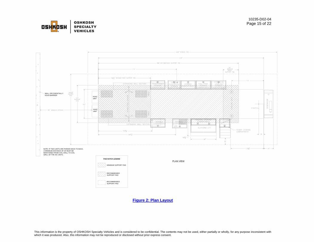
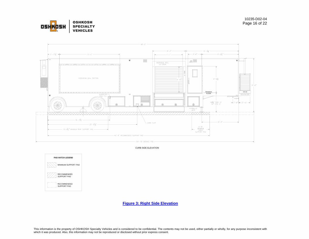
Recommended Support Pad Requirements The measurements for the recommended support pad are as follows, 10’-11” x 40’-8”. The cross hatching as shown on Figure 2: Plan Layout and Figure 3: Right Side Elevation represents the recommended support pad.
Minimum Support Pad Requirements The measurements for the minimum support pad are as follows, 10’-11” x 15’-2-1/2” for the rear pad and 10’-11” x 4’-6” for the front pad . The double cross hatching as shown on Figure 2: Plan Layout and Figure 3: Right Side Elevation represents the minimum support pad.
Support Pad Depth Recommendations for the width and length of the pad are given above. Based upon the existing site conditions, the depth should be determined by a local contractor.
Support Pad Levelness In order to ensure proper operation of the PET/CT system, the support pad(s) must be level and the deviation must not exceed .125” in 10’-0.
Recommended Service Pad The measurements for the recommended service pad are as follows, 20’-6-7/8” x 54’-10”. This will allow full service access to the mobile unit. The recommended service pad is shown on Figure 2: Plan Layout and Figure 3: Right Side Elevation.
Electro Magnetic Interference The ambient static magnetic field within the region of the gantry should not exceed 1 Gauss (10-4 Tesla) peak at the detector.
Vehicle Access A firm, level surface is required around the mobile unit in order to provide access to the site, patient access to the mobile unit, and servicing of the mobile unit.
This information is the property of OSHKOSH Specialty Vehicles and is considered to be confidential. The contents may not be used, either partially or wholly, for any purpose inconsistent with which it was produced. Also, this information may not be reproduced or disclosed without prior express consent.

10235-D02-04 Page 8 of 22
Recommended Attachment to the Facility An inflatable air bag or soft seal is recommended at the point of connection from the unit to the facility. Fixed or solid connections may hinder imaging quality. Contact Oshkosh Specialty Vehicles or the local Siemens representative prior to construction if the proposed connection varies from the recommended.
Swing Clearance Note Please verify the actual dimensions of the rearmost projections on the cab of your tractor to the centerline of tandem suspension or centerline of the fifth wheel plate on your tractor. Refer to Figure 9: Turning Requirements for proper tractor sizing information.
Air Conditioning Air Flow Clearance The following clearances for acceptable air conditioning condenser air flow have been established between wall-mounted equipment and opposing units or surfaces for maximum capacity, lowest operating cost, satisfactory operation of ventilation packages, and longest service life
• Unit discharging against opposing (facing) unit – 20 feet from coil grill to coil grill
• Unit discharging against a wall or essentially solid barrier – 15 feet from coil grill to wall. See Figure 2: Plan Layout.
This information is property of OSHKOSH Specialty Vehicles and is considered to be confidential. The contents may not be used, either partially or wholly, for any purpose inconsistent with which it was produced. This information also and may not be reproduced or disclosed without prior express consent.

10235-D02-04 Page 9 of 22
Radiation Shielding Requirements
Radiation Shielding
Radiation exposure limits must be in accordance with all local, state, and federal requirements. It is the responsibility of the customer to perform a proper radiation survey in order to determine the exclusion zone.
Care should be taken when determining a site location. Factors such as shielding design, proximity to buildings, and occupancy of the surrounding areas must be considered. An exclusion zone around the mobile unit may be necessary. Refer to Figure 5: Radiation Shielding Plan View for additional information.
Radiation Field Information It is the responsibility of the customer to ensure a safe environment with respect to the radiation field. Due to radioactivity levels associated with pet patient handling and diagnostic procedures used in PET/CT scanning, an exclusion zone must be maintained while in use.
Customer must contact their local Radiation Safety Operation Official for the federal, state, and local guidelines and must comply with these safety requirements.
Operator needs to make their own exposure dose measurements to include radiation from patients when determining the outside “Keep Away Zone” (chained-off area).
This information is the property of OSHKOSH Specialty Vehicles and is considered to be confidential. The contents may not be used, either partially or wholly, for any purpose inconsistent with which it was produced. Also, this information may not be reproduced or disclosed without prior express consent.

10235-D02-04 Page 10 of 22
Customer Power Requirements
It is the operator’s responsibility to verify that the shore power receptacle is of the same type and voltage as the connection that is supplied by Oshkosh Specialty Vehicles. Failure to do this can result in injury or death to the operator of the mobile unit as well as irreparable damage to the mobile unit.
The standard connector for the unit is a Russellstoll DS2504MP000/DF2032, 480V 200A Plug. If an existing site currently implements a different connector or connector configuration, please contact Oshkosh Specialty Vehicles in order to arrange for a compatible power connector before the unit leaves the facility.
Lockout/Tagout A Lockout/Tagout provision in accordance with OSHA Standard 1910.147 is required. The facility shore power disconnect device must be located within 40’- 0” of the unit and must provide for an effective lockout/tagout to facilitate safe service and maintenance of the unit.
Electrical Service A single electrical power source is required for operation of the PET/CT system. 3/N/PE AC 480V service fused at 150 amperes.
Configuration Three phase, five wire, wye connection, with neutral and ground. (5 wire 3/N/PE AC 480V)
Load Regulation at Line Frequency Wires are to be sized such that the line voltage drops from the power source to the mobile unit is less then 2.5% of the nominal voltage for the rated load of the mobile unit.
Frequency 60Hz ±2.0Hz.
Phase Balance The phase balance is 3% maximum of lowest phase-to-phase voltage.
Maximum Voltage Variation The maximum voltage variation is +11% / -4% from a nominal steady state (under the worst case conditions of line voltage).
Connector Type The mobile unit is supplied with a 35’-0” useable power cable and male conductor. Unless otherwise specified, the connector type is a Russellstoll DS2504MP000/DF2032, 480V 200A rated plug.
This information is property of OSHKOSH Specialty Vehicles and is considered to be confidential. The contents may not be used, either partially or wholly, for any purpose inconsistent with which it was produced. This information also and may not be reproduced or disclosed without prior express consent.
10235-D02-04 Page 11 of 22
Customer Facility The customer facility must have the matching receptacle as specified in Figure 7: Russellstoll Receptacle, Service Disconnect and Figure 8: Russellstoll Receptacle Chart. Unless otherwise specified, the receptacle type to be used must be a Russellstoll DF2504FRAB0 female connector.
Input Power • Frequency: 60Hz ±2.0Hz
• Regulation: Load regulation must not exceed 2.5%.
• Phase Imbalance: The difference between the highest line-to-line voltage and lowest line-to-line voltage must not exceed 3% of the lowest line-to-line voltage.
Power Source Monitoring (Facility Only) NOTE: Perform a power audit first.
A power analyzer should be used to check the proposed Mobile Siemens PET/CT Series facility site power for average line voltage, surges, sags, reclosures, impulses, frequency and microcuts. A period that includes two weekends should be used to simulate several days of normal use. Analysis of the data and site history of any previous power problems with other X-ray systems or computer installations should be reviewed with your power and ground representative. Verify “brown-out” (low voltage) conditions, which may occur during summer months, will not exceed the allowable range.
Some analyzer models that are suitable for power monitoring are:
• Dranetz Model 658
• Dranetz Model 656A
• BMI 3630
• RPM
This information is property of OSHKOSH Specialty Vehicles and is considered to be confidential. The contents may not be used, either partially or wholly, for any purpose inconsistent with which it was produced. This information also and may not be reproduced or disclosed without prior express consent.
10235-D02-04 Page 12 of 22
Mobile Grounding Requirements
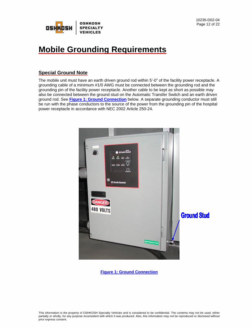
Special Ground Note The mobile unit must have an earth driven ground rod within 5’-0” of the facility power receptacle. A grounding cable of a minimum #1/0 AWG must be connected between the grounding rod and the grounding pin of the facility power receptacle. Another cable to be kept as short as possible may also be connected between the ground stud on the Automatic Transfer Switch and an earth driven ground rod. See Figure 1: Ground Connection below. A separate grounding conductor must still be run with the phase conductors to the source of the power from the grounding pin of the hospital power receptacle in accordance with NEC 2002 Article 250-24.
Figure 1: Ground Connection
This information is the property of OSHKOSH Specialty Vehicles and is considered to be confidential. The contents may not be used, either partially or wholly, for any purpose inconsistent with which it was produced. Also, this information may not be reproduced or disclosed without prior express consent.

10235-D02-04 Page 13 of 22
Telephone and Data Service Requirements
Telephone Service The mobile unit is supplied with three (3) telephone connections. The connector type that is used is a Hubbell model PH-6595 (inlet) with a model PH-6624 connector body.
The customer is required to purchase and install three (3) Hubbell all weather telephone connections, model PH-6597 for use at the site.
Three Hubbell model PH-6599 telephone-connecting cables are included with the mobile unit. The cables measure 50’-0” in length.
Data Service The mobile unit is supplied with two (2) data line connections that utilize RJ-45 outlets.
The customer is required to purchase the data connection cables for use with the data line connections. The data line connections require a 50’-0” CAT-5E cable with RJ-45 connections.
This information is property of OSHKOSH Specialty Vehicles and is considered to be confidential. The contents may not be used, either partially or wholly, for any purpose inconsistent with which it was produced. This information also and may not be reproduced or disclosed without prior express consent.
10235-D02-04 Page 14 of 22
This information is the property of OSHKOSH Specialty Vehicles and is considered to be confidential. The contents may not be used, either partially or wholly, for any purpose inconsistent with which it was produced. Also, this information may not be reproduced or disclosed without prior express consent.
Portable Sink (optional)
Water Supply Tank
Water Requirements
An optional portable self-contained sink is available. Within the portable sink assembly is the water supply and wastewater tank.
The drain for the water supply tank is located below the underbody compartment door. The drain valve is located in the underbody compartment.
The water supply tank can be filled from within the compartment by using the supplied adapter, or from the exterior of the mobile unit by using the connection on the underbody compartment door and the supplied hose.
A 35-gallon water supply tank is located on the left side of the mobile unit in the underbody compartments, which supplies the HVAC system.
During winter conditions, provisions must be made to ensure that water lines do not freeze because of weather conditions.
10235-D02-04 Page 15 of 22
PLAN VIEW
WALL OR ESSENTIALLYSOLID BARRIER
NOTE: IF TWO UNITS ARE PARKED BACK TO BACK,A MINIMUM DISTANCE OF 20' MUST BEMAINTAINED FROM COIL GRILL TO COILGRILL OF THE A/C UNITS.
HVACUNIT
HVACUNIT
PAD HATCH LEGEND
MINIMUM SUPPORT PAD
RECOMMENDED SUPPORT PAD
RECOMMENDED SUPPORT PAD
Figure 2: Plan Layout
This information is the property of OSHKOSH Specialty Vehicles and is considered to be confidential. The contents may not be used, either partially or wholly, for any purpose inconsistent with which it was produced. Also, this information may not be reproduced or disclosed without prior express consent.
10235-D02-04 Page 16 of 22
PAD HATCH LEGEND
MINIMUM SUPPORT PAD
RECOMMENDED SUPPORT PAD
RECOMMENDED SUPPORT PAD
CURB SIDE ELEVATION
FINISHED FLOOR
X-RAY ON
Figure 3: Right Side Elevation
This information is the property of OSHKOSH Specialty Vehicles and is considered to be confidential. The contents may not be used, either partially or wholly, for any purpose inconsistent with which it was produced. Also, this information may not be reproduced or disclosed without prior express consent.

10235-D02-04 Page 17 of 22
ABS
ESCAPE HATCH
LEFTSIDE ELEVATION VIEW
PAD HATCH LEGEND
MINIMUM SUPPORT PAD
RECOMMENDED SUPPORT PAD
RECOMMENDED SUPPORT PAD
AMBER
RED
RED
RED
RED
Figure 4: Left Side Elevation
This information is the property of OSHKOSH Specialty Vehicles and is considered to be confidential. The contents may not be used, either partially or wholly, for any purpose inconsistent with which it was produced. Also, this information may not be reproduced or disclosed without prior express consent.

10235-D02-04 Page 18 of 22
Figure 5: Radiation Shielding Plan View
This information is the property of OSHKOSH Specialty Vehicles and is considered to be confidential. The contents may not be used, either partially or wholly, for any purpose inconsistent with which it was produced. Also, this information may not be reproduced or disclosed without prior express consent.

10235-D02-04 Page 19 of 22
PAD HATCH LEGEND
MINIMUM SUPPORT PAD
RECOMMENDED SUPPORT PAD
RECOMMENDED SUPPORT PAD
5818" RIDE HT.
52 3/8" SITE HT.581
8" RIDE HT.52 3/8" SITE HT.
Figure 6: Stair / Lift / Wall Elevation
This information is the property of OSHKOSH Specialty Vehicles and is considered to be confidential. The contents may not be used, either partially or wholly, for any purpose inconsistent with which it was produced. Also, this information may not be reproduced or disclosed without prior express consent.

10235-D02-04 Page 20 of 22
Figure 7: Russellstoll Receptacle, Service Disconnect
This information is the property of OSHKOSH Specialty Vehicles and is considered to be confidential. The contents may not be used, either partially or wholly, for any purpose inconsistent with which it was produced. Also, this information may not be reproduced or disclosed without prior express consent.

10235-D02-04 Page 21 of 22
Figure 8: Russellstoll Receptacle Chart
This information is the property of OSHKOSH Specialty Vehicles and is considered to be confidential. The contents may not be used, either partially or wholly, for any purpose inconsistent with which it was produced. Also, this information may not be reproduced or disclosed without prior express consent.

10235-D02-04 Page 22 of 22
Figure 9: Turning Requirements
This information is the property of OSHKOSH Specialty Vehicles and is considered to be confidential. The contents may not be used, either partially or wholly, for any purpose inconsistent with which it was produced. Also, this information may not be reproduced or disclosed without prior express consent.


![Introducing Time of Flight and Resolution Recovery Image ...rahmim/research_work/... · as the Siemens Biograph mCT, to acquire TOF information for each coincidence event [15,17].](https://static.fdocuments.in/doc/165x107/601c172f3ea03678464f171c/introducing-time-of-flight-and-resolution-recovery-image-rahmimresearchwork.jpg)
