![Sutton Elbert Griggs--Light on Racial Issues ([c1921])](https://static.fdocuments.in/doc/165x107/577d23981a28ab4e1e9a3ca8/sutton-elbert-griggs-light-on-racial-issues-c1921.jpg)
SITE GUIDE - Griggs Timber Company
2
www.itwcp-offsite.co.uk SITE GUIDE ALPINE Download the Cullen App. See inside for details. INSTALLATION • After studying the joist designer’s layout drawing, decide which area of the floor is to be erected first and from which end of the building • Place the required joists referring to SpaceJoist layout drawing next to the correct area of the building • Check to see if the joists require internal support and/or have differing end details. If any of these conditions exist, attention should be paid as to the correct orientation of the joist before hoisting onto the scaffold • Care should be taken not to damage the metal webs when hoisting onto the scaffold i.e. hoisting straps should be placed around timber chords and not around the metal webs • The first joist is normally positioned a dimension of 50mm from the inside face of the brickwork measured to the edge of the joist (see figure 1&2) • The remaining joists are positioned at the centres specified on the layout drawing (e.g. 600, 480 or 400mm) but set out from the inside face of the brickwork, thus making the distance from the 1st joist to the 2nd equal to the specified joist centres minus 50mm • Joists may be required to support stair trimmers and partition walls which, in most cases, will be in addition to the joists occurring at the specified centres • As an aid to setting the joists in their correct positions it is advisable to use a length of tiling batten positioned close to the external support brickwork and temporarily nailed to each joist (see figure 1&2) Once the joists have been positioned the strongback bridging, partition noggins (if required) and restraint straps can be installed • If the joists are supported at 3 positions it is important to check that they are in contact with the supports at all locations. To achieve this it may be necessary to place packing (slate or similar) between the top of the brickwork and the underside of the joist • Care should be taken to ensure that adjacent joists are level with each other and that joists are level along their length Figure 2 Tiling batten Section 50 600 550 Figure 1 Tiling batten DO’S AND DONT’S Do’s Dont's Install the joists as they have been designed: refer to the joist designer's drawings for the correct orientation, spacing etc. Lift the joists in a vertical position Do not walk on or store building material on unbraced joists. Do not drill holes through any part of the joist Do not cut through or remove the webs Do not cut through the chords Do not cut notches in any part of the joist 923552 / 3961 / 07 .17 TEMPORARY SAFETY BRACING FOR FLOORS The builder is responsible for identifying and minimising the risks involved in erecting SpaceJoists to ensure the health and safety of all workers is maintained. Builders should be aware of the health and safety responsibilities imposed on them by the Construction (Design and Management) Regulations 2015. Proper erection procedures and bracing are vital to the safe construction of SpaceJoist floors. The following notes may assist builders in preparing a safety assessment: • Unbraced floors may be unstable • DO NOT walk on unbraced joists • DO NOT store building materials on unbraced floors • SpaceJoists should be erected straight and vertical. Horizontal deviation no more than 10mm. Vertical deviation no more than 2mm • Temporary bracing consists of diagonal brace, longitudinal brace and permanent Strongback Bridging • All longitudinal braces, diagonal braces and Strongbacks should be completely installed and fully nailed • Lateral strength should be provided by a diagonally braced system across a minimum of 3 joists as shown below • Construction material may only be stored on joists when all bracing is in place. Material should be spread over at least 4 joists and not more than 1.5m from a support • Decking / plasterboard may be stacked no higher than 250mm (150kg / joist @ 600mm centres, 100kg / joist @ 400mm centres) on fully braced floors • Flooring should be fully fixed to the joists before additional loads are placed on the floor • Temporary bracing can be progressively removed as decking is fixed Construction materials shall only be stored in the 1.5m edge zone at one end of the joist only. Max height 250mm. Do not store construction material close to trimmers. Tiling batten. 2.4m max 2.4m max Strongback bracing fixed as details below. 22 X 97mm diagonal brace. Nail all binders and braces to each joist with No.2 (3.35 X 65mm) nails. Min. 675mm cured masonry above hanger level or as advised by hanger manufacturer. 22 X 97mm longitudinal binders connected to diagonal bracing at one end of the joist run. 1.5m max SITE STORAGE Site storage is intended to be temporary prior to erection. • The fabrication and delivery of joists should, therefore, be arranged to minimise the storage time both at the manufacturer’s premises and on site • ITW Construction Products recommend that the joists are delivered wrapped in protective plastic covering which will protect the joists from short term exposure to inclement weather • The joists should be stored horizontally, such that they are approximately 75mm clear of the ground and vegetation • Joists should be supported in such a way as to prevent the likelihood of distortion DOWNLOAD CULLEN APP DECKING Attention should always be paid to the particular manufacturer’s instructions but, listed below are some good practice guidelines when installing floor decking. • Tongue and groove boards should be laid with their long edges running perpendicular to the joists, with the joint between the short edges occurring on the centreline of a joist. • Square edged boards need to be supported continuously along all edges. • Nail fixings - 3mm ring shank nails with a minimum length equal to 2.5 x board thickness. • Screw fixings - minimum No. 8 (4.2mm) particle board screws with a minimum length equal to 2.5 x board thickness. Nails or screws should be positioned 9mm from the board edge and at 200mm centres along all support and edges (see below) • Chipboard is similar to other timber products in that it will expand when exposed to moisture and high humidity. Consequently, allowances must be made to accommodate potential expansion. It is recommended to leave a perimeter gap of 10 - 12mm between the edge of the board and the face of the brickwork. It is also recommended to leave a gap of 2mm between edges of abutting boards. 200mm centres Place hoisting straps around timber chords
Transcript of SITE GUIDE - Griggs Timber Company
www.itwcp-offsite.co.uk
SITE GUIDE
ALPINE
Download the Cullen App. See inside for details.
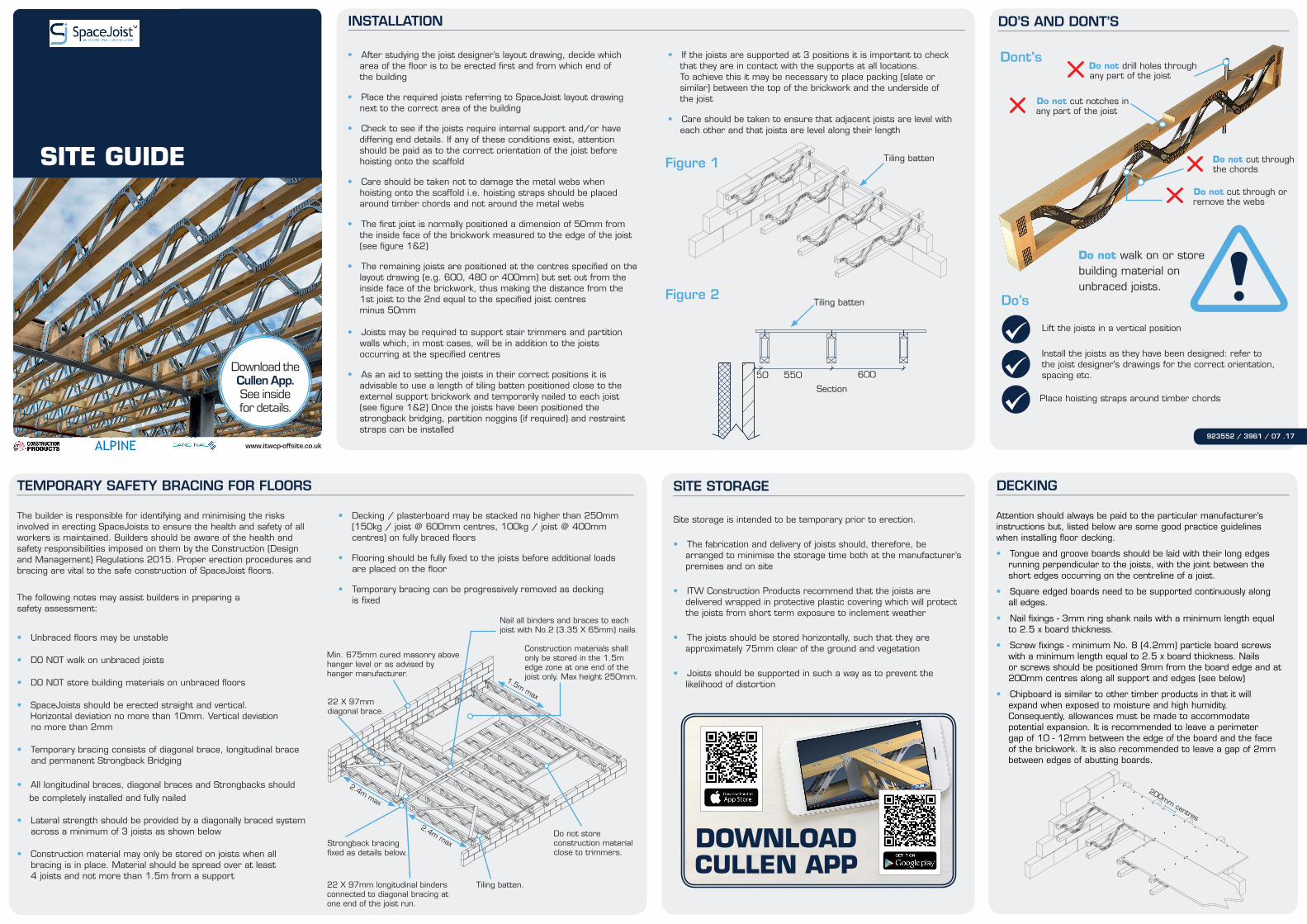
INSTALLATION
• After studying the joist designer’s layout drawing, decide which area of the floor is to be erected first and from which end of the building
• Place the required joists referring to SpaceJoist layout drawing next to the correct area of the building
• Check to see if the joists require internal support and/or have differing end details. If any of these conditions exist, attention should be paid as to the correct orientation of the joist before hoisting onto the scaffold
• Care should be taken not to damage the metal webs when hoisting onto the scaffold i.e. hoisting straps should be placed around timber chords and not around the metal webs
• The first joist is normally positioned a dimension of 50mm from the inside face of the brickwork measured to the edge of the joist (see figure 1&2)
• The remaining joists are positioned at the centres specified on the layout drawing (e.g. 600, 480 or 400mm) but set out from the inside face of the brickwork, thus making the distance from the 1st joist to the 2nd equal to the specified joist centres minus 50mm • Joists may be required to support stair trimmers and partition walls which, in most cases, will be in addition to the joists occurring at the specified centres
• As an aid to setting the joists in their correct positions it is advisable to use a length of tiling batten positioned close to the external support brickwork and temporarily nailed to each joist (see figure 1&2) Once the joists have been positioned the strongback bridging, partition noggins (if required) and restraint straps can be installed
• If the joists are supported at 3 positions it is important to check that they are in contact with the supports at all locations. To achieve this it may be necessary to place packing (slate or similar) between the top of the brickwork and the underside of the joist
• Care should be taken to ensure that adjacent joists are level with each other and that joists are level along their length
Figure 2Tiling batten
Section
50 600550
Figure 1 Tiling batten
DO’S AND DONT’S
Do’s
Dont's
Install the joists as they have been designed: refer to the joist designer's drawings for the correct orientation, spacing etc.
Lift the joists in a vertical position
Do not walk on or store building material on unbraced joists.
Do not drill holes through any part of the joist
Do not cut through or remove the webs
Do not cut through the chords
Do not cut notches in any part of the joist
923552 / 3961 / 07 .17
TEMPORARY SAFETY BRACING FOR FLOORS
The builder is responsible for identifying and minimising the risks involved in erecting SpaceJoists to ensure the health and safety of all workers is maintained. Builders should be aware of the health and safety responsibilities imposed on them by the Construction (Design and Management) Regulations 2015. Proper erection procedures and bracing are vital to the safe construction of SpaceJoist floors.
The following notes may assist builders in preparing a safety assessment:
• Unbraced floors may be unstable
• DO NOT walk on unbraced joists
• DO NOT store building materials on unbraced floors
• SpaceJoists should be erected straight and vertical. Horizontal deviation no more than 10mm. Vertical deviation no more than 2mm
• Temporary bracing consists of diagonal brace, longitudinal brace and permanent Strongback Bridging • All longitudinal braces, diagonal braces and Strongbacks should be completely installed and fully nailed
• Lateral strength should be provided by a diagonally braced system across a minimum of 3 joists as shown below
• Construction material may only be stored on joists when all bracing is in place. Material should be spread over at least 4 joists and not more than 1.5m from a support
• Decking / plasterboard may be stacked no higher than 250mm (150kg / joist @ 600mm centres, 100kg / joist @ 400mm centres) on fully braced floors
• Flooring should be fully fixed to the joists before additional loads are placed on the floor
• Temporary bracing can be progressively removed as decking is fixed
Construction materials shall only be stored in the 1.5m edge zone at one end of the joist only. Max height 250mm.
Do not store construction material close to trimmers.
Tiling batten.
2.4m max
2.4m maxStrongback bracing fixed as details below.
22 X 97mm diagonal brace.
Nail all binders and braces to each joist with No.2 (3.35 X 65mm) nails.
Min. 675mm cured masonry above hanger level or as advised by hanger manufacturer.
22 X 97mm longitudinal binders connected to diagonal bracing at one end of the joist run.
1.5m max
SITE STORAGE
Site storage is intended to be temporary prior to erection.
• The fabrication and delivery of joists should, therefore, be arranged to minimise the storage time both at the manufacturer’s premises and on site
• ITW Construction Products recommend that the joists are delivered wrapped in protective plastic covering which will protect the joists from short term exposure to inclement weather
• The joists should be stored horizontally, such that they are approximately 75mm clear of the ground and vegetation
• Joists should be supported in such a way as to prevent the likelihood of distortion
DOWNLOAD CULLEN APP
DECKING
Attention should always be paid to the particular manufacturer’s instructions but, listed below are some good practice guidelines when installing floor decking.
• Tongue and groove boards should be laid with their long edges running perpendicular to the joists, with the joint between the short edges occurring on the centreline of a joist.
• Square edged boards need to be supported continuously along all edges.
• Nail fixings - 3mm ring shank nails with a minimum length equal to 2.5 x board thickness.
• Screw fixings - minimum No. 8 (4.2mm) particle board screws with a minimum length equal to 2.5 x board thickness. Nails or screws should be positioned 9mm from the board edge and at 200mm centres along all support and edges (see below)
• Chipboard is similar to other timber products in that it will expand when exposed to moisture and high humidity. Consequently, allowances must be made to accommodate potential expansion. It is recommended to leave a perimeter gap of 10 - 12mm between the edge of the board and the face of the brickwork. It is also recommended to leave a gap of 2mm between edges of abutting boards.
200mm centres
Place hoisting straps around timber chords
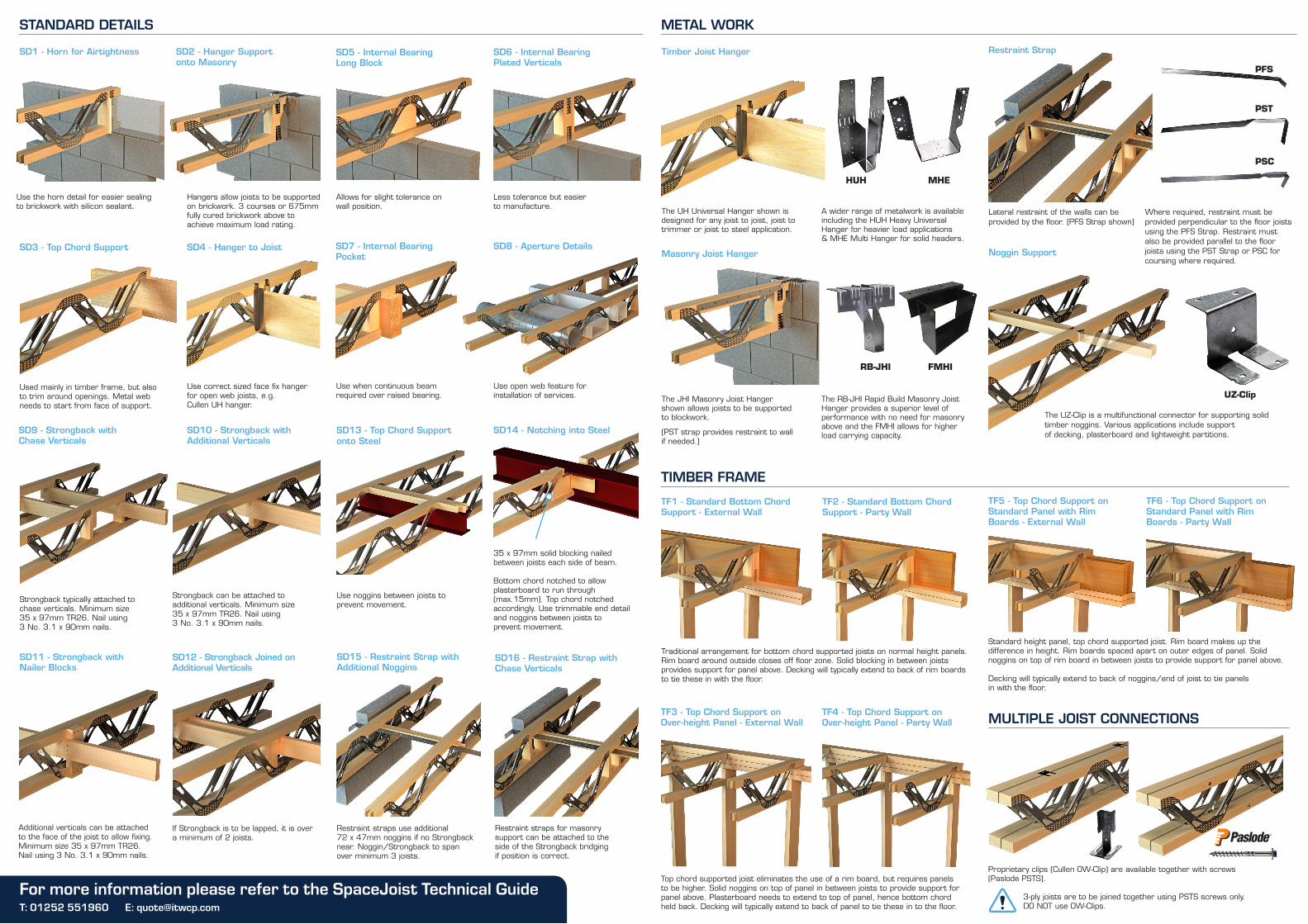
STANDARD DETAILS METAL WORK
TIMBER FRAME
MULTIPLE JOIST CONNECTIONS
TF2 - Standard Bottom Chord Support - Party Wall
Traditional arrangement for bottom chord supported joists on normal height panels. Rim board around outside closes off floor zone. Solid blocking in between joists provides support for panel above. Decking will typically extend to back of rim boards to tie these in with the floor.
TF3 - Top Chord Support on Over-height Panel - External Wall
TF4 - Top Chord Support on Over-height Panel - Party Wall
Top chord supported joist eliminates the use of a rim board, but requires panels to be higher. Solid noggins on top of panel in between joists to provide support for panel above. Plasterboard needs to extend to top of panel, hence bottom chord held back. Decking will typically extend to back of panel to tie these in to the floor.
TF1 - Standard Bottom Chord Support - External Wall
TF5 - Top Chord Support on Standard Panel with Rim Boards - External Wall
TF6 - Top Chord Support on Standard Panel with Rim Boards - Party Wall
Standard height panel, top chord supported joist. Rim board makes up the difference in height. Rim boards spaced apart on outer edges of panel. Solid noggins on top of rim board in between joists to provide support for panel above.
Decking will typically extend to back of noggins/end of joist to tie panels in with the floor.
The UH Universal Hanger shown is designed for any joist to joist, joist to trimmer or joist to steel application.
A wider range of metalwork is available including the HUH Heavy Universal Hanger for heavier load applications & MHE Multi Hanger for solid headers.
The JHI Masonry Joist Hanger shown allows joists to be supported to blockwork.
(PST strap provides restraint to wall if needed.)
The RB-JHI Rapid Build Masonry Joist Hanger provides a superior level of performance with no need for masonry above and the FMHI allows for higher load carrying capacity.
HUH
RB-JHI FMHI
MHE
Timber Joist Hanger
Masonry Joist Hanger
PST
Lateral restraint of the walls can be provided by the floor. (PFS Strap shown)
Where required, restraint must be provided perpendicular to the floor joists using the PFS Strap. Restraint must also be provided parallel to the floor joists using the PST Strap or PSC for coursing where required.
Restraint Strap
PSC
The UZ-Clip is a multifunctional connector for supporting solid timber noggins. Various applications include support of decking, plasterboard and lightweight partitions.
Noggin Support
UZ-Clip
PFS
SD1 - Horn for Airtightness SD2 - Hanger Support onto Masonry
Use the horn detail for easier sealing to brickwork with silicon sealant.
Hangers allow joists to be supported on brickwork. 3 courses or 675mm fully cured brickwork above to achieve maximum load rating.
SD3 - Top Chord Support
Used mainly in timber frame, but also to trim around openings. Metal web needs to start from face of support.
Use correct sized face fix hanger for open web joists, e.g. Cullen UH hanger.
SD4 - Hanger to Joist
Use when continuous beam required over raised bearing.
Use open web feature for installation of services.
SD5 - Internal Bearing Long Block
Allows for slight tolerance on wall position.
SD6 - Internal Bearing Plated Verticals
Less tolerance but easier to manufacture.
SD7 - Internal Bearing Pocket
SD8 - Aperture Details
Additional verticals can be attached to the face of the joist to allow fixing. Minimum size 35 x 97mm TR26. Nail using 3 No. 3.1 x 90mm nails.
If Strongback is to be lapped, it is over a minimum of 2 joists.
SD9 - Strongback with Chase Verticals
SD10 - Strongback with Additional Verticals
SD11 - Strongback with Nailer Blocks
SD12 - Strongback Joined on Additional Verticals
Strongback typically attached to chase verticals. Minimum size 35 x 97mm TR26. Nail using 3 No. 3.1 x 90mm nails.
Strongback can be attached to additional verticals. Minimum size 35 x 97mm TR26. Nail using 3 No. 3.1 x 90mm nails.
SD15 - Restraint Strap with Additional Noggins
SD16 - Restraint Strap with Chase Verticals
Restraint straps for masonry support can be attached to the side of the Strongback bridging if position is correct.
Restraint straps use additional 72 x 47mm noggins if no Strongback near. Noggin/Strongback to span over minimum 3 joists.
SD13 - Top Chord Support onto Steel
Use noggins between joists to prevent movement.
SD14 - Notching into Steel
Bottom chord notched to allow plasterboard to run through (max.15mm). Top chord notched accordingly. Use trimmable end detail and noggins between joists to prevent movement.
35 x 97mm solid blocking nailed between joists each side of beam.
For more information please refer to the SpaceJoist Technical GuideProprietary clips (Cullen OW-Clip) are available together with screws (Paslode PSTS).
3-ply joists are to be joined together using PSTS screws only. DO NOT use OW-Clips.T: 01252 551960 E: [email protected]