Site Conditions Superstructure
11
technical report city building 8 1 Site Conditions The site falls 1,2m in a Northerly direction over its 55 m length. of the site . A new storm water and sewer connection will be required on Paul Kruger Street at the North-Westerly corner of the site, which is the lowest point of Natural Ground Level. A water and electricity connection will be required at the opposite South Eastern corner of the site on Schoeman Street. The soil and ground water conditions are unknown, and tests are currently impossible as the site is built up. Very few building plans are available from the City Council for buildings on the site itself. Normal soil conditions were reasonably assumed, through a study of neighbouring building plans that were available from the City Council. The FinPark and Van Erkom building sections show concrete footings. The Lewis building (on the site) on c/o Schoeman and Paul Kruger Street on the site has an existing basement level, but detail on the type of basement could not be acquired. It was thus assumed that no trouble soil is present, and that basement construction is viable. A reinforced concrete post and beam structure was chosen as the most suitable for the Super-structure of the building. The speed of steel construction and the smaller workforce required compared to concrete frame construction makes structural steel an attractive option, but with a building height of 18 m, as in this case, fire regulations prohibit the use of unprotected structural steel: Special treatment of structural members, e.g. cladding the steel in concrete (!) or vermiculite is required for structures higher than 15m (SABS, 1990:170). This increases the price margin between steel and concrete (with steel construction already approximately 10 to 15% more expensive) and makes steel financially unfeasible. The South African Building Industry is geared towards concrete frame construction, and a tradition of concrete construction exists. A concrete structure has the added advantage of providing building mass that acts as a solar heat store, providing an ideal thermal lag effect. Despite the intensive use of shuttering associated with concrete, steel shuttering can be re-used for other projects. Reinforced concrete further more has lower embodied energy than steel. This is based on information from Bjorn Berge’s Ecology of Building Materials. 100% recycled steel receives a Primary Energy Consumption Value of 10, compared structural concrete that receives a value of 1. (BERGE, 2003: 20) Albeit measured by European standards, this was assumed to be relatable to the South African context. Basement parking, the existing city grid and the set baseline requirement of street edge definition for Paul Kruger and Schoeman Streets determined a rational grid. Superstructure Fig 8-1 Column grid: Base grid and addtions University of Pretoria etd – Pienaar, R (2005)
Transcript of Site Conditions Superstructure

technical report
city building 8 1
Site Conditions
The site falls 1,2m in a Northerly direction over its 55 m length. of the site . A new storm water and sewer connection will be required on Paul Kruger Street at the North-Westerly corner of the site, which is the lowest point of Natural Ground Level. A water and electricity connection will be required at the opposite South Eastern corner of the site on Schoeman Street.
The soil and ground water conditions are unknown, and tests are currently impossible as the site is built up. Very few building plans are available from the City Council for buildings on the site itself. Normal soil conditions were reasonably assumed, through a study of neighbouring building plans that were available from the City Council. The FinPark and Van Erkom building sections show concrete footings. The Lewis building (on the site) on c/o Schoeman and Paul Kruger Street on the site has an existing basement level, but detail on the type of basement could not be acquired. It was thus assumed that no trouble soil is present, and that basement construction is viable.
A reinforced concrete post and beam structure was chosen as the most suitable for the Super-structure of the building. The speed of steel construction and the smaller workforce required compared to concrete frame construction makes structural steel an attractive option, but with a building height of 18 m, as in this case, fire regulations prohibit the use of unprotected structural steel: Special treatment of structural members, e.g. cladding the steel in concrete (!) or vermiculite is required for structures higher than 15m (SABS, 1990:170). This increases the price margin between steel and concrete (with steel construction already approximately 10 to 15% more expensive) and makes steel financially unfeasible.
The South African Building Industry is geared towards concrete frame construction, and a tradition of concrete construction exists. A concrete structure has the added advantage of providing building mass that acts as a solar heat store, providing an ideal thermal lag effect. Despite the intensive use of shuttering associated with concrete, steel shuttering can be re-used for other projects.
Reinforced concrete further more has lower embodied energy than steel. This is based on information from Bjorn Berge’s Ecology of Building Materials. 100% recycled steel receives a Primary Energy Consumption Value of 10, compared structural concrete that receives a value of 1. (BERGE, 2003: 20) Albeit measured by European standards, this was assumed to be relatable to the South African context.
Basement parking, the existing city grid and the set baseline requirement of street edge definition for Paul Kruger and Schoeman Streets determined a rational grid.
Superstructure
Fig 8-1 Column grid: Base grid and addtions
UUnniivveerrssiittyy ooff PPrreettoorriiaa eettdd –– PPiieennaaaarr,, RR ((22000055))

tech
nica
l rep
ort
city building 8 2
technical report
city building 8 3
330x440 reinforced concrete columns set at 7,9m x 5,33 m centres form the base grid. The column size remains consistent through basement, ground and first floor levels, after which 220x330 suffice for the top 3 residential floors.Spatial needs and architectural elements such as the double volume atrium, level changes and tree planters create secondary grid lines.
To account for thermal contraction and expansion the building is separated from neighbouring FinPark Building with a 50mm movement joint filled with polystyrene sheets. A 20 mm movement joint is incorporated within the building on grid line 5.
A 200 mm steel reinforced concrete slab spans 5m between 200mm downstand beams. The beams span 7,8m between columns on the North-South axis. Lateral stability is ensured by 200m downstand beams in the short 5,33m East-West axis. Where used, these lateral stability beams are incorporated only on South facing facades to maximize Northern light entry into rooms, with windows taken to ceiling height. Slab cantilevers are limited to 2m, strengthened through 200mm downstand beams.
The basement will extend up to the building line on the Southern and Western edges. Because excavation can not take place over the building line and to keep the pavement untouched and usable for the period of construction, piles will be required to stabilize the soil, after which excavation of the basement can take place. The outer wall of the basement works with a Drained system: a cavity wall ensures that damp stays well out of the basement. Water is pumped to the stormwater connection. The cavity was made 200mm wide, to allow sewer and rainwater pipes from the building above to turn in the space. The design of the foundations and retaining wall be administered by a structural engineer according to SABS 0161 after soil tests have been completed.
The Basement
Fig
8-2
Rein
forc
ed c
oncr
ete
Post
and
Bea
m S
truct
ure
Fig 8-3 Structural Calculation for column size - See Appendix D for complete calculations
Fig 8-4 Section through basement edge - Informed by Drained system detail in (WEGELIN, 2000: 26)
UUnniivveerrssiittyy ooff PPrreettoorriiaa eettdd –– PPiieennaaaarr,, RR ((22000055))

tech
nica
l rep
ort
city building 8 2
technical report
city building 8 3
Material Palette
Red brick masonry work Pretoria has a redbrick aesthetic, and in the CBD numerous red brick buildings can be seen, including neighbouring Laboria building on the Southern corner of Schoeman and Paul Kruger Streets (see Fig 7-7), the Old Raadsaal and various other historic buildings on Church Square.
Red Brick masonry is a good absorber of heat. Structural brickwork has a density of 2500 kg/m3, the same as reinforced concrete, while non-structural brickwork has a density of 2000 kg/m3. (Smit, 2000) The matte finish of brick and the darker, typically ruby colour there-of increases the material’s heat absorption capacity.
Fair-face Concrete formworkFair-face Concrete is a contemporary building aesthetic. Through the use of pigments colour variations can be implemented where required. The cost of adding pigments to the concrete mix can be justified through the robustness of the product compared to plaster and paint. Steven Holl uses white and grey pigments to great effect in the Fukuoka housing scheme (see fig 7-5). Pigmented concrete will specifically be used for interior spaces. In the gallery lighter shades can be used for the wall exhibit, while darker shades can be used to demarcate zones on the floor.
Reinforced concrete formwork, with its high density of 2500kg/m3, is ideal for use on the Western façade: Solar heat is absorbed and released into the building at night. An off-shutter finish will increase absorption.
Glass or Ceramic Mosaic Tiling Talking Beads manufactures hand-made Arts and Crafts, and so the artists are available to design and implement mosaic artworks. Mosaic tiles can be used to distinguish
elements and mark important places as required. The artworks can be splashed onto the robust concrete elements in subtle or generous degrees. Colourful mosaic on brute concrete is a contempor ary South African architectural aesthetic, as can be seen in the Constitutional Court design by OMM Design Workshop and Urban Solutions (see Precedent Study), as well as in the design of bollards and seating at the recently completed DTI Campus by Studio 3 (fig 7-8).Ceramic tiles will also be used selectively on the public square, as well as for interior tiling in the residential component.
Galvanised Steel ElementsGalvanised mild steel is used to construct lighter elements that clip on to the main concrete structure. Stairways, louver systems, glazing support systems and roof elements create a consistent aesthetic, while different grains of roughness can be used to define different places, as is the case in the Department of Trade and Industry Campus in Sunnyside. (fig7-9 to 7-10) Steven Holl clips lighter steel elements to the main structure at the Fukoaka housing scheme (fig 7-6) to celebrate the element.
GlassWindows allow light to enter spaces. It can be opened to ventilate and cool. Clear glass will be shaded and used in most instances. Safety glass is used as required by building safety regulations. 8mm laminated glass without opening sections is used for acoustic purposes in the gallery. MiscellaneousTimber is used selectively in interior applications for balustrade detailing and movable panels in the gallery. Anodised aluminium sections are selectively used for window frames and ceiling systems.
UUnniivveerrssiittyy ooff PPrreettoorriiaa eettdd –– PPiieennaaaarr,, RR ((22000055))

tech
nica
l rep
ort
city building 8 4
technical report
city building 8 5
Fig 8-5 Pigmented concrete by Steven Holl - Fukuoka Housing (ASSENSIO, 2000: 295)
Fig 8-6 Steel stariway clipped to main concrete structue: Steven Holl (ASSENSIO, 2003: 296)
Fig 8-7 View to redbrick Laboria building looking west down Schoeman Street (Author, 2004)
Fig 8-8 Mosaic on bollard detail at DTI Campus Sunnyside by Studio 3
Fig 8-9 Galvanised Steel Panel for solar control on Eastern Facade at DTI Campus by Studio 3
Fig 8-10 Detail of galvanised steel louver shading system at DTI Campus,Sunnyside by Studio3
UUnniivveerrssiittyy ooff PPrreettoorriiaa eettdd –– PPiieennaaaarr,, RR ((22000055))

tech
nica
l rep
ort
city building 8 4
technical report
city building 8 5
VENTILATION AND AIR-CONDITIONING
Flats The residential units are naturally ventilated. The 8,5m deep flats have at least two outer edges with openable windows or louver systems that can be controlled by occupants to allow cross-ventilation.
Talking BeadsThe Talking Beads workshops and offices are naturally ventilated with openable window sections to the West and hot air release at roof level in the East. The Workshops and offices may be air-conditioned with split air-conditioning units if so required. A single unit can cool a total floor area of 120 sqm. The unit(s) can be accommodated on the accessible roof used as an open-air workshop by Talking Beads. This will make routine maintenance an easy process.
Gallery And Auditorium A Multi-zone, variable air volume air-conditioning system is proposed. A central chilled water plant room is located on the roof of the Western residential unit block. Cold water pipes from the Chiller Room are ducted to air-handling units. (KÖHLER, 2004) One air-handling unit is used for the gallery level (18sqm room) serving the Gallery offices and exhibition galleries, and another air-handling unit for the auditorium (8 sqm room).
The gallery air-handling-unit room has no outside wall, and a 1000x1000 shaft connects it to the roof for air outlet and intake. The auditorium air-handling unit room has an outer wall through which air can be changed. From the air-handling units air is ducted to room diffusers, for which the required ceiling space of 700mm (KÖHLER, 2004) was allowed.
RetailShops are air-conditioned with single-zone split units that serve up 120 sqm of floor space. An indoor evaporator unit is connected to outside condensing units through refrigerant piping. (KÖHLER, 2004) Condensing units are accommodated in the gallery outer wall, covered with a removable louver screen for routine maintenance See solar control section for information on screens.
Fig 8-11 Natural ventilation for flats and air-con ducts for gallery and shops
Fig 8-12 Air-conditioning layout diagram
UUnniivveerrssiittyy ooff PPrreettoorriiaa eettdd –– PPiieennaaaarr,, RR ((22000055))

tech
nica
l rep
ort
city building 8 6
technical report
city building 8 7
Kitchens And BathroomsStale air is extracted with extractor fans through 300 diameter pipes to above the residential roof level.
Basement The basement is mechanically ventilated with a supply and extract system. Air is changed at 7,5 l/s per sqm. (Köhler, 2004) No fresh air can be drawn from the entrance of the basement as is the standard procedure, as this would affect the existing ventilation system of the FinPark basement.
The multilevel square allows for air to enter the basement, specifically under the pedestrian ramp. Air also enters the basement through the central stairwell. A ventilation expert should determine whether these would supply enough fresh air to not necessitate mechanical air intake. It was assumed that mechanical air-intake will be needed, and incorporated into the design.
Fresh air is drawn from the level of the highest residential units through three 1300x1700 ducts located on the Eastern edge of the basement. (This air may still require a filter system.) Air is then extracted at the opposite (Western) basement edge at floor level through three 1500x1500 ducts, specifically to get rid of carbon monoxide, after which it is released above the street canopy level. The ducts are placed so as to prevent the occurrence of dead spots (no air movement) in the basement.
Storage space in the basement needs to have air changed at 2 to 3 l/s/sqm. Air can be extracted with fans and released into the main basement. These fans need only work when persons occupy the storage spaces.
Fig 8-13 Mechanical Basement ventilation Blue blocks = intake Cyan blocks = oultet
Fig 8-14 Stale air released above street canopy
UUnniivveerrssiittyy ooff PPrreettoorriiaa eettdd –– PPiieennaaaarr,, RR ((22000055))

tech
nica
l rep
ort
city building 8 6
technical report
city building 8 7
Solar incidence and ControlNorthern sun is controlled through roof overhangs designed to summer and winter sun angles. Eastern sun into the gallery is passively controlled through louvers and roof overhangs.
For residential units with an East-West orientation Eastern sun is considered desirable as the main source of heat in winter, and so the flats were orientated as such, with living and sleeping spaces to have maximal Eastern sun exposure.
Glazing to the West was consciously minimized. Where glazing to the West was a necessity, as is the case in some residential units, louver screens are propsed for solar control. These sunscreens on the Western facade include sliding sections, so that Western sun can be blocked entirely during summer months, while late afternoon sunshine desirable during colder winter months can be let in.
ScreensLouver screens are used extensively in the building, and are functional for security needs, as well as the screening of unsightly services. Sewer pipes, storm water pipes and air-conditioning units are kept to the outer façade, and screens are easily removable.
All louver panels are constructed as lightweight frames with louvers from cold-rolled steel plate sections that are bent, welded and drilled off-site. The entire panel is then galvanised, and bolted to a main support structure. The main support structure consists of hot-rolled galvanised steel sections, connected to the concrete or masonry structure with expansion bolts.
LightingMaximizing natural lighting is a baseline requirement and a design informant. The multi-leveled square that forms the heart of the building allows spaces around it access to natural light.
FlatsAll rooms have access to natural light. Glazing is taken to ceiling level, to maximise light into the room. Interior walls of the flats will be plastered and painted white/ light colours. Electric light will be required only to add to natural light where sufficient lux levels is not reached. (Required light levels set in Schedule of Accommodation).
Gallery The gallery has limited natural light, due in part to its Western façade and the need for acoustic control. The exhibition of artworks requires consistent lighting levels, and the lighting of the artworks will, for the most part be dependant on electrical lighting. Fig 8-15 Natural Light into the Gallery, Service Lane and Shop
UUnniivveerrssiittyy ooff PPrreettoorriiaa eettdd –– PPiieennaaaarr,, RR ((22000055))

tech
nica
l rep
ort
city building 8 8
technical report
city building 8 9
Natural light is used in addition to electric light. Different lighting qualities for individual galleries ensure distinguishable spatial qualities.
The Auditorium Foyer / Exhibition space receives light through a glazed Eastern façade. Two louvered glass boxes protrude to the West to bring filtered light into the space.
The Western Gallery receives side-lighting through the South-Western corner window box that is louvered to the West. A louvered clerestory strip window adds some louvered top lighting.The Southern Gallery receives top-lighting through reflected Northern light and Southern light, both strip windows at ceiling level. Ceilings and bulkheads that hide air-conditioning services are painted white and shaped to maximize natural light onto exhibition walls.
The Northern gallery receives light through the glazed Northern façade shaded with a 1300mm roof overhang. The central gallery offices share in light from the Northern glazed façade: A curtain with sandblasted glass up to a height of 2m ensures light without compromising privacy,. Clear glass above brings light and allows views to the outside.
An external ramp with a 1:12 fall gives disabled persons access to the raised public and cultural square and effectively the gallery. An elevator connects the basement, retail level, and Talking Beads level, and also gives quick access to the public square. Both the ramp and elevator are located centrally.
The auditorium is supplied with 2 x wheelchair spaces required according to the SABS (over 50 and under 400 seats), and two disabled parking spaces are available in the basement.
Handicapped persons access
Flats(defined as occupation class H3 in SABS 0400)34 persons on 2nd floor (calculated @ 2 persons per bedroom)54 persons on 3rd50 persons on 4thThe communal space on 2nd floor doubles as an escape route. It may have to accommodate the total of 138 persons. 1300 wide escape route provided (SABS section TT 21.2) Structural Elements/Components of a residential block in a 5 storey building require 60 minutes fire safety.
The Eastern public staircase doubles as a fire escape route, giving users access to the square. It is linked with bridges from the Northern block with one-way doors in the direction of movement for controlled access. The stair is linked to the basement with a one-way door ensuring that direct access is not possible. The 1300 mm wide staircase is partially covered with glazing and mesh as required for a staircase higher than 18m by SABS regulation TT27.1
Gallery(defined as occupation class C2 in SABS 0400)1 person per 20 sqm = 590 sqm/20 = 30 persons1300 escape route adequate
Auditorium(defined as occupation class A2 in SABS 0400)A possible 130 persons in the auditorium (incl. 120 seats and possible speaker/ performers/ personnel etc.) Escape route of 1200 provided as to SABS 0400 regulations. The steel fire stairs clip to the Western Façade of the Auditorium, and the ladder extends onto the sidewalk when needed.
Talking Beads workshops(defined as occupation A3 – educational, as the facilities
Fire Safety
UUnniivveerrssiittyy ooff PPrreettoorriiaa eettdd –– PPiieennaaaarr,, RR ((22000055))
tech
nica
l rep
ort
city building 8 8
technical report
city building 8 9
may be used for adult education. This occupation class would entail the largest possible number of people that could potentially use the building)275 sqm / 1 person per 5sqm = 55 persons1100 staiway required for persons up to 120. The 1300 mm Eastern stairway is sufficient, less than 45m from the farthest point in the workshops.
SecurityThe City Council is in the process of installing Closed Circuit Television (CCTV) systems in the Pretoria CBD to make it a safer environment for its users. Church Street already has a fully functioning CCTV system. Hopefully this will soon be the case for the entire CBD.
Passive surveillance is the prevalent security measure for the proposal. The Gallery, residences and Talking Beads are all entered from the Square, and flats and circulation spaces have views onto the square. The public spaces will be busy during the day, but at night other measures may be required:
The arcade can be closed to Paul Kruger Street, and a sliding door allows the arade to be locked to Van Erkom arcade. A security guard could easily monitor the single remaining entrance next to the market at the North Eastern corner. Alternatively a CCTV system for the building can be installed, and entrances monitored at the flat reception.
Retail Shops on ground floor have roller shutter doors to the street and the arcade.
Flats Visitors report to the reception, where the person on duty will buzz the individual flats to allow visitors in or not. A laminated glazing product (e.g. Smartglass Armourplate) will ensure the safety of the doorman. A swipe card gives access to residents. This system is typically used for City Properties residential blocks in the CBD. Interior circulation occurs along corridors and communal spaces that are
clearly visible, with views to the square.
Gallery Security of the artworks was a concern raised by the client. The glazed surfaces to the gallery and auditorium foyers are 8mm laminated glass. If access is gained, the galleries and the auditorium will still be closed off. While the Auditorium is used, all or individual galleries can be closed off. The kitchenette /coffee shop area can be used together with the auditorium, without compromising the security of the artworks.
Basement Basement parking is controlled and reserved for residents and personnel. Access to the FinPark basement is gained with a swipe card, and the new basement will again have a door. From the square a key will be required to open the one-way door.
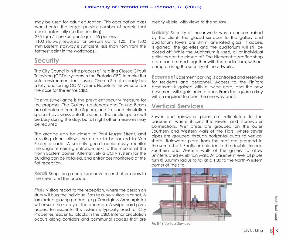
Vertical ServicesSewer and rainwater pipes are reticulated to the basement, where it joins the sewer- and stormwater connections. Wet areas are grouped on the outer Southern and Western walls of the Flats, where sewer pipes are grouped through horizontal ducts to vertical shafts. Rainwater pipes from the roof are grouped in the same shaft. Shafts are hidden in the double-skinned Southern and Western walls of the gallery to allow uninterrupted exhibition walls. At basement level all pipes turn @ 300mm radius to fall at a 1:80 to the North-Western corner of the site.
Fig 8-16 Vertical Services
UUnniivveerrssiittyy ooff PPrreettoorriiaa eettdd –– PPiieennaaaarr,, RR ((22000055))

tech
nica
l rep
ort
city building 8 10
technical report
city building 8 11
AuditoriumThe Auditorium is constructed as a 200 mm reinforced cast in-situ concrete shell. The massive structure enables the outer wall to be an effective beam. This allows for an irregular column grid, which is necessary for vehicular movement in the basement below.
Parapet walls are ‘folded over’ to hide and protect the edging of the bitumen sheet waterproofing. The waterproofing is further protected with 500x500 concrete-paving tiles laid on patent adjustable underlay pads. Multiple coloured concrete tiles will be laid randomly to create a ‘tapestry’, framed by the oversized parapet walls. This decision was made to avoid a potential eyesore due to the visibility of the roof from the flats and
circulation spaces. The shell provides acoustic insulation from noisy Paul Kruger Street. An acoustic corridor with highly absorptive panels will block potential noise created from the arcade. The auditorium is slanted to ensure that all rows will have a view to the speaker, and that sound is not blocked. The stage area and the back third of the auditorium will be covered with sound absorptive panels to prevent sound reflected back to the source, e.g. speaker/performer, while the rest will be covered in reflective panels to maximise the spread of sound waves through the auditorium. A sound engineer will be responsible for the detail design of the sound panels.
Fig 8-17 Auditorium section Fig 8-18 Concept sketch of planter use in the building
UUnniivveerrssiittyy ooff PPrreettoorriiaa eettdd –– PPiieennaaaarr,, RR ((22000055))

tech
nica
l rep
ort
city building 8 10
technical report
city building 8 11
Structural PlantersThe harsh environment of the city with hard surfaces will require tough indigenous species. Evergreen species were chosen that give deep shade, e.g. the Paperbark Thorn with its large canopy. Deciduous trees show the change of seasons on the square, e.g. the Coral tree with its red flowers in spring, and deep green leaves in Summer. Proposed species include:
Elevated Residential BlockThe double-storey elevated block with a clear span of 14 m is elevated 12m above the lowest level of the square. To overcome this a 800mm deep reinforced concrete beam is cast-in-situ between 450 diameter reinforced concrete columns. The columns are stabilized laterally through steel cross bracing, allowing reasonably slender columns. The two storeys are supported with separate beams. Floor slabs are positioned at the bottom of the beams, so that the structural element becomes part of the outer wall. A redbrick outer skin is glued to the exterior of the beam so that no apparent structure remains visible from the square below.
Deciduous treesCoral tree Erythrina lysistemon Witstinkhout Celtis africanaPaperbark Thorn Acacia sieberana woodii Evergreen treesOlienhout trees Olea africana
Fig 8-19 Planter Detail
Fig 8-21 Elevated Block Structure. Columns on the right are afforded lateral support through Auditorium under
To achieve effective growth cast in-situ structural planters were designed that can hold over 2 cubic meters of soil. Planters are present in the arcade, the gallery entrance foyer and the auditorium foyer. They become beacons of important places in the building, and can be decorated with mosaic tiles. The planters are imposing structures, and mosaic work could help to lighten the appearance of the form.
Fig 8-20 Concept Sketch
UUnniivveerrssiittyy ooff PPrreettoorriiaa eettdd –– PPiieennaaaarr,, RR ((22000055))