Single-Stage AC/DC Single-Inductor Multiple-Output LED Drivers · single stage. Therefore, diode in...
15
0885-8993 (c) 2015 IEEE. Personal use is permitted, but republication/redistribution requires IEEE permission. See http://www.ieee.org/publications_standards/publications/rights/index.html for more information. This article has been accepted for publication in a future issue of this journal, but has not been fully edited. Content may change prior to final publication. Citation information: DOI 10.1109/TPEL.2015.2496247, IEEE Transactions on Power Electronics 1 Abstract— Various AC/DC LED driver topologies have been proposed to meet the challenges of achieving a compact, efficient, low-cost and robust multi-string LED lighting system. These LED drivers typically employ a two-stage topology to realize the functions of AC/DC rectification and independent current control of each LED string. The choice of having two stage conversions involves additional hardware components and a more complicated controller design process. Such two-stage topologies suffer from a higher system cost, increased power loss, and large form factor. In this paper, a single-stage AC/DC single-inductor multiple-output (SIMO) LED driver is proposed. It uses only one single inductor and N+1 active power switches (N being the number of LED strings) with reduced component count and smaller form factor. The proposed driver can achieve both functions of AC/DC rectification with a high power factor and precise independent current control of each individual LED string simultaneously. A prototype of an AC/DC single-inductor triple-output (SITO) LED driver is constructed for verification. Experimental results corroborate that precise and independent current regulation of each individual LED string is achievable with the proposed driver. A power factor of above 0.99 and a peak efficiency of 89% at 30 W rated output power are attainable. Index Terms— Single-inductor multiple-output (SIMO), color control, lighting system, LED, power factor control. I. INTRODUCTION Light-emitting-diodes (LED) are increasingly gaining acceptance in lighting industry with a growing list of applications, such as general, decorative and display lighting applications [1]–[6]. The four major factors supporting their popularity are (i) preponderant long lifetime; (ii) mercury free Manuscript received Apr 09, 2015. This work is supported by the Hong Kong Research Grant Council under Theme-based Research Project: T22-715/12N. Guo Yue is with the Department of Electrical & Electronic Engineering, The University of Hong Kong (email: [email protected]). Sinan Li is with the Department of Electrical & Electronic Engineering, The University of Hong Kong (email: [email protected]). Albert T. L. Lee is with the Department of Electrical & Electronic Engineering, The University of Hong Kong (email: [email protected]). S. C. Tan is with the Department of Electrical & Electronic Engineering, The University of Hong Kong (email: [email protected]). C. K. Lee is with the Department of Electrical & Electronic Engineering, The University of Hong Kong (email: [email protected]). S.Y. R. Hui is with the Department of Electrical & Electronic Engineering, The University of Hong Kong (email: [email protected]) and Imperial College London (e-mail: [email protected]). and environmental friendly; (iii) high luminous efficiency; and (iv) flexibility to perform color mixing and dimming control [7]-[11]. Depending on the specific application requirements, the LED can either be arranged in series as a single string (or a single LED chip), or in parallel forming a multi-string structure (for medium and high power applications). Many LED drivers achieving small form factor and low cost have been proposed for the single LED chip/string applications [12]–[14]. However, achieving a compact and low-cost LED driver design is challenging for applications where multiple parallel LED strings are needed. This is because extra functionalities such as current balancing, individual string current regulation, or open/short circuit fault protection are typically demanded in such multi-string LED systems. For instance, in high power applications, such as streetlight and large-scale LCD panels, current sharing between strings is crucial for providing an evenly distributed light output and heat. Most importantly, if the current imbalance causes one or more LED strings to exceed their rated current values, the lifetime of the LED strings will be drastically reduced [15]– [19]. In color mixing applications, such as RGB LED lamp and LED-backlit LCD display, fast and precise current control of the red, green and blue LEDs should be guaranteed [20]–[22]. Basically, these functionalities, i.e., current sharing, individual string regulations, and/or open/short circuit fault protection, can be simultaneously achieved if each of the string current is regulated independently. In this way, current sharing can be simply realized by assigning a common current reference for all strings, while individual current regulation is accomplished by assigning a different reference command for each string. Several solutions for driving multi-string LED systems with independent current control have been proposed. They can be broadly classified into two types, as shown in Fig. 1(a) and (b). (a) Single-Stage AC/DC Single-Inductor Multiple-Output LED Drivers Yue Guo, Sinan Li, Member, IEEE, Albert T. L. Lee, Member, IEEE, Siew-Chong Tan, Senior Member, IEEE, C. K. Lee, Senior Member, IEEE, S. Y. (Ron) Hui, Fellow, IEEE
Transcript of Single-Stage AC/DC Single-Inductor Multiple-Output LED Drivers · single stage. Therefore, diode in...

0885-8993 (c) 2015 IEEE. Personal use is permitted, but republication/redistribution requires IEEE permission. See http://www.ieee.org/publications_standards/publications/rights/index.html for more information.
This article has been accepted for publication in a future issue of this journal, but has not been fully edited. Content may change prior to final publication. Citation information: DOI 10.1109/TPEL.2015.2496247, IEEETransactions on Power Electronics
1
Abstract— Various AC/DC LED driver topologies have
been proposed to meet the challenges of achieving a compact, efficient, low-cost and robust multi-string LED lighting system. These LED drivers typically employ a two-stage topology to realize the functions of AC/DC rectification and independent current control of each LED string. The choice of having two stage conversions involves additional hardware components and a more complicated controller design process. Such two-stage topologies suffer from a higher system cost, increased power loss, and large form factor. In this paper, a single-stage AC/DC single-inductor multiple-output (SIMO) LED driver is proposed. It uses only one single inductor and N+1 active power switches (N being the number of LED strings) with reduced component count and smaller form factor. The proposed driver can achieve both functions of AC/DC rectification with a high power factor and precise independent current control of each individual LED string simultaneously. A prototype of an AC/DC single-inductor triple-output (SITO) LED driver is constructed for verification. Experimental results corroborate that precise and independent current regulation of each individual LED string is achievable with the proposed driver. A power factor of above 0.99 and a peak efficiency of 89% at 30 W rated output power are attainable. Index Terms— Single-inductor multiple-output (SIMO), color control, lighting system, LED, power factor control.
I. INTRODUCTION Light-emitting-diodes (LED) are increasingly gaining
acceptance in lighting industry with a growing list of applications, such as general, decorative and display lighting applications [1]–[6]. The four major factors supporting their popularity are (i) preponderant long lifetime; (ii) mercury free
Manuscript received Apr 09, 2015. This work is supported by the Hong
Kong Research Grant Council under Theme-based Research Project: T22-715/12N. Guo Yue is with the Department of Electrical & Electronic Engineering, The University of Hong Kong (email: [email protected]). Sinan Li is with the Department of Electrical & Electronic Engineering, The University of Hong Kong (email: [email protected]). Albert T. L. Lee is with the Department of Electrical & Electronic Engineering, The University of Hong Kong (email: [email protected]). S. C. Tan is with the Department of Electrical & Electronic Engineering, The University of Hong Kong (email: [email protected]). C. K. Lee is with the Department of Electrical & Electronic Engineering, The University of Hong Kong (email: [email protected]). S.Y. R. Hui is with the Department of Electrical & Electronic Engineering, The University of Hong Kong (email: [email protected]) and Imperial College London (e-mail: [email protected]).
and environmental friendly; (iii) high luminous efficiency; and (iv) flexibility to perform color mixing and dimming control [7]-[11]. Depending on the specific application requirements, the LED can either be arranged in series as a single string (or a single LED chip), or in parallel forming a multi-string structure (for medium and high power applications). Many LED drivers achieving small form factor and low cost have been proposed for the single LED chip/string applications [12]–[14]. However, achieving a compact and low-cost LED driver design is challenging for applications where multiple parallel LED strings are needed. This is because extra functionalities such as current balancing, individual string current regulation, or open/short circuit fault protection are typically demanded in such multi-string LED systems.
For instance, in high power applications, such as streetlight and large-scale LCD panels, current sharing between strings is crucial for providing an evenly distributed light output and heat. Most importantly, if the current imbalance causes one or more LED strings to exceed their rated current values, the lifetime of the LED strings will be drastically reduced [15]–[19]. In color mixing applications, such as RGB LED lamp and LED-backlit LCD display, fast and precise current control of the red, green and blue LEDs should be guaranteed [20]–[22]. Basically, these functionalities, i.e., current sharing, individual string regulations, and/or open/short circuit fault protection, can be simultaneously achieved if each of the string current is regulated independently. In this way, current sharing can be simply realized by assigning a common current reference for all strings, while individual current regulation is accomplished by assigning a different reference command for each string.
Several solutions for driving multi-string LED systems with independent current control have been proposed. They can be broadly classified into two types, as shown in Fig. 1(a) and (b).
(a)
Single-Stage AC/DC Single-Inductor Multiple-Output LED Drivers
Yue Guo, Sinan Li, Member, IEEE, Albert T. L. Lee, Member, IEEE, Siew-Chong Tan, Senior Member, IEEE, C. K. Lee, Senior Member, IEEE, S. Y. (Ron) Hui, Fellow, IEEE
0885-8993 (c) 2015 IEEE. Personal use is permitted, but republication/redistribution requires IEEE permission. See http://www.ieee.org/publications_standards/publications/rights/index.html for more information.
This article has been accepted for publication in a future issue of this journal, but has not been fully edited. Content may change prior to final publication. Citation information: DOI 10.1109/TPEL.2015.2496247, IEEETransactions on Power Electronics
2
(b)
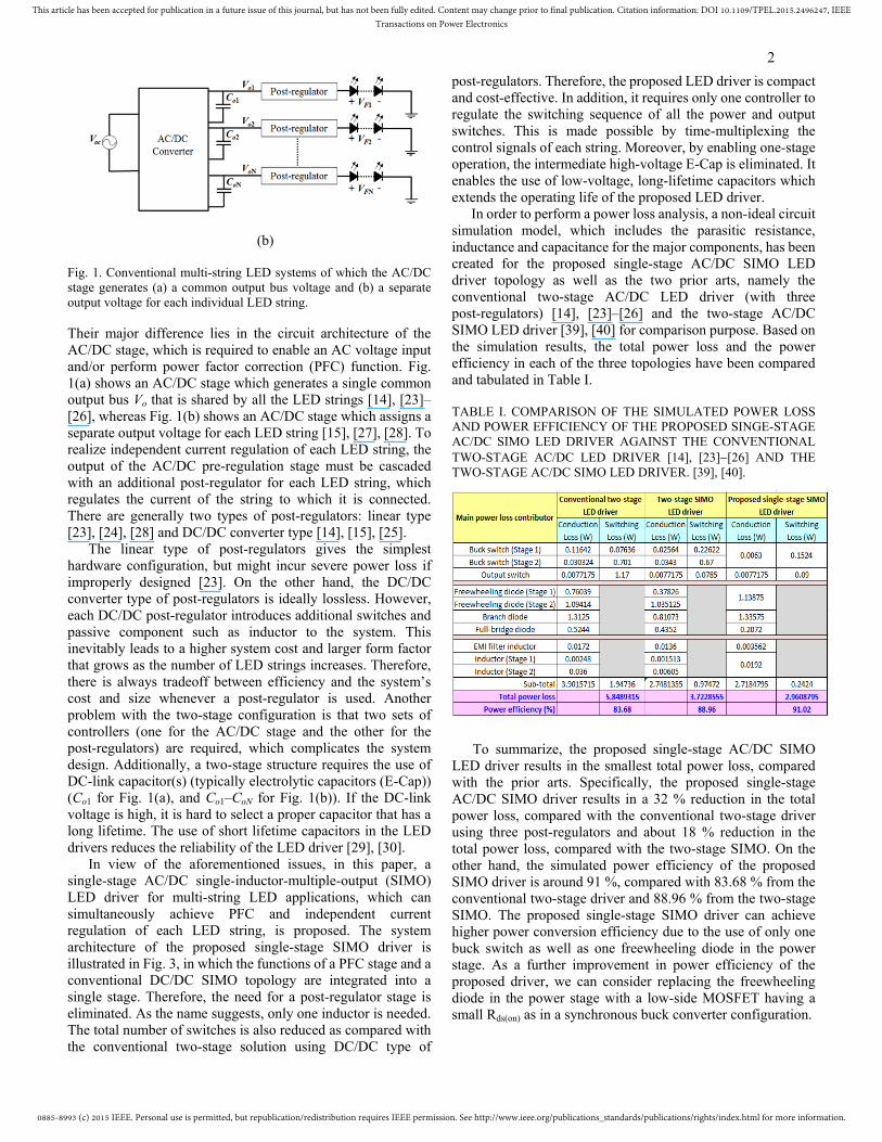
Fig. 1. Conventional multi-string LED systems of which the AC/DC stage generates (a) a common output bus voltage and (b) a separate output voltage for each individual LED string. Their major difference lies in the circuit architecture of the AC/DC stage, which is required to enable an AC voltage input and/or perform power factor correction (PFC) function. Fig. 1(a) shows an AC/DC stage which generates a single common output bus Vo that is shared by all the LED strings [14], [23]–[26], whereas Fig. 1(b) shows an AC/DC stage which assigns a separate output voltage for each LED string [15], [27], [28]. To realize independent current regulation of each LED string, the output of the AC/DC pre-regulation stage must be cascaded with an additional post-regulator for each LED string, which regulates the current of the string to which it is connected. There are generally two types of post-regulators: linear type [23], [24], [28] and DC/DC converter type [14], [15], [25].
The linear type of post-regulators gives the simplest hardware configuration, but might incur severe power loss if improperly designed [23]. On the other hand, the DC/DC converter type of post-regulators is ideally lossless. However, each DC/DC post-regulator introduces additional switches and passive component such as inductor to the system. This inevitably leads to a higher system cost and larger form factor that grows as the number of LED strings increases. Therefore, there is always tradeoff between efficiency and the system’s cost and size whenever a post-regulator is used. Another problem with the two-stage configuration is that two sets of controllers (one for the AC/DC stage and the other for the post-regulators) are required, which complicates the system design. Additionally, a two-stage structure requires the use of DC-link capacitor(s) (typically electrolytic capacitors (E-Cap)) (Co1 for Fig. 1(a), and Co1–CoN for Fig. 1(b)). If the DC-link voltage is high, it is hard to select a proper capacitor that has a long lifetime. The use of short lifetime capacitors in the LED drivers reduces the reliability of the LED driver [29], [30].
In view of the aforementioned issues, in this paper, a single-stage AC/DC single-inductor-multiple-output (SIMO) LED driver for multi-string LED applications, which can simultaneously achieve PFC and independent current regulation of each LED string, is proposed. The system architecture of the proposed single-stage SIMO driver is illustrated in Fig. 3, in which the functions of a PFC stage and a conventional DC/DC SIMO topology are integrated into a single stage. Therefore, the need for a post-regulator stage is eliminated. As the name suggests, only one inductor is needed. The total number of switches is also reduced as compared with the conventional two-stage solution using DC/DC type of
post-regulators. Therefore, the proposed LED driver is compact and cost-effective. In addition, it requires only one controller to regulate the switching sequence of all the power and output switches. This is made possible by time-multiplexing the control signals of each string. Moreover, by enabling one-stage operation, the intermediate high-voltage E-Cap is eliminated. It enables the use of low-voltage, long-lifetime capacitors which extends the operating life of the proposed LED driver.
In order to perform a power loss analysis, a non-ideal circuit simulation model, which includes the parasitic resistance, inductance and capacitance for the major components, has been created for the proposed single-stage AC/DC SIMO LED driver topology as well as the two prior arts, namely the conventional two-stage AC/DC LED driver (with three post-regulators) [14], [23]–[26] and the two-stage AC/DC SIMO LED driver [39], [40] for comparison purpose. Based on the simulation results, the total power loss and the power efficiency in each of the three topologies have been compared and tabulated in Table I. TABLE I. COMPARISON OF THE SIMULATED POWER LOSS AND POWER EFFICIENCY OF THE PROPOSED SINGE-STAGE AC/DC SIMO LED DRIVER AGAINST THE CONVENTIONAL TWO-STAGE AC/DC LED DRIVER [14], [23]−[26] AND THE TWO-STAGE AC/DC SIMO LED DRIVER. [39], [40].
To summarize, the proposed single-stage AC/DC SIMO LED driver results in the smallest total power loss, compared with the prior arts. Specifically, the proposed single-stage AC/DC SIMO driver results in a 32 % reduction in the total power loss, compared with the conventional two-stage driver using three post-regulators and about 18 % reduction in the total power loss, compared with the two-stage SIMO. On the other hand, the simulated power efficiency of the proposed SIMO driver is around 91 %, compared with 83.68 % from the conventional two-stage driver and 88.96 % from the two-stage SIMO. The proposed single-stage SIMO driver can achieve higher power conversion efficiency due to the use of only one buck switch as well as one freewheeling diode in the power stage. As a further improvement in power efficiency of the proposed driver, we can consider replacing the freewheeling diode in the power stage with a low-side MOSFET having a small Rds(on) as in a synchronous buck converter configuration.

0885-8993 (c) 2015 IEEE. Personal use is permitted, but republication/redistribution requires IEEE permission. See http://www.ieee.org/publications_standards/publications/rights/index.html for more information.
This article has been accepted for publication in a future issue of this journal, but has not been fully edited. Content may change prior to final publication. Citation information: DOI 10.1109/TPEL.2015.2496247, IEEETransactions on Power Electronics
3
II. AC/DC SINGLE-INDUCTOR MULTIPLE-OUTPUT LED DRIVERS
A. Existing AC/DC SIMO LED Driver
There is growing interest in using DC/DC SIMO converters for multi-string LED applications due to their reduced cost and smaller form factor. A single-inductor dual-output (SIDO) converter with time-multiplexing control scheme operating in DCM is first reported in [31], [32]. Extending from SIDO, a DC/DC SIMO parallel string LED driver operating in DCM is recently reported in [33]-[38]. All of these reported SIMO converters can only realize DC/DC conversion, and a stable DC input is typically required. To accommodate an AC voltage input, e.g. a 110 V, 60 Hz AC mains, a DC/DC SIMO LED driver is often cascaded behind an AC/DC front-end stage [39], [40], as shown in Fig. 2, again forming a two-stage configuration, which is similar to that given in Fig. 1.
Fig. 2. System architecture of the existing two-stage AC/DC SIMO LED driver.
In [39], the AC/DC front-stage is simply a diode bridge rectifier with a large capacitor. An unregulated DC voltage is produced without performing any PFC. Such a configuration is only useful for low-power LED applications, of which the PF requirement is less stringent [41], [42]. Also, the SIMO converter in [40] is operating in continuous conduction mode (CCM) and suffers from cross-regulation issues. Therefore, individual current regulation of LED strings is unviable, and only current sharing function is performed. On the other hand, in [40], a boost PFC converter is implemented as the AC/DC front-stage converter, providing a well-regulated DC voltage and a high PF. Nevertheless, by employing a two-stage configuration, these existing AC/DC SIMO LED drivers inherently have similar demerits as those described in Fig. 1.
B. Proposed Single-Stage AC/DC SIMO LED Driver
Fig. 3 shows the configuration of the proposed single-stage SIMO LED driver.
Fig. 3. System architecture of the proposed single-stage AC/DC SIMO LED driving system.
Unlike existing AC/DC SIMO LED drivers that are configured as shown in Fig. 2, the proposed AC/DC SIMO LED driver can directly drive multiple LED strings off an AC voltage source in a single stage, without an intermediate DC-link. Both PFC and independent regulation of string currents are simultaneously viable. This is possible through proper component integration of a PFC stage and a DC/DC SIMO converter. For example, if a DCM buck converter is adopted for the PFC stage (Fig. 4(a)), and a buck-type DC/DC SIMO is selected for the SIMO stage (Fig. 4(b)), by integrating their main power switch Sa and Sa’, freewheeling diode Da and Da’, and inductor L and L’, a single-stage buck-type AC/DC SIMO driver can be obtained as shown in Fig. 4(c).
(a) (b)
(c)
Fig. 4. Derivation of a buck-type single-stage AC/DC SIMO LED driver. (a) A DCM buck PFC converter. (b) A buck-type DC/DC SIMO converter. (c) The derived buck-type single-stage AC/DC SIMO LED driver.
By employing a time-multiplexing control scheme, at any instance in time, the LED driver depicted in Fig. 4(c) can be operated to act as a single-input single-output DCM buck converter. Since a DCM buck converter is naturally an emulated resistor at low frequencies [43], the averaged input current of the LED driver over each switching period is inherently proportional to the line voltage. As a result, the original DC/DC SIMO converter can be readily turned into a single-stage AC/DC SIMO driver integrated with PFC function through minor hardware modifications including the addition of the front-end diode rectifier. In contrast to all previous methods that are two-staged-based, the driver in Fig. 3 and Fig. 4(c) requires no E-Cap between the diode bridge and the SIMO stage. Clearly, the removal of a short lifetime high voltage E-Cap extends the operating lifetime of the proposed LED driver. Also, by operating the proposed SIMO driver in DCM,
+

0885-8993 (c) 2015 IEEE. Personal use is permitted, but republication/redistribution requires IEEE permission. See http://www.ieee.org/publications_standards/publications/rights/index.html for more information.
This article has been accepted for publication in a future issue of this journal, but has not been fully edited. Content may change prior to final publication. Citation information: DOI 10.1109/TPEL.2015.2496247, IEEETransactions on Power Electronics
4
cross-regulation can virtually be eliminated as the individual LED strings are fully decoupled from one another.
III. OPERATING PRINCIPLES OF THE PROPOSED SINGLE-STAGE AC/DC SIMO LED DRIVER
A. Operating Modes
A single-inductor triple-output (SITO) AC/DC buck converter as shown in Fig. 5 is used for the sake of our discussions.
Fig. 5. Complete circuit diagram with three LED strings.
As shown in Fig. 5, a total of four switches, i.e., one main switch Sa and three output switches S1–S3, are used in this converter. Lf and Cf forms the input EMI filter, Cd is the high-frequency filter capacitor, Da is the freewheeling diode, and L is the main inductor. Di is the branch diode in the ith LED string for preventing reverse flow of the branch current. Coi and Rsi are the output capacitor and sensing resistor of the ith LED string. The AC input voltage is Vac, the input voltage to the buck converter is represented by Vin and the three output voltages are Vo1–Vo3. IL is the inductor current and Ibranch1–Ibranch3 are the branch currents that flows through the respective output switches. The ideal waveforms of Sa, S1–S3, IL, and Ibranch1–Ibranch3 are shown in Fig. 6(a), where Ts represents the switching period of the main switch Sa.
It can be seen that the proposed AC/DC SIMO converter operates in DCM where IL always returns to zero at the end of each switching cycle. Fig. 6(b) depicts the control sequence of the SITO AC/DC converter under normal operations. In three switching cycles (0–3Ts), there are a total of nine control sequences which can be categorized into the following three distinctive modes of operation.
• Mode 1 (t0–t1): Main switch Sa is ON and freewheeling diode Da is OFF. The inductor current IL increases at a rate of (Vin−Vo1)/L. The output switch S1 is ON and S2 and S3 are OFF since only the first output is enabled. This corresponds to (1−1), (2−1), and (3−1) in Fig. 6(b).
• Mode 2 (t1–t2): Sa is OFF and Da is ON. IL decreases linearly at a rate of Vo1/L. At t2, IL drops to 0 and Mode 2 ends. This
corresponds to (1−2), (2−2), and (3−2) in Fig. 6(b). • Mode 3 (t2–t3): Both Sa and Da are OFF. IL remains at zero
during this idle period. In order to reduce the switching loss, for example, S1 can be turned off with zero-current switching (ZCS) and S2 can be turned on with ZCS during this interval. This corresponds to (1−3), (2−3), and (3−3) in Fig. 6(b).
(a)
(b)
Fig. 6. (a) Timing diagram of the main switch Sa and output switches S1−S3, inductor current IL and branch currents Ibranch1–Ibranch3 and (b) control sequence of the proposed AC/DC SITO LED driver. The same process is repeated in the next two switching periods for the second and third output in which S1 is OFF and S2, S3 take turns to be ON. The energy is transferred from the inductor to the three outputs in a time-interleaved manner. The same control sequence can also be scaled conveniently to N outputs, where N is the total number of LED strings. The output switch corresponding to each LED string, namely S1, S2, …, SN, is ON only during one of the N switching cycles. The output switch is OFF during the remaining (N−1) switching cycles.

0885-8993 (c) 2015 IEEE. Personal use is permitted, but republication/redistribution requires IEEE permission. See http://www.ieee.org/publications_standards/publications/rights/index.html for more information.
This article has been accepted for publication in a future issue of this journal, but has not been fully edited. Content may change prior to final publication. Citation information: DOI 10.1109/TPEL.2015.2496247, IEEETransactions on Power Electronics
5
B. Control Schemes
The control circuit of the proposed AC/DC SITO buck LED driver is a specialized time multiplexed controller as shown in Fig. 5. According to the operating principles described in Section A, the on-instant of Sa should be synchronized with respective output switches S1–S3. The synchronization is realized by the 75 kHz time synchronization block. A more detailed explanation will be given in Section C. The averaged current of each LED string is controlled by the respective control loop that compares the current-sense voltage Vsi (which is equal to the LED current amplified by 10 times) to a reference Irefi. The error signal VEAi is compensated by a PI compensator and modulated by a PWM modulator to give the on-time duty ratio di and command Sa. The signals that are provided by the three phase clock generator are used to command S1–S3 and select one of the three channels of the MUX. In practice, there will be a total of three feedback loops, one for each LED string. The three PI controllers take turns to use the analog comparator, which means that in any instance, the circuit effectively has only one set of PI controller in operation. In addition, with reference to [43], by operating the system in DCM, the load is essentially an emulated resistor connected to the converter input. Although the emulated resistor, which is determined by the duty cycle di, is different in three LED strings, in any instance only one emulated resistor will be connected to the converter input, which means that the PFC can be achieved. Fig. 7 shows the timing diagram of the time-multiplexed PWM control using three distinct-colored LEDs to represent different loading conditions among the three LED strings.
Fig. 7. Timing diagrams for different PWM duty ratios using three distinct-colored LEDs.
Note that for different loading conditions and/or with different current reference command, the PI outputs are different and thus the PWM duty ratios for each string are different. In order to minimize the hardware resources, the outputs of the PI compensators are time-multiplexed together while sharing a common PWM modulator. This enables the subsequent logic elements beyond the PI compensators to be time shared among all the SITO outputs. In the SITO topology, the use of time-interleaving control with multiple energizing phases means that each of the LED string is independently driven and is decoupled from the other strings with minimal cross-interference. The current in each individual LED string
can be controlled separately by assigning a unique current reference in each LED string. It can be expected that, with different loading conditions and current reference commands, the inductor current IL for respective string will have different (rising and falling) slopes and durations. This phenomenon is shown in Fig. 6(a) and is verified later by experimental measurement. In addition, current balancing, which is a special case of independent current control, can be realized by using the same current reference signal across all the LED strings without the need for additional post-regulator circuits.
C. 75 kHz Timing Synchronization Block
The timing of Sa and S1–S3 is synchronized using a 555 timer operating in monostable state. The detailed 75 kHz timing synchronization block is illustrated in Fig. 8.
Fig. 8. 555 timer operating in monostable state to generate linear ramp Vsaw and pulse train Vpulse.
The bias voltage of the BJT T is set by RT2 and RT3, and RT1
serves to limit the current flowing through T to charge up capacitor CT1. The voltage across CT1 is
1 1
1 ,T
T T
CTQ IV tC C
= = (1)
where Q is the charge of CT1, and IT is the current through the BJT. Under the given configuration, the 555 timer operates to generate a linear ramp Vsaw at pin 6. The output pin 3 generates a trigger pulse which dips every time CT1 is discharged. By inverting this trigger pulse, a pulse train Vpulse, which is synchronized with Vsaw, is obtained. Vsaw is fed to the PWM comparator and Vpulse is used to generate the three phase clock to enable the SITO operation.
IV. PARAMETER DESIGN OF THE SIMO LED DRIVER
A. Inductor Design
To minimize the size of the inductor and simplify the controller design for PFC, the converter should be operated in DCM. Also, the current ripple in the inductor L should be limited to reduce the current stress of the power switches. Thus, the buck main inductor should neither be too large nor too small.

0885-8993 (c) 2015 IEEE. Personal use is permitted, but republication/redistribution requires IEEE permission. See http://www.ieee.org/publications_standards/publications/rights/index.html for more information.
This article has been accepted for publication in a future issue of this journal, but has not been fully edited. Content may change prior to final publication. Citation information: DOI 10.1109/TPEL.2015.2496247, IEEETransactions on Power Electronics
6
Fig. 9. An equivalent LED model which comprises of an ideal diode DLED, small signal resistor RLED and threshold voltage Vth. Fig. 9 shows an equivalent LED model, which comprises a series connection of an ideal diode DLED, a resistor RLED and a threshold voltage Vth. Based on this model, the parameters of the red (R), green (G), and blue (B) LEDs [44] used in the experiments are tabulated in Table II.
TABLE II. PARAMETERS OF THE RGB LEDS.
Type Luxeon Rebel Red
Luxeon Rebel Green
Luxeon Rebel Blue
Equivalent Resistance RLED
(Ω) 4 6 6
Rated Current ILED (mA) 350 350 350
Threshold Voltage Vth (V) 0.7 0.8 0.85
Forward Voltage VF (V) 2.1 2.9 2.95
Rated Power PLED (W) 0.735 1.015 1.0325
Fig. 10. Inductor voltage waveform of a buck converter in CCM operation.
Fig. 10 shows the inductor voltage waveform of a buck
converter in CCM at steady state. Using inductor volt-second balance,
( ) (1 ) 0in oi i s oi i sV V d T V d T− − − = , (2)
where Vin is the input voltage of the buck converter, Voi is the output voltage of the ith LED string, as described in Fig. 5, and di is the duty ratio of the ith LED string as shown in Fig. 7. The output voltage of the ith LED string is
.oi i inV d V= (3)
In the first switching interval, the increasing rate of inductor current ILi is
( ) ,in oi
i i
Li LidI V t V Vdt L L
−= = (4)
where Li is the inductance when the ith string is considered.The peak-to-average current ripple is defined as
., 2in oi
i s
i
Li paV VI d T
L−
∆ = (5)
In steady-state condition, the DC component of the buck capacitor current should be zero. Therefore, the DC component of the buck inductor current is
,oi thiLEDi
LEDi
LiV WVI I
WR−
= = (6)
where W is the number of LEDs in one string, and ILEDi, Vthi and RLEDi are respectively the rated LED current, the LED threshold voltage, and the LED equivalent resistance in the ith string. If the system operates in DCM, then ILi < ∆ILi, where ∆ILi represents the maximum inductor current ripple when the buck converter operates in boundary conduction mode (BCM), i.e.,
.2
oi thi in oii s
LEDi i
V WV V V d TWR L− −
< (7)
where di = Voi/Vin in BCM. Hence, the minimum value of Li is
_ min
( ) ( ) ,2( ) 2( )
in oi LEDi in oi LEDi oii i s s
oi thi oi thi in
V V WR V V WR VL d T TV WV V WV V− −
= =− −
(8)
and the upper boundary of the main inductance is given by
_ minmin{ }, 1,2,3,... .iL L i W< = (9)
On the other hand, the lower boundary can be obtained by considering the maximum allowable inductor current ripple ΔIL_max using
_ max .in oii s L
i
LiV VI d T I
L−
∆ = ≤ ∆ (10)
In DCM operation, we have
_
2
,( ) LEDi
e i i
rmsV PR d
= (11)
where Vrms is the RMS value of Vin, Re_i (d) is the equivalent resistance emulated by the DCM buck converter for the ith LED string given by [43]
_ 2
2( ) ,ii
i s
e iLR d
d T= (12)
and PLEDi is the power consumed by the LED load in the ith string given by
,LEDi Fi LEDiP WV I= (13)

0885-8993 (c) 2015 IEEE. Personal use is permitted, but republication/redistribution requires IEEE permission. See http://www.ieee.org/publications_standards/publications/rights/index.html for more information.
This article has been accepted for publication in a future issue of this journal, but has not been fully edited. Content may change prior to final publication. Citation information: DOI 10.1109/TPEL.2015.2496247, IEEETransactions on Power Electronics
7
where VFi is the forward voltage of LED in the ith string. From (11) and (12), the duty cycle di can be represented by
_
2
2 2 .( )
i i LEDii
e i i s srms
L L PdR d T V T
= = (14)
By substituting (14) into (10), the maximum value of Li is
_ max
_ max
22
2( ) ,in oi LEDi si
L rms
V V P TLI V−
=∆
(15)
and the lower boundary of the main inductance is given by
_ maxmax{ }, 1,2,3,... .iL L i W≥ = (16)
B. Output Capacitor Design
For each LED string, an output capacitor Coi is separately required. The design of the capacitors can be performed independently since the operation of each string is decoupled. The design approach is the same as that for a DC-link capacitor in conventional AC/DC rectifying systems since the employed output capacitors have to perform the same functions of AC energy storage and switching frequency filtering. This is different from that of the DC/DC SIMO LED driver in which the output capacitor is designed to handle only switching ripples.
If ΔVi = kVoi, where Voi is the average output voltage in string i, ΔVi is the peak output voltage ripple, and k is the ripple factor that defines the allowable peak voltage ripple, then with reference to [43], the lower limit for Coi is
2 ,2
LEDi acoi
oi
P TCkV π
≥ × (17)
where Tac=1/(60 Hz).
C. Small–Signal Analysis and Controller Design
Due to the time-multiplex arrangement of the three controllers, only one output is effective at any instance. Therefore, the controller can be designed independently. Take one string as an example. Fig. 11 shows the small-signal block diagram of one string. Essentially, the controlled power plant is a buck converter operating in DCM. A straight-forward way to determine the low frequency small-signal control-to-output transfer function of the buck converter in the ith string, denoted by GBuck_i(s), is to let the main inductance L tend to zero. With reference to [43], GBuck_i(s) is given by
_
ˆ 0
2 1 1ˆ 2( ) ,ˆ
1 2(1 )
oi i
oi i i LEDiBuck i
ig
i
i LEDi oi
v
V Mi d M WRG s sd
MM WR C
=
−× ×
−= =
+−
−
(18)
where Mi is the DCM conversion ratio of the ith LED string
given by
2
2 .81 1
oii
in i
LEDi i s
VMV L
WR d T
= =+ +
(19)
A simple PI controller is used as the compensator. In Fig. 11, which shows the small-signal control block diagram, the transfer function of the compensator of the ith LED string is given by
_ _( ) ,p i int i
ci
sk kG s
s+
= (20)
where kp_i is the proportional gain and kint_i is the integral gain. Here, VM is the amplitude of the sawtooth carrier waveform and Hi(s) is the sensing gain for the ith string. The output of PI compensator ciV is fed into the PWM modulator with a gain of 1/VM in order to generate a duty ratio di. The averaged current in each LED string is determined by the corresponding current reference value Irefi(s).
Fig. 11. Small-signal block diagram of the ith string in the proposed closed-loop SIMO converter.
The loop gain Ti(s) of the system can be represented as
_
1( ) ( ) ( ) ( ).i ci Buck i i
M
T s G s G s H sV
= × × × (21)
By substituting (18) and (20) to (21), the loop gain becomes
_ _
2 1 12 1( ) ( ).
1 2(1 )
oi i
p i int i i LEDii
M
i
i LEDi oi
ii
V Msk k d M WRT s H sss V
MM WR C
−× ×
+ −= × × ×
+−
−
(22)
D. Design Example
The design parameters given in Table III are adopted for illustrative purpose. By substituting the values into (8), the upper limits of the inductance for the three different LED strings can be found as L1_min = 254 µH, L2_min = 336 µH, L3_min = 341 µH. According to (9), the upper limit of inductance will be L < 254 µH.
Next, by substituting the same design parameters into (15), the lower limit of inductance for the three LED strings can be found as L1_max = 3.52 µH, L2_max = 4.48 µH, L3_max = 4.53 µH. From (16), the lower limit of inductance is found as L ≥ 4.53 µH. Therefore, the range of inductance is 4.53 µH ≤ L ≤ 254 µH. In order to minimize the size of the main inductor to achieve a smaller overall form factor of the proposed LED

0885-8993 (c) 2015 IEEE. Personal use is permitted, but republication/redistribution requires IEEE permission. See http://www.ieee.org/publications_standards/publications/rights/index.html for more information.
This article has been accepted for publication in a future issue of this journal, but has not been fully edited. Content may change prior to final publication. Citation information: DOI 10.1109/TPEL.2015.2496247, IEEETransactions on Power Electronics
8
driver, L is selected to be 5 𝜇𝜇. However, for a practical design, more design margins of L are recommended to compensate for the operating transient, component tolerances, etc. Then, by referring to (17), the lower limits of Coi for the three LED strings are Co1 ≥ 902 µF, Co2 ≥ 653 µF, Co3 ≥ 642 µF. For illustration purpose, Co1, Co2, and Co3 are all chosen to be 1000 μF.
To demonstrate the controller design, string 1 (red LEDs) is chosen as an example. The input voltage Vin has a peak value of 110 2 V. With reference to Table II, it is desired to supply a regulated output voltage Vo1 = 14.7 V and LED current ILED1 = 350 mA. The first step is to determine the feedback gain H1(s). A 1 Ω resistor Rs1 is used as the current sensing resistor. The voltage of Rs1 will then be amplified by a factor of p = 10 using proportional amplifier, and compared with current reference Iref1. Hence, we have
1 1( ) 10.sH s R p= = (23)
By substituting the related parameters listed in Table III into (21), the open-loop transfer function of the system before compensation (when Gc1(s) =1) can therefore be written as
1 _1 1
1 56( ) ( ) ( ) .1
75
u Buck
M
T s G s H s sV= × × =
+ (24)
By setting |Tu1(jω)| = 1, the cross-over frequency fcu1 of the uncompensated loop gain Tu1(s) can be obtained as fcu1 = 0.668 kHz. The desired cross-over frequency of the loop gain after compensation T1(s) is chosen to be fc1 = (1/10)×fo = 2.5 kHz, where fo is the output switch frequency. From (24) at 2.5 kHz, the magnitude of Tu1(s) is
156| ( 2 2.5 ) | | | 11.46 .2 2.5 1
75
uT j k dBj kπ π× × = = −× ×
+ (25)
From (20), to obtain a unity loop gain at 2.5 kHz, the compensator should have a 2.5 kHz gain of 11.46 dB, which means that _1 _1
1
2 2.5| ( 2 2.5 ) | | | 11.46 .
2 2.5p int
c
j k k kG j k dB
j kπ
ππ
× × × +× × = =
× × (26)
By choosing kp_1 = 3.5, kint_1 can be calculated as kint_1 = 20755. Thus, the compensator transfer function Gc1(s) is
_1 _1
1
20755( ) 3.5 .p int
c
sk kG s
s s+
= = + (27)
Based on (24) and (27), the Bode plots of the open-loop gain before and after compensation as well as the compensator transfer function Gc1(s) can be plotted as shown in Fig. 12. From the figure, the phase margin is 70°, which indicates that the system is stable.
Fig. 12. Bode plots of loop gain T1(s) before and after compensation as well as the compensator transfer function Gc1(s).
V. EXPERIMENTAL VERIFICATION
A hardware prototype of the proposed single-stage AC/DC single-inductor three-output (SITO) LED driver has been constructed. Fig. 13 shows a photo of the prototype.
Fig. 13. Hardware prototype of the proposed single-stage AC/DC single-inductor three-output (SITO) LED driver.
Experiment verifications are performed based on the hardware prototype shown in Fig. 13 and the design specifications provided in Table III.

0885-8993 (c) 2015 IEEE. Personal use is permitted, but republication/redistribution requires IEEE permission. See http://www.ieee.org/publications_standards/publications/rights/index.html for more information.
This article has been accepted for publication in a future issue of this journal, but has not been fully edited. Content may change prior to final publication. Citation information: DOI 10.1109/TPEL.2015.2496247, IEEETransactions on Power Electronics
9
TABLE III. DESIGN SPECIFICATIONS.
Design Parameter Value Design Parameter Value
Input voltage Vac 110 V Rated LED Current ILED 350 mA
EMI Filter (Lf, Cf) 1 mH, 0.1 μF
Voltage Ripple Factor k 7%
Filter Capacitor Cd 0.1 μF Sensing Resistor Rs
1 Ω
Main Switch Frequency fs
75 kHz Power Inductor L 5 μH
Max. Current Ripple ΔiLmax
8 A Cross-over Frequency fc
2.5 kHz
Output Capacitor (Co1, Co2, Co3)
1000 μF
Same-colored LED
String 1: 7 Blue LEDs
String 2: 7 Blue LEDs
String 3: 7 Blue LEDs
Rated Output Voltage (Vo1, Vo2,
Vo3)
String 1: 14.7 V
Distinct-colored LED
String 1: 7 Red LEDs
String 2: 20.3 V
String 2: 7 Green LEDs
String 3: 20.7 V
String 3: 7 Blue LEDs
Table IV shows a list of components used in the experiment. The experiments involve two types of LED loads. In the first scenario, same-colored LEDs are used for the three strings, that is, each string consists of 7 blue LEDs. In the second scenario, distinct-colored LEDs are used for the three strings, that is seven red LEDs are assigned to the first string, seven green LEDs for the second string, and seven blue LEDs for the third string. Note that the current in the three strings in either scenario can be controlled independently to be identical or different.
TABLE IV. COMPONENT LIST.
Component Model no. Component Model no. Diode Bridge
Rectifier GBU10G-BP MUX CD74HC4051E
Main Switch (Sa)
IPW50R280CE Comparator AD8561ANZ
MOSFET Gate Driver IRS2101PBF Oscillator LM555CN/NOPB
Freewheeling and Branch
Diodes MUR1540G Operational
Amplifier OP340PA
Output Switches (S1,
S2, S3) IRFI4227PbF
Output Capacitor (Co1, Co2,
Co3)
UPX1V102MHD (long lifetime)
A. Cicruit Operating Principle
Fig. 14 shows the AC line voltage and input current waveforms using a 110 V 60 Hz AC source and same-colored LEDs as the load. It can be seen that the AC line voltage and the input current are essentially in phase and the power factor is measured as 0.99, thereby verifying the functionality of PFC.
Fig. 14. Measured waveforms of the AC line input voltage and current for 30 W output power using same-colored LEDs with a common current reference of 350 mA.
Fig. 15. Measured waveforms of IL and Ibranch1−Ibranch3 employing same-colored LEDs with identical LED current of 350 mA. Fig. 15 shows the full view of the inductor current IL and the three branch currents Ibranch1−Ibranch3 with same-colored LEDs and a common 350 mA reference current. The maximum current in each LED string peaks at around 7.5 A which falls within the design specification limit (i.e., ΔiLmax = 8 A). Figs. 16 to 18 show the close-up view of IL and Ibranch1–Ibranch3, and the corresponding driving signals of main switch Vdrive_main and output switches Vdrive_1−Vdrive_3 under different conditions. From Fig. 16, same-colored LEDs with a 350 mA common reference command are used. It shows that (i) the duty cycles of the PWM signal that drives the main switch Sa are similar for different LED strings; and (ii) the peak values of Ibranch1–Ibranch3 are the same. Also, Sa is ON in every switching cycle, but the output switch Si (where i = 1,2,3) is ON in every three switching cycles. Consequently, IL ramps up and down in each switching cycle but the branch current Ibranchi of each LED string appears every three switching cycles. In other words, IL is assigned to each of the three LED strings in a round-robin fashion. The experimental results verify the functionality of the SIMO topology and the time-multiplexed control method.
(a)

0885-8993 (c) 2015 IEEE. Personal use is permitted, but republication/redistribution requires IEEE permission. See http://www.ieee.org/publications_standards/publications/rights/index.html for more information.
This article has been accepted for publication in a future issue of this journal, but has not been fully edited. Content may change prior to final publication. Citation information: DOI 10.1109/TPEL.2015.2496247, IEEETransactions on Power Electronics
10
(b) Fig. 16. Close-up view of (a) driving signals of main switch Sa and output switches S1–S3 and (b) the corresponding IL and Ibranch1-Ibranch3 with same-colored LEDs and a common 350 mA reference command. Fig. 17 shows the “distinct-colored LEDs” scenario with a 350 mA common reference. It is important to note that the PWM duty ratio corresponding to each of the three LED strings is different. Also, the peak value of the branch current Ibranchi (also the peak inductor current) is also distinct among the three LED strings. On the other hand, Fig. 18 shows the “same-colored LEDs” scenario with different reference values. Similar to Fig. 17, the duty cycle of the PWM signal which drives Sa and the peak values of Ibranchi in three LED strings are different in every switching cycle.
(a)
(b) Fig. 17. Close-up view of (a) driving signals of main switch Sa and output switches S1–S3 and (b) the corresponding IL and Ibranch1-Ibranch3 with distinct-colored LEDs and a common 350 mA reference command.
(a)
(b) Fig. 18. Close-up view of (a) driving signals of main switch Sa and output switches S1–S3 and (b) the corresponding IL and Ibranch1-Ibranch3 using same-colored LEDs and with distinct reference current values (i.e., 250 mA, 350 mA, 450 mA) across the three LED strings. B. Current Balancing and Steady State Independent Current
Regulation
The averaged current in each of the three individual LED strings can be independently adjusted for the purpose of color-mixing and dimming. Also, in order to achieve brightness uniformity, current balancing of different LED strings is required. The waveforms for these two scenarios are illustrated in Fig. 19.
(a)

0885-8993 (c) 2015 IEEE. Personal use is permitted, but republication/redistribution requires IEEE permission. See http://www.ieee.org/publications_standards/publications/rights/index.html for more information.
This article has been accepted for publication in a future issue of this journal, but has not been fully edited. Content may change prior to final publication. Citation information: DOI 10.1109/TPEL.2015.2496247, IEEETransactions on Power Electronics
11
(b)
Fig. 19. Output current waveforms of the three LED strings using same-colored LEDs and with (a) 250 mA, 350 mA, 450 mA individual current control and (b) 350 mA current balancing condition. Fig. 19(a) shows the individual current control of output currents ILED1–ILED3 in each LED string in steady-state condition. It shows that the average current values in the first, second and third LED string are 250 mA, 350 mA and 450 mA, respectively, due to different current references being applied to each LED string. Fig. 19 (b) shows the current balancing of ILED1–ILED3 in each LED string. The average current values in each of the three LED strings are identical (ILEDi = 350 mA) with a peak-to-peak ripple within 10% of ILEDi. This demonstrates the current balancing capability of the proposed driver. C. Independent Current Control without Cross-Regulation
In order to further demonstrate the independent current
control capability of the proposed AC/DC LED driver, the reference command Iref3 for String 3 is step changed from 3.5 V (350 mA) to 2.5 V (250 mA) and then back to 3.5 V (350 mA) shown in Fig. 20, corresponding to 100% to 70% load interchange. The current references of the other two strings Iref1,2 are kept constant at 350 mA. As shown, the rising and falling transition times are both around 25 ms and there is no observable cross-regulation issue for the three LED strings.
(a)
(b)
Fig. 20. Transient current waveforms and reference control command for (a) 350 mA to 250 mA in LED string 3 and (b) 250 mA to 350 mA in LED string 3.
D. Measured Efficiency and Performance The measured power conversion efficiency, power factor
and total harmonic distortion (THD) versus output power are respectively shown in Fig. 21−23.
Fig. 21. Measured power efficiency versus the output power.
Fig. 22. Power factor measurements versus the output power.
70.00%
75.00%
80.00%
85.00%
90.00%
95.00%
5 10 15 20 25 30 35
Effic
ienc
y
Output Power (W)
0.98
0.985
0.99
0.995
1
5 10 15 20 25 30 35
Pow
er F
acto
r
Output Power (W)

0885-8993 (c) 2015 IEEE. Personal use is permitted, but republication/redistribution requires IEEE permission. See http://www.ieee.org/publications_standards/publications/rights/index.html for more information.
This article has been accepted for publication in a future issue of this journal, but has not been fully edited. Content may change prior to final publication. Citation information: DOI 10.1109/TPEL.2015.2496247, IEEETransactions on Power Electronics
12
Fig. 23. Measured THD versus the output power.
From Fig. 21, it can be seen that as the output power increases, the efficiency of the proposed AC/DC SIMO LED driver also increases and peaks at 89% (including driver’s loss) at around 21 W. Fig. 22 shows the variations of the power factor across different values of the output power. The measured power factor peaks at 0.996 and the corresponding THD is measured to be 7%, as shown in Fig. 22 and 23. The measured input current also conforms to Class C of the IEC1000-3-2 standard [45], as will be discussed shortly. It should be noted that with an increasing number of LEDs connected in series or with an increased output power (i.e., the output voltage becomes larger) at a given AC line input voltage, the power factor (PF) could potentially drop below 0.99 due to the larger distortion in the AC line input current Iin at the zero-crossing point, where there is a short interval when the current is not conducting. The duration of this non-conducting interval of Iin is directly related to the output DC voltage. That is, the larger the output voltage, the longer this interval will be. Hence, when either more LEDs are connected in series or the output power increases (i.e., higher output DC voltage), both THD and PF performance will be degraded. From the above analysis, the proposed LED driver can be designed based on the rated output power so that the power factor can be maintained to be no less than 0.99 over the entire dimming range. E. IEC1000-3-2 Standard Compliance The harmonic currents of the proposed LED driver, which belongs to the Class C Equipment under the IEC1000-3-2 standard [45], are measured and compared against the corresponding harmonic current limit in accordance with the IEC 1000-3-2 standard. Fig. 24(a) shows the measured harmonic currents against the harmonic current limits at a 30 W rated output power. Likewise, Fig. 24(b) shows the measured harmonic currents against the harmonic current limits at a 3 W output power (i.e. 10 % of the rated output power). The experimental results clearly show that all the measured harmonic currents fall within their corresponding maximum harmonic current limit as defined by the IEC1000-3-2 standard [45].
(a)
(b) Fig. 24. Comparison of the measured harmonic currents versus their corresponding maximum harmonic current limits defined by the IEC1000-3-2 standard at (a) 30 W rated output power; (b) 3 W output power (i.e., 10 % rated output power).
V. CONCLUSIONS
This paper proposes an AC/DC SIMO LED driver which integrates the power factor correction (PFC) pre-regulation and LED current regulation into a single-stage converter. Unlike the existing two-stage driver topologies, the intermediate DC-link stage is eliminated in the proposed single-stage topology. This enables the use of low-voltage, long-lifetime capacitors in the proposed LED driver. In addition, the proposed driver employs only one single inductor to drive multiple independent LED strings. It can achieve fully-independent current control in each LED string with no noticeable cross-regulation. The major benefits of the proposed single-stage LED driver include a lower component count, reduced BOM cost, simplified control scheme, and ease of implementation. The experimental results demonstrate the effectiveness of the proposed single-inductor three-output (SITO) LED driver in attaining precise and independent current regulation across the three individual LED strings. It enables flexible color-mixing and wide-range dimming for high-quality lighting applications.
0
5
10
15
20
5 10 15 20 25 30 35
THD
(%)
Output Power (W)

0885-8993 (c) 2015 IEEE. Personal use is permitted, but republication/redistribution requires IEEE permission. See http://www.ieee.org/publications_standards/publications/rights/index.html for more information.
This article has been accepted for publication in a future issue of this journal, but has not been fully edited. Content may change prior to final publication. Citation information: DOI 10.1109/TPEL.2015.2496247, IEEETransactions on Power Electronics
13
ACKNOWLEDGMENT
This work is supported by the Hong Kong Research Grant Council under the Theme-based project T22-715/12N. The authors are also grateful to the University of Hong Kong for its financial support for the patent application [46] associated with the invention reported in this paper.
REFERENCES [1] L. Gu, X. Ruan, M. Xu, and K. Yao, “Means of eliminating
electrolytic capacitor in AC/DC power supplies for LED lightings,” IEEE Trans. Power Electron., vol. 24, no. 5, pp. 1399–1408, May 2009.
[2] M. Arias, D. G. Lamar, J. Sebastian, D. Balocco, and A. A. Diallo, “High-efficiency LED driver without electrolytic capacitor for street lighting,” IEEE Trans. Ind. Appl., vol. 49, no. 1, pp. 127–137, Jan. 2013.
[3] Y. K. Lo, K. H. Wu, K. J. Pai, and H. J. Chiu, “Design and implementation of RGB LED drivers for LCD backlight modules,” IEEE Trans. Ind. Electron., vol. 56, no. 12, pp. 4862–4871, Dec. 2009.
[4] “Philips HUE.” [Online]. Available: http://www.meethue.com/en-US. [5] J. M. Alonso, D. Gacio, A. J. Calleja, J. Ribas, and E. L.
Corominas, “A study on LED retrofit solutions for low-voltage halogen cycle lamps,” IEEE Trans. Ind. Appl., vol. 48, no. 5, pp. 1673–1682, Sep. 2012.
[6] H. J. Chiu, Y. K. Lo, J. T. Chen, S. J. Cheng, C. Y. Lin, and S. C. Mou, “A high-efficiency dimmable LED driver for low-power lighting applications,” IEEE Trans. Ind. Electron., vol. 57, no. 2, pp. 735–743, Feb. 2010.
[7] J. Y. Tsao, “Solid-state lighting: lamps, chips, and materials for tomorrow,” IEEE Circuits Devices Mag., vol. 20, no. 3, pp. 28–37, May 2004.
[8] Philips Color Kinetics, “Useful Life: Understading LM-80, Lumen Maintenance, and LED Fixture Lifetime,” 2010. [Online]. Available: http://www.colorkinetics.com/support.
[9] M. G. Craford, “LEDs challenge the incandescents,” IEEE Circuits Devices Mag., vol. 8, no. 5, pp. 24–29, Sep. 1992.
[10] “Datasheet of Luxeon Emitter, DS51, LUEXON POWER LEDS,” 2009. [Online]. Available:
http://www.lumileds.com/pdfs/DS51.pdf. [11] A. T. L. Lee, H. T. Chen, S. C. Tan, and S. Y. R. Hui, “Precise
dimming and color control of light-emitting diode systems based on color mixing”, IEEE Trans. Power Electron., vol. 31, no. 1, pp. 65−80, Jan. 2016.
[12] T. J. Liang, S. M. Chen, L. S. Yang, J. F. Chen, and A. Ioinovici, “A single switch boost-flyback DC-DC converter integrated with switched-capacitor cell,” in IEEE ECCE Asia, 2011, pp. 2782–2787.
[13] Y. C. Li and L. C. Chen, “A novel single-stage high-power-factor AC-to-DC LED driving circuit with leakage inductance energy recycling,” IEEE Trans. Ind. Electron., vol. 59, no. 2, pp. 793–802, Feb. 2012.
[14] H. Ma, J. S. Lai, Q. Feng, W. Yu, C. Zheng, and Z. Zhao, “A novel valley-fill SEPIC-derived power supply without electrolytic capacitor for LED lighting application,” IEEE Trans. Power Electron., vol. 27, no. 6, pp. 3057–3071, Jun. 2012.
[15] W. Chen and S. Y. R. Hui, “A dimmable light-emitting diode (LED) driver with mag-amp postregulators for multistring applications,” IEEE Trans. Power Electron., vol. 26, no. 6, pp. 1714–1722, Jun. 2011.
[16] S. Li and S. Y. R. Hui, “Self-configurable current-mirror circuit with short-circuit and open-circuit fault tolerance for balancing parallel light-emitting diode (LED) string currents,” IEEE Trans. Power Electron., vol. 29, no. 10, pp. 5498–5507, Oct. 2014.
[17] K. I. Hwu and S. C. Chou, “A simple current-balancing converter for LED Lighting,” in IEEE APEC, 2009, pp. 587–590.
[18] R. Zhang and H. S. H. Chung, “Use of daisy-chained transformers for current-balancing multiple LED strings,” IEEE Trans. Power Electron., vol. 29, no. 3, pp. 1418–1433, Mar. 2014.
[19] J. Zhang, J. Wang, and X. Wu, “A capacitor-isolated LED driver with inherent current balance capability,” IEEE Trans. Ind. Electron., vol. 59, no. 4, pp. 1708–1716, Apr. 2012.
[20] C. C. Chen, C. Y. Wu, and T. F. Wu, “LED back-light driving system for LCD panels,” in IEEE APEC, 2006, pp. 381–385.
[21] X. Qu, S. C. Wong, and C. K. Tse, “Color control system for RGB LED light sources using junction temperature measurement,” in IEEE IECON, 2007, pp. 1363–1368.
[22] J. Hasan, D. H. Nguyen, and S. S. Ang, “A RGB-driver for LED display panels,” in IEEE APEC, 2010, pp. 750–754.
[23] Y. Hu and M. Jovanovic, “LED driver with self-adaptive drive voltage,” IEEE Trans. Power Electron., vol. 23, no. 6, pp. 3116–3125, 2008.
[24] C. H. Lin, T. Y. Hung, C. M. Wang, and K. J. Pai, “A balancing strategy and implementation of current equalizer for high power LED backlighting,” in IEEE PEDS 2007, 2007, pp. 1613–1617.
[25] K. I. Hwu and Y. T. Yau, “Applying one-comparator counter-based sampling to current sharing control of multichannel LED strings,” IEEE Trans. Ind. Appl., vol. 47, no. 6, pp. 2413–2421, Nov. 2011.
[26] H. Wu, S. Ji, F. C. Lee, and X. Wu, “Multi-channel constant current (MC3) LLC resonant LED driver,” IEEE ECCE, pp. 2568–2575, Sep. 2011.
[27] Q. Hu and R. Zane, “LED driver circuit with series-input-connected converter cells operating in continuous conduction mode,” IEEE Trans. Power Electron., vol. 25, no. 3, pp. 574–582, Mar. 2010.
[28] C. Y. Wu, T. F. Wu, J. R. Tsai, Y. M. Chen, and C. C. Chen, “Multistring LED backlight driving system for LCD panels with color sequential display and area Control,” IEEE Trans. Ind. Electron., vol. 55, no. 10, pp. 3791–3800, Oct. 2008.
[29] S. G. Parler, “Application guide, aluminum electrolytic capacitors.” [Online]. www.cornell-dubilier.com.
[30] Finland: Evox Rifa, “Electrolytic capacitors application guide,” 2001. [Online]. www. evox-rifa. com.
[31] D. Ma, W. H. Ki, P. K. T. Mok, and C. Y. Tsui, “Single-inductor multiple-output switching converters with bipolar outputs,” in IEEE ISCAS, 2001, vol. 2, pp. 301–304.
[32] D. Ma, W. H. Ki, C. Y. Tsui, and P. K. T. Mok, “A 1.8 V single-inductor dual-output switching converter for power reduction techniques,” in IEEE VLSI Circuits. Digest of Technical Papers, 2001, pp. 137–140.
[33] H. Chen, Y. Zhang, and D. Ma, “A SIMO parallel-string driver IC for dimmable LED backlighting with local bus voltage optimization and single time-shared regulation loop,” IEEE Trans. Power Electron., vol. 27, no. 1, pp. 452–462, Jan. 2012.
[34] A. T. L. Lee, J. K. O. Sin, and P. C. H. Chan, “Scalability of quasi-hysteretic FSM-based digitally controlled single-inductor dual-string buck LED driver to multiple strings”, IEEE Trans. Power Electron., vol. 29, no. 1, pp. 501-513, Jan. 2014.
[35] A. T. L. Lee, S. C. Tan, S. Y. R. Hui, P. C. H. Chan, J. K. O. Sin, "Reset-sensing quasi-V2 single-inductor multiple-output buck converter with reduced cross-regulation", in IEEE APEC, 2015, pp. 935-940.
[36] E. Smith, “Single-inductor multiple-output power supply with default path”, US Patent 2012086426-A1, Apr. 12, 2012.
0885-8993 (c) 2015 IEEE. Personal use is permitted, but republication/redistribution requires IEEE permission. See http://www.ieee.org/publications_standards/publications/rights/index.html for more information.
This article has been accepted for publication in a future issue of this journal, but has not been fully edited. Content may change prior to final publication. Citation information: DOI 10.1109/TPEL.2015.2496247, IEEETransactions on Power Electronics
14
[37] K. H. Chen, Y. H. Lee, S. J. Wang, Y. Y. Yang, Y. H. Lin, “SIDO power converter and driving method”, US Patent 2012169307-A1, Jul. 05, 2012.
[38] M. Gilliom, “Current control for SIMO converters”, US Patent 8,736,195, May 27 2014.
[39] S. Huynh and C. V. Pham, “Single inductor multiple LED string driver”, US Patent 20120043912 A1, Feb. 23, 2012.
[40] H. Kim, C. Yoon, H. Ju, D. Jeong, and J. Kim, “An AC-powered, flicker-free, multi-channel LED driver with current-balancing SIMO buck topology for large area lighting applications,” in IEEE APEC, 2014, pp. 3337–3341.
[41] “Electromagnetic Compatibility (EMC)—Part 3: Limits-Section 2: Limits for Harmonic Current Emissions (Equipment Input Current < 16A Per Phase),” in IEC1000-3-2, 1995.
[42] S. Li, S. C. Tan, C. K. Lee, E. Waffenschmidt, S. Y. R. Hui and C. K. Tse, “A survey, classification and critical review of light-emitting-diode drivers”, IEEE Trans. on Power Electronics, (early access).
[43] R. W. Erickson, D. Maksimovic, Fundamentals of Power Electronics, Second Edition, Springer Science, New York, 2001.
[44] LUXEON rebel and LUXEON Rebel ES Color Portfolio, Philips Lumileds Light. Co. (2014). [Online]. Available:
http://marumet-led.com/catalog/pdf/LuxeonRebelColor/Outline_PB68_LUXEON%20Rebel%20Color_20140811.pdf
[45] "Electromagnetic Compatibility (EMC)−Part 3: Limits−Section 2: Limits for Harmonic Current Emissions (Equipment Input Current < 16 A Per Phase)," in IEC1000−3−2, 1995.
[46] Y. Guo, S. Li, A. T. L. Lee, S. C. Tan, C. K. Lee, and S. Y. R. Hui, "AC-DC Single-Inductor Multiple-Output LED Drivers", PCT Appl. PCT/CN2015/077290, 23 Apr. 2015.
Yue Guo received the BEng degree in Electronic and Information Engineering degree from the Hong Kong Polytechnic University in 2014. He is presently working towards his MPhil degree in Electrical and Electronic Engineering at the University of Hong Kong. His research interests include
embedded hardware design and digital signal processor (DSP) based applications.
Sinan Li (M’14) was born in China in 1986. He received the B.S. degree in electrical engineering from Harbin Institute of Technology, China, in 2009, and the Ph.D. degree in electrical and electronic engineering from The University of Hong Kong, Hong Kong, China, in 2014. He is also one of the founding members of IEEE-Eta Kappa Nu (HKN) at HKU. He is currently a
Research Associate with the Department of Electrical and Electronic Engineering, The University of Hong Kong. Dr. Li has published more than 20 transaction papers and conference papers. He also holds three U.S. patents. His current research areas include the Power Electronics, LED Lighting, Control, Renewable Energy and Smart Grids.
Albert T.L. Lee (M’13) received the BSc degree (Hons.) in Electrical Engineering from the University of Wisconsin, Madison in 1994, the MSc degree in Electrical and Computer Engineering from the University of Michigan, Ann Arbor in 1996, and the Ph.D. degree in Electronic and Computer Engineering at the Hong Kong University of Science and
Technology (HKUST), Kowloon, Hong Kong in 2014. Albert joined Intel Corporation, Hillsboro, Oregon in 1996 as a Senior Component Design Engineer and was involved in the development of Intel’s P6 family microprocessors. In 2001, he served as a Senior Corporate Application Engineer in the System-Level Design Group at Synopsys Inc., Mountain View, California. In 2003, he joined the Hong Kong Applied Science and Technology Research Institute Company Ltd. and served as EDA Manager in the Wireline Communications Group. In 2006, he joined the Giant Electronics Limited as Hardware Design Manager and became Associate General Manager in 2008. Presently, he is a Research Associate in the Department of Electrical and Electronic Engineering, The University of Hong Kong, Hong Kong. His research interests are focused in the areas of power electronics and control, LED lightings, and emerging LED driver technologies.
Siew-Chong Tan (M’06–SM’11) received the B.Eng. (Hons.) and M.Eng. degrees in electrical and computer engineering from the National University of Singapore, Singapore, in 2000 and 2002, respectively, and the Ph.D. degree in electronic and information engineering from the Hong Kong Polytechnic University, Hong Kong, in 2005.
From October 2005 to May 2012, he worked as Research Associate, Postdoctoral Fellow, Lecturer, and Assistant Professor in Department of Electronic and Information Engineering, Hong Kong Polytechnic University, Hong Kong. From January to October 2011, he was Senior Scientist in Agency for Science, Technology and Research (A*Star), Singapore. He is currently an Associate Professor in Department of Electrical and Electronic Engineering, The University of Hong Kong, Hong Kong. Dr. Tan was a Visiting Scholar at Grainger Center for Electric Machinery and Electromechanics, University of Illinois at Urbana-Champaign, Champaign, from September to October 2009, and an Invited Academic Visitor of Huazhong University of Science and Technology, Wuhan, China, in December 2011. His research interests are focused in the areas of power electronics and control, LED lightings, smart grids, and clean energy technologies. Dr. Tan serves extensively as a reviewer for various IEEE/IET transactions and journals on power, electronics, circuits, and control engineering. He is an Associate Editor of the IEEE

0885-8993 (c) 2015 IEEE. Personal use is permitted, but republication/redistribution requires IEEE permission. See http://www.ieee.org/publications_standards/publications/rights/index.html for more information.
This article has been accepted for publication in a future issue of this journal, but has not been fully edited. Content may change prior to final publication. Citation information: DOI 10.1109/TPEL.2015.2496247, IEEETransactions on Power Electronics
15
Transactions on Power Electronics. He is a coauthor of the book Sliding Mode Control of Switching Power Converters: Techniques and Implementation (Boca Raton: CRC, 2011).
Chi Kwan Lee (M’08) received the B.Eng. and Ph.D. degrees in electronic engineering from the City University of Hong Kong, Kowloon, Hong Kong, in 1999 and 2004, respectively. He was a Postdoctoral Research Fellow in the Power and Energy Research Centre at the National
University of Ireland, Galway, from 2004 to 2005. In 2006, he joined the Centre of Power Electronics in City University of Hong Kong as a Research Fellow. In 2008–2011 he was a Lecturer of Electrical Engineering at the Hong Kong Polytechnic University. He has been a Visiting Researcher at Imperial College London since 2010. From January 2012, he has been an Assistant Professor at the Department of Electrical & Electronic Engineering, The University of Hong Kong. He won an IEEE Power Electronics Transactions First Prize Paper Award for his publications on Mid-Range Wireless Power Transfer in 2015. He is a co-inventor of the Electric Springs and planar EMI filter. His current research interests include wireless power transfer, clean energy technologies and smart grids.
S. Y. (Ron) Hui (M’87-SM’94-F’03) received his BSc (Eng) Hons at the University of Birmingham in 1984 and a D.I.C. and PhD at Imperial College London in 1987. Presently, he holds the Philip Wong Wilson Wong Chair Professorship at the University of Hong Kong and a part-time Chair Professorship at Imperial College London.
He has published over 300 technical papers, including more than 190 refereed journal publications. Over 55 of his patents have been adopted by industry. He is an Associate Editor of the IEEE Transactions on Power Electronics and IEEE Transactions on Industrial Electronics, and an Editor of the IEEE Journal of Emerging and Selected Topics in Power Electronics. His inventions on wireless charging platform technology underpin key dimensions of Qi, the world's first wireless power standard, with freedom of positioning and localized charging features for wireless charging of consumer electronics. In Nov. 2010, he received the IEEE Rudolf Chope R&D Award from the IEEE Industrial Electronics Society and the IET Achievement Medal (The Crompton Medal). He is a Fellow of the Australian Academy of Technological Sciences & Engineering and is the recipient of the 2015 IEEE William E. Newell Power Electronics Award.