Single-phase Variable Frequency Switch Gear
31
Single-phase Variable Frequency Switch Gear Department of Electrical and Computer Engineering Eric Motyl and Leslie Zeman Advisor: Professor Steven D. Gutschlag November 19, 2015 1
Transcript of Single-phase Variable Frequency Switch Gear

Single-phase Variable Frequency
Switch Gear
Department of Electrical and
Computer Engineering
Eric Motyl and Leslie Zeman
Advisor: Professor Steven D. Gutschlag
November 19, 2015
1

Outline
• Problem Description
• System Block Diagram
• Eric’s Progress
• Leslie’s Progress
• Conclusion
2

Problem Description
• Variable frequency drive
▫ Controls the speed of a three-phase AC motor by
varying the frequency and voltage supplied to
the motor [1]
• Design, build, and test single-phase variable
frequency switch gear
▫ Use a user-selected input frequency between 1
and 60 Hz and generate an output voltage with a
constant Volts/Hertz ratio
▫ Operate at an output voltage of 120 VAC with
frequencies between 1 and 60 Hz
3
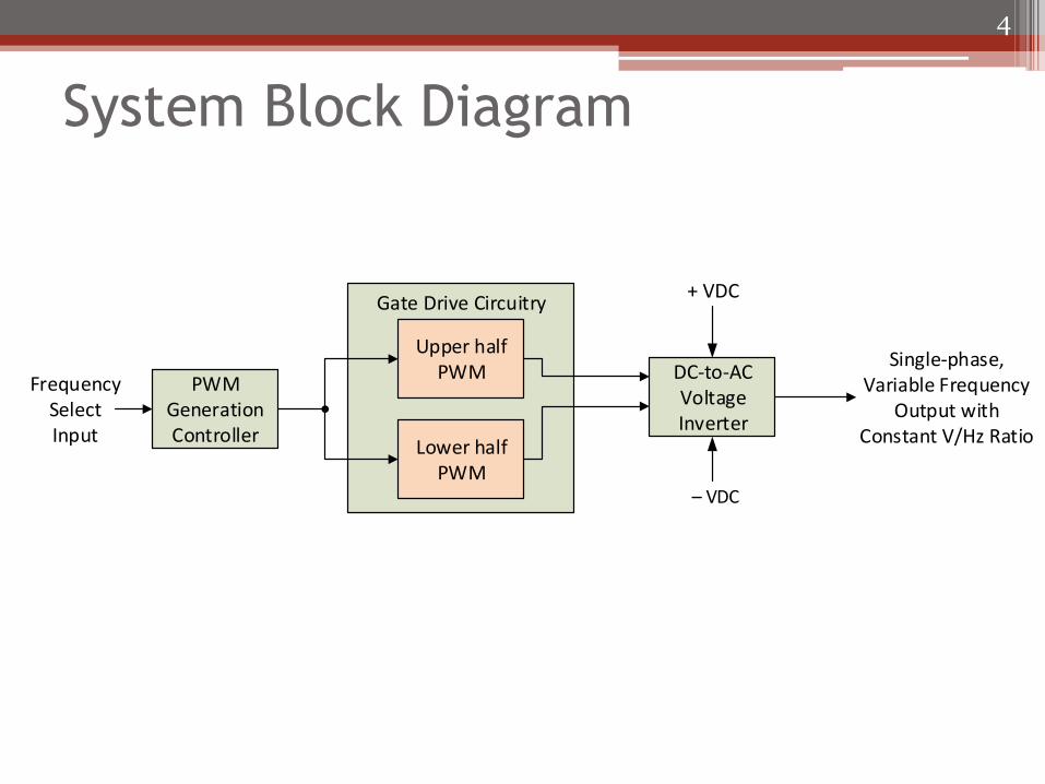
System Block Diagram
4
PWM Generation Controller
Gate Drive Circuitry
DC-to-AC Voltage Inverter
Upper half PWM
Lower half PWM
Frequency Select Input
+ VDC
– VDC
Single-phase, Variable Frequency
Output with Constant V/Hz Ratio

Eric Progress
• Work Accomplished
▫ Project Timeline
▫ Achievements
• Future Work
5

Subsystem Block Diagram
6
PWM Generation Controller
Gate Drive Circuitry
DC-to-AC Voltage Inverter
Upper half PWM
Lower half PWM
Frequency Select Input
+ VDC
– VDC
Single-phase, Variable Frequency
Output with Constant V/Hz Ratio

Work Accomplished
• Project Timeline
▫ Gantt Chart
• Achievements
7

Schedule
8
TASK WEEK
PERIODS 7 8 9 10 11 12 13 14 15 16 17 18 19 20 21 22
Proposal Presentation
Simulate PWM Controller
Code PWM Generation Controller
Progress Presentation
Plan % Complete Actual Beyond % Complete Beyond
27-Oct 3-Nov 10-Nov 17-Nov6-Oct 13-Oct 20-Oct29-Sep

PWM Subsystem Block Diagram
9
Triangle
Wave
Sine Wave
15kHz
Frequency 1 – 60Hz
Comparator Switched
PWM

MATLAB
10

MATLAB
• Problem Encountered
▫ An increase in sine frequency effects the sample
location in respect to time
• Solution
▫ Increase the frequency by changing how samples
are taken
11

MATLAB
• Equation for finding the samples needed at a
given frequency
• 𝑠𝑎𝑚𝑝𝑙𝑒_𝑟𝑎𝑡𝑒 = 𝑠𝑎𝑚𝑝𝑙𝑒𝑠/𝑓𝑟𝑒𝑞𝑢𝑒𝑛𝑐𝑦_𝑜𝑢𝑡▫ Samples = 150,000
▫ Sample_rate = varying values
12

MATLAB
13
Index time (sec) Triangle (15kHz)
Sine (1Hz) Sine (2Hz) Sine (60Hz)
0 0 0 0 0 0
1 0.0000067 0.2 4.19E-05 8.38E-05 0.002513271
2 0.0000737 0.4 8.38E-05 0.000167552 0.005026527
3 0.0001407 0.6 0.000125664 0.000251327 0.007539751
4 0.0002077 0.8 0.000167552 0.000335103 0.010052927
5 0.0002747 1 0.00020944 0.000418879 0.01256604
6 0.0003417 0.8 0.000251327 0.000502655 0.015079073
7 0.0004087 0.6 0.000293215 0.000586431 0.017592011
8 0.0004757 0.4 0.000335103 0.000670206 0.020104838
9 0.0005427 0.2 0.000376991 0.000753982 0.022617538
10 0.0006097 0 0.000418879 0.000837758 0.025130095

MATLAB
• Solution
▫ 𝑖𝑛𝑑𝑒𝑥 = 𝑖 ∗ 𝑓𝑠
▫ Where fs is the frequency 1 – 60Hz
▫ Where i is a count
▫ Where index is the location in the lookup table
14

MATLAB
15
Index time (sec) Triangle (15kHz)
Sine (1Hz) Sine (2Hz) Sine (60Hz)
0 0 0 0 0 0
1 0.0000067 0.2 4.19E-05 8.38E-05 0.002513271
2 0.0000737 0.4 8.38E-05 0.000167552 0.005026527
3 0.0001407 0.6 0.000125664 0.000251327 0.007539751
4 0.0002077 0.8 0.000167552 0.000335103 0.010052927
5 0.0002747 1 0.00020944 0.000418879 0.01256604
6 0.0003417 0.8 0.000251327 0.000502655 0.015079073
7 0.0004087 0.6 0.000293215 0.000586431 0.017592011
8 0.0004757 0.4 0.000335103 0.000670206 0.020104838
9 0.0005427 0.2 0.000376991 0.000753982 0.022617538
10 0.0006097 0 0.000418879 0.000837758 0.025130095

MATLAB
16
0
0.01
0.02
0.03
0.04
0.05
0.06
0.07
0.08
0.09
0 0.0005 0.001 0.0015 0.002
Am
plit
ud
e
Seconds
Sine Waves
Sine (1Hz) Sine (30Hz) Sine (60Hz)

MATLAB
17
0
0.1
0.2
0.3
0.4
0.5
0.6
0.7
0.8
0.9
1
0 0.0005 0.001 0.0015 0.002
Am
plit
ud
e
Seconds
Comparison Graph
Triangle Sine (1Hz) Sine (30Hz) Sine (60Hz)

Future Work
• Future Schedule
▫ Gantt Chart
• Atmel Studios
18

Future Schedule
19
TASK WEEK
PERIODS 21 22 23 24 25 26 39 40 41 42 43 44 45 46 47 48
Code PWM Generation Controller
Progress Presentation
Testing
Progress Presentation
Plan Actual Beyond
19-Jan 26-Jan 2-Feb 9-Feb 16-Feb17-Nov 24-Nov 1-Dec

Atmel Studios
• Lookup Tables
• LCD
• Keypad
20

Leslie’s Progress
• Schedule
• Progress on gate drive circuitry and DC-to-AC
voltage inverter
• Plan of action for future work
21

October 1 – November 19
22
Plan % Complete
TASK WEEK 1-Oct 6-Oct 13-Oct 20-Oct 27-Oct 3-Nov 10-Nov 17-Nov 19-Nov
PERIODS 7 8 9 10 11 12 13 14 15 16 17 18 19 20 21 22 23 24
Proposal Presentation
Design Gate Driver
Initial Testing of Gate Driver
Design Inverter
Initial Testing of Inverter
Progress Presentation

Design of Gate Drive Circuitry
• Two 8-pin Avago HCPL-3120 chips
▫ 18 V supply
▫ High and low side drivers
23
High Side Driver
Low Side Driver
+VDC
- VDC
Single-phase Output
Gate Drive Circuitry
Upper Half PWM
Lower Half PWM

Initial Testing of Gate Drive
Circuitry
24
1 HCPL-3120 8
2 7
3 6
4 5Open
Collector
5 V
RPullup
TTL
18 V
Vo

Results of Initial Testing of Gate
Drive Circuitry
25
Output
Input

Design of Gate Drive Circuitry and
DC-to-AC Voltage Inverter
26
1 HCPL-3120 8
2 7
3 6
4 5Open
Collector
5 V
RPullup
Rg
Switched PWM
18 V
18 V
RLoad
IRF640

November 19 – February 16
27
Plan % Complete
TASK WEEK 19-Nov 24-Nov 1-Dec 19-Jan 26-Jan 2-Feb 9-Feb 16-Feb
PERIODS 21 22 23 24 25 26 39 40 41 42 43 44 45 46 47 48
Design Inverter
Initial Testing of Inverter
Testing
Progress Presentation

Conclusion
• Future work
• Eric working on PWM
• Leslie working on the further testing
▫ Gate drive
▫ Inverter
28

Single-phase Variable Frequency
Switch Gear
Department of Electrical and
Computer Engineering
Eric Motyl and Leslie Zeman
Advisor: Professor Steven D. Gutschlag
November 19, 2015
29

Bootstrap Capacitor Arrangement
for High Side Driver
1 HCPL-3120 8
2 7
3 6
4 5Open
Collector
Switched PWM
5 V
RPullup
Rg
18-20 V
VEE
CBS
To DC-to-AC Voltage Inverter
Single-Phase Output
30

Gate Drive Circuitry
31