Single-Phase, Integrated Heatsink Type SSR SRH1 Series ...
12
I-15 (A) Photoelectric Sensors (B) Fiber Optic Sensors (C) Door/Area Sensors (D) Proximity Sensors (E) Pressure Sensors (F) Rotary Encoders (G) Connectors/ Connector Cables/ Sensor Distribution Boxes/Sockets (H) Temperature Controllers (I) SSRs / Power Controllers (J) Counters (K) Timers (L) Panel Meters (M) Tacho / Speed / Pulse Meters (N) Display Units (O) Sensor Controllers (P) Switching Mode Power Supplies (Q) Stepper Motors & Drivers & Controllers (R) Graphic/ Logic Panels (S) Field Network Devices (T) Software Features Single-Phase, Integrated Heatsink Type SSR [Top-Bottom Terminal] Ordering Information Please read “Safety considerations” in operation manual before using. [Voltage input type] [Current input type] ● High heat dissipation efficiency with ceramic PCB and integrated heatsink ● Input Indicator (green LED) ● DIN rail mount or panel mount installation [Voltage input type] Zero cross turn-on, random turn-on models available [Current input type] Phase control and cycle control possible - Phase control (power equality division/phase equality division) - Cycle control (fixed cycle/variable cycle) 20A/30A 60A 10A/15A/20A 60A 30A/40A Rated load current Rated load current Rated input Control phase Item Rated load current (resistive load) Function Version 1 1 2 15 - - Voltage input type Current input type N Renewal No Mark Zero cross turn-on - R Random turn-on - 10 10A - 15 15A - 20 20A 20A 30 30A 30A 40 40A - 60 60A 60A 2 24-240VAC 100-240VAC 4 48-480VAC 200-480VAC 1 4-30VDC - 2 24VAC - 4 90-240VAC - A - 4-20mA 1 Single-phase No Mark Top-Bottom terminal SRH Solid State Relay (integrated heatsink type) Rated load voltage N ※This ordering informaion is only for reference. For ordering a specific model, check the ordering information of the model. ※For more information about models, refer to the B-16 page for the voltage input type B-22 page for the current input type Single-Phase, Integrated Heatsink Type SSR [Top-Bottom Terminal] SRH1 Series SRH Input/output terminal
Transcript of Single-Phase, Integrated Heatsink Type SSR SRH1 Series ...
I-15
(A) Photoelectric Sensors
(B) FiberOpticSensors
(C) Door/AreaSensors
(D) ProximitySensors
(E) PressureSensors
(F) RotaryEncoders
(G)Connectors/Connector Cables/Sensor Distribution Boxes/Sockets
(H)TemperatureControllers
(I)SSRs / PowerControllers
(J) Counters
(K) Timers
(L) PanelMeters
(M)Tacho /Speed / PulseMeters
(N)DisplayUnits
(O)SensorControllers
(P)SwitchingMode PowerSupplies
(Q)Stepper Motors & Drivers & Controllers
(R)Graphic/LogicPanels
(S)FieldNetworkDevices
(T) Software
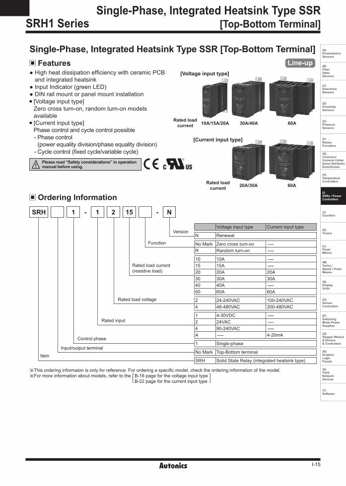
FeaturesSingle-Phase, Integrated Heatsink Type SSR [Top-Bottom Terminal]
Ordering Information
Please read “Safety considerations” in operation manual before using.
[Voltage input type]
[Current input type]
High heat dissipation efficiency with ceramic PCB and integrated heatsink
Input Indicator (green LED) DIN rail mount or panel mount installation [Voltage input type] Zero cross turn-on, random turn-on models available [Current input type] Phase control and cycle control possible- Phase control
(power equality division/phase equality division)- Cycle control (fixed cycle/variable cycle)
20A/30A 60A
10A/15A/20A 60A30A/40ARated load current
Rated load current
Rated input
Control phase
Item
Rated load current(resistive load)
Function
Version
11 2 15- -
Voltage input type Current input type
N Renewal
No Mark Zero cross turn-on -R Random turn-on -
10 10A -15 15A -20 20A 20A30 30A 30A40 40A -60 60A 60A
2 24-240VAC 100-240VAC4 48-480VAC 200-480VAC
1 4-30VDC -2 24VAC -4 90-240VAC -A - 4-20mA
1 Single-phase
No Mark Top-Bottom terminal
SRH Solid State Relay (integrated heatsink type)
Rated load voltage
N
※This ordering informaion is only for reference. For ordering a specific model, check the ordering information of the model.※For more information about models, refer to the B-16 page for the voltage input type
B-22 page for the current input type
Single-Phase, Integrated Heatsink Type SSR[Top-Bottom Terminal]SRH1 Series
SRH
Input/output terminal

I-16
SRH1 Series
Specifications Input
Rated input voltage range 4-30VDCᜡ 24VACrmsᜠ (50/60Hz) 90-240VACrmsᜠ (50/60Hz) Allowable input voltage range 4-32VDCᜡ 19-30VACrmsᜠ (50/60Hz) 85-264VACrmsᜠ (50/60Hz)Max. input current 18mA 15mArms (24VACrmsᜠ) 18mArms (240VACrmsᜠ)Pick-up voltage Min. 4VDCᜡ Min. 19VACrmsᜠ Min. 85VACrmsᜠDrop-out voltage Max. 1VDCᜡ Max. 4VACrmsᜠ Max. 10VACrmsᜠTurn-on time
Zero cross turn-on Max. 0.5 cycle of load source + 1ms Max. 2 cycle of load source + 1ms Max. 2 cycle of load source + 1msRandom turn-on Max. 1ms - -
Turn-off time Max. 0.5 cycle of load source + 1ms Max. 2 cycle of load source + 1ms Max. 2 cycle of load source + 1ms
Model Rated input voltage Rated load voltage Rated input current FunctionSRH1-1210-N 4-30VDC
10A
24-240VAC Zero cross turn-on
SRH1-2210-N 24VACSRH1-4210-N 90-240VACSRH1-1215-N 4-30VDC
15ASRH1-2215-N 24VACSRH1-4215-N 90-240VACSRH1-1220-N 4-30VDC
20ASRH1-2220-N 24VACSRH1-4220-N 90-240VACSRH1-1230-N 4-30VDC
30ASRH1-2230-N 24VACSRH1-4230-N 90-240VACSRH1-1240-N 4-30VDC
40ASRH1-2240-N 24VACSRH1-4240-N 90-240VACSRH1-1260-N 4-30VDC
60ASRH1-2260-N 24VACSRH1-4260-N 90-240VACSRH1-1410-N
4-30VDC10A
48-480VAC
Zero cross turn-onSRH1-1410R-N Random turn-onSRH1-2410-N 24VAC Zero cross turn-onSRH1-1415-N
4-30VDC15A
Zero cross turn-onSRH1-1415R-N Random turn-onSRH1-2415-N 24VAC Zero cross turn-onSRH1-1420-N
4-30VDC20A
Zero cross turn-onSRH1-1420R-N Random turn-onSRH1-2420-N 24VAC Zero cross turn-onSRH1-1430-N
4-30VDC30A
Zero cross turn-onSRH1-1430R-N Random turn-onSRH1-2430-N 24VAC Zero cross turn-onSRH1-1440-N
4-30VDC40A
Zero cross turn-onSRH1-1440R-N Random turn-onSRH1-2440-N 24VAC Zero cross turn-onSRH1-1460-N
4-30VDC60A
Zero cross turn-onSRH1-1460R-N Random turn-onSRH1-2460-N 24VAC Zero cross turn-on
Single-Phase, Integrated Heatsink Type SSR [Voltage Input Type] Model

I-17
(A) Photoelectric Sensors
(B) FiberOpticSensors
(C) Door/AreaSensors
(D) ProximitySensors
(E) PressureSensors
(F) RotaryEncoders
(G)Connectors/Connector Cables/Sensor Distribution Boxes/Sockets
(H)TemperatureControllers
(I)SSRs / PowerControllers
(J) Counters
(K) Timers
(L) PanelMeters
(M)Tacho /Speed / PulseMeters
(N)DisplayUnits
(O)SensorControllers
(P)SwitchingMode PowerSupplies
(Q)Stepper Motors & Drivers & Controllers
(R)Graphic/LogicPanels
(S)FieldNetworkDevices
(T) Software
OutputRated load voltage range 24-240VACrmsᜠ (50/60Hz)Allowable load voltage range 24-264VACrmsᜠ (50/60Hz)Rated load current
Resistive load (AC-51)※1 10Arms 15Arms 20Arms 30Arms 40Arms 60Arms
Min. load current 0.15Arms 0.15Arms 0.2Arms 0.5Arms 0.5Arms 0.5ArmsMax. 1 cycle surge current (60Hz) 160A 160A 250A 400A 500A 1000A
Max. non-repetitive surge current (I2t, t=8.3ms) 130A2s 130A2s 300A2s 910A2s 1000A2s 4000A2s
Peak voltage (non-repetitive) 600VLeakage current (Ta=25) Max. 10mArms (240VACᜠ/60Hz)Output on voltage drop [Vpk] (max. load current) Max. 1.6V
Static off state dv/dt 500V/Rated load voltage range 48-480VACrmsᜠ (50/60Hz)Allowable load voltage range 48-528VACrmsᜠ (50/60Hz) Rated load current
Resistive load (AC-51)※1 10Arms 15Arms 20Arms 30Arms 40Arms 60Arms
Min. load current 0.5Arms 0.5Arms 0.5Arms 0.5Arms 0.5Arms 0.5ArmsMax. 1 cycle surge current (60Hz) 300A 300A 300A 500A 500A 1000A
Max. non-repetitive surge current (I2t, t=8.3ms) 350A2s 350A2s 350A2s 1000A2s 1000A2s 4000A2s
Peak voltage (non-repetitive) 1200V (zero cross turn-on), 1000V (random turn-on)Leakage current (Ta=25) Max. 10mArms (480VACᜠ/60Hz)Output on voltage drop [Vpk] (max. load current) Max. 1.6V
Static off state dv/dt 500V/※1: AC-51 is utilization category at IEC60947-4-3.
General specifications
※1: The weight includes packaging. The weight in parenthesis is for unit only.※Environment resistance is rated at no freezing or condensation. ※For wiring the terminal, round terminal must be used.
Dielectric strength (Vrms) 2500VAC 50/60Hz 1 min (input-output, input/output-case)Insulation resistance Over 100MΩ (at 500VDC megger) (input-output, input/output-case)Indicator Input indicator: green LED
VibrationMechanical 0.75mm amplitude at frequency of 10 to 55Hz (for 1 min) in each X, Y, Z direction for 1 hourMalfunction 0.5mm amplitude at frequency of 10 to 55Hz (for 1 min) in each X, Y, Z direction for 10 min
ShockMechanical 300m/s² (approx. 30G) in each X, Y, Z direction for 3 timesMalfunction 100m/s² (approx. 30G) in each X, Y, Z direction for 3 times
EnvironmentAmbient temp. -30 to 80 (in case of the rated input voltage 90-240VACᜠ: -20 to 70), storage: -30 to 100
( The rated load current capacity is different depending on ambient temperature. Refer to ' SSR Derating Curve'.)Ambient humi. 45 to 85%RH, storage: 45 to 85%RH
Input terminal connection Min. 1×0.5mm2 (1×AWG20), max. 1×1.5mm2 (1×AWG16) or 2×1.5mm2 (2×AWG16)
Output terminal connection
Rated load current 10A/15A/20A : Min. 1×0.75mm2 (1×AWG18), max. 1×4mm2 (1×AWG12) or 2×2.5mm2 (2×AWG14) Rated load current 30A/40A/60A : Min. 1×1.5mm2 (1×AWG16), max. 1×16mm2 (1×AWG6) or 2×6mm2 (2×AWG10)
※Use wires compliant with load current capacity to connect to the terminal.Input terminal fixed torque 0.75 to 0.95N.m
Output terminal fixed torque Rated load current 10A/15A/20A: 1.0 to 1.35N·m Rated load current 30A/40A/60A: 1.6 to 2.2N·m
Approval ᜢ ᜧ
Weight※1 Rated load current 10A/15A/20A: approx. 298g (approx. 225g) Rated load current 30A/40A: approx. 500g (approx. 410g) Rated load current 60A: approx. 770g (approx. 680g)
Single-Phase, Integrated Heatsink Type SSR[Voltage Input Type]
I-18
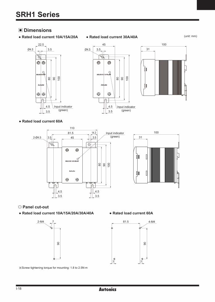
SRH1 Series
Dimensions (unit: mm)
Rated load current 60A
Rated load current 10A/15A/20A Rated load current 30A/40A
Panel cut-out
※Screw tightening torque for mounting: 1.8 to 2.5N.m
Rated load current 10A/15A/20A/30A/40A Rated load current 60A
31
100
2-Ø4.514.33.53.5
4.53.5 3.5
4.5
110
4581.5
80 90 100
Input indicator(green)
3.5Ø4.5
3.5
22.5
100
9080
Input indicator(green)
4.5
3.5Ø4.5
3.5
45
100
9080
Input indicator(green)
31100
4.5
2-M4
90
7 81.5
90
4-M4
77
I-19
(A) Photoelectric Sensors
(B) FiberOpticSensors
(C) Door/AreaSensors
(D) ProximitySensors
(E) PressureSensors
(F) RotaryEncoders
(G)Connectors/Connector Cables/Sensor Distribution Boxes/Sockets
(H)TemperatureControllers
(I)SSRs / PowerControllers
(J) Counters
(K) Timers
(L) PanelMeters
(M)Tacho /Speed / PulseMeters
(N)DisplayUnits
(O)SensorControllers
(P)SwitchingMode PowerSupplies
(Q)Stepper Motors & Drivers & Controllers
(R)Graphic/LogicPanels
(S)FieldNetworkDevices
(T) Software
Single-Phase, Integrated Heatsink Type SSR[Voltage Input Type]
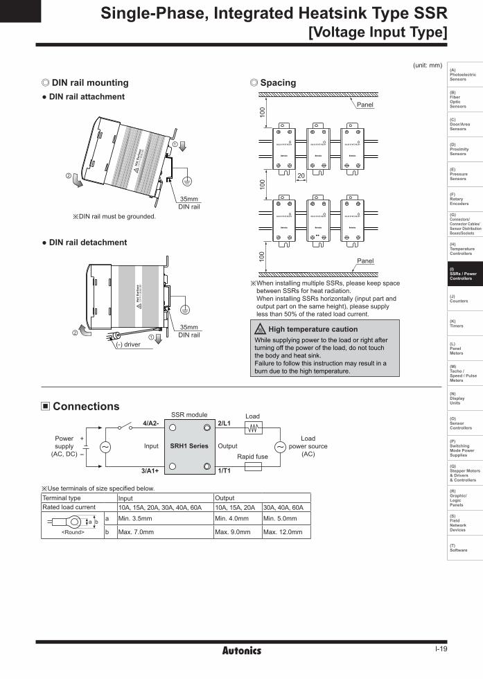
DIN rail mounting Spacing
(unit: mm)
DIN rail attachment
DIN rail detachment
※DIN rail must be grounded.
②
35mm DIN rail
①
35mm DIN rail
(-) driver
② ①
Connections
+
-
SSR module
Rapid fuse
Load
SRH1 SeriesLoad
power source(AC)
Power supply
(AC, DC)Input Output
1/T13/A1+
4/A2- 2/L1
※ When installing multiple SSRs, please keep space between SSRs for heat radiation. When installing SSRs horizontally (input part and output part on the same height), please supply less than 50% of the rated load current.
While supplying power to the load or right after turning off the power of the load, do not touch the body and heat sink.Failure to follow this instruction may result in a burn due to the high temperature.
High temperature caution
※Use terminals of size specified below.Terminal type Input OutputRated load current 10A, 15A, 20A, 30A, 40A, 60A 10A, 15A, 20A 30A, 40A, 60A
a b
<Round>
a Min. 3.5mm Min. 4.0mm Min. 5.0mm
b Max. 7.0mm Max. 9.0mm Max. 12.0mm
100
Panel
20
Panel10
010
0
I-20
SRH1 Series
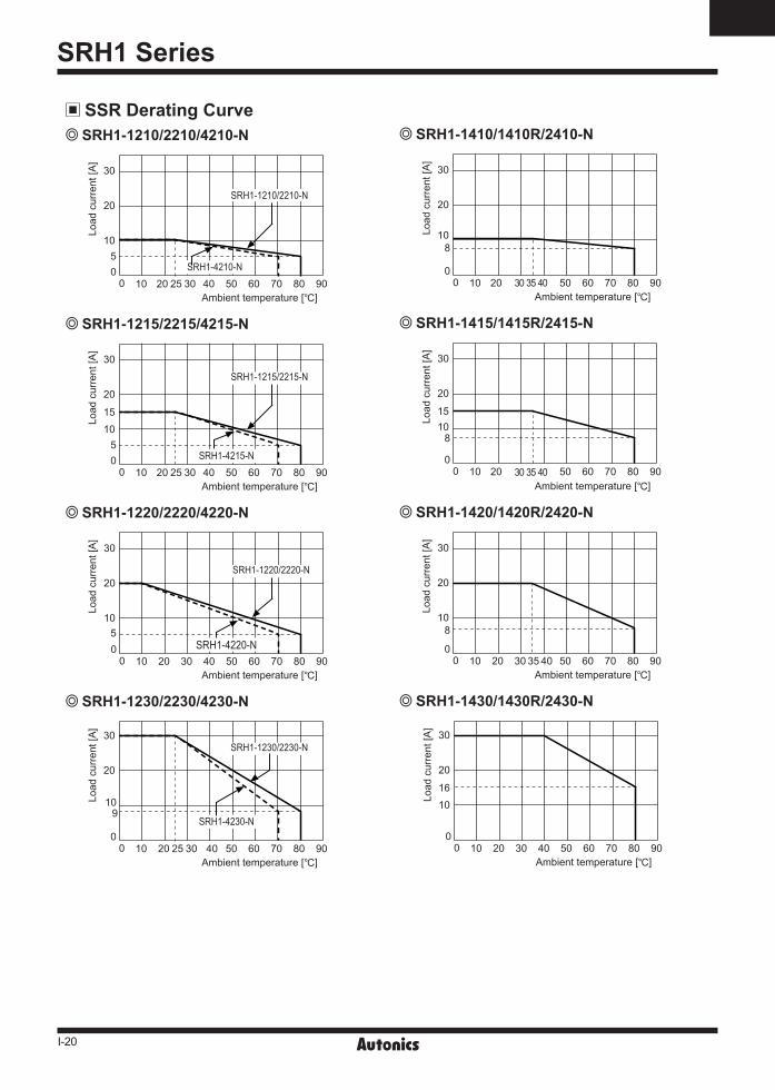
SSR Derating Curve
SRH1-1420/1420R/2420-N
SRH1-1430/1430R/2430-N
SRH1-1215/2215/4215-N
SRH1-1220/2220/4220-N
SRH1-1230/2230/4230-N
SRH1-1410/1410R/2410-N SRH1-1210/2210/4210-N
SRH1-1415/1415R/2415-N
10 20 3530 40 50 60 70 80 900
0
30
20
108
Ambient temperature []
Load
cur
rent
[A]
SRH1-4210-N10 20 25 30 40 50 60 70 80 90
00
30
20
105
SRH1-1210/2210-N
Ambient temperature []
Load
cur
rent
[A]
Ambient temperature []10 20 50 60 70 80 90
00
30
20
1015
8
3530 40
Load
cur
rent
[A]
10 20 30 40 50 60 70 80 900
0
30
20
108
35Ambient temperature []
Load
cur
rent
[A]
10 20 30 40 50 60 70 80 900
0
30
20
1016
Ambient temperature []
Load
cur
rent
[A]
10 20 25 30 40 50 60 70 80 900
0
30
20
1015
5
SRH1-1215/2215-N
SRH1-4215-N
Ambient temperature []
Load
cur
rent
[A]
10 20 30 40 50 60 70 80 900
0
30
20
10
SRH1-1220/2220-N
5SRH1-4220-N
Load
cur
rent
[A]
Ambient temperature []
2520 30
SRH1-1230/2230-N
SRH1-4230-N
10 40 50 60 70 80 900
0
30
20
109
Load
cur
rent
[A]
Ambient temperature []
I-21
(A) Photoelectric Sensors
(B) FiberOpticSensors
(C) Door/AreaSensors
(D) ProximitySensors
(E) PressureSensors
(F) RotaryEncoders
(G)Connectors/Connector Cables/Sensor Distribution Boxes/Sockets
(H)TemperatureControllers
(I)SSRs / PowerControllers
(J) Counters
(K) Timers
(L) PanelMeters
(M)Tacho /Speed / PulseMeters
(N)DisplayUnits
(O)SensorControllers
(P)SwitchingMode PowerSupplies
(Q)Stepper Motors & Drivers & Controllers
(R)Graphic/LogicPanels
(S)FieldNetworkDevices
(T) Software
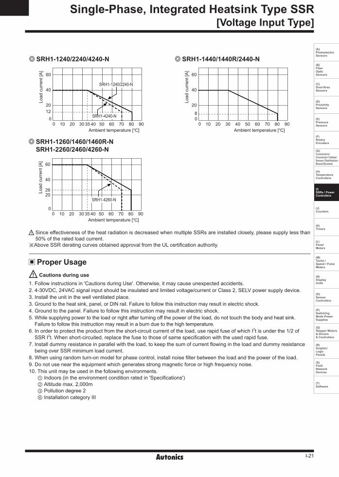
Since effectiveness of the heat radiation is decreased when multiple SSRs are installed closely, please supply less than 50% of the rated load current.
※ Above SSR derating curves obtained approval from the UL certification authority.
Proper UsageCautions during use
1. Follow instructions in 'Cautions during Use'. Otherwise, it may cause unexpected accidents.2. 4-30VDC, 24VAC signal input should be insulated and limited voltage/current or Class 2, SELV power supply device.3. Install the unit in the well ventilated place. 3. Ground to the heat sink, panel, or DIN rail. Failure to follow this instruction may result in electric shock.4. Ground to the panel. Failure to follow this instruction may result in electric shock.5. While supplying power to the load or right after turning off the power of the load, do not touch the body and heat sink.
Failure to follow this instruction may result in a burn due to the high temperature.6. In order to protect the product from the short-circuit current of the load, use rapid fuse of which I2t is under the 1/2 of
SSR I2t. When short-circuited, replace the fuse to those of same specification with the used rapid fuse.7. Install dummy resistance in parallel with the load, to keep the sum of current flowing in the load and dummy resistance
being over SSR minimum load current.8. When using random turn-on model for phase control, install noise filter between the load and the power of the load.9. Do not use near the equipment which generates strong magnetic force or high frequency noise.10. This unit may be used in the following environments.
① Indoors (in the environment condition rated in 'Specifications') ② Altitude max. 2,000m ③ Pollution degree 2 ④ Installation category III
10 20 30 40 50 60 70 80 900
0
60
40
2026
35
SRH1-4260-N
Load
cur
rent
[A]
Ambient temperature []
SRH1-1260/1460/1460R-N SRH1-2260/2460/4260-N
SRH1-1440/1440R/2440-N SRH1-1240/2240/4240-N
10 20 30 40 50 60 70 80 900
0
60
40
20
8
Ambient temperature []
Load
cur
rent
[A]
SRH1-1240/2240-N
SRH1-4240-N
10 20 30 40 50 60 70 80 900
0
60
40
2012
35
Load
cur
rent
[A]
Ambient temperature []
Single-Phase, Integrated Heatsink Type SSR[Voltage Input Type]
I-22
SRH1 Series
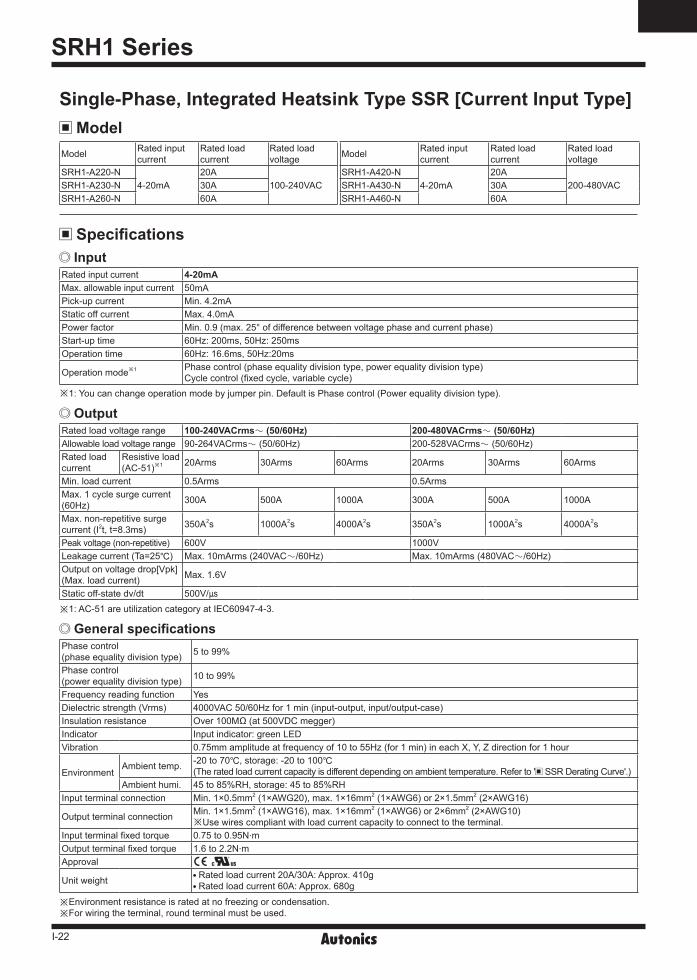
InputRated input current 4-20mAMax. allowable input current 50mAPick-up current Min. 4.2mAStatic off current Max. 4.0mAPower factor Min. 0.9 (max. 25° of difference between voltage phase and current phase)Start-up time 60Hz: 200ms, 50Hz: 250msOperation time 60Hz: 16.6ms, 50Hz:20ms
Operation mode※1 Phase control (phase equality division type, power equality division type)Cycle control (fixed cycle, variable cycle)
※1: You can change operation mode by jumper pin. Default is Phase control (Power equality division type).
Specifications
General specificationsPhase control(phase equality division type) 5 to 99%
Phase control(power equality division type) 10 to 99%
Frequency reading function YesDielectric strength (Vrms) 4000VAC 50/60Hz for 1 min (input-output, input/output-case)Insulation resistance Over 100MΩ (at 500VDC megger)Indicator Input indicator: green LEDVibration 0.75mm amplitude at frequency of 10 to 55Hz (for 1 min) in each X, Y, Z direction for 1 hour
EnvironmentAmbient temp. -20 to 70, storage: -20 to 100
(The rated load current capacity is different depending on ambient temperature. Refer to ' SSR Derating Curve'.)Ambient humi. 45 to 85%RH, storage: 45 to 85%RH
Input terminal connection Min. 1×0.5mm2 (1×AWG20), max. 1×16mm2 (1×AWG6) or 2×1.5mm2 (2×AWG16)
Output terminal connection Min. 1×1.5mm2 (1×AWG16), max. 1×16mm2 (1×AWG6) or 2×6mm2 (2×AWG10)※Use wires compliant with load current capacity to connect to the terminal.
Input terminal fixed torque 0.75 to 0.95N.mOutput terminal fixed torque 1.6 to 2.2N.mApproval ᜢ ᜧ
Unit weight Rated load current 20A/30A: Approx. 410g Rated load current 60A: Approx. 680g
※Environment resistance is rated at no freezing or condensation.※For wiring the terminal, round terminal must be used.
OutputRated load voltage range 100-240VACrmsᜠ (50/60Hz) 200-480VACrmsᜠ (50/60Hz)Allowable load voltage range 90-264VACrmsᜠ (50/60Hz) 200-528VACrmsᜠ (50/60Hz)Rated loadcurrent
Resistive load(AC-51)※1 20Arms 30Arms 60Arms 20Arms 30Arms 60Arms
Min. load current 0.5Arms 0.5ArmsMax. 1 cycle surge current (60Hz) 300A 500A 1000A 300A 500A 1000A
Max. non-repetitive surge current (I2t, t=8.3ms) 350A2s 1000A2s 4000A2s 350A2s 1000A2s 4000A2s
Peak voltage (non-repetitive) 600V 1000VLeakage current (Ta=25) Max. 10mArms (240VACᜠ/60Hz) Max. 10mArms (480VACᜠ/60Hz)Output on voltage drop[Vpk] (Max. load current) Max. 1.6V
Static off-state dv/dt 500V/※1: AC-51 are utilization category at IEC60947-4-3.
Model Rated input current
Rated load current
Rated load voltage
SRH1-A220-N 4-20mA
20A 100-240VAC SRH1-A230-N 30A
SRH1-A260-N 60A
Model Rated input current
Rated load current
Rated load voltage
SRH1-A420-N 4-20mA
20A 200-480VAC SRH1-A430-N 30A
SRH1-A460-N 60A
Single-Phase, Integrated Heatsink Type SSR [Current Input Type] Model
I-23
(A) Photoelectric Sensors
(B) FiberOpticSensors
(C) Door/AreaSensors
(D) ProximitySensors
(E) PressureSensors
(F) RotaryEncoders
(G)Connectors/Connector Cables/Sensor Distribution Boxes/Sockets
(H)TemperatureControllers
(I)SSRs / PowerControllers
(J) Counters
(K) Timers
(L) PanelMeters
(M)Tacho /Speed / PulseMeters
(N)DisplayUnits
(O)SensorControllers
(P)SwitchingMode PowerSupplies
(Q)Stepper Motors & Drivers & Controllers
(R)Graphic/LogicPanels
(S)FieldNetworkDevices
(T) Software
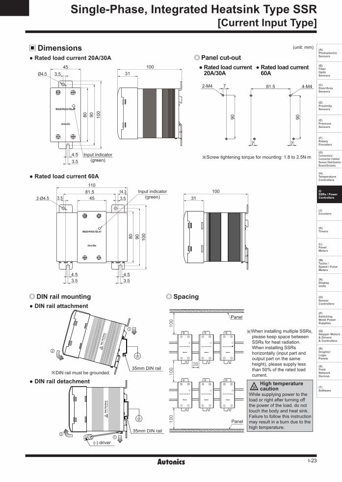
Dimensions (unit: mm)
Rated load current 20A/30A
Rated load current 60A
Rated load current 20A/30A
Rated load current 60A
※When installing multiple SSRs, please keep space between SSRs for heat radiation. When installing SSRs horizontally (input part and output part on the same height), please supply less than 50% of the rated load current.
While supplying power to the load or right after turning off the power of the load, do not touch the body and heat sink.Failure to follow this instruction may result in a burn due to the high temperature.
High temperaturecaution
DIN rail mounting Spacing DIN rail attachment
DIN rail detachment
※Screw tightening torque for mounting: 1.8 to 2.5N.m
※DIN rail must be grounded.
35mm DIN rail
35mm DIN rail
(-) driver
Panel cut-out
Panel
Panel
②
②
①
①
Single-Phase, Integrated Heatsink Type SSR[Current Input Type]
100
100
100
20
3.5Ø4.5
3.5
45
100
9080
Input indicator(green)
31100
4.5
31100
2-Ø4.514.33.53.5
4.53.5 3.5
4.5
110
4581.5
80 90 100
Input indicator(green)
2-M4
90
7 81.5
90
4-M4
77
I-24
SRH1 Series
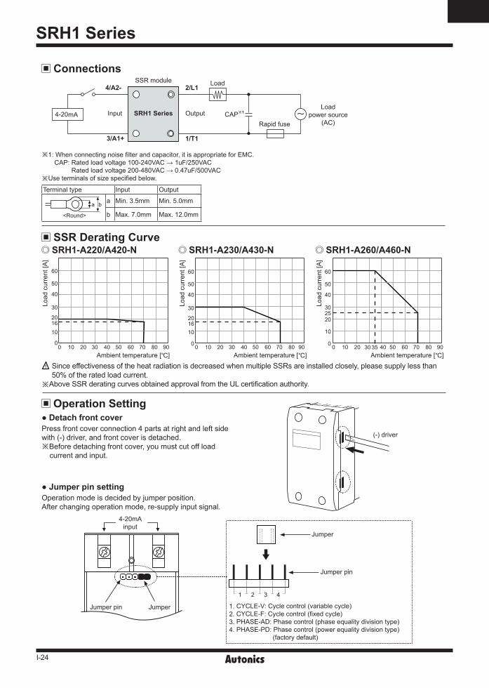
ConnectionsSSR module
Rapid fuse
Load
SRH1 SeriesLoad
power source(AC)
4-20mA
4-20mAinput
CAP※1Input Output
(-) driver
Jumper
Jumper
Jumper pin
1. CYCLE-V: Cycle control (variable cycle)2. CYCLE-F: Cycle control (fixed cycle)3. PHASE-AD: Phase control (phase equality division type)4. PHASE-PD: Phase control (power equality division type) (factory default)
1 2 3 4
Jumper pin
2/L14/A2-
3/A1+ 1/T1
SSR Derating Curve
Operation Setting Detach front cover
Jumper pin setting
Press front cover connection 4 parts at right and left side with (-) driver, and front cover is detached.※Before detaching front cover, you must cut off load
current and input.
Operation mode is decided by jumper position.After changing operation mode, re-supply input signal.
※1: When connecting noise filter and capacitor, it is appropriate for EMC. CAP: Rated load voltage 100-240VAC → 1uF/250VAC
Rated load voltage 200-480VAC → 0.47uF/500VAC※Use terminals of size specified below.
SRH1-A220/A420-N
Load
cur
rent
[A]
Ambient temperature []0
40
30
60
50
201610
010 20 30 40 50 60 70 80 90
SRH1-A260/A460-N
Load
cur
rent
[A]
Ambient temperature []0
40
30
60
50
2025
10
0 10 20 30 40 50 60 70 80 9035
SRH1-A230/A430-N
Load
cur
rent
[A]
Ambient temperature []0
40
30
60
50
201610
0 10 20 30 40 50 60 70 80 90
Since effectiveness of the heat radiation is decreased when multiple SSRs are installed closely, please supply less than 50% of the rated load current.
※ Above SSR derating curves obtained approval from the UL certification authority.
Terminal type Input Output
a b
<Round>
a Min. 3.5mm Min. 5.0mm
b Max. 7.0mm Max. 12.0mm
I-25
(A) Photoelectric Sensors
(B) FiberOpticSensors
(C) Door/AreaSensors
(D) ProximitySensors
(E) PressureSensors
(F) RotaryEncoders
(G)Connectors/Connector Cables/Sensor Distribution Boxes/Sockets
(H)TemperatureControllers
(I)SSRs / PowerControllers
(J) Counters
(K) Timers
(L) PanelMeters
(M)Tacho /Speed / PulseMeters
(N)DisplayUnits
(O)SensorControllers
(P)SwitchingMode PowerSupplies
(Q)Stepper Motors & Drivers & Controllers
(R)Graphic/LogicPanels
(S)FieldNetworkDevices
(T) Software
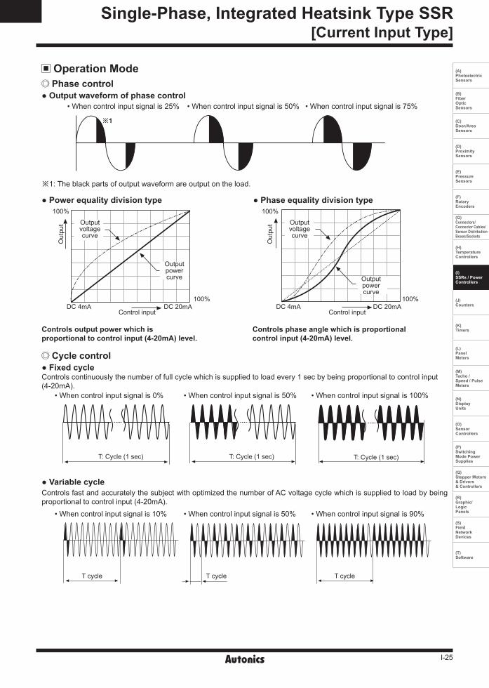
Phase control
Cycle control
Output waveform of phase control
Controls output power which isproportional to control input (4-20mA) level.
Controls phase angle which is proportionalcontrol input (4-20mA) level.
Fixed cycle
Variable cycle
Power equality division type Phase equality division type
Operation Mode
• When control input signal is 25%
• When control input signal is 0%
• When control input signal is 10%
Controls fast and accurately the subject with optimized the number of AC voltage cycle which is supplied to load by being proportional to control input (4-20mA).
Controls continuously the number of full cycle which is supplied to load every 1 sec by being proportional to control input (4-20mA).
• When control input signal is 50%
• When control input signal is 50%
• When control input signal is 50%
• When control input signal is 75%
• When control input signal is 100%
• When control input signal is 90%
※1: The black parts of output waveform are output on the load.
※1
T cycle
T: Cycle (1 sec) T: Cycle (1 sec)
Control inputDC 20mA
Outputpowercurve
Outputvoltagecurve
Out
put
DC 4mA
100%
100%
Outputpowercurve
Outputvoltagecurve
Out
put
DC 4mA
100%
100%DC 20mA
Control input
T: Cycle (1 sec)
T cycle T cycle
Single-Phase, Integrated Heatsink Type SSR[Current Input Type]
I-26
SRH1 Series
Proper UsageCautions during use
1. Follow instructions in 'Cautions during Use'. Otherwise, it may cause unexpected accidents.2. Install the unit in the well ventilated place.3. Ground to the heat sink, panel, or DIN rail. Failure to follow this instruction may result in electric shock.4. While supplying power to the load or right after turning off the power of the load, do not touch the body and heat sink.
Failure to follow this instruction may result in a burn due to the high temperature.5. In order to protect the product from the short-circuit current of the load, use rapid fuse of which I2t is under the 1/2 of
SSR I2t. When short-circuited, replace the fuse to those of same specification with the used rapid fuse.6. Install dummy resistance in parallel with the load, to keep the sum of current flowing in the load and dummy resistance
being over SSR minimum load current.7. Do not use near the equipment which generates strong magnetic force or high frequency noise.8. This unit may be used in the following environments.
① Indoors (in the environment condition rated in 'Specifications') ② Altitude max. 2,000m ③ Pollution degree 2 ④ Installation category III