Simulation Studies on the Coupling Process of …cdn.intechweb.org/pdfs/13549.pdf · Introduction...
23
24 Simulation Studies on the Coupling Process of Heat/Mass Transfer in a Metal Hydride Reactor Fusheng Yang and Zaoxiao Zhang Xi’an Jiaotong University P.R.China 1. Introduction Many substances can react with hydrogen under certain conditions, and the products are generally called hydrides. The binary hydrides can be classified into ionic hydrides, covalent hydrides and stable complex hydrides (Berube et al., 2007). The metal hydrides (MH), which feature metallic bonding between hydrogen and host material, belong to the second category and are investigated here. Since the successful development of LaNi 5 and TiFe as hydrogen storage materials in 1970s, studies on the metal hydrides have attracted many attentions. According to (Sandrock & Bowman, 2003), two properties among all have been found crucial in MH applications: 1. The easily reversed gas-solid chemical reaction, which is expressed as follows, 2 2 x x M H MH H + ↔ +Δ (1) Here M denotes a certain kind of metal or alloy, while MH x is the metal hydride as product. ΔH, the enthalpy change during hydriding/ dehydriding reaction, is generally 30~40kJ/ mol H 2 . 2. The well known Van’t Hoff equation relating plateau pressure to temperature. g g ln e H S P RT R Δ Δ = − (2) For the hydriding/dehydriding reaction, there exists a phase during which the stored amount of H 2 varies a lot while the equilibrium pressure almost keeps constant, the phase is generally called “plateau”. The equilibrium pressure in this phase, as shown in Equation (2), depends on the temperature. ΔH and ΔS are the enthalpy and entropy changes during hydriding/dehydriding reaction, respectively. Both parameters take quite different values for various MH materials, thus a wide range of operation temperature and pressure can be covered. Because of the unique properties mentioned above, MHs can be applied for a number of uses, e.g. hydrogen storage (Kaplan et al., 2006), heat storage (Felderhoff & Bogdanovic, 2009), thermal compression (Murthukumar et al., 2005; Kim et al., 2008; Wang et al., 2010), heat pump (Qin et al., 2008; Paya et al., 2009; Meng et al., 2010), gas separation and www.intechopen.com
Transcript of Simulation Studies on the Coupling Process of …cdn.intechweb.org/pdfs/13549.pdf · Introduction...

24
Simulation Studies on the Coupling Process of Heat/Mass Transfer in a Metal Hydride Reactor
Fusheng Yang and Zaoxiao Zhang Xi’an Jiaotong University
P.R.China
1. Introduction
Many substances can react with hydrogen under certain conditions, and the products are generally called hydrides. The binary hydrides can be classified into ionic hydrides, covalent hydrides and stable complex hydrides (Berube et al., 2007). The metal hydrides (MH), which feature metallic bonding between hydrogen and host material, belong to the second category and are investigated here. Since the successful development of LaNi5 and TiFe as hydrogen storage materials in 1970s, studies on the metal hydrides have attracted many attentions. According to (Sandrock & Bowman, 2003), two properties among all have been found crucial in MH applications: 1. The easily reversed gas-solid chemical reaction, which is expressed as follows,
22
x
xM H MH H+ ↔ + Δ (1)
Here M denotes a certain kind of metal or alloy, while MHx is the metal hydride as product. ΔH, the enthalpy change during hydriding/ dehydriding reaction, is generally 30~40kJ/ mol H2. 2. The well known Van’t Hoff equation relating plateau pressure to temperature.
g g
ln e
H SP
R T R
Δ Δ= − (2)
For the hydriding/dehydriding reaction, there exists a phase during which the stored amount of H2 varies a lot while the equilibrium pressure almost keeps constant, the phase is generally called “plateau”. The equilibrium pressure in this phase, as shown in Equation (2), depends on the temperature. ΔH and ΔS are the enthalpy and entropy changes during hydriding/dehydriding reaction, respectively. Both parameters take quite different values for various MH materials, thus a wide range of operation temperature and pressure can be covered. Because of the unique properties mentioned above, MHs can be applied for a number of uses, e.g. hydrogen storage (Kaplan et al., 2006), heat storage (Felderhoff & Bogdanovic, 2009), thermal compression (Murthukumar et al., 2005; Kim et al., 2008; Wang et al., 2010), heat pump (Qin et al., 2008; Paya et al., 2009; Meng et al., 2010), gas separation and
www.intechopen.com

Mass Transfer in Multiphase Systems and its Applications
550
purification (Charton et al, 1999). Generally such systems share the common advantages of being environmentally benign, compact and flexible for various operating conditions. It is noteworthy that for any practical application, the reactor where MHs are packed plays an important role in the whole system. Besides the basic function of holding MH materials, the reactor should also facilitate good heat and mass transfer. Therefore the analysis and optimization of MH reactor are very important, and numerical simulation has become a powerful tool for that purpose as the development of computers. The modeling and simulation of hydriding/dehydriding process in the MH reactor started early. In 1980s, a simple 1-D mathematical model considering heat conduction and reaction kinetics was popular in use, see the pioneer work of (El Osery, 1983; Sun & Deng, 1988). Later (Choi & Mills, 1990) incorporated the classical Darcy’s law into the 1-D model for the calculation of hydrogen flow, which added to the completeness of the model concerning the description of multiple physics. Moreover, the treatment also introduced the notion of dealing with the hydriding/dehydriding process in a MH reactor as reactive flow in porous media, which marked a great progress. Then the notion was further developed by (Kuznetsov and Vafai, 1995; Jemni & Ben Nasrallah, 1995a; Jemni and Ben Nasrallah, 1995b). These authors formulated 2-D mathematical models based on the volume averaging method (VAM), which is classical in the study of porous media. The coupling process of porous flow, heat conduction and convection, reaction kinetics were described in the models. In a different way, (Lloyd et al., 1998) derived the model equations for a representative element volume from the basic conservation law, which are similar in form to those obtained by the VAM. Since then the theoretical frame to model the dynamic process in a MH reactor has been established, although still more details were taken into account in recent studies, such as the temperature slip between gas and solid phases (Nakagawa et al., 2000), 3-D description (Mat et al., 2002), the effect of radiative heat transfer (Askri et al., 2003). Unfortunately, till now most studies are concentrated on the domain of reaction bed while the effect of vessel wall is ignored, and isotropic physical properties are generally assumed in the bed, which is not necessarily the case. In this investigation, a general mathematical model for the MH reactor was formulated and numerically solved by the finite volume method. The effects of vessel wall as well as the anisotropic physical properties were discussed thereafter for a tubular reactor.
2. Mathematical model
2.1 A general picture Like most gas-solid reactions, the actual hydriding/dehydriding process could be very complicated. According to (Schweppe et al., 1997), the hydriding reaction proceeds in several steps on the scale of MH particles: 1. Transport of H2 molecules in the inter-particle gas phase; 2. Physisorption of H2 molecules on the particle surface; 3. Dissociation of physisorbed H2 into H atoms; 4. Interface penetration of H atoms to the subsurface; 5. Diffusion of H atoms in the hydride (also termed ┚ phase) layer; 6. Formation of the hydride at the ┙/┚ interface, ┙ is the solid solution with relatively
small amount of hydrogen; 7. Diffusion of H atoms in the ┙ phase. For dehydriding reaction, the steps are largely similar yet proceed in reversed order.
www.intechopen.com

Simulation Studies on the Coupling Process of Heat/Mass Transfer in a Metal Hydride Reactor
551
Fortunately, we don’t have to deal with all the above details in modeling the MH reactor. In
the general frame for the model, step 1 is described by the porous flow, and the rest steps
including the microscopic mass transport are simply incorporated in a lumped kinetic
expression where only two superficial parameters matter, namely the activation energy E
and pre exponential factor k. Obviously, most microscopic details are dropped in such a
treatment, yet the simplification proves acceptable in the macroscopic description of
coupling process in the MH reactor.
2.2 Reactor geometry and operation The tubular type reactor is developed early and widely used, especially for the heat pump and thermal compression applications, as reviewed by (Yang et al.,2010 a). Therefore our investigation was focused on such a reactor, and the schematic was shown in Fig.1.
Fig. 1. The schematic of the tubular type reactor for investigation
As can be seen, a central artery is used in this type of reactor for radial hydrogen flow. MH
particles (LaNi5 for this investigation, which is commonly used) are packed in the annular
space between the artery and the tube wall, while the heat exchange of the reaction bed with
heat source/sink can be conducted through the external surface of tube wall. Aluminum
foam was supposed to be inserted in the bed for heat transfer enhancement. The upper part
of the reactor including both MH bed and tube wall was taken as the computational domain
for symmetry. The length of the reactor is 0.5m, the radius of the artery and the bed
thickness are 0.003 and 0.0105m, respectively. The thickness of wall is 0.0015m.
2.3 The set of model equations Before formulating the model equations, the assumptions were made as follows: 1. The physical properties of the reaction bed, including the thermal conductivity, the
permeability, the heat capacity etc., are constant during the reaction. 2. The gas phase is ideal from the thermodynamic view. 3. There is no temperature slip between the solid phase and the gas phase, which is also
termed “local thermal equilibrium” (Kuznetzov and Vafai, 1995). The common temperature is defined as Tb here.
r
Hydrogen artery MH bed Tube wall
z
Computational domain
www.intechopen.com

Mass Transfer in Multiphase Systems and its Applications
552
4. The radiative heat transfer can be neglected due to the moderate temperature range in discussion.
The model equations include,
The mass equation for gas phase (the continuity equation):
( )v g
g gU m Mt
ε ρ ρ → •∂ +∇ = − ⋅∂ (3)
The mass equation for solid phase:
MH MHgm M
t
ε ρ •∂ = ⋅∂ (4)
Where the mass source term resulting from the hydriding/dehydriding reactions was
expressed as,
MH MH
satMH
H dXm
M M dt
ε ρ• ⋅ ⎡ ⎤= ⋅ ⋅⎢ ⎥⎣ ⎦ (5)
The momentum equation for the gas phase takes the form of Darcy’s law,
g
KU Pμ→ = ∇ (6)
For a porous system composed of spherical particles, the permeability K could be calculated
according to the Carman-Kozeny correlation,
( )2 3
2180 1
p v
v
dK
εε
⋅= ⋅ − (7)
The energy equation for the bulk bed including both gas and solid phases is written as,
( )b pb b
g pg b eff b
c Tc UT T m
t
ρ ρ λ→ •∂ ⎛ ⎞+ ∇ ⋅ = ∇ ∇ + ⋅ ΔΗ⎜ ⎟∂ ⎝ ⎠ (8)
The heat capacity of the bulk bed is calculated as follows,
b pb i i pii
c cρ ε ρ=∑ (9)
Where εi, ρi and cpi denote the corresponding properties for an individual phase, e.g. MH,
hydrogen gas or the materials added (Aluminum foam here). Because multiple mechanisms
and complex geometry are involved in the particle-scale heat transfer process (Sun & Deng,
1990), the correlation of effective thermal conductivity to relevant explicit properties is not
quite accurate, not to say general. Therefore, the citation of measured value of λeff seems
more practical in the modeling studies, although the nonlinearity of the actual system may
not be well reflected after such simplification.
Besides the basic conservation equations given above, still some other equations are needed
to close the model, i.e. the P-c-T equations and reaction kinetic equations.
www.intechopen.com

Simulation Studies on the Coupling Process of Heat/Mass Transfer in a Metal Hydride Reactor
553
The P-c-T equations are used to describe the relationship of pressure P, hydrogen concentration c and temperature T under the equilibrium state. Van’t Hoff equation, namely the equation (2) is the most commonly used one. It features simple expression and few parameters involved (just ΔH and ΔS). The values of ΔH and ΔS for many MH materials can be found in the literature. However, the equation merely covers the plateau phase, in addition the plateau slope and hysteresis are not well reflected. Therefore other P-c-T expressions were presented to cover the full range of hydriding/dehydriding reaction with higher accuracy, e.g. the polynomial equations (Dahou et al., 2007) and the modified Van’t Hoff equations (Nishizaki et al., 1983; Lloyd et al., 1998). In this investigation, a modified Van’t Hoff equation was adopted(Nishizaki et al., 1983),
( ), 0exp( tan( * ( 1 / 2)) )2
e a
b
BP A X
T
βθ θ π= − + + ⋅ − + (10a)
( ), 0exp( tan( * ( 1 / 2)) )2
e d
b
BP A X
T
βθ θ π= − + − ⋅ − − (10b)
As mentioned in section 2.1, most microscopic details are dropped in a realistic reaction kinetic equation, whose integral form can be generally written as follows,
1 2 3( ) ( ) ( )f X k f T f P t= ⋅ ⋅ ⋅ (11a)
The equivalent differential form of the kinetic equation can be obtained by simple manipulation of equation (11a),
2 3 1
dX( ) ( ) ( )k f T f P g X
dt= ⋅ ⋅ ⋅ (11b)
Equation (11a) is more used in the experimental determination of the kinetic parameters and reaction mechanism, while equation (11b) is preferred in the modeling of hydriding/dehydriding process in a MH reactor. The specific expression of f1 or g1 depends on the reaction mechanism, see Table 1(Li et al., 2004). Among all the expressions, the ones suggesting shrinking core, diffusion control or nucleation & growth mechanisms are widely applied in the kinetic study of MHs. The Arrhenius expression is often adopted as f2. A few expressions are available for f3 according to (Ron, 1999), and a so-called normalized pressure dependence expression was recommended. However, some authors argued that f3 should be related to the reaction mechanism(Forde et al., 2007). In this investigation, the kinetic equations for LaNi5 are those recommended by (Jemni and Ben Nasrallah, 1995a; Jemni and Ben Nasrallah, 1995b),
,
k exp( ) ln( ) (1 )= ⋅ − ⋅ ⋅ −gaa
g b e a
PdX EX
dt R T P (12a)
,
,
k exp( ) ( )−= ⋅ − ⋅ ⋅g e dd
d
g b e d
P PdX EX
dt R T P (12b)
The detailed information about the parameters in equation (10) and (12) are referred to the original papers.
www.intechopen.com

Mass Transfer in Multiphase Systems and its Applications
554
Mechanism ( )1 Xg 1(X)f
Nucleation& growth ( ) ( ) ( ) 11 / 1 X ln 1
nn X
−⋅ − ⋅ ⎡− − ⎤⎣ ⎦ ( )ln 1n
X⎡− − ⎤⎣ ⎦
Branching nucleation (1 )X X⋅ − ( )ln / 1X X⎡ − ⎤⎣ ⎦
Chemical reaction
( ) ( )1 / 1 Xn
n ⋅ −
( ) ( )31 /2 1 X⋅ −
( )21 X−
( )1 1 Xn− −
( ) 21 X 1
−− −
( ) 11 X 1
−− −
1-D diffusion ( ) 11 / 2 X−⋅ 2X
2-D diffusion ( ) ( ) 11/2 1/21 X 1 1 X
−⎡ ⎤− − −⎣ ⎦ ( ) 21/21 1 X⎡ ⎤− −⎣ ⎦
3-D diffusion ( )( ) ( ) 12/3 1/33 / 2 1 X 1 1 X
−⎡ ⎤− − −⎣ ⎦( ) ( ) 11/33 / 2 1 X 1
−−⎡ ⎤− −⎣ ⎦
( ) 21/31 1 X⎡ ⎤− −⎣ ⎦
( )2/31 2X / 3 1 X− − −
Table 1. Part of f1/g1 expressions for MH reaction kinetics(Li et al., 2004)
2.4 Initial and boundary conditions The initial reacted fraction for hydriding and dehydriding were uniform throughout the
reactor. The temperature of the reactor was equal to that of inlet fluid, and the system was
assumed under the P-c-T equilibrium.
The boundary conditions of MH reactors can be classified into three types (Yang et al, 2008;
Yang et al., 2009): adiabatic wall (or symmetry boundary), heat transfer wall and mass
transfer boundary.
For the adiabatic wall (or symmetry boundary):
0| 0bz
T
z=
∂ =∂ , 0| 0g
z
P
z=
∂ =∂ (13a)
| 0bz L
T
z=
∂ =∂ , | 0g
z L
P
z=
∂ =∂ (13b)
For the heat transfer wall:
| ( )o
beff r r b f
Th T T
rλ =
∂ = −∂ , | 0o
g
r r
P
r=
∂ =∂ (14)
where Tf is varied along the axial direction of tubular reactor and can be calculated as follows,
( ) cf
b f f pf
Th T T q
z
∂− = ∂ (15)
www.intechopen.com

Simulation Studies on the Coupling Process of Heat/Mass Transfer in a Metal Hydride Reactor
555
For the mass transfer boundary through which hydrogen enters or leaves the reactor, a Danckwerts’ boundary condition (Yang et al., 2010b) is applied to make sure that the flow rate is continuous across the boundary,
( )
i
beff r r g,in pg in b
Tλ | ρ U c T T (for hydriding)r
| 0 (for dehydriding)i
br r
T
r
→=
=
∂⎧ = −⎪⎪ ∂⎨∂⎪ =⎪ ∂⎩ (16)
The pressure is simply set as follows,
|ig r r exP P= = (17)
3. Numerical solutions and validation
3.1 The solution based on FVM In the field of computational fluid dynamics (CFD), finite volume method (FVM) is widely applied and many commercial packages are based on this method, such as FLUENT, CFD-ACE, CFX, etc. The method uses the integral form of the conservation equation as the starting point. The generic conservation equation is (Tao, 2001):
( ) ( )div U div grad S
t
ρφ ρφ φ→∂ ⎛ ⎞+ = Γ +⎜ ⎟∂ ⎝ ⎠ (18)
From left to right, the terms were called non-steady term, convection term, diffusion term and source term, respectively. These terms could be integrated using different “schemes”. In this investigation, implicit Euler scheme, 1-order upwind differencing scheme (UDS) and central difference scheme (CDS) were applied for the first 3 terms. The source term S resulting from the hydriding/dehydriding reaction was obtained explicitly in a time step. The integration is implemented for a number of small control volumes (CVs) in the computational domain. A type-B grid was adopted for the discretization of the domain (Tao, 2001), which defines the boundaries first and then the nodal locations. It is noteworthy that the distributed and anisotropic physical properties can be easily incorporated into the FVM based solution procedure. Firstly, we could discretize the computational domain so that a certain boundary of grids and the true boundary (e.g. the interface separating the reaction bed and the vessel wall) overlap, see Fig.2.
Fig. 2. The discretization of the computational domain
www.intechopen.com

Mass Transfer in Multiphase Systems and its Applications
556
Next, the physical properties should be set according to the positions of the grids. Porosity and heat capacity are scalar quantities defined at the nodes and could be specified easily, see Table 2. Obviously, in the region of tube wall, the governing equations including flow, heat transfer and reaction kinetics degenerate into a simple heat conduction equation. On the contrary, thermal conductivity and permeability, which are tensors defined on the boundaries of CV, should be dealt with carefully. For the boundaries in the domain of reaction bed or vessel wall, the settings are similar to those for scalar properties, yet should be implemented in both axial and radial directions. For the true boundary, the physical properties are obtained by a certain averaging of those properties on both sides. A harmonic averaging is found appropriate to keep a constant flow over the boundary(Tao, 2001) and was applied.
Reaction bed Tube wall
Volume fraction of gas(namely porosity) εg 0.438 10-5
Volume fraction of MH εMH 0.462 0
Volume fraction of Al foam εAl 0.1 0
Volume fraction of wall material εw 0 0.99999
Thermal conductivity λ/W/(m·K) λeff =7.5 λw
Permeability K/m2 5.8×10⁻¹³ 10-35(basically impermeable)
Table 2. The physical properties for the wall materials
The governing equations were solved in a segregated manner, and the algorithm is similar to the SIMPLE type method widely applied in the computation of incompressible flow. However, for the compressible flow in the investigation, pressure exerts influences on both velocity and the density of fluid, which should be considered in the solution procedure. The main steps are listed as follows, 1. The increment of reacted fraction in this time step is calculated explicitly by the kinetic
equations from the initial pressure P, temperature T and reacted fraction X, thus the source terms in the mass equation and energy equation are obtained accordingly.
2. The gas density ρ* and velocity U* are calculated respectively by the state equation for ideal gas and Darcy’s law from the initial P and T, while they do not solve the simultaneous continuity equation for the gas.
3. To fulfill the solution of the continuity equation, some correction, namely ρ’ and U’ should be conducted based on ρ* and U*. The expressions of ρ’ and U’ with regard to P’, which denotes the correction of present pressure P*, could be found according to state equation for ideal gas and Darcy’s law.
4. The expressions of ρ’ and U’ obtained in step 3 are substituted into the continuity equation, and the pressure correction P’ is solved as the primitive variable.
5. Use P’ to correct the pressure P*, the density ρ* and the velocity U*. 6. Repeat steps 2-5 until the computation of flow field converges, which is assumed after a
certain tolerance achieved. 7. The velocity U obtained above is substituted into the energy equation for the solution of
temperature T. 8. Repeat steps 2-7 until the computations of both flow and heat transfer converge. 9. Enter the next time step, repeat steps 1-8 till the required time elapses. After discretization of the domain and integration of the differential equations, a few sets of algebraic equations were formulated. An alternative direction implicit (ADI) method was
www.intechopen.com

Simulation Studies on the Coupling Process of Heat/Mass Transfer in a Metal Hydride Reactor
557
used to solve them. The time step was 0.01s, while convergence was assumed when the error of P and T were respectively lower than 10-3Pa and 10-3K.
3.2 Validation by the literature data (Laurencelle and Goyette, 2007) have carried out extensive experimental studies on a MH reactor packed with LaNi5, and the data they reported were used to validate our model. The so-called “small” reactor has an internal diameter of 6.35mm and a length of 25.4mm. 1g of LaNi5 powder was stored and hydriding followed by dehydriding experiment was conducted. The initial pressures for the two sequential processes were 0.6 and 0.0069MPa, respectively. The reacted fraction and system pressure predicted by the model were compared with the experimental data in Figs. 3. As can be seen, the simulation results show satisfactory agreement with the experimental data, thus the model can be used for the study of hydriding/dehydriding processes in a MH reactor.
Fig. 3. The comparison of simulated results and the experimental data from the literature
4. Discussions based on the model
In the engineering practice, stainless steel, brass and aluminum are the materials used most frequently for the construction of MH reactors (Murthukumar et al., 2005; Kim et al., 2008; Qin et al., 2008; Paya et al., 2009). Therefore they were considered here, and the reactors using them as wall material are referred to as reactors 1, 2 and 3 respectively. Many factors should be taken into account for the use of a certain wall material, i.e. strength, corrosion and heat transfer. The former two are irrelevant concerning the hydriding/dehydriding processes, thus would not be elaborated here. To conduct the numerical simulation, some physical properties of the wall material should be known beforehand and are listed in Table 3.
Density ρw/kg/m3
Thermal conductivity λw/W/(m·K)
Specific heat capacity cpw/J/(kg·K)
Stainless steel(316L) 7959 13.3 488
Brass 8530 121.6 390
Aluminum 2699 237 897
Table 3. Some relevant physical properties of wall materials
www.intechopen.com

Mass Transfer in Multiphase Systems and its Applications
558
The reference operation conditions for the hydriding/dehydriding processes in the MH reactors were specified in Table 4. Water was assumed to be the heat transfer fluid and the number of heat transfer unit (NTU) was set to be 1.
Hydriding Dehydriding
Exerted pressure Pex/MPa 0.4 0.8
Initial reacted fraction X 0.2 0.8
Initial bed temperature Tb/K 293 353
Convection heat transfer coefficient h/W/(m2·K) 1500 1500
Fluid inlet temperature Tf /K 293 353
Fluid mass flow rate qf/kg/s 0.0168 0.0168
Fluid specific heat capacity cpf /J/(kg·K) 4200 4200
Table 4. The operation conditions for hydriding/dehydriding reaction in the MH reactor
The grid independence test was carried out before further work conducted. 3 sets of grids (10×8, 25×16, 50×24) were applied to simulate the hydriding process of reactor 1 respectively, and Fig.4 shows the comparison of the results. An asymptotic tendency was found when using denser grid, and the 25×16 grid proved to be adequate in obtaining enough accuracy.
Fig. 4. The simulation results for grid independence test
4.1 General characteristics in a tubular reactor Firstly the reaction and transport characteristics were analyzed for a tubular reactor (reactor 1) under the reference conditions. The temperature contours during hydriding process were shown in Fig.5. As can be seen, the reactor temperature rises from the initial value of 293K due to the exothermic reaction. The top left corner region(z→0, r→ro) close to the fluid inlet is better cooled and the corresponding temperature is low, while the peak temperature of
www.intechopen.com

Simulation Studies on the Coupling Process of Heat/Mass Transfer in a Metal Hydride Reactor
559
around 311K appears in the bottom right region (z→L, r→ri), which is far from both the heat transfer wall and the fluid inlet.
Fig. 5. The temperature contours in reactor 1 at the moment of 5, 20, 50, 200s during hydriding process (K)
The pressure contours in the reactor were shown in Fig.6. From the mass transfer boundary on the bottom side(r→ri), the pressure decreases slightly across the reactor by a few hundred Pa, thus the resistance against mass transfer is small. Through the pressure gradient we can also determine the direction of hydrogen flow. It is almost radial initially, while as time elapses an axial flow from right to left can be recognized in the region close to the heat transfer wall(r→ro).
Fig. 6. The pressure contours in reactor 1 at the moment of 5, 20, 50, 200s during hydriding process (Pa)
www.intechopen.com

Mass Transfer in Multiphase Systems and its Applications
560
The contours for reacted fraction were shown in Fig.7. Obviously, the hydriding reaction
proceeds most rapidly in the top left corner, while in the bottom right corner region the
process is very sluggish. The variation in hydriding rate also explains the appearance of
axial flow: the hydrogen tends to move towards the region absorbing it more quickly.
Consider the distribution of temperature, pressure and reacted fraction, the effect of heat
and mass transfer on the reaction can be assessed. As is well known, low temperature and
high pressure are favorable for the hydriding process. Therefore, the distribution of reacted
fraction is basically consistent with the temperature distribution, suggesting that heat
transfer controls the actual reaction rate under the given conditions.
Fig. 7. The contours of reacted fraction in reactor 1 at the moment of 5, 20, 50, 200s during hydriding process
For dehydriding process, the phenomena is basically similar to that in hydriding process,
thus the corresponding statements are skipped.
4.2 The effect of wall materials The reactor depicted in section 2.2 is called a thin-wall reactor, which is better used in heat
pump applications. Because in that case the operation pressure is moderate and sufficient
heat transfer is more important. The hydriding rates for the reactors 1, 2 and 3 are shown in
Fig.8.
As can be seen, more rapid reaction is achieved for the reactors with brass and aluminum as
wall material, while the difference between the two is hardly discernable. The phenomena is
attributed to the varied thermal conductivity of the materials, see Table 2. Since higher
thermal conductivity implies smaller resistance for heat transfer through the wall, the
reaction heat from hydriding process could be more effectively removed from the reaction
bed of reactors 2 and 3. Thereby, large temperature rise in the bed, which reduces the
driving force of reaction and hinders the process, is less likely to occur. The explanation is
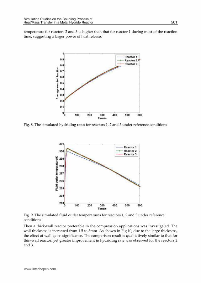
also supported by the comparison of fluid outlet temperature of the 3 reactors, see Fig.9.
With the same mass flow rate and inlet temperature for the fluid, the fluid outlet
www.intechopen.com
Simulation Studies on the Coupling Process of Heat/Mass Transfer in a Metal Hydride Reactor
561
temperature for reactors 2 and 3 is higher than that for reactor 1 during most of the reaction
time, suggesting a larger power of heat release.
Fig. 8. The simulated hydriding rates for reactors 1, 2 and 3 under reference conditions
Fig. 9. The simulated fluid outlet temperatures for reactors 1, 2 and 3 under reference conditions
Then a thick-wall reactor preferable in the compression applications was investigated. The
wall thickness is increased from 1.5 to 3mm. As shown in Fig.10, due to the large thickness,
the effect of wall gains significance. The comparison result is qualitatively similar to that for
thin-wall reactor, yet greater improvement in hydriding rate was observed for the reactors 2
and 3.
www.intechopen.com

Mass Transfer in Multiphase Systems and its Applications
562
Fig. 10. The simulated hydriding rates for reactors 1, 2 and 3 with larger wall thickness
The effect of wall material on the reaction rate depends not only on the thickness, but also on the operation conditions, especially those related to the transport and accumulation of the reaction heat. The simulation results for the case that air is used as the heat transfer fluid were shown in Fig.11.
Fig. 11. The simulated hydriding rates for reactors 1, 2 and 3 while using air as heat transfer fluid
Under this condition, a typical convection heat transfer coefficient of 50W/(m2·K) was set.
As can be seen, the hydriding rate gets much slower for all the 3 reactors, because the heat
exchange between the bed and fluid is not as sufficient as that for a reactor using water.
Moreover, it was found that the highest reaction rate is obtained by reactor 1 rather than
reactors 2 and 3, which seems unreasonable considering only the heat transfer. The
comparison of the heat capacity of wall for the 3 reactors in Fig.12 explained the simulation
results.
www.intechopen.com

Simulation Studies on the Coupling Process of Heat/Mass Transfer in a Metal Hydride Reactor
563
Fig. 12. The heat capacities for the tube wall of reactors 1, 2 and 3
Due to poor external heat transfer when using the air, the reaction heat can no longer be released rapidly and will be accumulated in the bed, even for the reactors 2 and 3. The notion was proved by the temperature contours in reactor 3 at certain moments, see Fig.13.
Fig. 13. The temperature contours of reactor 3 at the moment of 5, 20, 50 and 200s while using air as heat transfer fluid
Because of the heat accumulation, the reactor temperature is kept on a high level soon after the hydriding reaction starts. In this case, the temperature rise of the reactor depends more on the total heat capacity. Larger heat capacity limits the temperature fluctuation in the bed during the initial stage, and thus favors the proceeding of reaction. After a certain time elapses and the steady temperature distribution formed, such effect disappears and the same reaction rates were observed for all the 3 reactors, as shown in Fig.11.
www.intechopen.com
Mass Transfer in Multiphase Systems and its Applications
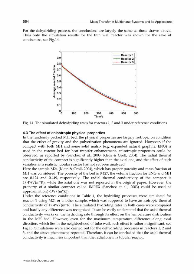
564
For the dehydriding process, the conclusions are largely the same as those drawn above. Thus only the simulation results for the thin wall reactor was shown for the sake of conciseness, see Fig.14.
Fig. 14. The simulated dehydriding rates for reactors 1, 2 and 3 under reference conditions
4.3 The effect of anisotropic physical properties In the randomly packed MH bed, the physical properties are largely isotropic on condition that the effect of gravity and the pulverization phenomena are ignored. However, if the compact with both MH and some solid matrix (e.g. expanded natural graphite, ENG) is used in the reactor bed for heat transfer enhancement, anisotropic properties could be observed, as reported by (Sanchez et al., 2003; Klein & Groll, 2004). The radial thermal conductivity of the compact is significantly higher than the axial one, and the effect of such variation in a realistic tubular reactor has not yet been analyzed. Here the sample M24 (Klein & Groll, 2004), which has proper porosity and mass fraction of MH was considered. The porosity of the bed is 0.427, the volume fraction for ENG and MH are 0.124 and 0.449, respectively. The radial thermal conductivity of the compact is 17.4W/(m*K), while the axial one was not reported in the original paper. However, the property of a similar compact called IMPEX (Sanchez et al., 2003) could be used as approximation(~1W/(m*K)). Under the reference conditions in Table 4, the hydriding processes were simulated for
reactor 1 using M24 or another sample, which was supposed to have an isotropic thermal
conductivity of 17.4W/(m*K). The simulated hydriding rates in both cases were compared
and hardly any difference was recognized. It can be easily understood that the axial thermal
conductivity works on the hydriding rate through its effect on the temperature distribution
in the MH bed. However, even for the maximum temperature difference along axial
direction, which lies in the neighborhood of tube wall, such effect is rather insignificant, see
Fig.15. Simulations were also carried out for the dehydriding processes in reactors 1, 2 and
3, and the above phenomena repeated. Therefore, it can be concluded that the axial thermal
conductivity is much less important than the radial one in a tubular reactor.
www.intechopen.com

Simulation Studies on the Coupling Process of Heat/Mass Transfer in a Metal Hydride Reactor
565
Fig. 15. The maximum temperature difference along axial direction for the reactors using sample M24 and isotropic sample
It is convenient to compare the reaction and transport characteristics of the reactors where different measures are taken for heat transfer enhancement, i.e. Aluminum foam and ENG compact. As shown in Fig.16, faster reaction rate was achieved in the latter reactor under reference conditions, although its axial thermal conductivity is even lower than that of reactor using Aluminum foam. The temperature in the reactor using ENG compact was indicted in Fig.17. More uniform distribution of temperature was found when compared with Fig.5. The reaction driving force is determined by bed pressure and equilibrium pressure(largely determined by temperature), as can be seen in equation (12). Considering the small pressure drop in the reactor, we can conclude that uniform temperature results in uniform reaction, which is favorable for the operation of MH reactor. In a word, MH reactor using ENG compact shows superior performance to the one using Aluminum foam.
Fig. 16. The simulated hydriding rates for the reactor 1 using Aluminum foam or ENG compact
www.intechopen.com

Mass Transfer in Multiphase Systems and its Applications
566
Fig. 17. The temperature contours in reactor 1 using ENG compact at the moment of 5, 20, 50, 200s during hydriding process (K)
5. Conclusion
A mathematical model for the hydriding/dehydriding process in a realistic MH reactor was established, in which the distributed and anisotropic physical properties could be easily handled. Numerical solution of the model was implemented by the FVM procedure, and the model was validated using the literature data. The model was applied for the simulation study of a tubular type MH reactor packed with LaNi5, and the following conclusions were drawn: 1. Heat transfer rather than mass transfer controls the actual reaction rate for the MH
reactor under discussion. 2. The effect of wall material on the hydriding/dehydriding rate of a MH reactor depends
on two factors, i.e. the thermal conductivity and heat capacity. 3. When the external convection heat transfer is sufficient, the effect of wall depends more
on its thermal conductivity, larger λ suggests better heat transfer and more rapid reaction.
4. When air is used as the heat transfer fluid, heat capacity of the wall becomes important as the external convection heat transfer gets poor. The reactor with larger heat capacity shows smaller temperature fluctuation and slightly higher reaction rate in the initial stage.
5. In comparison to the radial thermal conductivity, the axial one of the MH bed is basically unimportant in a tubular reactor. Therefore, the measures merely achieving significant heat transfer enhancement in radial direction, e.g. ENG compact, is recommended for use.
6. Nomenclature
A parameter in P-c-T equation
B parameter in P-c-T equation [ ]K
www.intechopen.com

Simulation Studies on the Coupling Process of Heat/Mass Transfer in a Metal Hydride Reactor
567
cp specific heat capacity [ /( )]J kg K⋅
pd diameter of particles [m]
E activation energy [ / ]J mol
f function
g function
h convective heat transfer coefficient 2[ /( )]W m K⋅
HΔ reaction heat 2[ / ]J molH
H
M
⎡ ⎤⎢ ⎥⎣ ⎦ mole ratio of stored hydrogen to host metal
k reaction rate constant 1[ ]s−
K permeability 2[ ]m
m•
source term from reaction 3[mol /( )]m s⋅
L length of the tubular reactor [ ]m
M molecular weight [ / ]kg mol
P pressure [ ]Pa
q mass flow rate [ / ]kg s
r r-coordinate in the radial direction [ ]m
gR general gas constant [ /( )]J mol K⋅
S source term
t time [ ]s
T temperature [ ]K
U→
gas velocity [ / ]m s
X reacted fraction
z z-coordinate in the axial direction [ ]m
Greek symbols β hysteresis factor in P-c-T equation
Γ coefficient for diffusion-like process ε volume fraction
θ plateau flatness factor in P-c-T equation
0θ plateau flatness factor in P-c-T equation
λ thermal conductivity [ /( )]W m K⋅
μ dynamic viscosity [ ]Pa s⋅
ρ density 3[ / ]kg m
ϕ general scalar quantity
Subscripts a absorption, namely hydriding
www.intechopen.com

Mass Transfer in Multiphase Systems and its Applications
568
Al Aluminum foam
b bulk
d desorption, namely dehydriding
e equilibrium
eff effective
ex exerted
f heat transfer fluid
g hydrogen gas
i inner
in inlet
MH metal hydride
o outer
sat saturated
w wall
7. References
Askri, F.; Jemni, A. & Ben Nasrallah, S. (2003). Study of two-dimensional and dynamic heat and mass transfer in a metal–hydrogen reactor. Int. J Hydrogen Energy, Vol.28, No.5 (537-557), ISSN: 0360-3199.
Berube, V.; Radtke, G.; Dresselhaus, M. & Chen, G. (2007). Size effects on the hydrogen storage properties of nanostructured metal hydrides: A review. Int. J Energy Research, Vol.31, No.6-7 (637-663), ISSN: 1099-114X.
Charton, S.; Corriou, J.P. & Schweich, D. (1999). Modeling of hydrogen isotopes separation in a metal hydride bed. Chemical Engineering Science, Vol.54, No.1 (103-113), ISSN: 0009-2509.
Choi,H. & Mills, A.F. (1990). Heat and mass transfer in metal hydride beds for heat pump applications. Int. J Heat Mass Transfer, Vol.33, No.6 (1281-1288), ISSN: 0017-9310.
Dhaou, H.; Askri, F.; Ben Salah, M.; Jemni, A.; Ben Nasrallah, S. & Lamloumi, J. (2007). Measurement and modeling of kinetics of hydrogen sorption by LaNi5 and two related pseudo-binary compounds. Int. J Hydrogen Energy, Vol.32, No.5 (576-587), ISSN: 0360-3199.
El Osery, I.A. (1983). Theory of the computer code ret1 for the calculation of space-time dependent temperature and composition properties of metal hydride hydrogen storage beds. Int. J Hydrogen Energy, Vol.8, No.3 (191-198), ISSN: 0360-3199.
Felderhoff, M. & Bogdanovic, B. (2009). High temperature metal hydrides as heat storage materials for solar and related applications. Int. J Molecular Sciences, Vol.10, No.1 (325-344), ISSN: 1422-0067.
Forde, T.; Maehlen, J.P.; Yartys, V.A.; Lototsky, M.V. & Uchida, H. (2007). Influence of intrinsic hydrogenation/dehydrogenation kinetics on the dynamic behavior of metal hydrides: A semi-empirical model and its verification. Int. J Hydrogen Energy, Vol.32, No.8 (1041-1049), ISSN: 0360-3199.
Jemni,A. & Ben Nasrallah, S. (1995). Study of two-dimensional heat and mass transfer during absorption in a metal-hydrogen reactor. Int. J Hydrogen Energy, Vol.20, No.1 (43-52), ISSN: 0360-3199.
www.intechopen.com

Simulation Studies on the Coupling Process of Heat/Mass Transfer in a Metal Hydride Reactor
569
Jemni, A. & Ben Nasrallah, S. (1995). Study of two-dimensional heat and mass transfer during desorption in a metal-hydrogen reactor. Int. J Hydrogen Energy, Vol.20, No.11 (881-891), ISSN: 0360-3199.
Kaplan, Y.; Ilbas, M.; Mat, M.D.; Demiralp, M. & Veziroglu, T.N. (2006). Investigations of thermal aspects of hydrogen storage in a LaNi5-H2 reactor. Int. J Energy Research, Vol.30, No.6 (447-458), ISSN: 1099-114X.
Kim, J.K.; Park, I.S.; Kim, K.J. & Gawlik, K. (2008). A hydrogen-compression system using porous metal hydride pellets of LaNi5-xAlx. Int. J Hydrogen Energy, Vol.33, No.2 (870-877), ISSN: 0360-3199.
Klein, H.P. & Groll, M. (2004). Heat transfer characteristics of expanded graphite matrices in metal hydride beds. Int. J Hydrogen Energy, Vol.29, No.14 (1503-1511), ISSN: 0360-3199.
Kuznetsov, A.V.; Vafai, K. (1995). Analytical comparison and criteria for heat and mass transfer models in metal hydride packed beds. Int. J Heat Mass Transfer, Vol.38, No.15 (2873-2884), ISSN: 0017-9310.
Laurencelle, F & Goyette, J. (2007). Simulation of heat transfer in a metal hydride reactor with aluminium foam. Int. J Hydrogen Energy, Vol.32, No.14 (2957-2964), ISSN: 0360-3199.
Li, Q.; Lin, Q.; Chou, K.C. & Jiang, L.J. (2004). A study on the hydriding-dyhydriding kinetics of Mg1.9Al0.1Ni. J Materials Science, Vol.39, No.1 (61-65), ISSN: 1573-4803.
Lloyd, G.; Razani, A. & Feldman, K.T. Transitional reactor dynamics affecting optimization of a heat-driven metal hydride refrigerator. Int. J Heat Mass Transfer, Vol.41, No.3 (513-527), ISSN: 0017-9310.
Mat, M.D.; Kaplan, Y. & Aldas, K. (2002). Investigation of three-dimensional heat and mass transfer in a metal hydride reactor. Int. J Energy Research, Vol.26, No.11 (973-986), ISSN: 1099-114X.
Meng, X.Y.; Bai, F.F.; Yang, F.S.; Bao, Z.W. & Zhang, Z.X. (2010). Study of integrated metal hydrides heat pump and cascade utilization of liquefied natural gas cold energy recovery system. Int. J Hydrogen Energy, Vol.35, No.13 (7236-7245), ISSN: 0360-3199.
Murthukumar, P.; Prakash Maiya, M. & Srinivasa Murthy, S. (2005). Experiments on a metal hydride based hydrogen compressor. Int. J Hydrogen Energy, Vol.30, No.8 (879-892), ISSN: 0360-3199.
Nakagawa, T.; Inomata, A.; Aoki, H. & Miura, T. (2000). Numerical analysis of heat and mass transfer characteristics in the metal hydride bed. Int. J Hydrogen Energy, Vol.25, No.4 (339-350), ISSN: 0360-3199.
Nishizaki, T.; Miyamoto, K. & Yoshida, K. (1983). Coefficients of performance of hydride heat pumps. J Less-Common Metals, Vol.89, No.2 (559-566), ISSN: 0022-5088.
Paya, J.; Linder, M.; Laurien, E. & Corberan, J.M. (2009). Dynamic model and experimental results of a thermally driven metal hydride cooling system. Int. J Hydrogen Energy, Vol.34, No.7 (3173-3184), ISSN: 0360-3199.
Qin, F.; Chen, J.P.; Lu, M.Q.; Chen, Z.J.; Zhou, Y.M. & Yang, K. (2007). Development of a metal hydride refrigeration system as an exhaust gas-driven automobile air conditioner. Renewable Energy, Vol. 32, No.12 (2034-2052), ISSN: 0960-1481.
Ron, M. (1999). The normalized pressure dependence method for the evaluation of kinetic rates of metal hydride formation/decomposition. J Alloys and Compounds, Vol.283, No.1-2 (178-191), ISSN: 0925-8388.
www.intechopen.com

Mass Transfer in Multiphase Systems and its Applications
570
Sanchez, A.R.; Klein, H.P.; Groll, M. (2003). Expanded graphite as heat transfer matrix in metal hydride beds. Int. J Hydrogen Energy , Vol.28, No.5 (515-527), ISSN: 0360-3199.
Sandrock, G. & Bowman, R.C. (2003). Gas-based hydride applications: recent progress and future needs. J Alloys and Compounds, Vol.356-357, No.1-2 (794-799), ISSN: 0925-8388.
Schweppe, F.; Martin, M.; Fromm, E. (1997). Model on hydride formation describing surface control, diffusion control and transition regions. Journal of Alloys and Compounds, Vol.261, No.1-2 (254-258), ISSN: 0925-8388.
Sun, D.W. & Deng, S.J. (1988). Study of the heat and mass transfer characteristics of metal hydride beds. J. Less- Common Metals, Vol.141, No.1 (37-43), ISSN: 0022-5088.
Sun, D.W. & Deng, S.J. (1990). Theoretical descriptions and experimental measurements on the effective thermal conductivity in metal hydride powder beds. J Less-Common Metals, Vol.160, No.2 (387-395), ISSN: 0022-5088.
Tao, W.Q. (2001). Numerical heat transfer(in Chinese, 2nd edition). Xi’an Jiaotong University Press, ISBN: 978-7-5605-1436-9, Xi’an, P.R.China.
Wang, Y.Q.; Yang, F.S.; Meng, X.Y.; Guo, Q.F.; Zhang, Z.X.; Park, I.S.; Kim, S.W. & Kim, K.J. (2010). Simulation study on the reaction process based single stage metal hydride thermal compressor. Int. J Hydrogen Energy, Vol.35, No.1 (321-328), ISSN: 0360-3199.
Yang, F.S.; Meng, X.Y.; Deng, J.Q.; Wang, Y.Q. & Zhang, Z.X. (2008). Identifying heat and mass transfer characteristics of metal- hydrogen reactor during adsorption – Parameter analysis and numerical study. Int. J Hydrogen Energy, Vol.33, No.3 (1014-1022), ISSN: 0360-3199.
Yang, F.S.; Meng, X.Y.; Deng, J.Q; Wang, Y.Q. & Zhang, Z.X. (2009). Identifying heat and mass transfer characteristics of metal hydride reactor during adsorption – Improved formulation about parameter analysis. Int. J Hydrogen Energy, Vol.34, No.4 (1852-1861), ISSN: 0360-3199.
Yang, F.S.; Wang, G.X.; Zhang, Z.X.; Meng, X.Y. & Rudolph, V. (2010). Design of the metal hydride reactors- A review on the key technical issues. Int. J Hydrogen Energy, Vol.35, No.8 (3832-3840), ISSN: 0360-3199.
Yang, F.S.; Wang, G.X.; Zhang, Z.X. & Rudolph, V. (2010). Investigation on the influences of heat transfer enhancement measures in a thermally driven metal hydride heat pump. Int. J Hydrogen Energy, Vol.35, No.18 (9725-9735), ISSN: 0360-3199.
www.intechopen.com

Mass Transfer in Multiphase Systems and its ApplicationsEdited by Prof. Mohamed El-Amin
ISBN 978-953-307-215-9Hard cover, 780 pagesPublisher InTechPublished online 11, February, 2011Published in print edition February, 2011
InTech EuropeUniversity Campus STeP Ri Slavka Krautzeka 83/A 51000 Rijeka, Croatia Phone: +385 (51) 770 447 Fax: +385 (51) 686 166www.intechopen.com
InTech ChinaUnit 405, Office Block, Hotel Equatorial Shanghai No.65, Yan An Road (West), Shanghai, 200040, China
Phone: +86-21-62489820 Fax: +86-21-62489821
This book covers a number of developing topics in mass transfer processes in multiphase systems for avariety of applications. The book effectively blends theoretical, numerical, modeling and experimental aspectsof mass transfer in multiphase systems that are usually encountered in many research areas such aschemical, reactor, environmental and petroleum engineering. From biological and chemical reactors to paperand wood industry and all the way to thin film, the 31 chapters of this book serve as an important reference forany researcher or engineer working in the field of mass transfer and related topics.
How to referenceIn order to correctly reference this scholarly work, feel free to copy and paste the following:
Fusheng Yang and Zaoxiao Zhang (2011). Simulation Studies on the Coupling Process of Heat/Mass Transferin a Metal Hydride Reactor, Mass Transfer in Multiphase Systems and its Applications, Prof. Mohamed El-Amin(Ed.), ISBN: 978-953-307-215-9, InTech, Available from: http://www.intechopen.com/books/mass-transfer-in-multiphase-systems-and-its-applications/simulation-studies-on-the-coupling-process-of-heat-mass-transfer-in-a-metal-hydride-reactor