
Simulation of Horizontal Centrifugal Casting: Mold Filling...
9
© 2014 ISIJ 266 ISIJ International, Vol. 54 (2014), No. 2, pp. 266–274 Simulation of Horizontal Centrifugal Casting: Mold Filling and Solidification Jan BOHACEK, 1) * Abdellah KHARICHA, 2) Andreas LUDWIG 1) and Menghuai WU 2) 1) Dept. of Metallurgy, Montanuniversitaet Leoben, Franz-Joseph Strasse 18, Leoben, 8700 Austria. 2) Christian Doppler Lab for Advanced Simulation of Solidification and Melting, Dept. of Metallurgy, Montanuniversitaet Leoben, Franz-Joseph Strasse 18, Leoben, 8700 Austria. (Received on July 8, 2013; accepted on November 28, 2013) In order to simulate the mold filling and solidification of the outer shell of large work rolls being cast by horizontal centrifugal casting, the shallow water equations were adopted to solve the 2D average flow dynamics of the melt spreading inside the cylindrical mold. The model accounts for centrifugal force, Coriolis force, shear force, gravity and convective and diffusive energy transport. The solidification front was tracked by fulfilling the Stefan condition. Radiative and convective heat losses were included from both, the free surface and the outer wall of the mold. By introducing a stochastic factor to account for the irregular filling jet behavior an uneven spreading of liquid from the center of the mold towards the extrem- ities was predicted. Thus, the formation of the first solid layer also happens unevenly. However, when the mold is covered everywhere with a solid layer, the solidification rate decreases and further filling increases the height of the liquid layer. With increase liquid height the amplitude of the free surface waves also increases. KEY WORDS: horizontal centrifugal casting; work roll; shallow water equations; Coriolis force; Stefan con- dition; mold deformation. 1. Introduction The centrifugal casting process has two distinct branches, the vertical and horizontal centrifugal (or spin) casting, where vertical and horizontal define the placement of the axis of revolution of the mold. The vertical centrifugal cast- ing is commonly used for casting non-cylindrical parts such as valves, propellers, sprockets etc. On the other hand, cylindrical parts such as pipes, sleeves, tubes are cast using the second technique provided that the length of the casting is greater than the diameter and that the casting contains a cylindrical bore through. The main difference between the vertical and horizontal centrifugal casting is in the resultant force acting on the melt. With a vertical mold axis the resul- tant force is constant, whereas with a horizontal mold axis the centrifugal force is periodically disturbed by the gravity and by inherent vibrations. A common advantage of both centrifugal casting processes dwells in obtaining superior mechanical properties of the products compared to the con- ventional gravity castings. 1) Now, putting the vertical cen- trifugal casting 2) aside, the horizontal centrifugal casting can be discussed in more details. A schematic of the process is shown in Fig. 1. The filling starts with the relatively cold mold (~433 K) already rotating at constant rpm (~680 rpm). Solidification occurs immediately, when the melt firstly hits the mold wall. A cloud of fine crystals nucleate close to the mold. Due to the interaction between the forces of inertia and the extreme shear force, nuclei are evenly distributed in the bulk, where they mostly survive and continue growing, which then results in a very fine structure throughout. 3) Pos- sible columnar crystals solidifying from the mold wall are usually washed out by severe tangential forces and further support the fine structure. Next, the centrifugal force can easily exceed 100 G in magnitude, which helps to suppress the shrinkage and pushes possible inclusions and impurities towards the mold center due to the density difference. The second phenomenon enhancing mechanical properties is the inherent vibration, which promotes the solidification rate and enhances turbulence. The angular frequency Ω has to be carefully chosen. Too low Ω causes the liquid to fail to adhere to the mold wall, which is known as “raining” i.e. a curtain of metal droplets falling down from the top of the * Corresponding author: E-mail: [email protected] DOI: http://dx.doi.org/10.2355/isijinternational.54.266 Fig. 1. A schematic of the horizontal centrifugal casting of an outer shell of a large work roll. (Online version in color.)
Transcript of Simulation of Horizontal Centrifugal Casting: Mold Filling...

© 2014 ISIJ 266
ISIJ International, Vol. 54 (2014), No. 2, pp. 266–274
Simulation of Horizontal Centrifugal Casting: Mold Filling and Solidification
Jan BOHACEK,1)* Abdellah KHARICHA,2) Andreas LUDWIG1) and Menghuai WU2)
1) Dept. of Metallurgy, Montanuniversitaet Leoben, Franz-Joseph Strasse 18, Leoben, 8700 Austria.2) Christian Doppler Lab for Advanced Simulation of Solidification and Melting, Dept. of Metallurgy, MontanuniversitaetLeoben, Franz-Joseph Strasse 18, Leoben, 8700 Austria.
(Received on July 8, 2013; accepted on November 28, 2013)
In order to simulate the mold filling and solidification of the outer shell of large work rolls being cast byhorizontal centrifugal casting, the shallow water equations were adopted to solve the 2D average flowdynamics of the melt spreading inside the cylindrical mold. The model accounts for centrifugal force,Coriolis force, shear force, gravity and convective and diffusive energy transport. The solidification frontwas tracked by fulfilling the Stefan condition. Radiative and convective heat losses were included fromboth, the free surface and the outer wall of the mold. By introducing a stochastic factor to account for theirregular filling jet behavior an uneven spreading of liquid from the center of the mold towards the extrem-ities was predicted. Thus, the formation of the first solid layer also happens unevenly. However, when themold is covered everywhere with a solid layer, the solidification rate decreases and further filling increasesthe height of the liquid layer. With increase liquid height the amplitude of the free surface waves alsoincreases.
KEY WORDS: horizontal centrifugal casting; work roll; shallow water equations; Coriolis force; Stefan con-dition; mold deformation.
1. Introduction
The centrifugal casting process has two distinct branches,the vertical and horizontal centrifugal (or spin) casting,where vertical and horizontal define the placement of theaxis of revolution of the mold. The vertical centrifugal cast-ing is commonly used for casting non-cylindrical parts suchas valves, propellers, sprockets etc. On the other hand,cylindrical parts such as pipes, sleeves, tubes are cast usingthe second technique provided that the length of the castingis greater than the diameter and that the casting contains acylindrical bore through. The main difference between thevertical and horizontal centrifugal casting is in the resultantforce acting on the melt. With a vertical mold axis the resul-tant force is constant, whereas with a horizontal mold axisthe centrifugal force is periodically disturbed by the gravityand by inherent vibrations. A common advantage of bothcentrifugal casting processes dwells in obtaining superiormechanical properties of the products compared to the con-ventional gravity castings.1) Now, putting the vertical cen-trifugal casting2) aside, the horizontal centrifugal casting canbe discussed in more details. A schematic of the process isshown in Fig. 1. The filling starts with the relatively coldmold (~433 K) already rotating at constant rpm (~680 rpm).Solidification occurs immediately, when the melt firstly hitsthe mold wall. A cloud of fine crystals nucleate close to the
mold. Due to the interaction between the forces of inertiaand the extreme shear force, nuclei are evenly distributed inthe bulk, where they mostly survive and continue growing,which then results in a very fine structure throughout.3) Pos-sible columnar crystals solidifying from the mold wall areusually washed out by severe tangential forces and furthersupport the fine structure. Next, the centrifugal force caneasily exceed 100 G in magnitude, which helps to suppressthe shrinkage and pushes possible inclusions and impuritiestowards the mold center due to the density difference. Thesecond phenomenon enhancing mechanical properties is theinherent vibration, which promotes the solidification rateand enhances turbulence. The angular frequency Ω has to becarefully chosen. Too low Ω causes the liquid to fail toadhere to the mold wall, which is known as “raining” i.e. acurtain of metal droplets falling down from the top of the
* Corresponding author: E-mail: [email protected]: http://dx.doi.org/10.2355/isijinternational.54.266
Fig. 1. A schematic of the horizontal centrifugal casting of an outershell of a large work roll. (Online version in color.)
ISIJ International, Vol. 54 (2014), No. 2
267 © 2014 ISIJ
mold.4) On the other hand, excessive angular frequenciesgenerally lead to inadmissible strong vibrations, which mayresult in longitudinal cracks caused by the hoop stress in theinitially solidified shell. Besides, even for very little densitydifference between two alloy elements a too high angularfrequency Ω can result in significant segregation.5) For thisreasons, the angular frequency Ω along with many otherprocess parameters such as the pouring temperature, pouringrate, the way how the melt is poured etc. require an optimalcontrol.
Some papers written by other researchers on this topicwere oriented on the experimental trials, usually some coldexperiments; some papers were dealing with mathematicalmodels and numerical simulations. A paper6) describing var-ious flow regimes during the horizontal centrifuging wasdone to study the influence of the angular frequency Ω andthe liquid height h on waves appearing on the free surface.It was surprisingly found that with increasing the angularfrequency the free surface was more disturbed mainly dueto inherent mechanical vibrations. For low Ω the free sur-face formed purely cylindrical pattern. With increasing Ω afree surface pattern was passing through the regime withhelical waves, then orthogonal, and eventually “orangeskin” waves. Mathematical formulas were stated for vibra-tions and axial deformation of the mold to analyticallyinvestigate free surface patterns. Recently, in-situ experi-ments were performed,7) in which the Succinonitrile-1 mass% water alloy was poured in the rotating glass celland the movement of the equiaxed crystals was observed bymeans of the high-speed camera. They found that the rela-tive path of the arbitrarily chosen equiaxed crystal associat-ed with a fix point on the mold oscillates and travels in theanti-rotational direction. This phenomenon can be attributedto the interaction between the inertia of the crystal and the3D flow influenced by effects of the gravity and vibrations.Very interesting experimental work8) comparing mechanicalproperties of the Al–Si specimens cast using the centrifugaland gravitational casting technique was done revealing thatthe tensile and rupture strength was increased for the cen-trifugal castings. The authors claimed that it is possible tosplit effects of the centrifugal force into three separatemechanisms: the centrifugal pressure, the inherent vibration,and the fluid dynamics.
In addition to these experimental works, not many numer-ical studies were devoted to the horizontal centrifugal cast-ing. In,9) a full 3D simulation of the horizontal centrifugalcasting was performed in the commercial software STAR-CD V4 using the VOF method to track the free surface. Thewhole cylindrical domain was meshed with rather coarsepolyhedral elements, which allowed notably large time step(~0.01). Only the flow was solved without taking intoaccount the heat transfer and solidification. Results fromsimulations showed roughly how the melt is spreading dur-ing the filling, but no details are given on how the fillingwas realized and whether the model could capture some freesurface patterns or not. Next, a solidification model10) wasdeveloped for a description of the centrifugal casting pro-cess of a metal matrix composite reinforced by dispersedceramic particles. The numerical model ignored the flow,but forces acting on the particles were taken into account bymeans of solving ODE for the force balance. A planar solid-
ification front was considered. A study on a similar topic11)
was performed, in which the solidification of the centrifu-gally cast particle reinforced metal matrix composite wasinfluenced by the particles travelling through the liquid met-al matrix. From the force balance on the particle, they foundthat the Coriolis force can be disregarded when the particlediameter d or the angular frequency Ω is small. In otherwords, the Coriolis force can be only neglected when theratio between the coefficient 2ρPVΩ (related to the Coriolisforce) and the coefficient 6πμd (related to the drag force) ismuch smaller than unity. In general, the Coriolis force can-not be however neglected. A full 3D numerical model12) ofthe horizontal centrifugal casting was recently introducedsimulating the interface between the metal and air recon-structed by the VOF method for tracking free surfaces. Themain goal was to study the effect of two different filling sys-tems on the temperature distribution on the outer wall of themold. It was found that with the filling arm moving to andfro more uniform temperature distribution can be achievedcompared to the classical static filling. Another numericalstudy13) concerning the horizontal centrifugal casting name-ly casting of pipes was done using the commercial CFDpackage FLOW3D. In order to avoid extremely low timesteps, momentum equations were solved in the rotatingframe of reference. However, due to a very small wall-to-length thickness ratio, one simulation still took considerablylong time (~20 days).
Nowadays, the commercial CFD packages are along withhyper-threading computing very powerful tools, which canbe successfully used to simulate many physical and engi-neering processes. However, the importance of the properchoice of the equations to be solved and how it should besolved still remains inarguable. In this particular case of thehorizontal centrifugal casting of a work roll we believe it ispractically impossible to simulate the full casting process(~35 min) by solving the full 3D Navier-Stokes equationsfor two immiscible phases (the metal and air) in a reason-able time. On the other hand, we are convinced that the mainfeatures of the flow and the whole casting can be reliablycaptured with the help of the 2D shallow water equations(SWE).14,15) The original 2D SWE were derived from the 3DN-S equations assuming that the pressure is strictly hydro-static and that the vertical components in the momentumequation for the radial direction can be ignored. For thecharacteristic length scale much greater than the character-istic height it is a very good approximation. In our systemthe order of magnitude of the ratio between the characteris-tic height (liquid metal height) and the characteristic lengthscale is 0.01 and thus; the simplification by assuming a shal-low water flow is reasonable. It is important to note that noassumption is made about the amplitude of waves. The SWEstill retains the nonlinear convective terms from the N-Sequations. In general, the SWE are used for modeling pur-poses in oceanography,16) river management,17) and meteo-rology.
In this paper modified SWE are introduced for simulatingthe average flow dynamics of the melt inside a horizontallyrotating mold. The flow is exposed to some sort of vibra-tions induced by a poor roundness of the mold (or a massimbalance) and a mold deformation due to thermal effects.The flow equations are coupled with a solidification model

© 2014 ISIJ 268
ISIJ International, Vol. 54 (2014), No. 2
assuming a microscopically planar solid-liquid interface.The diffusive and convective energy transport is solved inthe liquid taking into account convective and radiative heatlosses from the free surface. A simple heat diffusion modelis applied in the solidifying shell and the mold. In Fig. 2, ageneral configuration demonstrates aspects of the SWEmodel such as a melt flowing over a solidifying shell, heattransfer to the mold, and heat losses from the free surfaceand the outer wall of the mold.
2. Model Description
The centrifugal force is evidently the most dominantforce (~100 G) always pushing the liquid towards the moldwall. From observations during the real casting the liquidperfectly adhered to the rotating mold even during first stagesof the filling. This suggests solving the flow in the rotatingframe of reference i.e. taking into account fictitious forcessuch as the centrifugal force and Coriolis force. The SWEwere derived in the Cartesian coordinate system constructedby unfolding the inner wall of the mold into the x-y plane,where x and y denote the axial and the circumferential posi-tion. Despite the cylindrical geometry, the Cartesian coordi-nate system was chosen mainly due to the rather small ratiobetween the liquid height h and the mold radius R. The mod-el assumptions are summarized below:
• The momentum equation can be written in the rotatingframe of reference due to the high centrifugal force(~100 G).
• The radial momentum is negligible compared to themomentum in the axial and the tangential direction ofthe cylindrical mold. Higher order terms in the asymp-totic series of the static pressure can be neglected andonly the hydrostatic pressure is retained.
• A fully developed laminar flow is assumed; therefore,a parabolic velocity profile is forced within the liquidheight h (Fig. 2) with a no slip boundary condition onthe underlying topography and zero stress on the freesurface.
• Surface tension effects can be neglected.The continuity equation remains unchanged for our con-
figuration and takes the form:
, ............... (1)
where h is the liquid height, x and y denote the axial and tan-gential direction, and u and v are respective components ofmass weighted average of the velocity. In the axial direction,the velocity u is defined by:
. ............................ (2)
The mass weighted average v of the velocity in the tangen-tial direction is computed analogically. The momentumequations for both directions x and y are given by:
... (3)
and
, ... (4)
where the terms on the left hand side represent the inertiaforces including the centrifugal force Fc and Coriolis forceFC. On the right hand side, Fτ denotes the shear force. Fg
stands for the gravity force (possibly perturbed by vibra-tions). Obviously, the centrifugal force acts purely in theradial direction, but its effect emerges in the momentumequations for x and y direction. Thus, any acceleration act-ing in the radial direction needs to be firstly expressed as theintegral of the equivalent hydrostatic pressure over the liq-uid height h. Then the gradient of such an integral gives thecorrect x and y components of the corresponding force.Components of the centrifugal force exerted over the liquidare defined by:18)
,................. (5)
where R is the inner radius of the mold and δ is the heightof the solidifying shell. For the derivation of the Coriolisforce dependent on the relative velocity we introduce anadditional assumption on the velocity profile within the liq-uid height h. We expect the flow to be fully developed lam-inar. Hence, a parabolic velocity profile was considered witha no slip boundary condition on the wall and zero frictionon the free surface. In the case of a perfectly cylindricalmold, the Coriolis force acts only radially and becomes:18)
............. (6)
From Eq. (6) it is clear that when the relative motion of theliquid is in the rotational direction, the Coriolis force pushesthe liquid towards the mold wall and vice versa. Next, sincethe relative velocity is maximal on the free surface and zeroon the underlying topography, the Coriolis force should bemore important at the free surface than on the solid relief.This is indicated by the analytical constants 5/2 and 2 by theterms with the gradient of the liquid height h and the solidheight δ, respectively. The assumption of a parabolic veloc-ity profile is also used in derivation of the bed shear stress19)
for the Newtonian fluid. The shear force invoked by the bedshear stress acting in the axial direction can be written as:
Fig. 2. A schematic of the SWE model. (Online version in color.)
∂ ( )∂
+∂ ( )∂
+∂ ( )∂
=ρ ρ ρh
t
hu
x
hv
y0
u u z dzh
= ( )+
∫δδ
∂ ( )∂
+∂ ( )∂
+∂ ( )∂
+ + = +ρ ρ ρ
τ
hu
tu
hu
xv
hu
yF F F Fcx Cx gx x
∂ ( )∂
+∂ ( )∂
+∂ ( )∂
+ + = +ρ ρ ρ
τ
hv
tu
hv
xv
hv
yF F F Fcy Cy gy y
F R h hc = − −( )∇ +( )ρ δ δΩ2
F h v h v h vC = ∇ + ∇ + ∇⎛⎝⎜
⎞⎠⎟ρ δΩ
5
22
5
4

ISIJ International, Vol. 54 (2014), No. 2
269 © 2014 ISIJ
,................................ (7)
where μ is the dynamic viscosity (~0.006 Pa s) and ρ is thedensity (~6 800 kg/m3). The shear force in the tangentialdirection is defined using the same formula (Eq. (7)) exceptthat the velocity component u is replaced by the velocitycomponent v. The shear force Fτ plays an important role andbalances the centrifugal force, when the liquid height hdiminishes. Finally, the gravity force Fg has components inboth x and y directions; however, it is prevailing in the y(tangential direction). In the axial direction the gravity forceFgx becomes:
. ................. (8)
In the tangential direction, the component Fgy of the gravityforce becomes:
, ... (9)
where g is the gravitational acceleration (~9.81 m/s2) and tis the current time. In Eqs. (8) and (9), the terms with theslope of the free surface represent the gradient componentsof the hydrostatic pressure integrated over the liquid heighth. In other words, in the SWE these terms correctly reflectthe effect of the radial component of the gravitational accel-eration g, which has an impact on the flow in both, the axialand the tangential, directions. As already discussed, the realcasting is accompanied by inherent vibrations, which areinduced by a poor circularity of the carrying rollers or thetracks, and also by deformation of the mold axis due topouring the hot metal inside the mold. In the numericalmodel, the vibrations are simply applied by perturbing thegravity force, whereas the mold deformation modifies allother forces except of the shear force Fτ . The mold defor-mation was realized by assuming the axis following a sinefunction with the nodes in the position of carrying rollersand the antinode in the center of the mold representing thelowest axial mode shape of a vibrating cylindrical shell.20)
Higher axial mode shapes were not considered in this study.The exaggerated picture of such an imperfect mold is shownin Fig. 3. Details on the derivation of the SWE including theinfluence of the vibrations and mold deformation are givenin our papers.21,22) The first paper21) is focused on the inves-tigation of free surface patterns influenced by vibrations andaxial mold deformations. Free surface patterns were studiedon the initially uniform distribution of the liquid height h.
Neither the solidification nor the mold filling were dis-cussed. The second paper22) deals with the solidification ofthe initially uniform thickness of the liquid and analyses theeffect of different heat transfer mechanisms on heat lossesfrom the free surface inside the mold. The mold filling wasnot included in the model.
Concerning the solidification model, we assume that theliquid solidifies exclusively from the mold wall and thatthere is no slip and also no thermal resistance between thesolidifying shell and the mold. Further, it is known that forPrandtl number less than unity, the hydrodynamically fullydeveloped flow is also thermally fully developed. In otherwords, in our case we believe that the thermal diffusivity ismuch stronger than the viscous forces; therefore, the ther-mally fully developed flow is considered. Such a flow ischaracterized by a parabolic temperature profile (Fig. 1).Further assumptions for the solidification model can beitemized as the following:
• A planar solid/liquid interface is considered betweenthe solid and the liquid (s/l). At the current stage of themodel, a possible mushy zone is not accounted for.
• The solidifying shell is perfectly attached to the inter-nal mold wall; hence, it rotates with the same angularfrequency Ω as the mold. In other words, there is novelocity slip between the mold and the solidifyingshell.
• Although a separating refractory material (ZrO2) isused to separate mold from the casting, a zero thermalresistance is currently considered.
• Heat fluxes are dominant in the radial direction due tothe high pouring temperature (~1 755 K) and relativelylow initial temperature of the mold (~ 433 K). For thisreason, the heat diffusion equation is simplified andsolved only in the radial direction. Lateral heat fluxesare neglected.
• Convective and radiative heat losses are modeledinside and outside the mold. During the real casting themold fronts are insulated by sand cores; therefore, theheat losses from the fronts are neglected.
In the liquid, the heat advection-diffusion equation (Eq.(10)) is solved for the average temperature given by:
. .......................... (9)
The heat advection-diffusion equation can be written as:
,
........................................ (10)
where α is the thermal diffusivity and ST is the source termdue to solidification and heat transfer to the mold. In thepresent study the thermal diffusivity α is kept constant andthe same for the liquid, solid, and mold (~5.88e-06 m2/s). Inthe future, the effective thermal diffusivity will be imple-mented in order to account for the variable thermal resistancedue to the shell shrinkage23) and the insulating refractorymaterial (ZrO2). The s/l interface of the solidifying shell issupposed to be planar fulfilling the Stefan condition24) givenby:Fig. 3. An exaggerated schematic of the deformed mold for Case B.
(Online version in color.)
Fu
hτ μ= −3
F gh th
xgx = − ( )∂ +( )
∂ρ
δcos Ω
F gh th
y
h
Rtgy = − ( )
∂ +( )∂
+ −⎛⎝⎜
⎞⎠⎟ ( )
⎛
⎝⎜⎜
⎞
⎠⎟⎟ρ
δcos sinΩ Ω1
2
T
Th
T z dzh
= ( )+
∫1
δ
δ
∂ ( )∂
+∂ ( )∂
+∂ ( )∂
=∂∂
∂∂
+∂∂
∂∂
⎛
⎝⎜⎜
⎞
⎠⎟⎟ +
hT
t
hT
xu
hT
yv
xh
T
x yh
T
ySTα α

© 2014 ISIJ 270
ISIJ International, Vol. 54 (2014), No. 2
, ...................... (11)
where Lf is the latent heat (~250 kJ/kg), c is the velocity ofthe s/l interface normal to the interface and the right handside denotes the net heat flux through the s/l interface. Thetemperature of the s/l interface corresponds to the tempera-ture of liquidus TLIQ (~1 586 K).The subscripts s and ldenote the solid and the liquid. The thermal conductivity kis constant (~30 W/(m K)) and same for both, the solid andliquid. The same holds for the density. The Stefan conditionis coupled with the 1D heat equation, which is solvednumerically on each quadrilateral element of the 2D gridand in cylindrical coordinates has the following form:
. ....................... (12)
Equation (12) describes the heat conduction through thesolidifying shell to the mold. Only the 1D heat equation issolved because the lateral heat fluxes are compared to theradial heat fluxes negligible. The Dirichlet boundary condi-tion is applied on the solid/liquid interface (Tl =1 586 K). Onthe outer wall of the mold the Neumann boundary conditionis employed representing convective and radiative heat loss-es (described below). The convective and radiative heattransfer from the free surface inside the mold was taken intoaccount. The convective losses were simplified by consideringa constant heat transfer coefficient HTCin of 100 W/(m2K).Outside of the mold convective heat losses were also account-ed for, but due to higher circumferential velocity the heattransfer coefficient HTCout was increased (~150 W/(m2K)).The model of the radiative heat transfer inside the mold issplit into two parts. The first part denotes the heat losses viaextremities, whereas the second part denotes the heatexchange inside the mold due to the fact that some regionsare hotter (or colder) than others. The theory of a black bodywas applied to simplify the problem.25) The radiative heatlosses via extremities (mold openings) from each surfaceelement were formulated as the following:
,................. (13)
where A is the area of the quadrilateral free surface element,σ is the Stefan-Boltzmann constant (~5.67e-08 W/(m2K4)),T is the temperature of the free surface and Ta is the temper-ature of the ambient (~323 K). Fw represents a geometricalresistance or a view factor, which generally depends on thedistance between two radiating surfaces and angles betweenthem. Unfortunately, even for this simple case of a cylindri-cal mold with two openings, the view factor Fw cannot bedetermined analytically. A numerical approximation of theview factor Fw is however feasible26) and is given by thepolynomial of the fourth order as the following:
,................ (14)
where x is the axial position, which is zero at one extremity.The constants a, b, c, d, and e are –0.1539, 0.7795, –1.502,1.34, and 0.4981. The constants were determined for thespecific case with the mold internal radius R=0.372 m andthe mold length L=3.2 m. However, the view factor Fw isrelated to the actual shape of the free surface inside themold; therefore, it is time dependent. Qualitatively we can
say that as the liquid height h increased during the filling,the radiative heat exchange inside the mold becomes moreimportant, whereas the radiative heat losses via extremitiesdiminish. On the other hand, the percentage rate of changeof the view factor Fw is small. Therefore, rather than apply-ing computationally expensive approximation of the con-stants in Eq. (13) every time step, we accepted a certainerror and used the time independent constants a, b, c, d, ande. The summation rule applies for any enclosure; therefore,the view factor Fw can be used to determine the radiativeheat exchange inside the mold, which takes the followingform:
, ..................... (15)
where Tw is the mean surface temperature, which is deter-mined from the energy conservation inside the mold givenby:
. ..................... (16)
Using Eq. (15) the mean average temperature Tw becomes:
, .......................... (17)
in which we need to evaluate sums of FiwTi and Fiw over allgrid elements. The relation for the radiative heat losses fromthe outer wall of the mold is much simpler, since the viewfactor from an arbitrary surface element to the ambient isalways equal unity. The corresponding formula is given by:
. ...................... (18)
The filling of the mold was realized through a circular masssource in the center of the mold. Since the SWE were solvedin the rotating frame of reference, the mass source had totravel in the anti-rotational direction. From the observationsduring the real casting the momentum of the impinging jetpresumably did not have an effect on the initial formationof the liquid ring around the circumference (Fig. 4). In addi-tion, the filling jet evidently did not have sufficient momen-tum to penetrate through the initial liquid ring and comecloser to the mold extremities. Therefore, the momentum ofthe filling jet was ignored in the simulations. The profile of
ρL c kT
zkT
zfs l=
∂∂
−∂∂
∂∂
=∂∂
∂∂
⎛⎝⎜
⎞⎠⎟
T
t r rrT
rα1
Q A F T Trin
w a14 41= −( ) −( )σ
F ax bx cx dx ew = + + + +4 3 2
Fig. 4. An early stage of the filling (t<5 s); a filling jet emittingfrom the filling arm, splashing on the rotating inner wall ofthe mold (R=0.372 m, Ω =71.2 rad/s), and forming a ringaround the mold circumference. (Online version in color.)
Q AF T Trin
w w24 4= −( )σ
AF T Tw wi
σ 4 4
1
0−( ) ==∑
TF T
Fwiw i
iw
= ∑∑
4
Q A T Touta= −( )σ 4 4

ISIJ International, Vol. 54 (2014), No. 2
271 © 2014 ISIJ
the mass source for the filling jet was naturally approximat-ed by a normal distribution with the standard deviation σestimated from the real casting observations (~90 mm). Thereal footprint of the filling jet is however far away from asmooth normal distribution. Therefore, the profile of theimpingement density was perturbed by means of a Box-Muller transform around the center of the filling jet, whichis generally given by:
, .................. (19)
where U1 and U2 are randomly sampled numbers from theinterval (0, 1]. For a set of U1, U2 the resulting N numberfollows a normal distribution. Using this algorithm the ele-ments in the vicinity of the filling jet center were visited andfor each element a number of visits was counted. The ratiobetween a number of visits and total number of tries gave astrength s of the mass source term Sm, which takes the fol-lowing form:
, ............... (20)
where the time dependent exponential function applies tothe variable mass flow rate during the first 5 seconds of thecasting, after which the mass flow rate is kept constant of30 kg/s. Although the end of the filling was not reached inthe present simulation results, in the real casting the fillingis stopped at t=90 s.
Flow and thermal boundary conditions are summarized inTable 1. Second order discretization schemes were used fortime and space. The algorithm was stable for the convectivecondition CFL≤1. A computational domain for the flowcomputation consisted of 160×117 (the mold length L × themold circumference 2πR) orthogonal quadrilateral elements.The heat diffusion in the radial direction was performed on200 equally spaced grid points. The grid size dependencywas tested on a 1D cold flow simulation (without the solid-ification) of a collapsing liquid column hitting a solid obsta-cle. The tested number of grid points was 100, 300, and1 000 s. A wave speed was slightly overestimated for a smallnumber of grid points (100). For a larger number of gridpoints a wave speed error can be neglected (Fig. 5).
3. Results and Discussion
The list of dimensions used in simulations is the follow-ing: the length of the mold L of 3.2 m, the internal mold radi-us R of 0.372 m, and the mold wall thickness of 0.203 m.Material properties and other model settings were mentioned
in the previous section. As the initial conditions (t=0 s), weconsidered an empty mold rotating in the positive directionwith the angular frequency Ω of 71.2 rad/s. During the sim-ulation the angular frequency Ω was held constant, althoughin the real casting especially during the filling a certain dropin Ω is always recorded. At both extremities reflectiveboundary condition was applied for the flow and zero fluxfor the enthalpy. Two types of simulations were carried outdiffering only in the geometrical configuration. The Case Asimulation was performed assuming a perfectly cylindricalmold i.e. Eqs. (1)–(4) were solved, whereas the Case B sim-ulation was done for a slightly deformed mold with theamplitude of 2 mm at the antinode (Fig. 3). The results arepresented on the inner mold wall unfolded in the horizontalplane as depicted in Fig. 6.
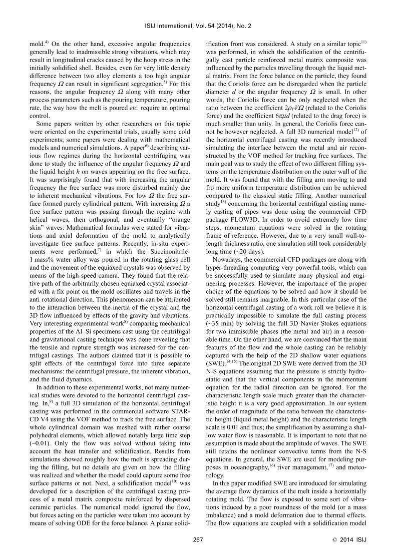
In the early stage of the filling, when the mass flow ratewas still rising according to the exponential function givenin Eq. (19) and the cold mold wall was not exposed to thehot liquid yet, the solidification rate is extremely high andnewly incoming liquid solidifies almost instantly. In Fig. 7,the actual free surface situation is visualized by means of thefree surface temperatures at t=0.5 s. The liquid free surfaceis depicted by the pear-shaped region, from where the posi-tion of the jet center is clear (shown as a circle). The fillingjet is travelling in the anti-rotational direction. In the neigh-boring zone the liquid solidified completely; thus, only thesolid can be seen. The rest of the surface was not touchedby the liquid metal, which is indicated by a significantlylower temperature very close to the initial temperature of the
Table 1. Boundary conditions.
location for BC flow BC thermal BC
free surface of the liquid
Q (convection,radiation)free surface of the solid (u(z), v(z)) = 0
dry inner wall of the wall –
outer wall of the mold –
s/l interface (u(z), v(z)) = 0 T=TLIQ
mold extremities Reflective wallhuGHOST = –hu Q=0 (adiabatic wall)
N U U= − ( )2 21 2ln cos π
S ts
Am = − −( )( )30 2035 1. exp
∂ ( )∂
∂ ( )∂
⎛
⎝⎜⎜
⎞
⎠⎟⎟ =
u z
z
v z
z, 0
Fig. 5. A free surface of the liquid after a collapse of the liquidcolumn with a wave reflection from the solid obstacle att=30 s; Initial state (t=0 s) shown in a smaller scale. (Onlineversion in color.)
Fig. 6. A cylindrical surface of the inner mold wall unfolded intothe horizontal plane.
© 2014 ISIJ 272
ISIJ International, Vol. 54 (2014), No. 2
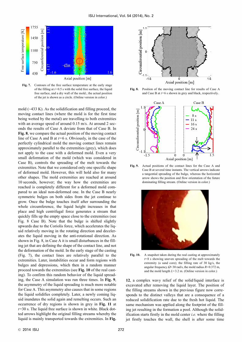
mold (~433 K). As the solidification and filling proceed, themoving contact lines (where the mold is for the first timebeing wetted by the metal) are travelling to both extremitieswith an average speed of around 0.15 m/s. At around 2 sec-onds the results of Case A deviate from that of Case B. InFig. 8, we compare the actual position of the moving contactline of Case A and B at t=6 s. Obviously, in the case of theperfectly cylindrical mold the moving contact lines remainapproximately parallel to the extremities (grey), which doesnot apply to the case with a deformed mold. Even a verysmall deformation of the mold (which was considered inCase B), controls the spreading of the melt towards theextremities. Note that we considered only one specific shapeof deformed mold. However, this will hold also for manyother shapes. The mold extremities are reached at around10 seconds, however; the way how the extremities arereached is completely different for a deformed mold com-pared to an ideal non-deformed one. In the Case B nearlysymmetric bulges on both sides from the jet continue togrow. Once the bulge touches itself after surrounding thewhole circumference, the liquid height increases in thatplace and high centrifugal force generates a stream thatquickly fills up the empty space close to the extremities (seeFig. 8 Case B). Note that the bulge is shifted slightlyupwards due to the Coriolis force, which accelerates the liq-uid relatively moving in the rotating direction and deceler-ates the liquid moving in the anti-rotational direction. Asshown in Fig. 8, in Case A it is small disturbances in the fill-ing jet that are defining the shape of the contact line, and notthe deformation of the mold. In the early stage of the casting(Fig. 7), the contact lines are relatively parallel to theextremities. Later, instabilities occur and form regions withbulges and depressions, which then in a random mannerproceed towards the extremities (see Fig. 10 of the real cast-ing). To confirm this random behavior of the liquid spread-ing, the Case A simulation was run three times. In Fig. 9,the asymmetry of the liquid spreading is much more notablefor Case A. This asymmetry also causes that in some regionsthe liquid solidifies completely. Later, a newly coming liq-uid inundates the solid again and remelting occurs. Such anoccurrence of dry regions is shown in grey in Fig. 11 att=30 s. The liquid free surface is shown in white. Black dot-ted arrows highlight the original filling streams whereby theliquid is mainly transported towards the extremities. In Fig.
12, a complex wavy relief of the solid/liquid interface isexcavated after removing the liquid layer. The position ofthe filling streams shown in the previous figure now corre-sponds to the distinct valleys that are a consequence of areduced solidification rate due to the fresh hot liquid. Thesame mechanism was applied along the footprint of the fill-ing jet resulting in the formation a pool. Although the solid-ification starts firstly in the mold center i.e. where the fillingjet firstly touches the wall, the shell is after some time
Fig. 7. Contours of the free surface temperature at the early stageof the filling at t=0.5 s with the solid free surface, the liquidfree surface, and a dry wall of the mold.; the actual positionof the jet is shown as a circle. (Online version in color.)
Fig. 8. Position of the moving contact line for results of Case Aand Case B at t=6 s shown in grey and black, respectively.
Fig. 9. Actual positions of the contact lines for the Case A andCase B at several time instants. The vertical arrows indicatea tangential spreading of the bulge, whereas the horizontalarrow shows the position and flow orientation of the futuredominating filling stream. (Online version in color.)
Fig. 10. A snapshot taken during the real casting at approximatelyt=8 s showing uneven spreading of the melt towards theextremity (a sand core); the filling rate of 30 kg/s, theangular frequency Ω=30 rad/s, the mold radius R=0.372 m,and the mold length L=3.2 m. (Online version in color.)

ISIJ International, Vol. 54 (2014), No. 2
273 © 2014 ISIJ
(~30 s) thicker at the extremities. This is mainly caused bythe centered position of the filling jet, but also due toincreased radiative heat losses at the extremities. A timeevolution of the s/l interface profile (black) with the respec-tive liquid free surface (grey) is shown along the mold axis(dashed line in Fig. 11) for both Case A and Case B in Figs.13 and 14, respectively. In Case B (Fig. 14), the profile ofthe s/l interface is evidently much more symmetric than inCase A (Fig. 13). Moreover, the pool formed in the centeris wider open, which is demonstrated by a two sided arrowin Fig. 14. In addition, on the free liquid surface waves are
induced by interaction of the forces and the underlyingtopography, which is more noticeable at later stages of thecasting (~60 s) when the liquid height is higher. Variouswave patterns appearing on the free surface are beyond thescope of this paper. More details on this topic can be foundin our papers.21,22)
4. Conclusions
A complexity of a 3D flow during the horizontal centrif-ugal casting of a large work roll was reduced with the aidof the shallow water equations (SWE) by solving only theaxial and tangential velocity components, neglectingmomentum in the radial direction, but still resolving theheight of the liquid. Using the SWE we save a great amountof the computational power, which consequently allows usto perform parameter studies. The original SWE were mod-ified to account for forces such as the centrifugal force, theCoriolis force, the bed shear stress and the gravity. In addi-tion, a deformation of the mold due to the thermal effectswas taken into account assuming a specific shape of themold (Fig. 3). A simple solidification model was added tothe flow equations assuming a dominant heat flow in theradial direction and thus, solving only the 1D heat equationthe solid and the mold for each element of the 2D grid. TheStefan condition was applied at the solid/liquid interface todetermine its speed. In the paper we focused on the earlystage of the casting including the modeling of the filling,which was done by applying a randomly sampled masssource resembling a normal distribution of the impingementdensity around the jet center. Two different cases were stud-ied, Case A representing a perfectly cylindrical mold andCase B representing a slightly deformed mold. In both cas-es, the filling jet was responsible for a delayed solidificationunderneath, which led to the formation of a pool surround-ing the circumference. The mold extremities were reachedapproximately at the same time (~10 s) as during the realcasting. However, even in the real casting the liquid does notmove towards the extremities uniformly, the contact lineforms into finger-like patterns. In Case A, the contact linewas more disturbed by the filling jet, whereas in the B) sim-ulation the shape of the contact line was rather controlled bythe deformed mold resulting in a more symmetric profile of
Fig. 11. Dry regions (grey) occurring due to uneven spreading ofthe liquid towards the left and right extremity for Case Aat t=30 s; the liquid free surface shown in white withdashed arrows highlighting the position of the fillingstreams.
Fig. 12. A 3D relief of the solid/interface for Case A at t=30 s.(Online version in color.)
Fig. 13. A time evolution of the solid/liquid interface (black) withthe respective liquid free surface (grey) along the axialdirection for Case A.
Fig. 14. A time evolution of the solid/liquid interface (black) withthe respective liquid free surface (grey) along the axialdirection for Case B; The two sided arrow demonstrates awider pool compared to Case A.

© 2014 ISIJ 274
ISIJ International, Vol. 54 (2014), No. 2
the solid/liquid interface along the axial direction. Note thatin all simulations a zero thermal resistance was consideredin contact between the solidifying shell and the mold. Inpractice, a refractory material such as ZrO2 is used to sepa-rate the mold from the casting. At the same time, such coat-ing can be used to passively control the heat transfer fromthe casting by varying the coating thickness along the moldaxis. In the present paper only the outer shell (or one layer)was concerned. As a next step we plan to include the secondlayer (the intermediate layer), which serves as a blendingbridge between the outer shell and the gravitationally castcore.
AcknowledgementsFinancial support by the Austrian Federal Government (in
particular from the Bundesministerium fuer Verkehr, Inno-vation und Technologie and the Bundesministerium fuerWirtschaft, Familie und Jugend) and the Styrian ProvincialGovernment, represented by Oesterreichische Forschungs-foerderungsgesellschaft mbH and by Steirische Wirtschafts-foerderungsgesellschaft mbH, within the research activitiesof the K2 Competence Centre on “Integrated Research inMaterials, Processing and Product Engineering”, operatedby the Materials Center Leoben Forschung GmbH in theframework of the Austrian COMET Competence CentreProgramme, is gratefully acknowledged. This work is alsofinancially supported by the Eisenwerk Sulzau-Werfen R. &E. Weinberger AG.
NomenclatureA: area of the quadrilateral free surface element
(m2)c: speed of the solidifying front in radial direction
(m/s)a, c, b, d, e: constant for the analytical expression of the
view factor (–)d: diameter of a particle (m)F: force (N.m/kg)
Fw: view factor (geometrical resistance)h: liquid height (m)
HTC: heat transfer coefficient (W/(m2K))k: thermal conductivity (W/(m.K))L: length of the mold (m)
Lf : latent heat of fusion (J/kg)N: randomly sampled number from a normal distri-
bution (–)Q: heat flux (W)r: radial position (m)R: inner mold radius (m)s: strength of the mass source (–)
Sm: mass source (kg/(m2s))ST : heat source term (W/m2)
t: time (s)T: temperature (K)
TLIQ: temperature of liquidus (K)u: mass weighted average of velocity in axial direc-
tion (m/s)U1, U2: numbers from interval (0, 1] (–)
v: mass weighted average of velocity in tangentialdirection (m/s)
V: volume of a particle (m3)x: axial position (m)y: tangential position (m)z: radial position (m)
α: thermal diffusivity (m2/s)δ : solid height (m)μ: dynamic viscosity (Pa.s)ρ: density (kg/m3)σ : Stefan-Boltzmann constant (W/(m2K4))Ω : angular frequency of the mold (rad/s)
Indices:a: ambient airc: centrifugal forceC: Coriolis forceg: gravity
GHOST : ghost celli: cell index
in: inside the moldl: liquid
out: outside the moldP: particle
r1: radiative losses via extremitiesr2: radiative heat redistribution inside the molds: solidτ : bed shear stress
REFERENCES
1) G. Chirita, I. Stefanuscu, J. Barbosa, H. Puga, D. Soares and F. S.Silva: Int. J. Cast Met. Res., 22 (2009), 382.
2) R. Zagórski and J. Śleziona: Arch. Mater. Sci. Eng., 28 (2007), 441.3) S. R. Chang, J. M. Kim and C. P. Hong: ISIJ Int., 41 (2001), 738.4) K. S. Keerthiprasad, M. S. Murali, P. G. Mukunda and S. Majumdar:
Front. Mater. Sci. China, 4 (2010), 103.5) N. Abu-Dheir, M. Khraisheh, K. Saito and A. Male: Mater. Sci. Eng.,
A393 (2004), 109.6) G. Martinez, M. Garnier and F. Durand: Appl. Sci. Res., 44 (1987),
225.7) H. Esaka, K. Kawai, H. Kaneko and K. Shinozuka: IOP Conf. Series:
Mater. Sci. Eng., 33 (2012), 012041.8) G. Chirita, I. Stefanuscu, D. Soares and F. S. Silva: Anales de
Mecánica de la Fractura, 1 (2006), 317.9) K. S. Keerthiprasad, M. S. Murali, P. G. Mukunda and S. Majumdar:
Metall. Mater. Trans. B, 42 (2010), 144.10) P. S. S. Raju and S. P. Mehrotra: Mater. Trans. JIM, 41 (2000), 1626.11) L. Drenchev, J. Sobczak, S. Malinoc and W. Sha: Model. Simul.
Mater. Sci. Eng., 11 (2003), 635.12) Z. Xu, N. Song, R. V. Tol, Y. Luan and D. Li: IOP Conf. Series:
Mater. Sci. Eng., 33 (2012), 012030.13) E. Kaschnitz: IOP Conf. Series: Mater. Sci. Eng., 33 (2012), 012031.14) P. J. Dellar and R. Salmon: Phys. Fluid., 17 (2005), 1.15) C. W. Hirt and J. E. Richardson: Flow Sci. Tech. Note., 48 (1999), 1.16) R. J. Leveque: Finite Volume Methods for Hyperbolic Systems,
Cambridge University Press, New York, (2002), 429.17) P. Garcia-Navarro, P. Brufau, J. Burguete and J. Murillo: Monogra-
fias de la Real Academia de Ciencias de Zaragoza, 31 (2008), 89.18) A. Kharicha, J. Bohacek, A. Ludwig and M. Wu: to be published.19) J. Murillo and P. Garcia-Navarro: J. Comput. Phys., 231 (2012),
1963.20) A. E. H. Love: Phil. Trans. Roy. Soc. London (ser. A), (1888), 495.21) J. Bohacek, A. Kharicha, A. Ludwig and M. Wu: Proc. Int. Conf.
Experimental Fluid Mechanics, Vol. 2, Technical University ofLiberec, Liberec, (2011), 564.
22) J. Bohacek, A. Kharicha, A. Ludwig and M. Wu: IOP Conf. Series:Mater. Sci. Eng., 33 (2012), 012032.
23) E. Panda, D. Mazumdar and S. P. Mehrotra: Metall. Mater. Trans.,37 (2006), 1675.
24) J. A. Dantzig and M. Rappaz: Solidification, EPFL Press, Lausanne,(2009), 134.
25) F. P. Incropera and D. P. DeWitt: Fundamentals of Heat and MassTransfer, 5th ed., John Wiley & Sons, Hoboken, (2001), 790.
26) J. Bohacek, A. Kharicha, A. Ludwig and M. Wu: to be published.