SIMULATION OF DPFC FACTS DEVICE FOR VOLTAGE PROFILE ...
12
International Journal For Technological Research In Engineering Volume 8, Issue 4, December-2020 ISSN (Online): 2347 - 4718 www.ijtre.com Copyright 2020.All rights reserved. 56 SIMULATION OF DPFC FACTS DEVICE FOR VOLTAGE PROFILE IMPROVEMENT 1 Mr. Dilip Parmar, 2 Mr. Jatin J. Patel 1 PG Scholar, 2 Assistant Professor MEC-Basna, Visnagar Mehsana, Gujarat, India ABSTRACT: Now a day’s power system facing a power quality problem due to increase in power demand and increase in industrial plants. Good power quality means the power supply which can always available within voltage and frequency tolerance and also these are harmonic free and pure sinusoidal shape. This paper describes the power flow control in transmission line with Flexible AC Transmission System (FACTS) family, called Distributed Power Flow Controller (DPFC). The DPFC is derived from the Unified Power Flow Controller (UPFC). The DPFC can be considered as UPFC with an eliminated common DC link, to enable the independent operation of the shunt and the series converters which enhances the effective placement of the series and shunt converters. The active power exchange between the two converters, which is through the common dc link in the UPFC, is now through the transmission lines at the third- harmonic frequency in the DPFC. DPFC is used to mitigate the voltage sag and swell as a power quality issue. The DPFC have the same control capability as the UPFC, which comprises the adjustment of the line impedance, the transmission angle, and the bus voltage. In DPFC three-phase series converter is divided to several single-phase series distributed converters through the transmission line. 1. INTRODUCTION A Power Quality problem can be defined as deviation of magnitude and frequency from the ideal sinusoidal waveform. Good power quality is benefit to the operation of electrical equipment, but poor power quality will produce great harm to the power system. Most of the electronic equipment such as personal computers, telecommunication equipment, microprocessor and micro controller, etc. is responsible for power quality problems. A Power Quality problem can be defined as deviation of magnitude and frequency from the ideal sinusoidal waveform. Good power quality is benefit to the operation of electrical equipment, but poor power quality will produce great harm to the power system. Harmonics are defined as sinusoidal wave form having a frequency equal to an integer multiple of the power system fundamental frequency. It is a component of a periodic waveform. If the fundamental frequency multiple is not an integer, then we are dealing with inter harmonics. Most of the electronic equipment such as personal computers, telecommunication equipment, microprocessors, and microcontrollers etc.; are generally responsible to Power Quality problems. A poor power quality has become a more important issue for both power suppliers and customers. Poor power quality means there is a deviation in the power supply to cause equipment malfunction or may failure. In a traditional power system, the electrical energy is generated by centralized power plants and flows to customers via the transmission and distribution network. The rate of the transported electrical energy within the lines of the power system is referred to as „Power Flow‟, to be more specific, it is the active and reactive power that flows in the transmission lines. During the last twenty years, the operation of power systems has changed due to growing consumption, the development of new technology, the behaviour of the electricity market and the development of renewable energies. In addition to existing changes, in the future, new devices, such as electrical vehicles, distributed generation and smart grid concepts, will be employed in the power system, making the system extremely complex. Figure 1-1 shows the representation of a future power system, where the clouds in the figure indicate the mentioned developments. According to the time line, these developments are happening in the sequence from bottom to top of Figure 1-1. Figure 1-1: Simple diagram of an electric power system and scenario trends
Transcript of SIMULATION OF DPFC FACTS DEVICE FOR VOLTAGE PROFILE ...

International Journal For Technological Research In Engineering
Volume 8, Issue 4, December-2020 ISSN (Online): 2347 - 4718
www.ijtre.com Copyright 2020.All rights reserved. 56
SIMULATION OF DPFC FACTS DEVICE FOR VOLTAGE PROFILE
IMPROVEMENT
1Mr. Dilip Parmar,
2Mr. Jatin J. Patel
1PG Scholar,
2 Assistant Professor
MEC-Basna, Visnagar
Mehsana, Gujarat, India
ABSTRACT: Now a day’s power system facing a power quality problem due to increase in power demand and increase in
industrial plants. Good power quality means the power supply which can always available within voltage and frequency
tolerance and also these are harmonic free and pure sinusoidal shape. This paper describes the power flow control in
transmission line with Flexible AC Transmission System (FACTS) family, called Distributed Power Flow Controller
(DPFC). The DPFC is derived from the Unified Power Flow Controller (UPFC). The DPFC can be considered as UPFC
with an eliminated common DC link, to enable the independent operation of the shunt and the series converters which
enhances the effective placement of the series and shunt converters. The active power exchange between the two
converters, which is through the common dc link in the UPFC, is now through the transmission lines at the third-
harmonic frequency in the DPFC. DPFC is used to mitigate the voltage sag and swell as a power quality issue. The DPFC
have the same control capability as the UPFC, which comprises the adjustment of the line impedance, the transmission
angle, and the bus voltage. In DPFC three-phase series converter is divided to several single-phase series distributed
converters through the transmission line.
1. INTRODUCTION
A Power Quality problem can be defined as deviation of magnitude and frequency from the ideal sinusoidal waveform. Good
power quality is benefit to the operation of electrical equipment, but poor power quality will produce great harm to the power system. Most of the electronic equipment such as personal computers, telecommunication equipment, microprocessor and
micro controller, etc. is responsible for power quality problems. A Power Quality problem can be defined as deviation of
magnitude and frequency from the ideal sinusoidal waveform.
Good power quality is benefit to the operation of electrical equipment, but poor power quality will produce great harm to the
power system. Harmonics are defined as sinusoidal wave form having a frequency equal to an integer multiple of the power
system fundamental frequency. It is a component of a periodic waveform. If the fundamental frequency multiple is not an
integer, then we are dealing with inter harmonics. Most of the electronic equipment such as personal computers,
telecommunication equipment, microprocessors, and microcontrollers etc.; are generally responsible to Power Quality
problems. A poor power quality has become a more important issue for both power suppliers and customers. Poor power
quality means there is a deviation in the power supply to cause equipment malfunction or may failure. In a traditional power
system, the electrical energy is generated by centralized power plants and flows to customers via the transmission and distribution network. The rate of the transported electrical energy within the lines of the power system is referred to as „Power
Flow‟, to be more specific, it is the active and reactive power that flows in the transmission lines.
During the last twenty years, the operation of power systems has changed due to growing consumption, the development of
new technology, the behaviour of the electricity market and the development of renewable energies. In addition to existing
changes, in the future, new devices, such as electrical vehicles, distributed generation and smart grid concepts, will be
employed in the power system, making the system extremely complex. Figure 1-1 shows the representation of a future power
system, where the clouds in the figure indicate the mentioned developments. According to the time line, these developments
are happening in the sequence from bottom to top of Figure 1-1.
Figure 1-1: Simple diagram of an electric power system and scenario trends

International Journal For Technological Research In Engineering
Volume 8, Issue 4, December-2020 ISSN (Online): 2347 - 4718
www.ijtre.com Copyright 2020.All rights reserved. 57
The above-mentioned developments and growth will have a great impact on the power system, especially on power flow.
Conventionally, the power flow in power systems has a fixed direction; it always flows from the point of generation through
the transmission network to the distribution network. In these systems, changes in power flow are scheduled based on hours,
not more frequently.
2. LITERATURE SURVEY
Literature Review in the field of DPFC
Ahmad Jamshidi, S. Masoud Barakatiand Mohammad Moradi Ghahderijani [1] has describes voltage sag and swell of
the power quality issues are studied and distributed power flow controller (DPFC) is used to mitigate the voltage deviation and
improve power quality. The DPFC is a new FACTS device, which its structure is like unified power flow controller (UPFC).
Despite UPFC, in DPFC the common dc-link between the shunt and series converters is eliminated and three-phase series
converter is divided to several single-phase series distributed converters through the line. The case study contains a DPFC
sited in a single-machine infinite bus power system including two parallel transmission lines, which simulated in
MATLAB/Simulink environment. The presented simulation results validate the DPFC ability to improve the power quality.
In this paper the authors represent the voltage sag and swell mitigation, using a new FACTS device called distributed power
flow controller (DPFC) is presented. The DPFC structure is similar to unified power flow controller (UPFC) and has a same
control capability to balance the line parameters, i.e., line impedance, transmission angle, and bus voltage magnitude.
However, the DPFC offers some advantages, in comparison with UPFC, such as high control capability, high reliability, and
low cost. The DPFC is modelled and three control loops, i.e., central controller, series control, and shunt control are design.
The system under study is a single machine infinite-bus system, with and without DPFC. To simulate the dynamic
performance, a three-phase fault is considered near the load. It is shown that the DPFC gives an acceptable performance in
power quality mitigation and power flow control.
S.Divya, U.Shyamala [2] has represents that the DPFC is derived from the unified power flow controller (UPFC) with eliminated common dc link. The active power exchange between the shunt and series converters, which is through the
common dc link in the UPFC, is now through the transmission lines at the third harmonic frequency.
The DPFC is to use multiple small size single phase converters instead of large size three phase series converter in the UPFC.
The large number of series converters provides redundancy, thereby increasing the system reliability. As the D-FACTS
converters are single phase and floating with respect to the ground, there is no high voltage isolation required between the
phases. The cost of the DPFC system is lower than the UPFC. The series converter of the DPFC employs the DFACTS
concept, which uses multiple small single-phase converters instead of one large-size converter. It is proved that the shunt and
series converters in the DPFC can exchange active power at the third-harmonic frequency, and the series converters are able to
inject controllable active and reactive power at the fundamental frequency. The DPFC is also used to improving power quality
problems such as sag and swell. The reliability of the DPFC is greatly increased because of the redundancy of the series
converters. The total cost of the DPFC is also much lower than the UPFC, because no high-voltage isolation is required at the series converter part and the rating of the components of is low.
3. POWER QUALITY PROBLEMS & SOLUTIONS
Power quality is a term that means different things to different people. Institute of Electrical and Electronic Engineers (IEEE)
Standard IEEE1100 defines power quality as “the concept of powering and grounding sensitive electronic equipment in a
manner suitable for the equipment.” As appropriate as this description might seem, the limitation of power quality to
“sensitive electronic equipment” might be subject to disagreement. Electrical equipment susceptible to power quality or more
appropriately to lack of power quality would fall within a seemingly boundless domain. All electrical devices are prone to
failure or malfunction when exposed to one or more power quality problems. The electrical device might be an electric motor,
a transformer, a generator, a computer, a printer, communication equipment, or a household appliance.
All these devices and others react adversely to power quality issues, depending on the severity of problems. A simpler and
perhaps more concise definition might state: “Power quality is a set of electrical boundaries that allows a piece of equipment
to function in its intended manner without significant loss of performance or life expectancy.” This definition embraces two
things that we demand from an electrical device: performance and life expectancy. Any power-related problem that
compromises either attribute is a power quality concern. Considering this definition of power quality, this chapter introduces
the more common power quality terms. Along with definitions of the terms, explanations are included in parentheses where
necessary. This chapter also attempts to explain how power quality factors interact in an electrical system.

International Journal For Technological Research In Engineering
Volume 8, Issue 4, December-2020 ISSN (Online): 2347 - 4718
www.ijtre.com Copyright 2020.All rights reserved. 58
The common concerns of power quality are long duration voltage variations (overvoltage, under voltage, and sustained
interruptions), short duration voltage variations (interruption, sags (dips), and swells), voltage imbalance, waveform distortion
(DC offset, harmonics, inter harmonics, notching and noise), voltage fluctuation (voltage flicker) and power frequency variations. Most reasons of these concerns stem from loads connected to electric supply systems.
Solutions
The first step in reducing the severity of the system sags is to reduce the number of faults. From the utility side, transmission-
line shielding can prevent lighting induced faults. If tower-footing resistance is high, the surge energy from a lightning stroke
is not absorbed quickly into the ground. Since high tower-footing resistance is an import factor in causing back flash from
static wire to phase wire, steps to reduce such should be taken. Voltage dips and its associated phase angle jumps can cause
equipment to fail or malfunction which in turn can lead to production downtime. Since a very long-time interval is needed to
restart industrial processes, these effects can be greatly expensive for the clients/customers who are continuously seeking for
cost effective sag mitigation techniques. The term custom power devices relate to the use of power electronics controllers in a
distribution system, to deal with various power quality problems. Just as FACTS improves the power transfer capabilities and
stability margins, custom power devices ascertain that customers get pre-specified quality and reliability of supply. Without significant effect on the terminal voltages this pre-specified quality may contain a combination of the following, low phase
unbalance, no power interruptions, low flicker at the load voltage, low harmonics.
COMPARISON OF DPFC AND UPFC
UPFC is a combination of the STATCOM and SSSC. Active power necessary for the series unit is obtain from the power line
through shunt unit STATCOM. Here in UPFC, STATCOM and SSSC relate to common DC link. This allows the bidirectional
flow of real power between series output terminals of SSSC and shunt output terminals of STATCOM. SSSC is directly
connected to transmission line in series and STATCOM is shunt connected.
The DPFC is a new FACTS device. In this work DPFC considered as a UPFC with an eliminated common dc link and it is
using to mitigate the voltage sag and swell and improve power quality. The active power transfer between shunt and series converter which is through the common dc link in the UPFC is now through the transmission line. Accordingly, the cost of the
DPFC system is lower than the UPFC. Both the DPFC and UPFC has same control capability as the adjustment of line
impedance, transmission angle and bus voltage. In the DPFC we can use multiple series converter in the distribution line for
injecting or absorbing the voltage whereas in UPFC only one series converter. In DPFC we can use three single phase units in
place of one three phase unit.
Fig 3.1 Basic UPFC Structure
Fig 3.2 UPFC TO DPFC conversion
DISTRIBUTED POWER FLOW CONTROLLER (DPFC)
Because of high control capability the specifically UPFC is suitable for the future power system. However, the UPFC is not
widely applied in practice, due to their high cost and the susceptibility to failures. Generally, the reliability can be improved by
reducing the number of Components; however, this is not possible due to the complex topology of the UPFC. To reduce the
failure rate of the components by selecting components with higher ratings than necessary or employing redundancy at the
component or system levels are also options. Unfortunately, these solutions increase the initial investment necessary, negating
any cost-related advantages. Accordingly, new approaches are needed to increase reliability and reduce cost of the UPFC at the same time.

International Journal For Technological Research In Engineering
Volume 8, Issue 4, December-2020 ISSN (Online): 2347 - 4718
www.ijtre.com Copyright 2020.All rights reserved. 59
The elimination of the common DC link also allows the distributed static series compensator (DSSC) concept to be applied to
series converters. In that case, the reliability of the new device is further improved due to the redundancy provided by the
distributed series converters. In addition, series converter distribution reduces cost because no high-voltage isolation and high-
power rating components are required at the series part. By applying the two approaches–eliminating the common DC link and distributing the series converter, the UPFC is further developed into a new combined FACTS device the Distributed Power
Flow Controller (DPFC), as shown in Figure.
Fig 4.1 Flow from UPFC to DPFC
In this chapter, the principle of the DPFC is presented, followed by a steady-state analysis is of the DPFC. During the analysis,
the control capability and the influence of the DPFC on the network are investigated.
Distributed Power Flow Controller (DPFC)
In this section, DPFC topology and operating principle are introduced.
DPFC Topology
By introducing the two approaches outlined in the previous section (elimination of the common DC link and distribution of the
series converter) into the UPFC, the DPFC is achieved. Similar as the UPFC, the DPFC consists of shunt and series connected
converters. The shunt converter is similar as a STATCOM, while the series converter employs the distributed static series
compensator (DSSC) concept, which is to use multiple single-phase converters instead of one three-phase converter. Each
converter within the DPFC is independent and has its own DC capacitor to provide the required DC voltage. The configuration
of the DPFC is shown in Figure.
Fig 4.2 DPFC configuration
As shown, besides the key components - shunt and series converters, a DPFC also requires a high pass filter that is shunt
connected to the other side of the transmission line and a Y-∆ transformer on each side of the line. The reason for these extra
components will be explained later. The unique control capability of the UPFC is given by the back-to-back connection
between the shunt and series converters, which allows the active power to freely exchange. To ensure the DPFC has the same
control capability as the UPFC, a method that allows active power exchange between converters with an eliminated DC link is
required.
4. MODELLING AND SIMULATION
SIMULATION & RESULTS
Fig-6 Voltage Sag condition in 3-phase system
International Journal For Technological Research In Engineering
Volume 8, Issue 4, December-2020 ISSN (Online): 2347 - 4718
www.ijtre.com Copyright 2020.All rights reserved. 60
There is 3-phase fault is created in the three phase system which creates voltage sag problem in this system. The three phase
fault is operated and controlled through external timer signal. The Simulation of this model shows that voltage Sag condition
occurs at input side and the point of common coupling.
Fig.7 Waveform of Voltage Sag at PCC (Point of Common Coupling) point
Above figure shows that voltage sag is occurs in the interval of 0.3 to 0.5.
Fig 8 R.M.S value during Voltage Sag condition at point of common coupling
Above figure shows that voltage magnitude is reduced to below 6kv during voltage sag condition
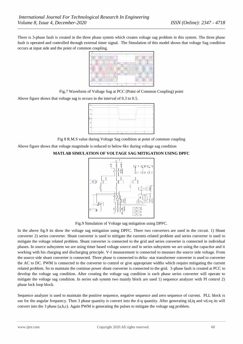
MATLAB SIMULATION OF VOLTAGE SAG MITIGATION USING DPFC
Fig.9 Simulation of Voltage sag mitigation using DPFC.
In the above fig.9 its show the voltage sag mitigation using DPFC. There two converters are used in the circuit. 1) Shunt
converter 2) series converter. Shunt converter is used to mitigate the currents related problem and series converter is used to
mitigate the voltage related problem. Shunt converter is connected to the grid and series converter is connected in individual
phases. In source subsystem we are using timer based voltage source and in series subsystem we are using the capacitor and it
working with his charging and discharging principle. V-I measurement is connected to measure the source side voltage. From
the source side shunt converter is connected. Three phase is connected to delta- star transformer converter is used to converter
the AC to DC. PWM is connected to the converter to control or give appropriate widths which require mitigating the current
related problem. So to maintain the continue power shunt converter is connected to the grid. 3-phase fault is created at PCC to
develop the voltage sag condition. After creating the voltage sag condition is each phase series converter will operate to
mitigate the voltage sag condition. In series sub system two mainly block are used 1) sequence analyzer with PI control 2)
phase lock loop block.
Sequence analyzer is used to maintain the positive sequence, negative sequence and zero sequence of current. PLL block is
use for the angular frequency. Then 3 phase quantity is convert into the d-q quantity. After generating id,iq and vd,vq its will
convert into the 3 phase (a,b,c). Again PWM is generating the pulses to mitigate the voltage sag problem.

International Journal For Technological Research In Engineering
Volume 8, Issue 4, December-2020 ISSN (Online): 2347 - 4718
www.ijtre.com Copyright 2020.All rights reserved. 61
Fig 10 Series Converter Subsystem
Fig.11 Shunt Converter Subsystem
PLL LOOP CONTROL (Phase Locked Loop control)
Here phase detector will compare input frequency and feedback frequency and after that it will generate Ver (error voltage)
which is DC voltage that DC voltage goes in to low pass filter so LPF removes high frequency noise and produces steady DC
level.
That steady DC voltage level pass through voltage controlled oscillator (vco) and so that output frequency directly
proportional to input signal and it try to do equal input and output frequency.
PI CONTROL (Proportional Integral Control)
A PI controller which continuously calculates an error value as the difference between a desired set point (sp) and a measured
process variable (pv) and applies a correction based on proportional and integral terms .The PI controller is the sum of the
instantaneous error values over the time and gives the accumulated offset that should have been corrected previously. The
controller (an analogue/digital circuit, and software), is trying to keep the controlled variable such as temperature, liquid level,
motor velocity, robot joint angle, at a certain value called the set point (sp).
A feedback control system does this by looking at the error (E) signal, which is the difference between where the controlled
variable (called the process variable (PV)) is, and where it should be. Based upon the error signal, the controller decides the
magnitude and the direction of the signal to the output.
Proportional (P) accounts for the present values of the (sp-pv), if the error is the large and positive. Then proportional control
alone will always have an error between the set point and the actual process value because it requires the error to generate the
proportional response if there is no error no response. Integral control (I) accounts for the past values of (sp-pv) and integrates
them over the time to produce the I term and it will add the error value (sp-pv) until it gets the proper output.
Fig.12 PLL loop control

International Journal For Technological Research In Engineering
Volume 8, Issue 4, December-2020 ISSN (Online): 2347 - 4718
www.ijtre.com Copyright 2020.All rights reserved. 62
VOLTAGE WAVEFORM AFTER USING DPFC
Fig 13 Waveform of voltage sag due to fault and source dip in time 0.2 to 1 sec.
Fig 14 Waveform of voltage sag at source side in time 0.5 to 1 sec.
Fig.15 converter injecting voltage in voltage dip
Fig.16 converter injecting voltage in fault sag
Fig.17 constant output voltage after using DPFC in time o.5 to 1 sec.

International Journal For Technological Research In Engineering
Volume 8, Issue 4, December-2020 ISSN (Online): 2347 - 4718
www.ijtre.com Copyright 2020.All rights reserved. 63
Fig.18 Voltage waveform after using DPFC in time 0.5 to 0.8 sec
Here in the simulation we are taking the total time of 1.5 seconds and taking the waveforms of sag and its mitigation with
different time limits and the voltages are pu voltages. First the sag due to fault is in the time between 0.3 to 0.5 seconds and
source voltage dip is in the time of 0.7 to 0.9 seconds. Sag condition is mitigated by DPFC device and we get the constant
voltage output waveform.
MATLAB simulation of voltage swell condition
Fig. 19 MATLAB model for swell problem
Fig 20 Waveform of voltage swell occurs by using circuit
breaker in time 0.6 to 0.7 sec
Fig 21 Waveform of voltage swell by using circuit breaker in time 0.2 to 0.8 sec
Fig.22 Waveform of RMS value of voltage swell
International Journal For Technological Research In Engineering
Volume 8, Issue 4, December-2020 ISSN (Online): 2347 - 4718
www.ijtre.com Copyright 2020.All rights reserved. 64
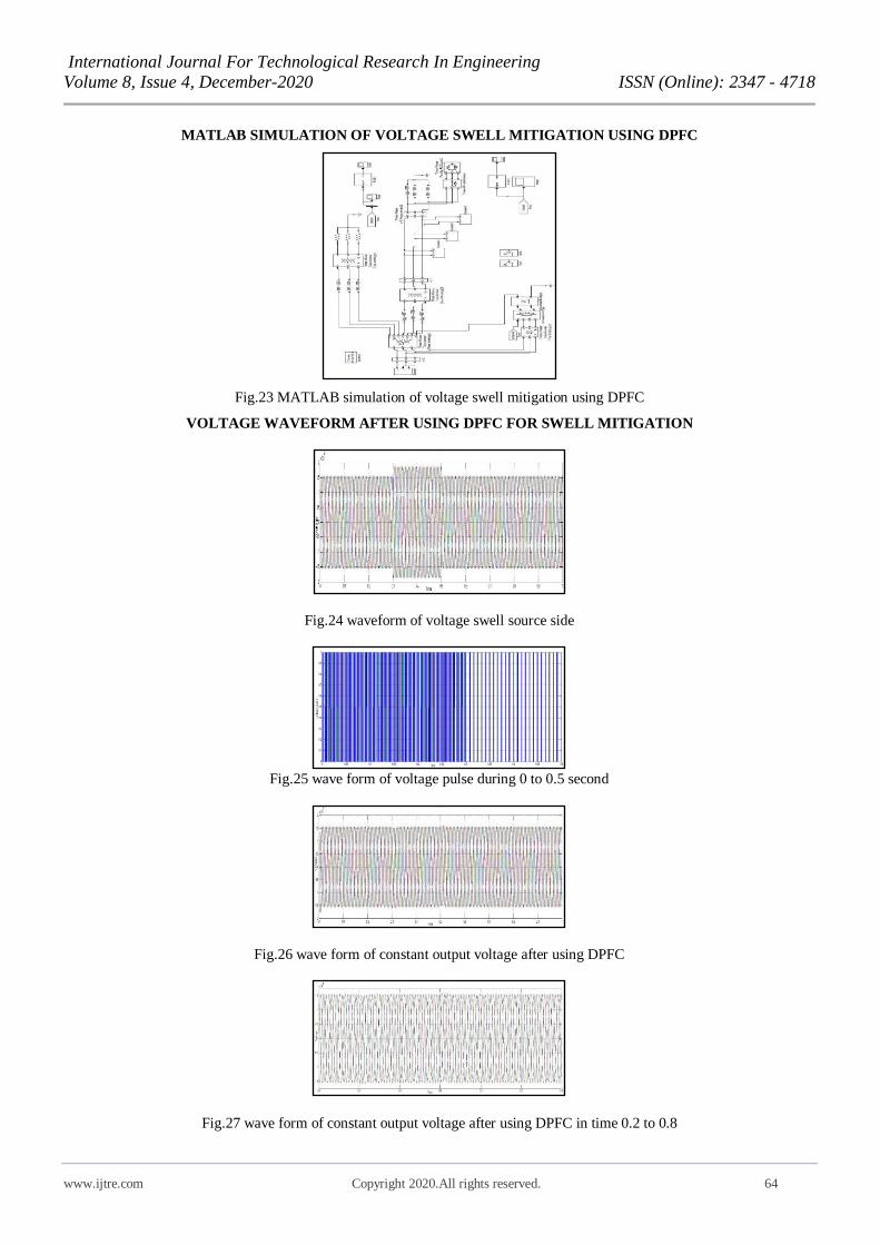
MATLAB SIMULATION OF VOLTAGE SWELL MITIGATION USING DPFC
Fig.23 MATLAB simulation of voltage swell mitigation using DPFC
VOLTAGE WAVEFORM AFTER USING DPFC FOR SWELL MITIGATION
Fig.24 waveform of voltage swell source side
Fig.25 wave form of voltage pulse during 0 to 0.5 second
Fig.26 wave form of constant output voltage after using DPFC
Fig.27 wave form of constant output voltage after using DPFC in time 0.2 to 0.8

International Journal For Technological Research In Engineering
Volume 8, Issue 4, December-2020 ISSN (Online): 2347 - 4718
www.ijtre.com Copyright 2020.All rights reserved. 65
Fig 28 waveform of RMS value of output voltage
MATLAB SIMULATION OF VOLTAGE SAG AND SWELL CONDITION WITH NONLINEAR LOAD
Fig.29 Matlab model for sag and swell condition for nonlinear load
Here we are using a three-phase source and nonlinear load for creation of sag and swell and after that we can see the output
waveform as below for one second of time.
Fig.30 Load side voltage waveform for sag and swell condition for nonlinear load
MATLAB SIMULATION OF VOLTAGE SAG AND SWELL MITIGATION FOR NONLINEAR LOAD USING
DPFC
Fig.31 Matlab model for sag and swell mitigation using DPFC for nonlinear load

International Journal For Technological Research In Engineering
Volume 8, Issue 4, December-2020 ISSN (Online): 2347 - 4718
www.ijtre.com Copyright 2020.All rights reserved. 66
Fig.32 Load side voltage waveform for sag and swell condition after using DPFC for nonlinear load
THEORY OF DPFC FOR INTERCONNECTED MULTI BUS SYSTEM
Fig.33 Three source ten bus system for example
Here we are going to discuss how to put DPFC for our real life interconnected system. Here we are taking ten bus system. If at
any bus, fault is there at that faulty bus we will put DPFC at that bus.
The shunt converter puts at source side and three single phase converter puts in that transmission line. We can put multiple
single-phase converter so that we can maintain the voltage.
5. CONCLUSION
The power quality enhancement of the power transmission systems is a vital issue in power industry. In this study, the
application of DPFC as a new FACTS device in the voltage sag and swell mitigation of a system composed of a three-phase
source connected to a R-L load through the parallel transmission lines is simulated in Matlab/Simulink environment. The
voltage dip is analyzed by implementing a three-phase fault close to the system load. The obtained simulation results show the
voltage sag and voltage swell. We can mitigate the voltage sag and swell problem using DPFC device in this paper and shows
that which device is better for those power quality problems.
REFERENCES
(1) Ahmad Jamshidi, S. Masoud Barakati, and Mohammad Moradi , “Power Quality Improvement and Mitigation Case
Study Using Distributed Power Flow Controller”, Ghahderijani ECE Department, University of Sistan and
Baluchestan, Iran, 2012 IEEE International Symposium on Industrial Electronics.
(2) S.Divya, (PG student) and U. Shyamala, “Power Quality Improvement In Transmission Systems Using DPFC” Dept.
of Electrical and Electronics, M.Kumarasamy college of engineering, Karur, India, 978-1- 4788-7225 -8/15/©2015 IEEE.
(3) Zhihui Yuan, Sjoerd W. H. de Haan, Jan Braham Ferreira, and Dalibor Cvoric, “A FACTS DEVICE: Distributed
Power Flow Controller (DPFC)”, IEEE Transactions on Power Electronics (Volume: 25, Issue: 10, Oct. 2010).
(4) S. Ashok Kumar and N. Vishali M.Tech, “Improvement of Power Quality by Using DPFC”, Department of EEE,
JNTP University Pulivendula, A.P, India, 2016 International Conference on Electrical, Electronics, and Optimization
Techniques (ICEEOT).

International Journal For Technological Research In Engineering
Volume 8, Issue 4, December-2020 ISSN (Online): 2347 - 4718
www.ijtre.com Copyright 2020.All rights reserved. 67
(5) P.Hima Bindu, V.Lavanya, “Voltage sag and swell mitigation using DPFC and improve power quality”, Dept. of
EEE Loads Institute of Engg. And Technology, A.P, INDIA, International Journal of Engineering Research &
Technology (IJERT) Vol. 2 Issue 11, November - 2013.
(6) B.Vijaya Krishna , B.Venkata Prashanth and K.S.R.Anjaneyulu, “Designing of Multilevel DPFC to Improve Power Quality” International Conference on Electrical, Electronics, and Optimization Techniques (ICEEOT) – 2016, 978-1-
4673-9939-5/16/©2016 IEEE
(7) Monika Sharma, Dr. Annapurna Bhargava, Pinky Yadav, “Oscillation Damping with DPFC using Optimization
Techniques”, 2016 International Conference on Micro-Electronics and Telecommunication Engineering, 978-1-5090-
3411-6/16© 2016 IEEE
(8) BUDI SRINIVASARAO, G.SREENIVASAN and SWATHI SHARMA, “MITIGATION OF VOLTAGE SAG FOR
POWER QUALITY IMPROVEMENT USING DPFC SYSTEM”, 978-1-4799-7678-2/15/©2015 IEEE.
(9) S.Divya and U.Shyamala, “Power Quality Improvement In Transmission Systems Using DPFC”, IEEE
SPONSORED 2ND INTERNATIONAL CONFERENCE ON ELECTRONICS AND COMMUNICATION
SYSTEM (ICECS 2015), 978-1- 4788-7225 -8/15/©2015 IEEE.
(10) Akula.N.V.V. Rajasekhar and Mamidi. Naveen Babu, “HARMONICS REDUCTION AND POWER QUALITY
IMPROVEMENT BY USING DPFC”, International Conference on Electrical, Electronics, and Optimization Techniques (ICEEOT) – 2016, 978-1-4673-9939-5/16/©2016 IEEE.
(11) Mr. Kiran A. Patel Palak Hariyaliyan, Mr. Mihir K. Patel, “Simulation of Three Phase Transformer-less Shunt
Active Power Filter for Harmonic Compensation in Grid Connected Applications”, Volume-7, Issue-11, Journal of
Emerging Technologies and Innovative Research (JETIR).
(12) Dr. Swati Sharma, Dr. Devendra Nagal, Mihir Patel, “OPTIMIZATION AND PERFORMANCE ANALYSIS OF
SOLAR PV & CSP SYSTEM”, Volume-10, Issue-8, JOURNAL OF ENGINEERING, COMPUTING &
ARCHITECTURE.