Simulation of a Mortar Launched, Parachute Deployed...
12
Transcript of Simulation of a Mortar Launched, Parachute Deployed...

inedgeare
to betem
is anningpara-try ofreas-ds tolso,
l views type
Downloaded F
Geoffrey Frost1
Mark Costello2
Department of Mechanical Engineering,Oregon State University,
Corvallis, OR 97331
Simulation of a Mortar Launched,Parachute Deployed BattlefieldImaging SystemFlight behavior of a mortar launched, parachute deployed imaging system is examwith particular attention to characterizing the quantity and quality of recorded imadata. Coverage area of the imager, blur due to motion of the imager, and view timeevaluated for different system configurations allowing important design parametersidentified. It is shown that proper tailoring of the dynamic characteristics of the sysgreatly improves gathered image data quantity and quality. Coning of the canisterimportant system characteristic that largely drives total ground coverage. Canister cois influenced in a complex manner by system geometric parameters. Mounting thechute riser to the canister in such a way that the connection is off the axis of symmethe canister is a powerful technique to increase coning of the canister. Likewise, incing riser length also yields increased coning. Increasing spin rate of the canister leaa proportional increase in image blur, which is largest toward the edge of the image. Aincreased canister weight tends to increase the descent rate, which reduces totatime. At the same time, increased descent rate increases the spin rate for crosparachutes, leading to increased image blur.@DOI: 10.1115/1.1789974#
e
n
t
-e
av
mW
is
ah
o
p ofse of
e inon-viorara-and
e.es-odelrast
icsom-In a
tedcantimi-e iniesm-hetheand
ckp-
-
s toe
ofthetor-ord-re-
R
M
T
IntroductionThis paper investigates dynamic modeling and performanc
a mortar launched, parachute deployed imaging system thatvides remote reconnaissance. This system will enable forwscouts to remain out of harms way while providing timely acritical information at the platoon level. The dynamic event cosidered consists of a cross type parachute borne sensor pladeployed from a mortar and the ensuing dynamics as it driftsthe ground. The cross-type parachute and sensor platform aretained within the nose of the mortar until deployment. Deploment occurs at a specified time by an explosive charge that srates the fore and aft sections of the mortar and ejects the seplatform and its attached parachute out of the nose. The crossparachute inflates and decelerates the sensor platform. The splatform consists of a cylinder shaped canister fitted with a caera in its nose and the necessary electronics to transmit imback to a ground station. A schematic of the overall event is giin Fig. 1.
A number of models have been used to evaluate the dynaof parachute and load systems in the atmosphere. White and@1# considered the stability of a parachute using a 5-degreefreedom model. They established that a large longitudinal disbance on most parachutes results in large pitching motwhereas a large lateral~out of the glide plane! disturbance causelarge angle vertical coning motion. In a later study, Wolf@2# con-sidered the stability of a parachute connected to a load usin10-degree-of-freedom representation. Wolf established that stity is reduced as riser length is increased or parachute weigincreased. It was also noted that stability of a parachute isproved by increasing axial and normal aerodynamic force. Shpand Levin@3# supported this notion in a parametric investigati
1Graduate Research Assistant, Department of Mechanical Engineering, OFellow.
2Associate Professor, Department of Mechanical Engineering, Member ASThe authors would like to thank Mr. Charles Hainz for his assistance in gatheringsample images presented in the paper.
Contributed by the Dynamic Systems, Measurement, and Control Division ofHEAMERICAN SOCIETY OF MECHANICAL ENGINEERS for publication in the ASMEJOURNAL OF DYNAMIC SYSTEMS, MEASUREMENT, AND CONTROL. Manuscriptreceived by the ASME Dynamic Systems and Control Division November 6, 20Associate Editor: J. Tu.
Journal of Dynamic Systems, Measurement, and ControlCopyright © 2
rom: http://dynamicsystems.asmedigitalcollection.asme.org/ on 07/23/201
ofpro-arddn-formto
con-y-epa-nsortypensorm-gesen
icsolf
-of-tur-on,
g abil-t isim-undn
they conducted on the aerodynamic characteristics of a groucross-type parachutes. Their measurements showed an increaup to 50% in the axial force due to spin, followed by a decreasthe longitudinal stability, leading to an increase in coning motiduring descent. Doherr and Schilling@4# reported on the development of a 9-degree-of-freedom dynamic model to predict behaof a parachute connected to a load. They found that rotating pchute systems are very sensitive to atmospheric disturbancesresult in oscillations of the load with considerable amplitudThey also found that a dynamic model with more than 6-degreof-freedom are necessary with an appropriate mathematical mof the joint between the load and the parachute. This is in contto Neustadt, Ericksen, Guiteras, and Larrivee@5# who used a6-degree-of-freedom mathematical analysis to study the dynamof a payload-parachute system in which they concluded that cputer results were in excellent agreement with test results.study conducted by Shpund and Levin@6#, the effect of decreasingcanopy to payload diameter ratio was experimentally investigaon cross-type rotating parachutes. The results showed a signifidecrease in drag coefficient with decreasing diameter ratio. Slarly, an increase of the forebody’s diameter yields a decreasspin. Diameter ratio also affects static stability. This effect varbetween improved stability for short cord configurations, comonly used for submunitions, to a reduction in stability when tcords are sufficiently longer. The investigation also includedeffects of the canopy aspect ratio, different support systems,the attachment diameter of the cords to the payload.
The use of image data and algorithms to identify and traobjects is also fairly well developed. Algorithms have been aplied to a host of different applications@7#. Example applicationsinclude missile guidance@8,9#, autonomous navigation of highway vehicles@10–13#, stellar tracking@14#, ship motion@15#, ro-bot guidance@16–18#, manufacturing@19#, and solid modeling@20#. The usual procedure is to construct separate algorithmidentify where a particular target is within the field of view of thcamera and subsequently rotate the camera within the fieldregard so that the target object remains in the field of view ofcamera for future recorded frames. Consideration of image distion caused by camera and target dynamics during image recing is not normally considered. In the application of remote
ISE
E.the
03.
SEPTEMBER 2004, Vol. 126 Õ 583004 by ASME
4 Terms of Use: http://asme.org/terms

u
f
w
s
le
t
s
ecan
om-
metheare
is,
tan-d:
ch
elds
ings
Downloaded F
connaissance at the platoon level it is necessary to obtainimage of the target that can be distinguished by a human forwobserver@21–24#.
Projectile and parachute-payload dynamics have not previobeen integrated with optical system metrics in a simple mannepredict image quality based on simulated flight dynamics ocomplete imaging system. Also, most previous efforts describparachute-payload simulations do not consider deployment ofparachute-payload system. This paper simulates a parachpayload imaging system that is deployed from a discharged mtar. A standard 6-degree-of-freedom model is used for the inmortar. Once the mortar separates and the parachute payloadtem is deployed, a twelve degree-of-freedom model is usedpredict the parachute-payload imaging system’s trajectory, asas six degrees-of-freedom to model the translational motion ofseparated mortar round bodies. The work reported here deveformulas to estimate picture quality@25# using dynamic data re-corded from a mortar launched, parachute deployed imagingtem. The formulas are based on the state of the sensor platforthe time of imaging and individual camera parameters, suchfocal length, shutter speed, pixel size, and CCD size. The scaan image, the amount of blur caused from motion of the camthe ground area covered in each image and total ground areaered in a scenario are estimated to aid in the design of a real-mortar launched imaging system. The influence of important stem parameters, such as, canister to parachute attachment pmass of the canister, center of gravity placement and camspecifications is documented.
Simulation DescriptionThe intact mortar, the canister, and the parachute are mod
as rigid bodies with six degrees of freedom each. The degreefreedom for each body include three position components ofmass center of the body as well as three Euler orientation anof the body. A riser, modeled as a spring and damper, connectscanister and parachute. A diagram of the mortar and imagingtem and the reference frames used to describe the systemshown in Fig. 2. It is important to note that a nonconventionalof unit vector directions for the bodies is employed. In particulthe axis of symmetry for the bodies is thek unit vector, as op-posed to the more conventional definition ofi. The formation ofthe equations describing each rigid body is the same and theeral formulas are given for a rigid body with six degrees of fre
Fig. 1 Mortar launched, parachute deployed battlefield imag-ing system schematic
584 Õ Vol. 126, SEPTEMBER 2004
rom: http://dynamicsystems.asmedigitalcollection.asme.org/ on 07/23/201
anard
slyr to
aingtheute-or-
tactsys-toell
thelops
ys-m atas,
e ofra,cov-imeys-oint,era
eleds oftheglestheys-s is
setar,
gen-e-
dom. The subscript,B, is used to denote the body frame. Thformulas for the intact mortar, the canister, and the parachutebe obtained by replacing the subscript,B, with the subscripts,M,C, andP, respectively.
The three translational degrees of freedom are the three cponents of the body mass center position vector,
rO→B5xBI I1yBJI1zBK I . (1)
A sequence of rotations from the inertial frame to the body frais defined by a set of body-fixed rotations that are ordered inconventional manner. The three rotational degrees of freedomthe Euler roll angle (fB), pitch angle (uB), and yaw angle (cB).The transformation from each body frame to the inertial frame
H I I
JI
K I
J 5F cuBccB
sfBsuB
ccB2cfB
scBcfB
suBccB
1sfBscB
cuBscB
sfBsuB
scB1cfB
ccBcfB
suBscB
2sfBccB
2suBsfB
cuBcfB
cuB
G3H IB
JB
KB
J 5@TB#H IB
JB
KB
J (2)
In the above equations and the equations shown below, the sdard shorthand notation for trigonometric functions is usesin(a)[sa , cos(a)[ca , tan(a)[ta .
The mass center velocity vector of the body is defined in eaof the reference frames discussed above,
VB/I5uBIB1vBJB1wBKB5 xBI1 yBJI1 zBK I (3)
as is the angular velocity vector of the body
vB/I5pIB1qJB1rKB . (4)
Applying the transformation given in Eq.~2! to the mass centervelocity components expressed in the body reference frame yi
H xB
yB
zB
J 5@TB#H uB
vB
wB
J (5)
Equating the projectile angular velocity vectors described usbody frame components and using Euler angle rates generate
Fig. 2 Mortar and imaging system reference frames
Transactions of the ASME
4 Terms of Use: http://asme.org/terms
t
o
e
oa
cmp
c
i
sterfterod-
ctingration
hasdies,
ed
dies.rom
rom
ister
ess
s be-ned
atingara-ordslin-
fla-hasngchutee hasy-
can-rvalr
-ired.andnd.
isesion
sersion
Downloaded F
H fB
uB
cB
J 5F 1 sfBtuB
cfBtuB
0 cfB2sfB
0 sfB/c0B
cfB/cuB
G H pB
qB
r B
J (6)
The kinetic differential equations are derived by consideringforces and moments associated with each individual body. Eqtion ~7! gives the translational kinetic differential equation feach body,
mBaB/I5FB (7)
where,
aB/I5BdVB/I
dt1vB/I3VB/I (8)
The rotational kinetic equation of motion for each body is givby
IdHB/I
dt5MB (9)
When expressed in component form the translational and rtional dynamic equations for each rigid body, including the intmortar, the parachute, and the payload take the structure showEqs.~10–11!.
H uB
vB
wB
J 5H XB /mB
YB /mB
ZB /mB
J 2F 0 2r B qB
r 0 2pB
2qB pB 0G H uB
vB
wB
J (10)
H pB
qB
r B
J 5@ I B#21F H LB
MB
NB
J 2F 0 2r B qB
r B 0 2pB
2qB pB 0G @ I B#H pB
qB
r B
J G(11)
During the initial phase of flight when the mortar round is intathe mass, mass center location, and inertial properties of thetar are based on the composite body. The intact mortar has apload contributions from weight and body aerodynamic forces,
H XM
YM
ZM
J 5H XW
YW
ZW
J 1H XA
YA
ZA
J (12)
while the canister and parachute both have applied load contrtions from weight, body aerodynamic forces, separation forand the riser connection force. Since the equations of motionexpressed in the body frame, all forces are expressed in thevidual body frames.
H XC
YC
ZC
J 5H XP
YP
ZP
J 5H XW
YW
ZW
J 1H XA
YA
ZA
J 1H XS
YS
ZS
J 1H XR
YR
ZR
J (13)
For all bodies, the weight force takes on the following form
H XW
YW
ZW
J 5WH 2su
sfcu
cfcu
J (14)
The aerodynamic force on the intact mortar uses a standard adynamic expansion
H XA
YA
ZA
J 51
2rV2D5
CNA
u
w
CNA
vw
CZ01CZ2
u21v2
w2
6 (15)
Journal of Dynamic Systems, Measurement, and Control
rom: http://dynamicsystems.asmedigitalcollection.asme.org/ on 07/23/201
heua-r
n
ta-ctn in
t,or-lied
ibu-esarendi-
ero-
Prior to mortar separation the motions of the stowed caniand parachute are generated from kinematic relationships. Amortar separation, the fore and aft sections of the mortar are meled as point masses with 3-degrees-of-freedom. The loads aon the separated sections are weight, aerodynamic, and sepaforces.
After the separation force has expired and the parachuteopened, the canister and parachute are modeled as rigid boeach with 6 degrees of freedom.
Equation~16! provides the aerodynamic force expression usfor both the parachute and payload.
H XA
YA
ZA
J 52p
2rV2AH CNu/V
CNv/VCT
J (16)
where
V5Au21v21w2 (17)
The aerodynamic forces act at the center of pressure of the boThe aerodynamic coefficients for the parachute are obtained fstandard wind tunnel tests and substituted directly into Eq.~16!.The aerodynamic coefficients for the canister are obtained fpublished literature@4#.
The above aerodynamic forces are not exerted on the canuntil after the expulsion charge has elapsed@26,27#. Because ofthe complexity of canopy inflation, a simple quasi-static procbased on the parachute’s drag reference area is employed@28#.The mortar separates and the parachute deployment procesgins after the expulsion charge has expired. Drag on the unopeparachute is substantially higher than the canister thus separthe two bodies. Canopy stretch occurs after the canister and pchute have separated a distance equal to the length of the cplus the riser length. Drag area of the parachute is increasedearly for approximately 0.3 s during this phase. Full canopy intion occurs at a much greater linear rate until the canopyreached its full diameter. During canopy inflation the roll inducimoment of the parachute is assumed to be zero and the parahas a spin rate equal to that of the canister. Once the parachutreached its full diameter, Eq.~16! is used to generate the aerodnamic forces on the parachute.
To separate the mortar round and eject the parachute andister, an equal and opposite force acting over a short time inteis exerted on the bodies. Equation~18! provides an expression fothis force during separation.
H XS
YS
ZS
J 56PSAH nX
nY
nZ
J (18)
The pressure,PS , from Eq. ~18! is given as a 6th order polynomial when active and is equal to zero after the charge has expThe forces are positive for the nose section of the roundnegative for the parachute, canister and aft section of the rou
The riser force is caused by the elasticity of its material anddirected parallel to the riser line. The riser flexibility generatresistive stiffness and damping forces proportional to its extensand extension rate. Using the position and velocity of the riattachment points, vectors describing the extension and extenrate can be formed.
DL5A~xC2xP!21~yC2yP!21~zC2zP!2 (19)
SEPTEMBER 2004, Vol. 126 Õ 585
4 Terms of Use: http://asme.org/terms
Downloaded F
DV5~~xC2xP!~ xC2 xP!1~yC2yP!~ yC2 yP!1~zC2zP!~ zC2 zP!!
DL(20)
s
y
y
n
e
o
ft
i
by a
de-era
agesob-
tionunddamesictheelof a
is
neintq.
Once Eq.~20! is formed, Eq.~21! is used to determine the magnitude of the riser force.
FR5H k~DL2L !1cDV, DL2L>0
0, DL2L<0J (21)
The second condition in Eq.~21! stipulates that when the riser islack, no force is transmitted to the attachment points. The elariser force expressed in inertial coordinates is shown in Eq.~22!.
H XR
YR
ZR
J 5FR
DL H xC2xP
yC2yP
zC2zP
J (22)
The total applied moments on the intact mortar contain conbutions from steady body aerodynamics, and unsteady body adynamics
H LM
M M
NM
J 5H LSA
MSA
NSA
J 1H LUA
MUA
NUA
J (23)
while the total applied moments on the canister about its mcenter contain contributions from the steady air loads, unsteadloads, and the riser connection force.
H LC
MC
NC
J 5H LSA
MSA
NSA
J 1H LUA
MUA
NUA
J 1H LR
MR
NR
J (24)
The total applied moments on the parachute take on the sform as that of the canister. The mortar considered in this analis fin stabilized with a relatively low roll rate, so Magnus effecare not included in the aerodynamic expansion. The steady baerodynamic moment is computed by a cross product betweedistance vector from the center of gravity to the center of pressand the steady body aerodynamic force vector above. Thesteady body aerodynamic moment provides a damping sourcthe angular motion of all the bodies and is given below.
H LUA
MUA
NUA
J 51
2rV2D5
pDCMQ
2VqDCMQ
2V
CLDD1rDCLP
2V
6 (25)
For the parachute and payload, the moment due to the riser fis computed with a cross product between the distance vefrom the mass center of the body to the location of the specforce. Note, for the parachute the center of pressure locationall aerodynamic coefficients depend on the angle of attack, wfor the intact mortar the center of pressure and all aerodynacoefficients depend on the Mach number of the mass center omortar. Mach number is computed at the center of gravity ofmortar. For the payload, the center of pressure is fixed atgeometric center. The aerodynamic angle of attack for the canand parachute are calculated as shown in Eq.~26!.
a5cos21S w
VD (26)
Air density for the mortar, canister, and parachute is compuusing the center of gravity position of the appropriate body
586 Õ Vol. 126, SEPTEMBER 2004
rom: http://dynamicsystems.asmedigitalcollection.asme.org/ on 07/23/201
-
stic
tri-ero-
assair
amesis
tsodythe
ureun-for
rcectorificandhilemicthehethester
tedin
concert with the standard atmosphere@26#. Computationally, allaerodynamic coefficients and centers of pressure are obtainedtable look-up scheme using linear interpolation.
System Performance MetricsProper design of a real-time mortar launched parachute
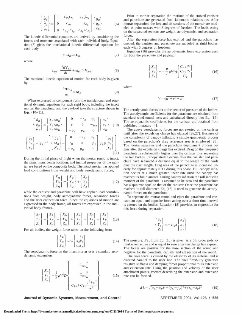
ployed imaging system requires that the canister mounted camrecord images of a target area and be able to transmit those imto a ground station where they can be identified by a humanserver. In order to evaluate image quality, the position and moof the image plane of the camera must be known in the groreference frame~see Fig. 3!. The position of the image plane anthe camera focal point with respect to the canister reference frlocated on the canister’s center of gravity is known from the bacamera configuration. The center of gravity of the canister ininertial ground frame is known from the flight dynamic moddescribed above. The position in the ground reference framepoint on the image plane and the focal point of the cameracalculated using the following kinematic relationship.
H xi
yi
zi
J 5H xc
yc
zc
J1F cucc sfsucc2cfsc cfsucc1sfsc
cusc sfsusc1cfcc cfsusc2sfcc
2su sfcu cfcu
Gc
H r x
r y
r z
Ji
(27)
With the focal point and the point of interest on the image plaknown in the ground reference frame, the projection of the poin the ground plane is determined using similar triangles in E~28! ~see Fig. 3!. The variable,zg , is the height of the groundsurface above sea level and is assumed to be 10 m.
Fig. 3 System metrics
Transactions of the ASME
4 Terms of Use: http://asme.org/terms
eotu
amre
g
a
o
r
nhh
-
m
t
dta
cn
ble,ometo
outin. 6
Downloaded F
H xg
yg
zg
J 55xf1
~zg2zf !~xi2xf !
~zi2zf !
yf1~zg2zf !~yi2yf !
~zi2zf !
zg
6 (28)
A polygon representing the image captured by the camera istained by projecting the four corners of the image plane ontoground plane. Thus, the amount of ground area captured byimage is determined by calculating the area of the projected pgon. Total area of coverage for an individual scenario is demined by using an algorithm that sums the ground area captby each image and subtracts areas of image overlap.
A determining factor in image clarity is resolution. The camemust be within a prescribed distance of the ground so that taeffects are visible on the recorded images. As the camera nearground, the ground area in view decreases and the picture clincreases, therefore the rate of descent is important to deterhow many useful images can be transmitted at the appropdistance from the ground with an acceptable resolution. The rlution, or amount of detail in a frame, is a function of the sizepixels, the focal length of the imager, and the distance fromground plane to the image plane. Pixel sizes and focal lenvary for different cameras. The size of the area mapped toindividual pixel, or pixel scale, is determined using Eq.~29!.
PX5PL~zg2zf !
~zi2zf !(29)
Buildings and roads can be distinguished in an image of an ursetting where the area captured by each pixel measures 232 m onthe ground. Vehicles can be recognized in an image capturedaltitude where each pixel measures 0.530.5 m on the ground.More details on image resolution can be found in Ref.@29#.
Another factor concerning picture clarity is image smearinImages from cameras with high exposure rates can becsmeared, or blurred, if the canister’s roll rate is too high orlateral oscillations are too drastic. Therefore, the canister rolland lateral oscillations must be limited to avoid image smearfor cameras with high exposure times. Pixel blur is defined asnumber of pixels a point in the ground plane moves through isingle exposure time. Pixel blur is determined by multiplying tvelocity of the projection of a point in the ground plane by texposure time, or shutter speed of the camera, and dividing bypixel scale. Differentiating Eq.~28!, and determining the magnitude yields the velocity of a projected point in the ground plashown in Eq.~30!.
Vg5Axg21 yg
2 (30)
The pixel blur function is shown in Eq.~31!.
PB5Vgtss
PX(31)
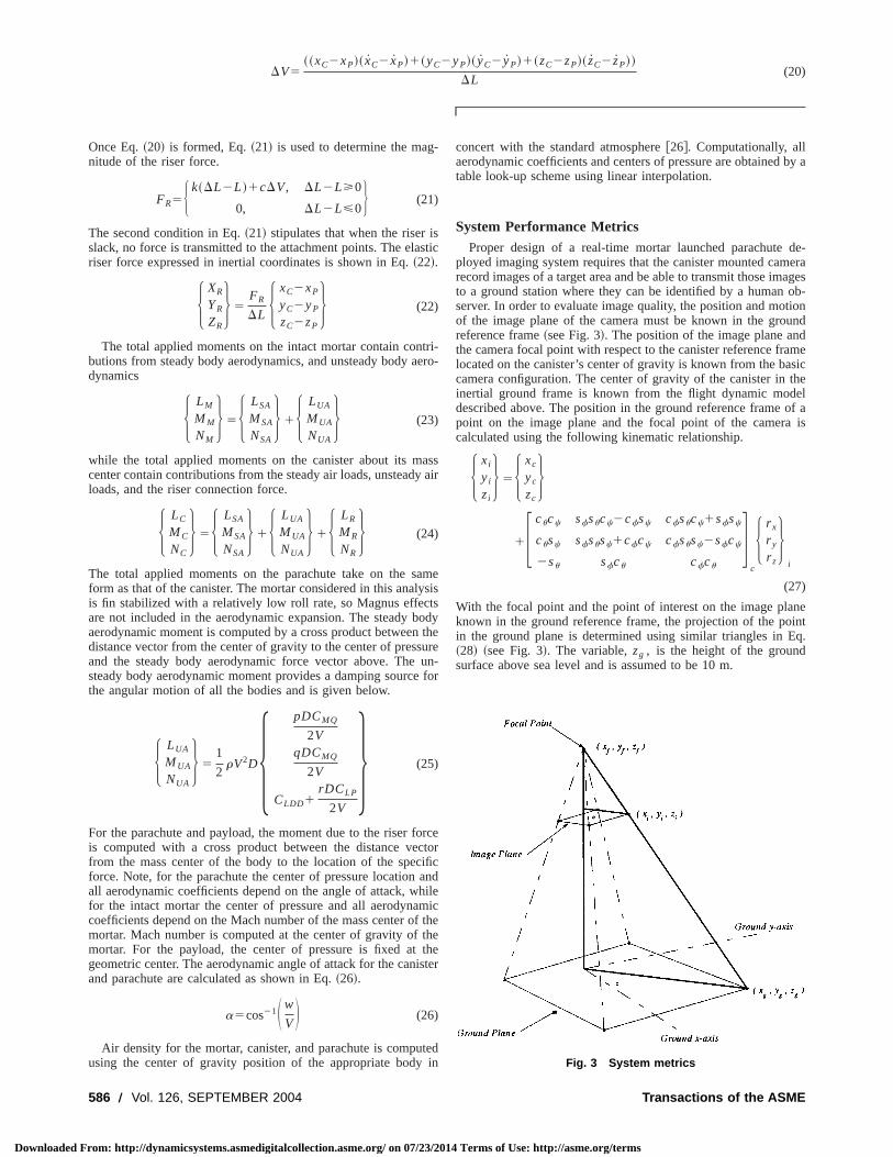
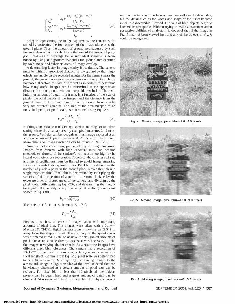
Figures 4–6 show a series of images taken with increasamounts of pixel blur. The images were taken with a SonyMavica MVCFD91 digital camera from a moving car 3.048away from the display panel. The accuracy of the speedomwas estimated at64.0 kph. To achieve the designated amountspixel blur at reasonable driving speeds, it was necessary tothe images at varying shutter speeds. As a result the imagesdifferent pixel blur tolerances. The camera has a resolution10243768 pixels with a pixel size of 6.5mm and was set at afocal length of 5.2 mm. From Eq.~29!, pixel scale was determineto be 3.84 mm/pixel. By comparing the moving images toalmost still image in Fig. 4 an idea of the level of detail that cbe visually discerned at a certain amount of pixel blur canrealized. For pixel blur of less than 10 pixels all the objepresent can be determined and a great amount of detail caobserved. At a range of 10–30 pixels of blur the objects pres
Journal of Dynamic Systems, Measurement, and Control
rom: http://dynamicsystems.asmedigitalcollection.asme.org/ on 07/23/201
ob-theachly-
er-red
rargets therityine
iateso-ofthethsan
ban
t an
g.me
itsateingthe
aeethe
ne
ing—
eterofakehave
of
hen
bets
beent
such as the tank and the beaver head are still readily detectabut the detail such as the words and shape of the turret becmuch less discernible. Beyond 30 pixels of blur, objects beginbecome imperceptible. Without trying to make a statement abperception abilities of analysts it is doubtful that if the imageFig. 4 had not been viewed first that any of the objects in Figcould be recognized.
Fig. 4 Moving image, pixel blur Ä2.0Á0.5 pixels
Fig. 5 Moving image, pixel blur Ä10.0Á3.0 pixels
Fig. 6 Moving image, pixel blur Ä40Á5.0 pixels
SEPTEMBER 2004, Vol. 126 Õ 587
4 Terms of Use: http://asme.org/terms
5
Downloaded Fro
n
d
tay
ud
t
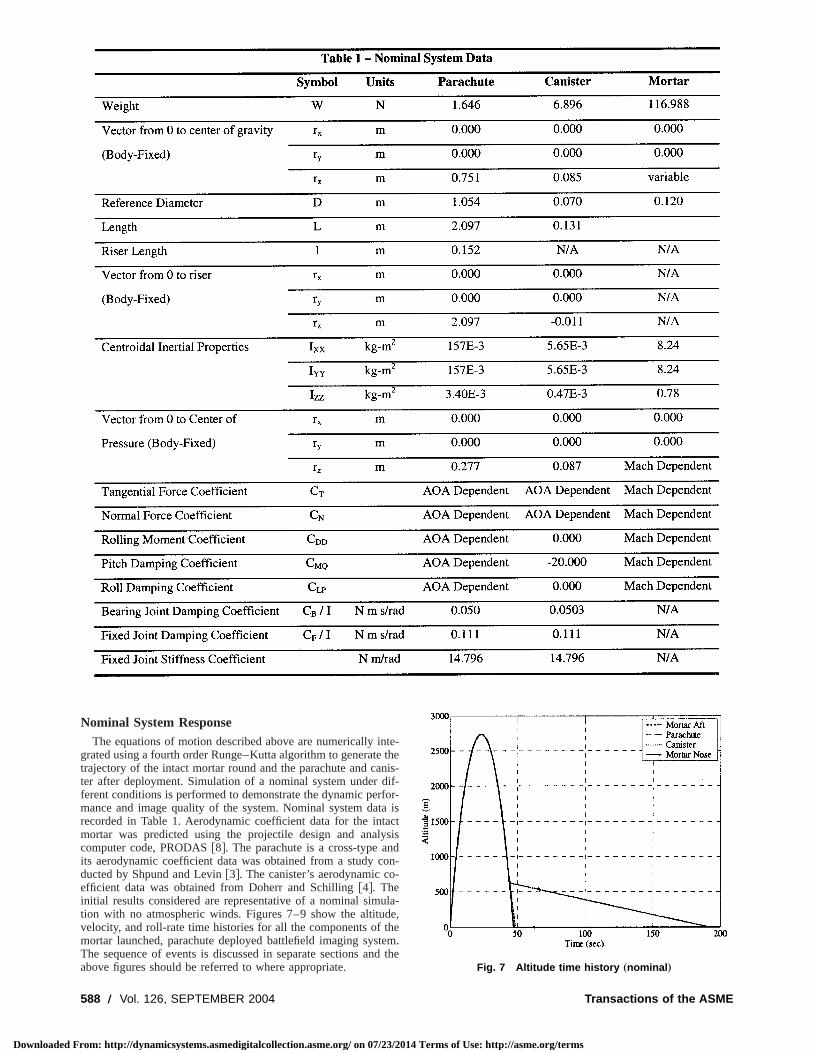
Nominal System ResponseThe equations of motion described above are numerically i
grated using a fourth order Runge–Kutta algorithm to generatetrajectory of the intact mortar round and the parachute and cater after deployment. Simulation of a nominal system underferent conditions is performed to demonstrate the dynamic permance and image quality of the system. Nominal system darecorded in Table 1. Aerodynamic coefficient data for the intmortar was predicted using the projectile design and analcomputer code, PRODAS@8#. The parachute is a cross-type anits aerodynamic coefficient data was obtained from a study cducted by Shpund and Levin@3#. The canister’s aerodynamic coefficient data was obtained from Doherr and Schilling@4#. Theinitial results considered are representative of a nominal simtion with no atmospheric winds. Figures 7–9 show the altituvelocity, and roll-rate time histories for all the components of tmortar launched, parachute deployed battlefield imaging sysThe sequence of events is discussed in separate sections anabove figures should be referred to where appropriate.
88 Õ Vol. 126, SEPTEMBER 2004
m: http://dynamicsystems.asmedigitalcollection.asme.org/ on 07/23/201
te-thenis-if-
for-a isctsisdon--
la-e,
heem.d the
Fig. 7 Altitude time history „nominal …
Transactions of the ASME
4 Terms of Use: http://asme.org/terms
t
za
o
lp
epa-ordshuteThisck
o thera-othm.in-
eionof
centnseadytheas a
, theisterw-due
sesthee ofonalehute
ragntlyteate oftheionhante is
nto
r istheex-e of
Downloaded F
Nominal Scenario. In the nominal scenario, the mortar exithe muzzle with a velocity of 261 m/s at a pitch angle of 70 dfrom horizontal. The mortar separates and the parachute andister are deployed 43.75 s into the flight. The camera is activa50 s into flight. The trajectories of the various components cocide during the intact mortar flight phase. The trajectories diveat the point of mortar separation.
Mortar Flight. The intact mortar orientation is stable antypical for this type of round. The intact mortar leaves the muzat its initial velocity and slows to a velocity of roughly 76 m/sit reaches its apex approximately 23 s into its flight. The morpitches over and accelerates towards its steady state drop velIt continues to pitch down to an angle of approximately270 degfrom horizontal and travels downrange approximately 3380 mwhich point the mortar separates and the imaging system ispelled. The mortar has slight fin cant, generating roll, and causthe system to deviate approximately 35 m laterally. After sepation the nose and aft components continue to travel down rauntil they impact the ground.
Separation. At 43.75 s the expulsion charge is detonated athe force, acting in equal and opposite directions, acceleratesnose of the mortar and decelerates the aft mortar section, pchute, and canister. The nose and the aft mortar section accetoward their steady state drop velocities and the parachute o
Fig. 8 Body velocity time history „nominal …
Fig. 9 Roll rate time history „nominal …
Journal of Dynamic Systems, Measurement, and Control
rom: http://dynamicsystems.asmedigitalcollection.asme.org/ on 07/23/201
segcan-tedin-rge
dlestarcity.
atex-ingra-nge
ndthe
ara-erateens
and further decelerates the canister. The parachute initially srates from the canister a distance equal to the length of the cplus the riser length. When it reaches this distance the paracopens and the sudden increase in drag stretches the riser.stretch results in a 913 N load in the riser. Once this initial shodamps, the force in the riser becomes steady at a load equal tweight of the canister, approximately 6.8 N. The drag of the pachute slows the forward motion of the canister and they bdescend almost vertically at a range of approximately 3390The lateral motion of the canister and parachute is quickly dimished by parachute drag.
Parachute and Canister Flight. Cross-type parachutes ardesigned to rotate to increase vertical axial force. This rotatdecreases longitudinal stability, which explains the tendencythis type of parachute to experience coning motion during des@3#. This coning motion is responsible for the notable oscillatioafter inflation that gradually lessen as the system reaches ststate. The nominal system incorporates a fixed joint to attachcanister to the parachute riser, thus the parachute cords actrotational spring and damper. As the parachute generates rollcords twist causing the canister to spin. The parachute and cansystem’s drop velocity stabilizes at approximately 4.3 m/s. Hoever, there is a very slight decrease in the descent rate. This isto the parachute’s slightly increasing roll rate, which increavertical axial force. It can be seen in Fig. 9 that the spin ofmortar is imparted to the canister and the parachute at the timseparation. The spin rate of a cross-type parachute is proportito the square of the forward velocity. The initial velocity of thparachute as it exits the round is such that it causes the paracto promptly spin up once it opens. However, due to the high dof the parachute, its velocity decreases rapidly, and consequeits roll rate damps quickly. Due to cord twist canister roll raincreases as the parachute spins up and oscillates about the rthe parachute until it damps around 110 s. Angles of attack ofparachute and canister shown in Fig. 10 exhibit coning motmentioned earlier. Angle of attack of the canister is greater tthat of the parachute because coning motion of the parachuamplified by the lever action of the parachute cord length.
Camera Performance. After the camera is turned on at aaltitude of 600 m, it remains aloft and is consequently ablerecord images for approximately 141 s~Fig. 7!. The imaging rateused for this simulation is 15 frames/s. Therefore, the imageable to record approximately 2115 images before it impactsground. Note that imaging rate should not be confused withposure time. Imaging rate takes into account transmission tim
Fig. 10 Canister and parachute angle of attack time history„nominal …
SEPTEMBER 2004, Vol. 126 Õ 589
4 Terms of Use: http://asme.org/terms
w
faueie
e
f
e
ir
hut
ss
pc
a
r
ialuterom. Inin-ring
fter
wer
ion,t theared
erturedthecentcap-
f thespin
Downloaded F
the captured image, and recording time as well. Camerashigher resolutions, or more pixels per CCD may improve the quity of an image, but they also result in more data that mustrecorded and transmitted, thus resulting in lower imaging rate
In the following figures demonstrating image quality of a sytem, data is reported for an image point located at the center oimage plane and an image point at one corner of the image plThese points were chosen to exhibit the difference in image qity between the center and the edges of the image. Becausmotion of the canister is such that all corner points exhibit simtrends it is only necessary to report a single corner point to donstrate edge image quality. During a nominal flight the imageable to capture a total of 919,000 m2 of ground area. However, thresolution at which the area is captured varies over the duratiothe flight. Figure 11 shows pixel scale versus the amountground area in each image for an image point located at the ceof the image plane and an image point located at the corner oimage plane. For example, the first image captured in the nomscenario records an area of approximately 590,000 m2 with a reso-lution of 0.46 m/pixel. At this resolution objects such as a cwould be discernible. Resolution improves linearly as the camnears the ground, however a smaller amount of area is captureach image. Note that approximately 65% of the total ground acaptured during the flight is gained in the first image, indicatthat of the 2115 images taken, there is a great amount of oveBefore an image can be considered discernible by an analystclarity of the image must be evaluated. Figure 12 shows pixel bfor a shutter speed of 1 ms versus camera height for the nomsystem scenario. Because the camera is spinning the motion oedge points is greater than those at the center resulting in mpixel blur. It can be seen in Fig. 12 that rotational vibration of tcamera due to cord twist shown in Fig. 9 results in large flucttions of pixel blur at the edges of the image, however it has lieffect at center of the image. The smaller oscillations in pixel bafter rotational vibration due to cord twist is damped are a reof the coning motion of the system further referred to as canioscillation. Pixel blur is linearly proportional to shutter speed atherefore varying shutter speed changes pixel blur by a protional amount. For example, if the same scenario was conduwith a 10 ms shutter speed the amount of pixel blur would betimes greater and consequently the image would be muchdiscernible.
Joint Type. For this simulation all system parameters weheld at nominal values except for the type of joint used to attthe parachute riser to the canister. Instead of a fixed joint, a rabearing type joint was used. Similar trends were observed fo
Fig. 11 Pixel scale „resolution … versus ground area captured„nominal …
590 Õ Vol. 126, SEPTEMBER 2004
rom: http://dynamicsystems.asmedigitalcollection.asme.org/ on 07/23/201
ithal-bes.s-thene.al-the
larm-
r is
n ofof
nterthe
inal
arerad inreanglap., thelurinalf theoreea-
tlelurultterndor-ted10less
rechdialall
time traces except for roll rate of system components. A radbearing joint does not allow the cords to twist as the parachspins up, therefore the only moment that acts on the canister fthe parachute rotational motion is due to friction in the bearingFig. 13 it can be seen that roll rate of the canister graduallycreases until it reaches that of the parachute. Thus, the beajoint eliminates erratic canister motion present immediately aparachute inflation for a system with a fixed joint~see Fig. 9!. Asa result less blur is present at higher camera altitudes with loresolutions~Fig. 14!.
Parametric TrendsThe effect of canister weight, canister mass center locat
riser length, and riser attachment offset are considered againsimage system metrics defined earlier. These trends are compin Figs. 15–21.
Effect of Canister Weight. The average rate of descent aftthe camera has been activated and the number of images capversus a range of canister weights is shown in Fig. 15. Asweight of the canister is increased the average rate of desincreases and consequently the number of images able to betured decreases. Also, as the rate of descent or axial velocity oparachute increases so does its spin rate, thus increasing the
Fig. 12 Pixel blur „clarity … versus camera height „nominal …
Fig. 13 Roll rate time history „nominal—bearing joint …
Transactions of the ASME
4 Terms of Use: http://asme.org/terms
i
u
rl
idaeu
s
thee ofolu-vi-xedble
dhas
thege.the
ow-de-off
on-sesffecttheav-e ofhethe
ra-fromtlygth.
thehisundute.arikethatch-isteringofav-
JointGher.andard
Downloaded F
rate of the canister. A direct result of this increased spin rate isincrease in the amount of pixel blur near the edges of the imacaptured. Average pixel blur at the edges of the image for a nonal system is approximately 6.6. Increasing the weight of the cister to 71.17 N increases the average pixel blur for a fixed josystem to approximately 19. Initially after parachute inflatiohowever, fixed joint systems exhibit an oscillatory flight behavthat results in pixel blur per canister oscillation varying up torange that is approximately 50% of the average. Oscillatory cister motion for a fixed joint system immediately after parachinflation is not present for a bearing joint system and the amoof blur is less at higher altitudes and lower resolutions. Fobearing joint system pixel blur for a 71.17 N canister is initiaaround 4 and increases to approximately 16 at which pointcanister contacts the ground. The range of pixel blur per canoscillation remains fairly constant for a bearing joint system anless than 2% of the average. The pixel blur for the center impoints as stated before is not greatly affected by the spin ratthe canister and the pixel blur for these points for the individcanister weights more or less are the same for the range of canweights. As stated before, the pixel scale as a function of camheight is not significantly affected by the weight of the canisterthe type of joint used. Heavier canisters result in increasedrates, but decrease the coning motion of the parachute and thuprojected image does not sweep out as large of an area on
Fig. 14 Pixel blur „clarity … versus camera height „nominal—bearing joint …
Fig. 15 Average rate of descent and number of images cap-tured versus canister weight
Journal of Dynamic Systems, Measurement, and Control
rom: http://dynamicsystems.asmedigitalcollection.asme.org/ on 07/23/201
angesmi-an-intn,ora
an-teunt
alythester
isgeof
alistereraorpins thethe
ground. Note that most of the total ground area captured is infirst few images, and for the fixed joint system these images arthe poorest quality because of the excessive blur and low restion. However, for a bearing joint system the amount of blur edent in these first images is less than those captured by a fijoint system and, consequently, a greater amount of identifiaground area coverage is gained.
Effect of Riser Length. Figure 16 shows the total grounarea captured and the average camera tilt after steady statebeen reached versus riser length. Pixel blur at the edge ofimage is significantly greater than that of the center of the imaThis is the case for all the studies conducted and thereforetrends for the center of the image are not discussed in the folling studies. Because wind is not considered and the systemscends vertically the angle of attack and the camera anglevertical or tilt as referred to by aerial photographers can be csidered identical. Increasing riser length effectively increacamera tilt and thus sweeps out larger ground area. A side ethough is that pixel blur vibrates through a greater range ascanister oscillates. This effect is shown in Fig. 17, where theerage edge pixel blur after steady state along with the rangpixel blur per canister oscillation is shown versus riser length. Tincreased riser length amplifies the moment produced aboutcanister center of gravity due to the coning motion of the pachute and thus increases canister oscillations. It is apparentFigs. 16 and 17 that the type of joint used does not significaneffect image performance of the system for increased riser len
Effect of Canister Mass Center Location. In Figs. 18 and19, the mass center of the canister was placed forward ofnominal position in 9.14 mm increments up to 45.72 mm. Tcan be viewed as moving the center of gravity towards the groif the canister were hanging vertically beneath the parachMoving the canister center of gravity forward exhibits a similtrend of increased pixel blur range per canister oscillation lincreasing the riser length. In this case, this is due to the factthe moment arm from the canister center of gravity to the attament point is increased. Therefore, the moment about the cancenter of gravity due to the force in the riser caused by the conmotion of the parachute is amplified causing larger oscillationsthe canister. Figure 18 shows total ground area captured anderage camera tilt versus location of the canister mass center.type has little effect on tilt angle variation with change in Clocation and the two curves appear to lie on top of each otFigure 19 shows average edge pixel blur after steady statepixel blur range per canister oscillation versus change in forwlocation of the canister mass center.
Fig. 16 Total ground area and average camera angle off verti-cal versus riser length
SEPTEMBER 2004, Vol. 126 Õ 591
4 Terms of Use: http://asme.org/terms
ore
t
a
tr
t
ownlur
ingor-uan-de-icagecan-con-Thisestinage
heantheentser
Downloaded F
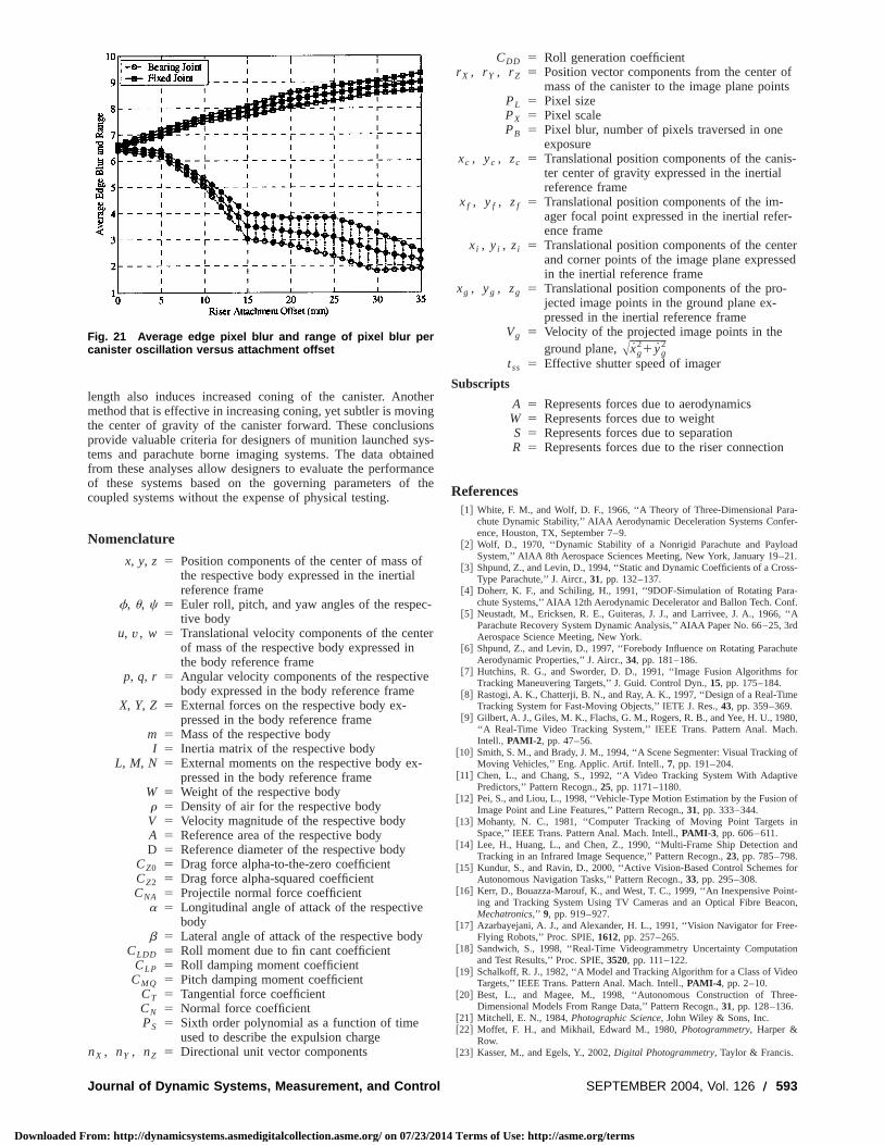
Effect of Riser Attachment Offset. Canister offset is definedas mounting the parachute riser to the canister in such a waythe connection is off the axis of symmetry of the canister. For bthe bearing joint and the fixed joint systems, pixel blur behaviovery erratic until canister spin rate stabilizes at the same ratthe parachute. The range of pixel blur per canister oscillation atends to decay in the course of the flight. The point at which toccurs is considered the steady state of the system for this sImages captured after steady state are higher resolution, howfor a bearing joint, an offset attachment produces more errbehavior than for a center-attached system. Also, an offset fijoint produces greater deviations in pixel blur immediately afparachute inflation than a nominal system. Thus, images recoshortly after parachute inflation are not reliable estimates ofground area captured and image quality is reported for the sysafter it has stabilized. This is considered to have occurred atproximately a height of 500 m. Figure 20 shows total ground acovered and camera angle off vertical for a range of riser attament offsets. Camera tilt is greater for a fixed joint system aconsequently a greater sweep of ground area is captured durindescent than a bearing joint system. Both offset systems capmuch greater ground area than a center-attached system due
Fig. 17 Average pixel blur and range of pixel blur per canisteroscillation versus riser length
Fig. 18 Total ground area and average camera angle off verti-cal versus change in forward placement of the canister centerof gravity
592 Õ Vol. 126, SEPTEMBER 2004
rom: http://dynamicsystems.asmedigitalcollection.asme.org/ on 07/23/201
thatthisof
lsohisudy.evertic
xederdedthetemap-reach-ndg itstureo the
sweeping motion of the canister as it rotates. However, as shin Fig. 21 an offset bearing joint produces less average pixel bat a corner point after steady state is achieved.
ConclusionsSimulation of a mortar launched, parachute deployed, imag
system that integrates dynamic behavior with imaging perfmance has been developed and employed to predict image qtity and quality for an exemplar mortar launched, parachuteployed, imaging system. Through proper tailoring of dynamcharacteristics of the payload and parachute configuration, imperformance can be greatly enhanced. In particular, increasedister weight increases the descent rate of the system, whichsequently increases the spin rate for cross type parachutes.leads to a proportional increase in image blur, which is largtoward the edge of the image. Also, coning of the canistergeneral increases total ground coverage area while causing imblur to increase only slightly. Locating the attachment point of tparachute riser to the canister off the axis of symmetry iseffective technique to increase coning. However, offsettingattachment point causes large initial oscillations after deploymfrom the mortar, which yields unreliable images. Increasing ri
Fig. 19 Average edge pixel blur and range of pixel blur percanister oscillation versus change in forward placement of thecanister center of gravity
Fig. 20 Total ground area and average camera angle off verti-cal versus attachment offset
Transactions of the ASME
4 Terms of Use: http://asme.org/terms
tio
a
f
c
e
e
-
fs
s-
-
ered
a-r-
d21.ss-
a-nf.‘‘A
3rd
ute
or
e
80,h.
of
ve
of
in
nd
for
nt-con,
e-
ion
o
e-
Downloaded F
length also induces increased coning of the canister. Anomethod that is effective in increasing coning, yet subtler is movthe center of gravity of the canister forward. These conclusiprovide valuable criteria for designers of munition launched stems and parachute borne imaging systems. The data obtafrom these analyses allow designers to evaluate the performof these systems based on the governing parameters ofcoupled systems without the expense of physical testing.
Nomenclature
x, y, z 5 Position components of the center of mass othe respective body expressed in the inertialreference frame
f, u, c 5 Euler roll, pitch, and yaw angles of the respetive body
u, v, w 5 Translational velocity components of the centof mass of the respective body expressed inthe body reference frame
p, q, r 5 Angular velocity components of the respectivbody expressed in the body reference frame
X, Y, Z 5 External forces on the respective body ex-pressed in the body reference frame
m 5 Mass of the respective bodyI 5 Inertia matrix of the respective body
L, M, N 5 External moments on the respective body expressed in the body reference frame
W 5 Weight of the respective bodyr 5 Density of air for the respective bodyV 5 Velocity magnitude of the respective bodyA 5 Reference area of the respective bodyD 5 Reference diameter of the respective body
CZ0 5 Drag force alpha-to-the-zero coefficientCZ2 5 Drag force alpha-squared coefficientCNA 5 Projectile normal force coefficient
a 5 Longitudinal angle of attack of the respectivebody
b 5 Lateral angle of attack of the respective bodyCLDD 5 Roll moment due to fin cant coefficient
CLP 5 Roll damping moment coefficientCMQ 5 Pitch damping moment coefficient
CT 5 Tangential force coefficientCN 5 Normal force coefficientPS 5 Sixth order polynomial as a function of time
used to describe the expulsion chargenX , nY , nZ 5 Directional unit vector components
Fig. 21 Average edge pixel blur and range of pixel blur percanister oscillation versus attachment offset
Journal of Dynamic Systems, Measurement, and Control
rom: http://dynamicsystems.asmedigitalcollection.asme.org/ on 07/23/201
herngns
ys-inedncethe
-
r
CDD 5 Roll generation coefficientr X , r Y , r Z 5 Position vector components from the center o
mass of the canister to the image plane pointPL 5 Pixel sizePX 5 Pixel scalePB 5 Pixel blur, number of pixels traversed in one
exposurexc , yc , zc 5 Translational position components of the cani
ter center of gravity expressed in the inertialreference frame
xf , yf , zf 5 Translational position components of the im-ager focal point expressed in the inertial reference frame
xi , yi , zi 5 Translational position components of the centand corner points of the image plane expressin the inertial reference frame
xg , yg , zg 5 Translational position components of the pro-jected image points in the ground plane ex-pressed in the inertial reference frame
Vg 5 Velocity of the projected image points in theground plane,Axg
21 yg2
tss 5 Effective shutter speed of imager
Subscripts
A 5 Represents forces due to aerodynamicsW 5 Represents forces due to weightS 5 Represents forces due to separationR 5 Represents forces due to the riser connection
References@1# White, F. M., and Wolf, D. F., 1966, ‘‘A Theory of Three-Dimensional Par
chute Dynamic Stability,’’ AIAA Aerodynamic Deceleration Systems Confeence, Houston, TX, September 7–9.
@2# Wolf, D., 1970, ‘‘Dynamic Stability of a Nonrigid Parachute and PayloaSystem,’’ AIAA 8th Aerospace Sciences Meeting, New York, January 19–
@3# Shpund, Z., and Levin, D., 1994, ‘‘Static and Dynamic Coefficients of a CroType Parachute,’’ J. Aircr.,31, pp. 132–137.
@4# Doherr, K. F., and Schiling, H., 1991, ‘‘9DOF-Simulation of Rotating Parchute Systems,’’ AIAA 12th Aerodynamic Decelerator and Ballon Tech. Co
@5# Neustadt, M., Ericksen, R. E., Guiteras, J. J., and Larrivee, J. A., 1966,Parachute Recovery System Dynamic Analysis,’’ AIAA Paper No. 66–25,Aerospace Science Meeting, New York.
@6# Shpund, Z., and Levin, D., 1997, ‘‘Forebody Influence on Rotating ParachAerodynamic Properties,’’ J. Aircr.,34, pp. 181–186.
@7# Hutchins, R. G., and Sworder, D. D., 1991, ‘‘Image Fusion Algorithms fTracking Maneuvering Targets,’’ J. Guid. Control Dyn.,15, pp. 175–184.
@8# Rastogi, A. K., Chatterji, B. N., and Ray, A. K., 1997, ‘‘Design of a Real-TimTracking System for Fast-Moving Objects,’’ IETE J. Res.,43, pp. 359–369.
@9# Gilbert, A. J., Giles, M. K., Flachs, G. M., Rogers, R. B., and Yee, H. U., 19‘‘A Real-Time Video Tracking System,’’ IEEE Trans. Pattern Anal. MacIntell., PAMI-2 , pp. 47–56.
@10# Smith, S. M., and Brady, J. M., 1994, ‘‘A Scene Segmenter: Visual TrackingMoving Vehicles,’’ Eng. Applic. Artif. Intell.,7, pp. 191–204.
@11# Chen, L., and Chang, S., 1992, ‘‘A Video Tracking System With AdaptiPredictors,’’ Pattern Recogn.,25, pp. 1171–1180.
@12# Pei, S., and Liou, L., 1998, ‘‘Vehicle-Type Motion Estimation by the FusionImage Point and Line Features,’’ Pattern Recogn.,31, pp. 333–344.
@13# Mohanty, N. C., 1981, ‘‘Computer Tracking of Moving Point TargetsSpace,’’ IEEE Trans. Pattern Anal. Mach. Intell.,PAMI-3 , pp. 606–611.
@14# Lee, H., Huang, L., and Chen, Z., 1990, ‘‘Multi-Frame Ship Detection aTracking in an Infrared Image Sequence,’’ Pattern Recogn.,23, pp. 785–798.
@15# Kundur, S., and Ravin, D., 2000, ‘‘Active Vision-Based Control SchemesAutonomous Navigation Tasks,’’ Pattern Recogn.,33, pp. 295–308.
@16# Kerr, D., Bouazza-Marouf, K., and West, T. C., 1999, ‘‘An Inexpensive Poiing and Tracking System Using TV Cameras and an Optical Fibre BeaMechatronics,’’ 9, pp. 919–927.
@17# Azarbayejani, A. J., and Alexander, H. L., 1991, ‘‘Vision Navigator for FreFlying Robots,’’ Proc. SPIE,1612, pp. 257–265.
@18# Sandwich, S., 1998, ‘‘Real-Time Videogrammetry Uncertainty Computatand Test Results,’’ Proc. SPIE,3520, pp. 111–122.
@19# Schalkoff, R. J., 1982, ‘‘A Model and Tracking Algorithm for a Class of VideTargets,’’ IEEE Trans. Pattern Anal. Mach. Intell.,PAMI-4 , pp. 2–10.
@20# Best, L., and Magee, M., 1998, ‘‘Autonomous Construction of ThreDimensional Models From Range Data,’’ Pattern Recogn.,31, pp. 128–136.
@21# Mitchell, E. N., 1984,Photographic Science, John Wiley & Sons, Inc.@22# Moffet, F. H., and Mikhail, Edward M., 1980,Photogrammetry, Harper &
Row.@23# Kasser, M., and Egels, Y., 2002,Digital Photogrammetry, Taylor & Francis.
SEPTEMBER 2004, Vol. 126 Õ 593
4 Terms of Use: http://asme.org/terms

n
n
2
ine-
nairsnd
Downloaded F
@24# Jensen, J. R., 1996,Introductory Digital Image Processing A Remote SensiPerspective, Prentice–Hall, Inc.
@25# Avery, T. E., and Berlin, G. L., 1985,Fundamentals of Remote Sensing aAirphoto Interpretation, Prentice–Hall, Inc.
@26# Von Mises, R., 1959,Theory of Flight, Dover Publications Inc.@27# PRODAS—Projectile Design and Analysis, Arrow Tech Associates, Inc., 1
Shelburne Road, Suite D-8, Pierson House, South Burlington, VT 0542002.
594 Õ Vol. 126, SEPTEMBER 2004
rom: http://dynamicsystems.asmedigitalcollection.asme.org/ on 07/23/201
g
d
3303,
@28# Wolfe, W. P., and Peterson, C. W., ‘‘Modeling of Parachute Suspension LWrap,’’ AIAA with permission, Sandia National Laboratories, 2001, AIAA2001-2025.
@29# ‘‘MIT Digital Orthophoto Browser,’’Massachusetts Geographical InformatioSystems: Massachusetts Executive Office of Environmental Aff,PlanningISupport Systems Group, M.I.T. Department of Urban Studies aPlanning, 5 February, 1998, http://ortho.mit.edu/nsdi/index.html.
Transactions of the ASME
4 Terms of Use: http://asme.org/terms