
SIMULATION AND ANALYSIS OF THE PROCESS CONTROL …
118
SIMULATION AND ANALYSIS OF THE PROCESS CONTROL FOR A SOLAR GRIDIRON POWER SYSTEM by ENAYET ALY JIWANI, B.S. IN E.E. A THESIS IN ELECTRICAL ENGINEERING Submitted to the Graduate Faculty of Texas Tech University in Partial Fulfillment of the Requirements for the Degree of MASTER OF SCIENCE IN ELECTRICAL ENGINEERING Approved December, 1981
Transcript of SIMULATION AND ANALYSIS OF THE PROCESS CONTROL …
SIMULATION AND ANALYSIS OF THE PROCESS CONTROL
FOR A
SOLAR GRIDIRON POWER SYSTEM
by
ENAYET ALY JIWANI, B.S. IN E.E.
A THESIS
IN
ELECTRICAL ENGINEERING
Submitted to the Graduate Faculty of Texas Tech University in
Partial Fulfillment of the Requirements for
the Degree of
MASTER OF SCIENCE
IN
ELECTRICAL ENGINEERING
Approved
December, 1981

/?e "l/y^--
mi ^^ C op" » '
ACKNOWLEDGEMENTS
I am deeply indebted to Dr. John D. Reichert for his patience,
superb direction and guidance during the preparation of this thesis.
I am M^ry grateful to Dr. John P. Craig and Dr. Donald L. Gustafson
on my research committee. Also I am grateful for the help Karan
Watson has given me in the preparation of this thesis.
A special thanks is expressed to Sandi Willingham and the other
CSPP secretarial staff for the hours contributed in the typing of
the text.
n
TABLE OF CONTENTS
ACKNOWLEDGEMENTS ii
LIST OF TABLES v
LIST OF FIGURES vi
SECTION I CONTROL OF A SOLAR BOILER 1
SECTION II THE SOLAR GRIDRION CONCEPT 7
2.1 The Analog Design Verification System (ADVS). . 10
2.2 Bristol Processor Controller 16
2.2.1 ADVS Tracking 17
2.2.2 ADVS Process Control 21
2.2.3 Emergency Control 23
2.3 Data Acquisition, Storage, and Handling . . . . 24
SECTION III PROCESS CONTROL ALGORITHM 32
3.1 Control Strategy 32
3.2 Control Algorithm for the Feedwater Valve . . . 32
3.3 Time Averaging for the Controller 37
SECTION IV SIMULATION OF THE CONTROL SYSTEM 45
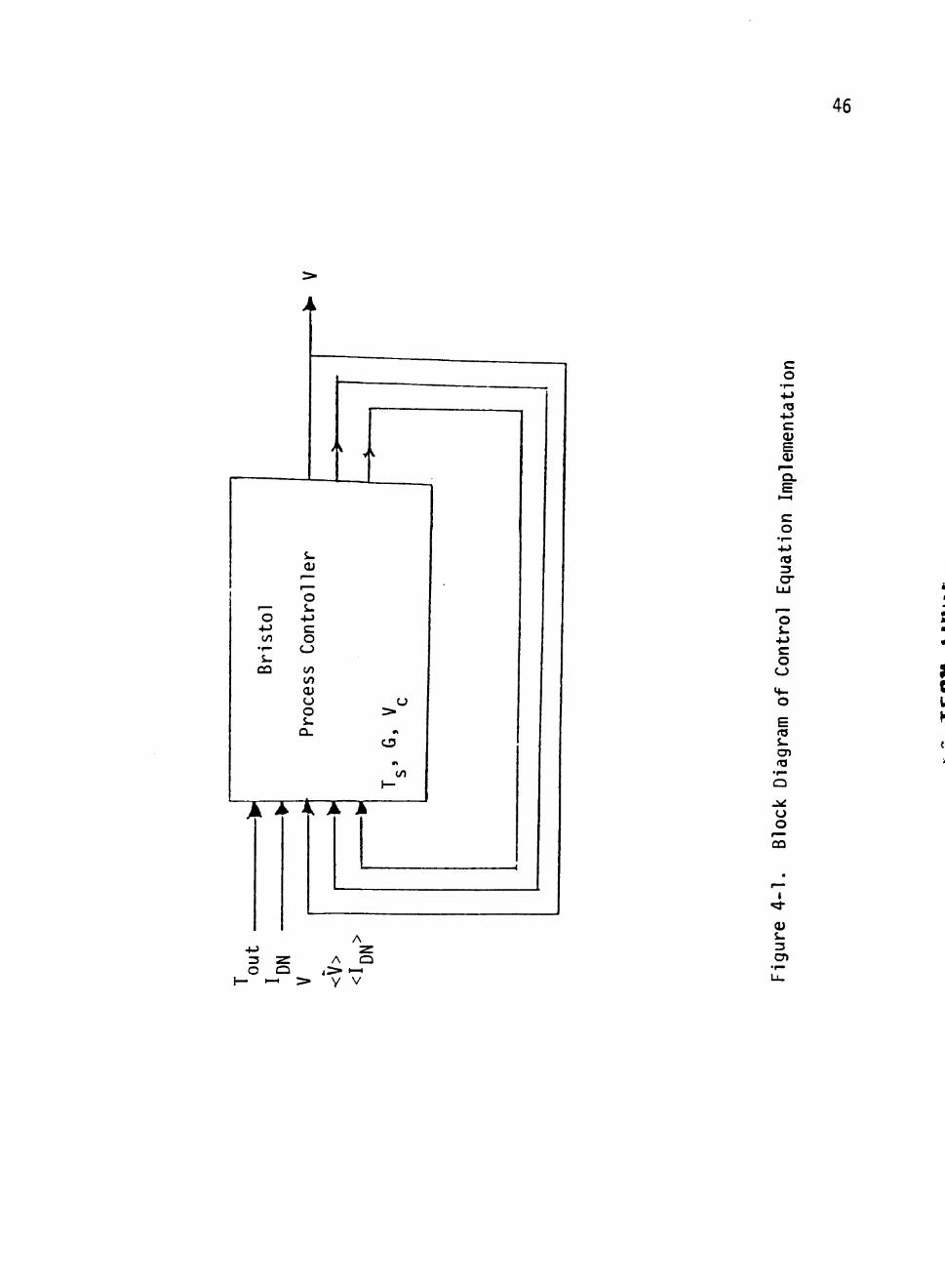
4.1 The Control Algorithm 45
4.2 Strategy for Simulator Development 47
4.3 Computer Simulation Model I 48
4.4 Computer Simulation Model II 52
4.4.1 Mass Flow Rate (M) Curve Fit 61
4.4.2 Calculation of Pp 62
4.4.3 Calculation of Tr 66
4.5 Simulation Model 66
iii
SECTION V TESTING AND EVALUATION OF THE SIMULATION 69
5.1 Simulation Without Using G, 77
5.2 Testing and Evaluation of the Controller. ... 79
5.3 Future Use of the Simulation 84
REFERENCES 86
APPENDIX A PROGRAM AND OUTPUT OF THE M CURVE FIT 87
APPENDIX B TMR CURVE FIT 97
APPENDIX C RESULTS OF STEAM TABLE CURVE FIT 99
APPENDIX D COMPUTER CODE FOR SIMULATION 104
IV
*
LIST OF TABLES
2-1 ALARM AND SHUTDOWN SETPOINTS 25
4-1 M CURVE FIT FOR JULY 5, 1980 63
4-2 M CURVE FIT FOR JULY 30, 1980 64
4-3 STEAM TABLE CURVE FIT FOR EXIT TEMP 67
5-1 COMPARISON OF ^^^^^ vs i|; , 85 ^meas ^calc
LIST OF FIGURES
1-1 System Block Diagram 2
1-2 Fluid Path for the ADVS 4
2-1 Spherical Reflector Ray Tracing 9
2-2 Tilt Angle vs Normalized Annual Energy Capture 11
2-3 Conical Focal Zone with a Cylindrical Receiver 12
2-4 Cantilevered Receiver Structure 14
2-5 System Schematics (Load Skid and the Receiver) for the ADVS 15
2-6 Sample of "Poor Reichert's Almanac" 19
2-7 Scan Table 28
2-8a Scan Figure "P" for July 15, 1980 29
2-8b Scan Figure "I" for July 15, 1980 30
2-8c Scan Figure "T" for July 15, 1980 31
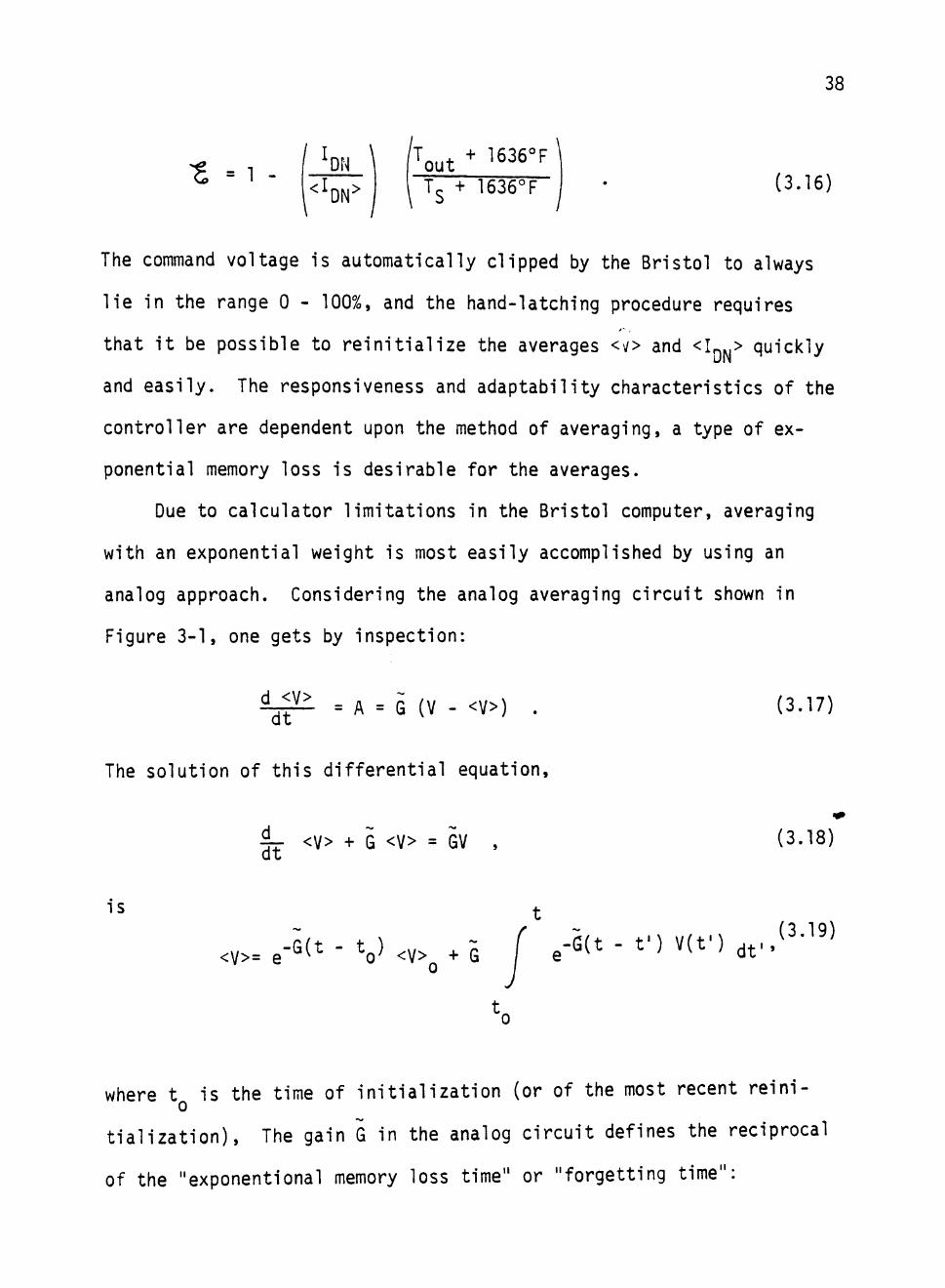
3-1 Analog Averager Circuit 39
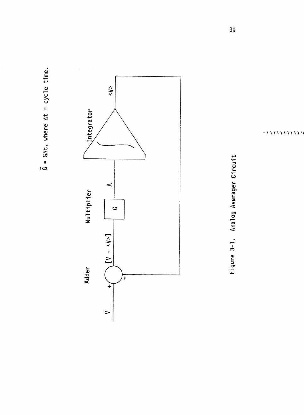
3-2 Implementation of Digital Averager in Bristol 41
3-3 Plots of <V> for Various G 44
4-1 Block Diagram of Control Equation Implementation 46
4-2 Plots of G vs Gj 51
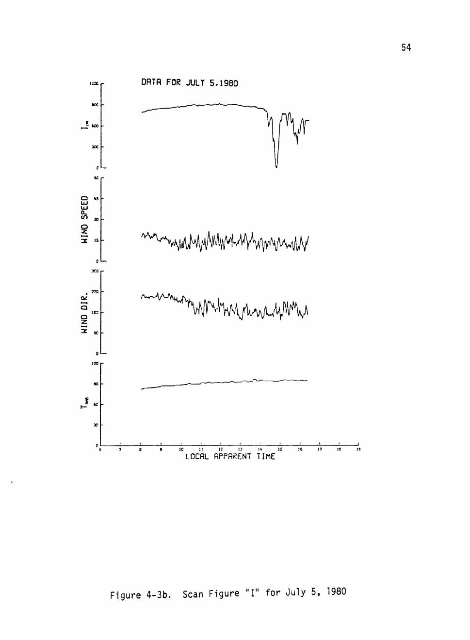
4-3a Scan Figure "P" for July 5, 1980 53
4-3b Scan Figure "I" for July 5, 1980 54
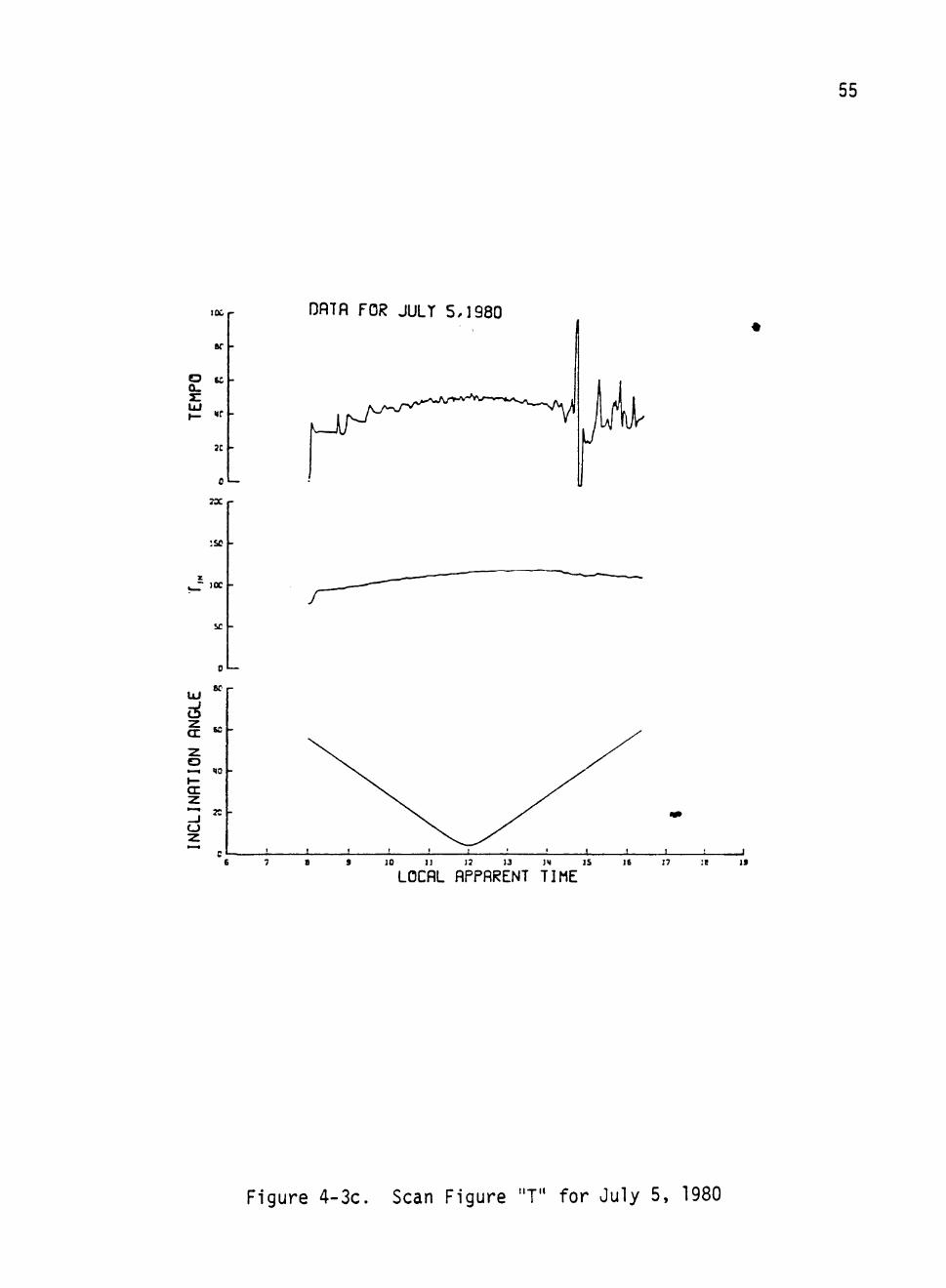
4-3c Scan Figure "T" for July 5, 1980 55
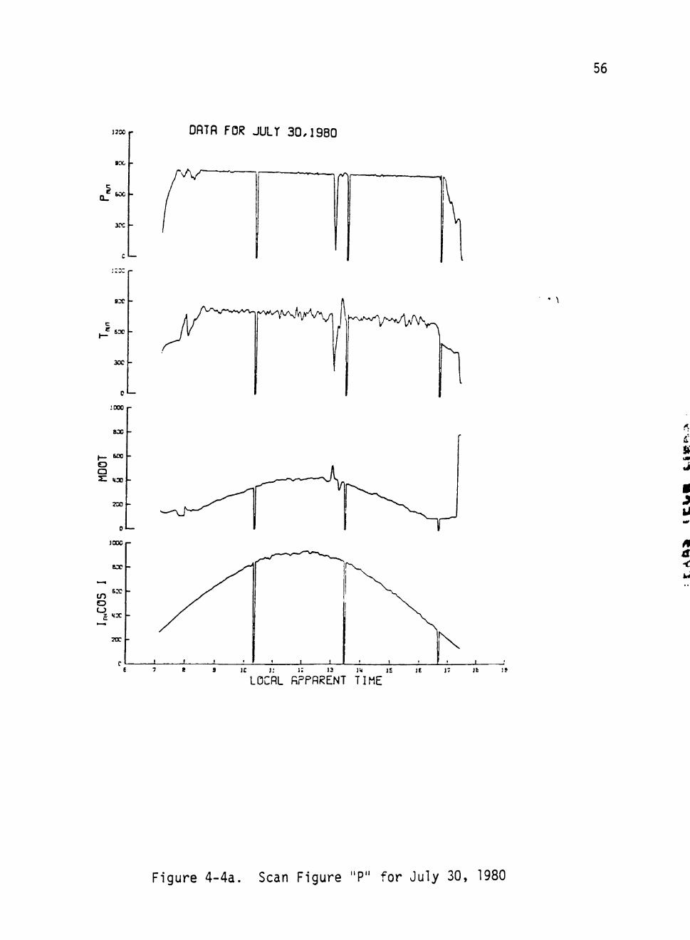
4-4a Scan Figure "P" for July 30, 1980 56
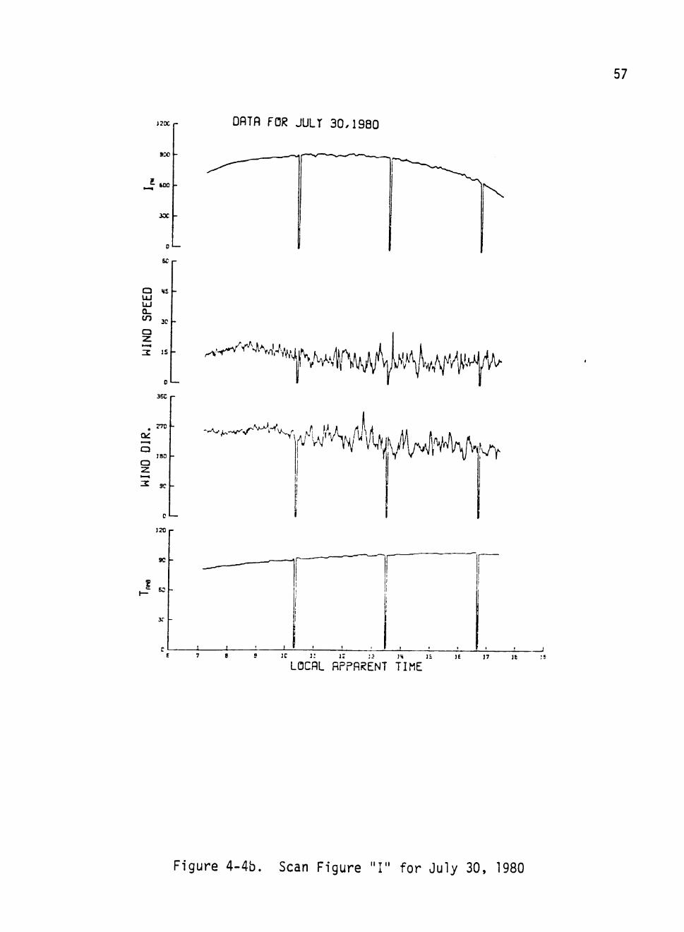
4-4b Scan Figure "I" for July 30, 1980 57
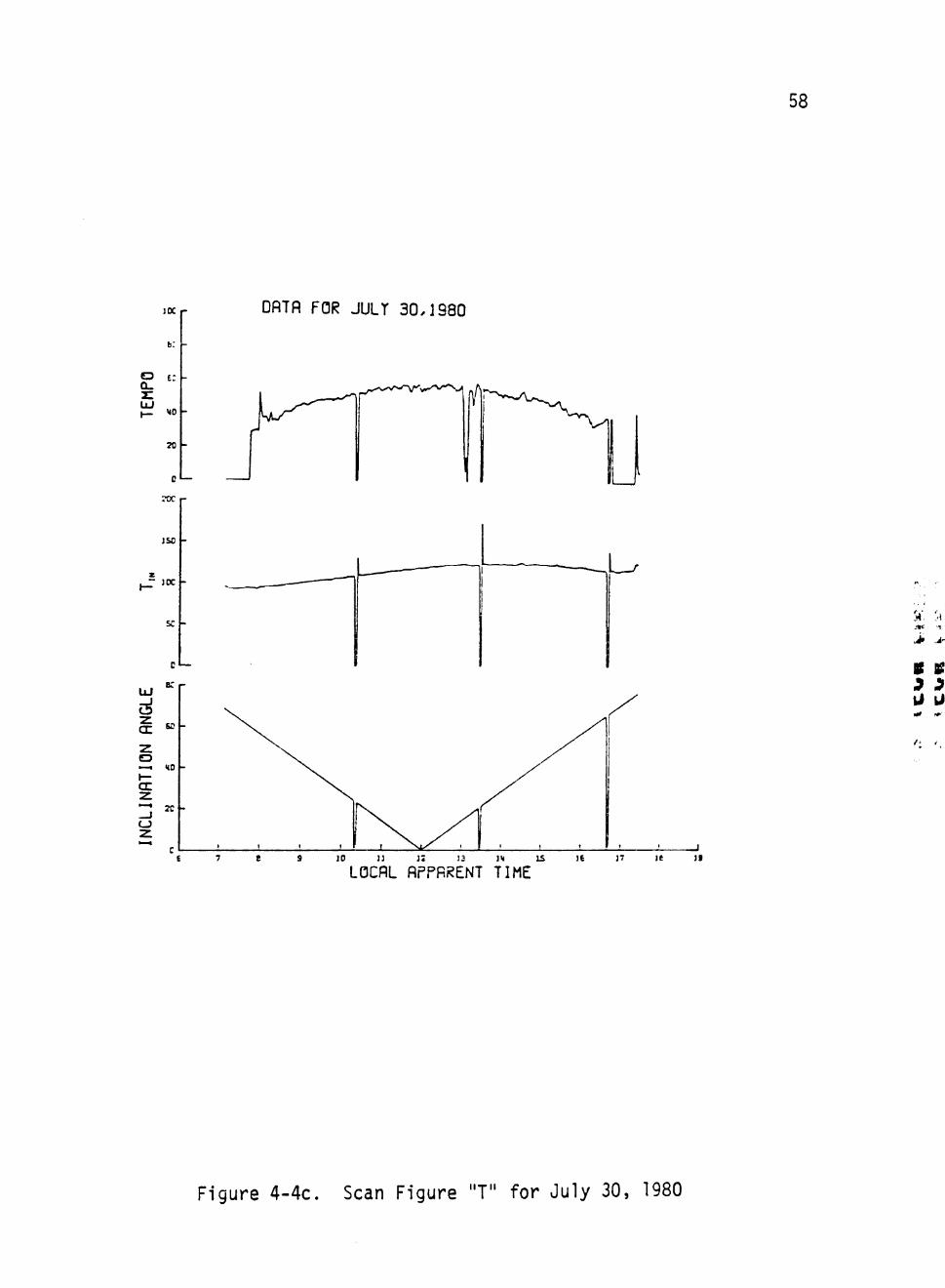
4-4c Scan Figure "T" for July 30, 1980 58
VI
4-5 Results of "Test Simulation Model I" for July 5, 1980 . . . 59
4-6 Results of "Test Simulation Model I" for July 30, 1980. . . 60
4-7 Graphs of M vs V with the Corresponding o Band 65
4-8 Flow Diagram for the Simulation Model 68
5-1 Actual Controller vs Simulated Controller for July 5, 1980 71
5-2 Actual Controller vs Simulated Controller for July 30, 1980 72
5-3 Actual Controller vs Simulated Controller for
August 1, 1980 73
5-4a Scan Figure "P" for August 1, 1980 74
5-4b Scan Figure "I" for August 1, 1980 75
5-4c Scan Figure "T" for August 1, 1980 76
5-5 Actual Controller vs Simulated Controller (Interpolated
Data, Gj not used) 78
5-6 Test Simulation with Various K, Variable Gain 81
5-7 Test Simulation with Various K, Constant Gain 82
v n
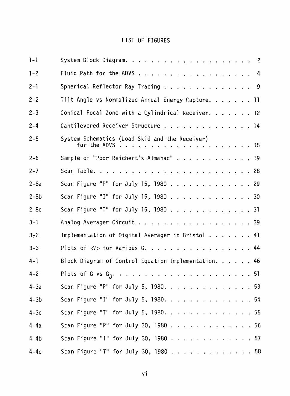
SECTION I
CONTROL OF A SOLAR BOILER
One of the foremost concepts for generation of solar thermal
electric power is the "solar gridiron concept." The concept, also
known as the hemispherical bowl, the solar bowl, and the fixed mirror
distributed focus concept, has been utilized by Texas Tech University
for the construction of the Analog Design Verification System (ADVS).
The ADVS contains the largest single solar collector ever built. The
collector is in the shape of a spherical segment bowl that concentrates
sunlight along a line joining its center of curvature to the sun (the
"solar axis"). The receiver (solar boiler) is located along this axis
and tracks the sun diurnally and seasonally. The focus is "distribu
ted" in the sense that the concentrated sunlight is distributed along
a line interval lying on the solar axis and of length one-half the
spherical radius. Figure 1-1 shows schematically the general arrange
ment of the bowl, the receiver, and the character of the reflected
rays that enter the bowl.
The operation and evaluation of the ADVS by Texas Tech University
began in January, 1980. The ADVS constructed at the test site in
Crosbyton, Texas not only has provided quality steam for generation
of electric power, but also has generated the first commerical elec
tricity from solar steam in the history of the nation.
When in operation, water at approximately 100°F is pumped into
the receiver at the end nearest to the bowl surface. This working
fluid moves through the focal zone in spiral wound tubing and exits
1
ui
- 2 _ u. U X
n y = ^
"
«/i
oe o >-< ee lU Z UJ o
\ *" \ ^ \ -\ SI 1 \ <r / \ 3 / \ •- /
^ UJ
5s « ^
EN
E
ST
OI
/ / »
u. O Q
/ UJ
/ s ' a. 2
O u
TR
AT
OR
^^ UJ _J
U ui 2 Z
AL
CO
V
E
PA
u — — h-* U Ui lu
-- .J iu-£ Hi 2 a: UI
E
O
o CQ
E (U
to >>
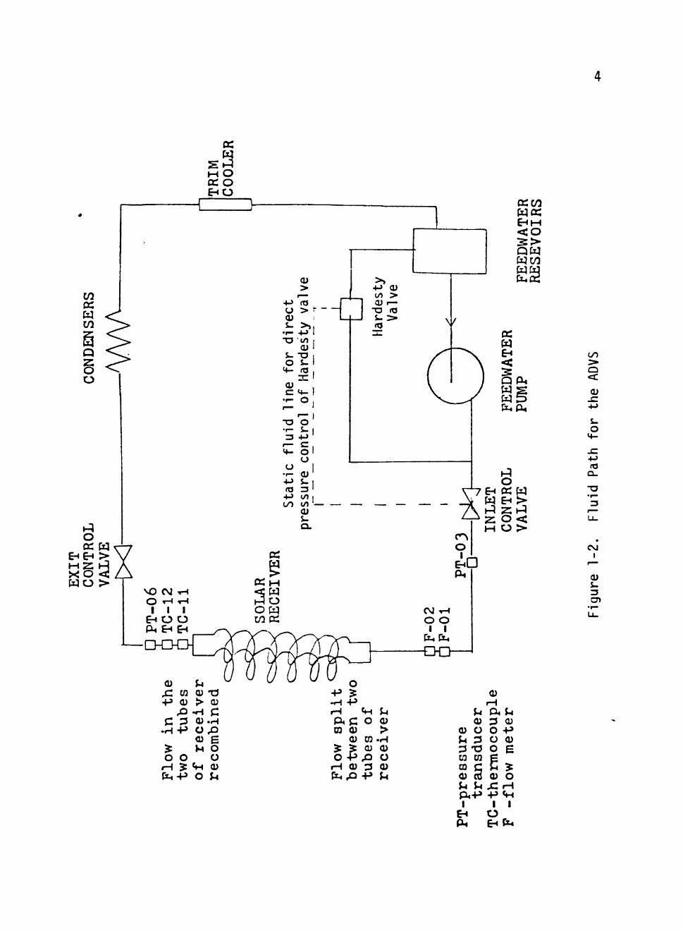
as superheated steam at the top of the receiver. Flexible couplings
and high pressure flexible hoses, located in the vicinity of the pivot
point, are used to bring the water to and remove the steam from the
receiver.
In order to achieve turbine quality steam, it is essential to
maintain relatively constant temperature and pressure. The ADVS pro
cess controller achieves this task by controlling the feedwater and
exit steam valves. It is useful to consider the feedwater (inlet
control) valve as regulating the exit temperature and to think of the
steam exit (exit control) valve as regulating the exit pressure.
Figure 1-2 represents the fluid path for the ADVS.
The ADVS Process Control is accomplished by the Bristol Process
Controller (ref. Bristol Instruments/Systems). Manual, Emergency,
and Active modes are utilized for the Process Control. Manual mode
has the highest priority and can be accomplished either at the Bristol
console by slewing control switches or by manually turning numerous
valves at the load skid (ref. Sec. II). The Emergency control mode
has second priority (overrides anything except the system operator).
If a fault condition is detected by the Bristol in any of the continu
ously monitored sensitive data channels, the Bristol sounds a warning
at the first threshold. If the situation is not corrected and the
condition deteriorates to the second threshold, then the Bristol
automatically takes all steps to safeguard the system. In partic
ular, the emergency control will dictate a "stow"; and move the re
ceiver from the focal region to a safe location. Other actions re
lated to fluid flow control are taken simultaneously if required.
m w
Q
§
o EHEH >
x o <i wo >
CO :> o
o
4->
Q -
-o 13
CO I
Active control is accomplished by the Bristol as it receives sensory
data and uses it to compute suitable command voltages for the feed-
water and steam exit valves (Montec actuator valves). When in the
active mode, the command voltage is generated by the Bristol by
utilizing the sensory data and the algorithms selected for the inlet
and exit valves.
A completely active, memoryless control algorithm was designed
initially for the inlet and exit valve controllers. The algorithm
for the exit valve controller turned out to be quite simple when it
was considered and obligated to control only the exit pressure. The
command voltage responds only to a term like K(P - P^) where P^ is the
desired or set-point pressure, P is the measured pressure and K is a
gain factor. The inlet valve controller is considered to control only
the exit temperature. Algorithms for the inlet valve, using various
pressure (P), temperature (T), and insolation {l^^) terms of the type:
K(P - Pj). K(T - T j ) . Kdp^ - IQ^Q)
were implemented. All such controllers were subject to the following
difficulties.
1. Such controllers are biased (no correct open loop terms).
2. They tend to react too strongly to large transients.
3. They are not stable over the full range of conditions
and phenomena.
4. Nonlinearities in the system can occasionally cause such
terms to turn the valve the wrong way.

5. The hand-operated valves at the load skid are occasionally
reset (and are difficult to return to exactly the previous
position).
6. The Hardesty valve (ref. Sec. II) has idiosyncrasies in its
behavior.
In order to resolve all these problems, a controller was designed
using the concept of conservation of energy (ref. Sec. III). This
study focuses its attention on the algorithm thus developed. Analysis
and simulation of the controller algorithm is accomplished in Section
III and Section IV, while Section II discusses the ADVS in general.
Conclusions derived from the simulation of the inlet controller and
recommendations for future controller development are presented in
Section V.
SECTION II
THE SOLAR GRIDIRON CONCEPT
The Crosbyton Solar Power Project (CSPP) of Texas Tech Univer
sity, funded by the U. S. Department of Energy, utilizes the Solar
Gridiron Concept for planned application of a 5 MW solar-fossil
fuel hybrid electric power plant for Crosbyton, Texas. The Solar
Gridiron Concept is new only in its name. Its history, under various
names, goes back at least a century. The concept in its purest form
has a collector, or mirrored bowl, with no moving mirrors, and a re
ceiver or boiler which moves within the collector to track the sun.
The Gridiron Concept is not simply that the collector is fixed
but includes the use of a spherical segment mirror. There are two
major advantages of the spherical bowl shape:
1. the power on the receiver remains congruent throught the
day; and
2. the focal zone is well shaped for high concentration and
good heat transfer.
The basic function of the collector is to gather the incident
solar energy and concentrate it onto the receiver. The basic pattern
of the light directed into the focal region of the spherical collector
is the same throughout the day and year due to the symmetry of the
collector. This congruence of the pattern of light in the focal region
is useful, and advantage is taken when considering heat transfer and
the materials employed to build the receiver, the tracking of the
7
8
receiver, and the controllability of the fluid in the receiver.
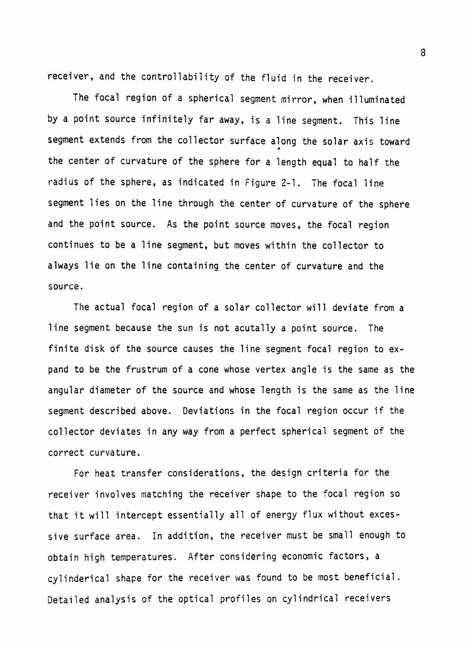
The focal region of a spherical segment mirror, when illuminated
by a point source infinitely far away, is a line segment. This line
segment extends from the collector surface along the solar axis toward
the center of curvature of the sphere for a length equal to half the
radius of the sphere, as indicated in Figure 2-1. The focal line
segment lies on the line through the center of curvature of the sphere
and the point source. As the point source moves, the focal region
continues to be a line segment, but moves within the collector to
always lie on the line containing the center of curvature and the
source.
The actual focal region of a solar collector will deviate from a
line segment because the sun is not acutally a point source. The
finite disk of the source causes the line segment focal region to ex
pand to be the frustrum of a cone whose vertex angle is the same as the
angular diameter of the source and whose length is the same as the line
segment described above. Deviations in the focal region occur if the
collector deviates in any way from a perfect spherical segment of the
correct curvature.
For heat transfer considerations, the design criteria for the
receiver involves matching the receiver shape to the focal region so
that it will intercept essentially all of energy flux without exces
sive surface area. In addition, the receiver must be small enough to
obtain high temperatures. After considering economic factors, a
cylinderical shape for the receiver was found to be most beneficial.
Detailed analysis of the optical profiles on cylindrical receivers
> X I A L MAY
center of cur_y£ture
"Ik
] nerucTiNO
Figure 2 -1 . Spherical Reflector Ray Tracing
10
this can be found in B. Brock and H. S. Leung work (ref. SB and HL).
2.1 The Analog Design Verification System (ADVS)
The CSPP preliminary design for the 5 MW power plant requires
construction of ten Solar Gridirons each with 200-foot aperture dia
meter (ref. CSPP III). In order to provide a sound basis for assess
ment of the expected performance, cost, and economic value of the
contemplated 5 MW power plant, an Analog Design Verification System
(ADVS) was constructed.
The ADVS is a fully instrumented Solar Gridiron which was
brought to operational status on January 22, 1980, in Crosbyton, Texas.
The ADVS contains the largest primary solar collector ever built. This
collector is a quarter-sphere composed of 430 mirror panels of 12
different shapes laid out on the surface of a 75-foot diameter sphere.
The rim angle of the collector is 60°, so that the aperture diameter
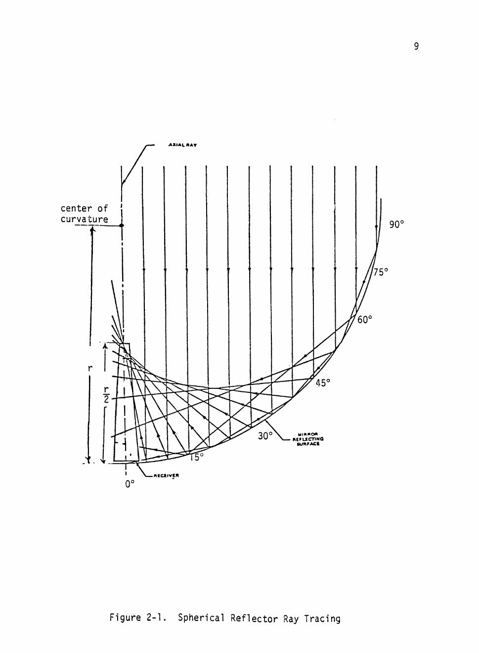
is 65 feet. The collector is tilted 15° to the south. The annual
energy capture could be maximized by tilting the bowl to an angle
equal to the latitude of the collector, which is 33-5/8° for Crosbyton,
Texas. However, as shown in Figure 2-2, 85% of the maximum benefit
available from tilting the bowl is obtained with 15° tilt (ref. KW).
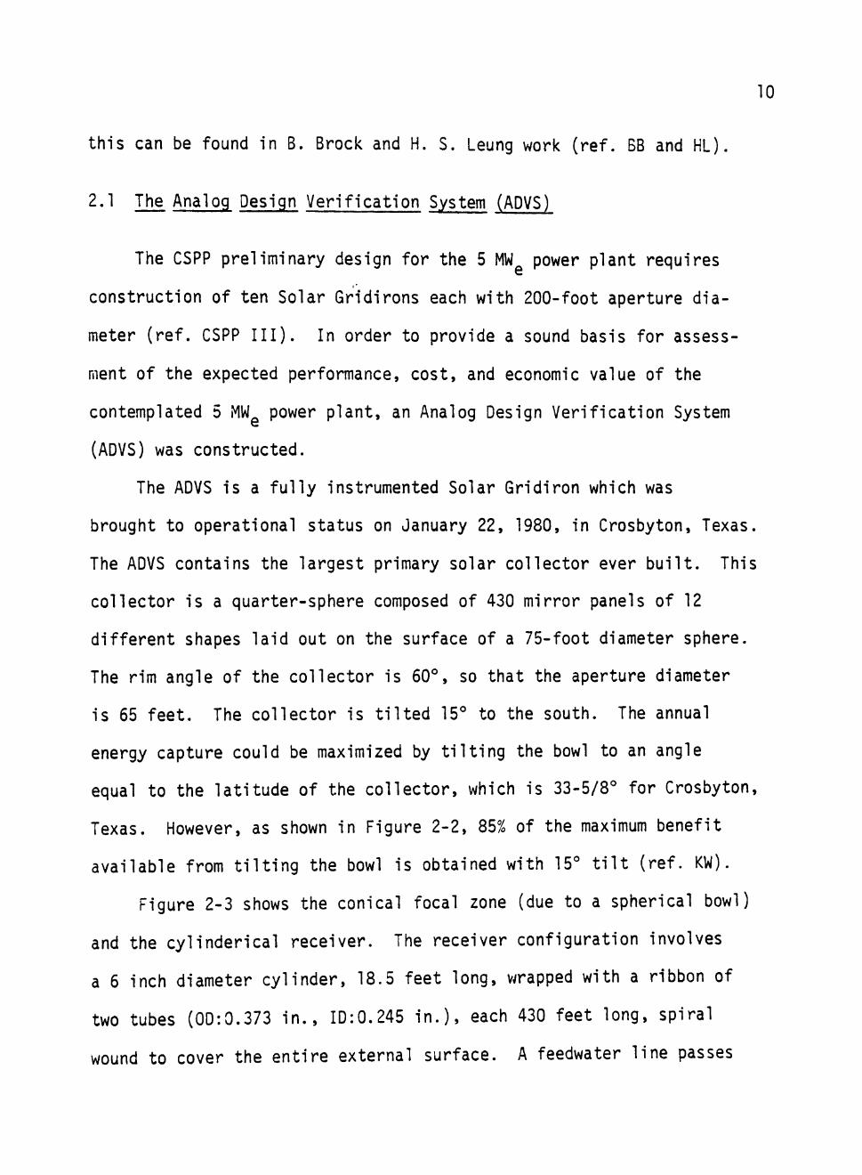
Figure 2-3 shows the conical focal zone (due to a spherical bowl)
and the cylinderical receiver. The receiver configuration involves
a 6 inch diameter cylinder, 18.5 feet long, wrapped with a ribbon of
two tubes (00:0.373 in., ID:0.245 in.), each 430 feet long, spiral
wound to cover the entire external surface. A feedwater line passes

11
O
CO
o"
o" >-CD LU •! •z. o
<: I— LD O •-h- O Q UJ
a: o
o—
o
Latitude = 30°
'T
IS 60 ~\—
75 0.00 30 r
45
"T-90
TILT ANGLE
Figure 2-2. Tilt Angle vs. Normalized Annual Energy Capture
12
a is the angular radius of the solar disc.
Figjre 2-3. Conical Focal Zone with a Cylindrical Receiver
13
down the interior of the support cylinder to feed the two tubes at the
bottom of the receiver. A mid-span plenum manifolds the flow about
half-way up the receiver, and then the tube continues on up to a re
ceiver exit manifold at the top of the receiver.
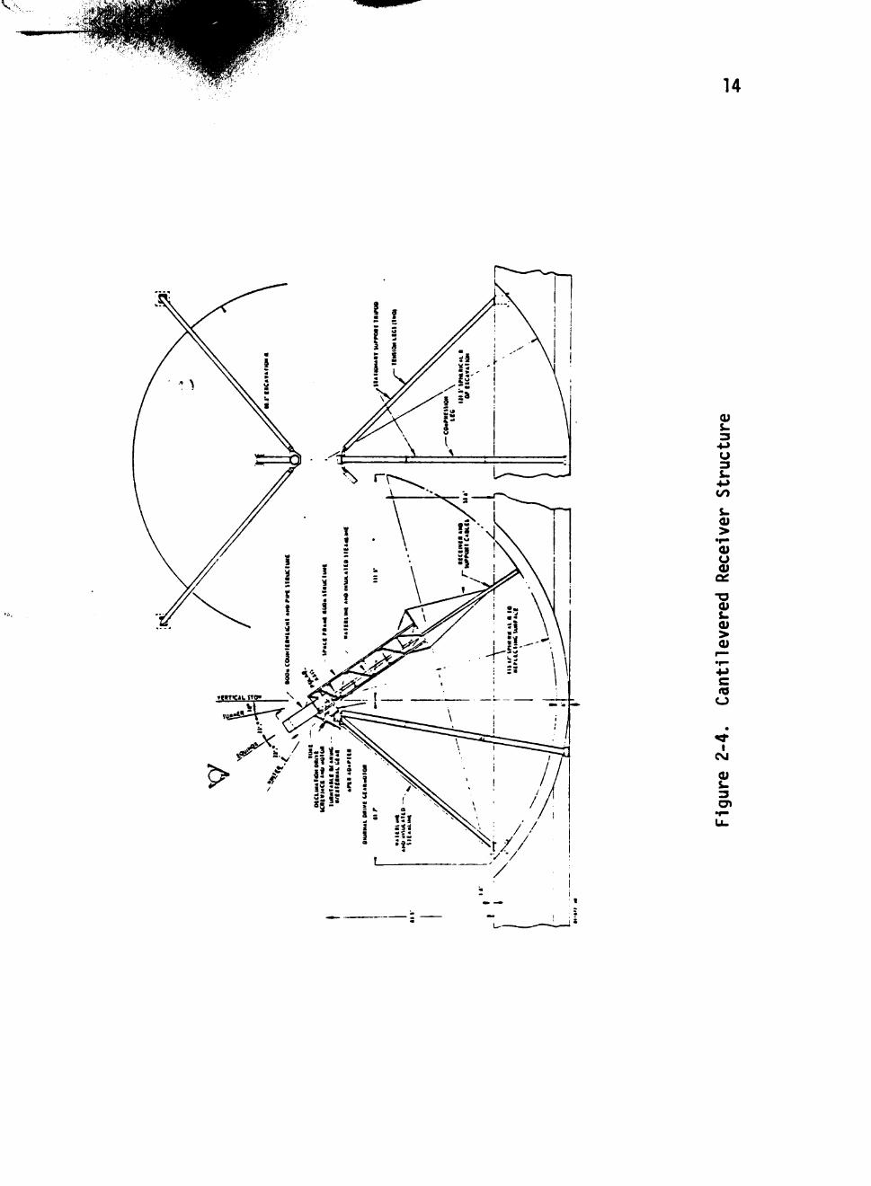
The structural support of the ADVS bowl consists of four north-
south concrete backbones supported by concrete pillars in a partial
excavation. Twenty-five east-west ribs of four inch pipe cross the
backbones to support the 430 mirror panels. The cantilever support
beam for the receiver is mounted on a pivot point supported by a
north-leaning tripod with two legs in tension and one in compression.
Footings for the tension legs are outside the aperture structure, so
that only the compression leg penetrates the bowl. These features are
illustrated in Figure 2-4, a preliminary design for a 20G-ft. bowl.
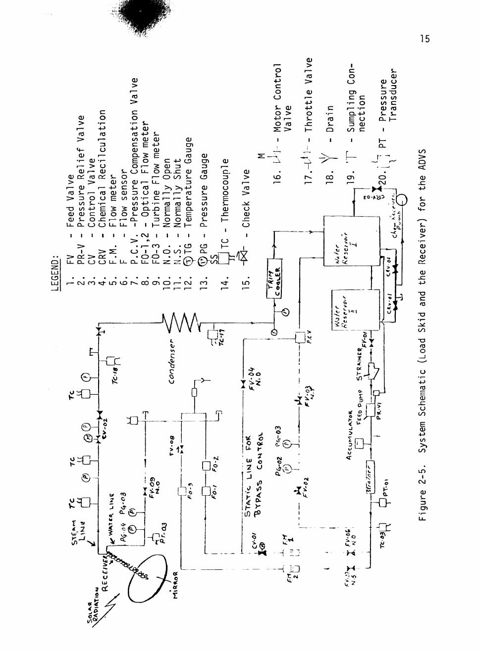
Articulation of the fluid lines at the pivot point is accomplished
by two flex-hoses: one for feedwater and one for the exit steam. A
system schematic is given in Figure 2-5. The ADVS is a closed-loop
systSfli. The water is pumped to the solar boiler by a feed pump. Steam
from the solar boiler is condensed, cooled, and returned to the system
reserviors for recirculation. Flow of feedwater to the receiver is
controlled, not by a shunt wound DC pump motor, but by a by-pass valve.
Originally, feedwater flow was regulated by a Montec actuator operating
a valve in the by-pass line. A second Montec actuator controls the
pressure in the steam exit line. Gil Hardesty, a consultant to E-Sys-
tems, suggested the new location for the feedwater actuator control
valve (CV-01) shown in Figure 2-5 with insertion of a pressure-com-
pensating-valve (also referred to as "the l-laraesty valve") 'n the
wm'
. ^ ^
14
0) s-3
4>> U 3 i .
4-> CO
&.
>
(J 01
-o i.
> 0)
I
s . 3
15
>
T—
o s-+-> d o o $- <u o >
+-> r— o m
2 : >
(U >
r ^
rO >• (U
r ^
4-> 4-> 0 S-
JC 1—
E • r— fO s-
Q
1 c 0
C_)
0 ^ c
• r -r ^
c 0
• r— CL+J E =3
CO
0 O) c
s-OJ
<u 0 $- 3 3 - 0 to to to C OJ ro S- S-
Q . 1 —
1
LU
CO :> Q
<: <u
4->
S-
o
>
o <u
(U
J 4-> -o c OS
CO
as o
u ' I —
4-)
o CO
O) +J to >»
CO
I
CM
(U
s _ 3
16
by-pass line. A static line downstream of the control valve reads the
exit pressure and communicates with the pressure-compensating-valve
(p.c.v.) to adjust flow in the by-pass line. The intent of this ar
rangement was to try to maintain a constant pressure drop across the
control valve. Such a situation would act to reduce the tendency of
pressure surges from the receiver to shunt feedwater into the by-pass
line. The Hardesty valve in use does not maintain a constant pressure
across the control valve, but does make the system much easier for the
Bristol to control.
2.2 Bristol Process Controller
The Bristol process controller (UCS 3000) is a system that per
forms a multitude of process operations through the use of digital
programming techniques. The device is essentially a microprocessor
computer with programming and storage facilities. Bristol process
controller is programmed with a series of software modules that ef
fectively perform hardware functions. Bristol also has a process
operator panel (POP) which interfaces the process operation with the
Bristol process controller. The POP enables the operator to monitor
signal level, alter set-points and output levels, and change servicing
rates and priorities of the program as required. The Bristol Process
Controller serves three basic functions in the ADVS.
1. Tracking of the ADVS Receiver,
2. ADVS Process Control, and
3. Emergency Alarm and Shutdown.
17
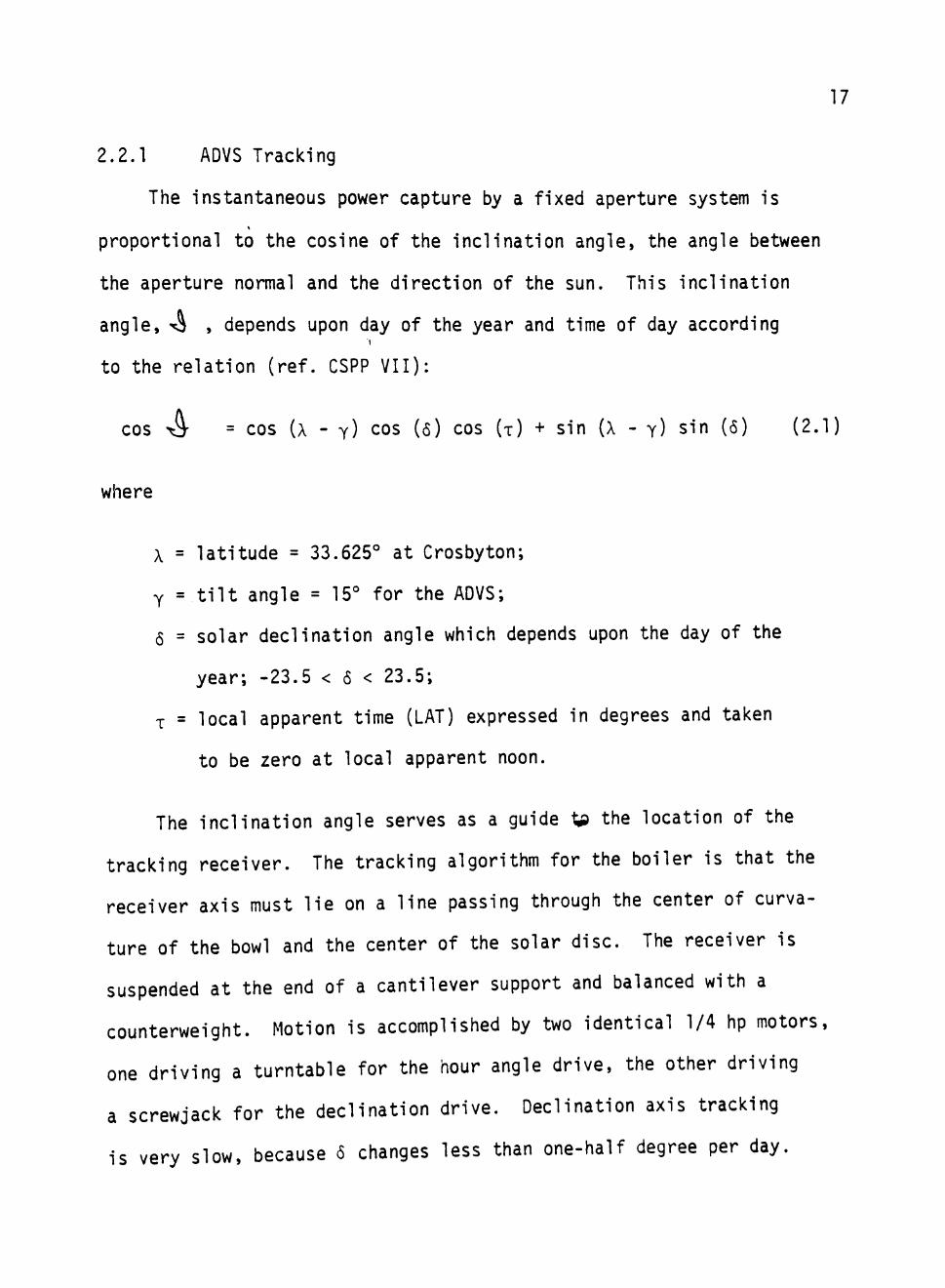
2.2.1 ADVS Tracking
The instantaneous power capture by a fixed aperture system is
proportional to the cosine of the inclination angle, the angle between
the aperture normal and the direction of the sun. This inclination
angle, S , depends upon day of the year and time of day according
to the relation (ref. CSPP VII):
cos
where
^ = cos (A - y) cos (6) cos (x) + sin (X - y) sin (5) (2.1)
X = latitude = 33.625° at Crosbyton;
y = tilt angle = 15° for the ADVS;
6 = solar declination angle which depends upon the day of the
year; -23.5 < 5 < 23.5;
T = local apparent time (LAT) expressed in degrees and taken
to be zero at local apparent noon.
The inclination angle serves as a guide ^ the location of the
tracking receiver. The tracking algorithm for the boiler is that the
receiver axis must lie on a line passing through the center of curva
ture of the bowl and the center of the solar disc. The receiver is
suspended at the end of a cantilever support and balanced with a
counterweight. Motion is accomplished by two identical 1/4 hp motors
one driving a turntable for the hour angle drive, the other driving
a screwjack for the declination drive. Declination axis tracking
is very slow, because 5 changes less than one-half degree per day.

18
Hour angle tracking involves a "fast axis" because x proceeds at 15°
per hour.
Tracking control is accomplished by the Bristol process controller
and various modes are used: Clock Drive, Active Drive, Automatic Drive,
and Manual control. Though seldom used for actual tracking, the Manual
Control Mode has the highest priority. Manual is simply control ac
complished by the system operator. He may move the recei^ver at his
discreation in either hour angle x (east-west), or declination 5 (north-
south), or both simultaneously. This is accomplished at the controller
console (POP) by slewing a potentiometer.
Clock Drive is automatically accomplished by the Bristol using
X (obtained from its real-time clock) and 6 (obtained from a memory
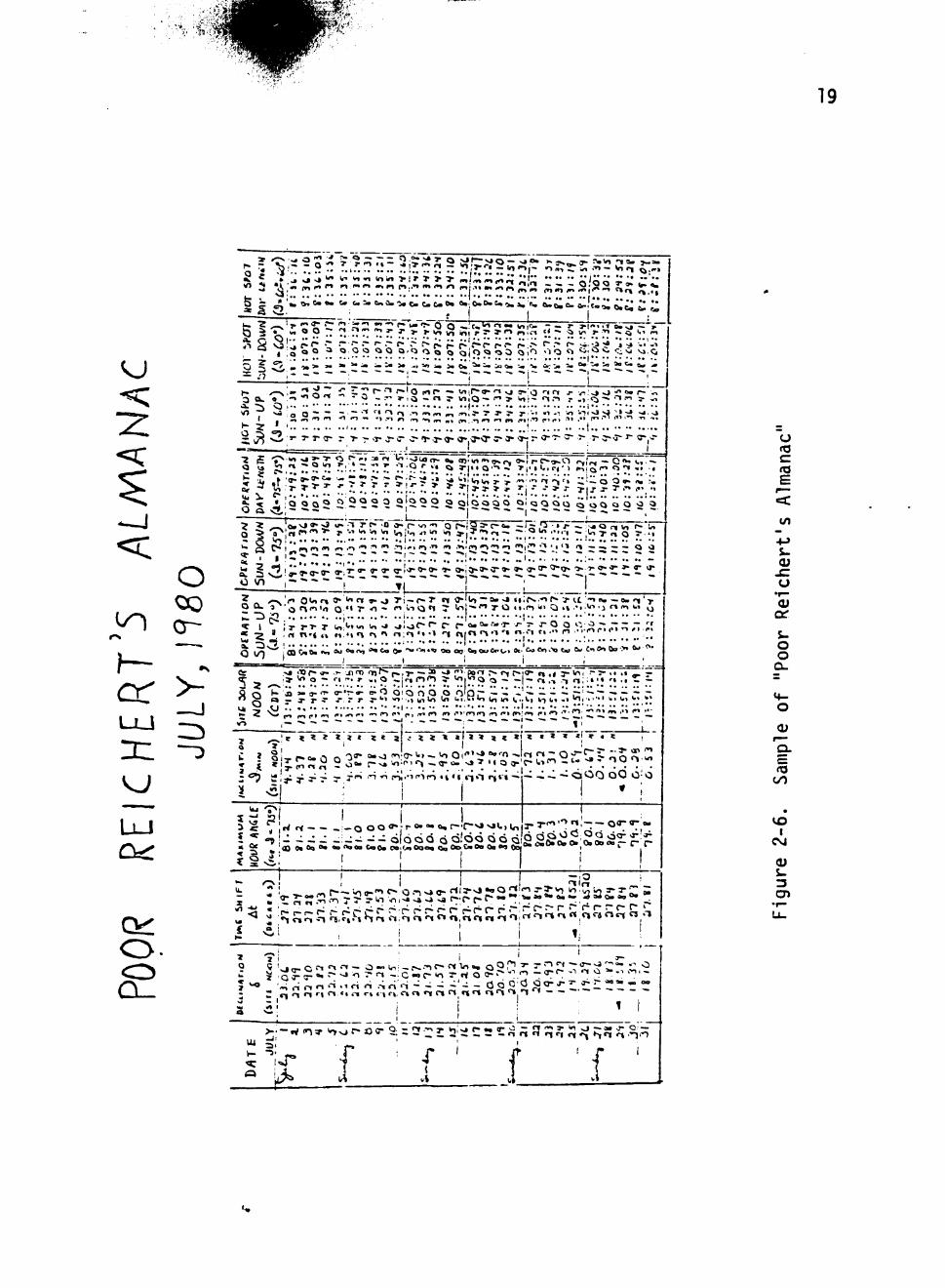
updated each day). An almanac is available at the site in two formats:
"Bristol operators: Each Day" and "Poor Reichert's Alamanac" (ref.
Figure 2-6). These resources are used each day to set 6 and to reset
the LAT (local apparent time) with respect to the real time civil
clock. Throughout the day the Bristol determines x and 6 and substi
tutes these two parameters in the tracking command voltage curve fits
to determine and send out open loop command voltages to the two inland
motors. A feedback loop assures that the command is properly imple
mented. The curve fits mentioned above are updated about once a
month, as they begin to lose accuracy. The purpose of these fitting
functions is to account for any and all nonlinearities in the elec
tronics, offsets and biases, mechanical deflections and imperfec
tions, gravitational effects, as well as any structural misalignments.
19
o
or > - J ID
a^
O Q_
I
— .'7
%x " ' ? ~ ?.. r? — T.r. r '^ .»• i- S « ; r I- * •-> n IM tj - fs ^ I- 7 - . 5 1.1 m
, ;2 o o ^ « <? w f i ? ° ' ^ o o <s o l o p o o o in o o < ^'^?^T r^i^ " ^ ^
5 / J T « » > » " i " - ^ — i " 5 » - . = " : - J . 6 i ^ ^ i c . i i . - - l . i r - j . = . 0 " ' ^ > i ^ a » ' «
I
' ^ ; ^ - i Q t ^ - 0 - r ' j - , o ~ r t r w i l o - - . - i 3 . w , i ~ < n . ~ i r o « 5 ' > ' ' ^ " s - - '
^ o O ~ •"• "^ '^ < •> <.» m ,., 1.1, J- ?• •>• 3- J- '•' " -•; '•« o i -J vj ;^ •-» >j. , j
• t , . , , , „ , , , , t , , . , i . , . . , . . , , Q -e O , '" ' • *• •• •" ' ' • ' • '
I
•2
^ V, : J- T 5 ' ^ ' ; ; • . . f i r . '^ *l3-3- > 1- 7- •.-,-» r firs-T'^c •>
5
^ J L ; Q O Q 2 2 - , 2 2 2 ' 2 r 2 2 2 ' 5 2 9 ^ Q ' O O Q O Q O Q O Q 5 2
^ -~.lo.•^ »• s? «^ 1 r c» .0 0^ (~ wi -.1 Q f ^ i g a - r - a . — I ^ ,Tf •» P ~ •.• o ri vi r-'CT"
r r.. I T| "I r ! >-s'<^ 0 ' o r » » ' ' " < T I » ' O T i ~ p » T PI o l i o — 0 . v» « i ;p^ . -oS . 3- n -n « , ~.o» 1 '-J-
" - 3 ' o f ^ ^ ' i 0 ' « T " 0 - r i i . i ( 3 t | 5" t n - " " T 0 4 i , n i . i O « v ' > ' " ' J ' ^ ' ^ " u "HiS . . ; •- ••1.
^ » : » n T i l n : . | i ^ i ^ • ^ n ; ^ . . . 1 T i ; , n r , o ' . o..-, r . . . . n . . ; ^ r . . . . ^ „ , .
5 °5 • I •• '
»o ;>j ••Of- v.,»-'j iro iTj>- f-.,7- —2? ^ ."^ fts*^ > «~i r-i"'" n .1 7- "^i •"=" " •• <p. r ' , * V> o - n " . r . , a V l j r , f - ) ( ^ 3- V n . R o o -• - | - r« !•. ^ a : » ; • ' • • • ^ -
^.^a ' -a- ' ' " o-••:-»- o-o Q i Q o o o O'Q r " ^ - - ' - ^ — - ~ , - - ' ^ — ~ ca -• 3- r ~ -r. T r j - >•» " i ' . , m to In u i . n i r i i „ i,, (..,(,, i-, ( , , . , i n , . . . . i wi U) w ,w. <j r, •• ••! •• •• •• •• •• I •• •• •• •• i i ' 'j.~\ " ;; lA ..'• V.» ^ „ n 1.^ !•• , n » • ..^ 1.1 < • » ( . , , » • 1.1 !.> i-">'(T>,r| ^ »> (».;•<.» ^ , r^ . . . i - l . _^ m , ^ r " __
I - • * . ; , , ;
^^r t « « Z Z ( < « J . . - % « « * 1 4 « < < < < * " i~«- i | -
Is Pi rl Ti - I — O O O " ^ j T o. •» o , r - ' r ~ v » ^ t ) l o
^ 0« OQ 0« ^ <^09 — d l o o d o d!o<S Q 6 <i C«0« &»iOi9 0QO« Qq Oo< CM ft» Oa on Oo
Q d p O < i ; O Q o<r r r
0 2 I
_ '-.> i-i n " •"* "^ <"« "^ ~ r% >^ rt r\ n 't .-t r
Ol > ; -w n:>- 'o^'p-oo- 2:: '? ' : :3: !2:: iC2?:n a fJ n - ' " ^ ^ " • ^ ' n n ft 1 Nn r\ o —
} {
vi f 1
(J
c E
t o
o o Q-
<U
CO
U3 I
CM
0)
3
20
Data for the curve fits is taken by direct visual observation of re
ceiver alignment throughout the day as a function of the command volt
ages.
The Bristol operator customarily updates the curve fit (by
trivially resetting a bias) throughout the day, if and as required.
When such actions become too frequent or too necessary, a new curve
fit is made. As will be explained below, the clock drive is always
used for the declination drive, but is only a default option for the
hour angle drive.
Active Tracking Drive is available for both axes, but is only
used in practice for the hour angle drive (the fast axis). Declina
tion changes so slowly that the active tracker for this drive is just
not necessary. Each axis is fitted with a bifurcate solar detector
which generates a difference signal if the two elements of the sensor
do not receive equal illumination. This difference voltage is fed
back to the Bristol which responds to zero the signal and, thereby,
align the receiver.
Automatic Drive is hierarchal controller which automatically
selects Clock Drive or Active Drive mode depending upon solar bright
ness. The system operator can elect Clock Drive or Active Drive or
Automatic Drive. For convenience. Automatic Drive is employed almost
all of the time. In Automatic Drive the Bristol will select Active
Drive if the insolation is above a selected threshold. Otherwise,
Automatic Drive will default to Clock Drive until the insolation
again exceeds the threshold.
21
2.2.2 ADVS Process Control
Process Control is accomplished by the Bristol in much the same
fashion as tracking control. Manual and Active are the two control
modes being utilized for process control. Although the active control
is somewhat primitive, it can definitely hold exit temperature and
pressure much steadier under transient conditions than a system oper
ator can with Manual Control.
Manual Control is accomplished at the Bristol console in the same
fashion that Manual Drive is conducted: by slewing control switches.
There is an alternate version of Manual, however. One can work directly
at the load skid and turn numerous valves in addition to the two oper
ated by the Bristol. These additional valves are used to adjust the
flow regime to the control range of the Montec actuators (CV-Ol and
CV-02).
Active Control is accomplished by the Bristol as it receives
sensory data and uses it to compute suitable command voltages and send
them to the Montec actuators for the feedwater valve (CV-01) and for
the steam exit valve (CV-02). It is useful to consider the feedwater
valve as regulating the exit temperature and to think of the steam
exit valve as regulating the exit pressure. In this picture, control
of the exit valve and, hence, control of the exit pressure is rea
sonably simple. One need only establish a simple feedback control
algorithm in which the command voltage responds to terms like
K(P - P^), where P^ is the desired or set-point pressure, P is the
measured pressure, and K is a gain factor.
22
The control algorithm for the feedwater valve must be consider
ably more sophisticated. At least three difficulties face the de
signer of the control algorithm.
1. The Hardesty valve (ref. Sec. 2.1) has idiosyncrasies in
its behavior.
2. The hand operated valves at the load skid are occasionally
reset (and are difficult to return to exactly the previous
position).
3. Too many sensors are involved: system behavior depends
upon a great many parameters, and very few sensors are truly
reliable enough to trust with survival of the boiler.
A much more direct approach is to build a completely active
memoryless control algorithm in the sense of using various pressure
(P), temperature (T), and insolation (I j ) terms of the type:
K{P - P^). K(T - T 3 ) . Kdo^ - IQ^Q)
as was done for the steam exit valve. Although quite a few control
algorithms of this type were implemented, all were subject to the
same type of difficulties:
i) such controllers are biased (no correct open loop terms);
ii) they tend to react too strongly to large transients;
iii) they are not stable over the full range of conditions and
phenomena;
iv) nonlinearities in the system can occasionally cause such
terms to turn the valve the wrong way; and so forth.
23
Various derivative and integral terms were also investigated with re
sults that were sometimes better and sometimes worse.
It was decided to define a controller algorithm that avoided most
of the difficulties and to try to make it work well enough that its
defects could be understood. The following algorithm was introduced:
V = <V>+ (V(, - <V>)g (2.2)
wnere V is the command voltage which will be clipped to never be sent
out larger than a maximum V which corresponds to a near zero flow
rate, M = 0, or smaller than zero, corresponding to a closed valve.
The parameter V^ is to be chosen "out of range"; i.e., V^ > V so ^ L m
that, always, V^ - <V> > 0. The average, <V> of the command voltage
is defined with a limited memory. Development, analysis, and simu
lation of this algoritm is discussed in Section III and IV.
2.2.3 Emergency Control
The Emergency control mode overrides anything except the system
operator. Sensitive data channels are monitored e^ery 0.4 seconds by
the Bristol process controller. If a fault condition is detected by
the Bristol in any of the continuously monitored sensitive data chan
nels, the Bristol sounds a warning at the first threshold. If the
situation is not corrected and the condition deteriorates to the
second threshold then the Bristol automatically takes all steps to
safeguard the system. In particular, the emergency control will
dictate a "stow"; and move the receiver from the focal region to a
safe location. Other actions related to fluid flow control are taken
24
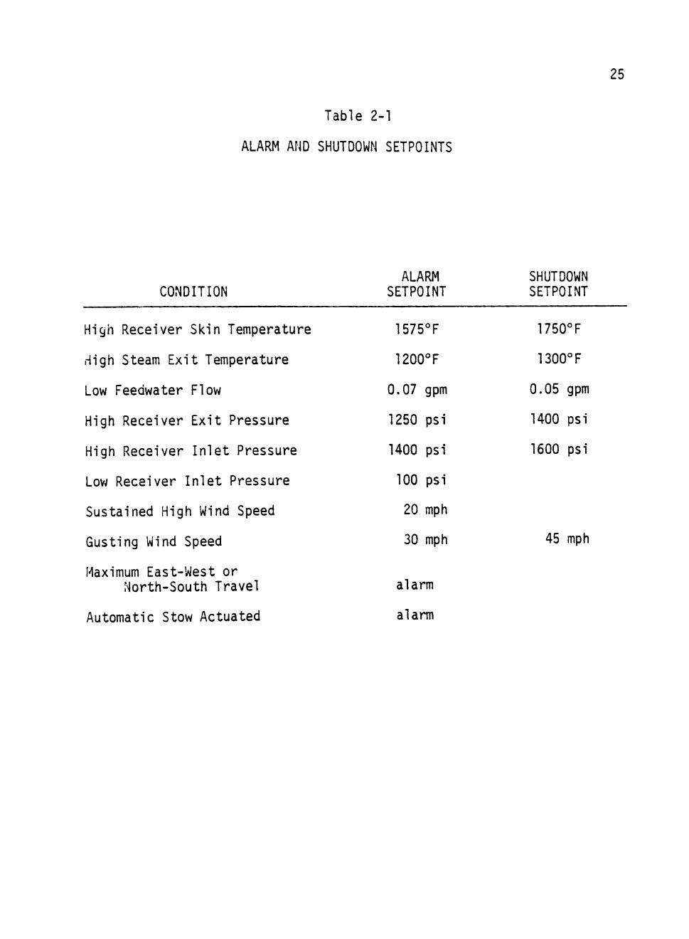
simultaneously if required. Table 2.1, gives a list of data channels
monitored by the Bristol and the two threshold values for each chan
nel .
2.3 Data Acquisition, Storage, and Handling
The ADVS was designed to collect data for test purposes. The
full sensor array of the ADVS includes:
72 thermocouples (12 not yet installed)
5 flow rate detectors (2 not yet installed)
9 pressure transducers
10 command signals for automatic control
10 weather and insolation sensors
which are available to the automatic data acquisition system (DAS). In
addition, there are about 40 gauges, meters, indicators, and displays
available for real time visual inspection plus the CRT display capa
bility of the status and activities of the automatic system controller.
The simulation and analysis of the feedwater valve algorithm,
presented in Sections III, IV, and V, relies upon data from the following
sensors:
1. TC05: a thermocouple monitoring solar boiler (receiver)
feedwater temperature.
2. TCll: a thermocouple monitoring the steam temperature
in the receiver exit manifold.
3. FOl: a mass flowrate detector monitoring the boiler feed.
25
Table 2-1
ALARM AND SHUTDOWN SETPOINTS
ALARM SHUTDOWN CONDITION SETPOINT SETPOINT
High Receiver Skin Temperature 1575°F 1750°F
High Steam Exit Temperature 1200°F 1300°F
Low Feedwater Flow 0.07 gpm 0.05 gpm
High Receiver Exit Pressure 1250 psi 1400 psi
High Receiver Inlet Pressure 1400 psi 1600 psi
Low Receiver Inlet Pressure 100 psi
Sustained High Wind Speed 20 mph
Ousting Wind Speed 30 mph 45 mph
Maximum East-West or North-South Travel alarm
Automatic Stow Actuated alarm
26
4. F02: a second mass flowrate detector monitoring the boiler
feed.
5. PT06: a pressure transducer monitoring the steam in the
receiver exit manifold.
6. R02: a tracking pyrheliometer monitoring the direct
normal insolation.
7. R04: a second tracking pyrheliometer monitoring the direct
normal insolation.
8. WSOl: a horizontal-wind-speed detector.
9. WD: a horizontal-wind-direction detector.
10. AMB: an ambient temperature detector.
11. CVCl: command voltage sent by the Bristol controller to
the feedwater valve.
12. PSDT: presence detector (insolation) voltage from a de
tector mounted on the tracking boom.
The various data channels are brought to the Hewlett-Packard
Model 3052A Automatic Data Acquisition System (DAS), built around the
HP 9845S computer. Acquired data is termporarily stored on diskettes
(floppy disks) and later transferred to nine track tape.
The tapes are transported to TTU for computer processing. The
raw data is transferred to the Raw Data Tape for permanent storage.
All channels in service are called back and the recorded voltages are
converted to physical units, using the calibrations in effect when the
data was taken. This converted data is transferred to the Process Tape
for permanent storage. The data handling system is fully described
in S.Chao' thesis (ref. SC).
27
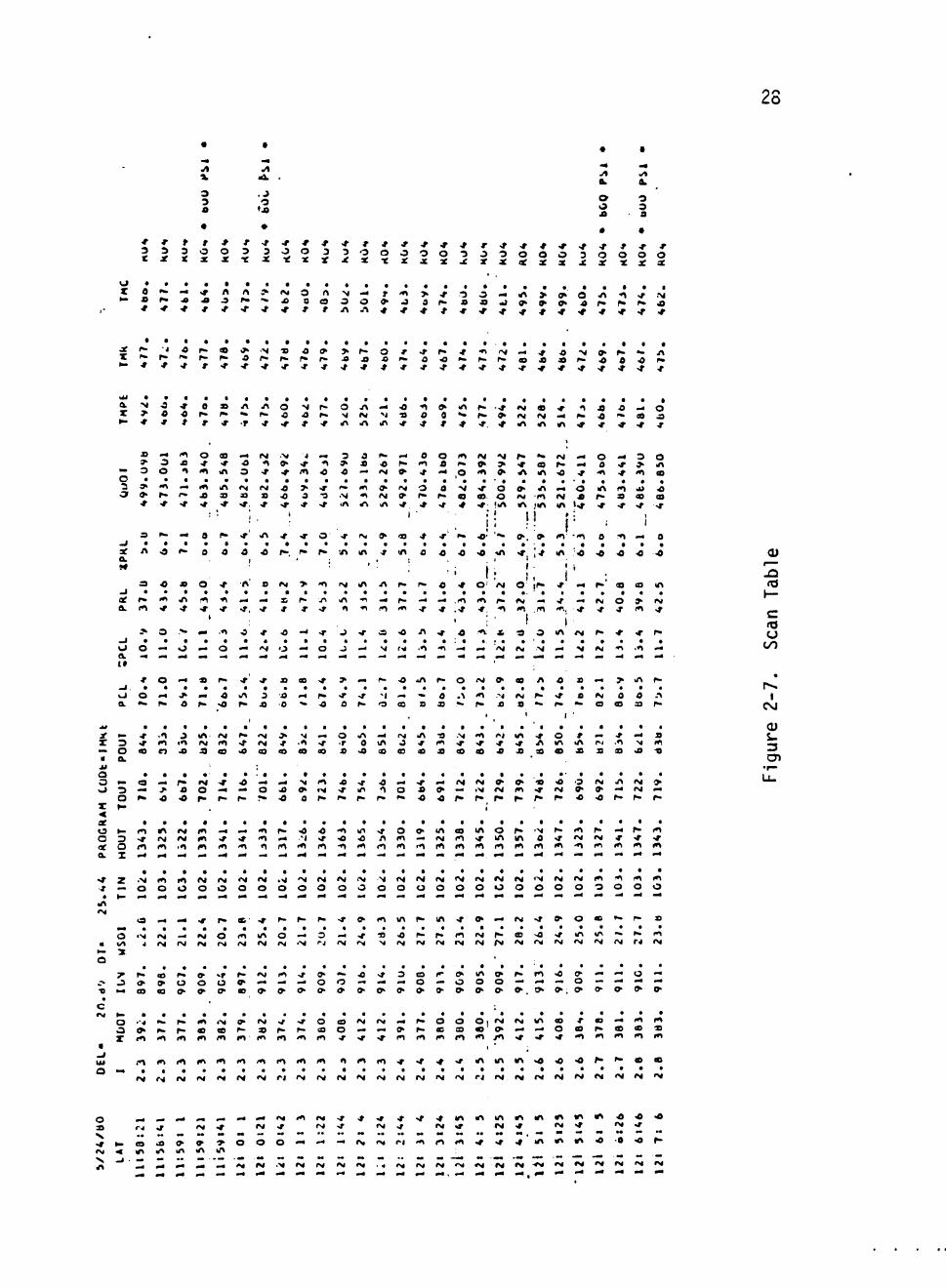
The Process Tape is used in various ways, depending upon the
requirements of the various data analysis programs. One of the uses
of the Process Tape is to make the Scan Tape, from which the Scan
Tables and Scan Figures are prepared. The Scan Tape stores data from
a few selected channels. The Scan Table records sixteen columns of
information, taken on the date of the table, which serve to give a
general picture of the nature of the system operation and performance
on that date. An example page from a Scan Table is shown in Figure
2-7.
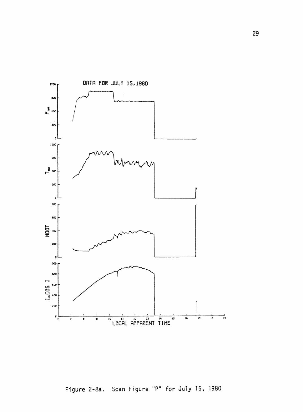
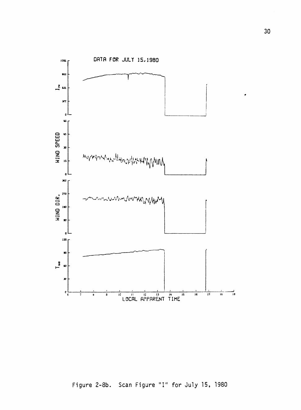
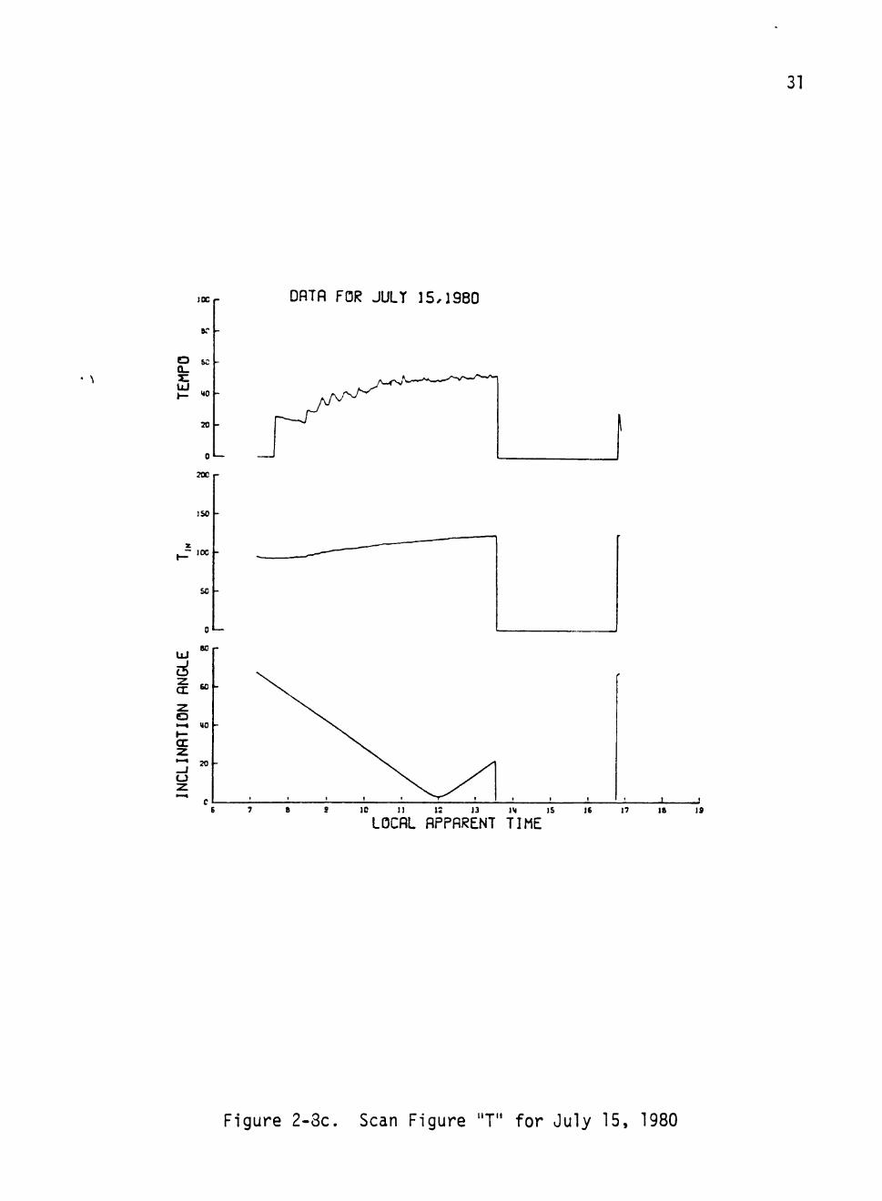
The Scan Figures are set of eleven computer-drawn curves given
on three pages:
"P": exit pressure, exit temperature, mass flow rate, and
projection of insolation onto the aperture normal.
"I": direct normal insolation, wind speed, wind direction,
and ambient temperature.
"T": TEMPO, inlet temperature, and inclination angle.
for each day. An example of the Scan Figures is given on the three
sheets of Figure 2-8. In order to reduce plotter times by a factor
of five, the data plotted is successive averages of five consecutive
time sample points. Thus, some smoothing (digital filtering) is pre
sent in the Scan Figures.
By convention, the value zero is plotted in the Scan Figures
over any period for which data is not available. During such periods,
either the system was not operated or the DAS failed, typically be
cause of some diskette recording problem.
28
a o
./I
o 3 a
3 3 3 O 0 3 3 0 0 3 3 O * •* * -r ^ T -t -t •* * -t ~r o o o X JC <r
o • . « r 0 »«- - « »• s r> «
•» -r * a t
N — > ••3
• r
3 — O 'A
< .f •o
J T f » a r-
a. r S A o
c •r
•o f o J> "*
rf> .A a^
* i n ^ • 0 - f . r • -r.
- f «v • * > rsi N • -<r iA <o ^ •r
« . d o ^ OO a * - f *
o 3 O
S - 4
>rt 3
IS* .-V J
•*» ^ . -r .*• <*>
^ z a "• -n > s « ^ « - • <M
-- o o »*» 0> 4' ^ O
rvi -" f-^ > -* • ^ * A l A - o
— o '^ 3 O •r 9- iTi
• «> « l A I N s a •r •*.
•o . 0 > ^r ' " m ^ (M O ^ -r o A . 4 O l A f ^ a>
. r ^ l A ^ i A ' ^ . # ^ 4 ' « ' ! < A I A } I A I A I ' ^ ^ ^ > ^ GO
a.
-J of a.
a
A o r»
- • a
0 •r « • -"n — 0
•o r- . f* 'O iA .» lA « <0 -O 'O -O
3
(*1
J^
o
* o #..
«
• *
3
—
O
. 4
f".
JO
- f
. .
o
• J»
o
o
t
^
-
s M
p .
•r
•r
••^
o
r»
4
.^
•A
•r.
•0
^*
•r' krt
1
o
• *
•r
I N
•r 3
A
<M
*
•0
o
s
'« • 0
>
•r
•
—
3>
. 4
^
*>
«*
•r
o
^ r» •a
(M
n
J
J
> ^ 0
lA
*1
V
• i .
, . -r ^ •
^
m
a
N
• f ~
•) •o
r»
1*S
•O
r^
• 0
« 4
I S
r»
-r
A
.<>
. A
-. S
«
*
>r • * >
p .
0 3)
•f
.•»
4
-
O
. ^
o
•r.
• ^
. M
<M
<
1
I M
-
X
«<
> ^4 a
o-
1 •a
»S|
a IM S
1
I f *
. I * *
3
N
A
^
*
m.
1 «A
-
c <*•
1
* 4
•>r
/ N
N
a
s
f "
-r
^ <M
» 4
l>«
e
«
*
• •n
> 0
e
lO
(
•* .«»
iA
4 a
lA
*
r»
0-M
r"
.•> r-
X
X <
4 1^ >'\ fv i*\ -t r4 * • * » o n A 2 a i a o 4 > < o
M O l A -rf •r -r O US CO S A A
lA .•X
•r a
<»» >r «
<»< * «
«A
•r X
-r A a
o I A S
r >A A
mm
r^i
s * •n a
1.4
•< .XI
0)
C/1
I CSJ
(1) &. 3
o — •a -* ^ ^ — o J> 9-f- r» 4 o
0 . ' ' r . ' I M I < 4 » » « 4 O < M A f ^ > 1 0 » * — • • ^ < M | W t ^ r M 9 > ^ - r f l M «
or o a of a
-*• • T
•A «M
« •—
a
^ 3 O z
y
n i/\ •X
m •*
• N
o
d
•• i
l A I N
«n o
^ 4
rvj
«N <X
i*» O
.^ r^
m C I
<M O
•* »W
« 4
•r
rs« O
?>•
o
v 4
•*
04
o
S '
(*»
•»> i n
• N
o
• *
l A
^ 0 ^
• 4
o
r-
o
•0 -1
• N
o
r-^
4 «f
fM
o
r»
O
<«% •o
f>^ O
•f
«M
lA •0
l>i
o
> ^
^ A
N
o
f\
•o
o m
«M O
(A
-0
* M M
t>i
o
r.
r-
l A • N
r>i O
IA
p .
« ("1
rx O
^ m
I A
>r
»M
o
» IM
o I A
( M O
« r-
• I A
«M O
IM
OD
• N 0
<N
o
«* >a
p-
•r
I N
o
o> ^
<* r«»
f V O
o l A
^ rx
1 ^ 3
s
(A
• M
T
•^
o
» . * •
r-• *
m o
^ p .
rt
m •r
ir\
O
s
m IM
•o «
•a
a ] o o 9- «>
P- OX rt >f 9 M _ . ^ e » » o
^ ~- « •.» 3 o o * . .^ ^ o ^ ^ o o*
eo I.- * lA O — O O » 9- O' O-
9 f r^ -O IT- » . - < o —
c «M
o 3 X
* p . p -^ ^ ^ <M ^ IM V a p- s ^ 1 ^ ^ • ^ rt
o I S
O IM IM .M O — -< »• ^ .X •* m
O o
i « «n
IM <M ws a> o > • ^ O
O - •
rA J IM ^ «M . f
O . S » » ' > 0 0 0
A <M r x I M «M
29
12K r
too
uc
xo
DflTfl FOR JULT 15,1980
0
1300 r
900 -
SCM -
300
0
BOO r
£00
2X -
'^V^-^^\/VA
.^
<fi o CJ
z •—^
000
800
6 X
Mon
r x
—
10 J! It J6 17 le IS
LOCAL flPPflRENT TIME
Figure 2-8a. Scan Figure "P" for July 15, 1980
1700 r
BOO -
J^\-30C -
0 —
S O r
O US -UJ UJ a. tn X -
a
3 >s -
o«— 360 r
770 -
a 180 -
90 -
0
170
30
DflTfl FOR JULT 15,1980
V ^ ' r ^ V % , y , l i ^ . ^ V ^ ^
•'M '^A'-iA/vv^/^^N^/^
J ! I I I
LOCAL fiPPRRENT TIME
30
t 5 IC n 17 13 1« IS IE 17 It 15
Figure 2-8b. Scan Figure "I" for July 15, 1980
31
IK r
O SC Q-
UJ MO
70 -
0
700
ISO
100
so
0 " —
80 UJ
>—I MO -
70 -
CJ
DflTfl FOR JULT 15,1980
1 0 11 13 13 IM IS
LOCflL flPPRRENT TIME It 17 IB 19
Figure 2-3c. Scan Figure "T" for July 15, 1980
SECTION III
PROCESS CONTROL ALGORITHM
3.1 Control Strategy
The ADVS process control is accomplished by the Bristol process
controller by regulating the feedwater (CV-01) and exit steam (CV-02)
valves. The Bristol, using the algorithms for each valve, sends analog
signals to the Montec actuator valves (CV-01 and CV-02) to maintain
relatively constant exit temperature and pressure. The exit steam
valve tries to maintain constant exit pressure, while the feedwater
valve regulates the flow in a manner to maintain constant exit temper
ature. This section deals with the development of algorithms for the
feedwater valve.
3.2 Control Algorithm for the Feedwater Valve
In order to avoid the problems encountered in implementing various
control algorithm (ref. Sec. 2.2), it was necessary to take an in depth
look at the factors effecting exit temperature. Exit temperature is
directly related to the energy captured by the fluid, which in turn
depends upon the available energy captured by the bowl and the loss
of energy due to radiation and convection. There are numerous factors
involved here. For example, the direct normal insolation (IQ»^) is the
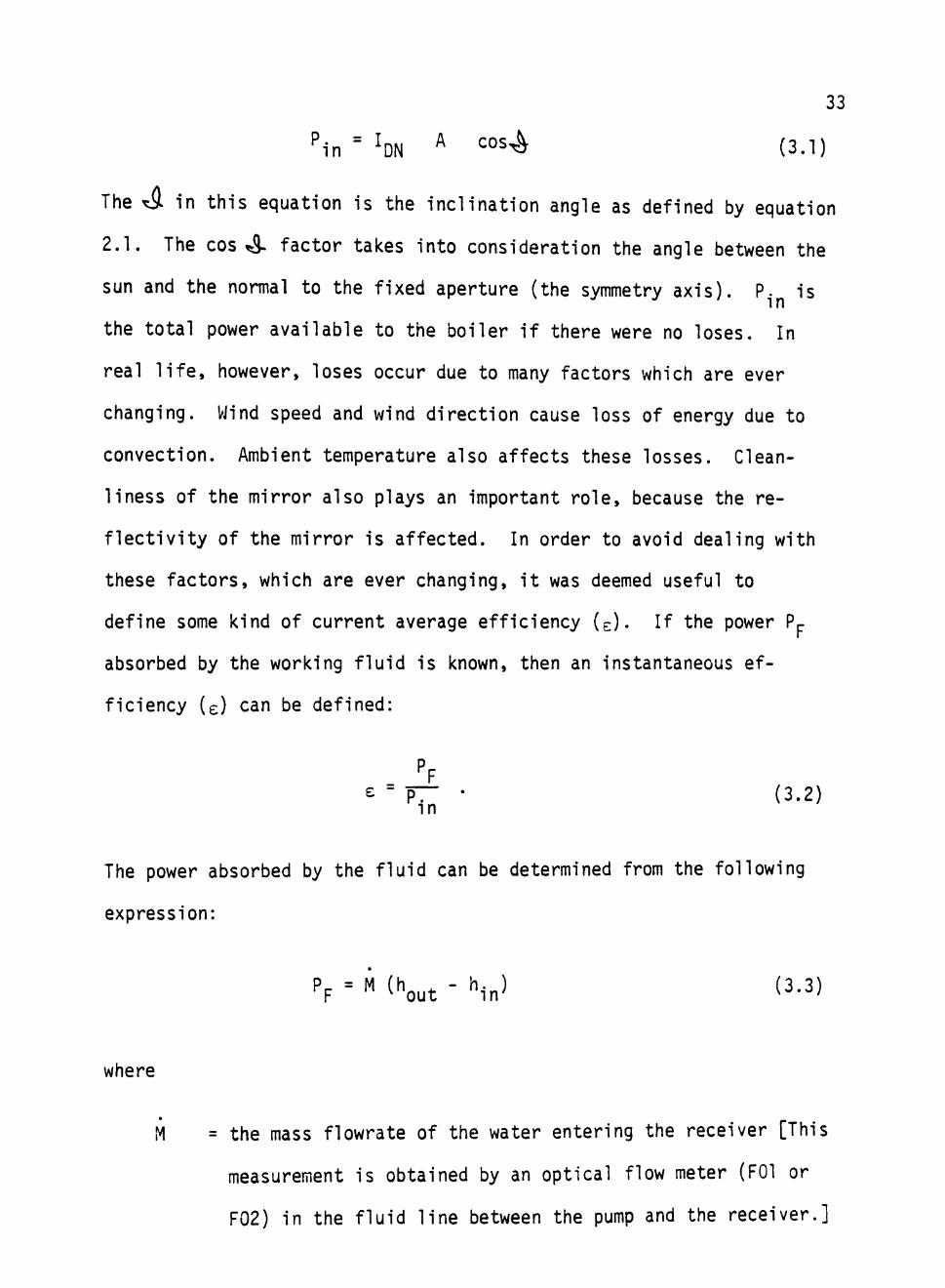
factor related to energy capture. The available input power (P.j ) is
determined from the direct normal insolation (Ipj ) on the aperture area
(A) of the bowl:
32
33
^•n = ^DN ^ ^ ° ^ ^ (3.1)
The Ty. in this equation is the inclination angle as defined by equation
2.1. The cos 4- factor takes into consideration the angle between the
sun and the normal to the fixed aperture (the symmetry axis). P. is in
the total power available to the boiler if there were no loses. In
real life, however, loses occur due to many factors which are ever
changing. Wind speed and wind direction cause loss of energy due to
convection. Ambient temperature also affects these losses. Clean
liness of the mirror also plays an important role, because the re
flectivity of the mirror is affected. In order to avoid dealing with
these factors, which are ever changing, it was deemed useful to
define some kind of current average efficiency (e). If the power Pp
absorbed by the working fluid is known, then an instantaneous ef
ficiency (e) can be defined:
P - • (3.2)
The power absorbed by the fluid can be determined from the following
expression:
p p ' " ^^ut - '"J (3.3)
where
M = the mass flowrate of the water entering the receiver [This
measurement is obtained by an optical flow meter (FOl or
F02) in the fluid line between the pump and the receiver.]
34
^out ^ ^^^ enthalpy per pound of the fluid exiting the receiver.
h.j^ = the enthalpy per pound of the water entering the receiver.
Now, in order to define a current average efficiency <e>, the
current average input power (P,-..) and the current average power absorbed
by the fiuid (Pp) may be used. The current average input power (P,--.)
can be defined as follows:
^in = <^DN> ^ ^ ° ' ^ ^ - ^
where
<Ipjl > = some kind of average of I j over a small
time period.
The current average power absorbed by the fluid (Pp) can be defined as:
Pp = <A> [h(T„„^) - h(T.„)] (3.5)
where
<M> = average flow rate over a small time period
T ^ = time average of T ., . over a small time period out ^ out
h(T) = specific enthalpy. [The pressure is considered constant
for simplicity.]
The current average efficiency is defined to be:
<"> [ 1 ( W - ' ( in) (3.6)
<IDN^ACOS^
35
This current average efficiency accounts for factors such as wind speed,
wind direction, ambient temperature, cleanliness of the mirror, and
many others. The flowrate M required to obtain the desired temperature
T^ can then be estimated:
^DN ^ ° ^ ^ = Ml,) - h(T.„)J ^ • (3.7)
Substituting the current average efficiency into this equation and re
arranging, one gets:
<M> ^DN "^'S' "^'in
The right side of this equation identifies a useful variable combina
tion which can be used to define an "error":
JpN ^(^out^ - ' < in) = 1 - S . (3.9) <l0N> h(Ts) - h(T.„)
where the quantity so defined will be called the "error".
Now, if V, CVCl, is the command voltage to the inlet valve, one
might presume a linear relationship between V and M, and proceed as if
M = e (V^ - V) (3.10)
where Vp is an (out of range, V < V^) "cut off command" at which M = 0,
and 3 is a constant (slope of the line). It would then follow that
36
<f^ = 6 (V^ - <V>) (3.11)
and, consequently.
; ; ^ - V ^ w =1 - ^ (3.12)
Solving for command voltage V, one gets the fo rm
V = <V> + [V(. - < V > ] ^ (3.13)
This equation is no more than a peculiar, approximate statement
of conservation of energy, but it is suitable for trial as the con
troller algorithm. The command voltage V is clipped to never be sent
out negative or larger than a maximum value V which corresponds to a
near-zero flow rate, M * 0. The parameter V is chosen "out of
range" ; i.e., V , > V ^ so that V^ - <V> > 0. [In practice, V^ can be
made a function of V related to the slope of an M vs V curve.] The
average, <V>, of the value of the command voltage is defined with
a limited memory (further discussion in next section). The term
is such that it vanishes at steady-state set-point conditions.
The controller was given a "hand-latching" characteristic in that
the averaging operation does not function when the controller is in
Manual mode, but automatically starts with an initial value of <V>
equal to the V in effect at the instant that the operator switches to
Active Mode. In other words, if the operator assumes manual control
at any time, as soon as he returns control to Active, then Active
will latch-on and start from wherever the operator left the valve.
37
If the operator happened to leave the valve in a steady state at the
desired set-point ( g = 0 ) , then the Active controller will make no
changes as long as "£ remains zero.
The controller is also free of bias in that if ^ vanishes, then
V = <V> and the valve is (and has been) at the correct setting for the
fluid set-point. This algorithm is adaptive in that it will still
perform properly even if a hand-valve set-point is changed at the load
skid. Also, since conservation of energy was used, this controller
should not ever turn the valve the wrong way, even in the presence
of the nonlinearities. The expression for ^ can be simplified by
approximating a steam table at 1000 psia: (3.14)
t =!-< I... \ DN
^ D N "
| ^ ( W - ^'i.A . . [ DN iTout ' 1636°F\ jpr(Tirn^lT7;T - 1 -i < V r s "1636°F
The average <InM> of the direct normal insolation, is defined in the
same fashion as <V>. The set-point temperature is T^; output or exit
temperature is T .; and T. is the feedwater inlet temperature. The
active term shown in the expression above is bilinear in l^^ and T,
but under steady insolation is equivalent to K(T - T ^ ) .
3.3 Time -Averaging for the Controller
The control algorithm motivated in the preceeding subsection is
V = <V> + [V. - <V>] Z » (3-15)
where V is the command voltage for the inlet valve (V =0% gives wide
open valve, V = ]Q0% give minimum flow) and is the error:
38
t =1 -/ Inf.. \ /T..... + 1636°F \ "DN 'out
\
^DN> r S "• ^^36°F (3.16)
The command voltage is automatically clipped by the Bristol to always
lie in the range 0 - 100%, and the hand-latching procedure requires
that it be possible to reinitialize the averages <\i> and <lr,K,> quickly
and easily. The responsiveness and adaptability characteristics of the
controller are dependent upon the method of averaging, a type of ex
ponential memory loss is desirable for the averages.
Due to calculator limitations in the Bristol computer, averaging
with an exponential weight is most easily accomplished by using an
analog approach. Considering the analog averaging circuit shown in
Figure 3-1, one gets by inspection:
d <V> dt
The solution of this differential equation.
= A = G (V - <V>) . (3.17)
IS
^ <V> + G <V> = GV , (3.18) at
t
<V>= e- (t - V <V> . G I e-S(t-t')V(f)dt"''-'''
^0
where t is the time of initialization (or of the most recent reini-0
tialization). The gain G in the analog circuit defines the reciprocal
of the "exponentional memory loss time" or "forgetting time":
E
u o II
<
4-> < ]
J O
A > « V
Q .
+J
3
A
V
I
39
' \ \ \ \ \ \ \ \ \ \ ^
s-<_)
01 a» <o s . O)
>
en o <o c <
I en
i-3
40
^M • ^
1 G * (3.20)
The nature of the <V> defined above as an averager can be re
cognized by considering <V> for the special case that V(t) is constant:
<V>
V = V.
-_e-G(^- ^o) < V > . [ 1 - e-^(^ -^oh V^ . (3.21)
One notices that the average develops smoothly from the initialization
value, <V>Q, to the long-time average, V , with an exponential time
scale of TM- Thus the past is damped out and the "average" is de-
fined with a limited memory depending upon the analog gain factor G.
The Bristol is a digital computer, and the command servicing
cycle time used is At = 0.8 sec. Thus, the actual implementation of
the analog averaging equation
^ ^ = G [V - <V>] (3.22)
proceeds recursivsly as indicated in Figure 3-2:
(3.23)
= GV^ + (1 - G) <V>^
where
G E GAt = G (0.8 sec) , (3-24)
and the subscript indicates the time step. The hand-latching feature
41
A
V
o h—
— I «=c < : Qi I— o I—I LU •—' ^Z Q •—I
A
V
I
>
(Si
ex: o
_ J
CJ
o to
•p—
CQ
&-(U
> «3:
•t->
•r" cn o
c o
•r-4J «TJ
-t-> C <u E (U
Q . E
CM I
CO
i-3 cn
CJ A
V
42
for reinitialization is easily accomplished by setti ng
< % = Vo '
so that
<v>^ = <v>, = v^ ,
<V>2 = GV^ + (1 - G) <V^> = GV^ + (1 - G) V^
<V>3 = GV2 + (1 - G) GV^ + (1 - G)^ VQ ,
and so forth:
n - 1
<V>, , T = G 2 (1 - G)^ V^ . M l - G)" V^ . (3.25) r = 0
The sum of the weights is one, so that an average is obtained with
recent values of V weighted more heavily, provided only that
G <i 1 ; i.e., T| > At = 0.8 sec.
The role of G is wery important. If G = 1, then
T . E - E ~ = t = 0.8 sec, and • G G
<V>n . 1 = ^ '
so that the averager would act with zero averaging interval and no
memory. At the other extreme, if G = 0, then "iv; = °° » "
43
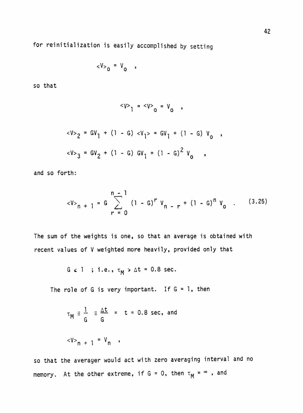
SO that the average would be pinned at the initial signal value.
Intermediate values of G, corresponding to T^ = 26.7 sec, 53.3 sec,
and 80*.0 sec are illustrated in Figure 3-3. For these examples the
average was initialized at <V>Q = 0% and the signal value was given
as step change (rise time < 0.8 sec) to a constant value of 100%.
Notice that the average rises from 0% to closely approximate
100 (1 - ^) = 63.2%
in the time T^..
The controller algorithm developed in this section has been suc
cessfully employed for the ADVS and has been in service for nineteen
months. Although the service has been satisfactory for the most part,
improvements are definitely possible. Simulation of this controller
is considered in the next section.
44
i i
woot
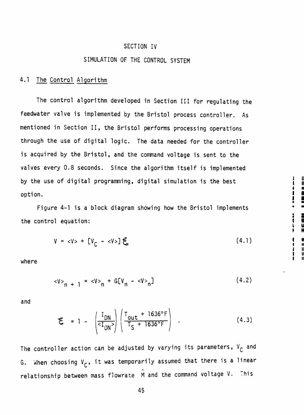
SECTION IV
SIMULATION OF THE CONTROL SYSTEM
4.1 The Control Algorithm
The control algorithm developed in Section III for regulating the
feedwater valve is implemented by the Bristol process controller. As
mentioned in Section II, the Bristol performs processing operations
through the use of digital logic. The data needed for the controller
is acquired by the Bristol, and the command voltage is sent to the
valves e^ery 0.8 seconds. Since the algorithm itself is implemented
by the use of digital programming, digital simulation is the best
option.
Figure 4-1 is a block diagram showing how the Bristol implements
the control equation:
V = <v> + [V. - < V > ] ^ (4.1)
where
<V>n . 1 = <'\ * StV„ - <V>„] (4.2)
and
-£ = 1 -/ I DN
\
<^DN>'
T . + 1636°F\ out T^ + 1636°F
(4.3)
The controller action can be adjusted by varying its parameters, V . and
G. When choosing V^, it was temporarily assumed that there is a linear
relationship between mass flowraie M and the command voltage V. This
45
46
c o
<u E o.
3
O
o
ItJ & -O l <T3
9
o o
CO
I * ^
0) s . 3
Y V
47
is only approximately true. Also, since there are numerous hand-
operated valves on the load skid which are occasionally reset, and
since the pressure compensating valve is erratic, the relationship
between M and V . changes from day to day. The value of V^ was chosen • L
out-of-range, such that V , is greater than V . [The range of V is
from 0 to 100%, where V = 0 means the valve is completely open and
V = 100% gives minimum flow; M - 0.] In practice, a value between
101 and 115 was usually assigned for V^. The memory time for aver
aging |v| = (0.8 sec)/G, was selected by trial and error. In practice,
a value of G between .01 and .03 was used, depending on the type of
insolation pattern observed for the day. One should also note that
the term [V . - <V>] in the control equation (4.1) is merely a variable
gain factor. If the system is in steady state, (V . - <V>) is simply
a constant.
4.2 Strategy for Simulator Development
In order to explore the control equation, it was decided to simu
late the control system and then vary parameters (in the simulation
model) to see the impact on the system behavior. There are two major
obstacles in accomplishing this task. One of the problems is related
to the data storage system. As mentioned in Section II the data
acquisition system (DAS) stores data for later use. Although the
data is conveniently stored, it is only sampled every 20 seconds
during the ADVS operation. On the other hand, the Bristol process
controller receives data and computes the command voltages every 0.8
seconds.
48
The second problem deals with the prediction of exit temperature.
In the actual control system, when a command voltage is sent out, it
regulates the flow in the receiver, producing an exit temperature
which is sensed by a thermocouple. The exit temperature is then
utilized in the next calculation of command voltage. In order to ac
complish this feature in the simulation, it is essential to establish
a mathematical model to predict exit temperature for any command volt
age.
The task of simulation is divided into two phases. Phase one of
the simulation consists in building a test computer model which can
predict command voltage from the same information available to the
Bristol process controller. If the command voltage produced by the
computer model can be made to agree with the actual command voltage
sent out by the Bristol for a reasonable period of time, one can con
clude that the computer model is capable of simulating the control
system.
The second phase constitutes of building a model that can predict
exit temperature given a command voltage. This model can then be
combined with the first computer model to provide a completely in
dependent simulation model. Once an independent model is built, it
can be used for general testing and development purposes.
4.3 Computer Simulation Model I
The function of the Computer Simulation Model I is to predict the
command voltage based on the information available every 20 seconds.
Essentially, this model receives the same type of input data as the
49
Bristol process controller. The frequency of data received is dif
ferent, though. The Bristol receives data every 0.8 seconds and com
putes the command voltage. On the other hand, the model receives data
every 20 seconds (i.e., 25 times less often than the Bristol). Since
the TQ^.J. is dependent on when the command voltage is sent out, it is
difficult for this model to predict command voltages similar to that
predicted by the Bristol. Therefore, it is considered reasonable if
this model can follow the actual commands for one hour. [The averaging
circuit has memory of a few minutes.]
In order to accomplish this task, it is important that the aver
aging circuit model follow the actual averaging circuit. A modified G,
denoted as Gj, must be defined for the simulation such that
<V> = <V> + G(V - <V>) for calculation iteration every 0.8 seconds
(4.4a)
and
<V> = <V> + G,(V - <V>) for calculation iteration (4.4b) " every 20 seconds
follow the same path. Curves for several values of G are shown in
Section III. It was necessary to develop a relationship between G and
G, such that they follow essentially the same curve, in spite of the J
time step size difference in the calculations. From the above equation
one can directly deduce that when G = 0, then Gj is also zero.
As a first approximation, one can relate the two gains by re
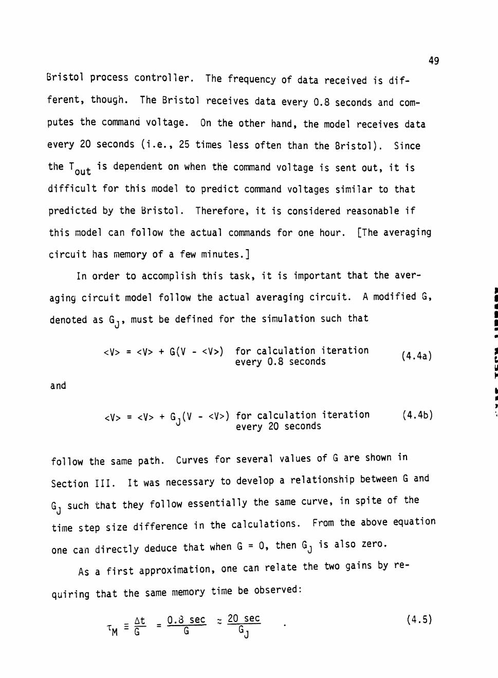
quiring that the same memory time be observed:
^ At _ 0.3 sec z 20 sec (4.5) ' M - G G G.i
50
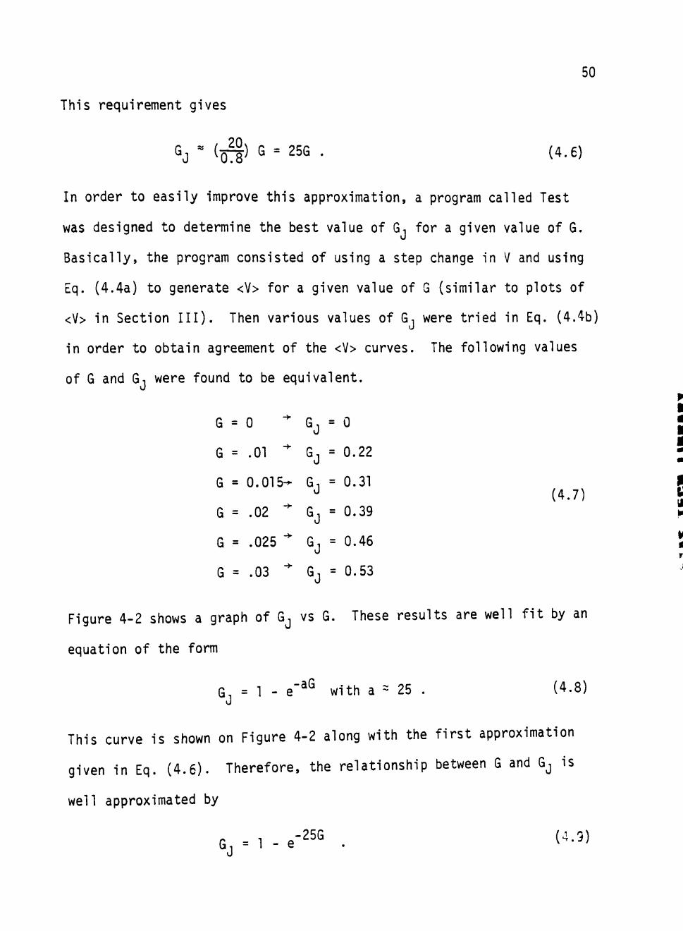
This requirement gives
^J ' ^ O ' = 25G . (4.6)
In order to easily improve this approximation, a program called Test
was designed to determine the best value of Gj for a given value of G.
Basically, the program consisted of using a step change in V and using
Eq. (4.4a) to generate <V> for a given value of G (similar to plots of
<V> in Section III). Then various values of G. were tried in Eq. (4.4b)
in order to obtain agreement of the <V> curves. The following values
of G and G, were found to be equivalent.
G = 0
G = .01 ^
G = 0.015-
G = .02 "
G = .025 ^
G = .03 ^
GJ = 0
GJ = 0.22
GJ = 0.31
GJ = 0.39
GJ = 0.46
GJ = 0.53
(4.7)
Figure 4-2 shows a graph of Gj vs G. These results are well fit by an
equation of the form
G = 1 - e"^^ with a = 25 . (4.8) J
This curve is shown on Figure 4-2 along with the f i rs t approximation
given in Eq. (4 .6) . Therefore, the relationship between G and Gj is
well approximated by
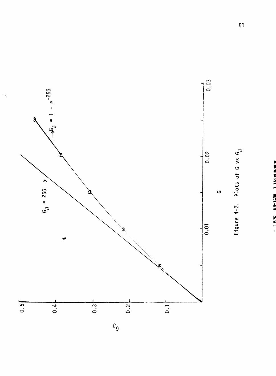
51
CO - I o
CVJ o
• o
CD
— o
• o
^ C3
CO >
CI5
<4-O
to +J o r—
a.
• CsJ
1 ^ (U s. 3 cn
•r— Lu
p
I
2i
U A
/I
52
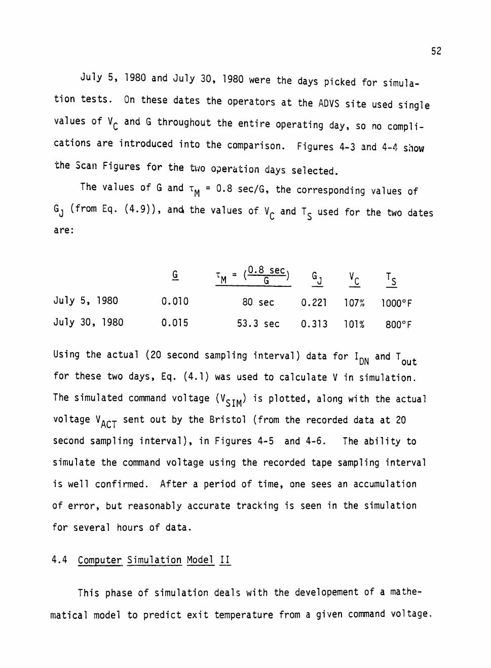
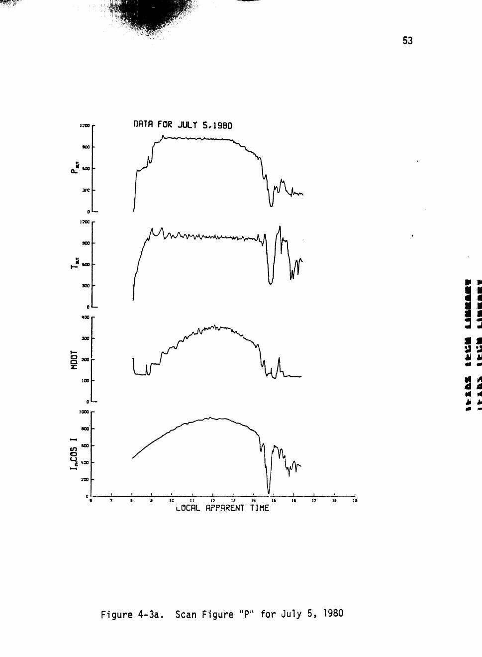
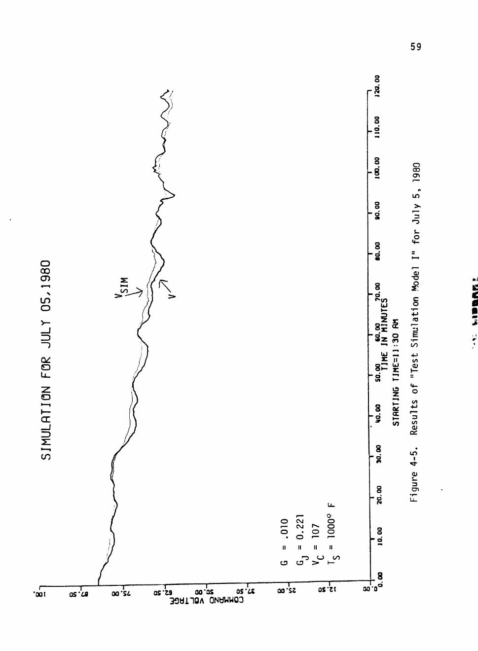
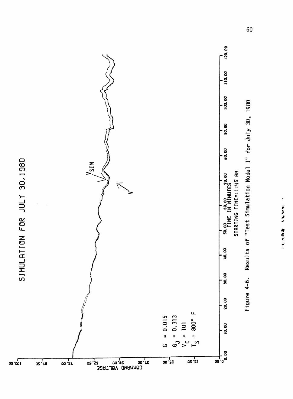
July 5, 1980 and July 30, 1980 were the days picked for simula
tion tests. On these dates the operators at the ADVS site used single
values of V . and G throughout the entire operating day, so no compli
cations are introduced into the comparison. Figures 4-3 and 4-4 show
the Scan Figures for the two operation days selected.
The values of G and x^ = 0.8 sec/G, the corresponding values of
GJ (from Eq. (4.9)), anci the values of V^ and T^ used for the two dates
are:
Q
0.010
0.015
^ _ /0.8 sec\ M ^ G ^
80 sec
53.3 sec
!J
0.221
0.313
!c
107%
101%
Is 1000°F
800° F
July 5, 1980
July 30, 1980
Using the actual (20 second sampling interval) data for 1 , and T
for these two days, Eq. (4.1) was used to calculate V in simulation.
The simulated command voltage (V^r^) is plotted, along with the actual
voltage V p-j- sent out by the Bristol (from the recorded data at 20
second sampling interval), in Figures 4-5 and 4-6. The ability to
simulate the command voltage using the recorded tape sampling interval
is well confirmed. After a period of time, one sees an accumulation
of error, but reasonably accurate tracking is seen in the simulation
for several hours of data.
4.4 Computer Simulation Model U_
This phase of simulation deals with the developement of a mathe
matical model to predict exit temperature from a given command voltage.
mwwz
53
1700
•00 -
uo -
arc -
0
170C
SOO -
* B O o l -
300 -
0
MOOr
30D
TOOr
JOO -
DflTfl FOR JULT 5.1980
IC II 1! 13 IM IS
LOCflL APPARENT TIME 19
Figure 4-3a. Scan Figure "P" for July 5, 1980
liOCr
»oc -
too
JOC -
u
a MS
lO
IS -
c
K O r
270
a a IBS -
X -
0 1 —
i r o r
i ST-
30 -
DflTfl FOR JULT 5,1990
'' .AMMrt^^^^^W iV
/ ^ *Y -^ \
• I I
E 7 t 9 IC 1 ! i ; IJ ]M 15 }S 17 IE IS
LOCflL APPARENT TIME
54
Figure 4-3b. Scan Figure "I" for July 5, 1980
55
IOC
a. UJ
Mr
JC -
0
roc r
:se -
w-T " * •
SC -
DflTfl FOR JULT 5,1980
LOCflL APPARENT TIME
Figure 4-3c. Scan Figure "T" for July 5, 1980
56
17S0 DflTfl FOR JULT 30,1980
BX
bOC
3K -
"AT 1 ^
*'>^^'v/\^\/A/\/
B
<
LOCAL APPARENT TIME
Figure 4-4a. Scan Figure "P" for July 30, 1980
17K
soc
600
XX -
D I—
UJ UJ
cn 3,
IS -
0
35C
rTo
a o 2
9C -
c
120
90 -
i
DflTfl FOR JULT 30,1980
-'^'''^'•'''tMi^
- ^ . - . ^ v . . . « V . , , U
W
m'^^hf^'^^
IC
LOCflL APPARENT TIME
f ^ ^
1 I ' 1
1
i 1 1
) ( 1
\
1 ( t
!
1
II* IS IE 17 «
57
Figure 4-4b. Scan Figure "I" for July 30, 1980
58
DflTfl FOR JULT 30,1980
10 11 i : 13 IK I S
LOCflL APPARENT TIME
Figure 4-4c. Scan Figure "T" for July 30, 1980
59
V
o o
k8
o o
o 00 CD
LO O
OO 3 - ^ ( ^
O
O
CE
o o o
o a
s o
o 00
in
3
S-O
CO
s d «^<n
UJ t—
i •
« a Z "^ UJ s:
S. d in
8 •
o 9
8 d
£ O (n
«>i«
I I UI S •—1
^-
z •-<
cc h-W)
(1) • a o z: c o
•^
ula
t
E •^ OO
4-> «/»
1— ~ M-. O
10 •M ^ • *
3 R
es
• i n
1
gure
4
o o . • II
CM C\J
o II
o
a o o o
cu c: <_} 00
I— '001
— I — 05*68 00'S^.
—r 1 r r-OS'33 00*05 OS'a 00 "52
33tii10A QNdWWOO
OS'Zt
o
a a
8 00*0°
S • • i
J
60
o 00
o cn
CE _J 3
i n CO
o < <— o . o o
o o »— CO
II II
- 3 O CD
II II
o OO
0Q*0O[ 0 5 ' ^ oa*S£ T — I r—
os'za 00*15 os' s 3 3 b : i O A QNdWW03
T 00'sz
— T " 05*21
a CM
8
S 8
3
o 00
O CO
o at
o o d 09
O
• « <n
Ui i—
§ 0 « - i
ox: d S z
*"•
Ui x:
8 ^ • o
8 d 9
8 •
o
o o
71 (X
tn 3 * •-.-^
II UI
z: •—1
K -
o z
a: 1—
-^ 3
O t -
t—1
o s c o •r-
(O
3 E
OO
0) 1—
O in
^ • ^
3 CO 0)
CI
1
3
cn o
!30*Q
61
The power absorbed by the fluid (Pp) is defined by (ref. Section III):
Pp = M l^^ut - N'n^ (4.10)
^ ^out ^^" ^^ determined, then steam tables and values of the exit
pressure P^^^ can be used to find the exit temperature T^. In order
to find h^^^ from Eq. (4.10), h.^, M, and Pp must be known. Calcula
tion of h . is very simple. The inlet temperature and pressure are
known. Therefore, h^^ can be found from steam tables. Thus, the main
task consists of finding M and Pp.
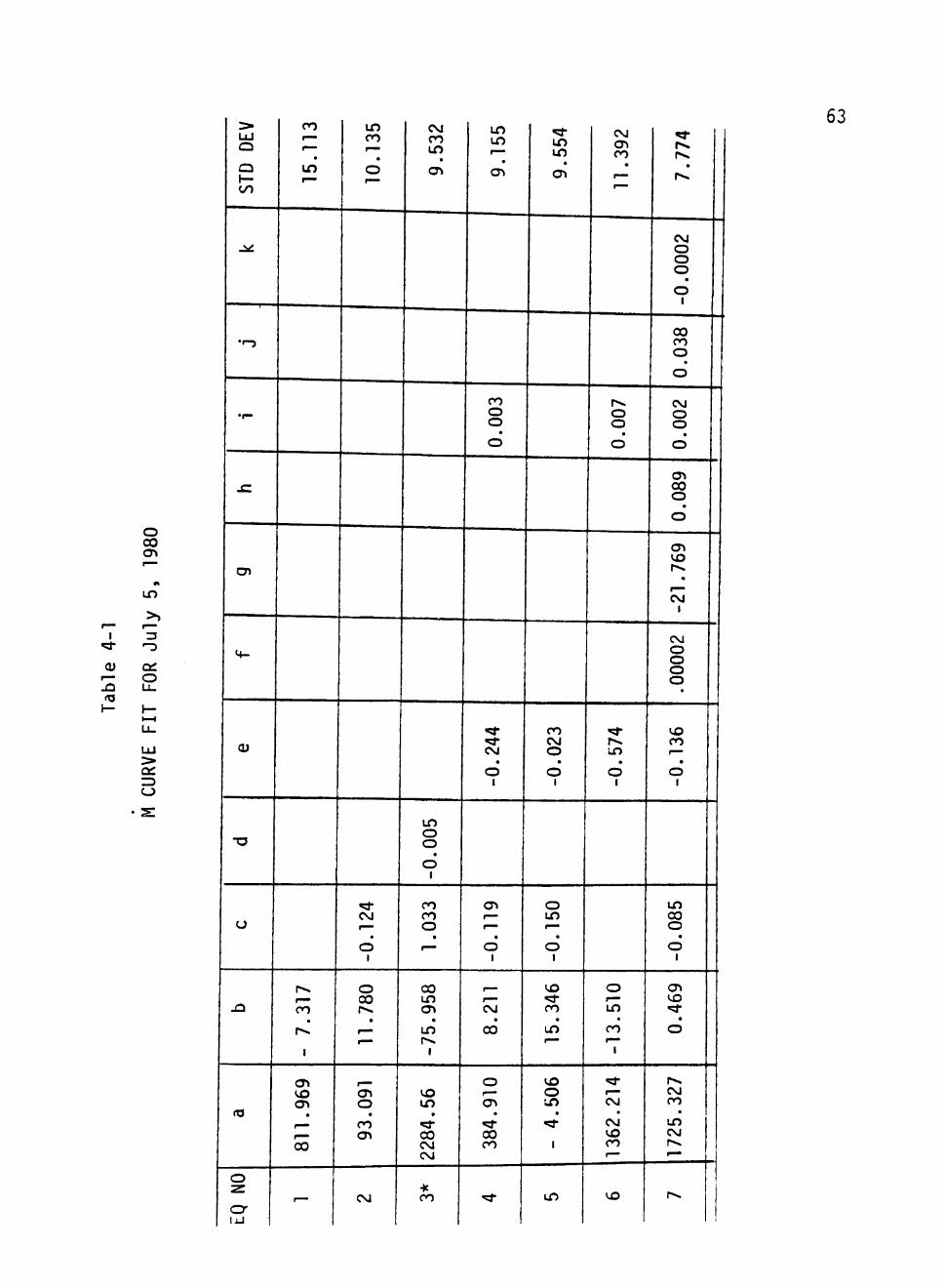
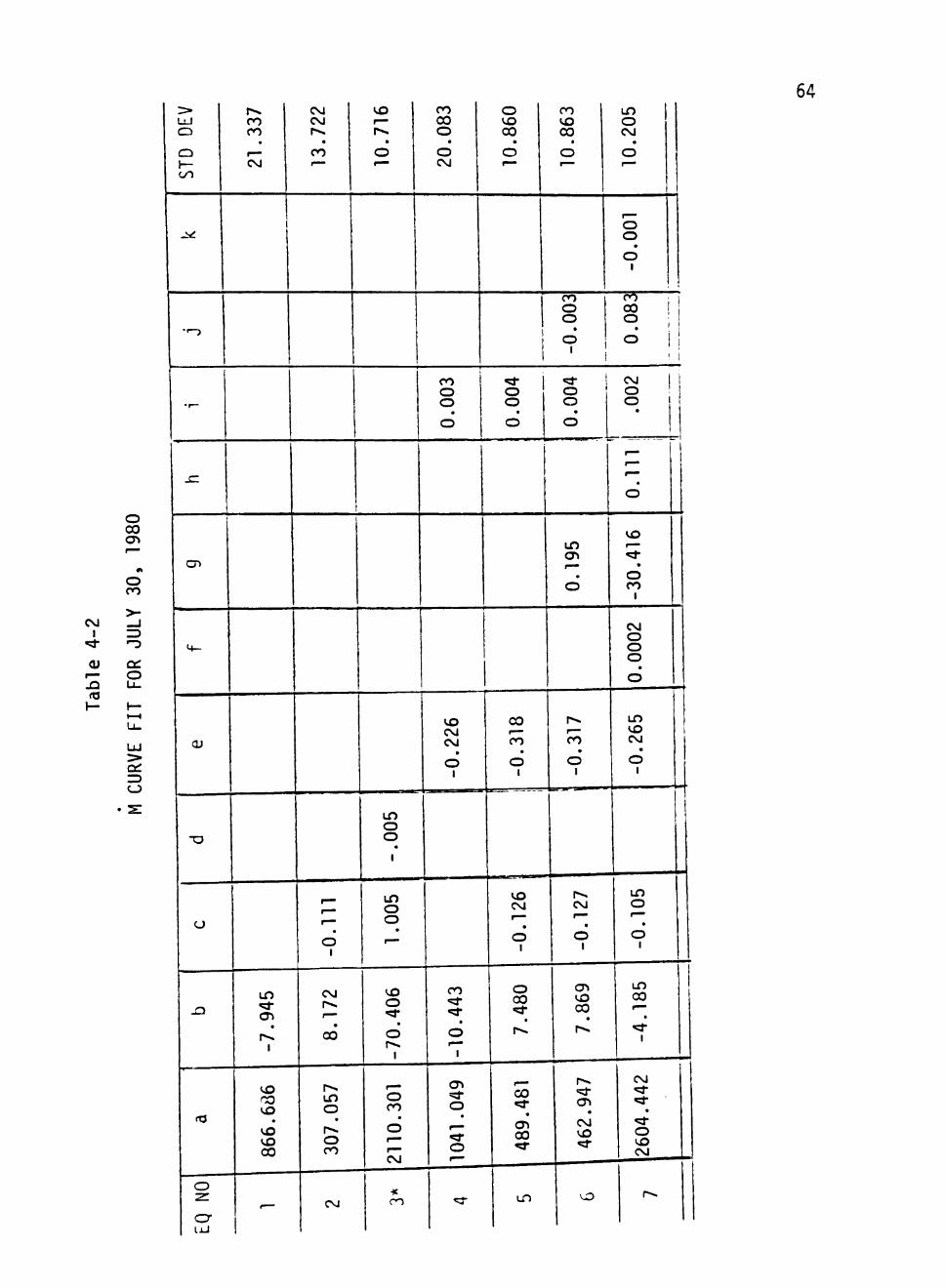
4.4.1 Mass Flowrate (M) Curve Fit
Since the mass flow and the Bristol command voltage are both re
corded data, it is possible to determine the relationship between the
two. The Statistical Analysis System (SAS) package was used for the
curve fit (ref. SAS language). SAS's statistical capabilities are
highlighted by its versatile least squares procedures, which produces
a wide variety of linear and non-linear regression analysis, analysis
of variance and covariance, and multivariate analysis of variance.
The GLM procedure, which uses the principal of least squares to fit
a fixed-effects linear model to virtually any type of data, was used
for the curve fit. Appendix A shows the program used for this curve
fit. It also shows the output of the curve fit. Equations of the
form:
M = a + bV + cV^ + dV^ + eP + fP^ + gT + hT^ +iVP + jVT + kPT
were tried, where a, b, c, d, e, f, g, h, i, j, k are constant and
62
M = mass flow rate, in Ib/hr
V = command voltage, in %
T = inlet temperature, in °F
P = inlet pressure, in psi.
Table 4-1 shows the combinations of these parameters with their re
spective standard deviations for July 5th. Since there are numerous
other variables (e.g., hand valves at the load skid), these curve fits
for M are only valid for that day. Table 4-2 shows the parameters of
the curve fits for July 5th. As can be seen from these two tables,
the coefficients are quite different from day to day.
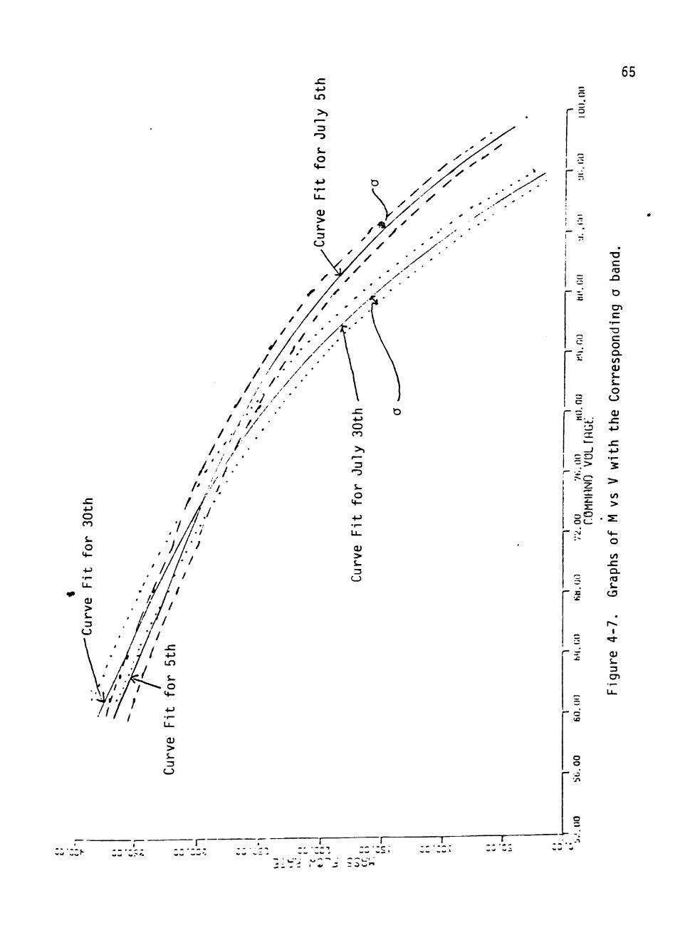
The curve fits marked with asterisks in Tables 4-1 and 4-2 are
those actually used for the simulations. Figure 4-6 shows graphs of
the curve fits used for the two dates, along with the corresponding
"one a" bands; i.e., M ± a, where a is the RMS deviation of the curve
from the data. The different curves used for the two days are seen
to be similar enough that their differences are not s^vy significant
statistically.
4.4.2 Calculation of Pp
A computer model TFAP was developed in 1977-78 by Dr. Clements
and H. Shankar to predict Pp given M, \^^^ V , and Q> . In 1978 Dr.
John D. Reichert developed a curve fit to results from the computer
model TFAP. The curve fit is known as TMR and is quite suitable for
use in computing Pp. The curve fit TMR is presented in Appendix B
(ref. SC).
r— 1
«!:^
OJ r—
.a <T3
o 00 <y\ '—
0t
i n
> ) 1 — •
3 "-o Q :
o u.
a:
s:
STD DEV
.2^
•>-}
•r—
. C
cn
M-
OJ
-a
o
J 3
(T3
EQ NO
15.113
- 7.317
811.969
-
10.135
-0.124
11.7
80
93.091
CM
9.532
-0.005
1.033
-75.958
2284.56
CO
9.155
0.003
-0.244
-0.1
19
8.21
1 384.910
^
9.554
-0.023
-0.150
15.346
- 4.506
i n
11.392
0.007
-0.574
-13.510
1362.214
vo
7.774
-0.0002
0.038
0.002
0.089
-21.769
.00002
-0.136
-0.085
0.469
1725
.327
r>.
63
64
CM I
CU
.a
o 00 cn
o CO
cti o
C_>
STD DEV
.KJ
""-
• r -
sz
cn
M-
OJ
-o
<J
- Q
<T3
EQ NO
21.337
1
-7.945
866.686
-
13.7
22
i
1
-0.1
11
8.17
2 307.057
CM
10.7
16
-.005
1.005
-70.406
2110
.301
*
20.083
0.003
-0.226
-10.443
1041.049
^r
10.860
10.863
-0.003
0.004
-0.318
-0.126
7.480
489.481
L D
0.004
0.195
-0.317
-0.127
7.869
462.947
vT)
10.205
-0.001
0.083
.002
• o
-30.416
0.0002
-0.265
-0.105
-4.185
2604.442
r-»
4-> in
65
> S-3
C_)
I _
i
cn
c o o. to
&.
o
di
- I -)-»
S: 10 ^ >
=~ O
m a.
S t 3
o 10
o o
p** I
3
cn
' J
'CCf-I
• - - ^ :c:s; ^ ^ ' o ' : Ow"^
66
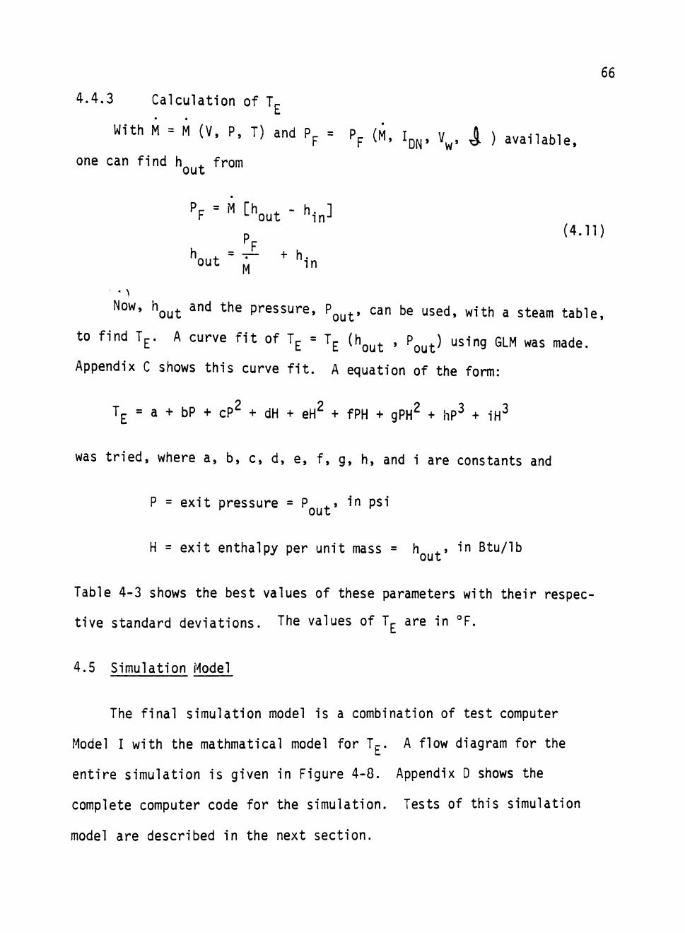
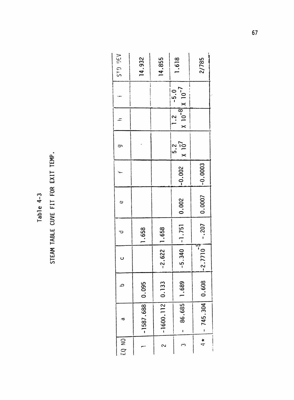
4.4.3 Calculation of T^
With M = M (V, P, T) and Pp = Pp (M, I ^ , v^, ^ ) ,,,,,,,,^^
one can find h . from
P = M [h . - h. 1 F •- out in-'
p (4.11)
Now, h^^^ and the pressure, P^^^, can be used, with a steam table,
to find Tp. A curve fit of T^ = Tp (h ^ ^ , P^^^) using GLM was made.
Appendix C shows this curve fit. A equation of the form:
T^ = a + bP + cP^ + dH + eH^ + fPH + gPH^ + hP" + iH^
was tried, where a, b, c, d, e, f, g, h, and i are constants and
P = exit pressure = P^ . » in psi • out
H = exit enthalpy per unit mass = h ,.» in Btu/lb out
Table 4-3 shows the best values of these parameters with their respec
tive standard deviations. The values of Tp are in °F.
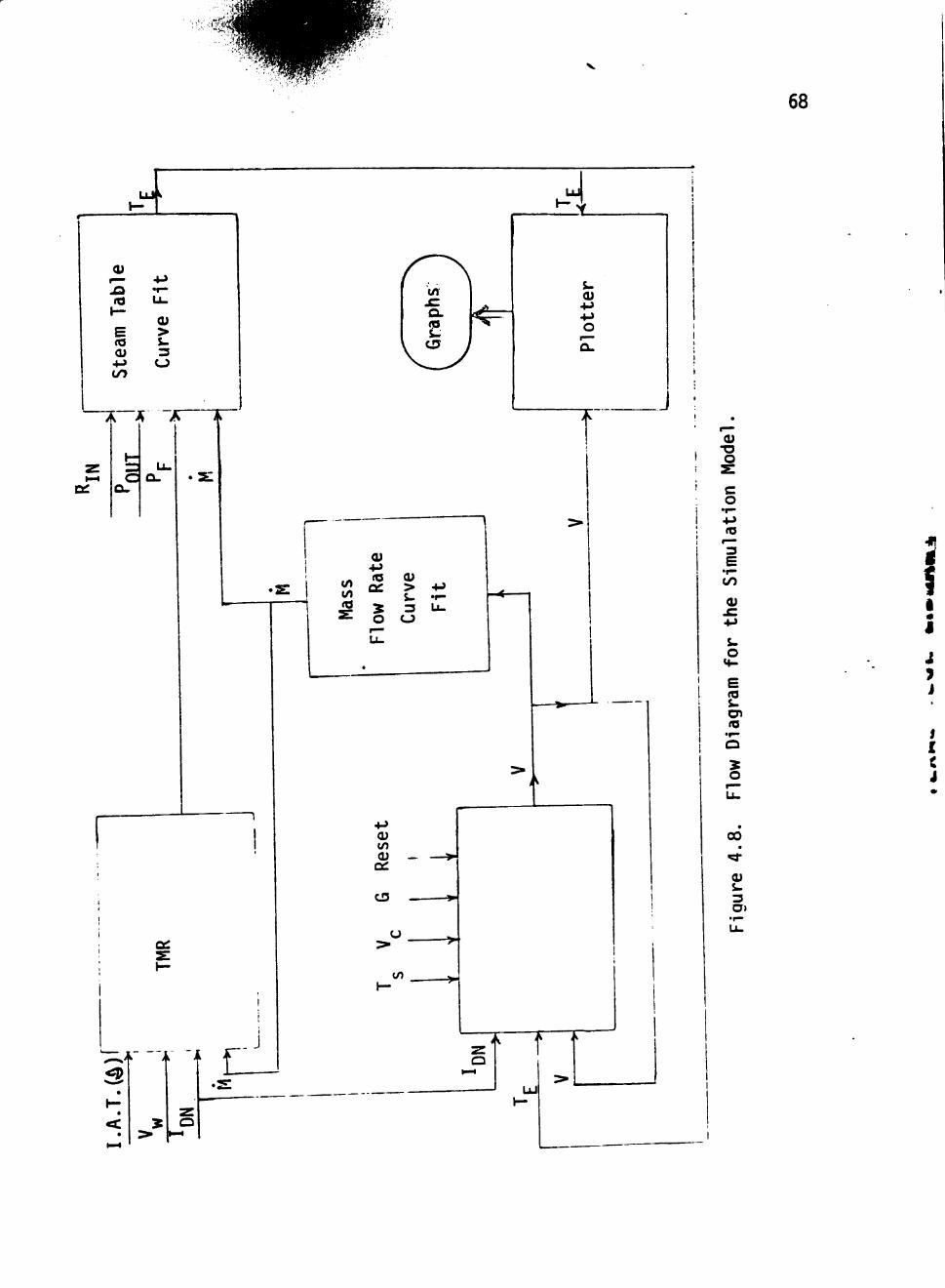
4.5 Simulation Model
The final simulation model is a combination of test computer
Model I with the mathmatical model for Tp. A flow diagram for the
entire simulation is given in Figure 4-8. Appendix D shows the
complete computer code for the simulation. Tests of this simulation
model are described in the next section.
67
CO 1
"id-
0) r^ .£3 m 1—
X UJ
a: o u 1— 1—1
U-
LlJ > r) CJ
UJ -J ca < h-
IS: < UJ
OO
> LL.1
c cn H-OO
O"
<+-
O)
-o
o
-O
.-a
O 2:
cr lU
CM CO cn • ^ •"*
1
t
1 t
1
00 Ln vo •
>—
in o 0 •
0
00 00 vo •
CO LO
1
,_
in in 00 • «;r ^—
i
00 in vo •
•~
CM CM VO • CM 1
CO CO r-
CD
CM
<--
CD 0 VO
1
CM
CO
VO •
r—
1 1^ 1
0 1 ' • 0
LO 1— 1
X
00 1 CM 0
X
r CM 10
LO X
CM
.00
0
CM
0.0
0
LO p>» .
1 ^
1
0 ^ CO •
in 1
cn CO vo •—
in CO vo vo CO
1
CO
u, i CO 1 r^ "•v» CM
,.
CO 0
.00
0 1
r 0
0.0
0
r>. 0 CM • 1
' 0 t—~
T^
r-*. m
CM 1
00 0 vo • 0
«^ 0 CO • LO
^ p*-
1
•K "C-
68
U l l
I— 4-> .O (d
1— E (O <u + j 1/7
• r -U-
OJ > s. 3
CJ
jr~fi T
s .
O
L to IA <0
-M iQ CU
Q : > 4->
5 3 Li-O O
— 1
CU CO CU
a: CD
CO
^ J —
T
CU
o
o
3 E
• I —
OO
Oi
o « • -
E
cn ro
3 o
CO
(U
3
i 4 i i
SECTION V
TESTING AND EVALUATION OF THE SIMULATION
The complete simulation model developed in Section IV (ref. Appen-
dix D) consists of several mathematical models. The overall model uti-
lizes curve fits '.or mass flowrate (function of command voltage) and
exit temperature (function of enthalpy and pressure). It also uses
the TMR curve fit, developed by Dr. Reichert, for prediction of P ,
the power into the fluid. For the control algorithm, an important
factor is the parameter G. A new value of G, known as Gj, developed
in Section IV, compensates for differences in the time steps avail
able in the recorded data from those actually used by the Bristol.
The simulation model has been equipped with the latch-on capability
of the actual controller. Thus, it can accept initial conditions from
the current status of the actual system. The model includes the
clipping feature (0% ^ V ^ 100%) of the acutal controller. Thus, the
command voltages sent by the actual controller and by the simulated
controller are newer more than 100% (equivalent to 10 volts, minimum
flow) or less than 0% (equivalent to 0 volts, valve completely open).
The simulation model has been tested by simulating the controller
and comparing the response of the simulated controller with the actual
controller. The function of the controller is to control the exit
temperature by controlling the command voltage for the feedwater valve.
In order to compare the two controllers, the command voltage and exit
temperature were plotted for the actual and the simulated controller.
The simulation was tested July 5, and July 30, and August 1, 1980.
69
70
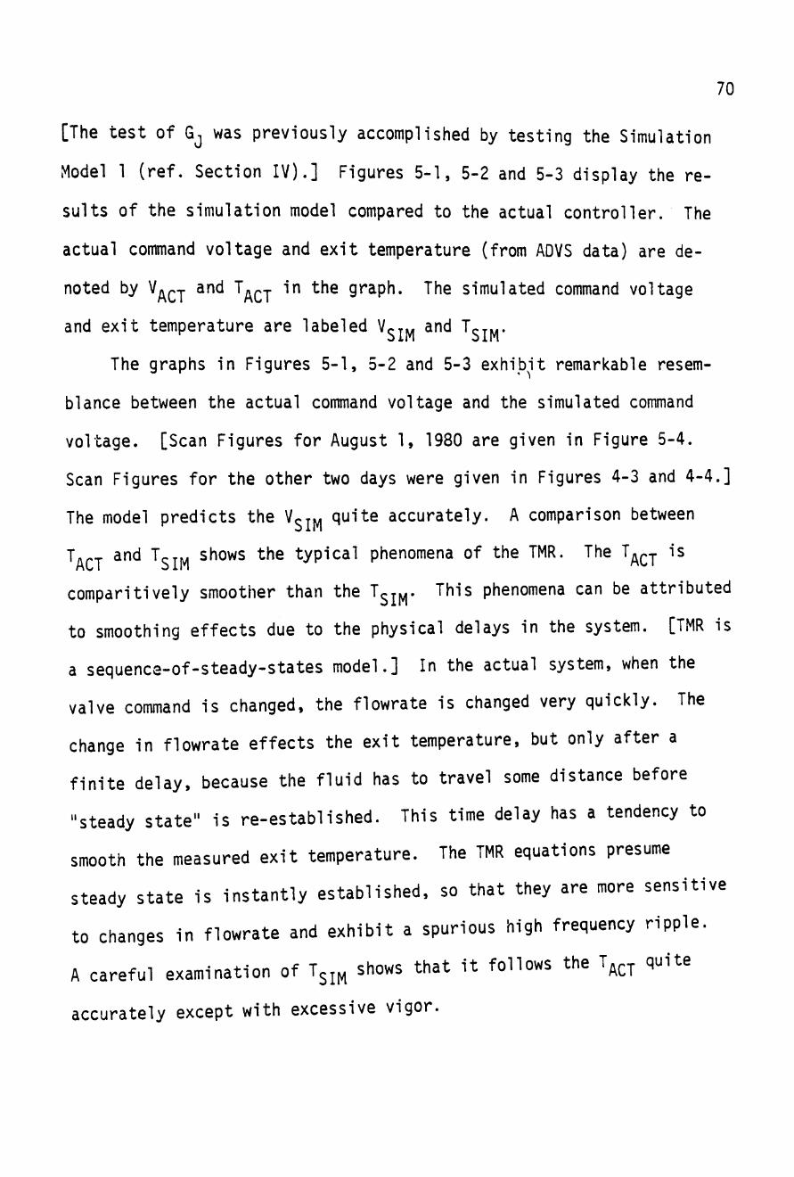
[The test of Gj was previously accomplished by testing the Simulation
Model 1 (ref. Section IV).] Figures 5-1, 5-2 and 5-3 display the re
sults of the simulation model compared to the actual controller. The
actual command voltage and exit temperature (from ADVS data) are de
noted by V^^j and T^^j in the graph. The simulated command voltage
and exit temperature are labeled V^rw and T^j».
The graphs in Figures 5-1, 5-2 and 5-3 exhibit remarkable resem
blance between the actual command voltage and the simulated command
voltage. [Scan Figures for August 1, 1980 are given in Figure 5-4.
Scan Figures for the other two days were given in Figures 4-3 and 4-4.]
The model predicts the V^j^^ quite accurately. A comparison between
Tn^j and T^.^. shows the typical phenomena of the TMR. The T^^j is
comparitively smoother than the T^^^. This phenomena can be attributed
to smoothing effects due to the physical delays in the system. [TMR is
a sequence-of-steady-states model.] In the actual system, when the
valve command is changed, the flowrate is changed very quickly. The
change in flowrate effects the exit temperature, but only after a
finite delay, because the fluid has to travel some distance before
"steady state" is re-established. This time delay has a tendency to
smooth the measured exit temperature. The TMR equations presume
steady state is instantly established, so that they are more sensitive
to changes in flowrate and exhibit a spurious high frequency ripple.
A careful examination of 1^^^ shows that it follows the T^^^ quite
accurately except with excessive vigor.
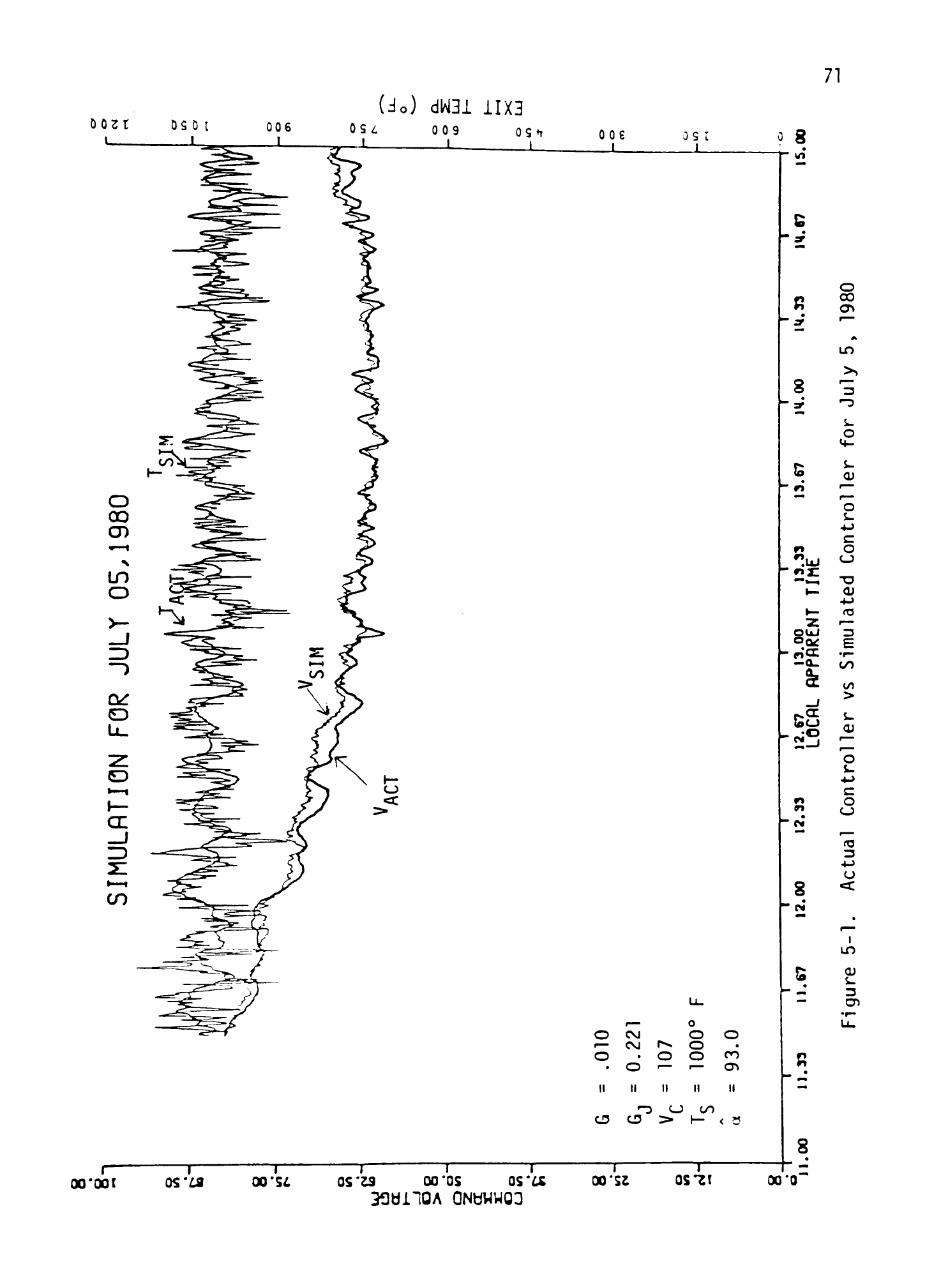
71
00£ L_
as I L_
' 8
fi zr mm
s 9 ^m
1^ n -*
n ".UJ rt3Z
»—
• -Z
OUJ o ^ r i f f —Q_
^
_J
S c j
2-J
r» » i
O 0 0 cn '~~
A
i n
>>
3 - 3
S> O
v»-
CU ^~ — o S-
4->
c o CJ
"O <u 4-> fO — 3 F
• ^ •
OO
CO >
O) '
o &.
4->
c o CJ
c«
o — o
•
II
CD
r ^ CM CM
. O
II
' ^ CD
r o '—
II
CJ >
o O O O • "
II
OO 1—
o •
CO
cn II
< 3
I— 00*001
— I — 05*19
T 00 'S I
— I 1 1 1 r— 05*23 00'OS OS*LS 00'S2 0S*2t
3f3di10A QNUWWOa
8
(O
8
12.
!^ —
(J «=c
f —
i n
3 cn
00*0
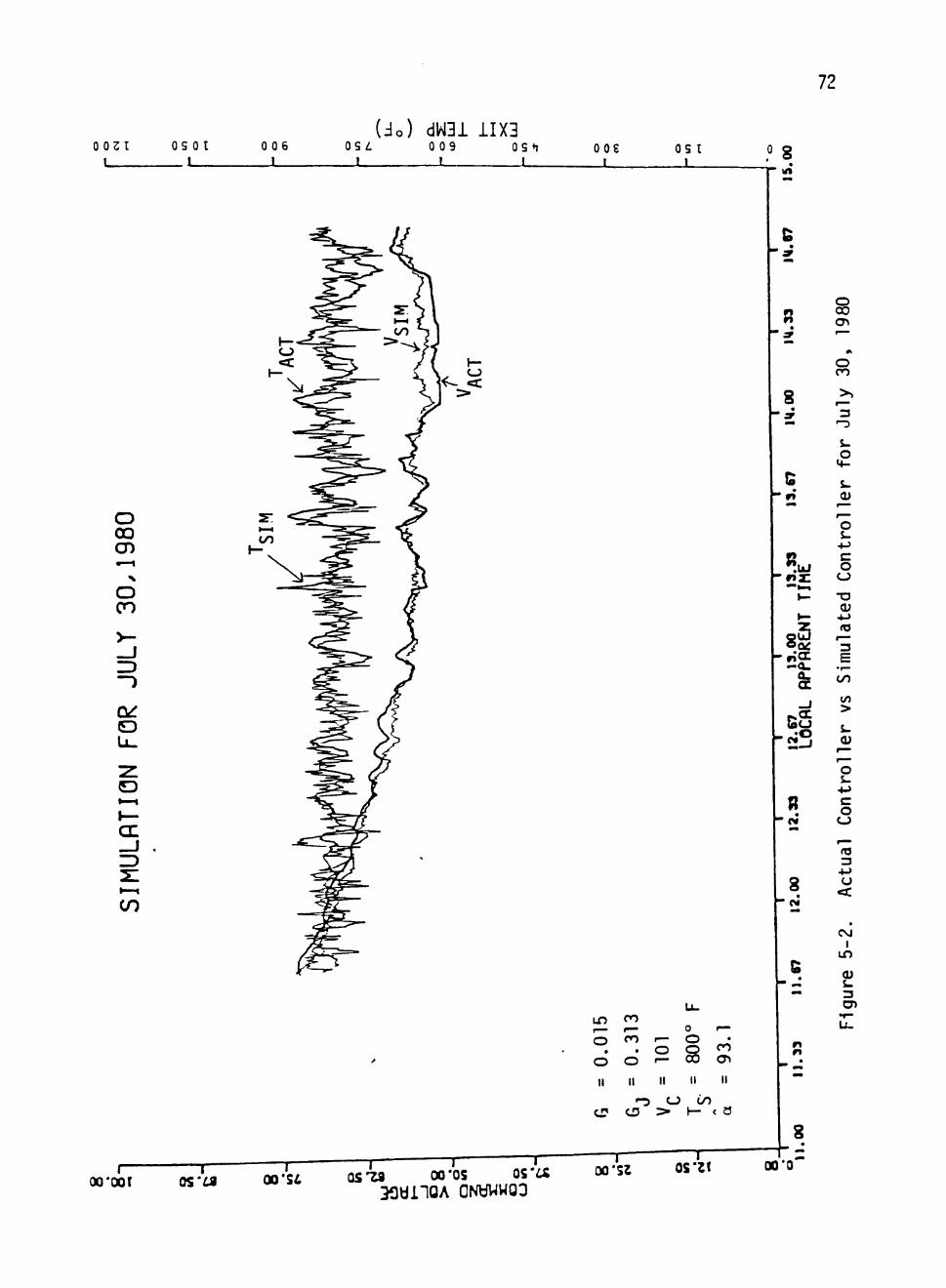
72
0031 I
OS 01 _ 1
006 1
(do) dW31 iIX3 OS^ 009 OS*T OOS —J 1 1 L_
OS t _J
O OO CD •—1 N
o CO
LJL.
I — cr -J
t— oo'oor T"
05'^ T T T T
Ln f M
o • o II
CD
CO * • • "
ro •
o II
'n CD
o 1— O ° s II II
CJ Cn > 1— <
CO
cn
< a
00'SI os-za 00*05 os'u 33«nOA ONtfWWOO
0 0 ' S 2 OS'21
°8 M
.UJ
8CD
0 . GC
8
C
r*
8
00*0
s cn
o CO
8 ^ 3
&. O
4 -
S. (U
' o s-
+-> c o
CJ -o CU
<o
3 E
CO
CO
>
CU
o
o o
rT3 3
O
CM I
i n
CU
s. 3
73
dW31 11X3 0 0 9 OS n
r" O0*00(
— I — os*:fl 00*51
— I 1 ' r -05-29 00'OS OS'a
33«i10A QNbWWOG
0.01
5
II
CD
0.3
13
II
- 2 CD
108
800°
II II
CJ OO > H - <
r—
o cn
U l C4
00*S2 OS'21 l=
00*0
o 00 cn
4-> CO 3
cn
o ^-
s-(U
o •M c o
-a a> + j (C
3 E
00
CO
>
o &-
+J c o
CJ
3
U
CO I
in
(U s-3 C7>
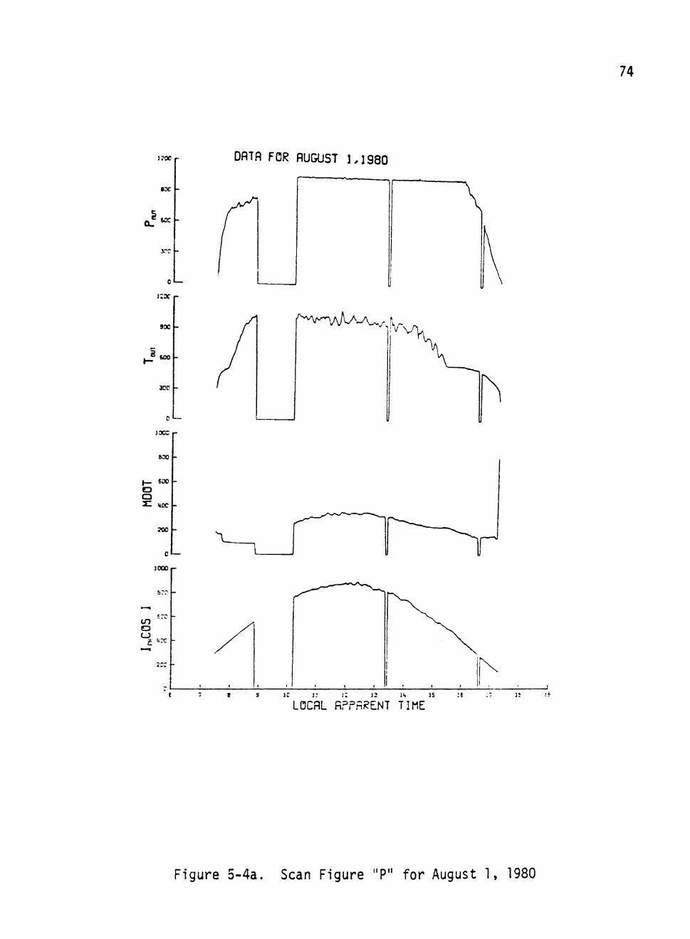
74
170C
»oc
XT -
0"—
9 X
EOO -
300 -
)XZ
800
EOO
o oc
TOO
c«—
JOOC
to o CJ
2or -
DflTfl FOR flUGUST 1,1980
I
f^^V-WU-A^^.f,
X
]S : E
LOCflL fiPPhRENT TIME
Figure 5-4a. Scan Figure "P" for August 1, 1980
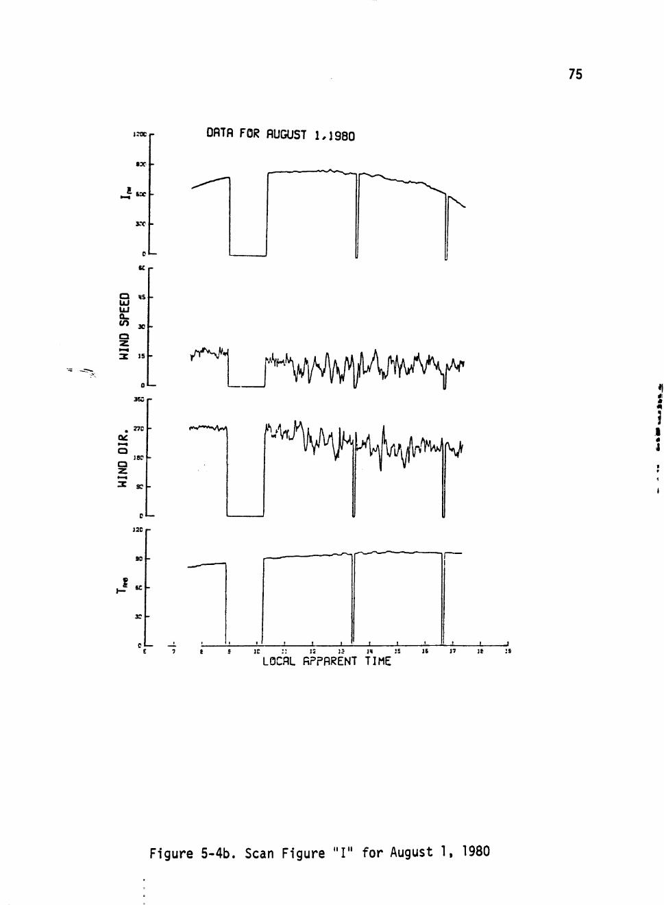
75
i;re
sx
.-? s *
30C -
C I
SC
DflTfl FOR flUGUST 1,1980
a «s UJ a. tn 3C
Q »—i
0
3SS
/('^'^
no oe. a
180 Q Z
C— 12C
90
<««**^~S/\^
I SC
30 -
Cl— - i
' K'
K
^tAi^yi'i'^^W
J !_ _1_ J I
"LOCflL fiPPflRENT TIME IE 17 ]t :s
•
I «
J
Figure 5-4b. Scan Figure "I" for August 1. 1980
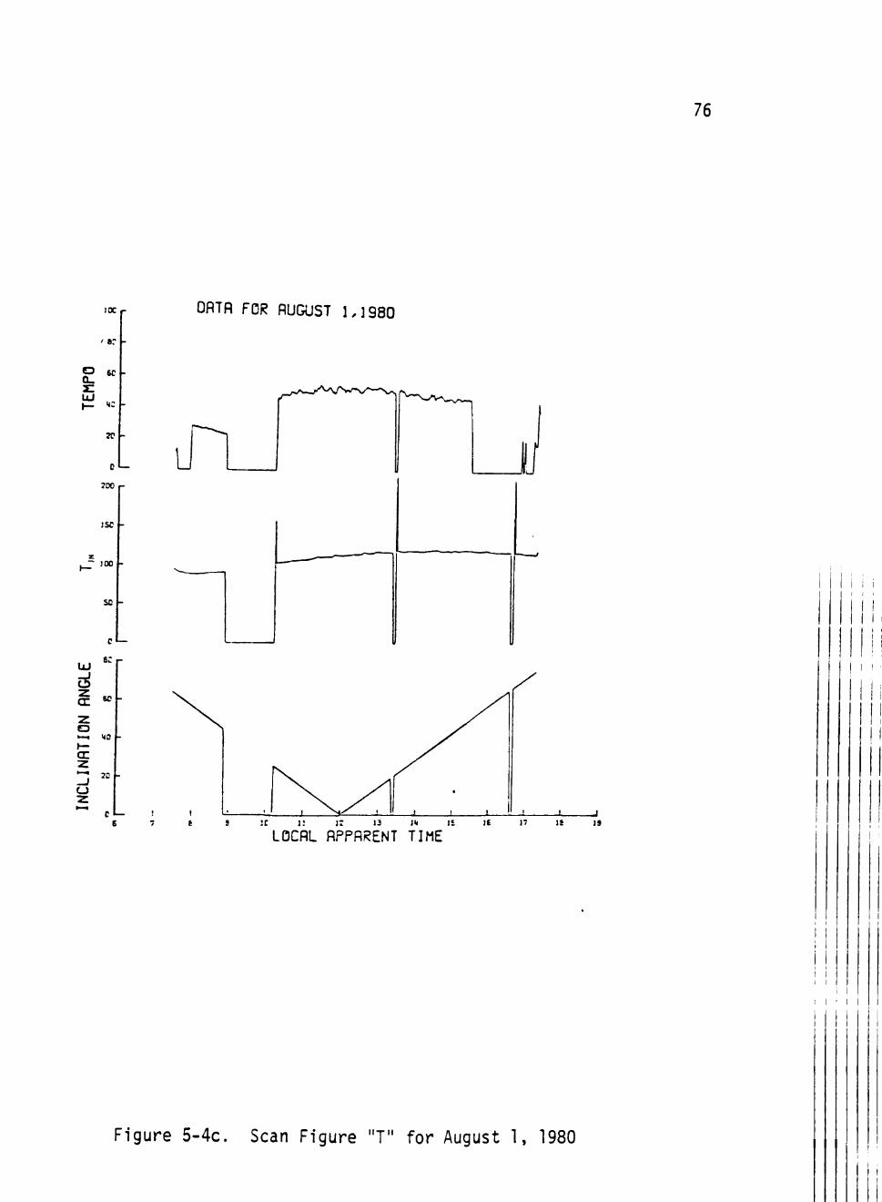
76
IK
' e:
P 6C
UJ .
» -
0«—
700
JSC
JOO
UJ
50 -
e l
se
no
CJ
c»—
OATH FOR fiUGUST 1,1980
u
j
:c i : J : la i>i is
LOCflL flPPRRENT TIME
I I
I ' l l
Figure 5-4c. Scan Figure "T" for August 1, 1980
77
5.1 Simulation Without Using G,
The simulation model discussed was designed to accept data every
20 seconds for its computation of command voltage. This was necessary
because the data was only available at 20 second intervals. The actual
system, on the other hand, was provided data by the sensors every 0.8
seconds. In order to confirm the simulation model, as well as to make
it compatible with the actual system, it was desirable to test the
model when data is provided at the same frequency. Since the data was
available at 20 second intervals, linear interpolation was utilized to
provide "data" every 0.8 seconds. The simulation model thus operated
should give results similar to those attained by the model when using
data every 20 seconds. If successful, the test not only reconfirms
the model, but establishes the direct relationship between the para
meters of the model and those of the actual system. The "sampling
frequency" parameter match-ups would be shown to be unnecessary. The
data for July 5, 1980 was linearly interpolated to create input at
0.8 second intervals. This data was then fed into the simulation model,
and the actual value of G was used, instead of Gj. The results of the
simulated command voltage and exit temperature {^^^^ and T^^^) are
depicted with the actual command voltage and exit temperature (V ,
and T ) in Figure 5-5. The results are almost exactly the same as ML/ I
those shown in Figure 5-1.
This test not only reconfirms the model, but also qualifies the
model to be used for improvement of the controller. Any set of data
can be created and utilized for testing the controller, without having
to make "sampling frequency" alternations in the parameters.
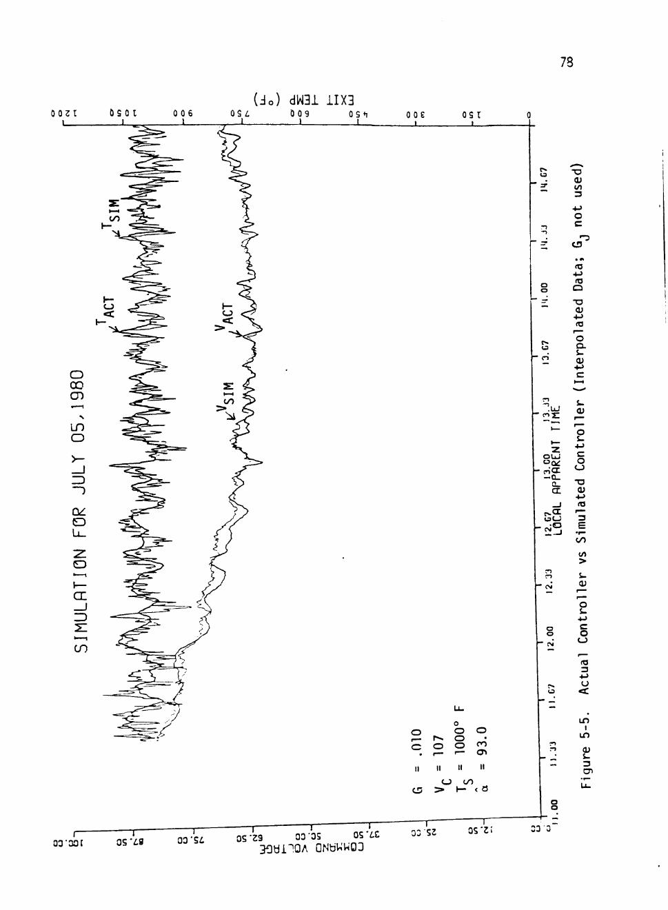
78
(3o) dW3i 11X3 0 0 2 1
I
o CO CD
LO O
Li_
O
CL
CO
0 0 9 I
OS+T _ i
ooe t
OS r
p*.
:T
r) - . —
O o —
C3
r i
"O (U CO 3
+J O c
•-3 CD
• M
<o •t-> ta
Q
"O CU •!-> (C — o £^ i-Q)
'.LU
OUJ C 3 ( ^
oCX - Q _
Q_ cn
GcJ
•o ex i
o o
0 O O O ,— P^ O c o o <
. I— I— 0 ^
II II II II
CJ OO
o c: o o
CU •4->
to
E 0 0
CO
>
o i-+-> c o
rt3 3
• • - >
CJ
in I
in <u i-3 cn
o o
i 03"0OI
T 05*^9
1 — 0 3 ' S i
T T T OS-29 03'OS OS'iC 03 52
— I OS'21 33 3
79
5.2 Testing and Evaluation of the Controller
The control algorithm for the feedwater valve
V = V +K[V(, - <V>]S (5.1)
was derived on the basis of conservation of energy. A gain factor K
(not used in the Bristol) has been introduced in the error term to in
crease or decrease the contribution of the error factor. Similarly,
the variable gain factor, [V^ - <V>], might be replaced by a constant
gain factor, V^. Investigations at the ADVS, replacing [V . - <V>]
with V« = 20 seemed to give about the same results for the actual
system control.
The testing on the actual system gives results which are rather
difficult to interpret, due to uncontrolled conditions in the actual
operation. The simulation model has a distinct advantage in this
regard, because a controlled environment can be provided to the model.
A hypothetical day was created for one such test, and various cases
were explored. It was decided to run a test in which the factor K
was varied from 0.5 to 1.5. [K = 1 corresponds to the algorithm used
at the ADVS.] A test with the [V^ - <V>] term replaced by the constant
V, was also conducted, so that a comparison between the two controller
formats could be made.
Data was created for a three-hour-span for a sun at equinox (for
computation of 4 ; March 20: 6 = 0. AT = 13.04«). The insolation
Ip. was chosen to be
(5.2) I = U , [1 + ct sin 2rTtJ DN DiMO ••
80
where
IQNO "" ^^^ watts/M^ ,
t is in hours, and
a = 0.1
The function thus created is sinusoidal with a period of 1 hour.
The exit pressure (PQUJ' ^ ^ chosen to be a constant; PQ .J. = 1000 psi.
[In the final power plant, the exit pressure will be maintained constant
by a pressure reservior.] The inlet feedwater temperature was taken
to have the constant value T j = 115°F. Wind speed V., was also chosen
to be constant: V^ = 10 MPH. The controller was assigned the set-
point temperature T^ = 1000°F, and averaging parameter was G = 0.01.
For the first case, the test was conducted with K = 0.5, 1.0, and
1.5 with Vp = 107%. The second case was examined with K = 0.5, 1.0,
and 1.5, using V« = 20%. This provided values of 10, 20, and 30% for
KV„. The simulations for these two cases are exhibited in Figures 5-6
and 5-7, respectively. Each of these two figures exhibits seven curves.
The Ip) curve is placed near the bottom of the figures. This curve
provides a phase reference. The command voltage curves are denoted by
V^5 (K = 0.5), V^^ (K = 1.0) and V^^^ (K = 1.5). The temperature
curves corresponding to these command voltages are denoted by Tj^^, 1^^
and Tj^.g, respectively. Study of these curves provides some inter
esting conclusions. In both cases, as the coupling increases; i.e.,
as the gain factor K increases, the controller becomes more effective
in maintaining constant exit temperature. The feature observed at
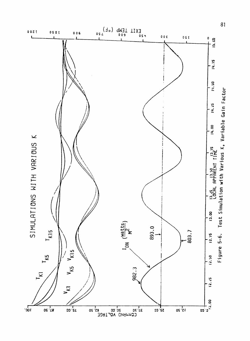
( io ) dW31 iIX3 OSZ. 0 0 9
81
^5
Ui
o . 1
- - •
"*
vo r
— 3' • ^
.00
— 3" "*
i n
• .UJ - c - j j ;
" ~ i - ^
*—
^-2
O U J j ^ a ^
- o ' c r —a.
a_ (X _ j
->JCJ
- c n °
S .
o +J o (O
Lu
c • r "
ro C3
(U r~»
• • S-<T3
> A
:xr
«/) 3 O
• r -
L. <T3
>
x: • M
•^ 2
o •«->
— <0
o a o —
tf>
^ r ""
o j %
OO
+J CO 0)
1—
• CO
1 i n
CU &_ 3 O )
•r—
o o
OS'^0 03 Si OS'23 03'35 OS*£.C 30bi"'0A QNtiUWOJ
33 52 QS^zr 03 3
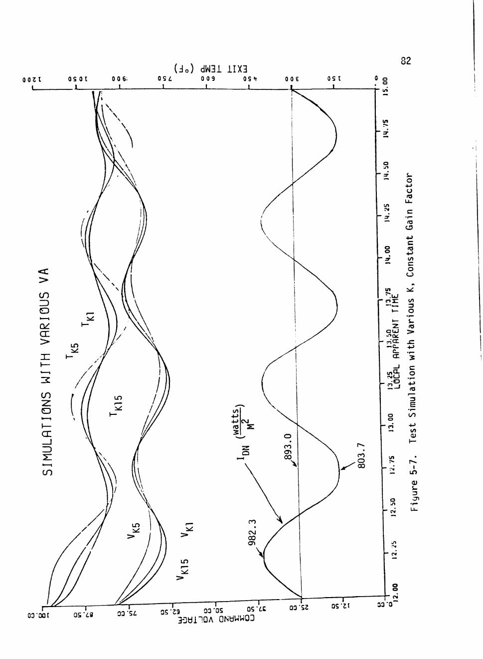
82
o W1
— sr • ^
i n r i j
— 3-• " •
O o
- ^ ""
i n
• . U J - 0 3 I
" • • — .
»— • ^ 2
O U J - i Q t
- r^CX — C_
c_ (X
_ J
tfl?^ 1 ?>j(j
o o
— r! .-.
i n r»
— r>4
o \n
S. o
4->
u «o u. c
• f—
rtJ CD
4.^
c ( 0 + J CO
c o
C J
A
:^ CO 3 O •^ s. <o > J C 4-> • r" 5 c o
ati
— 3 E •^ 0 0
+ J
w» (U 1—
• r^
1 i n
(U &. 3 CP
•r—
J1
o o
O3'00t OS'68 03 'S i 05-29 03'OS OS'it 3-3«l"lDA aNtiWW03
03 52 0S'2I
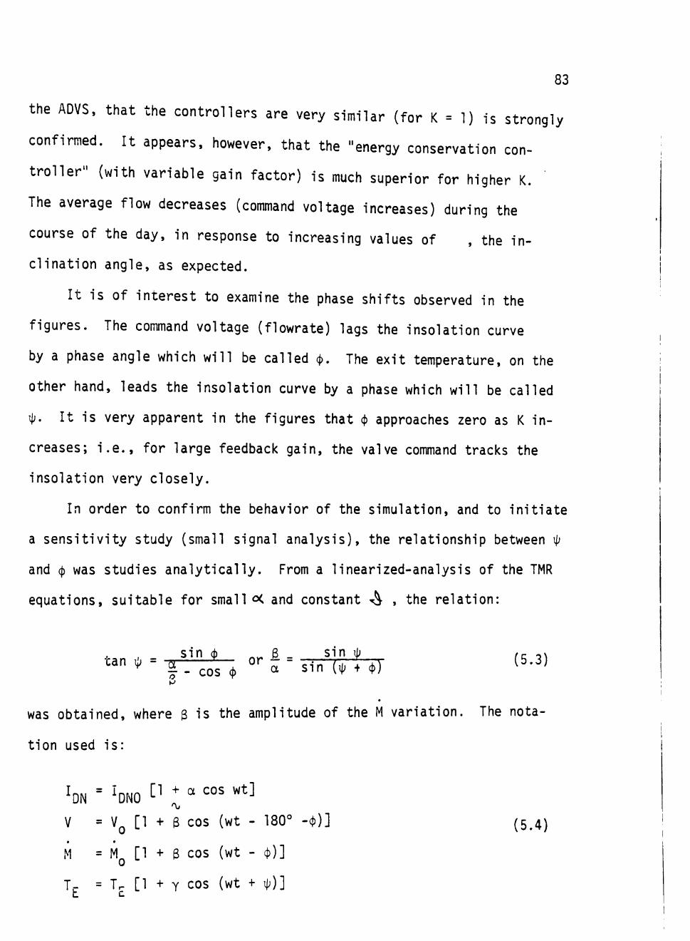
83
the ADVS, that the controllers are very similar (for K = 1) is strongly
confirmed. It appears, however, that the "energy conservation con
troller" (with variable gain factor) is much superior for higher K.
The average flow decreases (command voltage increases) during the
course of the day, in response to increasing values of , the in
clination angle, as expected.
It is of interest to examine the phase shifts observed in the
figures. The command voltage (flowrate) lags the insolation curve
by a phase angle which will be called (j). The exit temperature, on the
other hand, leads the insolation curve by a phase which will be called
i). It is wery apparent in the figures that <^ approaches zero as K in
creases; i.e., for large feedback gain, the valve command tracks the
insolation yery closely.
In order to confirm the behavior of the simulation, and to initiate
a sensitivity study (small signal analysis), the relationship between i)
and 0 was studies analytically. From a linearized-analysis of the TMR
equations, suitable for small <X and constant T^ , the relation:
sind) 8 siniJj /c^x
was obtained, where 3 is the amplitude of the M variation. The nota
tion used is:
V = VQ [1 + 3 cos (wt - 180° -4))] (5,4)
M = MQ [1 + 3 cos (wt - cJ))]
J. = T. [1 + Y COS (wt + ij;)]
84
It is clear that the relationship between i|; and 4) is very sensi
tive to the ratio a/3. [If a/3 = 1 then ij; -v 90° as (J) - 0. If a/3 M .
then i|; ^ 0 as 9 ^ 0.] Thus, for small (^ (large values of K), the value
of 3 must be determined accurately in order to calculate -^ accurately,
and conversely. Values of ^ measured in'the figures are compared with
calculated values (using values of <j) and 3 from the figures and the M
vs V curve fit) in Table 5-1. The results are close enough to give as
surance that the code is behaving properly.
5.3 Future Use of the Simulation
The main purpose of this study was to develop a simulation model
for study of the ADVS process control. The simulation model has been
constructed so that direct compatibility exists between the model and
the actual controller. This provides a unique opportunity for studying
the controller under any circumstances and conditions. Hypothetical
data sets can be constructed and applied to the model for evaluation
and testing of various control algorithm. The preliminary applications
described in the present section have already produced interesting con
clusions. It is expected that further application of this simulation
will assist greatly in the development of the control algorithms to
be used in the actual power plant to be built by the Crosbyton Solar
Power Project.
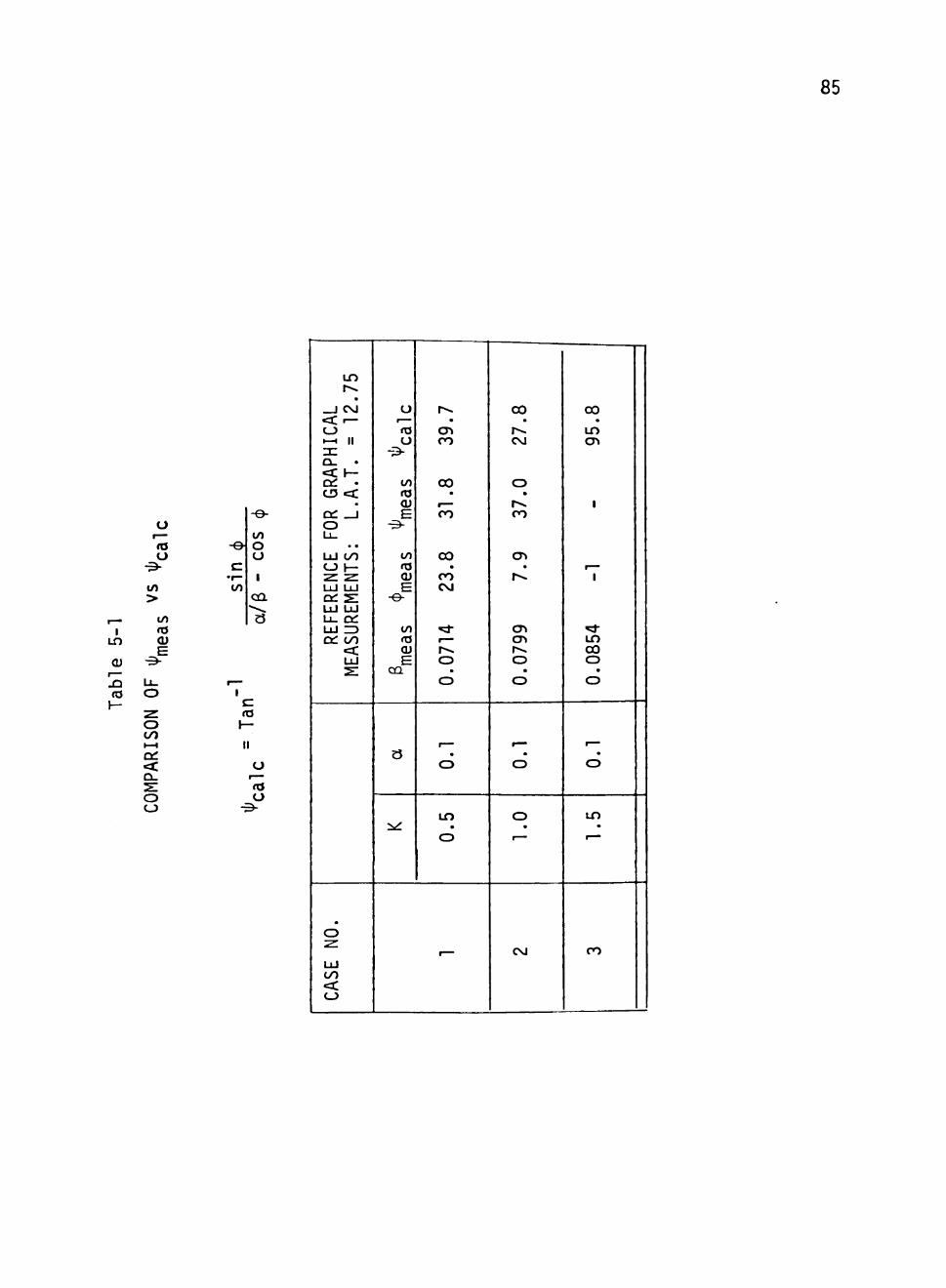
85
u
^_ 1
LO
CU
JD ta
\—
r— la o
-3-
co >
to 03 CU
E • ^ •
U -
o ~^ o CO » — 1
Of < CL.
S O CJ
-e c
•r— to
to o CJ
1
ca 3
,— 1
C (Q
1— II
O r— ro U
- z5-
REFE
RENC
E FOR GRA
PHIC
AL
MEAS
UREM
ENTS
: L.
A.T. = 12.75
CASE NO.
u
<o o
- >
to <o CU
E
to (0 CU E -e-
to <o CU
E CQ
3
•^
0.0714
23.8
31.8
39.7
0.1
0.5
-
0.0799
7.9
37.0
27.8
0.1
1.0
C\J
0.0854
-1
-
95.8
0.1
1.5
ro
REFERENCES
(Bristol Instruments/Systems) Bristol Instruments/Systems Manual, Bristol Division of Acco, American Chain and Cable Company, Inc., Waterbury Connecticut.
(CSPP III) "Crosbyton Solar Power Project Phase I, Interim Technical Report", Volume III: Appendices I-M, Texas Tech University, Lubbock, Texas, February 1977, ERDA Contract No. E(29-2)-3737.
(CSPP VII) "Crosbyton Solar Power Project", Volume VII: Performance and Cost of Solar Gridiron, Texas Tech University, Lubbock, Texas, February, 1981, USDOE Contract No. DE-AC04-76ET20255.
(BB) Brock, Billy C , "Optical Analysis of Spherical Segment Solar Collector", Ph.D. dissertation, Texas Tech University, Lubbock, Texas, May 1977.
(SC) Chao, Shih-Cheng, "Computer Based Data Processing System for the Crosbyton Solar Power Project", M.S. Thesis, Texas Tech University, Lubbock, Texas, December 1981.
(HL) Leung, HipSum, "Optical Power Concentration on Aligned and Misaligned Receivers in Solar Gridiron Power Systems, M.S. Thesis Texas Tech University, Lubbock, Texas, August 1978.
(KW) Watson, Karan Lea, "Performance Analysis of a Solar Gridiron Design Verification System", M.S. Thesis, Texas Tech University, Lubbock, Texas, May 1981.
(SAS Language) Barr, Anthony J., Goodnight, James, H., Sail, John P., and Helwig, Jame T., "A User's Guide to SAS 76", SAS Institute, Inc., Raleigh, i orth Carolina.
86
APPENDIX A
PROGRAM AND OUTPUT OF THE M CURVE FIT
87
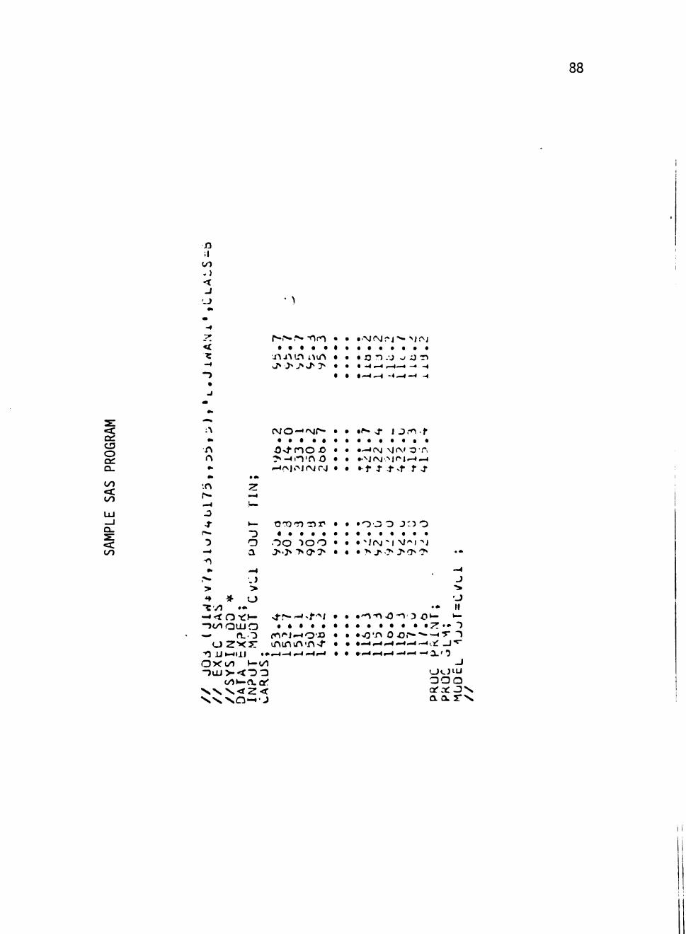
88
:l OO
J
< •z
J
•i^ JA ir^ nvA • • • o n - j v O T )
to o on Qu
CO
to UJ _J a. < CO
n ( •> ••
'.n r^ .-4
-3 4-
"3 •^ -0 •>
,•>-> • -«vl
• «k
"Z >^ u-
a
—4 . ) •>
* o • »
- •< t o^c:^--JOOQUJCD — rt. O
O ^ '^ _
O X o n ^-00 - o u j > < " D 3
co^-n-cr: V N . \ < Z < ' v ^ K ' s n - ^ ' j
fvjo-*'Nr*-
^ > t n o - o ? » - « o ' n o ^o>l«'^JiNrj
C^OT) cor*
O O " > o o > . > > a » >
> i - r - ^ - t - N • • • • •
•
• • •
•
• •
• • •
•
•
• • •
•
• •
• • •
•
•^->r J j m . f
•—«fM vjrvi :3'r> ••^j r\x>\^\'-*^^ • - i - 1 -f ^f f r
• 0 ' 3 0 J:5 0
• " i fM"! N/' l J • ?* J* 'C'* J* (T "^
. • • ' " 0 - n o ^ 3 o^-• • • • • • • ^
. *
—4
J "> •J II ^-
. - T • >0 "n 0 o r - •«-.>-« -r ^
r^4i - . i r - i —<-^ —«a.
o<
•5 J
L J I U Q O Q a'.t: J N . a a r > s
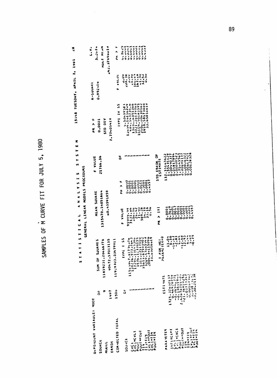
89
fl s
•a
• f > » • J
yj -4
< —
C C
— »
r •
• . • • • • • • • J 3 3-3 3 3 0 3 3
CL
O
UJ 3
00
< f
I •
oe o
oe
^ >
o a o • a
o *-
U > a N 3 C 0 3 N 3
< 3> -S -N 3 —-*'>4 3 > "3 >4 0.0 »*>
</\ <o 3 JO 0 » » o —
Ol C 0 ^ C 0 * 3 O f i - i ^
^ l . a t . l . . .
o 00 cn
t n
a: o
UJ
CJ
U-
o CO
-a: 00
z Ui
^ 1/1
>-t / )
O l
ee 3
l/l o 111
M 0 a
1/ er a.
> * / i _ j _ i
UJ < 0
0 z r
< u; Z
<
ee M tU
Z K lU
a «/t
. 4
K
«
U i 3
< > u.
U i ft
3 3
2 < UI X
i / i UI of < 3 1 V I
•0
t
•a
•a h .
^ fM
•t •0
0
• 4
• 0
0^
• 4
'O
« 0 > * •
«
f ^
» l/^
• 4
IT • *
. 0 0
« m* t n i —
0 »>.
•irf
. 4
0-P"
* "
u. o
-.-.-.-.-.-•-•-«-• i . >r».^•n^/^".<M—«
t.X - 4 * / < « 0 3 « 0 « J
j ; . t • • Ovu M . 4 O 0 O — O 3 O 0
3 0 0 0 a o a O " ' * 3 0 0 0 —"JOO «< 3 0 0 0 30flO *
0 0 0 0 3 O 0 O 3
Ui 7 ' « O N 3 » 3 £ 0 o > i o - r 0 0 0 0 3 ^
-» • • • : ' / I : J ^ ^ o J - 0 0 0 0 0 3 3 *
0 0 0 0 0 0 0 0 3 0 ft
o » n
^->_.ny>rf« 0 - - 3
. • . . . . • • • O — (M
r - 3 »•
«
o - I
i i> - *
af>u
O T
•<.
n.
'i- ^ '^ Z X a ^ Si
o o T
' 03 >'--"'-'!::;:1 — • • • I f t — - " ^ 0 ^ • . Off . r > « ' - 0 ' ' * - o J
- , * 3 — ' - " - 0 3 ^ T . . . . 0 • • • • •
^ I I * 7 '
^ <
UI .J
4
< >
Z u 3 O -* i
•i. S 3 5 S o «/» t UI
O J 3 3 r z
• > o r o — o - V i = • • • Ui *-> ^Zs>-^ » — - " -
i >>3 3 >>0
s r 3 3 ,^^£ r * ^ • T i l l :J ;^j! io3rzXl3 2 r>>32—**?

90
I
U O
3 :; r t
•r
< O lit
u o
< *
3 O r» ^ i/t e> I •
of O
^ 3 3 3 0 3 3 ^ 3 J 3 0 3 3
3 J 3 0 J 3
a. 3 3 3 0 3 0
-U O"* S - 4 * / > 3 < f - 4 > h . O r t -J • • . I f •
-i 0 - 4 . 4
«%
• O. •< > CO
O Ui u^ A O a rn
O ^-ae • O <M * . O t - «f
1^ rg
-^•O 3 * S ' " ^ N— r-"ot>
Ui 0-* B'»9-<'\ a. n O'ft^ to V • * . . t •
— oo.raj«-o
o 00
IT)
o
OC
CJ
OO
T
U i
» •
M
> •
</t
t i l
. 4
Wt
V
^ <
z
<
J
<
u
"* ^ v»
N «
^ < K
l A
U i
oe 3 o Ui
8 oe a.
Wl
^ U i Q O Z
ae < U I Z
- i
- i
< u
z UI Id
U I 3 .J
< > a.
UI ec < 3 T Wl
Z
< UJ
Z
l/t U i ac
< 3 T i/»
' \L
o
Z 3 vf
. 4
• N f>. «0 m r
^ f « «T O « 4
« ^ f»
• lA lA (M
»
-r» (Vi IM
« O . 4
* • * i n
^ lA . 4
e
<A
.» * ^ ^ IM
« . 4
• « r»
•r m •o
». ^ t
^ r • > •0
. 4
* « 4 . 4
a
. 4
. > ^ r» • * •
1 ^
OB
. m O r» »• IM
»•
O - 4 3 ' 0 0 - * ' n » Ui •»•II»M»•^- o ^ •
a e ^ * M-'iO'Mi/'P". 0 « (^^«M4<» 3 .4 OCX ''^•ooo-t-r-t of— Q i W O i M O - O O < i iv ^ r M O O O - n o
aui ^ x O O O O O
O-* —-4 — 0 0 0 3 3 0 0 0 0 0 3 0 O O O O O O
...... J 0 3 0 0 3
M > > M i / \ S > l A — . 4 ^ ^ _ ^ ^ ^ 3 ?•^-.O^^A •- O O O O O O O J . . . . . . _ O O O O O O O < » ' 0 r - » » ^ O O O O O O O > J> S 0 O •V.N A . » « . . . •
( ^ • ^ x ) ( ^ - 4 O O O O O O O u. ^ — ae
^ a.
Ul « 0 * « " i > r > ^ O i»>OV> — 0 > 3 0 Irt • • I M O ' S ^ . f • . H '0'Ma>'M*>l/\>4
s - - - « > a " < Oaf • • . . . • . .4 r-..-Ofn» xui •TOie\r'-^0''
«^/^ lMl /^»> — 1 .4 | ^ i - . ^ Ui ^ , f r . 4 ^ p . a e i i I I a —^y>- a'*> o x
n - 4 f ^ o o . . . . . . ^ * 0 " > 4 » 0 ^ O f f ) * ^ < 0
if« .4
U. <
a.
U. « O 'O
° 5? S o Q r
l i . * » ^ a 3 f . * ^ o *o
>» O « » O . 0 ' » l M
T • » « • / > • O O f M
*» . - ^ * * o * ^ ^ O i/» (^•oo^ln^r>^ Ui •oao." — B S . . . . . . .
^^000-^3 «r.4 I I I
<
oe
>
Z Ui UI ^ 3 u U 7 U ^ « Ui Ui or Ui 3 ^ a 3 O tf ae Ui o 3 or O Q </l X Ui U
3
o a •
<j z
> — Ui
nr - • — — •4 — 3 O V J 3 0 Z O
O - f c > 0 > — > I/l (.ioao^o
Ui a 3 o z - .u o > — Ui o a u ^ r ae • • •
X » - t - > 0 3 0 Z v J « Z > > 3 > — >
^ .40oao^o
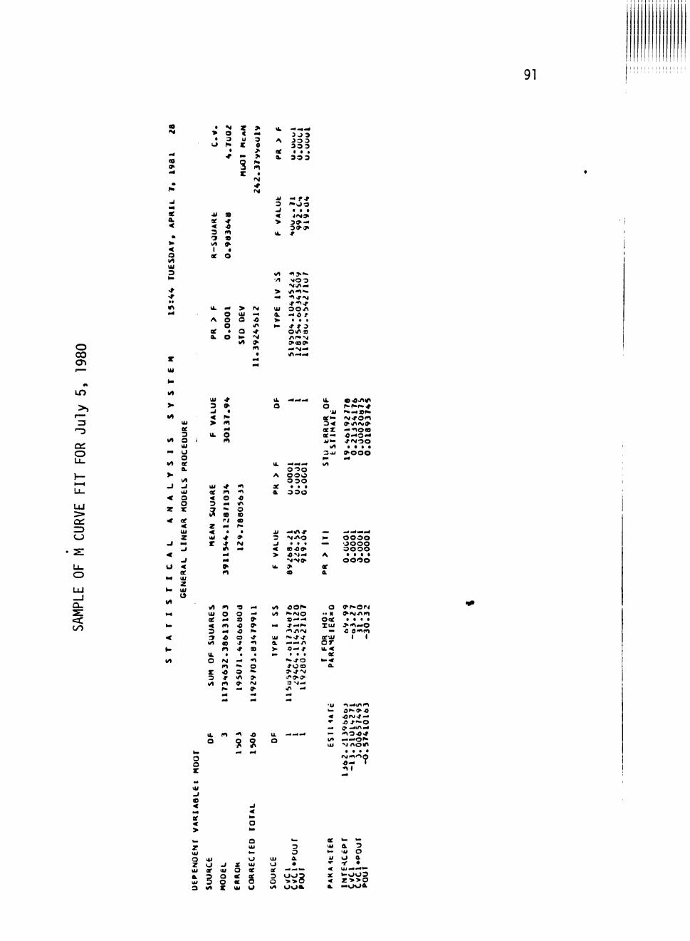
91
CO
oe a, <
< o UJ 3
• > • \J
Ui
ae < 3 3 l/»
1 ae
•M O 3 r» • •*
9
i m 9
• O
z < u z
s z
> . 4
3 0
> > m
t IS •t
I k
A
ae a
j i
3 < > UL
• 4 ' ^ ^ 3 J 3 3 3 3 3 3 3 I • .
3 3 3
- f-r / • ao
i>Ma> 3 ^ - < 3 » 0 » •f
o CO cn
U. .4 > IM O Ui M
A O 3 -0 O li^
oe • Q ^ a. o >> N
lA IT
Z Ui
1/1 • n > ' « . •/I M O 3
N i / I —
Ui o o / > a -40 r >> • . • »- * t 3
O i i ^ «
— •M-4 <A.4.4
CO
a: o
UJ :> ZD
lit
> IA
Ui ee 3
lit O i UI
•4 I J o
IA ae a V
lA - I .J
Ui < o
o Z X < oe
<
u < oe
M Ui z
k. Ui
1/1
Ui ^
3 »
> m
o
Ui ^ in ae n *^ < o -o 3 "« ir 3 - O ^ s o
ft CO Z . 4 P-
< • • UI <# »
' j; 2
o o o A o o o
0 3 0 ae t . •
a o o o
3 '^iJ^O _i . . . < g e o ^ > ON.4
u. >
O ^-^•f»# 'ii • • ^ s ^
ae*» n-tOf^ 0< O-liMM* aex —-no«8 ae— • 0 . 4 O 4 4 Al>- ^ « M O O
UI • I • • Ooi > 0 0 0 ^ •4 I/l
N. o o o o — o o o o
o o o o A • t • • o o o o ae a
1/1 m « .4 Ui o o -4 ae .4 a ^ < 1^ •c T 3 — O » 3 * O * I/l B -f 1
r» * B Ik • • • O IM .d 41
m •" o X < o *• 3 * rfl » I/l m ^ IM
» — »•
I / l flOfx M M O
» —— . 4 ^ . 4 i »
UI P * ^ ^
a —.*./> > 0 " 4 t ^ . . .
« . ^ o * O C J lA .4
o
Ooe l U i
aeui o r u.«
* ^ • O r i
. • • • > 4 1 » 4 0 O Oi*»m
I I
h>
o o X
„ Ui - i o < . 4
ee < > w z U i 3 Z Ui
a Ui 3
U.
o
UI
o O '
B wt
n
^ U i O
o X
4 1
? # 4
Z
a OC U i
•o % m4
- i
< h .
o b .
O U i to.
o UI
ae ae O u
u. O
U i
o or 3 o I / l
. ^ - r f » 4
k a
3 O a • ^ • ^ ^
•i g O O *
' I i .1^1/141 b. d ^ > > 0 « •OfM-f-4 •• o r — o * . ^ .^1^*4 — • ' l O * ^ I/l . i a > . 0 ^ Ul -J n o 1*1
. . . . i M m o p <— T •O l
ae k- «-Ul a 3 w lu o u o a T -,- • < U J — " ae h>oo3 4 Z > > 0
a —ooa
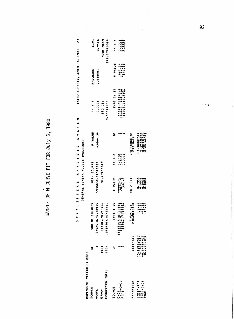
92
IM • -o
> . 4 • ^ U i
U ^ X
z ^ — o o o O A ooo •o O o o ^ oe . . .
t 0" OL O O O O r» O n i X .
IM
Ui ^ r ^ ^ . 3 l A c O ' T .J • • . < ^-^^ > « « «
e - o - . U. IM
o </« Ui
3
U i - • ee o < in
O to I / l ^ I I
oe o
I / l e o « 1/1 •0(MC^
> 9 - - i < o — « V i « r
^ • a ' - . Ik — > e Ui ^ c m
o Ui a a . O i ~ — A o o in > • . .
o • * • - — * ce » o ^ -4<ro> a O ^ 1*1 r sofM
l i l S « > 4
O CO cn
in
o
UJ
ct: I D CJ
Lu
o LU
a. <c 00
I / l
ee 3
I/l o U l
— o o
• 8E >• ^ -J
Ul • O
o
ae
Ui
o < ee
_ U l
r
Ui -f 3 « ^ • > «
O
u. o
Ui « ^
oe »^ «M < « o 3 <^ ^ r» h» o I/l o -r
Z >0 "M
Ui
X
l»»
«A li> -O -< Ui — O* - • CC 9 ^ O-« O <9 <>
S IM m f -
IM IM < I/t 1^ 94 m
9 0> O I L . . . O e <r m
- . ao o X i n — ^ 3 iM ^ 0> V * ^ ^ ' M
h - — *
I k C — * 0 < J O
A C O O O O O
ae . . . a o o o
Ui OIM^-3 e-*"^ _ i . « . < ^ i » i » > ^»*«s
» o — I k 0>/M
I / l * » ! <
— ^ ' - « 5 | . N < ^ ^
a . - * - » n > e o ^ . 4 ^ . . .
C M I M
e r e - 4 l f>-4
I t r\i.C'^-' O . « « ) M r >
Ui i / v m ^ i 4 |
aeto r^^—« S Z O ' ^ m - 4
a e — W C ' O O U i ^ m * o o
t/l . . . . Oui ^ • o o O ^ . 4 I / l
• ^ i n • . . 4 ^ k- m o o o — » o c o
^ o o o A • • • .
o o o o ee a
• * • ( M « 4 A 4 ^ * O C . . . . xu i o — i n «
k . I f . 1 ^ — aeui I I
ox u.<
ee
1*1 -O I k
o o o
O o Z
Ui ^ i n ^ ^
< m.*;ro Z Oo^o — . — r g O J ^ •— < 0 ^ 0 > f M I / l O ^ - ^ f M Ui i n ^ i . « o . . . .
• T t f l O O I - • I I
> O
z U l
o z
o > O o
^ OC Ui O • _ _ u/ C ae oe ——'^ a. 3 o oe « 3 0 0 3 Ui u o a, o O > > 0 O I/l X Ui o x^ o o a
a o Ui > o o ec • U l > ' - * ^ • - 0 0 3 z > > o — o o a .
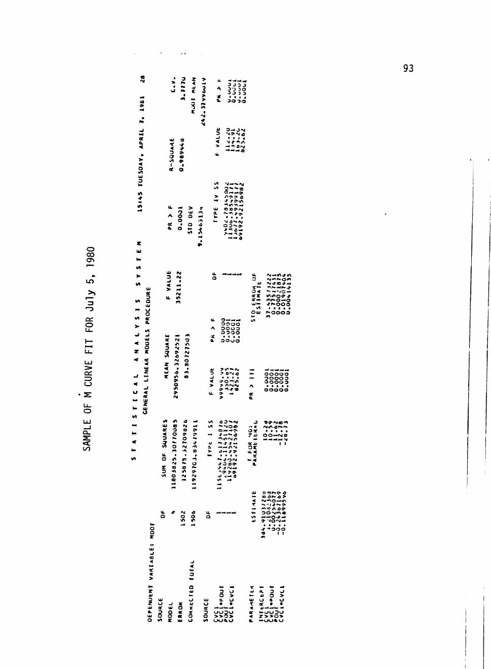
93 'M
(9
ee
< o <A Ui 3
• ^ vJ
U i t < 3 car i/» 1
ae
3 ^ ta n
9
9
> « <
o
z < • I i
i Z
> • 4
2 > > <n
• • r
O i
A
I i 3
< > I k
• . - 4 — ^ 3 J 3 J 3 -3 3 0 3 3 3 3
• • • • 3 0 3 0
O — J N N » N . O
• f i t
— * l 0 < M
' ——a
3 Ui (.1 A G O —
O i<l ae • o o
a o >. ^
vl ?l
1/1 N — •« fM «/> 3 ' » ^ B
0 » i 4 » . 9 k
> -n^o- c — -t -f otn
•om-n — Ul a > a > > M a "-•^ fiy. V • . • . k- NO"»M
O O - f f .
— O
O 00 cyt
LO
a: o
wi
Ct:
CJ
o UJ _ J O-
<c O l
>
M
M
«4
I / l
V
^
<
z
<
^
<
o h4
»-M
* 4
H
< • i .
I / l
U i ee 3 Q U i O
o
& I / l
U l O O X
ae < U i
z
w < ee ! i i
z U i
o
w o o
Ui 3
>
t L
U i oe < 3
Sf z < u i
X
I/l U i
ae •« 3
5f u. o
X 3 ! / l
U i
o
IM
a . 4 • 4 fM m f/|
M
IM i n
9^ •0 IM (*l
t
•0 i n
^ o i n
^ N
i n OD 3 O r » iw
O
n . m
IM S3 41 o a . 4 . 4
*
m 3 i n
IM
O
• <n a
•o IM
a » o ^• IM
'«! . 9>
1 ^
S i n <M . 4
IM O
m - 4
>4
. 4 ff>
^ ^ •* f n 9
• -1
o ^• ^ IM
. 4
•e o m . 4
Ui
a
I k
A
oe a
M 3
^ < > I k
v/1 I / l
.^ •u a.
> ^
I k
o
- 4 . M _ . 4
3 ——— 0 3 0 0 o o o o 0 3 0 0 • • • •
3 0 0 0
y i i ^ " " I M r C M / }
. . . . ( 7 ' O ' O ' n 7 n r M i M ^ • n * «
o —
>
0 3 * » » M • » ^ o « Q . 4 ^ ^ J ^ - ~ - « ' * > i n ' M n " - . t * —
— — n ^ • O — J ' * . . . I
" - > f O i M - / O S » ^^ . f f M — " ' O T ' ^
i n . 4
w4
1 . mm^w^
u. 3
oex oe— 'XI —
I/l oui
I / l
^ . • «. A
or a
J " n oae TM
^ a e u i
o x U i <
« — *
a
Ui
<
^ I / l U l
i M — i n . r i n ( M < « f » 0 ' ' >
" • — - i O -i n i n o 9 . f o i ^ O — O " f ^ - O O O
. • a . t r * 0 0 0 3
(
. 4 i _ ^ M M
o o o o o 3 0 0 0 3 0 0 0 0 3
* . • • . O O O O O
• O f f ' I M B ' ^ i M i n ^ r ^ i ' ^ .
• . • . . O O — I M S ^ ^ ^ ^ 4 'M
1 1
o n j r - o - O ^ D • 0 ^ - • « > r 4 " i o - 4 i n
4» •? n o ^ 3 0 M i » i a
— o » f — » - i O ' M . 4
. . . . . ^ 1 3 0 0 -» 1 1
. 4
ae
>
<
M
z kl
3 Z Ui
a U i
O
Ui
o ee 3 o I / l
-1 Ui
o o X
X
o X OC U i
o U i
— o i i
X X
o o
U i
o oe 3 o I / l
h» ^
3 O o > a o • • . • t ^ ^
0 0 3 0
o o a o
X . . i
^ Ui
T < ee < a
^ ^ 114
n. 3 O i i O > o a o ee • • i i - 4 . . ^ — — 0 0 3 0 r > > o > — o o a o
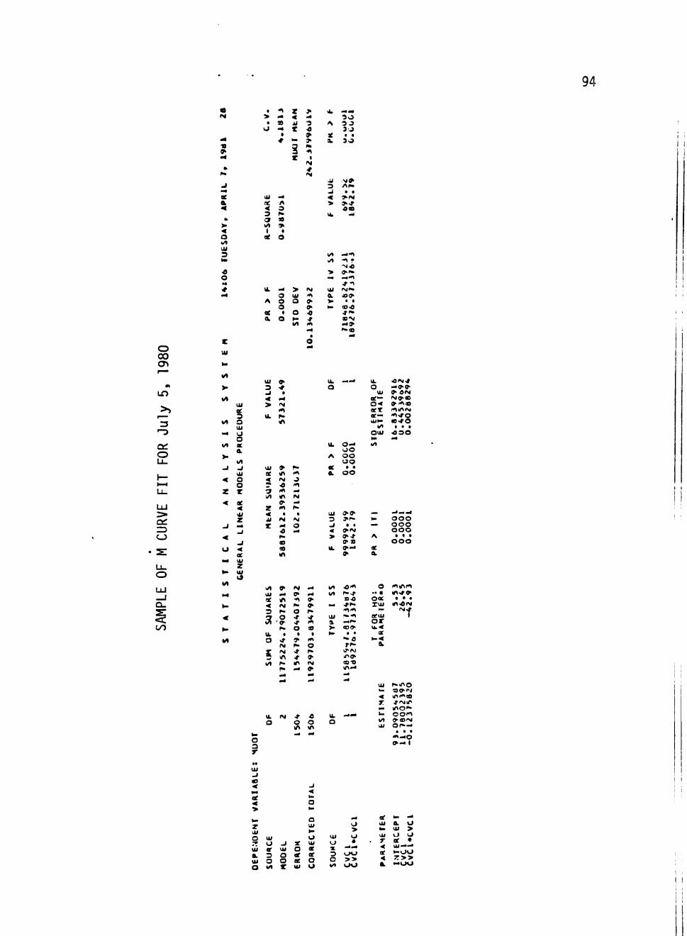
94
• -^ Z * i — • > — < ^ 3 0 • » i i 3 A 3 3
<J -^ t -e 3 J • » X • •
•* — > a, 30
•4
.J . 4 oe & < »
> < o >/• Ui 3 «• <0
o M
•# . 4
Ui ne
< 3 9 I / l 1
X
Ik
A
ee a
. 4 A O r»
« » • o
. 4
O
o o t
o
3 X
> U i
o o I/l
4| I
IM
(M
IM 41 0-
> •0 -r —
^ 3
< > vk
I / l >/l
> m^
Ui a
> »—
M » n i »
• • > I M > . f O S
^
.441
9 ^ ^ — 41 •t-^ rsii" d O ^
t • O 'O 4 - I * • •M — »
o CO
Ul
•-3
o
u_
UJ
CJ
LL.
o U J _ l ex. 0 0
> «A
<A
. 4
1/1
>. - 1
< z <
- 1
< o . M
• B
Ul oe 3 S Ui
8 ee a
I / l
^ Ui
o o z ae
« Ui
z . 4 - 1
^ oe Ul
z Ul
Ui 3 .J
< > Ik
Ui ee
< .» 3 1/1
Z 4 JJ
z
» •
. 4 IM <*l r» in
» in IM •0 m m 9-m
• » •i4 •0
Ml
h-4 1
o "> . 4 IM . 4 r .
• M
o . 4
I k
o
Ik
A
oe a
. . . 4
0 . 4 O O O O O O • « O O
I k
o U l ee— o < eeT ae— o i f .
i/> O U I k . I / l
' O I M ^ — 9 .9 . ^ 0 » M I M ^ B 9 i « i « r<lin«M 4 i « r o C ' ^ O
• . • 4 3 0 . 4
Ui 3 . 1
< > I k
<>» > r -
• • * I M V'-t » S ^ - 4
»
— ^ . . A
« a.
• ^ . . . a 0 0 0 0 0 0 0 0 0
• • • 0 0 0
M
^ g> IM — 1/1 •O'^ O 4 i i n r t Hi — 0> — IA r-.t " « * ! • * » X ifS -fl 9- = 0 O * • • • < IM 0 . 9 . . . . ^ r . x u i m ^ i M 3 r- O r» •^'^ - ' ^ f C» O «!• •* Ul ^ * » X<1J I iS • » >r 1*1 a —' o x
r . o 9 ^ ^ o i k < I k l ' l » » • • of O <f ^ I " " f l • - ?
IM f«. O ' ^ ^
S IM -» f» " ' ^ _ in r » ^ » I/l p- m IM OS'S
Pi ^ » i n . 4
a 4' o u. 0 0 o m Ml
o 3 r
Ui
*. < X .. u WI Ui
r-ino •^<^'>i i n ^ B ^iMin inc" o o « ^ C M O r — . • • <»«—0
o>— 1
111 - I 03 < ee
>
z Ul o
'<
a Ui
lU O Ui o -< X Ui o
Ui or Ul o * * a 3 o ee ee 3 Ul 3 O oe o o O «/i Z Ui o •«
o > o •
i 4 . .
0 0
>>
ee to — Ul a o » . Ui > Ui o o T ee • < Ui — ae ^<JU < T>> a —00
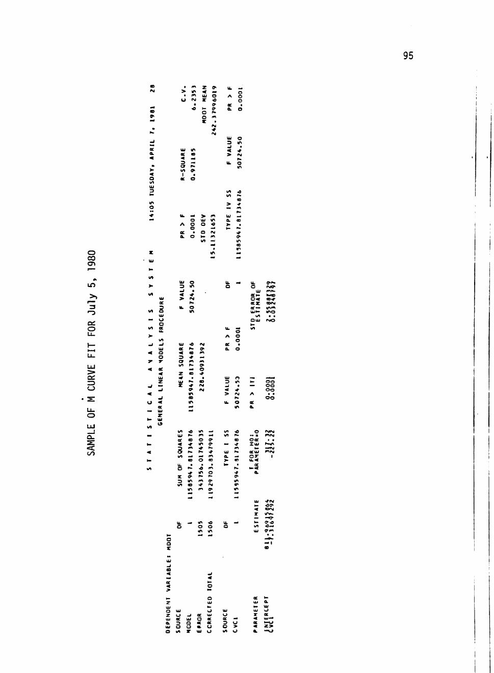
95
« I M
. 4
V
»• ^ » .
U
*• ee & < • >•
< o I / l U l 3 • .
M l
o • •
• • . 4
. > . u
U i
oe 4 3 o I / l 1
oe
I k
A
ee a
w Ml 4 1 IM
a
«
m m . 4 • ^
r*
* a O
^ O O O
• o
z < U i X
• -
o o z
> U i
o a to I/l
0>
.. o •c 9 9-f . 4 1
IM •t IM
I t Ml
<« .. IM 41
I k
A
oe 0 .
U i 3 .J
< > I k
U l IA
> ^ U l
a > to
. 1 .
o o o . o
o Ml
. •4 fM r . O Ml
•C
OB
* m f . « 4
o
. pte
* 8
59
o CO
cn IT)
•-3
oe: o
UJ
Z3 CJ
OO
> I / l
WI
** Wl
> ,J
< ^ <
. 1
< o
to
Wl
.. to
•* to
I / l
U l
ae E U l
O
o QC 4k
I / l - 1 U i o o y
ee U i Z . 1 .
. 1
^ 4 oe Ul z Ul IS
to O o z
U i 3 . J
< > I k
U l
ae 3
a IA z « U i
z
Wl U l oe
« § Wl
I k O
X 3 Wl
I k O
O Ml
a * r g p . O M l
« r. 03
| 4 |
o
. >.. * 9 Ml
Ml .14
<e r>»
« •r (« i i » • ^
s
. -•* a
Ml
11
58
^
»M
» I t
"1 9 o
a St «M •M
m m O Ml • • ^ . 4
o •
« Ml
^ m
m
o Ml . 4
^ . 4
W 0>
!>. •t m eo
. I t O ^ •
S"
1 19
2
•o O Ml . 4
U i
o
t k
A
ee a
U i 3
^ < > t k
w» Wl
.. U i
a > >-
n. o
. M
o o o
a
O
« Ml a
•*•
(M 1^ O Ml
<o »«. 03 >f 4 1 p .
.. m
. p -
•* 9-Ml
Ml
^
I k
o Ui OCto
o < aez ae — Uito
Wl O U i to I / l
^ ^ A
oe ai
O •• n Ooe Z u i
h .
OCUi
o x U i <
oe to<
a i
MA
TE
to I/l Ui
0>». IMO» ft^» l w « a>«r « < M i n t M I O
. . I M O
1 •
O O O O O O
O O
IMiM I t I M
• . r . « i —tM I t I M
1
<flM <O0^ axM
—w 9-0
. . #
— » «
CO
ee <
O Ui Z O - I
3
a o C3
O Ui Ul O OC oe — oe 3 o u O > O Wl o
ee to Hi a to Ui I i i o r oe
« z >
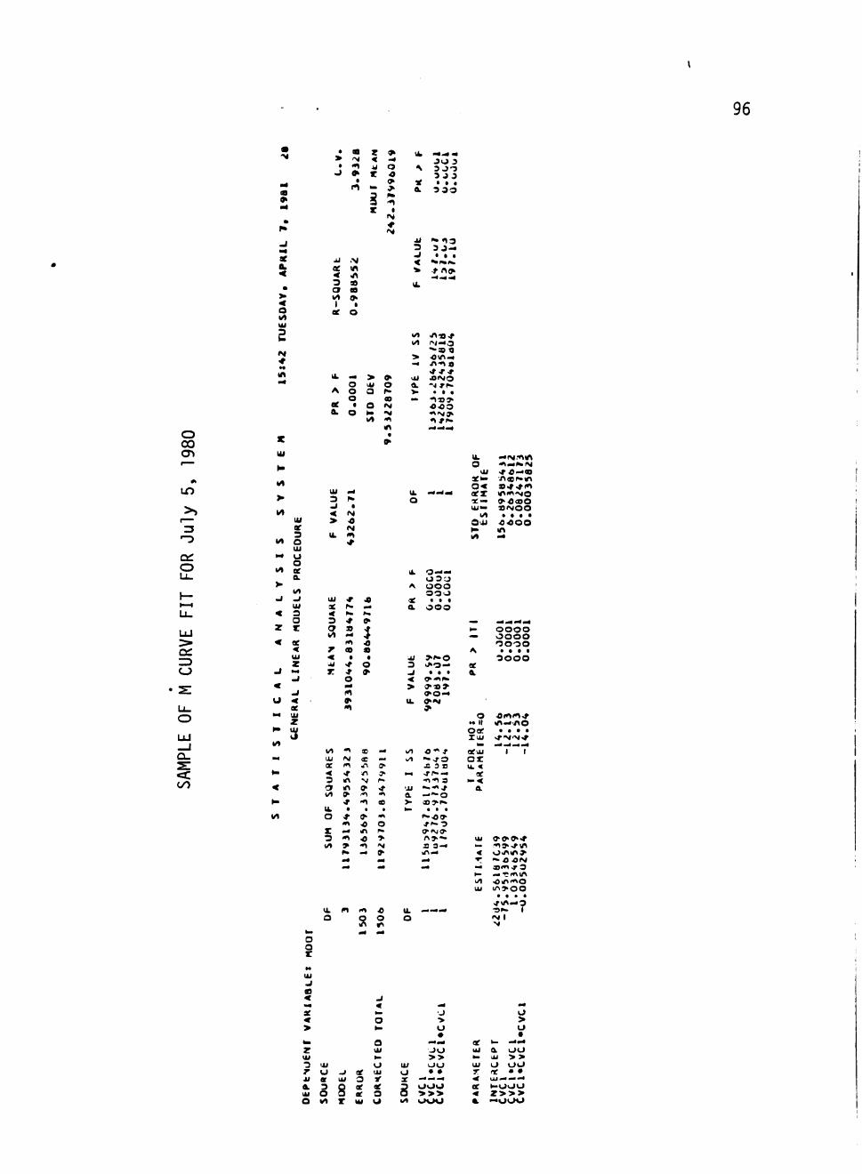
96
X a.
o lA U i
I M
a
> a i J
i i oe < 3 3 I / l 1
ee
a i M
4 1
» • rt
N in Ml 9 a >
i O
z < i i X
HU
Uf
9
^ o « > 4 1
t
IM
I M
I k
N
X a
i i
3 .J < ^ Ik
• ^ i r f ^ 3 0 3 3 J O 3 3 3 • a a
3 3 0
n. « i3 3 3 -• a a
^ t a ^
^rto»
o CO cn
uo
o
U-
Wl J^-B^t I/l i ^ i—O
> om— — n-n a
I k — > ^ u i A I M O O U i O fti - i ^ r .
A O Q P . ^ . a a O « — t U f f .
ee • o fM O'Oo fti O ^ "M « l " g a »
w l 41 .^ ^ ^ Ml — —
CJ
IA
IA U i oe 3
Wl o Ui
M O o Wl ae a
wl . 1 - I
U l < 3
O z z < ae
.J — .1
< .1
o < ee
. 4 Ui
z
Ui «4
3 r» . i a < (M > «
(M Ui m
Ul . r « ae p- — < l b r . 3 «r »• 3 S .» I / l — ^
41 iD z « a < • • ii «f o T -t 9
O • 4
"1
I k
o
u. o
U i X t o
o< — ' — aex
9C — U i —
Wl O U i
^
— IM.41M> ^ — I t e l M
^« —« •nsr-Mi » * ^ i * » M l l t ^ O >0<oO aiMoo
. a a a 0 4 0 0 Ml
Ui o — — 0 3 ' - 3
A O O O OO'J
X • • a a ooo
Ui > ^ 0 3 i > 0 — - I t a . < ^ 4 1 ^ > * » >
O O — U. » > M
to O O O O — oooo
oooo A . a a a
3 0 0 0 ae a
o omm^ n II Ml—no Otf . . a a lUi >r^ 'N'*
<: OO
Wl "1 Ol IM ae It
I / l O ' « — k/i
n ^ M 3 m N 3 m » ^ I/l » t t
* t o Ik • . . o * »• t
( t iO o X — Ml ^ 3 41 « » Wl » 41 ^ . — »
O'" r aeoi "--ro o x X 3 r Ui <
srr-— ae - t t 3 to<
'ii — • t ^ a a —i^o ^ . . .
r > » — Ui
a 3— — M l — <
I/l U l
I I
u. o
« 4 1
8 u. — — o
99'9-r t > , f Ml o.nMi» "» O O M a»<t.r O . . • ' C f t m • O r f i t o i / ^ > 0 0 . . . .
>f<n—3 •3P» T « M l M
3 O X
. 1
U i
. J
< . 4
> to O Z Ui U l to 3 Ul o 7 o - i ae Ul i i or Ui 3 IT
• J > O
J O >>
111 O O o • • X - • — -
o > •
ae to —.4 ui a O O to U i > > Ui O IJU T X » • < UJ — — — a 3 o oe ae 3 UIJIJ X h-u\ju
Ui O 5 oe O O > > > O Wl X Ul U Wl KJ\J\J < z > > > a —ooo
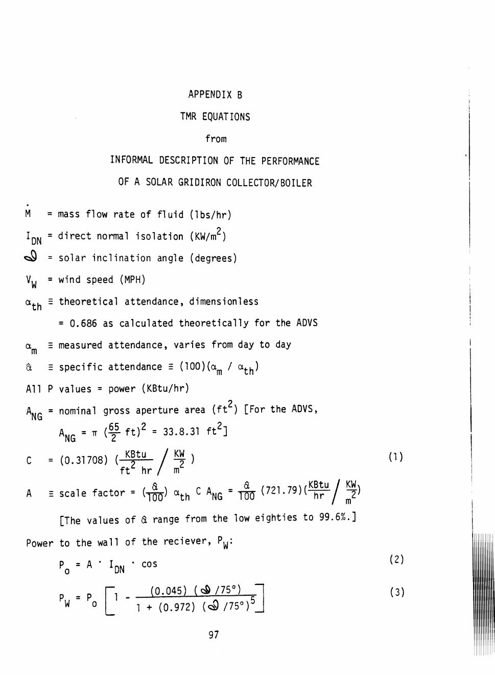
APPENDIX B
TMR EQUATIONS
from
INFORMAL DESCRIPTION OF THE PERFORMANCE
OF A SOLAR GRIDIRON COLLECTOR/BOILER
M = mass flow rate of fluid (Ibs/hr)
111 = direct normal isolation (KW/m )
^ = solar inclination angle (degrees)
V^ = wind speed (MPH)
ct.. = theoretical attendance, dimensionless
= 0.686 as calculated theoretically for the ADVS
a E measured attendance, varies from day to day
a E specific attendance E (100)(a^ / a^^)
All P values = power (KBtu/hr)
A.,p = nominal gross aperture area (ft ) [For the ADVS, 'NG
^NG " "" (y-^^)^ = 33-S-3^ ^ ^
C = (0.31708) (-^^/^) ft hr / m
, 6L \ r A Ct /701 -7o\/KBtu / KWi
A = scale factor = ( ^ a ^ ^ ^NG " I W ^ '' ^^^"hT*/ T ^
[The values of 6L range from the low eighties to 99.6%.]
Power to the wall of the reciever, P^:
Po = ^ * ^DN • '''
P = P ^W 0
1 -(0.045) ( Q & / 7 5 ° )
1 + (0.972) ( C 3 / 7 5 ° ) ^ _
97
(1)
(2)
(3)
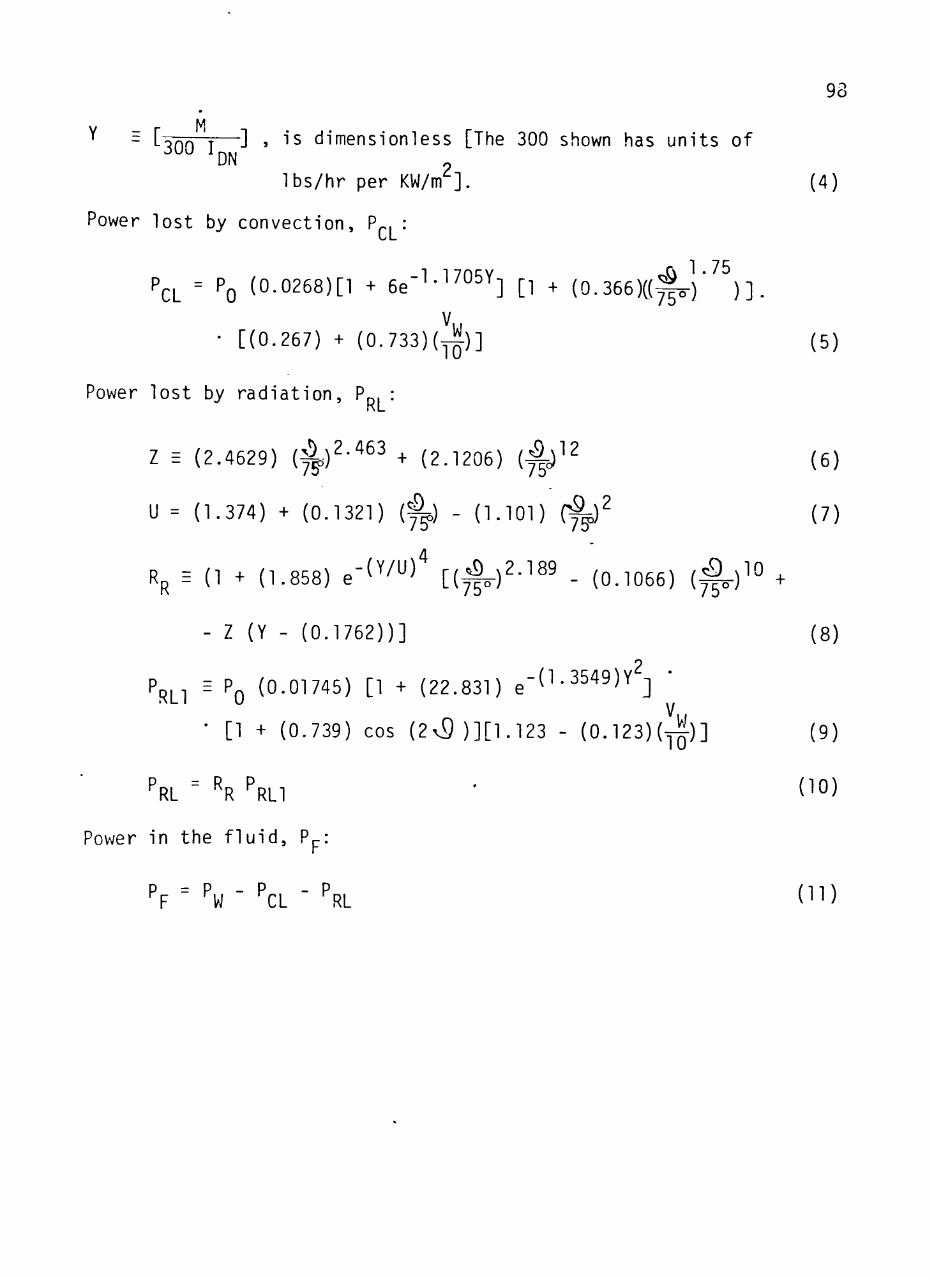
93
M ~ L'^fifri—^ » "" dimensionless [The 300 shown has units of
Ibs/hr per KW/m ].
Power lost by convection, P , :
1.75 P^L = PQ (0-0268)[1 + 6e'''-^^°^Y] [1 + (0.366)C(^) )]
V • [(0.267) + ( 0 . 7 3 3 ) ( ^ ) ]
(4)
(5)
Power lost by radiation, P RL
Z E
U =
= (2.4629) (4)^-^^^ + (2.1206) (4c)^^ 7? 75 ^
(1.374) + (0.1321) ( ) - (l.lOl) (f^y
(6)
(7)
^R^ (lMl.858)e-(Y/U) [(^)2.189. (,_ 066) (^)^° .
75<
RLl
- Z (Y - (0.1762))]
2 E PQ (0.01745) [1 + (22.831) g"'^'^^^^'^ ]
• [1 + (0.739) cos (2v9)][1.123 - (0.123)(^)] V
(8)
(9)
PRL ^R PRLI (10)
Power in the fluid, Ppi
P = P - P - P ^F W CL RL (11)
mWm
APPENDIX C
STEAM TABLE CURVE FITS
99
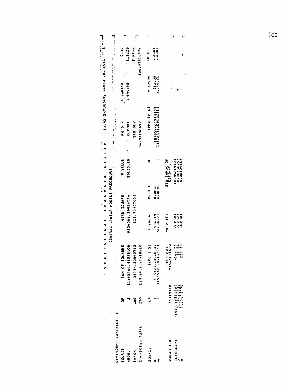
r » . - • — - ^ 100
1 -o ; 1
1 ;
• — ' S
. «^ ' . 4
. ' M (M 1
s ; : O '
« < , z ' • - > •
< . a
X 3 to
< Wl
I t
.r «. •>. —
• i
' z . U l
1
>' a • O
1
•
I
i I U i
1 rr < 3 . 7 Wl 1
ee
» • 1 I k 1
A
oe k a .
•
.
I t (M (M
r» • 4 4
'
n 9' 9
» a O
• o o o a O
( .
J Z :
<<. U i ' Z '
^> '
> U l
a o to Wt
-r f " i >
o ^ 4
• /
f "
> a O o
f^
IM O >r o 9 . 4 . t
a
mm
i L
S
X X
U 3 J
< > k
Wl v l
>
u a ^ ^
^ - O O 3 3
O Q a a
3 i 3
-3 — rt'M a a
n o — c ^ 91 0
•<i
0 — • * —
••• . i * \ i
r — j - o • i O
• « -r — i f r -33i-» — O « i - J — i A
«i4 * 4
nt Ui
3 / lit a
Ul M O
o VI ae
a Wl
.J . 1 ' Ul
< a o •
z z
Ul z
J — J
J u <
ne
Ui O 3 M .1 • < o > ft
. 4 IL <4
M
Ul ^ I t ae Ml ( t 4 11 'O 3 o r» r» I t in Wl o t
» o
I k
a
I k
A
X a
• . 4 . 4
3 C 0 3 O O
a . O O
I k
o i l
ae— 3 « XX ae— U i t o
Wl 3 u i
^ Wl
i t i M r -> O i n to^tt ^ O * . 4 411%! O - t f . •noo o o o
. a .
o o o . 4
z <
M iM a IM
O IM
M
a Ml
'« » — 2 — ' i J • • < -r a > o >
i n o Ik —
.n
to c o o — C * ' 3 0
O O O A a a .
O O O X
z Ul
Wl 03 IM O Ui O .4 M ae — f » < in Ml a 3 1^ - f - • Ct o a> > wt • as I t —
Ml IM s tk . . a • o -f - B
o in — z — »* ^ 3 M »• — I/l Ml m —
i/i " •— wt o —
— O ' M r-t
'U !^ — a »?> ^ r o . 4 * *
4 \ . 4
f i . i41
MIO
— m
O « i O ^ •" II r^iMi^ o.< • • • XUi O B ^
to .riMM ne'U — IM ox t Ui 4
X to<
a
U. IM Ol O Ik — a o p . 3
-.J iM
• U - « — O to n"!!*"
r ——"M — O f i i " to ^ - - tao wl a o u i Ul O O O
. . . — o — a n
I
B
X
>
J
k .
z i i
o z u a i l o
U i LJ af
3 w l
J U i
HO
O
ae O
X U l
3
CT
c
U l
- ae
o
u 1. >
a 3 3 wt a Z
ae u
to 11
< oe * a
to
i i o r '11
z - l i X
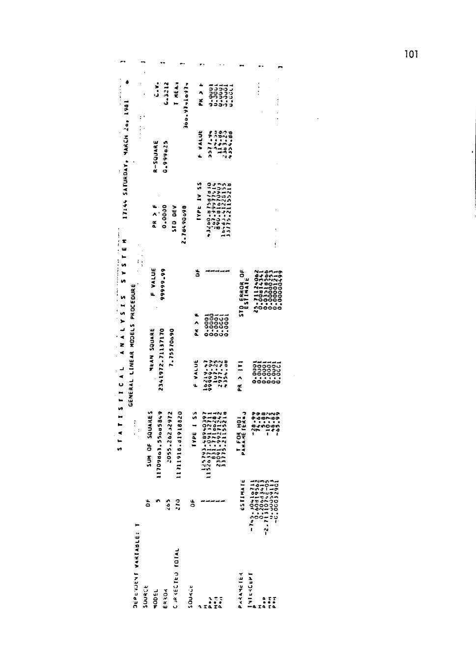
101
B 9
* : ! • * ! : oooo J ,\ Zi ti Z ' 300 30 i j <t « 0 3 0 3 0 0
. J _ " t * a a a a a
o
X
o T
•< O se 3 to
<
•r
Ul Ml ae «» < a 3 ^ or » Wl o I a
ae o
Ik o > « o Ul *
A O O O O O
ae • a » Oi O to ^
Wl a
3 > . ' ^ t»»M'a •J • a a a a < * * f * i t i ^
> ^'t—on -n .4 ' t t
Ik n r^f
wt O ^ f t ^ / ^ J 0 Wl •" — O (/I . .
» . ! « > - I M > •>•^•0^.•JV1 — » ^ ^ • i ( M n
n > OiM — i l ^ O — M « < X a - M S - r i M V a a a a a to o f » o - i n
O 0 » - o r -M - i « f . -41 a - t # — t
(M
1 3.
.* Vt
t
' Wt
' Wt
' V
. J
• <
z <
J
<
u mm
to
Wt
» 4
• "
<
w Wl
Ul oe 3 a Ul o o ae a i
1 ^ mJ U l
s z ee < U l
z w« J
- i < ae Ul z Ul 13
*
.
UJ
mj < >
Ik
U i
ae < 3 3 wt
Z < M
r
wt U i X < 3 a I / l
Vk O
z 3 wt
« O"
a
9 9' ^
O f"
i t . 4 . 4
. (M ^• ff> . 4
I t
9> ^ 03 Ml
a 0
Ml Ml
. 41 0 s » o
o »> 0 o Ml Ml
a
^•
(M ^ 9 <M t
(M
o IM
• in Ml
o " i
o N a 00 . 4
» . 4
•o .
'O m* (?
.« ^
u. 3
I k
A
X a i
U l 3 J
< > ' k
' / I wt
«— U l X > ^
. 4 W . . 4 . 4 . 4
— o — — — O O O O O o o o o o O O O O O
a a . . a O O O O O
l » » M l f M » * ^ I M if O . . . . .
5 > O i * r » ^ -'9 3 ^ i n i M < r — 9 ' i t O0> IM .f — o
f» — — M » * — f l B ' . r — ^t^. 'MPJIM OfM 0 —Ml . f t O I^Ml c ^ — > v i _ . rS^I**9^ ^ f O f ^ ^ i M a . a a «
( t . . . 4 . 4 M l » r » < t » r " ^|*^^t^r* ^ O l t < t M ^ IM I t —m
I k O
J i aeto o < XX ae — Uito
Wt Q u i
wt
. . ^ . . A
a i
3 • . N O-X Z U I
h .
arui O T I k ' *
X to.<
a
M > . 4 ( t i . 4 9 > O ^ O M l —0> O i t M l M f M ^
*«f ao—o I M . 4 . . Q O Q —anooo — O i t O O O ^ O O O O O
1 0 0 0 0 0 IM
— — — — . 4 O O O O O O 3 3 O O 0 O O O O O O O
a a a a . . O O O O O O
» 9 0OM(MO' »'««^•(a9
• a a a a a <l<rM10<OMl iMr« — i f o 1 1 1
u.
a Ml O N
Ik o
' i l . 4 ^ 1 ^ 4 1 ^ . 4 to — o — o — o < r » m . t t — ^ X O ^ t i u i ^ ' J . 4 . ^ . . f ^ >f J 1 . 1 to J ' T J O ^ - O O wl OOOOOO 'U t ^ , M . . 3 o
. a . 4 1 . .
n e o — 3 ' j
I IM I
1)
. 4 X « >
J
n T U
a i l
f )
XI ' , 1
ar 3 3 wt
_l Ul
o o r
r o iV
or Ui
1.1 U l 1<
X
-> o
u •J
r 3 a I / l
1 r r • • • 1 ra ra
u r < f • <
a
o nf u - a rr ^ • • • —a za ra
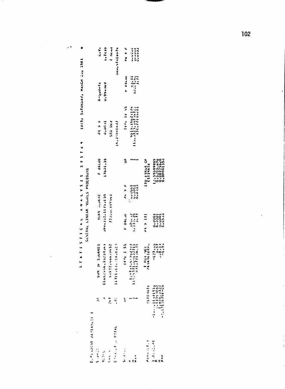
102
a
^ V 1 ^ • 4
» • t
••I
r u < < z » ^ < 3 X 3 to 4
W l
M Ml •a a . 4
X
i l
a
> t
• J
u t X 3 * . ' 1 ae
i k
A
i r
I i
t\ t
^ i «
• ^
'> 0
> r > 9
a
3
. 4
^ o 3
a
*.%
• •
( U
r ..
» i i
3
3
I / l
•r 1 ^
» a ^ r • ^ a 5 9 o
.<. t
0 . 4
» n
• t a
X
A
X a
U 3 J t
'> k
• y i
y
•>
I I !1 a .
^
-« 4 1 •» 3 t
• J 3 / I 3 1 3
9 9 •
» t'-i
— J * .
— r' * • t t ^ - t r - i
• i
' 1 n
.» 1 — "" wrs . . ^ V •1 / I fl
IM - B
or- — i l > C ^ — 1 . .
. a a 4 1 ^ . . . — < N l t n i » - t i
4
m*
> I / l
W t
ta4
W t
> . J
« Z
•<
J
< o to
^ l / »
. a .
« to
• / I
U i
• 3
a U l o a 0/
a • > i
J ' U •3 a — oe ' i i
z .. J
J
ne U l
u
' i l
3 J
<< • >
I k
l U y
« 3 r
c
< : i
^
1/1 U l
X
< 3 11
w t
k - 1
r 3 ' / I
u. ' 1
U l
I t a
. 4
o o ^ . 4
c i t
mm • ^
/ I
.. a
/ " I • t
• t
f
X t
;* • r <1
4 .
n ••1 n
I t a
o '/• ;. - 1
f l
0 mm
mm
1
n r (1
^ ,-#1
t
5 a
- T 1*1
t i
t l
( t
.f
^ ^ 0 0 r . H I
A t
l /» T n
^ 0
*".• "•I 1
IO
. f
*. -• .
* ^ % . 4
- 4
'. / 1
I k
3
•L
A
t
\
•il 1 J
< > ' i k
W l
W l
^ u
^ ^ •»
L 3
-m^^
— — I t J O t O O ' -•.>oo
a a a
3 3 3 i - -
"
M i l " * -1411*
. . . J - 1 t
t i ' ^ i •1 11
^^. . • ^ ^ i . *
" f " . 1
0 » l 0 r - t -» / ^ ^
^ - * • ^ "
>r 3 - * . . . ^ ^mm
« i ^ 4« f**". r> e. r •1 • !
• 4
. . - . i ^
I k
o 'U i T t o
3 4 XT rf— j y t o
Wl 3 u i
• / I
^ k .
mm
A
1 .
J
•. n O T f TU
.. •Y U J T •x«
V
to<
1 .
u
.. • 1 '
Ml O O O ^ f - ' M M l ( ^ O ' O ' t 9 l « « . 4 » i t i " l O
notoc M l - i l O C
'nooo a a a a
" l O O O . 4
^ . . . 4 - t
O O O t ooo.n O O 3 0
a . . a 0 0 3 U
f h - t f • • n i t ^ a a . a
^ i 3 a > . 4 i-i - 1 1 — 1 1
3 M ' « i n — O - T J C l l ' t 1
"*• T' l-f r-f^ a "
. . • t i . l . ^
. . . i j O ' . i
<1
I
u W l o Mt i t a
1 n
.1 , 1
r .1
• * to
•e
^ —axAi
103
'«
i ^
<o (^ •M t
* a r i
X u ae < X
• V < o oe 3 to • <
Wl
in i f
• • f-. 4
a >
a 1 O
,
Ul ^ < 3
wt 1
X
I
tk
A
ae a.
r* 0 ><* mm
a 3
. 4
f ^
* a O
o o o o a O
-» • <
4
X
^
> U i
a a IA
t *. • *
a mm r Pm >
a
a a 1 0
• 0 0 •r r^ •t
o
k — — - - 4 — _ . I ^ 3 0 3 0 3 0 3 0
A O J J 0 3 i n o ' 3 0 3 0 3 3 3 0
X a a a a a a a a a 0 3 0 3 0 J 3 < 3
3 0 ^ I 3 I M * » a o — J . a a . a a a a < i M O , r — O O t i t > a — — f » 3 0 O
I k
wt ^ — - k i y f l l M •A O 0 ^ — O O
O — 0 - . o o > > « n > a . r 3 j . . p . i n ^ . . . . i ^
U l O I M > f M — O a 3 ^ - i » " " n i y V a . a . • • to , / ^ TJiO t < 0
r » ^ t a j f - ' n n — ^ —
— 0 D 0 — ;il 3 - *
a * a o 3 r -
« a
3 ( 8 — Ml
o
t/t
v t
Ui 3
3 o U i o a ae a
3 o X
U i
z
> • V
I k »
Ul I Ml ^4 ae M M < o o 3 f" 0 3 o >r Wl Ml >
iO — z o o * • • Ui -r IM r o
I t
3 < « X X — U i ^
wt 3 u i
« * 0 ^ — 3 t^^9B9 n i t o o - " a . / IM Q^*^*^mfmm . ^ J D O C M O ^ i t i ^ o i o o noooo BO>r ooo . a . . a a .fOOOOO
0..t •?oo o o o O O O O O O O O O c o o O O O
... OOO
o ft.
to
Wt
a .
^ < h .
< ae U l
z U l
Wl U l X
< 3 o wt
. 4
^ 9> ? O O o (M Ml
.. IM ae f~ Ml » l
0> IM
o l"l
n on -. O mm
ffl
X —o—' — — -"- — O O O O O O — o
A OOOO'JO'nO O O O O O O O O
ae a . . B . . * a a . O O O O O O O O
Ui » ^ . f « 1 0 4 « ' M f " 3 C^ n < i 7 « 0 a — J . * . . . . « . < l » J » ^ « l t ^ 4 \ ^
> - M * — > — O O O " ' a ) » - * ^
k 0 9 CDl^i T O —
i . . a . . . 4 . 4 . . ^ . . ' r ? ' 4 — i O O O J C 3 0 J O — I / 1 3 0 0 0 ? C C 3
0 0 0 0 0 3 0 0 0 A a a . a . . . . *
ooooooooc X
a
Wl
Ul
a , ' o o' f t » —
r IM o • 3 - -W l — —
* . — — i M a ^ o o » — • s . f — o o t P » v J I M I M M I t m Q(M a..'nin>n>f f i t - O P " f\ a ^^ y _•—<•>—in Mif a^r^o—inoo r o ' • • o ' M M O ^ • . . . . . . . .
t—*.i...-noooa y ^ ^ . ^ ^ ^ . o < . 4 ' n '•tac*""^ o n o It t — •vj- i M t
—^
3 •> I I o a e Z U i
<KIU OX It.*
ee to<
a
, f i n . f n . f — o o o i f t I t a ^ u i r - T —
. . . a . . . . . — , f t « . / ^ • — 3 " t I J I I
I s; ?t
U i
I k 3
IM •o CM
o
O ^ o M i r — *-n t "• O i> -r o
< —-M,f I f n I y ^'.-f* u /* •!• " mm o>'ii/> fii." r ." to f T I C ^ ' H — * " Wl — -C Ml ^ ' ^ o o Ul 1 C " - ^ 3 T 1
. . . ^ • • •T •J — — ' ' 1 - ' l
- 1 I - t I O
O 1 I I
I n I
O 1
"J I
J T
< ar 4
>
r ViJ
T 7" u a 11
o
u o •K
3 3 wt
J U i 3 O X
i V
O a' * •
U l
J
.« ^ 3
J i j
to
o -1
I '
-* -1 o
• I I
o •e 3 a wt
C I r • • •
1. rx c-vT a za zazan
Ul
r o 0 /
• • •
a —a ra r-v za 1
APPENDIX D ^
COMPUTER CODE FOR SIMULATION
104
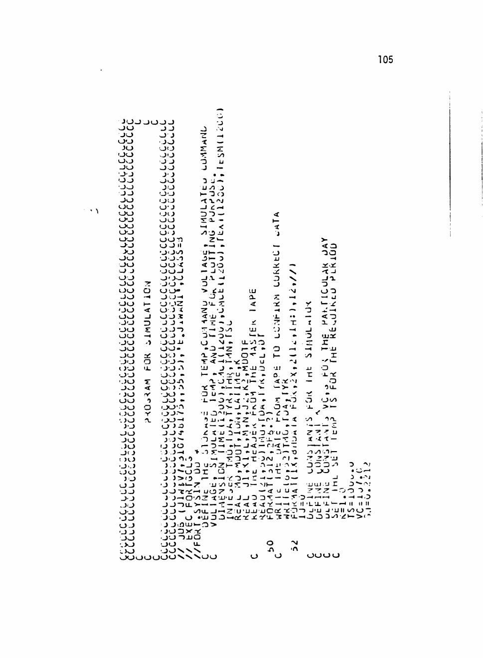
105
J O . J ^ O J - )
J O O O
J O O O O O O O O J
->^
>o
O J O O O O O O
-)o .->o O O
' ^ • ^
- J O J O
' J O O O O O « J O • O O
J O O O J O J O J f J ! ) t J O vJ O O
J O O J J O J J
J O O J O J J O - J O ; . > 0
o
3
3J: o
< iV
o
J J O J J O
J O J J O O J J uu J O
O O O O O J O O O O O O O i J o o r j O J •• O ' J V l O J^ ' )
uu t O O - i O ' J O J O •
uw 0 ' 0 - 4 O ' J Z O J X UUJC J J -•
O J - > O J • o o x i o o -O ' - ) •• J J — • J O .'v O J -UU-Ti O J '" J O -
uu -i j o ' n I J J ^ -j u - t
O J O J J 4 -J J ^
( J J O J J - 4
J O ^^lO i i - J
J j - ^ - o J J > f ! )
O ) -»•— JOTTT: J J - t O
J O - ) U L J J — J O o J J •OUJ J O D V
• J O " ) - u O O J O \ X
J O . si
< —
J —
• •> •3 J —
U 4 0 J - J t : * - *
^ < •t J
LU
'JJ
o
D
J
•a:
o J
I — r •• O"*- O
O. X -< .TC '^i
O O O O O O O Vi>^
'JV-—. J > - 3 < Do I— J ^J _I .V -« D -
O J 3«JL —
^ J <.u • ^ X - J
D > - 0 « - • - » -
- o - « z
UJ J - - s : -u "2
' ^ O T ' ^ ' ^ l t — -jf "XTT •——i:^ 'i-C) u — -— -."r— • 1 . — O T ^ v t ' J O •• ? t - T
- D > - J - j e : i C X ' i . • I I J3'^i>— • • ' • i_ O—« ^ "J
')u.-* -Z'Z. t — r - l . ' — ^ t -X D - " ^ - • • —
- ) J 5 : — • - i T x — " c r i r - o - i - f — j < — r . « h - ~
> ^T 5 " — D CD * U ^ - r j — TD to.4 T T ' r i - ' X 3«N/ <"» -
O n o • . • U - ' O T : " - ^ I— • . - ! < ' - 3 ^ i: _ . ^ — o —
: T U y* U ! « : - 3 — > J > — — to-' - ^ u o ^ ' ^ — < x u u < • / i :Z -t 'JJ'U J O D D * ^ T •>-—I — - r — < < i j ^ - j / — < _ ^ i :
u O U . 0 — ' Z U ' U J J i J C O f T ^ O • ' j j 3 0—to:* )^ JC ': '-»_ : 2 " ? ' x
a U- O ^
^uu o o
— -J
T. i -» _J
"J
>-
-^a
—i
Wi.
o 0 : 3
—• u
OJ
•XI ^
r I—JJ
r o J . ' Y :
o •5 a .
o<y> •J- > • —
< x t -
o
.T y l -T i—
3 c; b '" o ^ J uu • w ^
j j u i . u X J " * - i ^ , ' Z ' T Z — 0 0 "5 •
Il ' L U . ' J - ' — - ^ II II II —i J ' U J ' U l l * / i o ~
o o o o
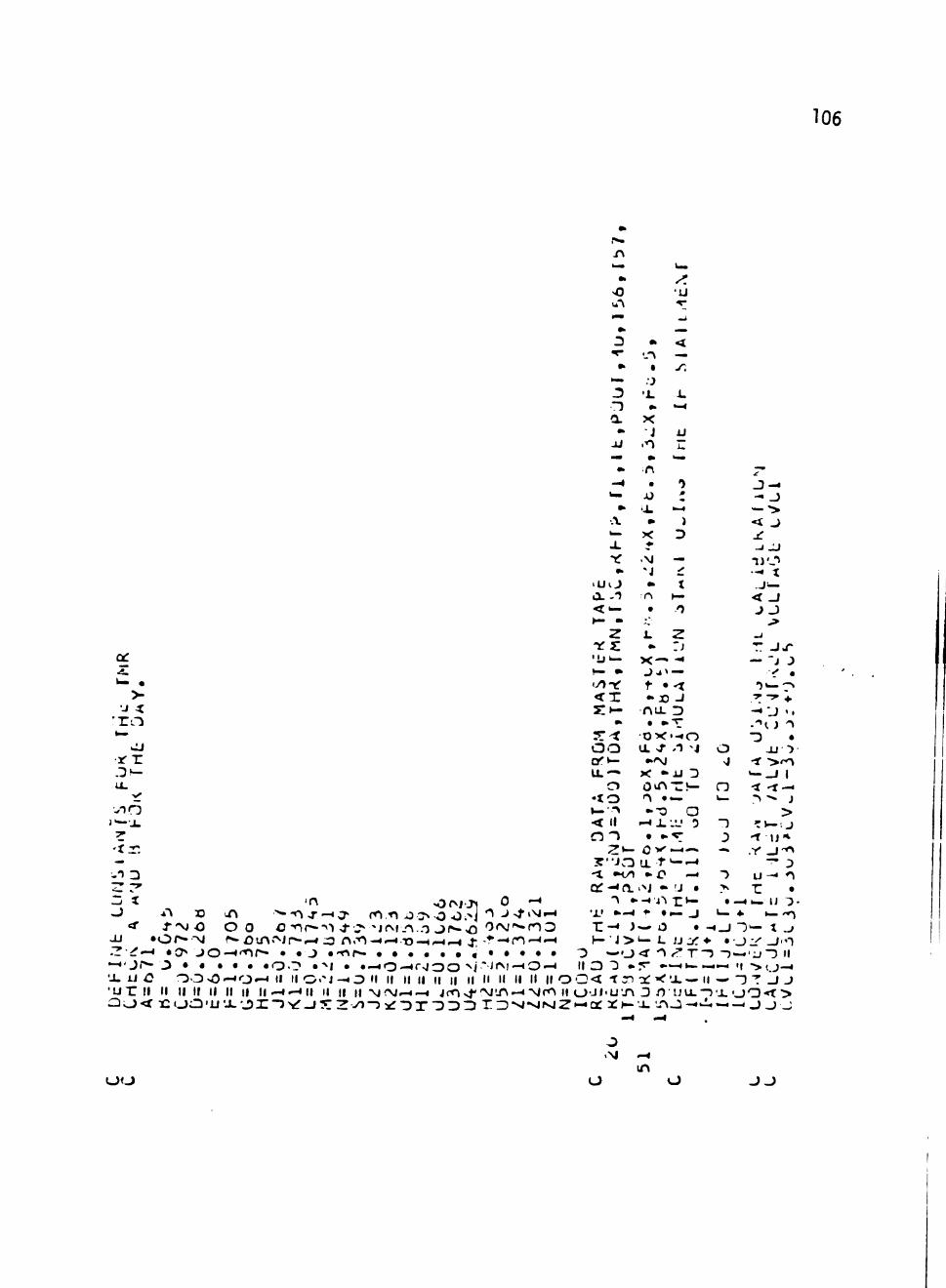
106
•o -u -" r:
» _ :3 • <
- r - . . -^ i ^
* • -/ * - -J
- ) * » - «
-u .n i:
- * • 0 _ 3 - -^ AJ f - . _)
•> .X —• — "> A • ) < J ^ X D J: X • j j j
•xT .VJ — n j o •• N i •-• t
' U O • t J — O. -1 1 h— < J < • - • / ) J J • - • " . >
Z i. 2 -. Ttrs: •• :J T. JX-
CC ' i j i - X - * -« — 'J J -S ^ - • j j i ^ ^ • — • i > O n ^ t » - t •)!——»
>• < X * J D J - ^ - ^ 4 . •J < S IK- r\LL D - « ' J «•
' T O • • • T -' '<.J'> *— "^^ 0 - < ' - « 0 "D •
x r or*— ••'VJ g -1 ^rn Z2^ u . - » K r » u D ' - o i i l . O OvTtTJ- n < - t - i
• t o n » ^ v_ - > ' * j - •
z r' o^-<o. i j ••'J • > r •
o A*\ x3 iTv ^-^j-—«a« ro.-n o:> o Oi^j "^-^^'^•~* '•'-' •—*' • • — J *—• »—'*i <*• f^C O O C'nr-->'> ^ j^^jrvL/^o j(»->o '5r^(i>-n3 r - « J — O • -^o T'— t _»
-u "Or- ' -vj r ou^A' ^Jr to^ i3 n."n-<.-^.-D-^,.^^ ^ - ' ^ - * n — ' " ^ K "J>k—L JJ I / : * - • • j : r '_ i i ' - ) Zld-^ • ( > J O — o ^ r - • - J • - n r - • • • • • • « • • • • • O — O ' i ' "^/^ T"3 -) —'u"!) II —'Ol*** J • • • • • # 0 0 •'^1 • •—*0—<r>ioo ^j ' Jf^ ' -^O-^ II O "3 ••r' ••—I -1—1-4 If •>>, j-_« X IJ O 0 . 0 v 0 - « 0 ^ II II O . ^ J - « 0 II II II II II II II II II II H II O a < - r n c t r X ' X — I I - 4 - 3 T J J 'UTT II II II If II II II II .-4 .- 11 II II II Mrg-^—* jrOxf'NJU^'^Nf^ II 0 'JJ'UT\ D O U X " ) X O Q O ciu< t : o O ' u x ' j ) x ~ 3 v r o 5 : z v i - 3 x : D T ' D D D rz)->»'siNjz»-ia 2C»-x •-rt^-«-i4-.—i _>_)_;
m O O O O J J
107
V)
.V
ti.
p- J ) ^ Z yl ft 'i Z f.nu'X XJ "3 0 h- • z a,*}" —I T -4 — UJrO »-
- - I . O
^ XI -^ -f r<"i UJ -J •oo-f . rT XI
T^ > H • y ) . o < i n D — ^ ^ v i . c T O
(V—•»• u j r * • Oi—I—-^i ir '»-<-CO Z x - J ^ - Q . •• rD -f < o E : a i - » ^ _ i > i '
z •to.sTa.H-otx.-vj • * -J > — 0 U J 5 * " D J " I - I
C/11—'U O l — O J O L I I/) • X l - r j O - J • r -K>J" ' .O .N
j -n iuo Z n - u • ' " D u j < - f • CLQ.—«-'»—-^ O •<1 ST CO
J 2 • — J D O
J • u —< Ol— Ii II AJ
rH.-t Q J O
> > . J J O O O
o
I
.3
O
o
I - ^
z •XI J O I
>r O O
To O kJ
Q J J
Da: * - t ,— iJ »-zx o o ^ ji TTUJO - • > x i / ) 0
D '-I
^ - U J toi4
z>-o O T T O O O D
- 4 0 « / » ' D o o ^ C L O H -c/1 ^ - I II II ti ! i J X I « i < 0 ^ t j - H Q > x T XI f— v l < UJ
o
o 0
^^
.n
J
r 0
X 0
- • O • N. • •XJ OUJ 0<Ni •• i i a > i j y ) Z JJUiT*
I — • — T r - X • — r s i T • T r«-»Q i^j>j -3 v9 O V - i f • — — < a . " — H — ^ ^ " ^ ^ Ot-i
• • O - f ^ r a » rH • • • .-^..^UJ t ' U O U L J > r ' i J > — : | J - « I J J 7 » ' ^ I U J O > - t r ^ — l i ' > r - a J r - 3 i — ** > — X V J > > <'-*< II Z ' - t o - r :^ >f r- o "O O O J'-« J > - a . z J"v. j> ' : _ i - ' ^ a o < ^ j - n u u x i
O II D ") II t i .3 11 D II o—H-«r or "^ cjf—ocVf- II o ^ - o ^ - o II II r II -JO J 2: D Z - I o o a o z .D—z
X X < 0 0 < l in-H < Q < . 0 < "D^XQ p i - i » - » i j a . O h -
'Voo I.DV JifJJ
JJ—
i j j *
^< •3
J <
J -3 >
Q Z
o
xo o
0 3
iJ o > o
z .3
-X o
T
Z
O
1 .
x - » x - ^ i - ^ 0 0 ' . 3 0 <
II • > o O JJOXJ<'JJUO Z ' ) II J > O C L - < > X K I < I a • JO':^xi.'>:^— ^ ^ . - ' ' ^ U O J J . O
u o
o •^•1
—4 •0
o
o
UJ JJ O O 3 l U T H - J • • • : 3 H . < 0 ' - 7 - 7 n
• D J o • 0 * O
N — O - ^ n f - <
• J » O X I - » 0 • - ! • - • \ n — 1 .
XI • - • 0 0 > > > ( / l » ^ ^ T > O t o ^ • •cOVi t - J • - » < 0 ' ^ a . t / l • v I N O D O - * ^ O J O — — 0 < J " ^ - — •c'^oJO—« * O • ' U ^ f X I > * • _ ) « • u . ^ ^ ^ X i V l < ' i J - i O X - ) X " i — * Z J : ^ c r ) N x - n o > C • •> -_D»—iJ?«^OT I to^-i-«0 0
x"/Tj? I t - t - h - + •*• • ^ - < : i c v a f * — •—a.>o ' j 5ox i -3 ' i j < u-^—"^>-••«•> ^'y^ - " — - X O x x i - • t < < ( y o < Z c ^ II I C X I ' o O " ^ I > - " O J _ » > J a . o :t X i j u v i — O ' O r r
" - • — r D ' > • • ' t o ^ O ' / I O II > > " > O H O II "D>-i—"^i— II II II < r-Y.\JOZ Z Z * OQ. ^ l U O O J J O J-f U't-~"-^ II W ^ ' " Z < O a f Z - a — II o - i : — — O ^ J O O II II ' - " D O J - I II
^ j - ^ ^ , . j - 4 _ i « * _ . - *u . i_ i O t — < X X X X I I O I I < " > C L X t i . < < < 0 0 < t t o 4 N / < 3 O ' x ( 3 t o 4 h-h-oa.osTO'^c^'^toH o i / ) o »-(to.i>—iz u > o - - - - -• - • • - • 0 " > J Q . ( j a H ^ _ » t - > - 0 J -
o
o o o o o 0 0 0 o o
108
>
— a: zn o —H mm,
V - - 4
<a Z -n '.'*> -« -r -) o — • O D>f Z O I O ' to4(JJO m^rt ^ L 0 ' / 1 — . •.U "'^
J O ^
- ^ Z D . 3 t o H O
- i . i " ? J
'2 • XI o
T V - 1 - « - t . o
J r\ • v T D l -
- * o — O II
to4<-^
o j - >
J
J *> o .» '_J
J • >
r j K
(> o
u - ->
o • ,r 1 ^ j j
o i ^ >
O J X **
X I • - 0
l - l >
'X J
• j j r y "> -^ /^ r D O O •
• H
•u * r u 1 — J
'.5 0 Z^f ^ t '.n n D A
> ( U • ^ T \
-f r*-OC 1
^ ! ! ? - • O 0 O ' n X •
v f IJ - 0
1— NJ f I M
J II
o •
o II
X
• -3 O TT
—* O
• o •
1— o
• X l _
o -3
D X U J 5 : J t—U J : T >
^^
•<r O o x os:* to4
X a.
.5 Z »-• o z — X
>-33
H - O
D t r O ' L X 1
o 'XI o • - • x
< 1 oz D - « O X J I I < l i l .
o a .
'•
-^ 4 ^
to< r^
' J
o + •
—» —4
.^ .»— z \ Q — 1—1 to^
• !<• >-*
U o • »•
Z - O ^ 'O • - • O O (-0 — a. 3 ^ 3 1
O — - o • 'JJ ^ \ i n * ^ > _ \ U . ' ^ ^ - 4
< Z * - \ o ^ O - 3 "3 toH . - * - D
n—• zawi^ 'y. O II "^ I I -tf I I o z — • II z < 0 II • - • O ' ^ o ^ > j i . a .
o J
a < o
• ^ J
-^ «
^ ^
0
•^ - H
->
»?•
•"•
If-
• — « ' - 4
• J
> •
-^ —» *
-.» >. ^ X 1
to-
.n X oJ • t
' U 4.
• toH
— j j ^ >
» - \ J <: 'r o > 3 II
* 3
a. O O II J ^ < - ?
o t . j
0 > J L
• > j
^ * • ' » •
"-» -^ -0 3 1
> >•— .k i V j
1 • ^
• 'i
—\ » «<
— J
> J
•J
1
T
->
-^ J ..« M.
• • * *
• -f
< ^ j » - i » * . ^ * J —.«.*
H-
—» 3 •
•-•» \ o -. ).r»>co — 3 * - •
m—
.•^
o ^ "5 > »
(^iJ
x: 1
i \ j - 5
"^ • *** " • *
-Vi -< J
.^ 3 •o
• •
i f
. i . k
—. ^ >
V
* "T*
\
O L
X U
•.* ' — - « * | \
• — 1 — »
O ' v J f ^ J ' V . ' V cr' 'V. 1 xx» -»»
i - i l -•XI J — "
•— <
> -» .->i J
O " ^ — 3 o
••. *
I J J — .
•«—•—1
'~ •¥
•
•—• X
o > JL 3 - J
1— - u ' J • i j »
r o J • —• r u > •^ f z
• ' X -T :>•••
•
r \ D
j -
to4':; - 5 X > — " •
N . -
• J Z O Z*-" o ^t——l
3
^ t o
,..( - t »
u l ^ » "3
3 * - » J " ^ X
y -4 x a
_ _ 4 ' - l
i f J 1
o
Z • — • ' 1
T 1—i..^Ziv—
X * 3 "vir
* O O J ^ J J O J ' ' 1 \ -^ " 3 •
» a 1 -3 -^ <
••• M Q T : O
• •^ — < 4 - . ^ II
M : i i3 '^ II ' J
O ' v / 3 I I r v j O O O
< I I II ' X T ' ^
r\ 1
r r
• . H
^ l|
^ 1 X < Z X _ i - . ^
D ^ I I J II t -
O Z 3
<-— 4
^ 1 •^
— D
Tf a : « * X « * - ' 3 0 o 3PSI TC O 'X a o a. J T ^ T -
»_ ."3 J
X I
t _
o J
1
«• a 1
* — AJ
-« -n X —«
u • "> 'NJ < 1 3 — J 3
1J 'J v r .
- J X i t - —
r. ^ ozn X < 0 -1
— - M -
^ Z '^ < 'J J "^ U • f)
— • — - v - 1 O D *
i J U Q . - ^ r •"» J
H - O . " M C ) •3 D
5- X ' • ) o 0 1
r •»— X .-^ D -)
T-^ J •——r~ r - • - T - > x ^ . J - • —
J Z ' J - ) ' 1 < > 3
X • r JJ i"\-» — ^ r J' • I to***, r i
J 1 J - ) ' - '1 T . ) - « y » -J J X X • < n j ' i j 0 w - * - *•
uu uu O O O O O O 0 0 0 0 • J O O J
o
o J
J . 1
3 M
— 3
- • J J ^ - y ) - »
< o o 3 v i r \ IJ r > " > 3 j j ' H O >—'-)ot—H- • : i
i| II M II II H--4
3 3 J 0 3 - Z >U ^U Jfr- 3
— - . — - • ' - EO
•t
u Ji
4 m.
J
Ml . - ' J
^ o o
109
1 i.' —< kJ'— V —' 'T J t . j x ^ - ^ > " : r ixi X I X ^ O O ' — ! - - •
O ^ M O O O m trun
O O o
no
o o z •* 3 3 # #
AJ vl
3 O . J
o
-5 O O < J X • i - ' O ^ r v j * _ J ' ' 3 o 3 0 - 3 . 2 2f • - " - • - ^ < -CO O I j O-* to^-« T » — • ' ••X • • . . ^ •• OUJ z Z • • "^ • 3 J -i-^jr\ • •..-o •'>fN *<Nin - - f l i j j i • s. "3-1 o — —n ' - 3 •2 3 •»• I I j .oAco • " .^ I I •'>}-.jj vjsf • i \ j * n j - ) n -)(0
'-J - > ^ > JJ -UUJ 'OO'^r^ -«»J-UJXl iur |:uon J3,-!-:>-«rO-< O — • — • 'jji-1 'jjto4> J » n^'•'I>-J'.au^ •••0'-*-Njf^4fooa»j"oor-^uj-^'aj >-x " ^ x X " i "^ -^ ^ f ' - i ' - t -c^ ' •T^'-nmr^vom o DcsjOi-nuj > j i j j r o3o • J • 3 h - 3->_o XI :3 r*0 'no-4>ro»r^ ' - i -c .o^ j ' . -H-rNtoo-r \ ;>OH-_j-> j y r I—X h- o • : « • - » -Of-i'Ojo •-«»-^i-«>f JO'jo j5^<Nj.-nin j i 34*-or- 3 x 3 x < J - t O ^ •«/ '•^ Ovr.OrO OOO^ r «3" r —•vAin n o O T \ Xi(r>-r|3T X O I L ^»— 2i— • r, *-' m—i^ j - r* JO o fco>f nc^ o-H(Mto^ o<^»-tinin .oi»'11 * . i
'JLJ — • U • J 3 1- O D r JTO-H A 0 ^ .^ r o M - r ^ - ^ J • J3 . • . - O O 0 3 a x i i n a . x j • 3 jr-i*...—,.— • • • ••JI .NJ,-<NO • • •• J • • "co • - ^ ' - • O ' ^ J t j "D > TrZ^T.Ti "i X uct^^ ov> in -^r * I r I ^ I Al.-^rvjo • r g O i N I 4" I I >/ | - . | . * iii^-i 'Xji-i • -n 1 - ^ ^ . \ I \ \ I Vi • u > 'u->-' - H - Z ' - l - ' D ^ - * Z - ? - 5 - ^ ^ 3 - 5 ^ •X' i • J • J
—.'JJ .—win •. XH-x>-x i—H- X h- X - u ^ o -< J I—-uo t—XII—inx o x o x O J X o x ••••3 • •o — • Z i : « - « Z 3 ••rsj Z Z J J Z U J Z Z U Z tl 3 ' J X O J a . X — t u X - t J O — 3 3 3 3 3 3 3 "3 3 3 Z < i l . u ^ ' l x o z u j o i . —•— to^-),_j-3!j-3-) o -5 o -^—n —a.z
i u < H- "iii J r " o _)"^(V I — o o i — o o i — : s : o o _ j o o o < < < < — O X I ^ 3 U J 3 3 0 0 3 0 0 » - t C r r 3 Z < < < < < l — H- H- >- •>i— "> H-1-0 < < r 0 < < r t : 3 Z 3 • x x i u j u j u j < < < < x l l Z O i i Z ' U a . o o a . o c J 3 : x x X ' i : . 3 : v Q C a i : 3 3 3 Q - t x x j x x v
\j.-o (NJCi -invO fvjfo <Nm >J•^r^o^-c3c^ o o >0 a:
O O lA
Ill
—. • ^
* o X i<)
m
) 3 - . 4 . . ^
> J J - < 3 J — 3 D O •v —
^ O Z O ' ! > ' ' * • 3 - « 3 - 5 v - V — •vO — 3 II Z — r^ . - ^ " D ^ ' j - - ^ ""i-ar J IJ 4i h- 4 •• 1 - ) 0 3
r — O iJ •-) II a. z / T : J
0 3 II • •<n ' U X ^ II
" J : z x -< J < U ' "> J^
u •• - i ' D • O
— O II r» j - <
3 II "> JJ
••"SJ
< • - •
- i . * ) 'xx: J J
-• a X •• • r •i -^
"0 0 i n II - )o •^o • 3 'U
< :t: 3 J • .^
i: II t .o ^ o X 3 v/1 • • • J J- D II 1 O
r> 3
•» i . — < o • O i >——H
< 3 J • ^ f ^
-^ -^ •u •
z — - » J It i .
OL II ' ^ Z - 4 , • )
"3 3 •> »
fV.-* * ^ i — j j
Z ^ ^ • • H > » _ l
•-</>T^ 1 •11 •
Z J 3 J ^ ^ ' / I D II c/> -< -n D 4-a. -z • ' ^ ' / > — i 3 n 3 II ^ O i - D
.4
z - • 3 O O X
Z ' ^ T O Z 1 - V - 5 — J l — 3 ' - * 3 H H II II 3 !l II II 'JmO^Z-^ x 3 ' > - - 5 3 > - > - - 5 t o ^ a . c r - X H-
O l A fOrO
X •
D
o
-o — w O •• 11 3 V •»«' o jt: x i - J - D r O —^3 < 0 II O ' X J J Z
•no-* - 4 < U 0 K a . > • L ^ t / l
• • 3 3 D (J)
X N W W X * ^ W W W > s V . \


![Configuration, Simulation and Process Control Software ... · Configuration, Simulation and Process Control Software Interoperability Bachelor of Engineering Honours [BE(Hons)] Instrumentation](https://static.fdocuments.in/doc/165x107/5e1bc1d7f2bfe86c22028be7/configuration-simulation-and-process-control-software-configuration-simulation.jpg)


![[Luyben] Process Modeling Simulation and Control for Chemical Engineers](https://static.fdocuments.in/doc/165x107/545be701b1af9f131f8b46e9/luyben-process-modeling-simulation-and-control-for-chemical-engineers.jpg)
