Process Simulation and Control Optimization of a Blast ... · PDF fileProcess Simulation and...
21
Process Simulation and Control Optimization of a Blast Furnace Using Classical Thermodynamics Combined to a Direct Search Algorithm JEAN-PHILIPPE HARVEY and AI ¨ MEN E. GHERIBI Several numerical approaches have been proposed in the literature to simulate the behavior of modern blast furnaces: finite volume methods, data-mining models, heat and mass balance models, and classical thermodynamic simulations. Despite this, there is actually no efficient method for evaluating quickly optimal operating parameters of a blast furnace as a function of the iron ore composition, which takes into account all potential chemical reactions that could occur in the system. In the current study, we propose a global simulation strategy of a blast furnace, the 5-unit process simulation. It is based on classical thermodynamic calculations coupled to a direct search algorithm to optimize process parameters. These parameters include the minimum required metallurgical coke consumption as well as the optimal blast chemical composition and the total charge that simultaneously satisfy the overall heat and mass balances of the system. Moreover, a Gibbs free energy function for metallurgical coke is parameterized in the current study and used to fine-tune the simulation of the blast furnace. Optimal operating conditions and predicted output stream properties calculated by the proposed thermodynamic simulation strategy are compared with reference data found in the literature and have proven the validity and high precision of this simulation. DOI: 10.1007/s11663-013-0004-9 Ó The Minerals, Metals & Materials Society and ASM International 2013 I. INTRODUCTION IRON making is the pyrometallurgical process of turning solid iron ore materials into liquid hot metal called pig iron typically saturated with carbon (5 wt pct). The process uses injection of air and metallurgical coke in a counter-current flow reactor called a blast furnace (BF). This is probably one of the metallurgical processes that has captivated the most attention of scientists and engineers in the past. The major chemical reactions occurring in the BF are (1) the combustion of metallurgical coke by hot air (potentially enriched in O 2 ) at the tuyere level, resulting in the production of a CO-rich reducing gas; and (2) the direct and indirect reductions of the iron-rich minerals present in the ore by metallurgical coke and the reducing gas, respectively. The composition of the available iron ore may include impurities such as SiO 2 , Al 2 O 3 ,P 2 O 5 , MgO, CaO, Na 2 O, K 2 O, and S. Minor chemical reactions such as the reduction of these impurities can occur and affect drastically the quality of the final pig iron product, the chemical nature of emissions as well as the productivity of the BF. From a classical thermodynamic standpoint, a BF can be viewed as a complex system in which several local equilibrium states occur, as will be shown in the current study. There are a no. of major phases experimentally observed and considered in the fundamental study of this reactor. The first is the gas phase, which originates from the combustion of metallurgical coke by air at the bottom of the reactor. This results in N 2 - and CO-rich compositions (reducing gas) producing a final exhaust gas consisting mainly of N 2 , CO, CO 2 ,H 2 , and H 2 O. This is a consequence of the reduction of the iron ore. The second set of phases are present in the iron ore which contains iron-rich minerals such as hematite and magnetite, as well as impurities (SiO 2 , Al 2 O 3 , CaO, MgO, Na 2 O, K 2 O, P 2 O 5 , and S) in various solid forms. The third is the metallurgical coke injected at the top of the BF which contains impurities such as ashes, sulfur, and water. The fourth is the flux [CaMg(CO 3 ) 2 , CaO, MgO, and CaF 2 ] also introduced at the top of the BF and used ultimately to remove different impurities. The fifth is the slag which is formed intentionally at the bottom of the BF by introducing fluxes to help in removing undesirable impurities. The sixth is the metal- lic liquid solution (pig iron) which is the final valuable product of the BF. In considering the engineering design of such reactors, refractory materials used to protect the inside of the BF from chemical attack of the different phases can also be considered as important phases. For a given iron ore chemical composition, the control of the quality of the pig iron is assumed to be dictated mainly JEAN-PHILIPPE HARVEY, Ph.D. Postdoctoral Fellow, formerly with the Center for Research in Computational Thermochemistry, Department of Chemical Engineering, E ´ cole Polytechnique de Mon- tre´ al, C.P. 6079, Station Downtown, Montre´ al, QC H3C 3A7, Canada, is now with the Geological and Earth Planetary Sciences Division, California Institute of Technology, Pasadena, CA. Contact e-mail: [email protected]. AI ¨ MEN E. GHERIBI, Ph.D. Research Fel- low, is with Center for Research in Computational Thermochemistry, Department of Chemical Engineering, E ´ cole Polytechnique de Mon- tre´ al. Manuscript submitted July 18, 2013. Article published online December 12, 2013. METALLURGICAL AND MATERIALS TRANSACTIONS B VOLUME 45B, FEBRUARY 2014—307
Transcript of Process Simulation and Control Optimization of a Blast ... · PDF fileProcess Simulation and...

Process Simulation and Control Optimization of a Blast FurnaceUsing Classical Thermodynamics Combined to a Direct SearchAlgorithm
JEAN-PHILIPPE HARVEY and AIMEN E. GHERIBI
Several numerical approaches have been proposed in the literature to simulate the behavior ofmodern blast furnaces: finite volume methods, data-mining models, heat and mass balancemodels, and classical thermodynamic simulations. Despite this, there is actually no efficientmethod for evaluating quickly optimal operating parameters of a blast furnace as a function ofthe iron ore composition, which takes into account all potential chemical reactions that couldoccur in the system. In the current study, we propose a global simulation strategy of a blastfurnace, the 5-unit process simulation. It is based on classical thermodynamic calculationscoupled to a direct search algorithm to optimize process parameters. These parameters includethe minimum required metallurgical coke consumption as well as the optimal blast chemicalcomposition and the total charge that simultaneously satisfy the overall heat and mass balancesof the system. Moreover, a Gibbs free energy function for metallurgical coke is parameterized inthe current study and used to fine-tune the simulation of the blast furnace. Optimal operatingconditions and predicted output stream properties calculated by the proposed thermodynamicsimulation strategy are compared with reference data found in the literature and have proventhe validity and high precision of this simulation.
DOI: 10.1007/s11663-013-0004-9� The Minerals, Metals & Materials Society and ASM International 2013
I. INTRODUCTION
IRON making is the pyrometallurgical process ofturning solid iron ore materials into liquid hot metalcalled pig iron typically saturated with carbon(�5 wt pct). The process uses injection of air andmetallurgical coke in a counter-current flow reactorcalled a blast furnace (BF). This is probably one of themetallurgical processes that has captivated the mostattention of scientists and engineers in the past. Themajor chemical reactions occurring in the BF are (1) thecombustion of metallurgical coke by hot air (potentiallyenriched in O2) at the tuyere level, resulting in theproduction of a CO-rich reducing gas; and (2) the directand indirect reductions of the iron-rich minerals presentin the ore by metallurgical coke and the reducing gas,respectively. The composition of the available iron oremay include impurities such as SiO2, Al2O3, P2O5, MgO,CaO, Na2O, K2O, and S. Minor chemical reactions suchas the reduction of these impurities can occur and affectdrastically the quality of the final pig iron product, the
chemical nature of emissions as well as the productivityof the BF.From a classical thermodynamic standpoint, a BF can
be viewed as a complex system in which several localequilibrium states occur, as will be shown in the currentstudy. There are a no. of major phases experimentallyobserved and considered in the fundamental study ofthis reactor. The first is the gas phase, which originatesfrom the combustion of metallurgical coke by air at thebottom of the reactor. This results in N2- and CO-richcompositions (reducing gas) producing a final exhaustgas consisting mainly of N2, CO, CO2, H2, and H2O.This is a consequence of the reduction of the iron ore.The second set of phases are present in the iron orewhich contains iron-rich minerals such as hematite andmagnetite, as well as impurities (SiO2, Al2O3, CaO,MgO, Na2O, K2O, P2O5, and S) in various solid forms.The third is the metallurgical coke injected at the top ofthe BF which contains impurities such as ashes, sulfur,and water. The fourth is the flux [CaMg(CO3)2, CaO,MgO, and CaF2] also introduced at the top of the BFand used ultimately to remove different impurities. Thefifth is the slag which is formed intentionally at thebottom of the BF by introducing fluxes to help inremoving undesirable impurities. The sixth is the metal-lic liquid solution (pig iron) which is the final valuableproduct of the BF. In considering the engineering designof such reactors, refractory materials used to protect theinside of the BF from chemical attack of the differentphases can also be considered as important phases. Fora given iron ore chemical composition, the control of thequality of the pig iron is assumed to be dictated mainly
JEAN-PHILIPPE HARVEY, Ph.D. Postdoctoral Fellow, formerlywith the Center for Research in Computational Thermochemistry,Department of Chemical Engineering, Ecole Polytechnique de Mon-treal, C.P. 6079, Station Downtown, Montreal, QC H3C 3A7, Canada,is now with the Geological and Earth Planetary Sciences Division,California Institute of Technology, Pasadena, CA. Contact e-mail:[email protected]. AIMEN E. GHERIBI, Ph.D. Research Fel-low, is with Center for Research in Computational Thermochemistry,Department of Chemical Engineering, Ecole Polytechnique de Mon-treal.
Manuscript submitted July 18, 2013.Article published online December 12, 2013.
METALLURGICAL AND MATERIALS TRANSACTIONS B VOLUME 45B, FEBRUARY 2014—307

by the local equilibrium established at the bottom of theBF between the pig iron and the slag phase. Partitioningof the impurities between the liquid pig iron and the slagwill depend on the chemical composition of the slagphase as well as the temperature and pressure.
Despite accumulated knowledge and experience, thecontinuous control optimization of the performance of aBF is still a difficult task. This is because iron orechemical compositions are not known exactly and arenot invariant over operating periods. Iron ore fromdifferent sources can be used at subsequent periods ofthe year depending on availability. Moreover, othervariables not directly related to the chemical composi-tion of the materials used in the BF will also modify thephysicochemical behavior and hence the productivity ofthe BF. These include the sinter percentage of the ironpellets used in the BF, the blast pressure, the heat losses,the burden charging rate, the burden permeability, theburden distribution practices, the no. of casting, etc.
For these reasons, intensive research has been under-taken by scientists and engineers to model the BFprocess, in total or in part, using various numericalmethods and tools. The current authors are aware of theabundant knowledge of the modeling of the BF.Comprehensive reviews on this subject may be found,for example, in the study of Ghosh and Majumdar.[1] Anonexhaustive list of the different approaches that canbe used to model a BF may include the following:
(1) Mathematical models such as discrete elementmethod[2] or finite volume methods[3,4] used to sim-ulate chemical kinetics and transport phenomena.
(2) Binary coding support vector machines algo-rithm,[1,5,6] neural network models,[7–10] and geneticalgorithms[11,12] all based on data-mining methodsand used to help optimizing control parameters ofthe BF.
(3) Heat and mass balance models.[13]
(4) Thermodynamic (or equilibrium) models.[14,15]
Finite volume methods are attractive techniques ifprecise temperature, pressure, chemical composition,and flow profiles are to be evaluated throughout the BF;this is at the expense of a precise knowledge of severalboundary conditions (chemical composition of the slagand of the pig iron) and physical properties (viscosity,density, surface tension, and thermal conductivity). Thegeneral idea behind data-mining methods is to usehistorical process data to build a black-box modelconstructed by an online learning process. Here, ascreening of the variable model inputs is performedduring the process. For metallurgical processes whereclassical fundamental thermochemical and physical lawsapply, such an approach might provide reasonableresults in the mathematical space bounded by the setof data used to construct the model; it will not, however,be useful when trying to extrapolate the behavior of theBF into unexplored operating conditions. This approachwill thus be less helpful in solving engineering problemsthat need a fundamental understanding of the basic phys-icochemical phenomena. Moreover, several authors[1,5,10]
do not distinguish the notion of adjustable inputparameters (blast temperature, chemical composition
of the iron ore, input amount of metallurgical coke,input amount of O2-enrich air, etc.) with outputvariables of the process (CO/CO2 ratio in the exhaustgas, and Si content in the liquid pig iron) that cannot bedirectly adjusted in actual operations. For example, theCO/CO2 ratio in the exhaust gas is directly related to theamount of metallurgical coke used in the BF. Its valuedepends on the amount of hot blast air used, the localequilibrium conditions of temperature and pressure towhich the exhaust gas is exposed as well as the otherphases in equilibrium with this gas phase before it leavesthe BF, the exhaust gas speed, the chemical compositionof the iron ore, the global heat balance of the reactor,etc. Taken as a variable of the black-box model, the CO/CO2 ratio will be directly correlated to the variablesmentioned previously which will create a physicallymeaningless model.Many of the problems quoted previously can be
overcome using a thermodynamic classical model.Boundary conditions can be obtained for finite volumemethods if a complete overall heat and mass balance isperformed using classical thermodynamics calculationsalong with adequate input/output streams. Key andcomplex chemical reactions basics to several problemscan be identified from classical thermodynamic calcula-tions. If defined correctly, a minimum no. of input,output and recycling streams, as well as equilibriumreactors, will be used to simulate the BF in the currentstudy. The success of this simulation strategy lies in fouringredients: (1) a good thermodynamic description of allthe potentially stable phases observed in the complexchemical system of interest; (2) a robust Gibbs freeenergy minimization algorithm to determine the equi-librium state of complex multicomponent and multi-phase systems; (3) a tool to manage the thermodynamicproperties of each stream and reactor during thesimulation, and (4) a numerical method for exploringand optimizing the various input streams properties tosolve simultaneously mass and heat balances and tomeet all the requirements of the BF. In the currentstudy, the thermodynamic description of each poten-tially stable phase derives from FactSage softwaredatabases,[16] with the exception of the Gibbs freeenergy of metallurgical coke (also defined as amorphouscarbon) which is formulated in Section II–A. Thenumerical algorithm used to perform all the equilibriumcalculations is SOLGASMIX developed by Eriks-son.[17,18] Streams, reactors, and heat exchangers aremanaged using the SimuSage software tool.[19] Finally, amesh adaptive direct search (MADS) algorithmdesigned for nonsmooth multi-objective optimizationproblems is used to optimize the properties of thedifferent streams to find the optimal set of parametersfor the simulated BF.The simulation approach proposed in the current study
is intended to provide to the metallurgical scientificcommunity a precise thermodynamic scheme that can beused to optimize quickly the operating parameters of theBF according to thermodynamic considerations for anyiron ore, provided that thermodynamic databasesdescribing the Gibbs free energy function of each poten-tially stable phase of the considered multicomponent
308—VOLUME 45B, FEBRUARY 2014 METALLURGICAL AND MATERIALS TRANSACTIONS B

system are available. After the setup of such a simula-tion flow sheet using the different numerical toolsenounced previously, the process parameters of the BFconsidered in the current study could be optimizedaccording to particular needs of engineers or scientists.Moreover, this simulation flow sheet could be used as anefficient tool to provide boundary conditions for finiteelement simulations or as a black-box function for data-mining methods.
The current study on the thermodynamic simulationof the BF comprises sections as follows: the formulationof the Gibbs free energy function of metallurgical coke ispresented in Section II–A; the MADS algorithm used toperform black-box optimization during the course of thesimulation process is explained in Section II–B; theorigin of the slag formation in the BF and thethermodynamic justifications that motivated our simpli-fied thermodynamic simulation approach of this indus-trial process are given in Section III–A; thethermodynamic simulation approach used to modelthe BF as well as the global optimization strategy tosolve simultaneously the mass and heat balances of thissystem are explained in Section III–B. Finally, severalresults obtained from this thermodynamic simulationapproach are presented in Section IV.
II. METHODOLOGY
A. Simplified Formulation of the Gibbs Free EnergyFunction of Metallurgical Coke
Throughout the current study, carbon is used in theBF as the reducing agent source. Carbon of suitablereactivity and physical strength used in BF for thesmelting of iron is obtained from the destructivedistillation of selected coals.[20] Metallurgical (or amor-phous) coke is obtained from this operation. Metallur-gical coke is often considered to be a heterogeneousmaterial consisting of graphite and amorphous carbon,its degree of crystallinity depending on the calcinationtemperature. Feret[21] presented a review as well as anewly conceived approach for evaluating experimentallythe degree of graphitization (DOG) of petroleum cokefor low-temperature graphitization processes [1473 K to1773 K (1200 �C to 1500 �C)]. The author reported aDOG of petroleum coke of 15 pct for these conditions,which could be a first rough estimate for metallurgicalcoke in the lower part (LP) of the BF. Jimenez Mateoset al.[22] reported d002 interlayer distances of calcinedpetroleum coke at different temperatures [753 K to3073 K (480 �C to 2800 �C)] for sulfur-saturated spec-imens. Using the ASTM norm to define the crystallinityg of coke,
g ¼0:3440 nmð Þamorphous� d002ð Þcoke
0:3440 nmð Þamorphous� 0:3354 nmð Þgraphite½1�
Coke exposed to a temperature of 1873 K (1600 �C)would have a degree of crystallinity of �12 pct.Dong et al.[23] measured d002 interlayer distances for
tuyere-level core-drill coke samples from BF operation.In this case, the application of the ASTM norm cannotbe performed as all their d002 measurements are>0.344 nm. Another characteristic measurement, thestacking height of the lattice planes Lc, is reported bythese authors and varies between 4.7 and 6.2 nm fortheir specimens. Lundgren et al.[24] performed similarmeasurements and obtained values ranging between 2and 14 nm. Even though there is no direct correlationbetween Lc and g, the previously quoted experimentaldata are of similar magnitude as the coke samplesanalyzed by Jimenez Mateos et al.[22] Experiments ofLundgren et al.[24] were performed in a range oftemperatures comprised between 1573 K and 2173 K(1300 �C and 1900 �C) (close to the BF conditions) andhave a degree of crystallinity between 0 and 12 pct.From this section, it can be concluded that differentorigins and processing routes of the respective parentfeedstocks for petroleum coke and metallurgical cokemay be a reason for the differences in their macromo-lecular structures. It is therefore assumed in the currentstudy that metallurgical coke, under BF conditions, islikely to be amorphous.The Gibbs free energy function that should be
considered in a BF is therefore the one of amorphouscarbon. As will be shown later, the consideration of theGibbs free energy of coke instead of graphite will modifythe transition temperature of the Boudouard reaction:
C sð Þ þ CO2 gð Þ ! 2CO gð Þ; ½2�
where CO becomes dominant. As a result, the equilib-rium state in the higher part (HP) of the BF could beshifted by considering coke or graphite in the equilib-rium calculations.The activity of carbon in coke relative to graphite was
measured by Jacob and Seetharaman[25] using a solid-state galvanic cell. The results are presented in Figure 1and are used in the current study to validate thetheoretical Gibbs free energy function of metallurgicalcoke presented in Appendix 1. In the range of studiedtemperature [955 K to 1245 K (682 �C to 972 �C)] it isassumed that the crystallinity of coke will be minimalaccording to the previous discussion. Appendix 1 of thecurrent study provides a fundamental scientific justifi-cation of each thermodynamic parameter used to definethe Gibbs free energy of amorphous carbon. The molarGibbs free energy difference due to amorphization ofgraphite Dgg:!a Tð Þcan be written as follows:
Dgg:!a: Tð Þ ¼ Dhg:!a: T0ð Þ þZT
T0
Dcg:!a:P T0ð ÞdT0
� TDsg:!a: T0ð Þ � T
ZT
T0
Dcg:!a:P T0ð ÞT0
dT0; ½3�
where T0 = 298 K (25 �C) is the standard temperature,Dhg:!a: ¼ 13:6 kJmol�1; Dsg:!a: ¼ 1:663 Jmol�1 K�1,and Dcg:!a:
P ¼ 1 Jmol�1 K�1 are, respectively, the molarenthalpy, entropy, and heat capacity change due to
METALLURGICAL AND MATERIALS TRANSACTIONS B VOLUME 45B, FEBRUARY 2014—309

amorphization of graphite. Details of the estimation ofthese three quantities are given in Appendix 1.
B. MADS Algorithm
As mentioned previously, a black-box optimizationalgorithm called MADS is used in the current study toidentify several optimal operating conditions of the BFduring a simulation. The MADS algorithm[26] isdesigned to solve optimization problems of the follow-ing forms:
minx2X
f xð Þ ½4�
with
f : <n ! <[ 1f g ½5�
X ¼ x 2 X : cj xð Þ � 0; j 2 J ¼ 1; 2; 3 . . .mf g� �
; ½6�
where X is a subset of <n and cj xð Þ are m constraintfunctions from <n to < [ 1f g. The functions f andcj xð Þ; j 2 J are usually evaluated from costly black-boxsimulations for which no derivative information isavailable. In this context, we consider derivative-freeoptimization methods[27] which include algorithms suchas MADS or the Generalized Pattern Search method.[28]
MADS is an iterative algorithm where each iterationk contains three steps: the search, the poll, and theupdates. During the search and the poll steps, candidatepoints are generated on a discretization of the spacecalled the mesh, and the functions are evaluated at theselocations. The mesh Mk at iteration k is defined by thefollowing equation:
Mk ¼ xþ DkDZ : x 2 Vk; z 2 <nDf g � <n; ½7�
where Vk is the set of evaluated points at the start ofiteration k, D 2 <n is a set of positive spanningdirections typically set to the basis directions, nD is theno. of directions, and Dk is the mesh size parameterwhich dictates the coarseness of the mesh.
The search step is the flexible part of the method. It isoptional and allows for the generation of solutionsanywhere onMk, thus permitting global exploration anddiversification. It can be generic, such as Latin Hyper-cube sampling,[29] or problem-specific, when defined bythe user with some knowledge of the black-box functiontopology. The poll step is mandatory and is more rigidlydefined since it ensures the convergence of the method.It provides intensification by searching around thecurrent iterate using directions that form a positivespanning set. While classic pattern search methods use afinite no. of these directions, MADS defines a dense setof directions, meaning that potentially any direction ofthe space can be explored. At the end of each iteration, ifno candidate improved the current solution, the meshsize is reduced by a rational factor and the currentiterate is kept. If a new solution has been found, then themesh size is augmented, and the current iterate ischanged. MADS is one of the few derivative-freeoptimization methods dealing with general constraintsnot just by ignoring infeasible points. It does so, andwith no penalty parameter, by considering a filter-likestrategy called the progressive barrier.[30]
MADS is not a heuristic method since theoreticalconvergence is proven based on the Clarke calculus fornonsmooth functions.[31] This theory proves that, undermild hypotheses, convergence to a locally optimalsolution is ensured. Finally, the MADS algorithm[26]
provides an implementation with the most recentalgorithmic developments, such as bi-objective optimi-zation, sensitivity analysis, surrogate management, cat-egorical and integer variables, parallelism, etc.
III. THERMODYNAMIC SIMULATIONOF THE BF
A. Slag Formation in the BF
Slag formation in BF most probably originates fromthe fusion of clay minerals or other low-melting com-pounds present in the gangue of the original iron ore,the added fluxes and the coke.[32] In this section, wepresent one potential slag formation mechanism in a BFconsidering the use of nonfluxed and nonsintered ironores. It should be pointed out that different iron orephysicochemical property assumptions would result in adifferent proposed slag formation mechanism. Alkalioxides such as Na2O are present in small amounts iniron ores but can still noticeably alter their softening andmelting properties. For typical iron ores containingequivalent quantities of Fe2O3, SiO2, Al2O3, and alkalioxides, classical thermodynamic calculations predictthat alkali oxides will first react with SiO2 to form alow-temperature silica-rich eutectic liquid. Figure A1presented in Appendix 2 of the current study shows theNa2O-SiO2 phase diagram. The lowest eutectic temper-ature in the silica-rich side of this diagram occurs, usingthe thermodynamic database considered in the currentstudy, at 1066 K (793 �C) (Na6Si8O19+SiO2 fi Liq.).This is the minimal slag formation temperature expectedfor such iron ores if no solid–solid reaction between
400 600 800 1000 1200 1400 1600 1800 20004
5
6
7
8
9
10
11
12
13
14Exp. (ref. 25)
Theory (this work)
Δgg.
−>
a. (
kJ/m
ol)
T(K)
Fig. 1—Comparison between the theoretical formulation of theGibbs free energy of amorphous carbon and experimental data ofJacob and Seetharaman.[25]
310—VOLUME 45B, FEBRUARY 2014 METALLURGICAL AND MATERIALS TRANSACTIONS B

FeO-wustite and SiO2-quartz occur in this range oftemperature, i.e., if (1) fayalite (Fe2SiO4) and ferrosilite(FeSiO3) are assumed not to form in the iron ore in thisrange of temperature, and (2) no FeO dissolves in theslag.
Figure 2 shows the evolution of the slag amounts ofsome hypothetical iron ores containing SiO2, Al2O3, andNa2O in equilibrium with metallic iron (body-centeredcubic, face-centered cubic, or liquid depending on theequilibrium temperature) heated from 1000 K to 1800 K(727 �C to 1527 �C) as predicted from different thermo-dynamic calculations. First, it is to be noted that smallamount of FeO dissolved in the slag will lower thepseudo-binary Na2O-SiO2 eutectic temperature to1058 K (785 �C) when fayalite and ferrosilite are con-sidered not to form in the system. Also, depending onthe Al2O3 equivalent wt pct present in the iron ore, thistemperature can noticeably be either increased ordecreased. If enough Al2O3 is ‘‘available’’ in the ironore to trap completely Na2O in the form of albatite(NaAlSi3O8) and nepheline (NaAlSiO4), then the slagwill start to form at around 1201 K (928 �C) as can beseen in Figure 2. An insufficient equivalent amount ofAl2O3 in the iron ore to completely trap Na2O will resultin an opposite effect, i.e., the appearance of a slag phaseto a lower temperature of 1011 K (738 �C).
When fayalite is considered in the equilibrium calcu-lations, less SiO2 is available to react with Na2O to forma slag phase. For an iron ore that does not containAl2O3, the slag will start to form at 1172 K (899 �C).Again, Al2O3 could potentially increase or decrease theminimal temperature of slag formation whether it ispresent in sufficient amount [T = 1319 K (1046 �C)] ornot [T = 1106 K (833 �C)]. Also, Na2O is partiallysoluble in FeO-wustite.[33] These experimental data werenot considered in the construction of the thermody-namic databases used in the current study. It impliesthat no thermodynamic parameter to model this solidsolubility was introduced into the thermodynamic
model describing the FeO-monoxide solid solution.Preliminary thermodynamic calculations consideringthis solid solution have shown that if Na2O is presentin sufficiently low amounts in the original iron ore, i.e.,around 400 ppm by weight, then the formation of aNa2O-SiO2 -rich liquid at low temperature can bedelayed. If alkali oxides are below this concentration,then an acidic slag will start to form inside the non-self-fluxed iron ore pellet particles at a substantially highertemperature of about 1461 K (1188 �C) if no Al2O3 ispresent and to about 1431 K (1158 �C) if Al2O3 ispresent. This can be seen in the FeO-SiO2 phase diagrampresented in Figure A2 in Appendix 2.Such an acidic slag is believed to be expelled from
non-self-fluxed iron ore pellets at some point in thereduction process in the higher part of the blast furnace.This typical acidic slag does not define the final chemicalcomposition of the slag removed from the bottom of theBF. In order to separate these acidic slag impuritiesfrom the liquid pig iron and ultimately remove themfrom the process, a basic fluxing agent such as CaO isalso introduced in the feedstock of the BF. Whenexpelled from these pellet particles (breaking of themetallic iron shell), this acidic slag will be exposed toboth severe reducing conditions [which will cause theFeO of the (initially acidic) slag to be reduced to metalliciron] and flux particles (which will react with SiO2 toform stable solid oxides), resulting in an abruptdecreases of the slag amount in the system. The basicslag observed at the bottom of the BF in equilibriumwith the molten metal will finally be produced if asufficiently high temperature is imposed to the system.The lowest eutectic temperature of the CaO-SiO2 systemis at 1710 K (1437 �C) according to Figure A3 presentedin Appendix 2 while the lowest eutectic temperature inthe Al2O3-SiO2-CaO predicted from the thermodynamicassessment used in the current study is 1457 K (1184 �C)(Figure A4 in Appendix 2).In modern blast furnaces, it is highly desirable to limit
the range of temperature where a slag phase can form tomaximize the softening temperature and to bring it closeto the melting temperature of the burden, i.e., to narrowthe softening and melting temperature interval to (1)facilitate the formation of a low and thin cohesive zone,(2) enlarge the thermal reserve zone and (3) reduce theresistance to gas flow in this zone.[34] To attain theseobjectives, iron ore pellets can be prereduced at lowtemperature where slag is not forming and self-fluxedwith CaO. Under these conditions, the appearance ofslag droplets is expected, if FeO is completely reduced,at temperatures close to the lowest eutectic temperaturesof the CaO-SiO2 pseudo-binary system. These are1710 K and 1737 K (1437 �C and 1464 �C) dependingon the basicity of the slag if Al2O3 is not present. IfAl2O3 is present, such temperatures start at 1457 K(1184 �C) [1456 K (1183 �C) if the slag can dissolvesome FeO] and are a function of the overall compositionof the equivalent oxide system defining the localequilibrium conditions. Figure 3(a) presents the evolu-tion of the temperature of slag formation as a functionof the degree of reduction expressed as weight ratio(metallic Fe/total Fe) for different self-fluxed iron ores.
1000 1100 1200 1300 1400 1500 1600 1700 18000
10
20
30
40
50
60
70
80
90
100
((ac
tual
/ fin
al)
sla
g am
ount
) X
100
T (K)
10SiO2, 1 Na
2O (no fayalite)
10SiO2, 1 Na
2O (with fayalite)
9SiO2, 1Al
2O
3, 1 Na
2O (no fayalite)
9SiO2, 1Al
2O
3, 1 Na
2O (with fayalite)
5SiO2, 5Al
2O
3, 1 Na
2O (no fayalite)
5SiO2, 5Al
2O
3, 1 Na
2O (with fayalite)
10SiO2 (with fayalite)
5SiO2, 5Al
2O
3 (with fayalite)
Fig. 2—Evolution of the relative acidic slag amount (no flux) of var-ious iron ores (FeO basis) as a function of temperature with (solidlines) and without (dashed and dotted lines) formation of fayalite(thermodynamic activity of Fe(BCC/FCC/liq.) = 1).
METALLURGICAL AND MATERIALS TRANSACTIONS B VOLUME 45B, FEBRUARY 2014—311

When the available wustite of the iron ore is reduced,the available amount of FeO for the slag phase decreasesuntil all the iron of the system is fully reduced(Figure 3). Recent experiment concerning the softeningand melting properties of prereduced and prefluxedpellets where no alkali oxides are present confirm thisrationale.[34]
From this section, it can be concluded that the rangeof temperature where a slag phase is thermodynamicallystable in a BF depends strongly on the iron ore chemicalcomposition (the presence or the absence of alkali oxide,self-fluxed or not, prereduced or not, etc.) used in theblast furnace, as well as the local equilibrium conditionsof temperature and imposed oxygen partial pressure.This range of temperature could be as broad as 1058 Kto 1800 K (785 �C to 1527 �C). Therefore, it has beendecided not to try to simulate the entire slag formationprocess but rather only to consider the final equilibriumat 1800 K (1527 �C) where the slag phase is in equilib-rium with the molten pig iron. For the overall mass andheat balances, this assumption has no influence on theprecision of the final results.
B. Thermodynamic Simulation Process of the BF
The thermodynamic simulation of the BF is designedin the current study in a specific way to allow the precisetheoretical evaluation of all the important input vari-ables that directly affect, from a thermodynamic stand-point only (e.x.: no kinetics factors), all the importantlocal equilibrium states attained during the continuousservice of the BF. All the input variables presented in thecurrent study are defined on a one-metric-ton-liquid–iron-production basis. For the current study, theoriginal input variables are the amount of injected cokein the reactor, and the composition and amount of theO2-enriched air introduced at the tuyere level in the BF.Unlike conventional techniques[13,15] that solve a com-bination of predetermined stoichiometric equations thatdefine chemical reactions and mass balances and anexplicit global enthalpy balance equation, the currentsimulation strategy takes full advantage of classicalthermodynamics and considers simultaneously thepotential presence of more than 120 phases (stoichiom-etric compounds, solid and liquid solutions, as well as agas phase) for the Fe-Si-Al-Ca-C-O-N-H system. Sev-eral advantages arise from this approach: (1) No explicitsets of stoichiometric equations, equilibrium constantequations, and heat balance have to be defined andsolved simultaneously to determine the optimized inputparameters; (2) the presence of impurities such as sulfur,sodium, or potassium, which might not affect greatly theoverall heat balance can be precisely accounted forduring the calculations, providing essential information;(3) the thermodynamic model of any potentially stablephase considered in the calculations can be improvedcontinuously without having to modify the generalsimulation scheme; and (4) the same thermodynamicdatabase can be used to investigate, a posteriori, otherphenomena such as refractory corrosion or, as in thecurrent study, slag formation.
75 80 85 90 95 1001300
1350
1400
1450
1500
1550
1600
1650
1700
1750
1800T
liquidus 1737K
Tliquidus
=1530K
T o
f sla
g fo
rmat
ion
(K)
(FeMetallic/FeTot.) X 100
6SiO2, 6CaO
5SiO2, 5CaO, 2Al
2O
3
8SiO2, 2CaO, 2Al
2O
3
Tliquidus
=1456K
(a)
(b)
(c)
75 80 85 90 95 1000
5
10
15
20
25
30
35
40
45
50
wt.
% F
eO in
the
slag
(FeMetallic/FeTot.) X 100
6SiO2, 6CaO
5SiO2, 5CaO, 2Al
2O
3
8SiO2, 2CaO, 2Al
2O
3
75 80 85 90 95 10010
15
20
25
30
35
40
45
50
55
60
wt.%
CaO
in th
e sl
ag
(FeMetallic/Fetot.) X 100
6SiO2, 6CaO
5SiO2, 5CaO, 2Al
2O
3
8SiO2, 2CaO, 2Al
2O
3
Fig. 3—Evolution of (a) the temperature of slag formation; (b) theFeO wt pct in the slag; and (c) the CaO wt pct in the slag for differ-ent iron ores (FeO basis) in equilibrium with metallic iron as a func-tion of the degree of reduction expressed as the weight ratio(metallic Fe/total Fe).
312—VOLUME 45B, FEBRUARY 2014 METALLURGICAL AND MATERIALS TRANSACTIONS B

The main objective of the current thermodynamicsimulation process is to solve simultaneously the globalmass and heat balance of the BF by varying strategicallysome of the global input (GI) stream amounts of thereactor and some equilibrium conditions using MADSand a thermodynamic-oriented strategy enounced inSection III–B–4. The GI streams identified in thecurrent study are the stream of iron ore that containsimpurities and fluxes (GI1), the coke stream (GI2), theO2-enriched blast air stream (GI3), and the auxiliary fuelof methane stream (GI4). In the current study, cokeimpurities such as ashes and volatiles are not considered,but could be added directly to stream GI2 without anyother modification to the simulation process. This wouldimprove the precision of final slag stream propertiessuch as its produced amount and chemical composition.Pulverized coal, often used in geographic areas wherenatural gas is not readily available, could also substitutemethane in stream GI4 without any change of the modelstructure. The simulation also generates Global Outputs(GOs) which are the valuable liquid pig iron product(GO2) and other waste streams such as the slag (GO1)and the exhaust gas which does not account for thepotential presence of dust particle(s) (GO3).
The thermodynamic simulation of the importantphase equilibria occuring in the continuous operationof the BF is done by defining three equilibrium reactors(R1, R2, and R3) for a BF virtually divided into a lowerand a upper part. A detailed definition of the two zonesdefined in the current study is presented in SectionsIII–B–2 and III–B–3. The first equilibrium reactor (R1)defines the formation of the final slag and the liquid pig
iron by the melting of the oxide impurities and of thecompletely reduced iron using the heat generated by thecombustion of coke with O2-enriched hot air. Thisreactor is operated in adiabatic conditionsQR1 ¼ DHR1 ¼ 0ð Þ. The second equilibrium reactor(R2) is operated in isothermal conditions and simulatesthe thermal reserve zone observed near the 1200 K(927 �C) isotherm in the BF.[13] This is the zone wherethe iron ore is reduced to solid metallic iron saturatedwith carbon by the gas phase. The last equilibriumreactor (R3) simulates the fast cooling of the exhaust gasby the counter-current heat exchange with the cold ironore. Reactors are connected by Intermediate Input (II)streams. Finally, cooling (C) and heating (H) units mustbe used to simulate equivalent heat transfers that occurin the BF. This straightforward representation of the BFis believed to be the simplest way of defining correctlymass and heat balances while considering all thepotential phase equilibria in this system. A schematicrepresentation of the original 4-unit thermodynamicrepresentation of the BF and of the modified represen-tation based on a 5-unit simulation process is presentedin Figure 4. Differences between both approaches andthe necessity of modifying the original 4-unit simulationprocess are given in Section III–B–2. All the streams andunits presented in this figure are defined and detailed inTable I. In this table, all the input/output parameters ofeach stream and unit are presented as well as the set ofphases considered in the equilibrium calculations ofeach reactor. These typical operating conditions arefound in the study of Peacey and Davenport.[13] Theseprocess parameters are most likely to have different
Δ
(a) (b)
Δ
Fig. 4—Schematic representation of (a) the 4-unit and (b) the 5-unit thermodynamic process simulations of the blast furnace.
METALLURGICAL AND MATERIALS TRANSACTIONS B VOLUME 45B, FEBRUARY 2014—313
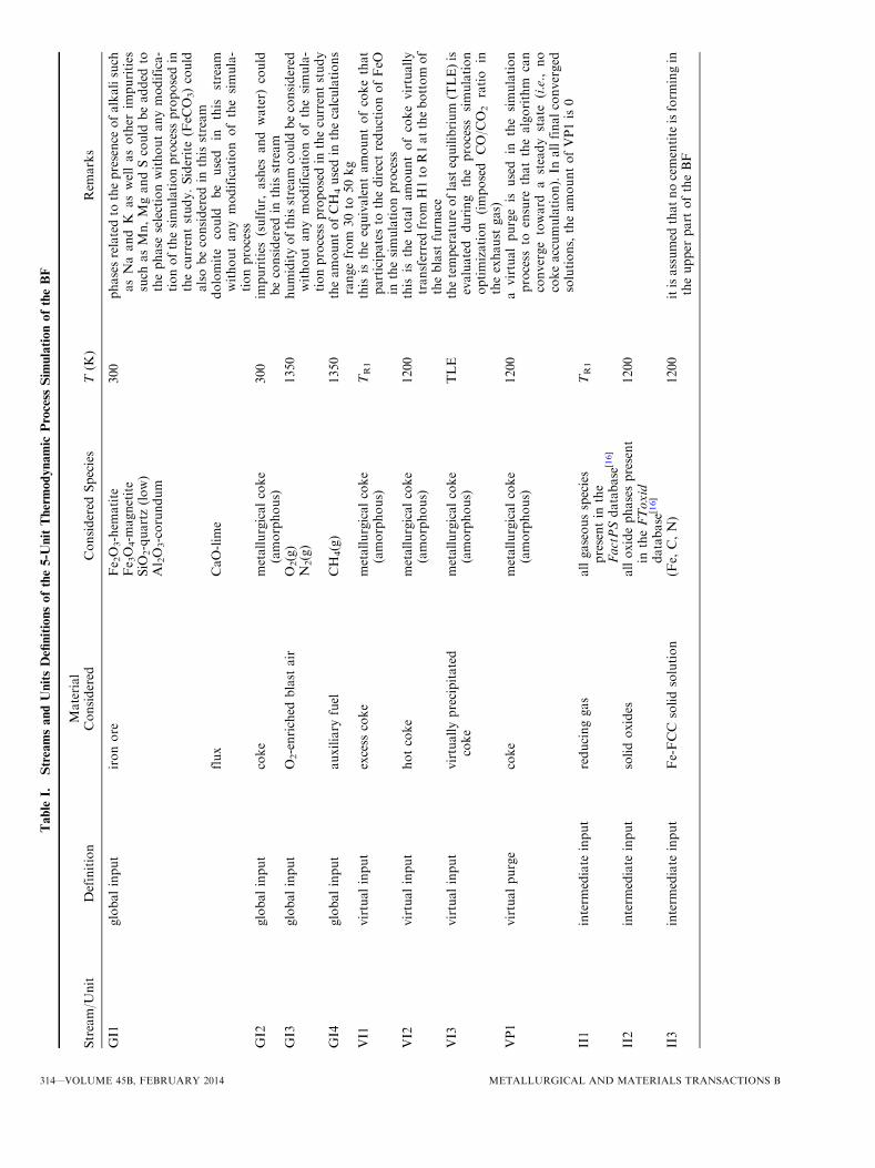
Table
I.StreamsandUnitsDefinitionsofthe5-U
nitThermodynamic
Process
Sim
ulationoftheBF
Stream/U
nit
Definition
Material
Considered
Considered
Species
T(K
)Rem
arks
GI1
globalinput
ironore
Fe 2O
3-hem
atite
300
phasesrelatedto
thepresence
ofalkalisuch
asNaandK
aswellasother
impurities
such
asMn,MgandScould
beadded
tothephase
selectionwithoutanymodifica-
tionofthesimulationprocess
proposedin
thecurrentstudy.Siderite(FeC
O3)could
alsobeconsidered
inthisstream
Fe 3O
4-m
agnetite
SiO
2-quartz(low)
Al 2O
3-corundum
flux
CaO-lim
edolomite
could
be
used
inthis
stream
withoutanymodification
ofthesimula-
tionprocess
GI2
globalinput
coke
metallurgicalcoke
(amorphous)
300
impurities
(sulfur,
ashes
and
water)
could
beconsidered
inthisstream
GI3
globalinput
O2-enriched
blast
air
O2(g)
1350
humidityofthisstream
could
beconsidered
withoutanymodification
ofthesimula-
tionprocess
proposedin
thecurrentstudy
N2(g)
GI4
globalinput
auxiliary
fuel
CH
4(g)
1350
theamountofCH
4usedin
thecalculations
rangefrom
30to
50kg
VI1
virtualinput
excess
coke
metallurgicalcoke
(amorphous)
TR1
this
istheequivalentamountofcokethat
participatesto
thedirectreductionofFeO
inthesimulationprocess
VI2
virtualinput
hotcoke
metallurgicalcoke
(amorphous)
1200
this
isthetotalamountofcokevirtually
transferredfrom
H1to
R1atthebottom
of
theblast
furnace
VI3
virtualinput
virtuallyprecipitated
coke
metallurgicalcoke
(amorphous)
TLE
thetemperature
oflastequilibrium
(TLE)is
evaluated
during
the
process
simulation
optimization
(imposed
CO/C
O2ratio
intheexhaust
gas)
VP1
virtualpurge
coke
metallurgicalcoke
(amorphous)
1200
avirtualpurgeis
used
inthesimulation
process
toensure
thatthealgorithm
can
convergetoward
asteady
state
(i.e.,
no
cokeaccumulation).In
allfinalconverged
solutions,theamountofVP1is0
II1
interm
ediate
input
reducinggas
allgaseousspecies
presentin
the
FactPSdatabase
[16]
TR1
II2
interm
ediate
input
solidoxides
alloxidephasespresent
intheFToxid
database
[16]
1200
II3
interm
ediate
input
Fe-FCC
solidsolution
(Fe,
C,N)
1200
itisassumed
thatnocementite
isform
ingin
theupper
part
oftheBF
314—VOLUME 45B, FEBRUARY 2014 METALLURGICAL AND MATERIALS TRANSACTIONS B

Table
I.continued
Stream/U
nit
Definition
Material
Considered
Considered
Species
T(K
)Rem
arks
II4
interm
ediate
input
hotexhaust
gas
allgaseousspecies
presentin
theFactPS
database
[16]
1200
II5
interm
ediate
input
partially
cooled
exhaust
gas
allgaseousspecies
presentin
theFactPS
database
[16]
TLE
GO1
globaloutput
slag
SiO
2TR1
other
solidphasescanform
/precipi-
tate
intheLPoftheblast
furnace
iftheprocess
parametersare
notopti-
mal.In
this
case,thesesolidphase
impurities
would
bepresentin
this
stream
CaO
Al 2O
3
FeO
Fe 2O
3
GO2
globaloutput
pig
iron
(Fe,
C,Si,N,Al)
TR1
GO3
globaloutput
cooledexhaust
gas
allgaseousspecies
presentin
theFactPS
database
[16]
420
R1
equilibrium
reactor
allpotentiallystable
phases*
TR1
adiabaticreactor
QR1¼
DH
R1¼
0ð
Þthatreaches
thetarget
tappingtem-
perature
(TR1)
*Ca2SiO
4is
considered
tobemeta-
stable
R2
equilibrium
reactor
allpotentiallystable
phases*
1200
isothermalreactor(T
=1200K)
*cementite
isconsidered
tobemeta-
stable
R3
virtualequilibrium
reactor
allpotentiallystable
phases
TLE
equilibrium
cooling
with
precipita-
tionofCallowed
tothetemperature
oflast
equilibrium
(TLE)
RSF3
virtualequilibrium
reactor
420
sootform
ation
(Cprecipitation)is
supposednotto
occurin
thisreactor
H1
virtualheatingreactor
coke
300
fi1200
impurities
(sulfur,
ashes
and
water)
could
beconsidered
inthisstream
C1
virtualnonequilibrium
coolingreactor
cooledexhaust
gas
allgaseousspecies
presentin
theFactPS
database
[16]
TLE
fi420
thecomposition
ofthegasphase
issupposedto
beconstantandnosolid
phase
precipitationisallowed
Allinputandoutputstream
amounts
are
defined
onaone-metric-ton-liquid–iron-productionbasisandare
atatm
osphericpressure
(operatingpressure
ofeach
reactor)
unless
specified
inthetext.
METALLURGICAL AND MATERIALS TRANSACTIONS B VOLUME 45B, FEBRUARY 2014—315

values from one BF to another since kinetic factors andin-house data are taken into account upon their oper-ation. Unless specified in subsequent sections, theseconditions are used to generate all the results presentedin Section IV. The chemical composition of each ironore studied in the current study is given in Table II andhas been no.ed (numbered) for subsequent identificationin the text.
At the end of the simulation, the implementedprocedure provides a set of optimized parameters anda list of all the phases and their respective amounts thatexit the BF. This set of input and output data completelysatisfies all the constraints related to mass and heatbalances as well the other specific BF constraintsdetailed in Section III–B–4. Key assumptions consid-ered in the establishment of the proposed simulationstrategy of the BF are summarized as follows:
� No unreduced FeO enters R1. Therefore, no reduc-tion of this FeO by the submerged coke column in thelower zone is considered.� The equilibrium reactor R2 considers manifestations
of both indirect and direct reduction of wustite.� No pulverized coal injection in the bottom of the BF
is considered in this specific example.� No coke impurities such as ashes and volatiles are
considered in the feedstock of this specific example.� Carbon saturation of the liquid pig iron is imposed by
its equilibrium with amorphous carbon (metallurgicalcoke), not graphite.� No dust particle(s) are exiting the BF.� The target CO/CO2 ratio of the cooled exhaust gas is
assumed to be 1.045.� The slag phase is only produced in the bottom part of
the BF (in R1).� Cementite is considered as a metastable phase in the
upper part of the BF.� A target tapping temperature TR1 of 1800 K
(1527 �C) is used throughout the current study.
1. Thermodynamic simulation of the lower partof the BF
In the lower part of the BF, heat is generated by thecombustion of incandescent coke (VI2) with hot O2-enriched air (GI3) to melt the solid iron (stream II3) andthe solid oxides (stream II2). It also provides heat for theendothermic direct reduction by coke of FeO and some
oxide impurities such as SiO2 and MnO. It is modeledusing a simple unit reactor (unit R1 in Figure 4)operating under adiabatic conditions. The overall chem-ical reaction at the origin of this heat generation isexpressed as follows:
C cokeð Þ þ 1=2O2 gð Þ ! CO gð Þ; Dh0 1800 K (1527 �CÞ½ �¼ �132:5 kJmol�1 ½8�
In addition to coke which is introduced at the top ofthe BF (GI2) and virtually heated in a special heatexchanger (H1) before reacting in the lower part of theblast furnace, a stream of preheated natural gas (GI4) isalso used at the tuyere level. This reduces the amount ofcoke needed in the burden. In the current study, the flowof natural gas is set to a value ranging from 30 to 50 kg/(metric ton) of liquid iron as suggested by Peacey andDavenport.[13] The target temperature of this adiabaticreactor is 1800 K (1527 �C), i.e., the tapping tempera-ture, a temperature at which the slag (GO1) and theliquid pig iron (GO2) are assumed to be in equilibrium.This target temperature is obtained by optimizing theflow and the composition of the hot O2-enriched airinput stream (GI3) using MADS. Heat produced by thisreactor will be carried out to the upper part of the BFvia the hot reducing gas (II1) and the hot virtual cokeinput stream (VI1).
2. Thermodynamic simulation of the higher partof the BFAs presented previously, the BF is modeled in the
current study using a 5-unit flow sheet, i.e., threeequilibrium reactors, one heat exchanger used to quenchthe exhaust gas and one heat exchanger to heat the coldcoke (Figure 4). The higher part of the BF is modeled byfour of these thermodynamic units. The first unitsimulating the higher part of the BF is an isothermalreactor (R2) operating at a constant temperature of1200 K (927 �C). In this reactor, it is supposed that allthe iron from the iron ore (oxide impurities are alsoconsidered in this charge) coming from the top of the BF(stream GI1) and flowing down to the tuyere iscompletely reduced to metallic iron. This temperatureis considered to be the thermal reserve zone temperatureand defines the largest isotherm of the BF.[35] As it canbe seen in Figure 4, the gas stream coming from the
Table II. Iron Ore Chemical Compositions Used in the BF Simulation Defined on a One-Metric-Ton-Liquid–Iron-Production
Basis
Iron Ore ID
Wt pct
Total Iron Ore Amount (kg) CaO Flux Amount (kg)Fe2O3 Fe3O4 SiO2 Al2O3 CaO
1 89.9 0 6.3 3.8 0 1589.7 1502 94.7 0 3.3 2.0 0 1509.7 753 34.9 56.8 7.4 0.9 0 1526.7 1504 91.4 1.6 2.5 0.4 4.1 1536.1 0*
* Self-fluxed iron ore.
316—VOLUME 45B, FEBRUARY 2014 METALLURGICAL AND MATERIALS TRANSACTIONS B

bottom of the BF and produced by the combustion ofcoke with O2-enriched air at high temperature in frontof the tuyere enters this reactor at 1800 K (1527 �C).This combustion gas will provide (1) heat for the directreduction of FeO:
FeO sð Þ þ C cokeð Þ ! Fe sð Þ þ CO gð Þ;Dh0 1200K (927 �C)½ � ¼ 137:9 kJmol�1
½9�
and (2) the reducing agent, i.e., CO(g), that will reduceindirectly about 70 pct of the total amount of FeO(Barnaba[36]):
FeO sð Þ þ CO gð Þ ! Fe sð Þ þ CO2 gð Þ ½10�
Excess carbon needed to complete the reductionprocess via Reaction [9] comes from the virtual streamVI1 exiting the bottom part of the BF at a temper-ature of 1800 K (1527 �C) as seen in Figure 4. Eventhough this excess coke flow stream is not physicallyobserved in the BF, its magnitude value providesinsight about the amount of carbon that ultimatelyparticipates in the direct reduction process describedby Eq. [9].
It is to be noted that direct reduction given by Eq. [9]is observed experimentally at temperatures greater than1200 K (927 �C), i.e., below the thermal reserve zone, asit is a strongly endothermic reaction. However, thisobservation did not influence the precision of our
simulations, as it is not intended to describe the exacttemperature profile inside the BF.The upper quarter of the shaft situated in the higher
part of the BF where the temperature of the exhaust gasdecreases rapidly because of transfer of heat to cold ironore, coke and fluxes is modeled using a second equilib-rium reactor (third unit defined as R3) and a final heat
Fig. 5—Schematic representation of the global optimization strategy to solve overall heat and mass balances of the BF.
500 520 540 560 580 600 620 640 660 680 7000
2
4
6
8
10
12
14
16
18
20
22
Max. coke value
CO
/CO
2 ra
tio (
vol.)
Coke optimal value (kg)
Min. coke value
Fig. 6—Evolution of the CO/CO2 ratio in GO3 as a function of thecoke consumption in the 4-unit process using iron ore #3 withnCH4
GI4 ¼ 30 kg.
METALLURGICAL AND MATERIALS TRANSACTIONS B VOLUME 45B, FEBRUARY 2014—317

exchanger (fourth-unit defined as C1). The equilibriumreactor is introduced in the simulation to adjust the finalequilibrium state reached by the exhaust gas. This unit(R3) is operated at a constant temperature (TLE)optimized by MADS to reproduce typical experimentalvalues of the CO/CO2 ratio observed in the cooled BFexhaust gas.[13] Results of preliminary tests using the4-unit process (Figure 4(a)) performed using a simula-tion strategy with a similar adjusting equilibrium reactorbut operating at the final cooled exhaust gas tempera-ture (for which soot formation is not allowed) revealthat the predicted vol pct of CO(g) in the final cooledexhaust gas is overestimated in comparison with typicalexperimental observations (Figure 5). The original sim-ulation strategy also evidently induces a more importantcarbon solution loss [high CO(g) concentration] thathad to be compensated by an unusually large optimizedcoke input amount as presented in Figure 6.
For these reasons, it was decided to explore thepossibility of performing equilibrium cooling of theexhaust gas to a temperature for which a CO/CO2 targetratio is reached followed by a fast cooling of the exhaustgas at constant composition (gas quenching) in a virtualheat exchanger. The equilibrium cooling reactor (R3)allows for the formation of soot in the form of cokewhich is virtually recycled into the isothermal reactor.This virtual recycling loop of coke (V13) induces theneed of a virtual purge stream of coke (VP1) to ensurethat the simulation process could reach a steady state,i.e., no coke accumulation in the system. During thesimulation process, the virtual purge stream amountautomatically tunes the amount of coke introduced inthe system (GI2) to avoid any coke excess (nil amount inthe VP1 stream at the converged solution) at the end ofthe simulation. Finally, the enthalpy needed to heat thecoke from room temperature to 1200 K (927 �C) iscalculated by the heat exchanger (H1).
The overall heat balance for this part of the systemcan be expressed as follows:
DHHP ¼ DHR2 þ DHR3 þ DHC1 þ DHH1 þ DHHL ½11�
At the thermal balance state, the total variation ofenthalpy in the higher part of the reactor DHHP is equalto 0. The enthalpy needed to heat coke DHH1 and tomaintain a constant temperature in these reactorsDHR2 þ DHR3ð Þ is provided by the hot exhaust gascooled by a counter-current heat exchange DHC1. In thecurrent study, it is assumed that there is no heat loss,i.e., DHHL ¼ 0:
3. Phase selection and thermodynamic databasesAll the phases (i.e., stoichiometric compound, liquid
and solid solutions, and the gas phase) considered in theequilibrium calculations needed to optimize inputstreams and other operating parameters of the BF arepresented in detail in the documentation of the FactSagesoftware (see FactPS and FToxid databases).[16] Thisdocumentation also includes thermodynamic assess-ments used to parameterize the Gibbs free energyfunctions. Unless specified in the text, graphite isconsidered as a metastable phase in all our calculations.
It is to be noted that some special phase selections areused in the current study for some equilibrium reactorspresented in Figure 4:
(1) Cementite (Fe3C) was assumed not to form in theisothermal reactor R2. As presented in Section III–B–4, an excess of carbon is present in this reactorwhich saturates the solid iron (in this case the Fe-FCCsolid solution) going to the lower part of the blastfurnace. Under these equilibrium conditions,cementite (not amorphous carbon) saturates iron andthus defines the maximum solubility of C in Fe.However, the thermodynamic activity AFe3C ofcementite, when it is considered as ametastable phasein the system, is relatively small (=2). The resultingthermodynamic chemical driving force for precipita-tion of cementite calculated as �RT ln AFe3Cð Þ istherefore also small, about �7 kJ mol�1 at 1200 K(927 �C). According to the nucleation theory, theresulting activation energy for nucleation of cement-ite will be high,[37] validating our assumption thatcementite does not form in this reactor.
(2) Dicalcium silicate (Ca2SiO4 or 2CaOÆSiO2) wasassumed not to form in the adiabatic reactor R1.Like cementite in the isothermal reactor, the activityof dicalcium silicate is small (=1.3) inducing a lowthermodynamic chemical driving force for precipi-tation of �3.9 kJ mol�1. Moreover, preliminaryresults using the proposed thermodynamic simula-tion process of the BF have shown that the totalamount of slag going out of the BF(output streamGO1) in Figure 4 is considerably underestimatedcompared with experimental evidence when thisphase is allowed to precipitate in the reactor.
(3) The chemical composition of the gas phase exitingthe virtual equilibrium cooling reactor R3 isassumed to be that of the final exhaust gas definedby the output stream GO3 in Figure 4. Thishypothesis implies that the gas is quenched from thetemperature TLE of this reactor to the exhausttemperature without the possibility of precipitatingany solid phase (e.g., no soot is allowed to form inthis region). From a heat-transfer perspective, it isagain a reasonable hypothesis as cold iron ore,fluxes, and coke will be heated rapidly by thecounter-current exhaust gas flow coming from thethermal reserve zone.
4. Global optimization strategy of the BF processA global optimization strategy was designed in the
current study based on the 5-unit thermodynamicprocess simulation to ensure that the overall mass andheat balances of the system are simultaneously respectedat the end of the simulation. A schematic representationof this strategy is presented in Figure 5. For a given ironore chemical composition and a fixed amount of flux(GI1) and auxiliary fuel (GI4) (which is in this casemethane), the simulation process starts (step #1) with afirst rough estimate of the amount of air (GI3) and coke(GI2) to be added to the system. The iterative processstarts with the MADS algorithm optimizing the amountof oxygen nO2
GI3 in the air input stream entering the
318—VOLUME 45B, FEBRUARY 2014 METALLURGICAL AND MATERIALS TRANSACTIONS B

adiabatic reactor at the bottom of the BF (R1) to satisfythe target tapping temperature TR1 of 1800 K (1527 �C)(step #2). The following optimization problem is solvedby MADS:
minnO2GI32<n
TR1 nO2
GI3
� �� 1800
� �2½12�
For the first iteration, the amount of stream II2 has tobe estimated and is supposed to consist of the pureoxides CaO, MgO, SiO2, Al2O3 present in the studiediron ore. The intermediate input stream of solid iron II3going into the R1 reactor also has to be estimated and isdefined as a pure stream containing 1000 kg (calculationbasis) of Fe-FCC. It is assumed in this case that all theFe-containing minerals are reduced in the isothermalreactor R2. After this first optimization of the R1reactor, global output streams GO1 and GO2 as well asthe virtual coke input (VI1) and the reducing gas (II1)streams entering the isothermal reactor R2 which modelthe thermal reserve zone are evaluated.
The third step involves the evaluation of the equilib-rium state of reactor R2. A binary decision is taken afterthis equilibrium calculation: if no FeO remains in II2,then the simulation is continued forward (step #5);otherwise MADS is used to find a better estimate of thecoke amount GI2. In this case, MADS will try tominimize the amount of coke DnCGI2 to be added to GI2to completely reduce FeO nFeOII2 in stream II2 (step #4):
minDnC
GI22<n
DnCGI2
subject to
nFeOII2 ¼ 0
½13�
When this requirement is met, the simulation contin-ues with the optimization of the higher part of the BFmodeled by the isothermal reactor R3. As mentionedpreviously, the temperature of this reactor where theexhaust gas is cooled with the possibility of precipitationof coke is an optimized variable. Again, MADS isinvoked to find the exact temperature at which the targetCO/CO2 ratio of 1.045 in stream II5 is obtained bysolving the following problem (step #5):
minTLE2<n
nCOII5 TLEð ÞnCO2
II5 TLEð Þ� 1:045
!2
½14�
Carbon precipitating in the form of amorphouscarbon from this equilibrium cooling reactor is recycled(stream VI3) to the R2 isothermal reactor while theexhaust gas of the II5 stream is quenched to 420 K(147 �C) using the cooling unit C1. As the higher part ofthe BF involves the presence of a recycling stream(stream VI3), an iterative loop has to be implemented toensure that the equilibrium temperature of the reactorTLE and the amount of precipitated and recycled cokehave reached a converged and stable value. In the courseof this iterative loop, an excess of coke in the higher part
of the BF rcan occur. This excess carbon coming fromreactor R2 will be dumped into the virtual purge VP1. Ifthis situation occurs, then the simulation process willadjust the incoming amount of coke in stream GI2 toensure that no coke excess in the overall process ispresent (step #6).If no excess carbon is present in stream VP1, the
overall heat balance of the higher part of the BF can beevaluated according to Eq. [11] (step #7). Input streamsGI3 and GI2 amounts will finally be adjusted dependingon this heat balance: if heat is required in this part of theBF, then the quantity of nitrogen nN2
GI3 in stream GI3 willbe increased by DnN2
GI3 according to the followingequation:
DnN2
GI3 ¼�DHHPR 420Kð147 �CÞ
1800Kð1527 �CÞ cP N2ð ÞdT� � ½15�
In Eq. [15], cP N2ð Þ represents the heat capacity (bymass) of N2 gas. According to Eq. [11], it is assumed inthe current study that heat is predominantly transportedin the system from the lower part to the upper part bythe gas phase via convection, and not by heat conduc-tion or thermal radiation. To heat this extra amount ofN2 in the lower part of the BF, a certain amount of cokeDnCGI2 should also be added to stream GI2 using theenthalpy released by the combustion of incandescentcoke in air. This quantity is evaluated as follows:
DnCGI2 ¼�DnN2
GI3 R 1800Kð1527 �CÞ1350Kð1077 �CÞ cP N2ð ÞdT
Dhcombustion þR 1200Kð927 �CÞ300Kð27 �CÞ cp cokeð ÞdT
½16�
with
C cokeð Þ1200Kð927 �CÞþ1=2O2 gð Þ1350 Kð1077 �CÞ
! CO gð Þ1800 Kð1527 �CÞ; Dhcombustion
½17�
In Eq. [16], Dhcombustion represents the variation ofenthalpy of combustion (by mass) defined by chemicalreaction [17]. According to Eq. [15] and Eq. [16], it isassumed that the excess amount of CO produced by thecombustion of coke to heat N2 in the lower part of theBF will not provide substantial heat to the higher part ofthe BF. This assumption does not alter the precision ofthe converged solution.In the opposite case, if heat is to be removed from the
upper part of the blast furnace, i.e., DHHP<0, then onlythe amount of N2 in stream GI3 is lowered according toEq. [15]. In this case, the amount of coke in the systemwill not be adjusted to ensure that the reducing powerability of the BF is not lowered. One of the mainobjectives of the simulation process is to evaluate theoptimal (in this case also the minimal) amount of coketo be used in the BF that allows for a complete reductionof the iron ore; a small decrease of the coke amountduring the iterative process could alter the convergencebehavior of the simulation toward this optimal state.This procedure is performed iteratively until bothoverall heat and mass balances are respected as well as
METALLURGICAL AND MATERIALS TRANSACTIONS B VOLUME 45B, FEBRUARY 2014—319

until all the input and output stream amounts haveconverged toward stable values.
IV. THERMODYNAMIC SIMULATIONRESULTS
A. Simulation Results for the 4-Unit Process(No Coke Recirculation)
The original simulation flow sheet of the BF ispresented in Figure 4(a) and is referred to as the 4-unitprocess. As mentioned previously, it is assumed in thissimulation process that the exhaust gas coming from thethermal reserve zone is cooled in equilibrium conditionsto the final exhaust gas temperature without thepossibility of forming soot. The influence of the firstestimate of the coke consumption in the BF on itsoptimal amount in the reactor is presented in Figure 6.According to this figure, the global optimization strat-egy proposed in the current study and applied to theoriginal 4-unit process does not automatically minimizethe amount of coke used in the BF unless a globaloptimization strategy managed by MADS to do so isused.
Therefore, an infinite no. of solutions exist betweenthe lowest amount of coke to be used to reducecompletely all the iron ore and the maximum amountof coke above which an excess of unreacted coke will bepresent in the BF. This implies that the simulationperformed with the original 4-unit approach is sensitiveto the initial guess: an unnecessary large amount of cokein the reactor does not therefore result in a coke excessin the BF, as it can be burnt by air and still solves theoverall mass and heat balances of the system. In thiscase, the CO/CO2 ratio of the exhaust gas is the perfectindication of the optimum selected input amounts, ahigh coke injection inducing a high CO/CO2 ratio in theexhaust gas. If compared with industrial CO/CO2 ratiosreported by Peacey and Davenport[13] for 4-BFs whichare between 1 and 1.4, the 4-unit process overestimatesthe CO/CO2 ratio even for the minimal amount of coketo be used to complete the reduction of the iron ore.These results motivated the construction of the 5-unitprocess which is used to generate all the other resultspresented in the current study.
B. Effect of the Carbon State on the Optimized Inputand Output Streams Variables
The parameterization of the Gibbs free energy func-tion of coke presented in Appendix 1 of the currentstudy was done to demonstrate the influence of theselected carbon state, i.e., graphite or metallurgical coke,on the BF optimized process parameters. The first effectof the carbon state on the thermodynamic simulations isrelated to the overall heat balance of the system. Thevariation of the enthalpy to perform the graphite-to-amorphous phase transition is 13.6 kJ mol�1 understandard conditions and goes up to 15.1 kJ mol�1 at1800 K (1527 �C). As a direct consequence, the com-bustion of graphite at the tuyere level in the BF is less
exothermic, representing about 89 pct of the valuepresented in Eq. [8]. As presented in Table III, thisobservation does not imply that more graphite is neededin the BF, as its minimal amount is set by the completereduction of the iron ore and the specific CO/CO2
requirements rather than by the heat balance. However,the amount of O2 in the blast is lower when coke is used(the combustion in this case is more exothermic) whichmeans that more FeO is directly reduced by coke thanfor graphite. Heat needed to perform the direct reduc-tion is provided by N2 as can be seen in Table III.The second effect of the carbon state on the simula-
tion results is related to the exhaust gas chemicalcomposition. As provided in Table III, the temperatureof last equilibrium (TLE) in unit R3 is 64 deg lowerwhen coke is used for reasons presented in Section IV–E.As a direct consequence, the chemical composition ofthe equilibrium exhaust gas coming out of unit R3 isalso dependent on the carbon state considered in the BF.This simulation parameter can be critical when predict-ing precisely greenhouse gas emissions such as CO2 andCH4 as highlighted by Table III.The last effect of the carbon state, on the thermody-
namic simulation results, is the modification of carbonsolubility in the liquid pig iron. Coke is less thermody-namically stable than graphite. Carbon saturation in theliquid pig iron is therefore higher when coke saturatesthe metallic liquid solution in comparison with graphite.
C. Effect of the Pig Iron/Slag/Coke EquilibriumTemperature on the Coke Consumption, the Presenceof Si in Liquid Fe and on the Slag Basicity
In this section, we present the effect of the finalequilibrium temperature in the LP of the BF reactor(tapping temperature) on the chemical composition ofliquid pig iron and on the slag basicity. Figure 7(a) showsthat the coke consumption increases almost linearly as thetemperature of theLPof theBF is increased. In this figure,
Table III. Optimized BF Process Parameters Comparison
Between Injected Coke and Graphite for the Reduction of Iron
Ore #1 with nCH4
GI4 ¼ 30 kg
BF Process Parameter Coke Graphite
Injected carbon amount GI2 (kg) 458 456Carbon in stream VI1 137 113
BlastN2 (kg) 1109 1071O2 (kg) 383 418
TLE of unit R3 (K) 849 913Exhaust gas composition (vol pct)N2 51.1 49.4CO 22.7 23.4CO2 21.7 22.4H2O 1.0 1.5H2 3.2 3.3CH4 0.3 293 ppm
Pig iron composition (wt pct)C 5.9 4.8Si 1.6 1.3Al 1272 ppm 1225 ppm
320—VOLUME 45B, FEBRUARY 2014 METALLURGICAL AND MATERIALS TRANSACTIONS B

theminimal LP temperature needed tomelt completely allthe oxide impurities is presented as a dashed line andoccurs at around 1770 K (1497 �C) for the iron oreconsidered in these calculations. As is well known,reduction of SiO2 is thermodynamically favored astemperature is increased, which explains the increases inthe equilibrium silicon content as a function of the LPtemperature presented in Figure 7(b). Finally, the evolu-tion of the basicity of the (bottom or hearth) slag definedin this case as theCaO/(SiO2+Al2O3) ratio (byweight) ispresented in Figure 7(c). To operate the BF for anoptimal slag basicity of around 1.2, the tapping temper-ature for the studied iron ore should be around 1790 K(1517 �C), which is close to the recommended generaltapping temperature.[13]
D. Effect of the Iron Ore Chemical Composition onOperating Parameters and Output Streams of the BF
In this section, several iron ore compositions havebeen tested in the 5-unit thermodynamic simulationprocess. Results of these simulations are presented inTable IV and can be compared with the reference dataprovided by Peacey and Davenport.[13] In this table,predicted values are presented in bold characters. It is tobe noted that Peacey and Davenport[13] did not providethe exact chemical composition of the iron ore consid-ered for their proposed reference data, which limits theevaluation of the precision of the thermodynamic sim-ulations performed in the current study. Apart from theamount of C in the liquid pig iron, which is slightlyoverestimated when compared with reference data, thereis excellent agreement between predicted and referencedata. In our simulations, the amount of carbon in theliquid pig iron is imposed by coke saturation of the melt.To obtain a saturation of about 5 pct, graphite wouldhave to be considered in the calculations. Anotherthermodynamic justification that could explain this smalldiscrepancy is the extrapolation of the Gibbs free energyfunction of coke parameterized in the current study tohigh temperatures where no experimental data arereported in the literature. In this case, the thermody-namic stability of coke, compared with graphite, wouldbe underestimated. It also appears that the predicted Sicontent in the resulting pig iron in complete equilibriumwith the slag phase is slightly overestimated whencompared with other conventional BF data.[38] This ispresumably caused by kinetics limitations of the reduc-tion of SiO2 in the LP of the BF.[38] In such a perspective,models of reaction rates should be added to our model ofthe BF in future refinements of our proposed approach.
E. Influence of the Selected Carbon Gibbs Free EnergyFunction and Nitrogen Partial Pressure on the BoudouardReaction Equilibrium at Low Temperature on the PhaseEquilibria of the BF
Figure 8 presents the [log10(PO2) vs T] predominancephase diagram of the Fe-O system obtained from
1650 1700 1750 1800 1850 1900 1950 2000
420
440
460
480
500
520
Cok
e op
timal
val
ue (
kg)
Tapping temperature (K)
completely melted oxides
(a)
(b)
(c)
1650 1700 1750 1800 1850 1900 1950 20000.6
0.8
1.0
1.2
1.4
1.6
1.8
2.0
2.2
2.4
2.6
2.8
Si w
t. %
Tapping temperature (K)
1650 1700 1750 1800 1850 1900 1950 20001.1
1.2
1.3
1.4
1.5
1.6
1.7
Bas
icity
(C
aO/(
SiO
2+A
l 2O3)
) (w
t.)
Tapping temperature (K)
Fig. 7—Evolution of (a) coke optimal value, (b) Si (wt pct) dissolvedin the liquid pig iron, (c) resulting slag basicity as a function of thetapping temperature when reducing iron ore id #1 using metallurgi-cal coke and with nCH4
GI4 ¼ 30 kg.
METALLURGICAL AND MATERIALS TRANSACTIONS B VOLUME 45B, FEBRUARY 2014—321

Table IV. BF Input/Output Parameters for Different Iron Ore Using Coke Compared with Reference Data of Peacey and Daven-
port[13] (Calculation Basis: 1000 kg of Liquid Fe)
BF Parameters Unit Iron Ore #1 Iron Ore #2 Iron Ore #3 Iron Ore #4 Ref. [13]
Iron ore total amount(flux and impurities included)
kg 1740 1585 1677 1536 1750*
Coke input amount kg 442 427 421 417 450
Blast temperature K 1350 1350 1350 1350 1350Blast pressure bar 2 2 2 2 2 to 3.4N2 in blast kg 1020 1100 923 1161 1027
vol pct (STP) 75.5 78.3 74.2 80 78.9
O2 in blast kg 378 348 366 330 313vol pct (STP) 25.5 21.7 25.8 20 21.1
Tapping T K 1800 1800 1800 1800 1800CaO/(SiO2 + Al2O3) ratio in the slag – 1.1 1.2 1.5 1.7 1.1 to 1.2
Slag total amount kg 286 139 247 100 300Auxiliary CH4 kg 50 50 50 50 50Top-gas temperature K 420 420 420 420 420Top-gas pressure bar 1 1 1 1 0.3 to 2.2Top-gas amount kg 2264 2294 2109 2320 2300Top-gas analysis
pct N2 vol pct 48 51 47 53 49
pct CO vol pct 23 21 23 21 23pct CO2 vol pct 22 20 22 20 22
pct H2 vol pct 5 5 5 5 3
pct H2O vol pct 2 2 2 1 3
pct CH4 vol pct 0 1 1 1 –Pig iron chemical compo.
C wt pct 6.2 6.4 6.1 6.6 4 to 5
Si wt pct 1.0 0.6 1.3 0.3 0.3 to 1
* Total amount of iron ore (1600 kg) and CaO flux (150 kg).
Fe2O3
Fe3O4
FeO
Slag
Fe(BCC)Fe-Liq.
Fe(FCC)Fe(BCC)
Graphite
Coke
(Coke, PN2=0.5)
T(o
pti
miz
ed)=
849K
T(K)
log 1
0 p
(O2)
/atm
800 900 1000 1100 1200 1300 1400 1500 1600 1700 1800 1900 2000-30
-25
-20
-15
-10
-5
0
Fig. 8—(PO2 vs T) predominance phase diagram of the Fe-O system. The calculations are based on a total pressure of 1 atm.
322—VOLUME 45B, FEBRUARY 2014 METALLURGICAL AND MATERIALS TRANSACTIONS B

thermodynamic calculations performed with FactSagebased on a total pressure of 1 atm. The dashed linesrepresent the equilibrium partial pressure of O2 imposedby the Boudouard reaction (Eq. [2]) in a system havingan excess of carbon.
As is well established, complete reduction of Fe2O3 toform metallic iron is thermodynamically favored attemperatures greater than 970 K (697 �C) when theBoudouard reaction constrains the reducing conditionsin the system and if the Gibbs free energy function ofgraphite is considered. For metallurgical coke, which isless thermodynamically stable than graphite, the mini-mum theoretical temperature needed to obtain metalliciron is 890 K (617 �C). Finally, if a nitrogen partialpressure is imposed on the system, as in conventionalBFs blowing enriched air (in this case PN2 = 0.5 in theupper part of the BF), the minimum temperature forcomplete reduction to metallic iron decreases to 855 K(582 �C). This temperature is close to the optimizedtemperature obtained from our simulations if anassumed CO/CO2 of 1.045 is to be reached before theexhaust gas is quenched. Moreover, if one assumes thatthe last equilibrium to be reached in the BF before theexhaust gas leaves the BF ris:
FeO sð Þ þ Fe3O4 sð Þ þ Cokeþ exhaust gas ½18�
then the required temperature for this equilibrium phaseassemblage would be exactly the optimized temperatureof the exhaust gas calculated from our simulations. TheGibbs phase rule defining the no. of degree of freedom Fas a function of the no. of distinct chemical species Cand no. of stable phases at equilibrium P, i.e.,F ¼ C� Pþ 2, confirms this observation. For the basicBF chemical system defined by N, C, Fe, O (C = 4), thephase assemblage provided in Eq. [18] with P = 4 iscompletely defined (F = 0) if the total pressure and thenitrogen activity in the system are imposed in the BF. Atthis temperature, the resulting CO/CO2 ratio determinedby this phase assemblage is equal to 1.045.
V. CONCLUSIONS AND PERSPECTIVES
In the current study, the conventional BF has beenmodeled using a 5-unit simulation flow sheet usingclassical thermodynamic calculations combined with adirect search algorithm called MADS. The complexityrelated to the formation and chemical evolution of theslag phase has demonstrated the necessity of simplifyingthis complex industrial process to a 5-unit counter-current reactor. To improve the thermodynamic descrip-tion of this system, the Gibbs free energy of metallur-gical coke has been parameterized and validated usingavailable experimental data. Several results obtainedwith this proposed simulation strategy were comparedwith the literature data and have demonstrated itsaccuracy and high predictive power.
This newly elaborated thermodynamic approach forsimulating BF can now be applied to study quantita-tively other important phenomena occurring in the BF,such as the accumulation of alkali elements and Zn and
subsequent degradation of the BF refractory materi-als.[39] Another example is liquid metal quality controlwhen sulfur is present.[40] In future study, this simulationstrategy will also be used to explore new optimaloperating conditions of the BF to meet new importantindustrial constraints such as reduction of gaseousemissions and improved energy efficiency of the process.Finally, the MADS algorithm will be used to performcomplex optimizations that simultaneously target liqui-dus temperature and slag viscosity to improve theoperation of the BF.
ACKNOWLEDGMENT
We would like to thank Professor Patrice Chartrandand Dr. James Sangster for their constructive criti-cisms of the current study.
APPENDIX 1
There are two specific amorphous forms of carbon:the diamond-like amorphous carbon and the graphite-like amorphous carbon.[41] The diamond-like amor-phous carbon is made of distorted sp3 bonds whereasthe graphite-like amorphous carbon is characterized bya high percentage (>80 pct) of sp2 bonds. The ratio offourfold diamond-like bonds to threefold graphite-likebonds (sp3/sp2) determines the structure.In fact in amorphous carbon the chemical bonds
among atoms are a mixture of sp2 and sp3 hybridizedbonds with a high concentration of dangling bonds.Because amorphous carbon is thermodynamically in ametastable state and the ratio of sp2 and sp3 hybridizedbonds are variable, physical properties of amorphouscarbon vary greatly depending on formation methodsand conditions. In the current study, we do not take intoaccount the specificity of the nature of the bindingwithin the solid in the formulation of the Gibbs freeenergy. We assume that coke is energetically defined bythe Gibbs free energy of an amorphous carbon withpurely covalent binding.The Gibbs free energy difference due to amorphiza-
tion of graphite can be written as follows:
Dgg:!a: Tð Þ ¼ Dhg:!a: T0ð Þ þZT
T0
Dcg:!a:P T0ð ÞdT0
�TDsg:!a: T0ð Þ � T
ZT
T0
Dcg:!a:P T0ð ÞT0 dT0
½A1�
with T0 = 298 K (25 �C), Dhg:!a:; Dsg:!a: and Dcg:!a:P
are, respectively, the molar enthalpy, molar entropy andmolar heat capacity change due to amorphization ofgraphite. In this assessment, Dsg:!a: T0ð Þ is taken to be0.2 R which is the upper theoretical limit value of theexcess ideal configurational entropy due to lattice disor-der in the amorphous phase determined by Spaepen[42]
METALLURGICAL AND MATERIALS TRANSACTIONS B VOLUME 45B, FEBRUARY 2014—323

and based on random network models. The Dcg:!a:p
expression used in the current study is set to a constantvalue (no temperature dependence) of similar ampli-tude as for silicon (0.96 J mol�1 K�1) and germanium(0.62 J mol�1 K�1) at room temperature evaluatedby Donovan et al.,[43] i.e., assuming Dcg:!a:
P ¼1 Jmol�1 K�1.
The standard molar enthalpy of amorphization ofgraphite Dhg:!a: [298 K (25 �C)] can be estimated usingthe following thermodynamic path:
graphite !298Kð25 �CÞ; Dhg:!L ½298Kð25 �CÞ�liquid
Dh1 # Dh2 "graphite !Tm; Dhg:!L Tmð Þ
liquid
½A2�
+
liquid !298Kð25 �CÞ; DhL!a: ½298K ð25 �CÞ;�amorphous
Dh3 # Dh4 "
liquid !Tg; DhL!a: Tgð Þ
amorphous
½A3�
Dhg:!a:½298K ð25 �C)] ¼ Dhg:!L½298K ð25 �C)]þ DhL!a:½298K ð25 �C)] ¼ Dh1 þ Dhg:!L Tmð Þþ Dh2 þ Dh3 þ DhL!a: Tg
� �þ Dh4
½A4�
with:
Dh1 ¼ZTm
½298K ð25 �CÞ�
cP graphiteð ÞdT ½A5�
Dh2 ¼Z½298K ð25 �CÞ�
Tm
cP liquidð ÞdT ½A6�
Dh3 ¼ZTg
½298K ð25 �CÞ�
cP liquidð ÞdT ½A7�
Dh4 ¼Z½298K ð25 �CÞ�
Tg
cP amorphousð ÞdT ½A8�
At Tg, the Clausius–Clapeyron rule can be applied:
DhL!a: Tg
� �¼ Tg DsL!a: Tg
� �½A9�
or equivalently:
DhL!a: Tg
� �¼ Tg DsL!g: Tg
� �þ Dsg:!a: Tg
� �� ½A10�
One can assume that
DsL!g: Tg
� �¼ DsL!g: Tmð Þ ½A11�
At the melting temperature Tm of graphite, theClausius–Clapeyron rule can be applied again:
DsL!g: Tmð Þ ¼ DhL!g: Tmð ÞTm
¼ �Dhg:!L Tmð ÞTm
½A12�
The value of Dsg:!a: Tg
� �in Eq. [A10] can be evaluated
from the theoretical molar excess configurational en-tropy of 0.2R determined by Spaesen[42] and using theDcg:!a:
p expression defined previously. This results in thefollowing equation:
Dsg:!a: Tg
� �¼ 0:2Rþ
ZTg
298 Kð25 �CÞ
Dcg:!a:P
TdT ½A13�
According to the Kauzmann–Beaman rule, a linearrelationship exists between Tm and Tg, i.e., Tg ¼ xTm
with x = 0.74 to 0.76 for purely covalent-type bond-ing.[44] Finally Eq. [A4] can be re-written using theprevious equations as follows:
Dhg:!a:½298 K (25 �C)� ¼ZTm
298 Kð25 �CÞ
cP graphiteð ÞdT
þZxTm
Tm
cP liquidð ÞdTþZ298 Kð25 �CÞ
xTm
cP amorphousð ÞdT
þ Dhg:!L Tmð Þ þ xTm
�Dhg:!L Tmð ÞTm
þ 0:2RþZxTm
298 Kð25 �CÞ
Dcg:!a:P
TdT
264
375
½A14�
According to Eq. [A14], three thermodynamic prop-erties associated to the liquid phase are required toestimate Dhg:!a: ½298K (25 �C)�. These properties areTm, Dhg:!L Tmð Þ, and cp(liquid).Thermodynamic data for liquid carbon[45] are scat-
tered due its metastability at standard pressure (i.e.,105 Pa). In fact graphite sublimates at 3915 K(3642 �C) under standard pressure. According to theliterature review of Savvatimskiy,[45] the melting tem-perature of graphite lies between 4000 K and 5000 K(3727 �C and 4727 �C). The recommended meltingtemperature proposed by Dinsdale[46] as well as therecent assessed value of Savvatimskiy[45] is 4800 K(4527 �C), with an estimated error of 100 deg accord-ing to the latter author. This temperature is inagreement with the most recent investigation of Kerleyand Chhabildas,[47] which states that the meltingtemperature of graphite is above 4600 K (4327 �C).In the current study, we have considered Tm = 4800 K(4527 �C).The molar heat of fusion of graphite Dhg:!L Tmð Þ is
more difficult to assess. Based on the optimization of the
324—VOLUME 45B, FEBRUARY 2014 METALLURGICAL AND MATERIALS TRANSACTIONS B

unary (P–T) phase diagram of the carbon, Bundy[48]
recommended a value of 105 kJ mol�1. This value is inagreement with the range recommended by Pottlacheret al.[49] (96 to 108 kJ mol�1). The latest assessment ofSavvatimskiy[45] suggests a value of 120 kJ mol�1. In thecurrent study, we considered an average value of110 kJ mol�1.
According to the literature review of Savvatimsky,[45]
the molar heat capacity of liquid cp(liquid) carbonranges between 38.4 and 49.2 J mol�1 K�1. A value ofcp(liquid) = 49.2 J mol�1 K�1 was used in the currentstudy as suggested by Savvatimsky.[45]
Using all these thermodynamic properties, a value ofDhg:!a: 298 K (25 �C)½ � ¼ 13:6 2:5 kJmol�1 is esti-mated which is exactly within the range of experimentallyreported values.[25] This estimated molar enthalpy ofamorphization of graphite also compares well with theexperimental data for amorphous silicon 11.9 kJmol�1[50] and amorphous germanium 11.6 kJ mol�1.[43]
It also agrees with the estimation made by de Bokxet al.,[51] i.e., that Dhg:!a: 298 K (25 �C)½ � should notexceed 15 kJ mol�1. A slightly higher value ofDhg:!a: 298 K (25 �C)½ � ¼ 19:2kJmol�1 attributed to thestrong bonding nature of carbon has been reported byKonno and Sinclair.[52] This value however contradictsthe constraint of de Bokx et al.[51] Moreover, this valuewas obtained experimentally byDSC on aC/Co thin film,where size and chemical effects between Co and C affectthe estimation.
The final theoretical Gibbs free energy functionpredicted from this procedure is compared with theexperimental data reported by Jacob and Seethar-aman[25] in Figure 1.
APPENDIX 2
See Figures A1, A2, A3 and A4.
Slag
Slag + SiO2(s4)
Slag + SiO2(s2)
Na6Si8O19
Na2SiO3
Na6Si2O7
Na2O(s2) + Na 4SiO4
Slag + Na2O(s2)
ASlag-liq + Na2O(s3)
Na4SiO4
Na2Si2O5
Slag + SiO2(s6)
1066K
SiO2/(Na2O+SiO2) (wt./wt.)
T(K
)
0.0 0.1 0.2 0.3 0.4 0.5 0.6 0.7 0.8 0.9 1.01000
1100
1200
1300
1400
1500
1600
1700
1800
1900
2000
Fig. A1—Pseudo-binary phase diagram of the Na2O-SiO2 system (nogas phase considered) calculated by FactSage using the FToxid data-base.[16]
Slag + Fe(liq) Slag + Fe(liq) + SiO2(s6)
Slag + Fe(BCC) + SiO2(s6)
Slag + Fe(BCC) + SiO2(s4)
Slag + Fe(FCC) + SiO2Slag + Fe(FCC)
Slag + Fe(BCC)
Slag + FeO
FeO + Fe(FCC) + Fe2SiO4
Fe(FCC) + SiO2(s4) + Fe2SiO4
1459KFe(FCC)+
Slag + Fe(FCC) + Fe2SiO4
Slag + Fe(FCC) + Fe2SiO4
1461K
SiO2/(FeO+SiO2) (wt./wt.)
T(K
)
0.0 0.1 0.2 0.3 0.4 0.5 0.6 0.7 0.8 0.9 1.01200
1300
1400
1500
1600
1700
1800
1900
Fig. A2—Pseudo-binary phase diagram of the FeO-SiO2 system(activity of Fe-FCC/-BCC/-liq. = 1) calculated by FactSage usingthe FToxid database.[16]
Slag
Slag + SiO2(s6)
Slag#1+ Slag#2
CaSiO3(s2) + SiO2(s4)
CaSiO3(s) + SiO2(s4)
CaSiO3(s) + SiO2(s2)
CaO + Ca2SiO4(s2)
CaO + Ca2SiO4(s)
Ca 3
Si 2O
7
Ca 3
SiO
5
CaO(s) + Ca2SiO4(s3)
ASlag-liq + CaO(s)
Ca 2
SiO
4(s2
)C
a 2S
iO4(
s3)
1710K1737K
CaS
iO3
SiO2/(CaO+SiO2) (wt./wt.)
T(K
)
0.0 0.1 0.2 0.3 0.4 0.5 0.6 0.7 0.8 0.9 1.01000
1200
1400
1600
1800
2000
2200
2400
Fig. A3—Pseudo-binary phase diagram of the CaO-SiO2 system cal-culated by FactSage using the FToxid database.[16]
METALLURGICAL AND MATERIALS TRANSACTIONS B VOLUME 45B, FEBRUARY 2014—325

REFERENCES1. A. Ghosh and S.K. Majumdar: Int. J. Adv. Manuf. Technol., 2011,
vol. 52, pp. 989–1003.2. S. Ueda, S. Natsui, H. Nogami, J.-I. Yagi, and T. Ariyama: ISIJ
Int., 2010, vol. 50, pp. 914–23.3. X.F. Dong, A.B. Yu, S.J. Chew, and P. Zulli: Metall. Mater.
Trans. B, 2010, vol. 41B, pp. 330–49.4. H. Nogami, M. Chu, and J.-I. Yagi: Comput. Chem. Eng., 2005,
vol. 29, pp. 2438–48.5. C. Gao, L. Jian, and S. Luo: IEEE Trans. Ind. Electron., 2012,
vol. 59, pp. 1134–45.6. L. Jian and C. Gao: IEEE Trans. Ind. Electron., 2012, pp. 1–1.7. F.A. Garcia, P. Campoy, J. Mochon, I. Ruiz-Bustinza, L.F.
Verdeja, and R.M. Duarte: ISIJ Int., 2010, vol. 50, pp. 730–37.8. X. Hao, F. Shen, G. Du, Y. Shen, and Z. Xie: Steel Res. Int., 2005,
vol. 76, pp. 694–99.9. D. Qiu, D.-J. Zhang, W. You, N.-N. Zhang, and H. Li: in Inter-
national Conference on Apperceiving Computing and IntelligenceAnalysis, 2009 (ICACIA 2009), 2009, pp. 61–64.
10. H. Saxen and F. Pettersson: in IEEE Symposium on ComputationalIntelligence and Data Mining, 2007 (CIDM 2007), 2007, pp. 368–75.
11. F. Pettersson, N. Chakraborti, and H. Saxen: Appl. Soft Comput.,2007, vol. 7, pp. 387–97.
12. F. Pettersson, H. Saxen, and K. Deb: Mater. Manuf. Process.,2009, vol. 24, pp. 343–49.
13. J.G. Peacey and W.G. Davenport: The Iron Blast Furnace, Theoryand Practice, 1st ed., Pergamon Press, Oxford, 1979, pp. 1–251.
14. E. Jak and P. Hayes: High Temp. Mater. Process. (Lond.), 2012,vol. 31, pp. 657–65.
15. V.I. Kulinich: Steel Transl., 2007, vol. 37, pp. 356–61.16. C.W. Bale, E. Belisle, P. Chartrand, S.A. Decterov, G. Eriksson,
K. Hack, I.H. Jung, Y.B. Kang, J. Melancon, A.D. Pelton, C.Robelin, and S. Petersen: CALPHAD, 2009, vol. 33, pp. 295–311.
17. G. Eriksson: Acta Chem. Scand., 1971, vol. 25, pp. 2651–58.18. G. Eriksson: Chem. Scr., 1975, vol. 8, pp. 100–103.19. S. Petersen, K. Hack, P. Monheim, and U. Pickartz: Int. J. Mater.
Res., 2007, vol. 98, pp. 946–53.20. W.T. Lankford, Jr.: The Making, Shaping, and Treating of Steel,
10th ed., Association of Iron and Steel Engineers, Pittsburgh, PA,1985, pp. 1–1572.
21. F.R. Feret: Analyst, 1998, vol. 123, pp. 595–600.22. J.M. Jimenez Mateos, E. Romero, and C.G. de Salazar: Carbon,
1993, vol. 31, pp. 1159–78.23. S. Dong, N. Paterson, S.G. Kazarian, D.R. Dugwell, and R.
Kandiyoti: Energy Fuels, 2007, vol. 21, pp. 3446–54.24. M. Lundgren, L. Sundqvist Okvist, G. Hyllander, B. Jansson, and
B. Bjorkman, in Scanmet IV: 4th International Conference onProcess Development in Iron and Steelmaking, Lulea, 2012,pp. 157–168.
25. K.T. Jacob and S. Seetharaman: Metall. Mater. Trans. B, 1994,vol. 25B, pp. 149–51.
26. S. Le Digabel: ACM Trans. Math. Softw., 2011, vol. 37, pp. 1–15.27. A.R. Conn, K. Scheinberg, and L.N. Vicente: Introduction to
Derivative-Free Optimization, Society for Industrial and AppliedMathematics, Philadelphia, PA, 2009, pp. 1–277.
28. V. Torczon: SIAM J. Optim., 1997, vol. 7, pp. 1–25.29. M.D. McKay, R.J. Beckman, and W.J. Conover: Technometrics,
1979, vol. 21, pp. 239–45.30. C. Audet and J. Dennis: SIAM J. Optim., 2009, vol. 20, pp. 445–
72.31. F.H. Clarke: Optimization and Nonsmooth Analysis, Society for
Industrial and Applied Mathematics, Philadelphia, PA, 1990,pp. 1–308.
32. J.H. Strassburger: Blast Furnace—Theory and Practice, Gordonand Breach Science Publishers, New York, NY, 1969, vol. 1,pp. 1–1040.
33. W. Dai, S. Seetharaman, and L.I. Staffansson: Metall. Trans. B,1984, vol. 15B, pp. 319–27.
0.1
0.2
0.3
0.4
0.5
0.6
0.7
0.8
0.9
0.10.20.30.40.50.60.70.80.9
0.1
0.2
0.3
0.4
0.5
0.6
0.7
0.8
0.9
SiO2
lAOaC2O3
mass fraction
T(min) = 1184.29 oC, T(max) = 2572 oC
Four-Phase Intersection Points w ith the slag phase:
Corundum / Anorthite / MulliteGehlenite / CaAl
2O
4 / CaAl
4O
7Gehlenite / alpha-Ca
2SiO
4 / CaAl
2O
4Mullite / Cristobalite / TridymiteCaO / Ca
3Al
2O
6 / Ca
3SiO
5Corundum / CaAl
12O
19 / Anorthite
Gehlenite / CaAl12
O19
/ CaAl4O
7alpha-Ca
2SiO
4 / Ca
3Al
2O
6 / Ca
3SiO
5alpha-Ca
2SiO
4 / alpha'-Ca
2SiO
4 / Rankinite
alpha-Ca2SiO
4 / alpha'-Ca
2SiO
4 / Ca
3Al
2O
6Gehlenite / alpha-Ca
2SiO
4 / alpha'-Ca
2SiO
4alpha-Ca
2SiO
4 / alpha'-Ca
2SiO
4 / CaAl
2O
4Gehlenite / CaAl
12O
19 / Anorthite
Anorthite / Mullite / TridymiteGehlenite / alpha'-Ca
2SiO
4 / Rankinite
alpha'-Ca2SiO
4 / Ca
3Al
2O
6 / CaAl
2O
4Gehlenite / Rankinite / pseudow ollastoniteGehlenite / Anorthite / Pseudow ollastoniteAnorthite / Pseudow ollastonite / Tridymite
1:2:3:4:5:6:7:8:9:
10:11:12:13:14:15:16:17:18:19:20:
A = SiO2, B = CaO, C = Al
2O
3X(A) X(B) X(C) oC
0.19021 0.63701 0.17277 1726.540.40241 0.17557 0.42202 1546.350.06557 0.36267 0.57176 1528.660.12439 0.47789 0.39772 1473.680.74708 0.06269 0.19023 1465.410.09546 0.59916 0.30538 1446.510.31938 0.27410 0.40652 1446.500.28246 0.30697 0.41057 1442.810.09801 0.59832 0.30366 1440.700.42863 0.53872 0.03264 1436.850.09542 0.59563 0.30895 1436.850.35692 0.48166 0.16142 1436.840.06751 0.48888 0.44361 1436.780.32146 0.30705 0.37149 1392.010.69165 0.10054 0.20781 1366.840.38505 0.47941 0.13554 1332.880.03079 0.51943 0.44979 1331.590.40710 0.43489 0.15801 1273.440.41696 0.40255 0.18049 1257.430.61465 0.25124 0.13411 1184.29
1:2:3:4:5:6:7:8:9:
10:11:12:13:14:15:16:17:18:19:20:
1
2
3
4
5
6
78
9
10
11
12
13
14
15
16
17
1819
20
1
20
900
1000
1100
1200
1300
1400
1500
1600
T oC
Rankinite
pseudowolla
stonite
Tridymite
2liq
uids
Mullite
CorundumCaAl12O19
CaAl4O7
Ca3SiO5
Ca3Al2O6
Lime
Anorthite
Gehlenite
CaO / alpha-Ca2SiO
4 / Ca
3SiO
5
Cristobalite
CaAl2O4
Fig. A4—Liquidus projection of the SiO2-CaO-Al2O3 system calculated by FactSage using the FToxid database.[16]
326—VOLUME 45B, FEBRUARY 2014 METALLURGICAL AND MATERIALS TRANSACTIONS B

34. G. Zuo: ISIJ Int., 2000, vol. 40, pp. 1195–1202.35. A.K. Biswas: Principles of Blast Furnace Ironmaking, Cootha
Publishing House, Brisbane, 1981, pp. 1–528.36. P. Barnaba: Coke Mak. Int., 1993, vol. 5, pp. 47–54.37. S.E. Offerman, L.J.G.W. van Wilderen, N.H. van Dijk, J. Sietsma,
M.T. Rekveldt, and S. Van der Zwaag: Acta Mater., 2003, vol. 51,pp. 3927–38.
38. N. Tsuchiya, M. Tokuda, and M. Ohtani: Smelting of Low-SiliconPig Iron in Blast Furnace, Kawasaki Steel Technical Report No. 6,1982.
39. Q. Wang: Kuangwu Yanshi Diqiu Huaxue Tongbao, 1999, vol. 18,pp. 322–25.
40. V.A. Dolinskii and A.A. Plyshevskii: Izv. Vyssh. Uchebn. Zaved.Chern. Metall., 1988, pp. 13–16.
41. J. Robertson: Mater. Sci. Eng. R Rep., 2002, vol. 37, pp. 129–281.42. F. Spaepen: Phil. Mag., 1974, vol. 30, pp. 417–22.43. E.P. Donovan, F. Spaepen, D. Turnbull, J.M. Poate, and D.C.
Jacobson: J. Appl. Phys., 1985, vol. 57, pp. 1795–1804.
44. O.K. Belousov: Russ. Metall. (Metally), 2009, vol. 2009, pp. 488–97.
45. A.I. Savvatimskiy: Carbon, 2005, vol. 43, pp. 1115–42.46. A.T. Dinsdale: CALPHAD: Comput. Coupl. Phase Diagr. Ther-
mochem., 1991, vol. 15, pp. 317–425.47. G.I. Kerley and L. Chhabildas, Multicomponent–Multiphase
Equation of State for Carbon, Sandia National LaboratoriesSAND2001-2619, 2001.
48. F.P. Bundy: J. Chem. Phys., 1963, vol. 38, pp. 631–43.49. G. Pottlacher, R.S. Hixson, S. Melnitzky, E. Kaschnitz, M.A.
Winkler, and H. Jager: Thermochim. Acta, 1993, vol. 218, pp. 183–93.
50. E.P. Donovan, F. Spaepen, D. Turnbull, J.M. Poate, and D.C.Jacobson: Appl. Phys. Lett., 1983, vol. 42, pp. 698–700.
51. P.K. de Bokx, A.J.H.M. Kock, E. Boellaard, W. Klop, and J.W.Geus: J. Catal., 1985, vol. 96, pp. 454–67.
52. T.J. Konno and R. Sinclair: Acta Metall. Mater., 1995, vol. 43,pp. 471–84.
METALLURGICAL AND MATERIALS TRANSACTIONS B VOLUME 45B, FEBRUARY 2014—327