SIMRAD SD10ww2.simrad-yachting.com/Root/Installation Manual/SimradYachting... · movements of the...
18
INSTALLATION MANUAL SIMRAD SD10 Sailboat Drive 20222683/A English
Transcript of SIMRAD SD10ww2.simrad-yachting.com/Root/Installation Manual/SimradYachting... · movements of the...

INSTALLATION MANUAL
SIMRAD SD10 Sailboat Drive
20222683/A English
Simrad SD10 Sailboat Drive
ii 20222683 / A
About this document
Rev. A First issue
© 2007 Navico AS. All rights reserved.
No part of this work covered by the copyright hereon may be reproduced or otherwise copied without prior permission from Navico AS.
The information contained in this document is subject to change without prior notice. Navico AS shall not be liable for errors contained herein, or for incidental or consequential damages in connection with the furnishing, performance, or use of this document.
Installation Manual
20222683 / A iii
Contents
1. SYSTEM DESCRIPTION .......................................................................... 1
2. IMPORTANT INFORMATION................................................................ 2 2.1 Operation............................................................................................... 2
Manual Override Procedure.................................................................. 2 2.2 Mechanical Quick Release.................................................................... 2 2.3 Recommended maximum yacht displacement and length.................... 3 2.4 Cable ..................................................................................................... 3
3. INSTALLATION......................................................................................... 4 3.1 Installation Planning ............................................................................. 4
Determine Mounting Site for Drive Unit.............................................. 4 Determine Mounting Site for Connection Kit ...................................... 5 Determine Routing Path for Steering Cable ......................................... 6
3.2 Installation of Drive Unit - Steering Cable & Spent Cable Tube ......... 7 Step 1 - Install Drive Unit ..................................................................... 7 Step 2 - Install Steering Cable .............................................................. 8 Step 3 - Install Spent Cable Tube ......................................................... 9
3.3 Installation of Cable connection kit ...................................................... 9 3.4 Installation of electrical connections .................................................. 10
Cable Motor and Clutch Power Supply .............................................. 10
4. MECHANICAL CALIBRATION PROCEDURE................................. 11
5. MAINTENANCE....................................................................................... 12
6. SERVICEABLE PARTS .......................................................................... 13
7. TECHNICAL SPECIFICATIONS.......................................................... 14

Simrad SD10 Sailboat Drive
iv 20222683 / A

System Description
20222683 / A 1
1. SYSTEM DESCRIPTION
The SD10 Sailboat Drive system makes it easy and economical to install an autopilot on small to medium size sailboats with access to a quadrant or tiller. The drive system is powerful and fast - capable of delivering over 180 kg/400 lbs of cable thrust, with a normal H.O. to H.O. time of 12-15 seconds. The system comprises of a Drive Unit, a Steering Cable and a Universal Connection Kit. The drive unit can be installed in any convenient location. The steering cable and connection kit transmit the steering forces to the quadrant or tiller. Standard steering cable length is 2 m (6 feet) – other lengths available on request. The drive unit has a drive motor and solenoid clutch which allows hand steering when disengaged. The drive unit also has a built in adjustable thrust limiter and an integral rudder feedback (RFB) device.
TYPICAL RUDDER AND TILLER
STEERING CABLE
SD10 DRIVE UNIT
UNIVERSAL CONNECTION KIT

Simrad SD10 Sailboat Drive
2 20222683 / A
2. IMPORTANT INFORMATION
The Drive System will fit a large number of vessels, but please note the following important information on operation, installation and maintenance of the drive system.
2.1 Operation
In the event of uncontrolled automatic steering or other emergency situations, automatic return to MANUAL steering is provided by switching the autopilot to STBY, or by using the Manual Override procedure.
Note ! It is strongly advised that the helmsman be formally familiarized with this manual override procedure.
Manual Override Procedure
The helmsman can overcome the steering action of the drive unit by exerting force on the steering wheel in the opposite direction to the drive. With this action the drive unit thrust limit will ‘slip’ allowing the helmsman to take control.
2.2 Mechanical Quick Release
The Cable end that attaches to the steering quadrant or Tiller arm has a quick release pin that can be used to disengage the cable from the main steering system therefore releasing the Autopilot drive (see page 5).
Note ! It is very important that the helmsman is formally familiarized with the location of this during any passage.
Important Information
20222683 / A 3
2.3 Recommended maximum yacht displacement and length
The SD10 Sailboat Drive is designed to produce a maximum cable push/pull of 180 kg/400 lbs, which requires a peak power of 90 watts. This makes the unit capable of handling the vast majority of sailboats up to 6500 kg / 14300 lbs displacement fully laden and 11 m / 37 ft length.
Note ! Fully Laden = The displacement of the yacht including all added accessories and crew. Any attempt to ignore this fact may reduce the autopilot performance and overload the unit.
2.4 Cable
The cable is an accessory item which should be replaced at regular intervals as required. Note that incorrect installation, high torques or lack of maintenance will affect the life of the cable. Follow the maintenance recommendation and normal replacement will be required after 150-200 hours of use or every two seasons. For extensive cruising and long passage making we recommend that a spare cable is kept onboard.
Simrad SD10 Sailboat Drive
4 20222683 / A
3. INSTALLATION
3.1 Installation Planning
When planning an installation, it is recommended that you follow 3 steps:
• Determine mounting site for the drive unit. • Determine mounting site for the connection kit. • Determine routing path for the steering cable.
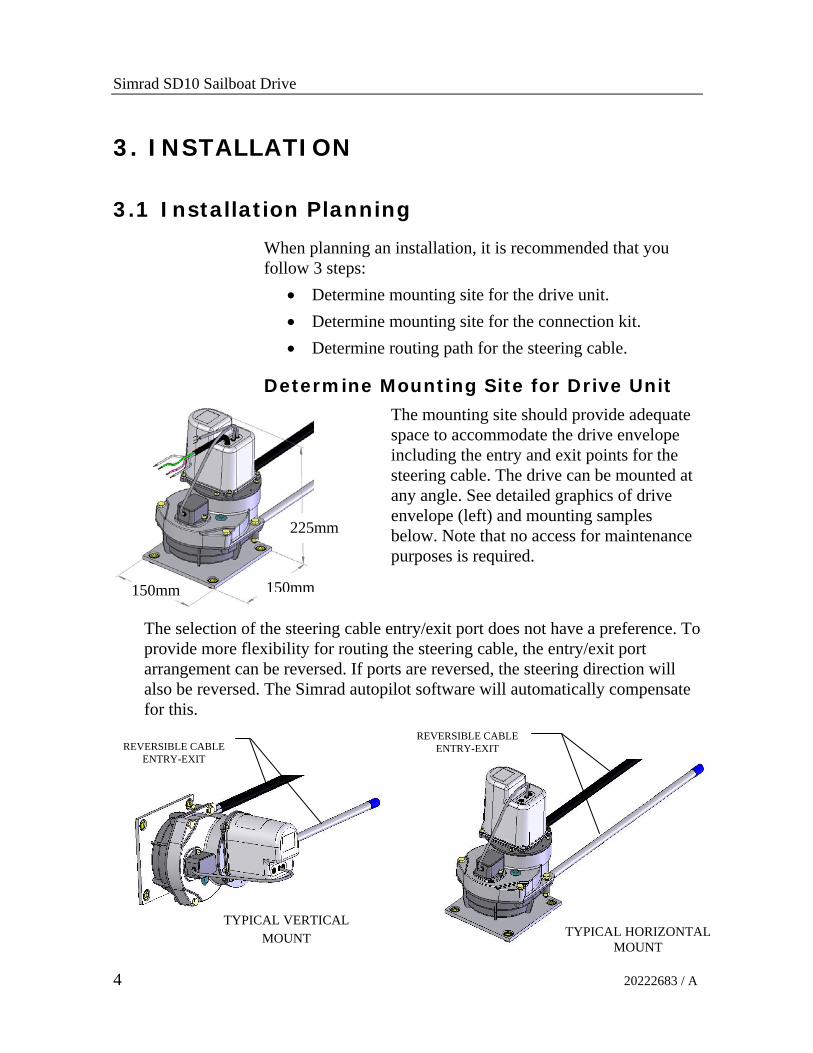
Determine Mounting Site for Drive Unit
The mounting site should provide adequate space to accommodate the drive envelope including the entry and exit points for the steering cable. The drive can be mounted at any angle. See detailed graphics of drive envelope (left) and mounting samples below. Note that no access for maintenance purposes is required.
The selection of the steering cable entry/exit port does not have a preference. To provide more flexibility for routing the steering cable, the entry/exit port arrangement can be reversed. If ports are reversed, the steering direction will also be reversed. The Simrad autopilot software will automatically compensate for this.
TYPICAL VERTICAL MOUNT
REVERSIBLE CABLE ENTRY-EXIT
225mm
150mm150mm
TYPICAL HORIZONTAL MOUNT
REVERSIBLE CABLE ENTRY-EXIT

Installation
20222683 / A 5
Determine Mounting Site for Connection Kit
The Universal Connection Kit must be mounted to stable hull structure. Any orientation is acceptable as long as the HO positions do not force the connection kit beyond its rotation limits. Ideally the connection kit should be mounted so that the thrust from the steering cable is tangential to the tiller arc at mid stroke. It is acceptable to mount the connection kit without using the base plate provided adequate support is available for the hub. The clevis bracket can be mounted to a separate tiller arm or directly to the quadrant if a suitable site is available.
Connection Kit Installation
THREADED GUIDE TUBE (+/- 3 inches of adjustment)
CLEVIS BRACKET
UNIVERSAL HUB (360 degree freedom about vertical axis +/- 40 degrees from horizontal plane)
STEERING CABLE
BASE PLATE CAN BE MOUNTED IN ANY
ORIENTATION (hub can be installed directly onto suitable structure without use of
base plate)
QUICK RELEASE HAIR PIN
GREASE NIPPLE

Simrad SD10 Sailboat Drive
6 20222683 / A
Determine Routing Path for Steering Cable
After the locations for the Connection Kit and Drive Unit have been established, the routing of the Steering Cable must be determined. The cable routing should take into consideration the extreme movements of the steering mechanism during HO to HO steering. Care should be taken to maximize the bend radius and to avoid more than one bend. If more than one bend is required, bends should not be smaller than the minimum bend radius (6”) and the total angle of all bends combined be no larger than 270 degrees. See drawing below showing preferred routing and bend definition. Steering Cable length supplied with system is 6 feet (2 metres). Other lengths are available on request.
Preferred Cable Routing
Determine Length of Custom Steering Cable
If suitable site for drive unit based on a 6 foot steering cable is not available. A custom cable length may be considered. Use a length of rope or electrical cable to simulate the routing, then measure the total length required. See graphic of cable length definition.
‘A’ DIMENSION
MID STROKE
150 mm MIN RADIUS
‘B’ DIMENSION
SPENT CABLE TUBE

Installation
20222683 / A 7
Cable Length Definition
Example of steering cable length calculation: Add ‘A’ + ‘B’ dimensions and subtract 4” for a 90 degree bend. Round UP result to nearest full foot size. For steering cable x length in feet or meter order 21120076 and add x m (ft)
3.2 Installation of Drive Unit - Steering Cable & Spent Cable Tube
Step 1 - Install Drive Unit
1. Remove 2 x lock bolts, nuts and washers from ports and retain.
2. Position drive unit in final location. Verify position by simulating the steering cable connection whilst steering cable is NOT connected.
3. Transfer bolt pattern from the drive base plate (4 x 7 mm (0.28”) diameter holes) into mounting structure.
4. Remove drive unit and prepare holes in mounting structure to receive mounting fasteners (screws, bolts). Note that this
CABLE LENGTH
MID STROKE
Simrad SD10 Sailboat Drive
8 20222683 / A
connection does NOT transmit any steering loads.
5. Re-position drive unit and install fasteners, tighten and torque.
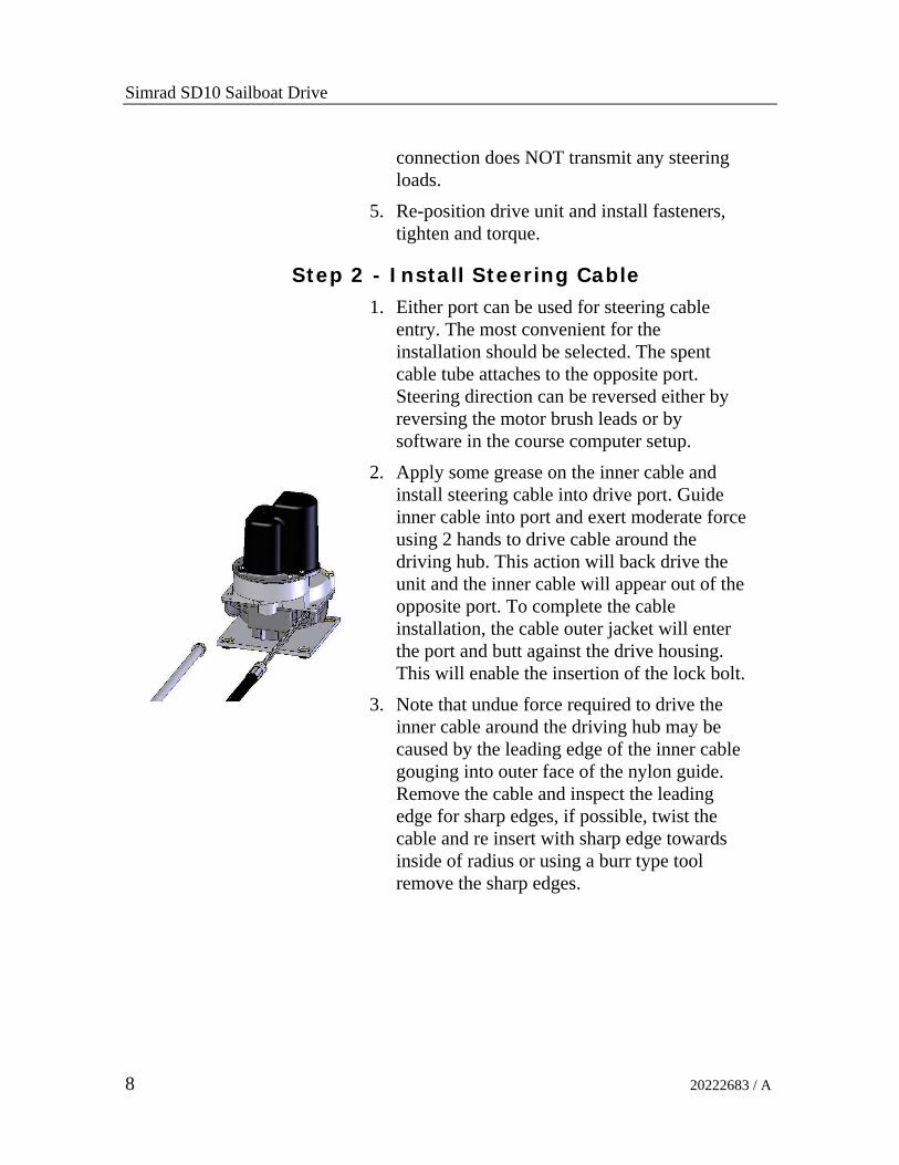
Step 2 - Install Steering Cable
1. Either port can be used for steering cable entry. The most convenient for the installation should be selected. The spent cable tube attaches to the opposite port. Steering direction can be reversed either by reversing the motor brush leads or by software in the course computer setup.
2. Apply some grease on the inner cable and install steering cable into drive port. Guide inner cable into port and exert moderate force using 2 hands to drive cable around the driving hub. This action will back drive the unit and the inner cable will appear out of the opposite port. To complete the cable installation, the cable outer jacket will enter the port and butt against the drive housing. This will enable the insertion of the lock bolt.
3. Note that undue force required to drive the inner cable around the driving hub may be caused by the leading edge of the inner cable gouging into outer face of the nylon guide. Remove the cable and inspect the leading edge for sharp edges, if possible, twist the cable and re insert with sharp edge towards inside of radius or using a burr type tool remove the sharp edges.
Installation
20222683 / A 9
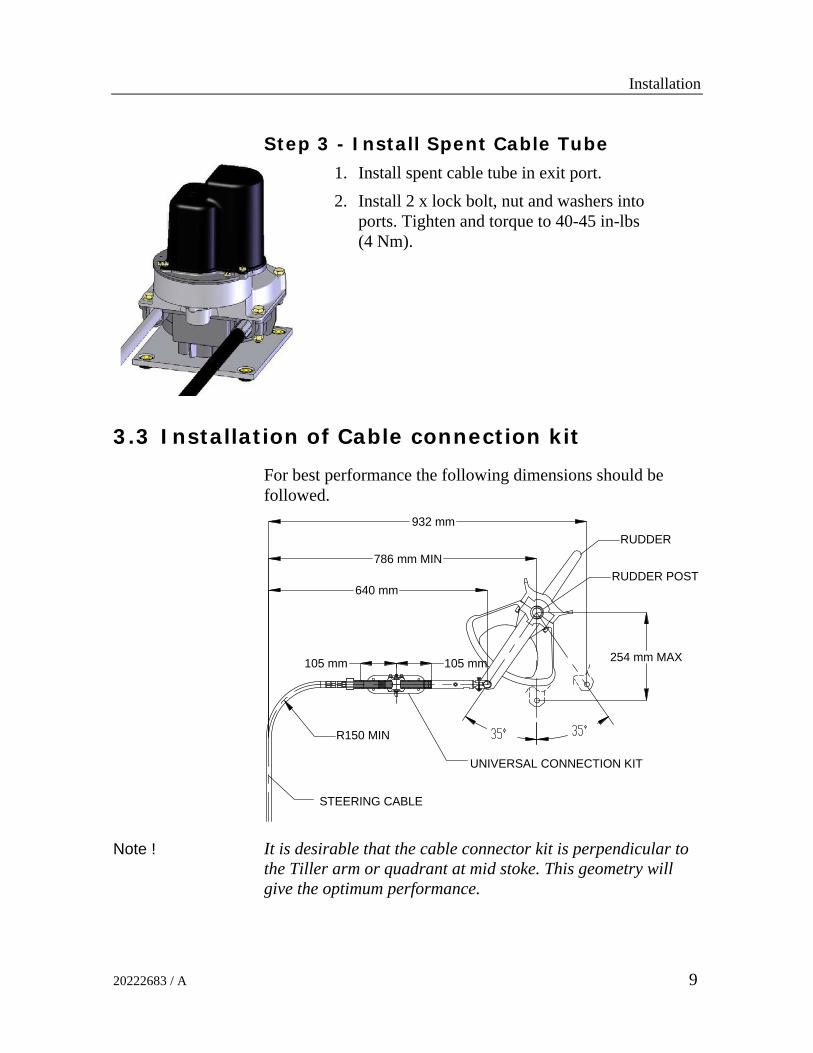
Step 3 - Install Spent Cable Tube
1. Install spent cable tube in exit port. 2. Install 2 x lock bolt, nut and washers into
ports. Tighten and torque to 40-45 in-lbs (4 Nm).
3.3 Installation of Cable connection kit
For best performance the following dimensions should be followed.
105 mm105 mm 254 mm MAX
786 mm MIN
932 mm
640 mm
R150 MIN
RUDDER POST
RUDDER
UNIVERSAL CONNECTION KIT
STEERING CABLE
Note ! It is desirable that the cable connector kit is perpendicular to the Tiller arm or quadrant at mid stoke. This geometry will give the optimum performance.
Simrad SD10 Sailboat Drive
10 20222683 / A
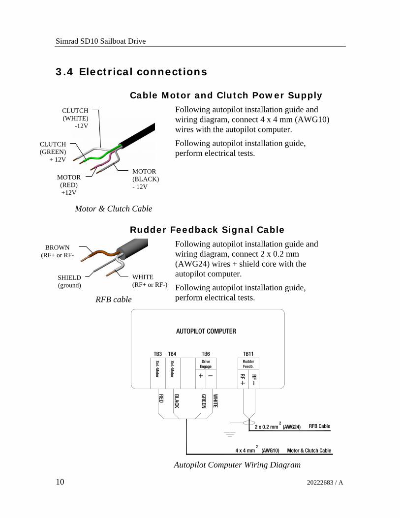
3.4 Electrical connections
Cable Motor and Clutch Power Supply
Motor & Clutch Cable
Following autopilot installation guide and wiring diagram, connect 4 x 4 mm (AWG10) wires with the autopilot computer. Following autopilot installation guide, perform electrical tests.
Rudder Feedback Signal Cable
RFB cable
Following autopilot installation guide and wiring diagram, connect 2 x 0.2 mm (AWG24) wires + shield core with the autopilot computer. Following autopilot installation guide, perform electrical tests.
TB3
Sol.-M
oto
r
Drive
Sol.-M
oto
r
TB4 TB6
Engage
AUTOPILOT COMPUTER
4 x 4 mm2
GR
EE
N
WH
ITE
RE
D
BLA
CK
Rudder
TB11
RF
Feedb.
RF
RFB Cable
(AWG10) Motor & Clutch Cable
2 x 0.2 mm2
(AWG24)
Autopilot Computer Wiring Diagram
MOTOR (RED) +12V
MOTOR (BLACK) - 12V
CLUTCH (GREEN)
+ 12V
CLUTCH (WHITE)
-12V
BROWN (RF+ or RF-
WHITE (RF+ or RF-)
SHIELD(ground)

Mechanical Calibration Procedure
20222683 / A 11
4. MECHANICAL CALIBRATION PROCEDURE
1. Before installing the drive unit into the vessel, disassemble the RFB module from the drive housing, by removing 2 attach screws.
2. Install the drive unit into the vessel and install the remote steering cable following the drive installation guide.
3. Complete the electrical hook up of the drive following the autopilot computer wiring diagram.
4. Centre the gear on the RFB module by aligning the red paint mark on the gear with the red paint mark on the housing as shown in underside view (left).
5. By turning the steering wheel of the helm unit, centre the rudder.
6. Reassemble the RFB module to the drive housing and install and tighten the 2 attach screws. Ensure that the mesh between the RFB module and the drive gear is not excessive.
7. See autopilot manual for instructions on rudder feedback calibration and rudder test.
UNDERSIDEVIEW
ALIGN 2 RED DOTS VERTICALLY
COMPLETE INSTALLATION
RFB MODULE
Simrad SD10 Sailboat Drive
12 20222683 / A
5. MAINTENANCE
Grease the Universal connector kit on installation by applying a grease gun to the grease nipples and at regular intervals thereafter (see page 5). After a few hours of operation and at frequent intervals thereafter, check all fasteners and the complete steering system for security and integrity. Keep all moving parts free from build-up of salt and other foreign material. Build up of salt will effect their operation and create steering problems. Pay particular attention to the Universal connector kit. Periodically remove the cable, clean the connector tube and thoroughly lubricate with waterproof grease. Inspect periodically for corrosion. Any parts affected by corrosion must be replaced. When replacing hardware, self-locking hardware must be used. Inspect steering cable periodically for cracks or other damage. If any is found the cable must be replaced.
WARNING ! Do NOT cover cracks in the cable with tape or other sealants; this will only delay a fatal failure of the cable. Always replace the cable.

Serviceable Parts
20222683 / A 13
6. SERVICEABLE PARTS
Main Components Part numbers 21120001 SD10 Complete drive 21120027 SD10 Rudder feedback module 21120035 SD10 Drive Motor 21120043 SD10 Rudder Feedback PCB 21120050 SD10 Solenoid 21120068 SD10 Linear Universal Kit 21120076 SD10 Cable, 2 m (6’)
RFB – PCB
CLUTCH SOLENOID
DRIVE MOTOR RFB – MODULE
Simrad SD10 Sailboat Drive
14 20222683 / A
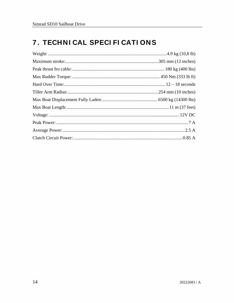
7. TECHNICAL SPECIFICATIONS Weight: .......................................................................................................4.9 kg (10,8 lb)
Maximum stroke:.................................................................................305 mm (12 inches)
Peak thrust fro cable: ................................................................................ 180 kg (400 lbs)
Max Rudder Torque: ............................................................................ 450 Nm (333 lb ft)
Hard Over Time:........................................................................................12 – 18 seconds
Tiller Arm Radius:...............................................................................254 mm (10 inches)
Max Boat Displacement Fully Laden:................................................ 6500 kg (14300 lbs)
Max Boat Length:.........................................................................................11 m (37 feet)
Voltage: ................................................................................................................. 12V DC
Peak Power: ...................................................................................................................7 A
Average Power: ..........................................................................................................2.5 A
Clutch Circuit Power: ...............................................................................................0.85 A