Simrad IS15 Wind Manual - NUOVA MAREA LTDnuovamarea.com/files/product...
44
MANUAL Simrad IS15 Wind
Transcript of Simrad IS15 Wind Manual - NUOVA MAREA LTDnuovamarea.com/files/product...

MANUAL
Simrad IS15 Wind

This page is intentionally left blank
IS15 Wind Manual
20220752J 1
This manual is intended as a reference guide for installing and using the analog IS15 Wind and IS15 Tack instruments and the IS15 Wind Transducer (masthead unit).
Please take time to read the manual to get a thorough understanding of the operation and system components and their relationship to a complete IS15 instrument system.
Other documentation material that is provided with your system includes a ‘bridge card’, and warranty card. The warranty card must be filled out by the authorized dealer that performed the installation and mailed in to activate the warranty. You will find the warranty card in this manual.

IS15 Wind Manual
2 20220752J
Document revisions
Rev Date Written by Checked by Approved by
D 100300 NG ThH
E 091100 NG ThH
F 191200 NG ThH
G 080202 NG ThH
H 230502 NG ThH
I 300403 NG ThH
J 300305 NG ThH
Document history Rev. D Addendum from rev. C implemented. Roblink Power Cable and IS15
Power Supply included. Chapter 5.7 added describing IS15 as NMEA repeaters.
Rev. E Fault Finding, Maintenance and Spare Parts List included. Updated to software version V1R3.
Rev. F Chapter 4.2 ‘Instrument Software Information’ added. Rev. G Minor changes. Complies with software version V1R5. Rev. H Changes to comply with software version V1R6. Rev. I Minor corrections in text. Rev. J 1 Amp fuse included in Roblink Power Cable, Figure 1-1 and 5-3.
IS15 Wind Manual
20220752J 3
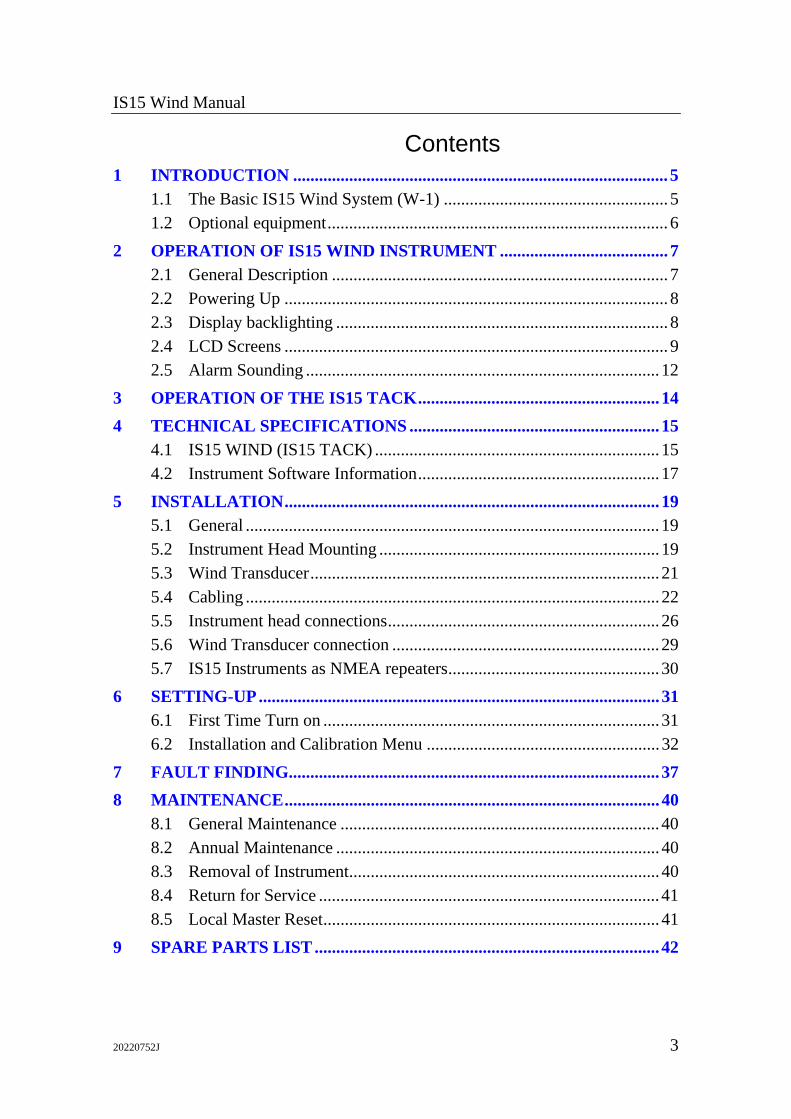
Contents 1 INTRODUCTION ....................................................................................... 5
1.1 The Basic IS15 Wind System (W-1) .................................................... 5 1.2 Optional equipment............................................................................... 6
2 OPERATION OF IS15 WIND INSTRUMENT ....................................... 7 2.1 General Description .............................................................................. 7 2.2 Powering Up ......................................................................................... 8 2.3 Display backlighting ............................................................................. 8 2.4 LCD Screens ......................................................................................... 9 2.5 Alarm Sounding .................................................................................. 12
3 OPERATION OF THE IS15 TACK........................................................ 14 4 TECHNICAL SPECIFICATIONS .......................................................... 15
4.1 IS15 WIND (IS15 TACK) .................................................................. 15 4.2 Instrument Software Information........................................................ 17
5 INSTALLATION....................................................................................... 19 5.1 General ................................................................................................ 19 5.2 Instrument Head Mounting ................................................................. 19 5.3 Wind Transducer................................................................................. 21 5.4 Cabling ................................................................................................ 22 5.5 Instrument head connections............................................................... 26 5.6 Wind Transducer connection .............................................................. 29 5.7 IS15 Instruments as NMEA repeaters................................................. 30
6 SETTING-UP............................................................................................. 31 6.1 First Time Turn on .............................................................................. 31 6.2 Installation and Calibration Menu ...................................................... 32
7 FAULT FINDING...................................................................................... 37 8 MAINTENANCE....................................................................................... 40
8.1 General Maintenance .......................................................................... 40 8.2 Annual Maintenance ........................................................................... 40 8.3 Removal of Instrument........................................................................ 40 8.4 Return for Service ............................................................................... 41 8.5 Local Master Reset.............................................................................. 41
9 SPARE PARTS LIST ................................................................................ 42

IS15 Wind Manual
4 20220752J
This page is intentionally left blank.

Introduction
20220752J 5
1 INTRODUCTION
1.1 The Basic IS15 Wind System (W-1) A basic stand alone Wind System comprises the following:
• IS15 Wind instrument w.: Mounting kit, 0,3 m (1’) IS15 (Roblink) Cable and Operator’s Quick Reference Guide (“bridge card”).
• IS15 Wind Transducer w.: Mounting accessories, 30 m (99’) mast cable, junction box, 10 m (33’) IS15 (Roblink) Cable and manual.
• Roblink Power Cable: Special power cable 2,5 m (8’).
Note ! This cable is only required when using a single IS15 Wind instrument as stand alone, see Figure 1-1.
The units must be interconnected as per below.
WindTransducer
IS15 WindSIMRAD
Junction box (mast foot)Supply 10,8-15,6VDC
10m (33')30m (99')
Speed/headinginput on NMEA
Circuitbreaker
***
Roblink cable with connector(Special) Roblink Power Cable
***Fuse
1A Slow+
Figure 1-1 Basic IS15 Wind System
Note ! If no input is available on NMEA 0183 format, the above instrument system will only display apparent wind speed and angle. Refer to Chapter 5.4 for more information.
IS15 Wind Manual
6 20220752J
1.2 Optional equipment • IS15 Cable 2 m (6,5’) P/N 22093728
• IS15 Cable 5 m (16’) P/N 22092548
• IS15 Cable 10 m (33’) P/N 22092027 The cables can be used for extension and/or as cables for NMEA interface to peripheral equipment.
• IS15 Cable Adapter (joiner) P/N 22092001 Interconnects IS15 cables where cable extension is required.
• Roblink Power Cable 2,5 m (8’) P/N 22093587. Required when using 2 or 3 instrument heads as NMEA repeaters in a “daisy chain”. Comes as standard with a W-1 system, see previous page.
• IS15 Power Supply P/N 22093595. Required when using 4-7 instrument heads as NMEA repeaters in a “daisy chain”.

Operation
20220752J 7
2 OPERATION OF IS15 WIND INSTRUMENT
2.1 General Description The display is divided into two sections, the scale with pointer, and the LCD. Both are controlled by the two buttons.
The Scale The pointer indicates apparent or true wind angle, depending on the mode selected.
The LCD Display During normal operation the LCD shows one of the items below:
• Apparent Wind Speed.
• True Wind Speed.
• Velocity Made Good to Wind (VMG)
• Wind Direction, (requires Heading or Course Over Ground and Water Speed or Speed Over Ground input to the instrument) see page 10.
Pointer
Left b
Right button LCD display
Scale
Arrow
LCD Arrow legend
IS15 Wind Manual
8 20220752J
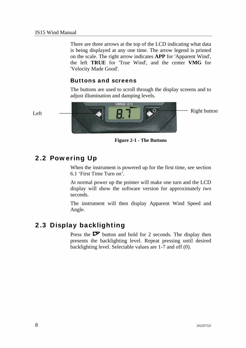
There are three arrows at the top of the LCD indicating what data is being displayed at any one time. The arrow legend is printed on the scale. The right arrow indicates APP for 'Apparent Wind', the left TRUE for 'True Wind', and the center VMG for 'Velocity Made Good'.
Buttons and screens The buttons are used to scroll through the display screens and to adjust illumination and damping levels.
Figure 2-1 - The Buttons
2.2 Powering Up When the instrument is powered up for the first time, see section 6.1 ‘First Time Turn on’. At normal power up the pointer will make one turn and the LCD display will show the software version for approximately two seconds. The instrument will then display Apparent Wind Speed and Angle.
2.3 Display backlighting Press the button and hold for 2 seconds. The display then presents the backlighting level. Repeat pressing until desired backlighting level. Selectable values are 1-7 and off (0).
Left Right button
Operation
20220752J 9
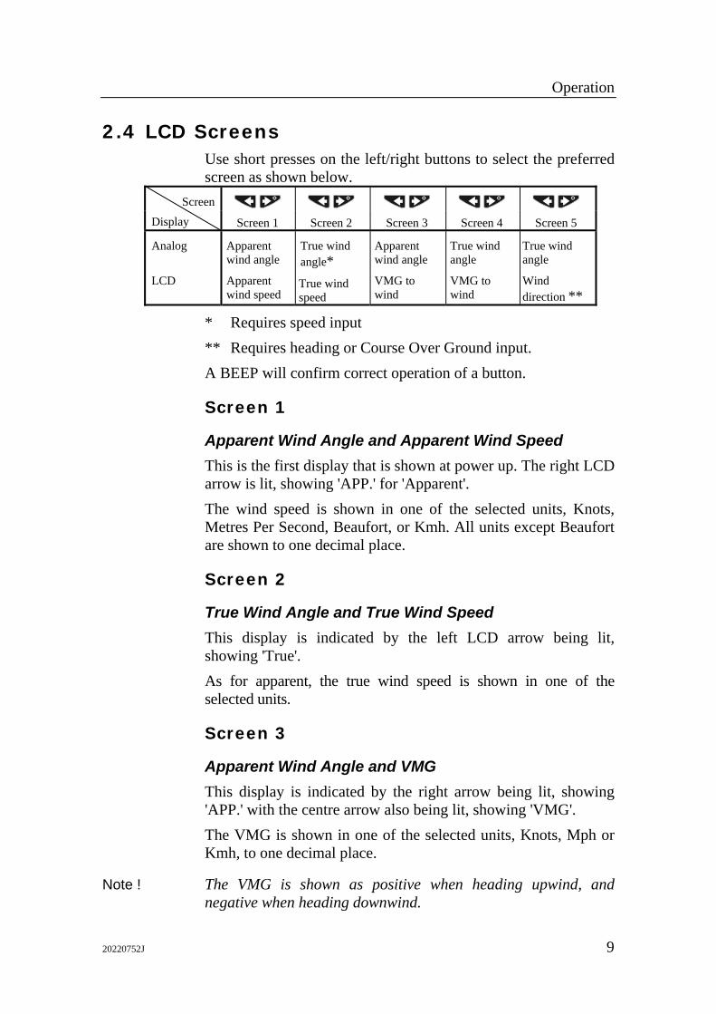
2.4 LCD Screens Use short presses on the left/right buttons to select the preferred screen as shown below.
Screen
Display
Screen 1
Screen 2
Screen 3
Screen 4
Screen 5
Analog LCD
Apparent wind angle
Apparent wind speed
True wind angle*
True wind speed
Apparent wind angle
VMG to wind
True wind angle
VMG to wind
True wind angle
Wind direction **
* Requires speed input ** Requires heading or Course Over Ground input. A BEEP will confirm correct operation of a button.
Screen 1
Apparent Wind Angle and Apparent Wind Speed This is the first display that is shown at power up. The right LCD arrow is lit, showing 'APP.' for 'Apparent'. The wind speed is shown in one of the selected units, Knots, Metres Per Second, Beaufort, or Kmh. All units except Beaufort are shown to one decimal place.
Screen 2
True Wind Angle and True Wind Speed This display is indicated by the left LCD arrow being lit, showing 'True'. As for apparent, the true wind speed is shown in one of the selected units.
Screen 3
Apparent Wind Angle and VMG This display is indicated by the right arrow being lit, showing 'APP.' with the centre arrow also being lit, showing 'VMG'. The VMG is shown in one of the selected units, Knots, Mph or Kmh, to one decimal place.
Note ! The VMG is shown as positive when heading upwind, and negative when heading downwind.
IS15 Wind Manual
10 20220752J
Screen 4
True Wind Angle and VMG This display is indicated by the left LCD arrow being lit, showing 'True' (Wind Angle). Otherwise similar to the Apparent Wind Angle and VMG display.
Screen 5
True Wind Angle and Wind Direction This display is indicated by the left LCD arrow being lit, showing 'True' (Wind Angle), with the LCD showing the wind direction in degrees.
Notes ! 1. The Wind Direction is calculated from available heading
data. The wind direction given is the effective wind direction over the water. The display will be most accurate after a period on one heading, however, it will respond rapidly to course changes.
2. If there is no heading data, but Course Over Ground (COG) data is available then the Wind Direction is calculated from the Course Over Ground. In this case there is compensation for the tide, and the wind direction given is the effective wind direction over the ground. However the display will not be accurate after a course change, and will require a period on one heading before it is correct. (Any errors in the Navigation Receiver’s fix will degrade the accuracy of the wind direction.)
3. The Wind Direction is referenced to either Magnetic or True North as selected for the heading. The data can be converted from one to the other if the local magnetic variation is available.
Sub screens All main LCD screens have the same three sub screens to set the following: Display damping, (true) Wind Speed Alarm On/Off and (true) Wind Speed Alarm Limit. Press and hold the button for 2 seconds to access the sub-screens. Use short presses on the button to select one of the sub screens.
Operation
20220752J 11
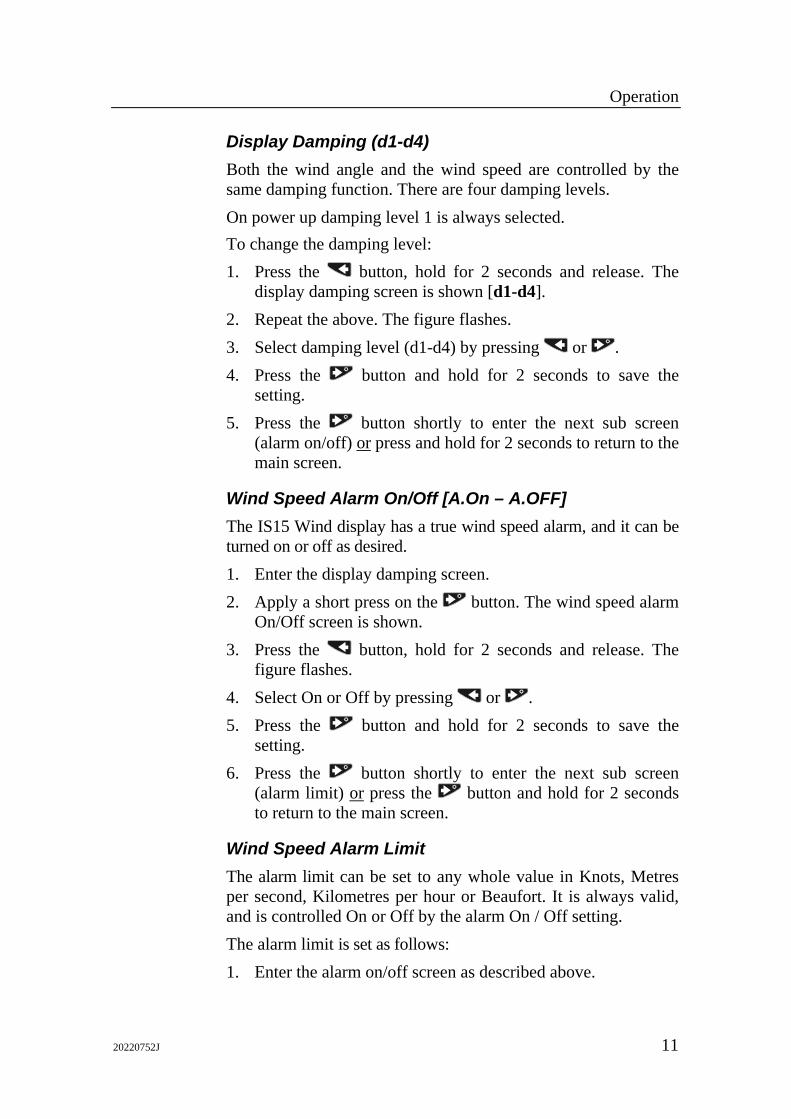
Display Damping (d1-d4) Both the wind angle and the wind speed are controlled by the same damping function. There are four damping levels. On power up damping level 1 is always selected. To change the damping level: 1. Press the button, hold for 2 seconds and release. The
display damping screen is shown [d1-d4]. 2. Repeat the above. The figure flashes. 3. Select damping level (d1-d4) by pressing or . 4. Press the button and hold for 2 seconds to save the
setting. 5. Press the button shortly to enter the next sub screen
(alarm on/off) or press and hold for 2 seconds to return to the main screen.
Wind Speed Alarm On/Off [A.On – A.OFF] The IS15 Wind display has a true wind speed alarm, and it can be turned on or off as desired. 1. Enter the display damping screen. 2. Apply a short press on the button. The wind speed alarm
On/Off screen is shown. 3. Press the button, hold for 2 seconds and release. The
figure flashes. 4. Select On or Off by pressing or . 5. Press the button and hold for 2 seconds to save the
setting. 6. Press the button shortly to enter the next sub screen
(alarm limit) or press the button and hold for 2 seconds to return to the main screen.
Wind Speed Alarm Limit The alarm limit can be set to any whole value in Knots, Metres per second, Kilometres per hour or Beaufort. It is always valid, and is controlled On or Off by the alarm On / Off setting. The alarm limit is set as follows: 1. Enter the alarm on/off screen as described above.

IS15 Wind Manual
12 20220752J
2. Apply a short press on the button. The wind speed alarm limit screen is shown.
3. Press the button, hold for 2 seconds and release. The current value will be shown flashing.
4. Increase the alarm value using the button. 5. Decrease the alarm value using the button. 6. Press the button, hold for 2 seconds and release to save
the limit setting. 7. Press the button and hold for 2 seconds to return to the
main screen.
2.5 Alarm Sounding Alarms are system wide and all the instruments will sound and flash a warning message. If there is an external alarm connected this will sound at the same time (only if an IS15 Expander is part of the system). To cancel a sounding alarm press any button on any of the instrument heads.
Note ! The flashing warning will remain as long as the alarm condition exists and disappears automatically when there is no longer an alarm condition. The sounding alarm will always have to be cancelled.
Alarm messages The symbols that are shown when an alarm is triggered are as below: ‘SHAL’ = The Shallow Water Alarm ‘dEEP’ = The Deep Water Alarm ‘AnCH’ = The Anchor Alarm ‘HIGH’ = The High Wind Speed Alarm ‘Er.XX’ = System failure (Contact your Simrad dealer).
Operation
20220752J 13
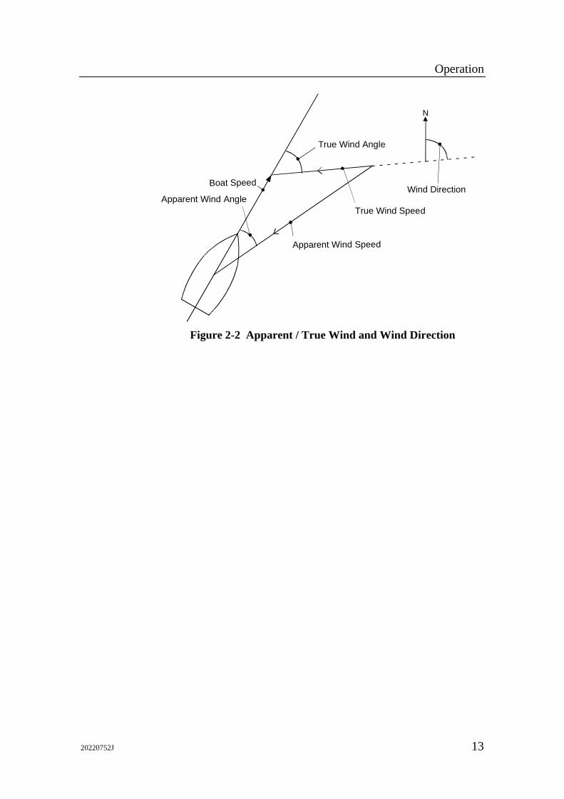
Apparent Wind Angle
True Wind Angle
Apparent Wind Speed
True Wind Speed
Boat SpeedWind Direction
N
Figure 2-2 Apparent / True Wind and Wind Direction

IS15 Wind Manual
14 20220752J
3 OPERATION OF THE IS15 TACK
The IS15 Tack has basically the same functions as IS15 Wind. The difference is the magnified wind angle scale which makes it useful when sailing close hauled or running down wind. The operation of IS15 Tack is identical to that of IS15 Wind with the same screen menus on the LCD. Refer to Sections 2 and 6 for further information.
Scale
Pointer
Left push button
Right push button
LCD display
ArrowLCD arrows legend
Technical Specifications
20220752J 15
4 TECHNICAL SPECIFICATIONS
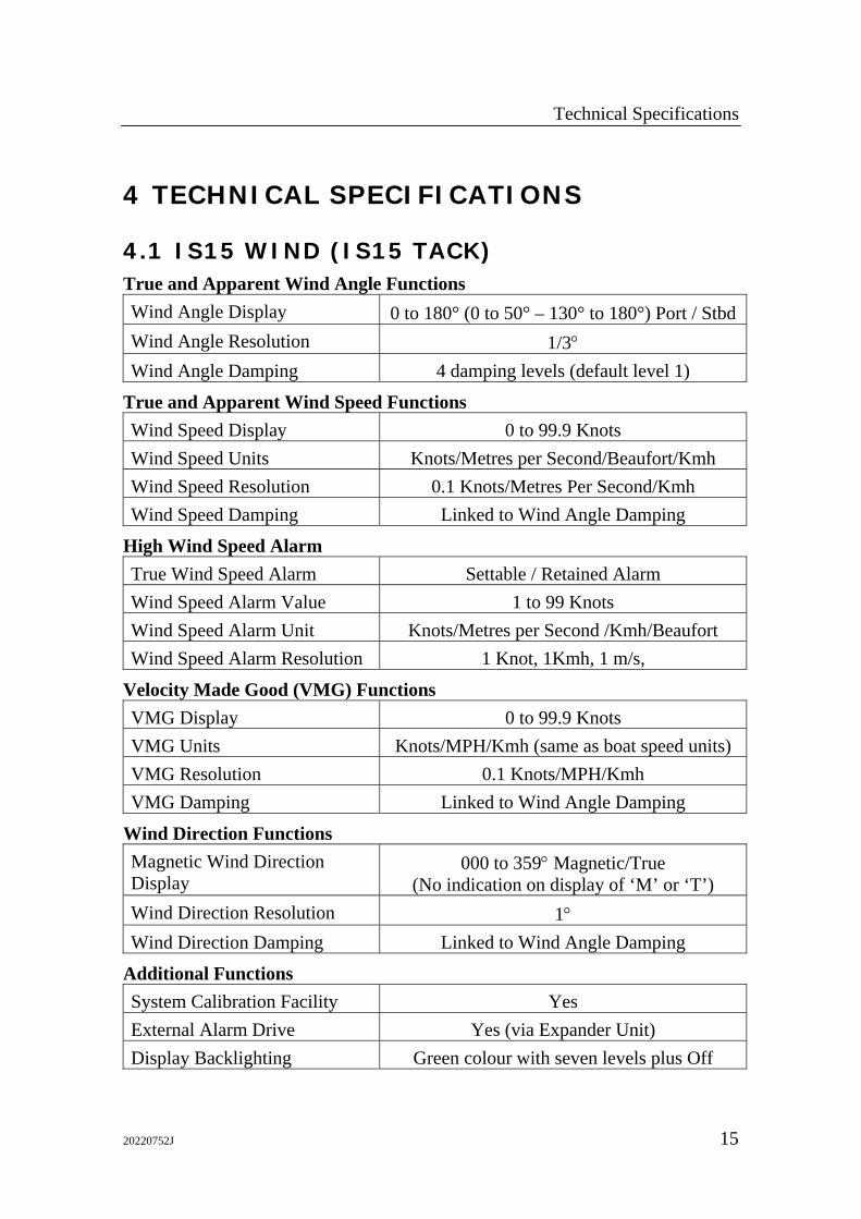
4.1 IS15 WIND (IS15 TACK) True and Apparent Wind Angle Functions Wind Angle Display 0 to 180° (0 to 50° – 130° to 180°) Port / Stbd Wind Angle Resolution 1/3° Wind Angle Damping 4 damping levels (default level 1)
True and Apparent Wind Speed Functions Wind Speed Display 0 to 99.9 Knots Wind Speed Units Knots/Metres per Second/Beaufort/Kmh Wind Speed Resolution 0.1 Knots/Metres Per Second/Kmh Wind Speed Damping Linked to Wind Angle Damping
High Wind Speed Alarm True Wind Speed Alarm Settable / Retained Alarm Wind Speed Alarm Value 1 to 99 Knots Wind Speed Alarm Unit Knots/Metres per Second /Kmh/Beaufort Wind Speed Alarm Resolution 1 Knot, 1Kmh, 1 m/s,
Velocity Made Good (VMG) Functions VMG Display 0 to 99.9 Knots VMG Units Knots/MPH/Kmh (same as boat speed units) VMG Resolution 0.1 Knots/MPH/Kmh VMG Damping Linked to Wind Angle Damping
Wind Direction Functions Magnetic Wind Direction Display
000 to 359° Magnetic/True (No indication on display of ‘M’ or ‘T’)
Wind Direction Resolution 1° Wind Direction Damping Linked to Wind Angle Damping
Additional Functions System Calibration Facility Yes External Alarm Drive Yes (via Expander Unit) Display Backlighting Green colour with seven levels plus Off

IS15 Wind Manual
16 20220752J
Display Backlighting Control Two independent lighting banks or individual settings (bank 0)
Wind data Output via NMEA port
General Power Requirement 10,8 to 15,6VDC, 70 mA, (100 mA with max.
lighting) Size See Figure 4-1 Weight 225 grams Environmental Protection IP56 from front, IP44 from rear Temperature Range Operation: 0°C to +55°C (+32 to +130°F)
Storage: -30°C to +80°C (-22 to +176°F)
110
mm
[4,3
3"]
21 mm[0,83"]
30 mm[1,18"]
85 mm Dia[3,35"].(Panel cut-out)
32 mm[1,26"]
110
mm
[4,3
3"]
110 mm [4,33"]
9 mm[0,35"]
Figure 4-1 IS15 Dimensions
210
mm
(8.2
in)
600 mm (23.6 in)
178 mm (7 in)
345
mm
(13.
6 in
)
Figure 4-2 IS15 Wind Transducer
Technical Specifications
20220752J 17
4.2 Instrument Software Information V1R1: Beta version, not used in ordinary production. V1R2: First production version V1R3: Upgraded version with added features.
• Trip log replaces sea temperature on first screen of IS15 Combi.
• In Locked Course mode the LCD on IS15 Compass has been changed to show deviation in degrees from locked course.
• Improved log calibration procedure. Possible to set Log reading as percent (%) of default value. Log calibration can be set to same value on identical boats.
• Boat speed always reads 0.0 at zero speed. (V1R2 may show - - - at turn on and a ‘residual’ speed value when slowing down to zero speed).
• Improved boat speed and wind speed damping.
• Improved damping of heading displays.
• Depth transducer remains OFF at turn on if it was set to OFF while the system was running.
• Test screens added to Installation Menu to simplify trouble shooting.
• Roblink can be turned off and thus eliminate a possible interference when a single instrument is connected as NMEA repeater.
• ‘Communication reset’ added. Saves all settings in the event an anomaly in the system functions calls for a reset.
V1R4: Substitutes V1R3 that contains a bug. V1R3 should not be used. V1R5: More features added. Not released, replaced by V1R6.
• Manual setting (In/Out) of NMEA port added.
• Wind offset also applies when wind data is from an external NMEA source.
V1R6: New software to comply with PCB Ass’y Revision H (B on round heads) onwards. V1R6 is backwards compatible with previous software and hardware versions.

IS15 Wind Manual
18 20220752J
Notes! 1. PCB Ass’y with this revision does not accept V1R2 or V1R4
software. 2. V1R6 is backward compatible with V1R2 and V1R4.
However, anomalies may be observed if attention is not being paid to the NMEA interface. In systems with mixed software, do not interface NMEA ‘talkers’ to heads with V1R2 software.
Installation
20220752J 19
5 INSTALLATION
5.1 General This section provides detailed information required to successfully install an IS15 Instrument System utilising the IS15 Wind, IS15 Tack and IS15 Wind Transducer unit. It also describes the connection to peripheral equipment and interconnection with other types of IS15 instruments.
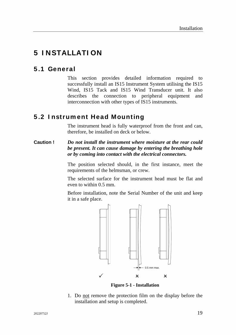
5.2 Instrument Head Mounting The instrument head is fully waterproof from the front and can, therefore, be installed on deck or below.
Caution ! Do not install the instrument where moisture at the rear could be present. It can cause damage by entering the breathing hole or by coming into contact with the electrical connectors.
The position selected should, in the first instance, meet the requirements of the helmsman, or crew. The selected surface for the instrument head must be flat and even to within 0.5 mm. Before installation, note the Serial Number of the unit and keep it in a safe place.
0.5 mm max.
Figure 5-1 - Installation
1. Do not remove the protection film on the display before the installation and setup is completed.
IS15 Wind Manual
20 20220752J
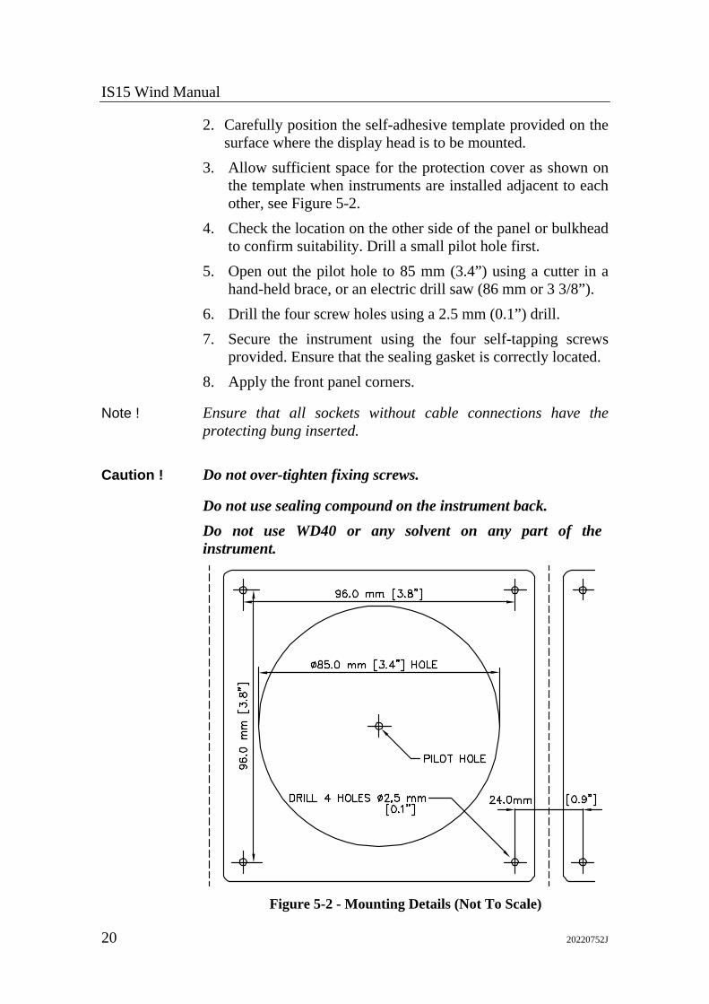
2. Carefully position the self-adhesive template provided on the surface where the display head is to be mounted.
3. Allow sufficient space for the protection cover as shown on the template when instruments are installed adjacent to each other, see Figure 5-2.
4. Check the location on the other side of the panel or bulkhead to confirm suitability. Drill a small pilot hole first.
5. Open out the pilot hole to 85 mm (3.4”) using a cutter in a hand-held brace, or an electric drill saw (86 mm or 3 3/8”).
6. Drill the four screw holes using a 2.5 mm (0.1”) drill. 7. Secure the instrument using the four self-tapping screws
provided. Ensure that the sealing gasket is correctly located. 8. Apply the front panel corners.
Note ! Ensure that all sockets without cable connections have the protecting bung inserted.
Caution ! Do not over-tighten fixing screws.
Do not use sealing compound on the instrument back. Do not use WD40 or any solvent on any part of the instrument.
Figure 5-2 - Mounting Details (Not To Scale)
Installation
20220752J 21
5.3 Wind Transducer
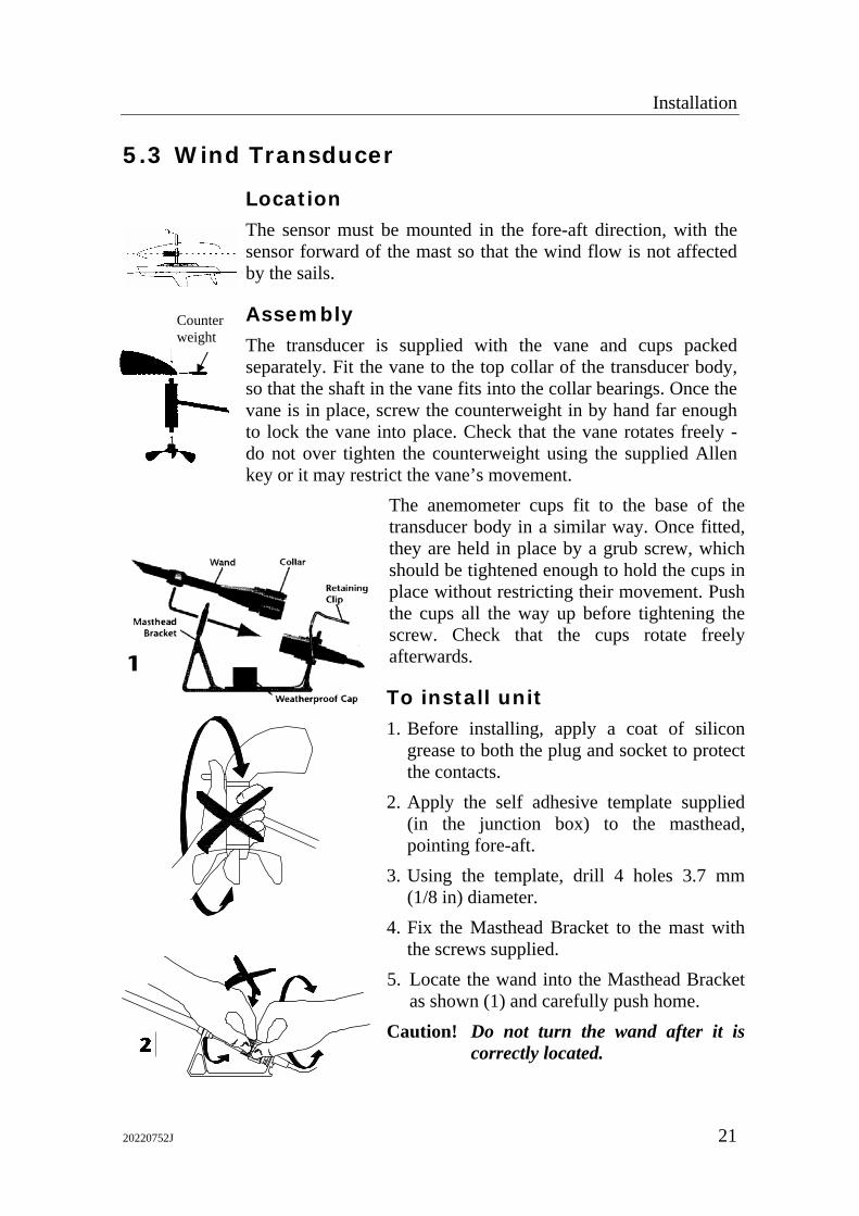
Location The sensor must be mounted in the fore-aft direction, with the sensor forward of the mast so that the wind flow is not affected by the sails.
Assembly The transducer is supplied with the vane and cups packed separately. Fit the vane to the top collar of the transducer body, so that the shaft in the vane fits into the collar bearings. Once the vane is in place, screw the counterweight in by hand far enough to lock the vane into place. Check that the vane rotates freely - do not over tighten the counterweight using the supplied Allen key or it may restrict the vane’s movement.
The anemometer cups fit to the base of the transducer body in a similar way. Once fitted, they are held in place by a grub screw, which should be tightened enough to hold the cups in place without restricting their movement. Push the cups all the way up before tightening the screw. Check that the cups rotate freely afterwards.
To install unit 1. Before installing, apply a coat of silicon
grease to both the plug and socket to protect the contacts.
2. Apply the self adhesive template supplied (in the junction box) to the masthead, pointing fore-aft.
3. Using the template, drill 4 holes 3.7 mm (1/8 in) diameter.
4. Fix the Masthead Bracket to the mast with the screws supplied.
5. Locate the wand into the Masthead Bracket as shown (1) and carefully push home.
Caution! Do not turn the wand after it is correctly located.
Counter weight
IS15 Wind Manual
22 20220752J
6. When the wand is correctly in position, screw down the collar until it is HAND tight (2).
7. Lock the retaining clip into place (3). Note ! Remove the wand in the reverse order.
8. The cable is easily threaded down the mast if a pull-through cord or mouse has been left for that purpose. If there is no mouse, it may help to fix a weight to the end of the cable to assist its passage through the mast.
9. If there is a small error in the alignment of the masthead unit, this can be compensated for. Please refer to the relevant calibration instructions for more details.
Note ! The masthead bracket includes an integral weatherproof cap that should always be fitted to the socket if the wand has been removed.
5.4 Cabling
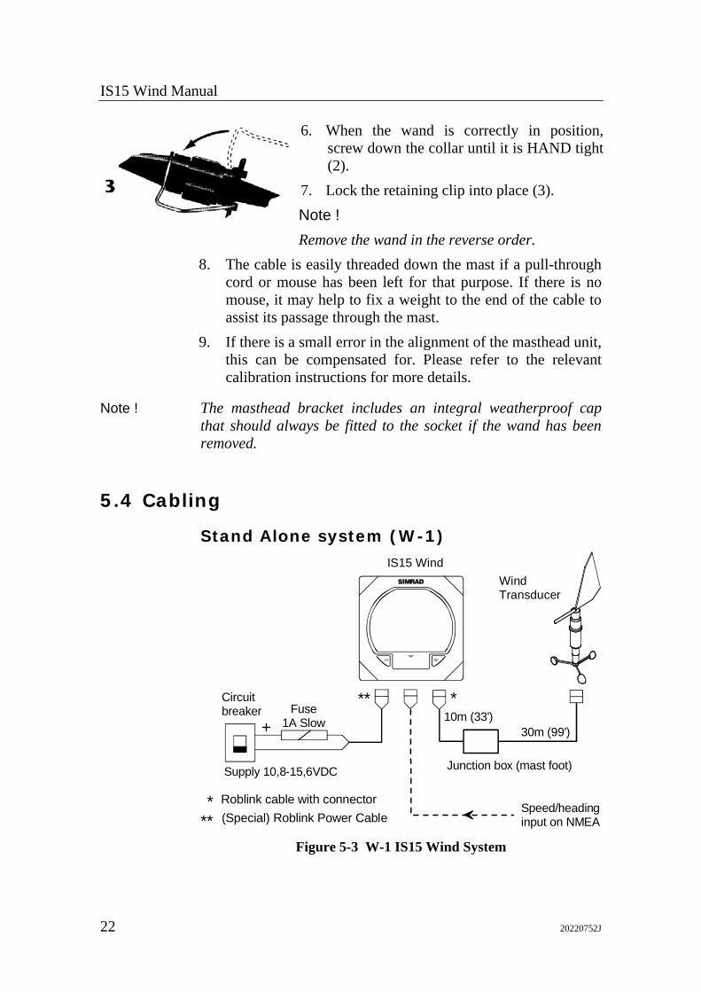
Stand Alone system (W-1)
WindTransducer
IS15 WindSIMRAD
Junction box (mast foot)Supply 10,8-15,6VDC
10m (33')30m (99')
Speed/headinginput on NMEA
Circuitbreaker
***
Roblink cable with connector(Special) Roblink Power Cable
***Fuse
1A Slow+
Figure 5-3 W-1 IS15 Wind System
Installation
20220752J 23
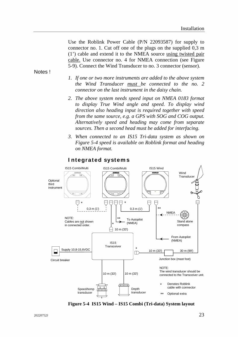
Use the Roblink Power Cable (P/N 22093587) for supply to connector no. 1. Cut off one of the plugs on the supplied 0,3 m (1’) cable and extend it to the NMEA source using twisted pair cable. Use connector no. 4 for NMEA connection (see Figure 5-9). Connect the Wind Transducer to no. 3 connector (sensor).
Notes ! 1. If one or two more instruments are added to the above system
the Wind Transducer must be connected to the no. 2 connector on the last instrument in the daisy chain.
2. The above system needs speed input on NMEA 0183 format to display True Wind angle and speed. To display wind direction also heading input is required together with speed from the same source, e.g. a GPS with SOG and COG output. Alternatively speed and heading may come from separate sources. Then a second head must be added for interfacing.
3. When connected to an IS15 Tri-data system as shown on Figure 5-4 speed is available on Roblink format and heading on NMEA format.
Integrated systems
Speed/temp transducer
Depthtransducer
Supply 10,8-15,6VDC
SIMRAD
IS15 Combi/Multi
10 m (33') 10 m (33')
10 m (33')
IS15Transceiver
SIMRAD
0,3 m (1')
IS15 Combi/MultiWindTransducer
IS15 WindSIMRAD
Junction box (mast foot)
0,3 m (1')
10 m (33') 30 m (99')
From Autopilot(NMEA)
Stand alone compass
NMEA
To Autopilot(NMEA)
NOTE:The wind transducer should be connected to the Transceiver unit.
NOTE:Cables are not shownin connected order.
Circuit breaker
Optional third instrument
* *
*
*
**
**
Denotes Roblinkcable with connector
Optional extra
*
** Figure 5-4 IS15 Wind – IS15 Combi (Tri-data) System layout
IS15 Wind Manual
24 20220752J
Spee
d/te
mp
trans
duce
rD
epth
trans
duce
r
Supp
ly 1
0,8-
15,6
VDC
SIMRAD
Win
dTr
ansd
ucer*
SIMRAD
*
**
IS15
Mul
ti (S
peed
)SIMRAD
SIMRAD
**
0,3m
(1')
10m
(33'
)30
m (9
9')
0,3m
(1')
0,3m
(1')
10m
(33'
)10
m (3
3')
10m
(33'
) IS15
Tran
scei
ver
Junc
tion
box
(mas
t foo
t)
SIMRAD
SIMRAD
SIMRAD
**
0,3m
(1')
0,3m
(1')
*
5-10
m (1
6-33
')
IS15
Mul
ti (D
epth
)IS
15 W
ind
IS15
Com
pass
IS15
Mul
ti (S
peed
)IS
15 M
ulti
(Dep
th)
IS15
Com
pass
Gro
up n
o. 1
Gro
up n
o. 2
The
orde
r of i
nstru
men
t int
erco
nnec
tion
may
be
any
pref
erre
d or
der.
Not
e:
*R
oblin
k da
ta B
us
Rob
link
Cab
le/C
onne
ctor
Win
d Tr
ansd
ucer
Con
nect
or
**N
MEA
dat
a
From
Aut
opilo
t
To A
utop
ilot
From
Cha
rtplo
tter (
NM
EA)
To R
adar
To C
hartp
lotte
r (N
MEA
)
****
****
**
To R
adar
(alte
rnat
ive)
To C
hartp
lotte
r(a
ltern
ativ
e)
To V
HF
radi
o**
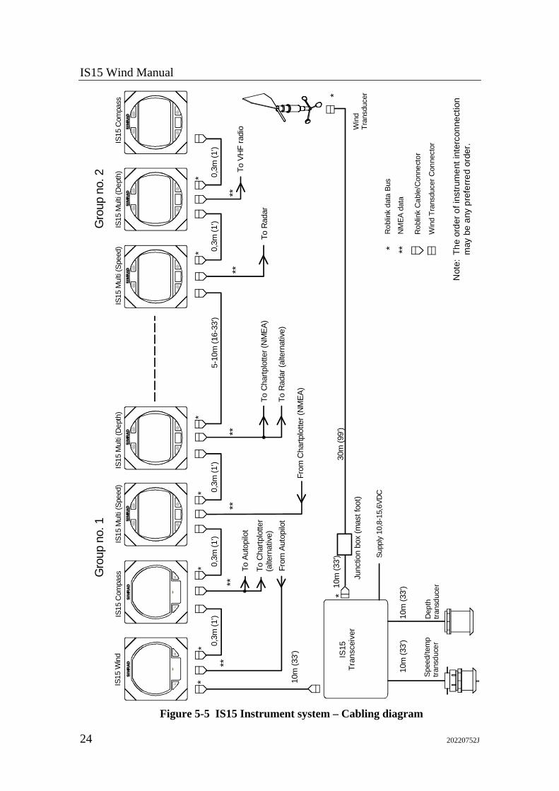
Figure 5-5 IS15 Instrument system – Cabling diagram
Installation
20220752J 25
An example of a fully equipped IS 15 system is shown in Figure 5-5. See also the Interconnection – Principle diagram Figure 6-5 in the IS15 General Manual.
Choosing the Cable Routes When routing the cables choose the most direct paths while avoiding the following hazards: • Sharp bends or kinks in the cable • Hot surfaces (exhaust manifolds or cooking equipment) • Rotating or reciprocating equipment • Sharp or abrasive surfaces • Door and window jambs • Corrosive fluids or gases
Extending Cables Refer to page 6 for information.
Note ! The total length of (Roblink) cables in a system should not exceed 30 m not including the cable to the Wind Transducer. Refer to section 6.6 in IS15 General Manual.
Securing the Cables After the ideal cable routing has been established, use tie-wraps, ‘P’ - clips or other fixings to secure the cables along the routings.
Note ! To prevent chafing add protection for the cable jackets where the cables pass through bulkheads, or past sharp edges.
Secure the cable near to the terminals for strain relieving. See also Figure 5-6 below. Secure the cable ends with enough slack to allow for easy connection / disconnection with the instrument removed from its location. Cut any spare wire ends to an appropriate length.
Securing the connectors For extra security fasten the connectors with the enclosed self-tapping screws.
IS15 Wind Manual
26 20220752J
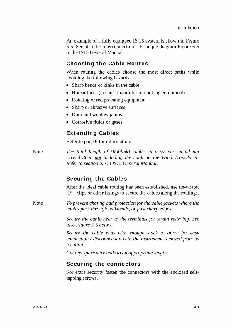
Figure 5-6 Securing connectors to the instrument
Make sure that all empty sockets have the protective bung inserted. Coat the connectors with silicone grease or petroleum jelly. These products will not harm the instrument.
5.5 Instrument head connections
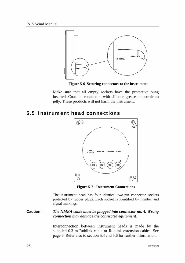
Figure 5-7 - Instrument Connections
The instrument head has four identical two-pin connector sockets protected by rubber plugs. Each socket is identified by number and signal markings.
Caution ! The NMEA cable must be plugged into connector no. 4. Wrong connection may damage the connected equipment.
Interconnection between instrument heads is made by the supplied 0.3 m Roblink cable or Roblink extension cables. See page 6. Refer also to section 5.4 and 5.6 for further information.
Installation
20220752J 27
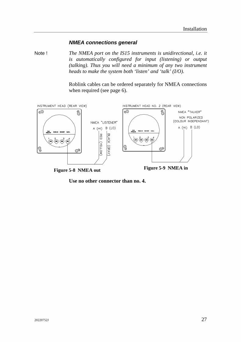
NMEA connections general
Note ! The NMEA port on the IS15 instruments is unidirectional, i.e. it is automatically configured for input (listening) or output (talking). Thus you will need a minimum of any two instrument heads to make the system both ‘listen’ and ‘talk’ (I/O).
Roblink cables can be ordered separately for NMEA connections when required (see page 6).
Figure 5-8 NMEA out Figure 5-9 NMEA in
Use no other connector than no. 4.
IS15 Wind Manual
28 20220752J
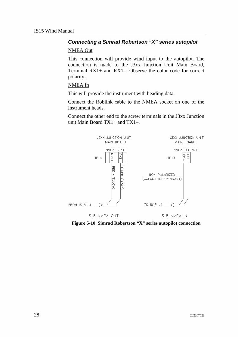
Connecting a Simrad Robertson “X” series autopilot NMEA Out This connection will provide wind input to the autopilot. The connection is made to the J3xx Junction Unit Main Board, Terminal RX1+ and RX1–. Observe the color code for correct polarity. NMEA In This will provide the instrument with heading data. Connect the Roblink cable to the NMEA socket on one of the instrument heads. Connect the other end to the screw terminals in the J3xx Junction unit Main Board TX1+ and TX1–.
Figure 5-10 Simrad Robertson “X” series autopilot connection
Installation
20220752J 29
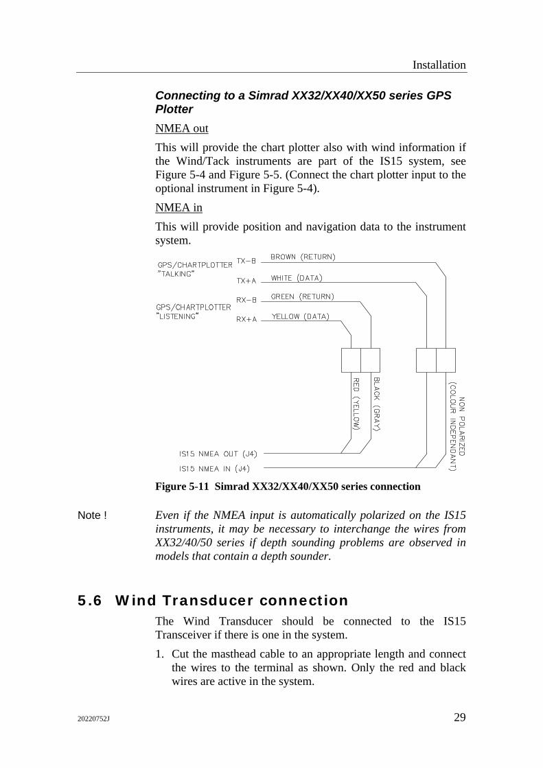
Connecting to a Simrad XX32/XX40/XX50 series GPS Plotter NMEA out This will provide the chart plotter also with wind information if the Wind/Tack instruments are part of the IS15 system, see Figure 5-4 and Figure 5-5. (Connect the chart plotter input to the optional instrument in Figure 5-4). NMEA in This will provide position and navigation data to the instrument system.
Figure 5-11 Simrad XX32/XX40/XX50 series connection
Note ! Even if the NMEA input is automatically polarized on the IS15 instruments, it may be necessary to interchange the wires from XX32/40/50 series if depth sounding problems are observed in models that contain a depth sounder.
5.6 Wind Transducer connection The Wind Transducer should be connected to the IS15 Transceiver if there is one in the system. 1. Cut the masthead cable to an appropriate length and connect
the wires to the terminal as shown. Only the red and black wires are active in the system.
IS15 Wind Manual
30 20220752J
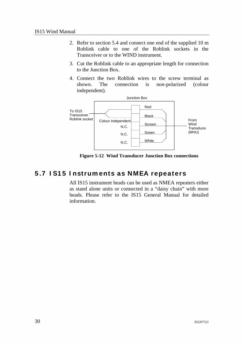
2. Refer to section 5.4 and connect one end of the supplied 10 m Roblink cable to one of the Roblink sockets in the Transceiver or to the WIND instrument.
3. Cut the Roblink cable to an appropriate length for connection to the Junction Box.
4. Connect the two Roblink wires to the screw terminal as shown. The connection is non-polarized (colour independent).
Red
Black
Screen
Green
White
Colour independent
To IS15TransceiverRoblink socket
Junction Box
FromWindTransducer(MHU)
N.C.
N.C.
N.C.
Figure 5-12 Wind Transducer Junction Box connections
5.7 IS15 Instruments as NMEA repeaters All IS15 instrument heads can be used as NMEA repeaters either as stand alone units or connected in a “daisy chain” with more heads. Please refer to the IS15 General Manual for detailed information.
Setting-Up
20220752J 31
6 SETTING-UP
6.1 First Time Turn on
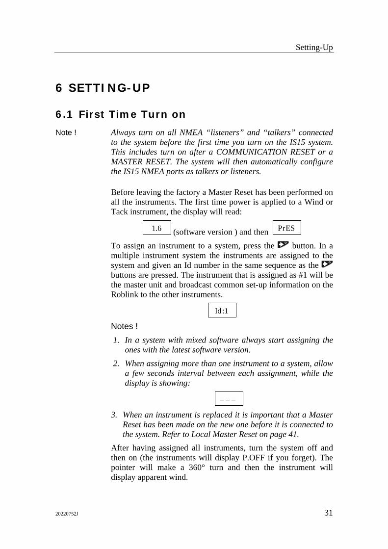
Note ! Always turn on all NMEA “listeners” and “talkers” connected to the system before the first time you turn on the IS15 system. This includes turn on after a COMMUNICATION RESET or a MASTER RESET. The system will then automatically configure the IS15 NMEA ports as talkers or listeners.
Before leaving the factory a Master Reset has been performed on all the instruments. The first time power is applied to a Wind or Tack instrument, the display will read:
1.6 (software version ) and then PrES To assign an instrument to a system, press the button. In a multiple instrument system the instruments are assigned to the system and given an Id number in the same sequence as the buttons are pressed. The instrument that is assigned as #1 will be the master unit and broadcast common set-up information on the Roblink to the other instruments.
Id :1 Notes ! 1. In a system with mixed software always start assigning the
ones with the latest software version. 2. When assigning more than one instrument to a system, allow
a few seconds interval between each assignment, while the display is showing:
– – – 3. When an instrument is replaced it is important that a Master
Reset has been made on the new one before it is connected to the system. Refer to Local Master Reset on page 41.
After having assigned all instruments, turn the system off and then on (the instruments will display P.OFF if you forget). The pointer will make a 360° turn and then the instrument will display apparent wind.
IS15 Wind Manual
32 20220752J
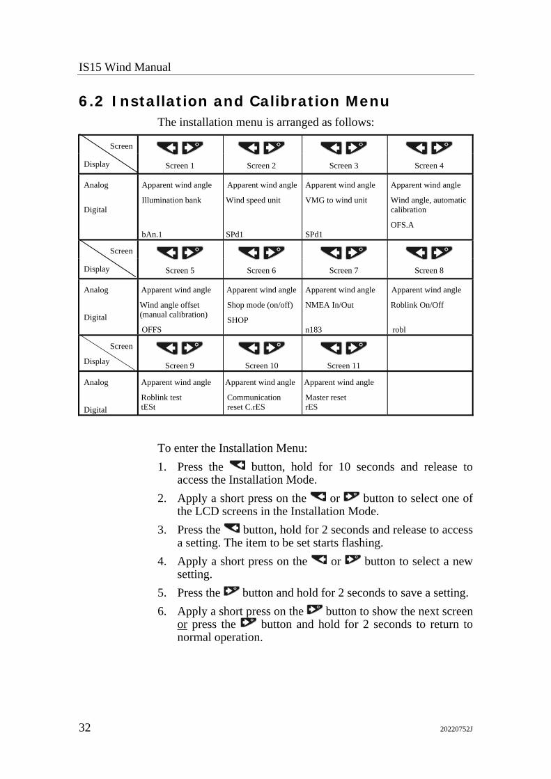
6.2 Installation and Calibration Menu The installation menu is arranged as follows:
Screen
Display
Screen 1
Screen 2
Screen 3
Screen 4
Analog Digital
Apparent wind angle
Illumination bank
bAn.1
Apparent wind angle
Wind speed unit
SPd1
Apparent wind angle
VMG to wind unit
SPd1
Apparent wind angle
Wind angle, automatic calibration
OFS.A
Screen
Display
Screen 5
Screen 6
Screen 7
Screen 8
Analog
Digital
Apparent wind angle
Wind angle offset (manual calibration)
OFFS
Apparent wind angle
Shop mode (on/off)
SHOP
Apparent wind angle
NMEA In/Out
n183
Apparent wind angle
Roblink On/Off
robl
Screen
Display
Screen 9
Screen 10
Screen 11
Analog
Digital
Apparent wind angle
Roblink test tESt
Apparent wind angle
Communication reset C.rES
Apparent wind angle
Master reset rES
To enter the Installation Menu: 1. Press the button, hold for 10 seconds and release to
access the Installation Mode. 2. Apply a short press on the or button to select one of
the LCD screens in the Installation Mode. 3. Press the button, hold for 2 seconds and release to access
a setting. The item to be set starts flashing. 4. Apply a short press on the or button to select a new
setting. 5. Press the button and hold for 2 seconds to save a setting. 6. Apply a short press on the button to show the next screen
or press the button and hold for 2 seconds to return to normal operation.

Setting-Up
20220752J 33
Screen 1 ILLUM. BANK [bAn.1] The display reads bAn.0 – bAn.2 The IS15 instrument system can have two separate banks of instruments. Setting the lighting level on one display will set all the other displays in that bank to the same level, but will not effect any displays in the other bank. For instance, the lighting level can be independently controlled for:
• The cockpit and chart table displays of a yacht.
• The cockpit and mast displays of a yacht.
• The cabin and flybridge of a power boat.
Note ! You can also have individual lighting on all instruments. Then the illumination bank setting must be 0.
To select the illumination bank that the particular instrument shall be allocated to, use the above procedure.
Screen 2 WIND SPEED UNIT SELECTION [SPd1] The display reads SPd1 – SPd4 with both arrows lit on top. Displayed wind speed units may be set to Knots, Metres Per Second, Beaufort or Kmh (shown in the LCD display as SPd1, SPd2, SPd3 or SPd4). To select the Wind Speed Unit, use the above procedure. The different speed units are selected according to the table below.
'SPd1' = Knots 'SPd2' = Metres Per Second 'SPd3' = Kmh 'SPd4' = Beaufort
Screen 3 VMG TO WIND UNIT SELECTION [SPd1]
Note ! This is the same unit as boat speed unit.
The display reads SPd1 – SPd3 with the centre arrows lit on top.
IS15 Wind Manual
34 20220752J
Displayed Velocity Made Good units may be set to Knots, Miles Per Hour or Kilometres Per Hour. (This will be the same as the systems setting for boat speed.) To select the VMG to Wind Unit use the above procedure. The different VMG to Wind units are selected according to the table below.
'SPd1' = Knots 'SPd2' = Kilometres Per Hour 'SPd3' = Miles Per Hour
Screen 4 WIND ANGLE OFFSET – AUTO CALIBRATION [OFS.A] The display reads OFS.A. The IS15 instrument system can be automatically corrected for errors in the mounting of the wind angle sensor. Head the vessel directly into the wind, and then activate the automatic calibration function. Any error in the wind angle will be corrected to zero the reading on the scale. To activate the Wind Angle Offset Auto Calibration press the
button for 2 seconds and the display will flash (two times) ‘Auto’ and then ‘done’. The display reads OFS.A, starts flashing and finally reads done.
Screen 5 WIND ANGLE OFFSET – MANUAL CALIBRATION [OFFS] Any residual errors in the apparent wind angle display can be corrected manually by entering the required offset. To select the Wind Angle Offset Manual Calibration use the above procedure. The display reads OFFS, then starts flashing 000.
• Adjust the wind angle to starboard using the button (positive reading).
• Adjust the wind angle to port using the button (negative reading).

Setting-Up
20220752J 35
Screen 6 SHOP MODE [SHOP] The instrument has a demonstration mode that can be activated by selecting ‘Shop’ On. This function is very useful for dealers when they want to demonstrate the IS15 system or when it is put on display on a show. The Shop Mode is turned off when power is turned off. Use the above procedure to select and activate the Shop mode. The display will show SHOP and then start flashing ‘OFF’ or ‘ON’. Select the preferred mode.
Note ! When in Shop Mode the instruments will display real data if any data is received.
Screen 7 NMEA IN/OUT [n 183] This screen allows you to manually change the NMEA ‘talker’ port = NMEA OUT to a ‘listener’ port = NMEA IN. Hence you need not make a Master reset or a Communication reset. Refer to chapter 6.1 First time turn on. See also note below. The setting is local to each instrument. Press the or button to select NMEA OUT. Press and hold the button to confirm.
Note ! If there is an active ‘talker’ connected to the NMEA port, you will not be able to change this port from ‘IN’ to an ‘OUT’ port unless the ‘talker’ is disconnected.
Screen 8 ROBLINK ON/OFF [robl] It is possible to turn off the Roblink. The display reads ‘robl’. Press the button and hold for 2 seconds. The LCD display shows (flashes) ‘Id:x’, ‘x’ being the instrument’s present Roblink Id. number. Press the or button to select Roblink OFF. Press and hold the button to confirm.
IS15 Wind Manual
36 20220752J
Notes ! 1. The Roblink must be turned Off when the instrument is used
as a single NMEA repeater. However, if more heads are daisy-chained as NMEA repeaters the Roblink must be On.
2. When the Roblink has been turned Off it will not default to ON even after a Master Reset. If required it must therefore be turned On again using the procedure above.
Screen 9 ROBLINK TEST [tESt] Refer to section 7 ‘Fault Finding’ for details.
Screen 10 COMMUNICATION RESET [C.rES] Allows you to reset the system communication (Roblink) in the event anomalies are observed on one or more instruments. This reset will not default the calibration or settings. Press the button and hold for 2 seconds. The LCD display shows ‘P.OFF’. Turn the system off, refer to the beginning of this section and assign the instrument(s) to the system.
Screen 11 MASTER RESET [rES] When a MASTER RESET is performed on one of the instruments in a system it becomes system wide and all instruments are reset to default values.
Note ! Do not perform a Master Reset unintentionally because it will default settings and calibration values.
Press the button and hold for 2 seconds. The LCD display shows ‘P.OFF’. Turn the system off, refer to the beginning of this section and assign the instrument(s) to the system.
Note ! After the Master Reset a new set-up has to be performed.
Fault Finding
20220752J 37
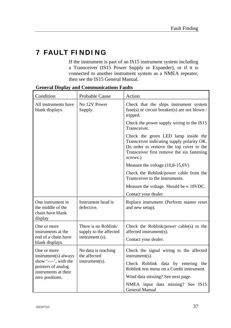
7 FAULT FINDING If the instrument is part of an IS15 instrument system including a Transceiver (IS15 Power Supply or Expander), or if it is connected to another instrument system as a NMEA repeater, then see the IS15 General Manual.
General Display and Communications Faults
Condition Probable Cause Action All instruments have blank displays.
No 12V Power Supply.
Check that the ships instrument system fuse(s) or circuit breaker(s) are not blown / tripped.
Check the power supply wiring to the IS15 Transceiver.
Check the green LED lamp inside the Transceiver indicating supply polarity OK. (In order to remove the top cover to the Transceiver first remove the six fastening screws.)
Measure the voltage (10,8-15,6V)
Check the Roblink/power cable from the Transceiver to the instruments.
Measure the voltage. Should be ≈ 18VDC.
Contact your dealer.
One instrument in the middle of the chain have blank display
Instrument head is defective.
Replace instrument (Perform master reset and new setup).
One or more instruments at the end of a chain have blank displays.
There is no Roblink/ supply to the affected instrument (s).
Check the Roblink/power cable(s) to the affected instrument(s).
Contact your dealer.
One or more instrument(s) always show ‘----’, with the pointers of analog instruments at their zero positions.
No data is reaching the affected instrument(s).
Check the signal wiring to the affected instrument(s).
Check Roblink data by entering the Roblink test menu on a Combi instrument.
Wind data missing? See next page.
NMEA input data missing? See IS15 General Manual
IS15 Wind Manual
38 20220752J
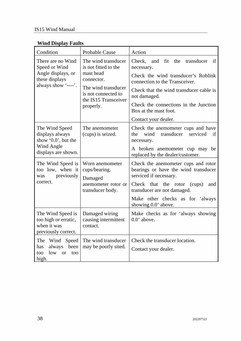
Wind Display Faults
Condition Probable Cause Action
There are no Wind Speed or Wind Angle displays, or these displays always show ‘----’.
The wind transducer is not fitted to the mast head connector. The wind transducer is not connected to the IS15 Transceiver properly.
Check, and fit the transducer if necessary. Check the wind transducer’s Roblink connection to the Transceiver. Check that the wind transducer cable is not damaged. Check the connections in the Junction Box at the mast foot. Contact your dealer.
The Wind Speed displays always show ‘0.0’, but the Wind Angle displays are shown.
The anemometer (cups) is seized.
Check the anemometer cups and have the wind transducer serviced if necessary. A broken anemometer cup may be replaced by the dealer/customer.
The Wind Speed is too low, when it was previously correct.
Worn anemometer cups/bearing. Damaged anemometer rotor or transducer body.
Check the anemometer cups and rotor bearings or have the wind transducer serviced if necessary. Check that the rotor (cups) and transducer are not damaged. Make other checks as for ‘always showing 0.0’ above.
The Wind Speed is too high or erratic, when it was previously correct.
Damaged wiring causing intermittent contact.
Make checks as for ‘always showing 0.0’ above.
The Wind Speed has always been too low or too high.
The wind transducer may be poorly sited.
Check the transducer location. Contact your dealer.
Fault Finding
20220752J 39
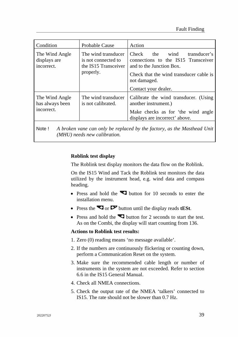
Condition Probable Cause Action
The Wind Angle displays are incorrect.
The wind transducer is not connected to the IS15 Transceiver properly.
Check the wind transducer’s connections to the IS15 Transceiver and to the Junction Box. Check that the wind transducer cable is not damaged. Contact your dealer.
The Wind Angle has always been incorrect.
The wind transducer is not calibrated.
Calibrate the wind transducer. (Using another instrument.) Make checks as for ‘the wind angle displays are incorrect’ above.
Note ! A broken vane can only be replaced by the factory, as the Masthead Unit (MHU) needs new calibration.
Roblink test display The Roblink test display monitors the data flow on the Roblink. On the IS15 Wind and Tack the Roblink test monitors the data utilized by the instrument head, e.g. wind data and compass heading.
• Press and hold the button for 10 seconds to enter the installation menu.
• Press the or button until the display reads tESt.
• Press and hold the button for 2 seconds to start the test. As on the Combi, the display will start counting from 136.
Actions to Roblink test results: 1. Zero (0) reading means ‘no message available’. 2. If the numbers are continuously flickering or counting down,
perform a Communication Reset on the system. 3. Make sure the recommended cable length or number of
instruments in the system are not exceeded. Refer to section 6.6 in the IS15 General Manual.
4. Check all NMEA connections. 5. Check the output rate of the NMEA ‘talkers’ connected to
IS15. The rate should not be slower than 0.7 Hz.

IS15 Wind Manual
40 20220752J
8 MAINTENANCE
8.1 General Maintenance
Caution ! Do not use any abrasives, chemical cleaners, petrol or diesel to clean this unit.
The instrument head will require no maintenance apart from occasional cleaning. Use fresh water and a mild soap solution (not a detergent).
8.2 Annual Maintenance Check all connections to the instrument and, if necessary, cover with silicone grease or petroleum jelly. The wind transducer is a robust unit that should give you years of reliable service. However, it will benefit from an application of silicone grease to the connector at the beginning of each season. It is also recommended that the wand is removed over Winter if the boat is not in use. To prevent corrosion of the connector, always fit the protective cap to the socket when the wand has been removed.
Note ! A broken vane can only be replaced by the factory, as the wind transducer needs new calibration.
A broken anemometer cup may be replaced by the dealer/owner.
8.3 Removal of Instrument 1. If rear access is possible unplug the Roblink connectors from
the rear of the instrument. 2. Remove the four front panel corners and the fixing screws. 3. Pull the instrument free from the panel, being careful not to
strain the wiring if the connectors have not yet been removed. 4. If they are not yet removed, unplug the Roblink connectors
from the rear of the case, and make up the cables if necessary.
Maintenance
20220752J 41
8.4 Return for Service Prior to return please ensure that an instrument that is believed to be faulty is correctly installed, the wiring is in good condition and correct, that all connections are secure, and that a correct supply is present at it’s Roblink/power connector. Should the unit have to be returned to your dealer, adequate packing must be used. Please ensure that your name, telephone number, return address, a clear fault description, and if possible a copy of the receipt of purchase are included with any returned equipment. Simrad and their representatives are not responsible for any equipment lost in transit. Please quote the instrument’s serial number in all correspondence. This is found on the back of the instrument.
8.5 Local Master Reset When an instrument is leaving the factory a Master Reset has been made. However, if an instrument is being used in a different system or setup, you can perform a local Master Reset on the instrument in that system before it is disconnected and move it to a system where you want to put it. Refer to screen 7 on page 35. 1. Turn off the Roblink as per instructions 2. Perform a Master Reset as per instructions 3. Turn on the Roblink as per instructions
You can now install the instrument in another system without having to make a system wide Master Reset and loose the existing calibration and settings in that system.
IS15 Wind Manual
42 20220752J
9 SPARE PARTS LIST 22092100 IS15 Wind Instrument 22092704 IS15 Wind PROM (programmed) V..R.. 20220794 IS15 Wind/Tack Operator’s Quick Reference Guide 22092142 IS15 Tack Instrument 22092712 IS15 Tack PROM (programmed) V..R.. 20220794 IS15 Wind/Tack Operator’s Quick Reference Guide 22092837 IS15 Mounting kit consisting of:
22084529 Cabinet corners 44165181 Screw 3.5x32 44160232 Screw (for securing the connectors)
22091854 IS15 Protection cover 22092241 IS15 Panel gasket 22092753 IS15 Wind Transducer 22093017 IS15 Wind Transducer PROM (programmed) V..R.. 22092415 IS15 Wind Transducer PCB 44166858 IS15 Wind Transducer Bracket w/30m (100’) cable 44175446 Junction box Roblink Cables 22092019 Roblink Cable 0,3 m 22093728 Roblink Cable 2 m (6,5’) 22092548 Roblink Cable 5 m (16,5’) 22092027 Roblink Cable 10 m (33’) 22093587 Roblink Power Cable 22092001 Cable Adapter (for interconnection)